

Page 1

PROFIBUS Optical Bus Terminal
(OBT)
___________________
___________________
___________________
___________________
___________________
___________________
___________________
___________________
SIMATIC NET
PG/PC - PROFIBUS
PROFIBUS Optical Bus Terminal
(OBT)
Operating Instructions
04/2016
C79000
Introduction
1
Components of the product
2
Functional description
3
Network topology
4
Commissioning
5
Help with problems during
operation
6
Technical data
7
Approvals and certificates
8
-G8976-C122-07
Page 2

Siemens AG
Division Process Industries and Drives
Postfach 48 48
90026 NÜRNBERG
GERMANY
Document order number: C79000-G8976-C122
Ⓟ
Copyright © Siemens AG 2009 - 2016.
All rights reserved
Legal information
Warning notice system
DANGER
indicates that death or severe personal injury will result if proper precautions are not taken.
WARNING
indicates that death or severe personal injury may result if proper precautions are not taken.
CAUTION
indicates that minor personal injury can result if proper precautions are not taken.
NOTICE
indicates that property damage can result if proper precautions are not taken.
Qualified Personnel
personnel qualified
Proper use of Siemens products
WARNING
Siemens products may only be used for the applications described in the catalog and in the relevant technical
re required to ensure that the products operate safely and without any problems. The permissible
ambient conditions must be complied with. The information in the relevant documentation must be observed.
Trademarks
Disclaimer of Liability
This manual contains notices you have to observe in order to ensure your personal safety, as well as to prevent
damage to property. The notices referring to your personal safety are highlighted in the manual by a safety alert
symbol, notices referring only to property damage have no safety alert symbol. These notices shown below are
graded according to the degree of danger.
If more than one degree of danger is present, the warning notice representing the highest degree of danger will
be used. A notice warning of injury to persons with a safety alert symbol may also include a warning relating to
property damage.
The product/system described in this documentation may be operated only by
task in accordance with the relevant documentation, in particular its warning notices and safety instructions.
Qualified personnel are those who, based on their training and experience, are capable of identifying risks and
avoiding potential hazards when working with these products/systems.
Note the following:
documentation. If products and components from other manufacturers are used, these must be recommended
or approved by Siemens. Proper transport, storage, installation, assembly, commissioning, operation and
maintenance a
All names identified by ® are registered trademarks of Siemens AG. The remaining trademarks in this publication
may be trademarks whose use by third parties for their own purposes could violate the rights of the owner.
We have reviewed the contents of this publication to ensure consistency with the hardware and software
described. Since variance cannot be precluded entirely, we cannot guarantee full consistency. However, the
information in this publication is reviewed regularly and any necessary corrections are included in subsequent
editions.
for the specific
04/2016 Subject to change
Page 3

Table of contents
1 Introduction ............................................................................................................................................. 5
2 Components of the product ..................................................................................................................... 7
3 Functional description ............................................................................................................................. 9
4 Network topology .................................................................................................................................. 13
5 Commissioning ..................................................................................................................................... 17
6 Help with problems during operation ..................................................................................................... 27
7 Technical data ...................................................................................................................................... 29
8 Approvals and certificates ..................................................................................................................... 33
3.1 Interfaces .................................................................................................................................. 9
3.2 Opto-electrical signal conversion and signal regeneration ....................................................... 9
3.3 Supported FO fiber types ........................................................................................................ 10
3.4 Displays .................................................................................................................................. 10
3.5 Operator controls .................................................................................................................... 12
4.1 Optical bus .............................................................................................................................. 13
4.2 Integration of long FO cable runs ........................................................................................... 14
4.3 Integrating RS-485 segments ................................................................................................. 15
5.1 Procedure for commissioning ................................................................................................. 20
5.2 Installation ............................................................................................................................... 20
6.1 Help with problems during operation ...................................................................................... 27
8.1 Notes on the CE mark............................................................................................................. 33
PROFIBUS Optical Bus Terminal (OBT)
Operating Instructions, 04/2016, C79000-G8976-C122-07
3
Page 4

Table of contents
PROFIBUS Optical Bus Terminal (OBT)
4 Operating Instructions, 04/2016, C79000-G8976-C122-07
Page 5
1
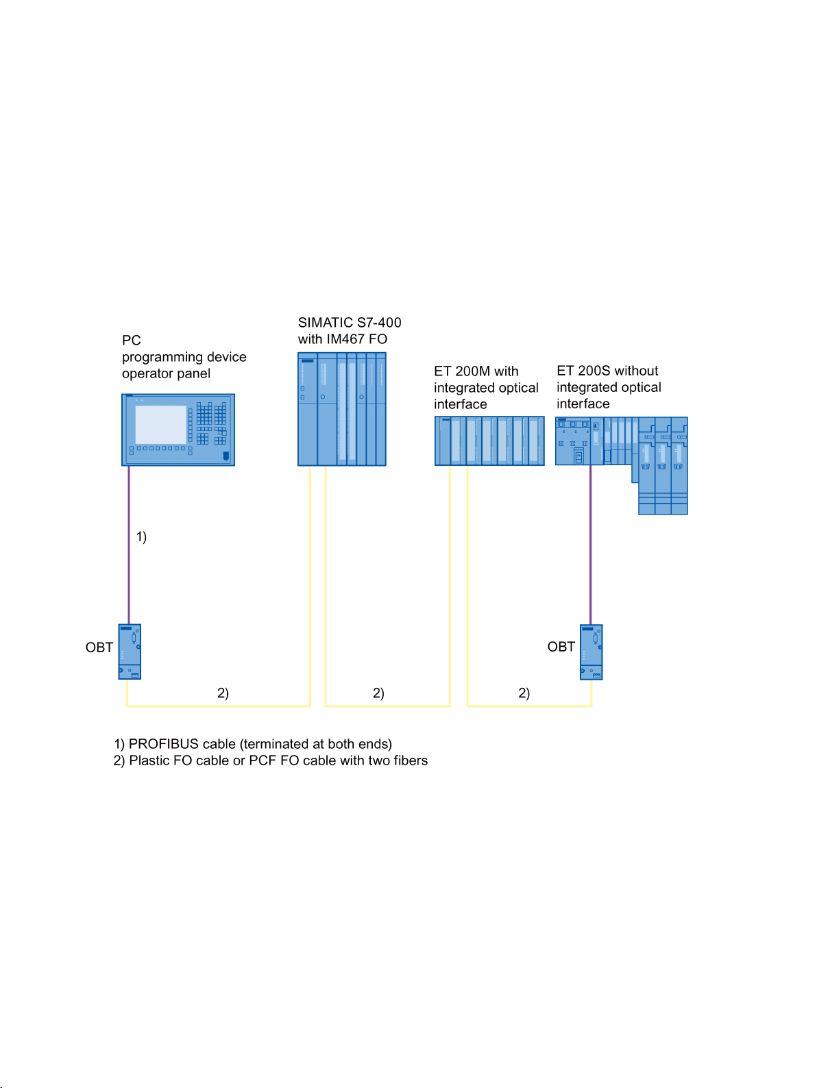
The PROFIBUS OBT (Optical Bus Terminal) it is a network component used in optical
PROFIBUS DP fieldbus networks. It allows the connection of either a single device without
an integrated optical interface or an RS-485 segment to the optical PROFIBUS DP. The
following figure shows an example of a configuration.
Image 1-1 Example of an optical PROFIBUS DP configuration
PROFIBUS Optical Bus Terminal (OBT)
Operating Instructions, 04/2016, C79000-G8976-C122-07
5
Page 6

Introduction
Connections
Sensitivity
Power supply
Operating state
Mechanical construction
The connection between the individual bus nodes takes the form of an optical bus with twofiber plastic fiber-optic cables (plastic fiber-optic cables are also known as POF, Polymer
Optical Fiber) or PCF fiber-optic cables (PCF = Polymer Cladded Fiber, synonymous with
HCS1 fiber-optic cable). Since fiber-optic cables (FO cable) are completely insensitive to
EMC interference, complex grounding concepts and protection measures are unnecessary.
This also applies to the laying of a equipotential bonding cables. Due to be opto-electronic
conversion, there is automatically electrical isolation so that potential differences as can
occur in extensive plants are no longer noticed.
1) HCS is a registered trademark of Spectran Speciality Optics and stands for "Hard Polymer
Cladded Silica Fiber".
Just as the FO cable is insensitive to EMC interference, an FO cable also emits no
electromagnetic waves into its environment. Sensitive electronic devices located in the
vicinity of the fiber-optic cable therefore need no additional protection or suppression
measures.
The OBT requires an operating power supply of 24 VDC that is connected via two screw
terminals.
LEDs signal the current operating state and any problems affecting operation.
The mechanical construction consists of a compact plastic housing that can be mounted
either on a DIN rail or any flat surface.
PROFIBUS Optical Bus Terminal (OBT)
6 Operating Instructions, 04/2016, C79000-G8976-C122-07
Page 7

2
Supplied
Not supplied
● 1 x PROFIBUS OBT
● 1 x Operating instructions (Compact) A5E03345735-01
● Plastic fiber-optic cables, sold in meters
● Assembly tool for fiber-optic cable connectors
● Operating Instructions for the PROFIBUS OBT
● Fiber-optic cable connectors
PROFIBUS Optical Bus Terminal (OBT)
Operating Instructions, 04/2016, C79000-G8976-C122-07
7
Page 8

Components of the product
PROFIBUS Optical Bus Terminal (OBT)
8 Operating Instructions, 04/2016, C79000-G8976-C122-07
Page 9

3
3.1
Interfaces
3.2
Opto-electrical signal conversion and signal regeneration
The OBT is a repeater with 3 channels.
The OBT has the following interfaces for connection of PROFIBUS DP segments:
● Channel 1 (CH1) is an electrical RS-485 interface. It is designed as a 9-pin D-sub female
connector. A PROFIBUS DP node or a PC, PG, OP or an RS-485 segment can be
connected to the OBT via this channel. The copper segment should be kept as short as
possible since this can couple in disturbances into the optical PROFIBUS DP.
● Channel 2 (CH2) and channel 3 (CH3) are optical interfaces. These are designed as
duplex female connectors. The end a two-fiber plastic or PCF fiber-optic cable fitted with
two simplex male connectors is connected to each of these duplex female connectors.
The OBT also has a 3-pin terminal for connection of the 24 V power supply and, if
necessary, a ground cable.
The OBT converts the RS-485 level received at channel 1 into an optical signal level that is
output via channels 2 and channel 3.
Signals received at channel 2 or 3 are converted to electrical signals and
● output on channel 1 as an electrical signal
● they are then converted into an optical signal again and output on the other optical
channel.
There is no echo on the receive channel; in other words, received signals are not sent back
on the same channel.
The OBT regenerates the signals in amplitude and time. This makes it possible to cascade
up to 126 modules in an optical bus. The cascading depth is simply limited by the monitoring
times of the connected devices.
The latency per OBT is 6 bit times.
PROFIBUS Optical Bus Terminal (OBT)
Operating Instructions, 04/2016, C79000-G8976-C122-07
9
Page 10

Functional description
3.3
Supported FO fiber types
Fiber type
Link length between 2 devices
and max. max. 200 dB/km cable attenuation
3.4
Displays
L+ 24 V (green)
not lit:
Power supply missing or internal power supply is defective or short
circuited
flashes:
Power supply present, transmission speed not yet set
lit green:
Transmission speed set, power supply functioning correctly
3.3 Supported FO fiber types
The OBT supports the fiber types listed in the following table:
Table 3- 1 Achievable FO cable distance between the two devices on optical PROFIBUS DP
Plastic FO cable 980/1000 μm with 2 fibers
PCF FO cable 200/230 μm with 2 fibers and
max. max. 10 dB/km cable attenuation
The specified link length between the devices assumes that the partner devices use the
same optical components as the OBT. This is, for example, the case with the IM 153–2 FO
and IM 467 FO.
The transmission speed is not dependent on the fiber type used or the cable length. This can
be up to 12 Mbps.
The following accessories are available:
● Plastic fiber-optic cable (sold in meters), connectors/polishing set and the assembly tool
for plastic fiber-optic cable
The plastic fiber-optic cables do not have connectors fitted. The plastic simplex
connectors can be fitted easily on site with the available tools.
● PCF FO cable (preassembled)
PCF cables with 4 PCF simplex connectors fitted are available in fixed lengths.
0.1 to 50 meters
0 to 300 meters
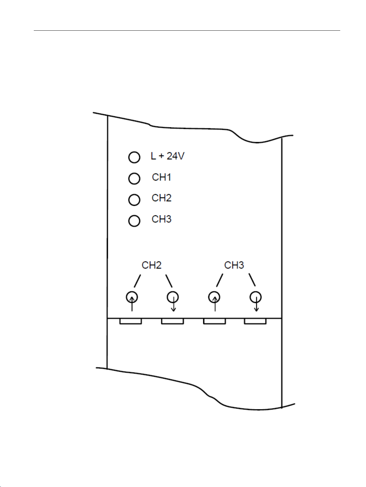
The OBT has 4 LEDs to display the operating state.
PROFIBUS Optical Bus Terminal (OBT)
10 Operating Instructions, 04/2016, C79000-G8976-C122-07
-
Page 11
Functional description
CH1, CH2 , CH3 (channel 1 to 3, yellow)
not lit:
Data is not being received
lit yellow:
Data is being received
3.4 Displays
PROFIBUS Optical Bus Terminal (OBT)
Operating Instructions, 04/2016, C79000-G8976-C122-07
Image 3-1 LEDs on the front panel
11
Page 12

Functional description
3.5
Operator controls
3.5 Operator controls
The OBT itself does not have any controls. The only point to remember is that the
PROFIBUS connecting cable connected to channel 1 (does not ship with product) needs to
be terminated at both ends.
PROFIBUS Optical Bus Terminal (OBT)
12 Operating Instructions, 04/2016, C79000-G8976-C122-07
Page 13

4
4.1
Optical bus
Note
If problems are detected on the electrical interface, there is a segmentation, in other words,
the frames are not forwarded. The segmentation is canceled when the problem has been
eliminated. In this case, it is assumed that a minimum number of error
received on the electrical channel. The segmentation is also canceled when no frames are
received for at least 1 second. In this case, it is assumed that unplugging the PROFIBUS
connector caused problems and that there are no more nodes on the
Along with other SIMATIC devices such as the IM 153–2 FO or IM 467 FO, OBTs are
connected to optical PROFIBUS DP to form an optical bus.
PROFIBUS DP bus nodes with an RS-485 interface are connected to channel 1 of the OBT
via bus connectors and a PROFIBUS bus cable. The bus segment must be terminated at
both ends.
The OBT can be used at any point on the optical bus. If it is used at the start or end, the
unused optical channel must remain closed with the rubber plug. This prevents
contamination of the optical elements and disturbances caused by incident light.
The connection on an optical bus is made using two-fiber plastic FO cable (max length 50 m)
or PCF FO cable (max. length 300 m). The FO cables have two simplex connectors fitted at
both ends.
The FO connection between two devices is established by the optical transmitter of one
device being connected to the optical receiver of the other device via a fiber, while the optical
receiver of the first device is connected to the optical transmitter of the other (crossover
cable).
If an OBT or a fiber-optic cable fails, the network is split into two separate networks.
Depending on the location of the problem, devices are no longer accessible.
-free frames were
electrical channel.
The OBT does not support the establishment of single-fiber rings or redundant ring
structures.
PROFIBUS Optical Bus Terminal (OBT)
Operating Instructions, 04/2016, C79000-G8976-C122-07
13
Page 14
Network topology
4.2
Integration of long FO cable runs
4.2 Integration of long FO cable runs
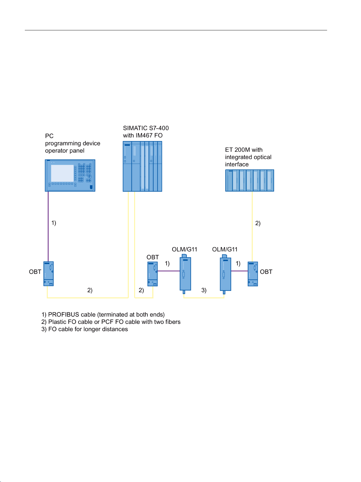
The maximum permitted length of PCF FO cable with the OBT is 300 m. If longer FO links or
other FO cable types, for example glass graded index fibers or monomode fibers are
necessary, they can be used by combining OBTs with OLMs (Optical Link Module). In this
situation, the OBT is connected electrically with the OLM (OBT/CH 1 to OLM/CH 1) and the
OLM is connected to the long FO cable link. At the end of the FO cable link, the combination
is reversed with a second OLM/OBT pair.
Image 4-1 Example of covering longer FO links with OBTs and OLMs
The maximum permitted transmission speed and the type and maximum length of the FO
cable link is decided by the OLM type.
PROFIBUS Optical Bus Terminal (OBT)
14 Operating Instructions, 04/2016, C79000-G8976-C122-07
Page 15
Network topology
4.3
Integrating RS-485 segments
4.3 Integrating RS-485 segments
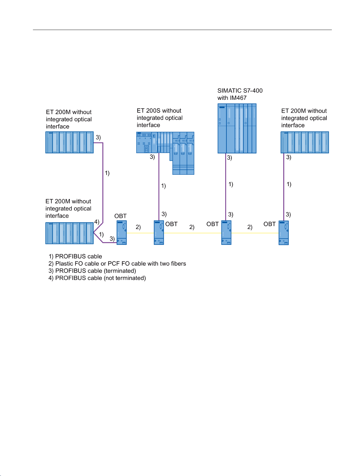
The OBT allows the attachment of a PROFIBUS RS-485 segment.
Image 4-2 Example of the integration of RS-485 segments
PROFIBUS Optical Bus Terminal (OBT)
Operating Instructions, 04/2016, C79000-G8976-C122-07
15
Page 16

Network topology
4.3 Integrating RS-485 segments
PROFIBUS Optical Bus Terminal (OBT)
16 Operating Instructions, 04/2016, C79000-G8976-C122-07
Page 17

5
Note
Use the PROFIBUS OBT only as intended in these Operating Instructions.
Note
Pay particular attention to all warnings and notices relevant to safety.
WARNING
Note
Never look directly into the opening of the optical transmission diode. The emitted light beam
could endanger your eyes.
Note
Never connect the PROFIBUS OBT to a 100 V
Note
Install the device so that the climatic limit values in the technical specifications are adhered
to.
Note
The RS
isolation relates to functionality and is not a safety measure.
Operate the PROFIBUS OBT only with safety extra-low voltage complying with IEC 950 /
EN 60 950/VDE 0805 of maximum +28.8 V (typically +24 V). The power source must meet
the requirements of the UL/CSA approval for NEC Class 2 according to the National
Electrical Code (r) (ANSI / NFPA 70).
- 240 V power supply.
-485 channel CH1 of the PROFIBUS OBT is isolated from the 24 V input. This
PROFIBUS Optical Bus Terminal (OBT)
Operating Instructions, 04/2016, C79000-G8976-C122-07
17
Page 18

Commissioning
Note
Make sure that the PROFIBUS OBT is adequately grounded by connecting the DIN rail or
mounting plate to local ground with low resistance and inductance. When securing the
module to a mounting plate, run a cable from the grounding terminal of the OBT to the
nearest possible ground, keeping the cable as short as possible.
The shield of the PROFIBUS cable must be contacted. To do this, strip the insulation from
the end of the PROFIBUS cable and connect the shield to functional earth.
Note
Only use bus cables approved for PROFIBUS as the RS
Note
The OBT housing must not be opened.
General notices on use in hazardous areas
WARNING
Risk of explosion when connecting or disconnecting the device
WARNING
WARNING
-485 bus cable.
WARNING – EXPLOSION HAZARD
DO NOT CONNECT OR DISCONNECT EQUIPMENT WHEN A FLAMMABLE OR
COMBUSTIBLE ATMOSPHERE IS PRESENT.
WARNING – EXPLOSION HAZARD
DO NOT DISCONNECT WHILE CIRCUIT IS LIVE UNLESS AREA IS KNOWN TO BE
NON-HAZARDOUS.
WARNING – EXPLOSION HAZARD
SUBSTITUTION OF COMPONENTS MAY IMPAIR SUITABILITY FOR CLASS I, DIVISION
2.
PROFIBUS Optical Bus Terminal (OBT)
18 Operating Instructions, 04/2016, C79000-G8976-C122-07
Page 19

Commissioning
WARNING
WARNING
General notice on use in hazardous areas according to ATEX
WARNING
Requirements for the cabinet/enclosure
WARNING
Requirements for the cabinet/enclosure
WARNING
Protection against transient voltage surges
WARNING
Suitable cables for high temperatures
This equipment is suitable for use in Class I, Division 2, Groups A, B, C, and D or nonhazardous locations only.
This equipment is suitable for use in Class I, Zone 2, Group IIC or non-hazardous locations
only.
When used in hazardous environments corresponding to Class I, Division 2 or Class I,
Zone 2, the device must be installed in a cabinet or a suitable enclosure.
The modules must be installed in a suitable enclosure with at least degree of protection
IP54 according to EN 60529. The environmental conditions under which the equipment will
be used must be taken into account.
Take measures to prevent transient voltage surges of more than 40 % of the rated voltage.
This is the case if you only operate devices with SELV (safety extra-low voltage).
If the temperature exceeds 70 °C at the entry point of the cable or the cable channel under
conditions specified by the approval, or 80 °C where the conductors branch, the
temperature specification of the selected cable must correspond to the actual measured
temperature.
PROFIBUS Optical Bus Terminal (OBT)
Operating Instructions, 04/2016, C79000-G8976-C122-07
19
Page 20

Commissioning
5.1
Procedure for commissioning
5.2
Installation
Mounting the PROFIBUS OBT
Mounting on a DIN rail
5.1 Procedure for commissioning
Commissioning the PROFIBUS OBT involves the following steps:
● Mounting the PROFIBUS OBT;
● Connecting the power supply;
● Connecting the optical bus cables;
● Connecting the electrical RS-485 bus cable.
The PROFIBUS OBTs can be mounted either on a 35 mm DIN rail with a height of 15 mm
according to DIN 50 022 - 35 x 15 or directly on a flat surface.
1. Install the device so that the climatic limit values in the technical specifications are
adhered to.
2. Make sure that there is adequate space to connect the bus and power supply cables.
3. Mount the modules only on a rail or mounting plate that is grounded with low resistance
and inductance. When securing the module to a mounting plate, run a cable from the
grounding terminal of the OBT to the nearest possible ground, keeping the cable as short
as possible.
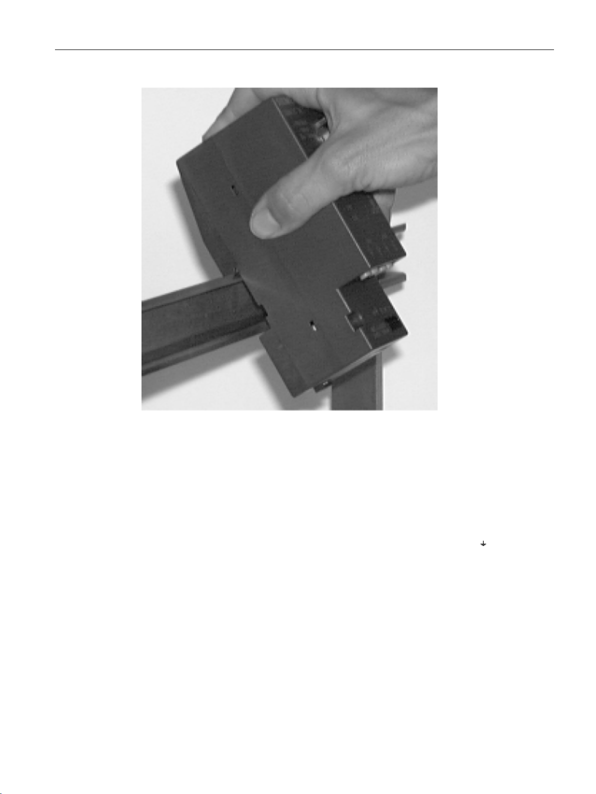
Fit the upper catch of the module over the DIN rail and push in the lower part of the module
as shown in Figure 5-1 until it clicks in place.
To remove the module, pull down the locking lever.
PROFIBUS Optical Bus Terminal (OBT)
20 Operating Instructions, 04/2016, C79000-G8976-C122-07
Page 21
Commissioning
Mounting on a mounting plate
5.2 Installation
Image 5-1 Mounting a module on a DIN rail
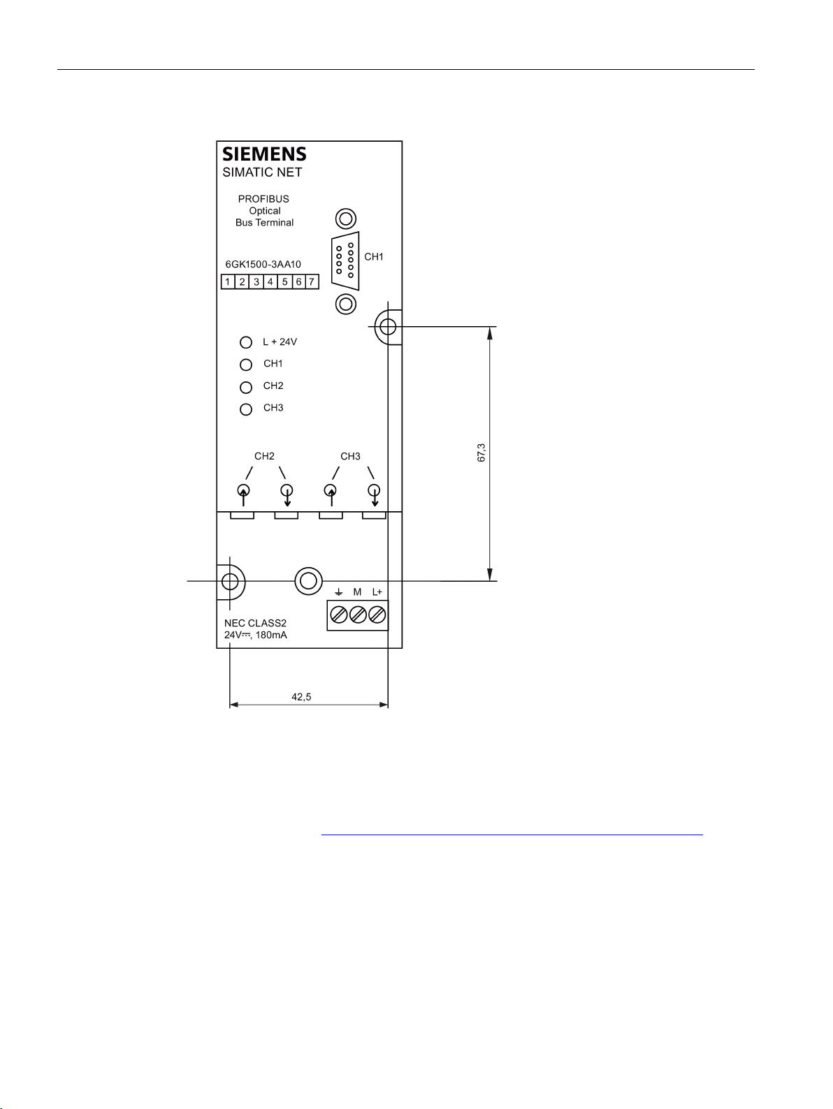
The PROFIBUS OBTs have two holes. These allow mounting on any flat surface, for
example on the mounting plate of a cabinet.
Drill two holes in the mounting plate as shown in the drilling template in Figure 5-2.
Secure the module with two machine screws (for example M3 x 75 and M3 x 55).
Make sure that there is a reliable electrical connection between the terminal
housing and the grounded mounting plate using a grounding cable of at least 2.5 mm
of the module
2
.
PROFIBUS Optical Bus Terminal (OBT)
Operating Instructions, 04/2016, C79000-G8976-C122-07
21
Page 22
Commissioning
Instructions for assembling plastic fiber-optic cable (with photos)
5.2 Installation
Image 5-2 Mounting a module on a mounting plate
You will find detailed instructions (with photos) on fitting connectors to plastic fiber-optic
cables on the Internet (https://support.industry.siemens.com/cs/de/en/view/35222591
PROFIBUS Optical Bus Terminal (OBT)
22 Operating Instructions, 04/2016, C79000-G8976-C122-07
)
Page 23
Commissioning
Connecting the operating power supply
5.2 Installation
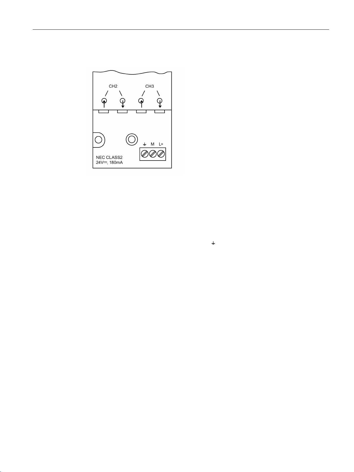
Image 5-3 Pin assignment of the 3-pin terminal block – grounding terminal ↓ and power supply M,
L+
1. Supply the PROFIBUS OBT only with a stabilized safety extra-low voltage complying with
IEC 950 / EN 60 950/VDE 0805 of nominally 24 V (minimum 19.2 V and maximum 28.8
V). The power source must meet the requirements of NEC Class 2 according to the
UL/CSA approval.
2. If the PROFIBUS OBT is not mounted on a grounded DIN rail, run a grounding cable with
2
a cross-section of 2.5 mm
from the terminal to the nearest ground keeping the cable
as short as possible.
PROFIBUS Optical Bus Terminal (OBT)
Operating Instructions, 04/2016, C79000-G8976-C122-07
23
Page 24
Commissioning
Connecting the optical bus cables
5.2 Installation
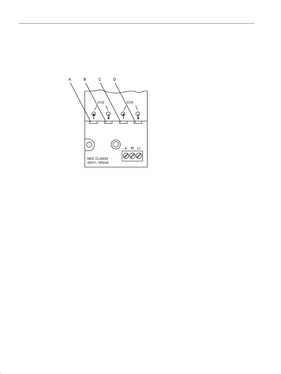
Image 5-4 View of the module from the side with the optical channels CH2 and CH3
A = CH2, optical receiver
B = CH2, optical transmitter
C = CH3, optical receiver
D = CH3, optical transmitter
Connect the individual PROFIBUS OBTs using a duplex fiber-optic cable fitted with two pairs
of simplex connectors.
Make sure that an optical input is connected to an optical output (crossover connection).
Provide adequate strain relief for the fiber-optic cable and remember the minimum bend radii
of the FO cable.
Close unused FO cable sockets with the supplied plastic plugs. Incident light from the
surroundings can cause disturbances on the PROFIBUS network particularly, if the
surroundings are very bright.
Remember the minimum and maximum length of the FO cable and the permitted fiber types
listed in Table 1 and in the technical specifications.
Make sure that no dust gets into the optical components. Dust in the optical components can
make them unusable.
PROFIBUS Optical Bus Terminal (OBT)
24 Operating Instructions, 04/2016, C79000-G8976-C122-07
Page 25

Commissioning
Note
If the fiber juts out beyond the surface of the connector, the connector must not be inserted
in the socket. Otherwise there is a risk of destroying the optical components.
Connecting the electrical RS-485 cable
5.2 Installation
The fiber of the FO cable must be flush with the surface of the connector.
Channel CH1 is used to connect a single PROFIBUS DP end device or an RS-485 segment.
CH1 is designed as an electrical RS-485 interface with a 9-pin D-sub female connector.
1. As the RS-485 bus cable, use only shielded and twisted SIMATIC NET two-wire cables
for PROFIBUS.
2. Do not connect any RS-485 bus cables that are laid entirely or partly outdoors.
Otherwise, lightning strikes in the surroundings could destroy the PROFIBUS OBTs. If
you have bus connections that leave the building, use fiber-optic cables whenever
possible.
3. Disconnect the RS-485 bus cable from the OBT if you have not connected a node to the
other end of the cable. Coupling in interference can cause disturbances on PROFIBUS.
PROFIBUS Optical Bus Terminal (OBT)
Operating Instructions, 04/2016, C79000-G8976-C122-07
25
Page 26

Commissioning
5.2 Installation
PROFIBUS Optical Bus Terminal (OBT)
26 Operating Instructions, 04/2016, C79000-G8976-C122-07
Page 27

6
6.1
Help with problems during operation
LED display
Possible cause of problems
Interruption of the receive FO cable with extraneous light
L+ 24 V LED not lit
L+ 24 V LED flashes
CH1 LED not lit
CH1 LED lit
PROFIBUS nodes are, however, signaling problems on the
bus
CH2, CH3 LED not lit
CH2, CH3 LED lit
PROFIBUS nodes are, however, signaling problems on the
bus
• Power supply failed
• OBT defective
• The transmission speed could not be set
• One or more wires of the RS-485 bus cable is interrupt-
ed
• Wires A and B of the RS-485 bus cable had been
swapped over
• Connected PROFIBUS node is defective or is not trans-
mitting
• PROFIBUS node or RS-485 segment is not connected
or connected or PROFIBUS node is not turned on
• Wires A and B of the RS-485 bus cable had been
swapped over
• Short circuit on the RS-485 bus cable
• Interruption of one of the two wires of the RS-485 bus
cable and A or B connected to wrong terminal
• Missing or incorrect termination
• Send and receive FO cable connected to wrong socket
• Interruption of the receive FO cable to the partner mod-
ule
• No partner module connected or connected partner
module is not turned on
• Connected partner module is defective (not transmitting)
• FO cable connector is loose (bad contact)
• FO cable link to the neighboring module is too long
•
entering
If no LED indicates an error and you are still experiencing problems in communication (for
example an acknowledgement is not received, unexpected frames), you should check the
monitoring times set on the PROFIBUS nodes (for example the slot time). You will find
details in the description of your PROFIBUS end devices and your configuration software.
PROFIBUS Optical Bus Terminal (OBT)
Operating Instructions, 04/2016, C79000-G8976-C122-07
27
Page 28

Help with problems during operation
6.1 Help with problems during operation
PROFIBUS Optical Bus Terminal (OBT)
28 Operating Instructions, 04/2016, C79000-G8976-C122-07
Page 29

7
General
Class 2)
Current consumption at 24 V input
max. 180 mA
Bleed resistance between terminal M and terminal
11 Mohms
, 93.75 Kbps, 45.45 Kbps, 19.2 Kbps, 9.6 Kbps
Setting the transmission speed
performed automatically
Operating mode
optical bus
Bit error rate
<10-9
jitter
-0.03 to +0.03 tBit
jitter
-0.003 to +0.003 tBit
Signal latency (any input/output)
≤ 6 tBit
Cascading depth optical bus
limited only by latency
Electrical channel
Input/output signal
RS-485 level
Input dielectric strength
-7 V to +12 V
Minimum current at 5 V (for terminators)
10 mA
Electrical isolation to 24 V input
Isolation due to functionality, not safety!
Optical channel
Optical source
LED
P
P
– 5.9 dBm
+0.5 dBm
– 16 dBm
-1.5 dBm
P
P
-20 dBm
0 dBm
-22 dBm
-2 dBm
Table 7- 1 Technical specifications
Operating voltage (safety extra-low voltage, SELV or to NEC
Transmission speed 12 Mbps, 6 Mbps, 3 Mbps, 1.5 Mbps, 500 Kbps, 187.5 Kbps
Input channel 1 to 3
Bit length
Output channel 1 to 3
Bit length
24 V= (19.2 V to 28.8 V)
0.7 to 1.3 tBit
0.99 to 1.01 tBit
Injectable optical power
– with plastic fiber 980/1000
– with PCF fiber 200/230
Sensitivity of receiver
– with plastic fiber 980/1000
– with PCF fiber 200/230
Wavelength 640 nm to 660 nm
PROFIBUS Optical Bus Terminal (OBT)
Operating Instructions, 04/2016, C79000-G8976-C122-07
T(min)
R(min)
T(max)
R(max)
29
Page 30

Technical data
Optical channel
– with PCF fiber 200/230
3 dB
tion
Fiberoptic connectors
Simplex / duplex
Electromagnetic compatibility (EMC)
Emission
Limit class A (EN 55022)
charge (IEC 61000-4-2)
80 MHz (ENV 50141)
(IEC 61000–4–4)
(IEC 61000–4-5)
Safety
Climatic environmental conditions
(IEC 60068-2-1, IEC 60068-2-2)
(IEC 60068-2-1, IEC 60068-2-2)
Permitted FO cable attenuation (with link power margin)
– with plastic fiber 980/1000
Link distance with 3 dB link power margin
– with plastic fiber 980/1000 with max. 200 dB/km cable
attenuation
– with PCF fiber 200/230 with max. 10 dB/km cable attenua-
13 dB
0.1 m to 50 m
0 m to 300 m
Immunity against static discharge On shield connector and housing parts: ±6 kV contact dis-
Immunity against RF radiation 10 V/m at 80% amplitude modulation with 1 kHz, 80 MHz –
1 GHz (ENV 50140; IEC 61000–4–3)
10 V/m with 50% load factor at 900 MHz (to ENV 50 204)
10 V/m at 80% amplitude modulation with 1 kHz, 10kHz –
Immunity to conducted disturbances (burst) On power supply cables and shielded RS-485 bus cables:
±2 kV
Immunity to conducted disturbances (surge) On power supply cables: ±1 kV symmetrical and +-2 KV
asymmetrical
On shielded RS485 bus cables: ±2 kV asymmetrical
VDE regulation VDE 0806 = EN60950 and IEC 60950-1
UL/CSA approval complying with UL 60950-1, CSA C22.2 No. 60950-00
Ambient temperature 0 °C to +60 °C
Storage temperature -40 °C to +70 °C
PROFIBUS Optical Bus Terminal (OBT)
30 Operating Instructions, 04/2016, C79000-G8976-C122-07
Page 31

Technical data
Climatic environmental conditions
(IEC 60068-2-30)
(IEC 60068-2-14)
Mechanical environmental conditions
(IEC 60068-2-6)
(IEC 60068-2-6)
Degree of protection (with external fuse ≤ 8 A)
IP30
Weight
400 g
Dimensions
50.5 x 138 x 78 mm
Housing material
Noryl anthracite
Relative humidity < 95% (no condensation)
Fast change of temperature during operation 0 °C to +60 °C; exposure time 3 h; temperature change 3
K/min.; 5 cycles
Oscillation in operation 10 to 58 Hz, 0.075 mm excursion
58 to 150 Hz, 10 m/s2 (1g) acceleration
Oscillation during transportation 5 to 9 Hz, 3.5 mm excursion
9 to 500 Hz, 10 m/s2 (1g) acceleration
PROFIBUS Optical Bus Terminal (OBT)
Operating Instructions, 04/2016, C79000-G8976-C122-07
31
Page 32

Technical data
PROFIBUS Optical Bus Terminal (OBT)
32 Operating Instructions, 04/2016, C79000-G8976-C122-07
Page 33

8
8.1
Notes on the CE mark
Product name
EC directive EMC 2014/30/EEC
Area of application
Requirements
Emissions
Immunity
Industry
EN 61000-6-4: 2007 + A1: 2011
EN 61000-6-2: 2005
RoHS
Declaration of conformity
Optical Bus Terminal PROFIBUS OBT, article number: 6GK1500-3AA10
The above product meets the requirements of the EC Directive:2014/30/EEC
"Electromagnetic Compatibility" in an industrial environment.
RoHS directive (restriction of the use of certain hazardous substances) The SIMATIC NET
products described in these operating instructions meet the requirements of the EC directive
2011/65/EC for the restriction of the use of certain hazardous substances in electrical and
electronic equipment:
Applied standard:
● EN 50581 - Technical documentation for the assessment of electrical and electronic
products with respect to restriction of hazardous substances
The EC Declaration of Conformity is available for the responsible authorities according to the
above-mentioned EC directive at the following address:
Siemens Aktiengesellschaft
Process Industries and Drives Division
Process Automation
Industrial Communication and Identification
PD PA CI R&D
Postfach 4848
D-90026 Nürnberg
PROFIBUS Optical Bus Terminal (OBT)
Operating Instructions, 04/2016, C79000-G8976-C122-07
33
Page 34

Approvals and certificates
Installation guidelines
Notes for the manufacturers of machines
Explosion protection directive (ATEX)
WARNING
ATEX code:
8.1 Notes on the CE mark
The product meets the requirements if you adhere to the installation guidelines included in
Optical Bus Terminal PROFIBUS OBT documentation during installation and operation.
The accessible radiation power of the transmit LEDs used complies with Class 1 according
to 60950-1: 2006 + A11 + A1 + A12 + A2, EN 60825-1: 2014 and EN 60825-2: 2004 + A1:
2007 + A2: 2010
The accessible radiation powers after opening the FO cable deliberately or accidentally
correspond to degree of danger 1 according to EN 60825–2: 2004 + A1: 2007 + A2: 2010 or
IEC 60825-2: E3.2 (2010)
Communications processors are not machines in the sense of the EC Machinery Directive
2006/42/EEC. There is therefore no declaration of conformity relating to the current version
of the EC Machinery Directive 2006/42/EEC for these products.
If the products are part of the equipment of a machine, they must be included in the
declaration of conformity procedure by the manufacturer of the machine.
The SIMATIC NET product meets the requirements of the EC directive:2014/34/EC
"Equipment and Protective Devices for Use in Potentially Explosive Atmospheres".
When using (installing) SIMATIC NET products in hazardous area zone 2, make absolutely
sure that the associated conditions are adhered to. You will find information on this on the
Manual Collection DVD.
KEMA 07ATEX0145 X
II 3 G Ex nA IIC T4 Gc
The product meets the requirements of the standards
● EN 60079-15 (Electrical apparatus for potentially explosive atmospheres; Type of
protection "n")
● and EN 60079-0 + A11
You will find the current versions of the standards in the currently valid ATEX certificates.
PROFIBUS Optical Bus Terminal (OBT)
34 Operating Instructions, 04/2016, C79000-G8976-C122-07
Page 35

Approvals and certificates
IECEx
IECEx classification:
FM approval
cULus Approval for Information Technology Equipment
cULus Approval Hazardous Location
8.1 Notes on the CE mark
The SIMATIC NET products meet the requirements of explosion protection according to
IECEx.
Ex nA IIC T4 Gc
DEK 14.0025X
The products meet the requirements of the following standards:
● IEC 60079-15 (Explosive atmospheres - Part 15: Equipment protection by type of
protection "n")
● IEC 60079-0 (Explosive atmospheres - Part 0: Equipment - General requirements)
You will find the current versions of the standards in the currently valid IECEx certificates.
The product meets the requirements of the standards
● Factory Mutual Approval Standard Class Number 3611
● FM Hazardous (Classified) Location Electrical Equipment:
Non Incendive / Class I / Division 2 / Groups A,B,C,D / T4 and
Non Incendive / Class I / Zone 2 / Group IIC / T4
cULus Listed I. T. E.
Underwriters Laboratories Inc. complying with
● UL 60950-1 (Information Technology Equipment)
● CSA C22.2 No. 60950-1-07
cULus Listed I. T. E. FOR HAZ. LOC.
Underwriters Laboratories Inc. complying with
● UL 60950-1 (Information Technology Equipment)
● CSA C22.2 No. 213-M1987
● UL 1604 and 2279-15 (Hazardous Location)
Approved for use in
Cl. 1, Div. 2, GP. A, B, C, D, T4
Cl. 1, Zone 2, GP. IIC T4
PROFIBUS Optical Bus Terminal (OBT)
Operating Instructions, 04/2016, C79000-G8976-C122-07
35
Page 36

Approvals and certificates
8.1 Notes on the CE mark
PROFIBUS Optical Bus Terminal (OBT)
36 Operating Instructions, 04/2016, C79000-G8976-C122-07
 Loading...