

Page 1
SIMATIC NET
Kompaktbetriebsanleitung
A5E01116919B-07
Compact Operating Instructions
Ausgabe / Release 03/2018
ANT795-6MN (Omni-Antenne 2,4/5 GHz)
ANT795-6MN (Omni Antenna 2.4/5 GHz)
Deutsch / English
© SIEMENS AG 2018
Änderungen vorbehalten
Subject to change without prior notice
Page 2

Copyright © Siemens AG 2018
All rights reserved
Weitergabe sowie Vervielfältigung
dieser Unterlage, Verwertung und
Mitteilung ihres Inhalts ist nicht g
stattet, soweit nicht ausdrücklich z
gestanden. Zuwiderhandlungen ve
pflichten zu Schadensersatz. Alle
Rechte vorbehalten, insb
den Fall der Patenterteilung oder
GM
Siemens AG
Division Process Industries and Drives
Postfach 4848,
D
Haftungsausschluss
Wir haben den Inhalt der Druckschrift
een-
gen nicht ausgeschlossen werden, so
nhk-
schrift werden regelmäßig überprüft
wendige Korrekturen sind in
ten. Für Verbesserungsvorschläge
r-
Siemens Aktiengesellschaft
Copyright © Siemens AG 2018
All rights reserved
The reproduction, transmission or
use of this document or its contents is
not permitted without express written
a
damages. All rights, including rights
created by patent grant or re
of a utility model or design, are r
served.
Sie
Division Process Industries and Drives
Postfach
D
Disclaimer of Liability
We have checked the contents of this
d-
ware and software described. Since
n-
annot guarantee full
agreement. However, the data in this
al are reviewed regularly and
essary corrections included in
quent editions. Suggestions for
Technical data subject to change
Siemens Aktiengesellschaft
auf Übereinstimmung mit der b
schriebenen Hard- und Software g
prüft. Dennoch können Abweichu
eu-
dass wir für die vollständige Überei
r-
stimmung keine Gewähr überne
esondere für
men. Die Angaben in dieser Druc
-Eintragung.
-90026 Nürnberg
uthority. Offenders will be liable for
mens AG
4848,
-90026 Nuernberg
gistration
2
A5E01116919B-07
und not
den nachfolgenden Auflagen enthal-
sind wir dankbar.
Technische Änderungen bleiben vo
behalten.
manual for agreement with the har
deviations cannot be precluded e
tirely, we c
manu
any nec
e-
subse
improvement are welcome.
without prior notice.
Kompaktbetriebsanleitung ANT795-6MN
Page 3

Deutsch
Inhaltsverzeichnis / Table of Contents
Seite / Page
Deutsch ................................................................................................................ 4
English ............................................................................................................... 23
Kompaktbetriebsanleitung ANT795-6MN 3
A5E01116919B-07
Page 4
Deutsch
!
Gefahr
bedeutet, dass Tod oder schwere Körperverletzung eintreten
wenn die entsprechenden Vorsichtsmaßnahmen nicht getroffen we
den.
!
Warnung
bedeutet, dass Tod, schwere Körperverletzung eintreten
die entsprechenden Vorsichtsmaßnahmen nicht getroffen we
!
Vorsicht
bedeutet, dass eine leichte Körperverletzung eintreten kann, wenn die
entsprechenden Vorsichtsmaßnahmen nicht getroffen we
Achtung
bedeutet, dass ein Sachschaden eint
chenden Vorsichtsmaßnahmen nicht getroffen we
Hinweis
ist eine wichtige Information über das Produkt, die Handhabung des
Produktes oder den jeweiligen Teil der Dokumentation, auf den b
sonders aufmerksam gemacht werden s
wegen eines möglichen Nutzens em
Klassifizierung der Sicherheitshinweise
Dieses Handbuch enthält Hinweise, die Sie zu Ihrer persönlichen Sicherheit
sowie zur Vermeidung von Sachschäden beachten müssen. Die Hinweise zu
Ihrer persönlichen Sicherheit sind durch ein Warndreieck hervorgehoben, Hinweise zu alleinigen Sachschäden stehen ohne Warndreieck. Je nach Gefährdungsstufe werden die Warnhinweise in abnehmender Reihenfolge wie folgt
dargestellt.
wird,
kann, wenn
rden.
r-
reten kann, wenn die entspre-
rden.
oll und deren Beachtung
pfohlen wird.
4 Kompaktbetriebsanleitung ANT795-6MN
A5E01116919B-07
rden.
e-
Page 5

Deutsch
Inhaltsverzeichnis
1 Allgemeine Sicherheitshinweise.......................................................... 6
2 Beschreibung ........................................................................................ 8
3 Montieren ............................................................................................. 10
4 Anschließen ......................................................................................... 14
5 Technische Daten ............................................................................... 16
6 Maßbild ................................................................................................. 22
Kompaktbetriebsanleitung ANT795-6MN 5
A5E01116919B-07
Page 6

Deutsch
!
Warnung
Lebensgefahr durch Blitzschlag
Antennen im Außenbereich müssen sich im Fangbereich eines Blit
ableiters befi
führten leitfähigen Systeme die Möglichkeit eines Blitzschutz
Potenzialausgleichs besteht.
Beachten Sie bei der Umsetzung Ihres Blitzschutzkonzepts unbedingt
die Anforderungen der Normen VDE 0182 bzw.
!
Warnung
Unsachgemäße Verwendung
Das Gerät (und dessen Bauteile) darf nur entsprechend der im Kat
log oder der Betriebsanleitung beschriebenen Verwendung eingesetzt
werden. Kombinationen mit Geräten oder Komponenten anderer He
steller sind e
Eine korrekte und sichere Funktion des Geräts ist nur dann sicherg
stellt, wenn es entsprechend der Empfehlung transportiert, aufb
wahrt, aufgestellt, installiert, benutzt und gepflegt wird.
1 Allgemeine Sicherheitshinweise
nden. Stellen Sie sicher, dass für alle von außen einge-
IEC 62305.
rlaubt, wenn diese durch Siemens freigegeben wurden.
z-
-
a-
r-
e-
e-
Qualifiziertes Personal
Inbetriebsetzung und Betrieb eines Gerätes dürfen nur von
qualifiziertem Personal vorgenommen werden. Qualifiziertes Personal im Sinne der sicherheitstechnischen Hinweise dieses Handbuchs
sind Personen, die die Berechtigung haben, Geräte, Systeme und
Stromkreise gemäß den Standards der Sicherheitstechnik in Betrieb
zu nehmen, zu erden und zu kennzeichnen.
6 Kompaktbetriebsanleitung ANT795-6MN
A5E01116919B-07
Page 7

Deutsch
2 Recycling und Entsorgung
Die Produkte sind schadstoffarm, recyclingfähig und erfüllen die
Anforderungen der WEEE-Richtlinie 2012/19/EU zur Entsorgung
von Elektro- und Elektronik-Altgeräten.
Entsorgen Sie die Produkte nicht bei öffentlichen Entsorgungsstellen.
Für ein umweltverträgliches Recycling und die Entsorgung Ihres
Altgeräts wenden Sie sich an einen zertifizierten Entsorgungsbetrieb für Elektronikschrott oder an Ihren SiemensAnsprechpartner (Produktrückgabe https://support.industry.
siemens.com/cs/ww/de/view/109479891).
Beachten Sie unterschiedliche länderspezifische Regelungen.
Kompaktbetriebsanleitung ANT795-6MN 7
A5E01116919B-07
Page 8

Deutsch
3 Beschreibung
Einleitung
Die Antenne ANT795-6MN ist speziell für die Dachmontage auf Fahrzeugen ausgelegt. Sie kann aber in beliebiger Lage auf jedem festen,
ebenen und glatten Untergrund montiert werden.
Lieferumfang
Folgende Teile gehören zum Lieferumfang der Antenne:
• 1x Antenne mit 1x N-Connector female
• 1x Abschlusswiderstand TI795-1R
• 2x Befestigungsschrauben
• 2x Abdeckkappen für die Befestigungsschrauben
• 2x Dübel
• 2x Kunststoff-Unterlegscheiben
• 1x Kompaktbetriebsanleitung
Lieferumfang prüfen
1. Prüfen Sie die Lieferung auf Vollständigkeit.
2. Setzen Sie sich bei unvollständiger Lieferung oder bei äußeren
Beschädigungen mit Ihrem Lieferanten oder der örtlichen Siemens-Geschäftsstelle in Verbindung.
8 Kompaktbetriebsanleitung ANT795-6MN
A5E01116919B-07
Page 9

Deutsch
Optionales Zubehör
Verbindungsleitung N-Connect/R-SMA
Zum Anschließen an SCALANCE W700 mit R-SMA-Anschlüssen ist
die flexible Verbindungsleitung N-Connect/R-SMA Male/Male als Zubehör lieferbar.
Länge in m Artikelnummer
0,3 6XV1875-5CE30
1 6XV1875-5CH10
2 6XV1875-5CH20
5 6XV1875-5CH50
10 6XV1875-5CN10
Verbindungsleitung N-Connect/ N-Connect
Zur Verbindung mit dem Blitzschutzelement LP798-1N/LP798-2N ist
die flexible Verbindungsleitung N-Connect/N-Connect Male/Male als
Zubehör lieferbar.
Länge in m Artikelnummer
1 6XV1875-5AH10
2 6XV1875-5AH20
5 6XV1875-5AH50
10 6XV1875-5AN10
Für IWLAN-Geräte, die sich in einem Schaltschrank befinden, gibt es
eine Schaltschrankdurchführung mit entsprechenden Leitungen. Detailinformationen finden Sie im Katalog IK PI.
Kompaktbetriebsanleitung ANT795-6MN 9
A5E01116919B-07
Page 10

Deutsch
Hinweis
Die Schutzart IP65 gilt für die Frontseite der Antenne
Sorgen Sie unbedingt dafür, dass über den A
der Rückseite keine Flüssigkeiten ei
Dic
Bohrungen mit einer geeigneten Dichtungsmasse ab.
Hinweis
Die Montagefläche muss mechanisch stabil sein, damit die Dichtung
der Antenne richtig anliegt.
Montieren Sie die Antenne nur auf ei
4 Montieren
Allgemeine Hinweise
hten Sie auch die für die Befestigung der Antenne eingebrachten
Für die Montage der Antenne ANT795-6MN unter einem Dach kann
auch eine optionale Montagehilfe eingesetzt werden.
Detailinformationen finden Sie im Katalog IK PI.
ANT795-6MN.
ntennenanschluss auf
ndringen können.
ner ebenen, stabilen Fläche.
10 Kompaktbetriebsanleitung ANT795-6MN
A5E01116919B-07
Page 11
Deutsch
Vorgehensweise
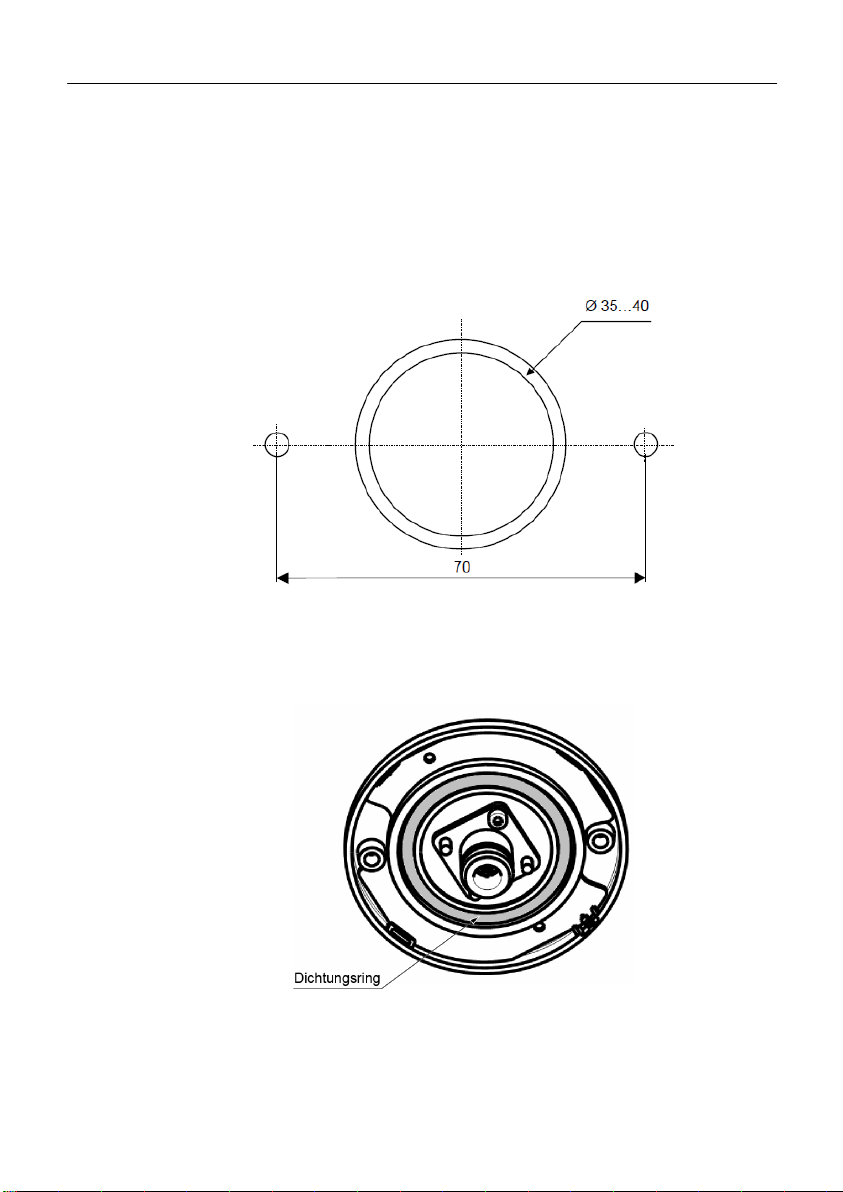
1. Montagebohrungen vorbereiten:
Bohren Sie für den Antennenanschluss ein Rundloch mit einem
Durchmesser von 35-40 mm und für die Antennenbefestigung
zwei Löcher mit Durchmessern von 4,5 mm.
Die Maße entnehmen Sie dem nachfolgenden Bild.
2. Dichtungsring auf richtigen Sitz prüfen:
Prüfen Sie, ob der Dichtungsring an der Antennenunterseite sau-
ber anliegt.
Kompaktbetriebsanleitung ANT795-6MN 11
A5E01116919B-07
Page 12
Deutsch
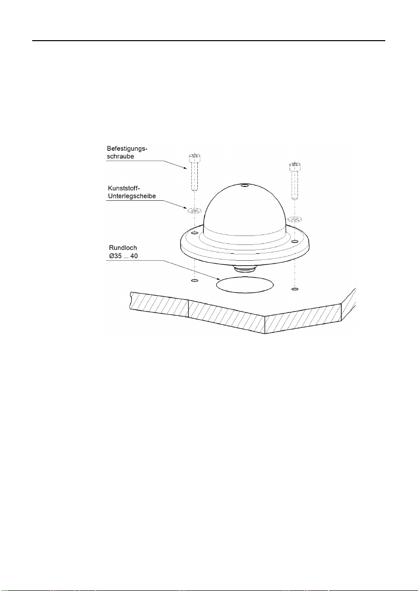
3. Antenne anbringen:
Befestigen Sie die Antenne mit geeigneten Befestigungsschrau-
ben und den mitgelieferten Kunststoff-Unterlegscheiben über zwei
Bohrungen. Das Anzugsmoment beträgt max. 2 Nm.
Stecken Sie die mitgelieferten Abdeckkappen über die Befesti-
gungsschrauben.
12 Kompaktbetriebsanleitung ANT795-6MN
A5E01116919B-07
Page 13
Deutsch
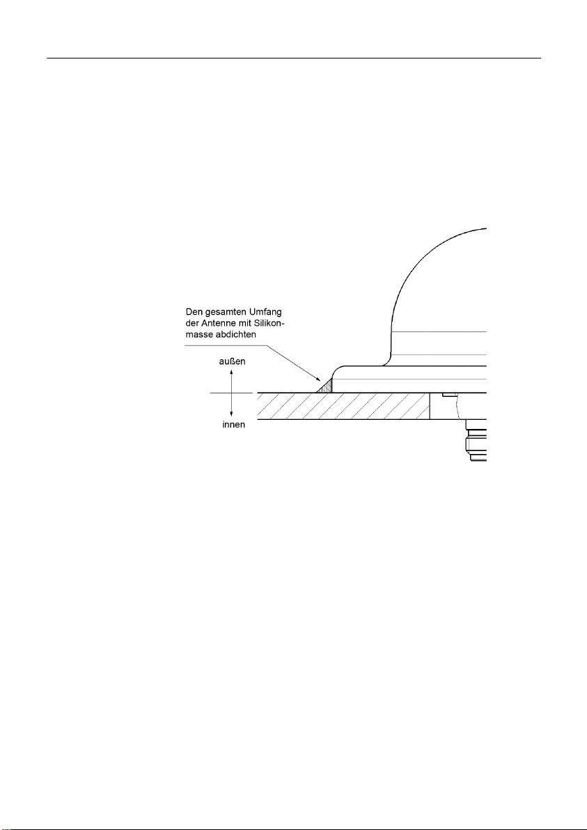
4. Antenne im Außenbereich abdichten:
Wenn die Antenne im Außenbereich montiert wird, müssen Sie
sie abdichten. Gehen Sie wie folgt vor:
Reinigen Sie die Montagefläche mit Alkohol oder einer milden Seifenlösung.
Dichten Sie die Antenne am Außenrand und an den Bohrlöchern
mit Silikon ab. Verwenden Sie ausschließlich eine Einkomponenten-Silikonmasse, die unter Umgebungsbedingungen aushärtet.
Kompaktbetriebsanleitung ANT795-6MN 13
A5E01116919B-07
Page 14

Deutsch
!
Warnung
Lebensgefahr durch
Antennen im Außenbereich müssen sich im Fangbereich eines Blit
ableiters befinden. Stellen Sie sicher, dass für alle von außen eing
führten leitfähigen Systeme die Möglichkeit eines Blitzschutz
Potenzialausgleichs besteht.
Beachten Sie bei der
dingt
die Anforderungen der Normen VDE 0182 bzw. IEC 62305.
Hinweis
Wir empfehlen das wartungsfreie Blitzschutzelement LP798
verwenden.
Ausnahme
Speisung.
In diesem Fall verwenden Sie ausschließl
LP798
5 Anschließen
Geeignete Blitzschutzelemente sind im Zubehörprogramm von
SIMATIC NET Industrial WLAN verfügbar:
• Blitzschutzelement LP798-1N
(Artikel-Nr. 6GK5798-2LP00-2AA6)
• Blitzschutzelement LP798-2N
(Artikel-Nr. 6GK5798-2LP10-2AA6)
Blitzschlag
z-
e-
-
Umsetzung Ihres Blitzschutzkonzepts unbe
: Über die Antennenleitung erfolgt auch eine DC-
ich das Blitzschutzelement
-1N.
14 Kompaktbetriebsanleitung ANT795-6MN
A5E01116919B-07
-2N zu
Page 15

Deutsch
!
Warnung
Lebensgefahr durch Blitzschlag
Der Einbau eines der genannten Blitzschutzelemente zwischen einer
Antenne und einem SCALANCE W700 stellt noch keinen ausreiche
den Schutz gegen Blitzeinschlag dar. Die genannte
mente sind nur im Rahmen eines umfassenden Blitzschutzko
funktionsfähig. Bei Fragen wenden Sie sich an einen qualifizie
Fachbetrieb.
Hinweis
Außenmontage
Schützen Sie die Anschlüsse vor Umwelteinflüssen (z. B. mit selbs
vulkanisierendem Klebeband oder einem Schrumpfschlauch).
Hinweis
Schutzkappen
Bewahren Sie die entnommene
w
n-
n Blitzschutzele-
nzepts
rten
Vorgehensweise
Nehmen Sie die Schutzkappe vom N-Connector der Antenne ab und
schrauben Sie die flexible Verbindungsleitung auf. Das Anzugsmoment am N-Connector beträgt 1,7 Nm.
t-
aufbewahren
Schutzkappe für eine spätere Ver-
endung auf.
Kompaktbetriebsanleitung ANT795-6MN 15
A5E01116919B-07
Page 16

Deutsch
6 Technische Daten
Mechanische Eigenschaften
Gewicht 300 g
Abmessungen
(Durchmesser x Höhe)
Material
Schutzart IP65 (bei korrekter Montage)
Anschluss N-Connector female
Lager- und Betriebstemperatur -40°C ... +80°C
Windfestigkeit 10 N bei 160 km/h
Silikonfrei
Elektrische Eigenschaften
Frequenzbereich
MHz
Antennengewinn 6 dBi 6 dBi 7 dBi 8 dBi
VSWR 1,8
Horizontaler
Strahlungswinkel (3 dB)
Polarisierung Linear und vertikal
86 x 43 mm
Gehäuseoberseite: Polycarbonat
Rückseite: Aluminium
2400 2500
2500 2700
2
3400 3700
2
4900 5935
1,8
360° 360° 360° 150°
Impedanz 50 Ω
16 Kompaktbetriebsanleitung ANT795-6MN
A5E01116919B-07
Page 17

Deutsch
Zulassungen
Das Produkt ANT795-6MN verfügt über die folgenden Zulassungen:
• EN50155
• EN45545-2
• DIN 5510-2 §5.2.2
• BS6853
• EN50121-4
Kompaktbetriebsanleitung ANT795-6MN 17
A5E01116919B-07
Page 18
Deutsch
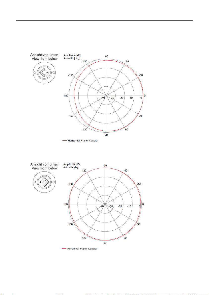
Messung mit Grundfläche ø 1 m:
Messung ohne Grundfläche:
Horizontales Felddiagramm (2450 MHz)
18 Kompaktbetriebsanleitung ANT795-6MN
A5E01116919B-07
Page 19

Deutsch
Vertikales Felddiagramm (2450 MHz)
Messung mit Grundfläche ø 1 m:
Messung ohne Grundfläche:
Kompaktbetriebsanleitung ANT795-6MN 19
A5E01116919B-07
Page 20
Deutsch
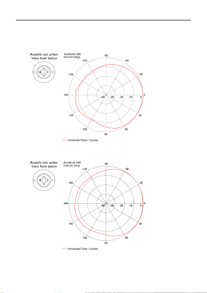
Messung mit Grundfläche ø 1 m:
Messung ohne Grundfläche:
Horizontales Felddiagramm (5150 MHz)
20 Kompaktbetriebsanleitung ANT795-6MN
A5E01116919B-07
Page 21
Deutsch
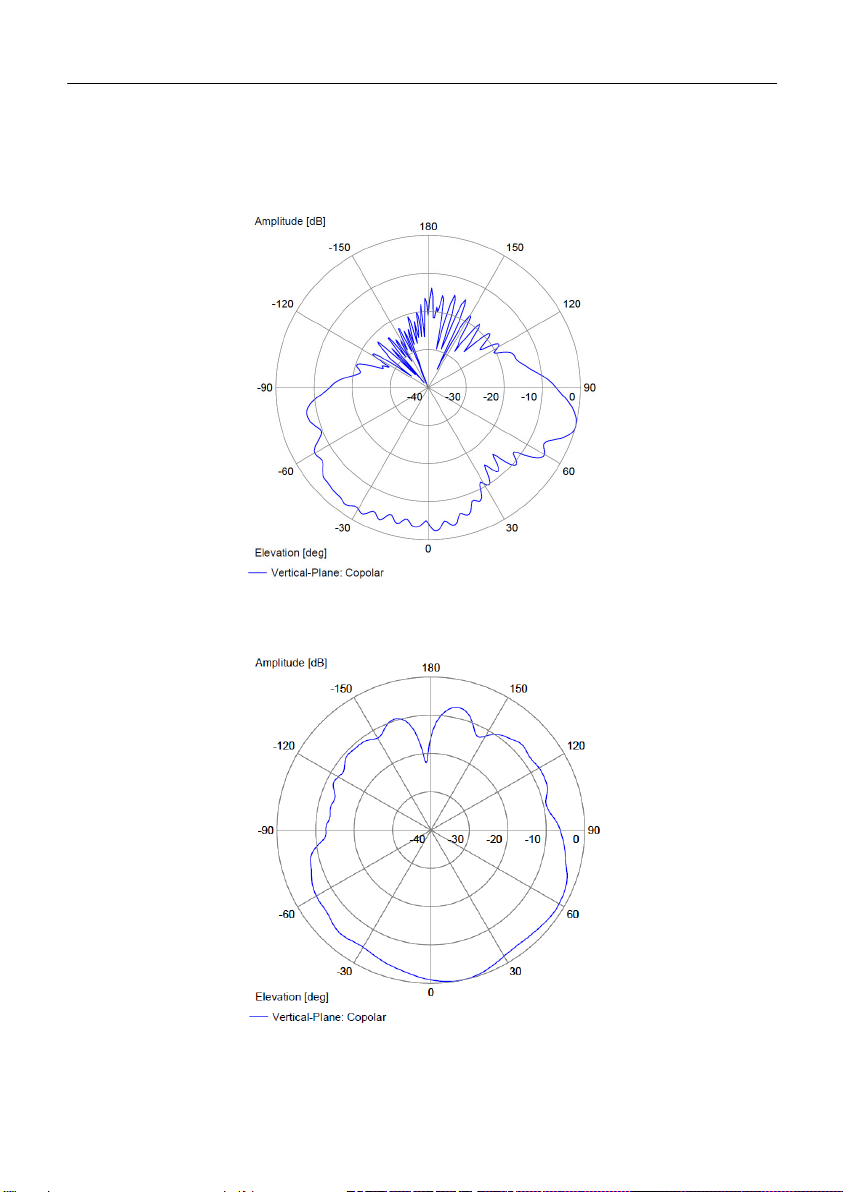
Vertikales Felddiagramm (5150 MHz)
Messung mit Grundfläche ø 1 m:
Messung ohne Grundfläche:
Kompaktbetriebsanleitung ANT795-6MN 21
A5E01116919B-07
Page 22

Deutsch
7 Maßbild
22 Kompaktbetriebsanleitung ANT795-6MN
A5E01116919B-07
Page 23

English
!
Danger
indicates that death or severe personal injury will result if proper
precau
!
Warning
indicates that death or severe personal injury
precautions are not taken.
!
Caution
indicates that minor personal injury can result if proper precautions
are not taken.
Notice
indicates that damage
not taken.
Note
highlights important information on the product, using the product, or
part of the documentation that is of particular importance and that will
be of benefit to the user.
Classification of Safety-Related Notices
This manual contains notices which you should observe to ensure
your own personal safety, as well as to protect the product and
connected equipment. Notices relating to your personal safety are
highlighted by a warning triangle; notices relating to property damage
only do not have a warning triangle. Warnings in descending order
according to the degree of danger are shown as follows.
tions are not taken.
can result if proper
to property can result if proper precautions are
Compact Operating Instructions ANT795-6MN 23
A5E01116919B-07
Page 24

English
Contents
1 General safety notices ........................................................................ 25
2 Description........................................................................................... 27
3 Installation ........................................................................................... 29
4 Connecting up ..................................................................................... 33
5 Technical specifications ..................................................................... 35
6 Dimension drawing ............................................................................. 41
24 Compact Operating Instructions ANT795-6MN
A5E01116919B-07
Page 25

English
!
Warning
Antennas installed outdoors must be within the area covered by a
lightning protection system. Make sure that all conducting systems
entering from outdoors can be protected by a lightning protection
potential equalization system.
When implementing your lightning
adhere to the VDE 0182 or IEC 62305 standard.
!
Warning
The device (and its components) may only be used for the application
described in the catalog or the
combined with devices or components of other manufacturers that
have been approved and released by Siemens.
Correct and safe operation of the device is guaranteed only when it is
transported, stored, set up, installe
to the recommendations.
1 General safety notices
protection concept, make sure you
operating instructions. It may only be
d, used and maintained according
Qualified personnel
Only qualified personnel should be allowed to install and work on
this equipment. Qualified persons in the sense of the safety-related
notices in this manual are defined as persons who are authorized to
commission, to ground, and to tag circuits, equipment, and systems in
accordance with established safety practices and standards.
Compact Operating Instructions ANT795-6MN 25
A5E01116919B-07
Page 26
English
2 Recycling and disposal
Beachten Sie unterschiedliche länderspezifische Regelungen.
The products are low in pollutants, can be recycled and meet the
requirements of the WEEE directive 2012/19/EU for the disposal
of electrical and electronic equipment.
Do not dispose of the products at public disposal sites.
For environmentally friendly recycling and the disposal of your old
device contact a certified disposal company for electronic scrap or
your Siemens contact (Product return https://support.industry.
siemens.com/cs/ww/de/view/109479891).
Note the different national regulations.
26 Compact Operating Instructions ANT795-6MN
A5E01116919B-07
Page 27

English
3 Description
Introduction
The ANT795-6MN antenna is designed especially for roof mounting
on vehicles. You can, however, install it in any position on a fixed,
level and smooth surface.
Scope of delivery
The following components are supplied with the antenna:
• 1x antenna with 1x female N connector
• 1x terminator TI795-1R
• 2x screws
• 2x screw caps
• 2x pins
• 2x sealing washers
• 1x Compact Operating Instructions
Checking the components of the product
1. Check that all components are present.
2. If it is not complete or there are signs of external damage, please
contact your supplier or your local Siemens office.
Compact Operating Instructions ANT795-6MN 27
A5E01116919B-07
Page 28

English
Optional accessories
N-Connect/R-SMA connecting cable
For connection to SCALANCE W700 with R-SMA connectors, the
flexible connecting cable N-Connect/R-SMA Male/Male can be
supplied as an accessory.
Length in m Article number
0,3 6XV1875-5CE30
1 6XV1875-5CH10
2 6XV1875-5CH20
5 6XV1875-5CH50
10 6XV1875-5CN10
N-Connect/ N-Connect connecting cable
For connecting the lightning protection element LP798-1N/LP798-2N
the flexible connecting cable N-Connect/N-Connect Male/Male can be
supplied as an accessory.
Length in m Article number
1 6XV1875-5AH10
2 6XV1875-5AH20
5 6XV1875-5AH50
10 6XV1875-5AN10
There is a control cabinet feedthrough available for IWLAN devices
located in a control cabinet. You will find detailed information in the
catalog IK PI.
28 Compact Operating Instructions ANT795-6MN
A5E01116919B-07
Page 29

English
Hinweis
The roof of the vehicle should have sufficient mechanical stability to
ensure a correct sealing of the antenna.
Mount the antenna on a flat surface only.
Note
IP65 protection applies to the front of the ANT795
Make sure that no f
the rear.
Seal the holes for securing the antenna with a suitable sealing
compound.
4 Installation
General notes
-6MN antenna.
luids can penetrate via the antenna connector on
Optional mounting fittings can be used to mount the ANT795-6MN
antenna below a roof. You will find detailed information in the catalog
IK PI.
Compact Operating Instructions ANT795-6MN 29
A5E01116919B-07
Page 30
English
Procedure
1. Prepare the mounting hole:
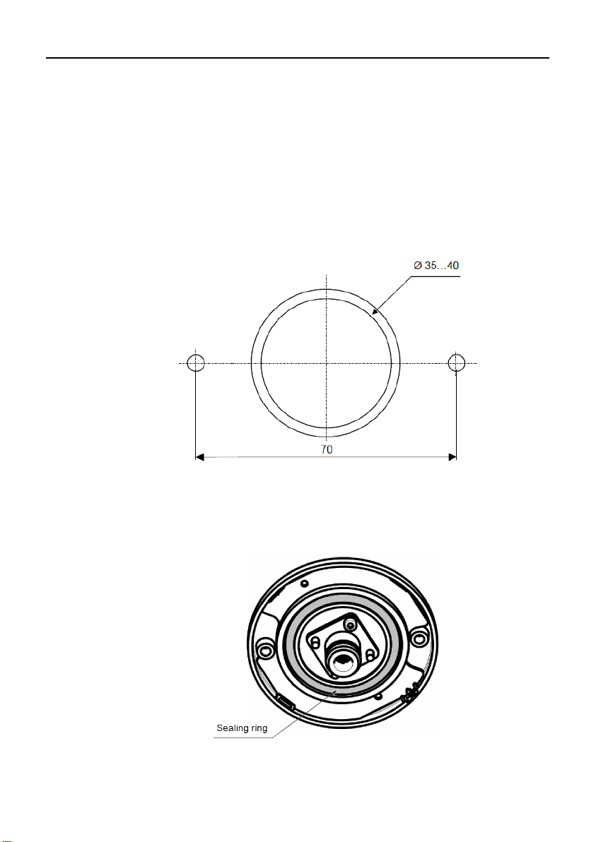
For the antenna connection, drill a round hole with a diameter of
35-40 mm and for the antenna attachment two holes with a
diameter of 4.5 mm.
The dimensions are shown in the following picture.
2. Check the sealing ring for correct seating:
Make sure that the sealing ring on the antenna bottom is
positioned correctly:
30 Compact Operating Instructions ANT795-6MN
A5E01116919B-07
Page 31
English
3. Assembly the antenna:
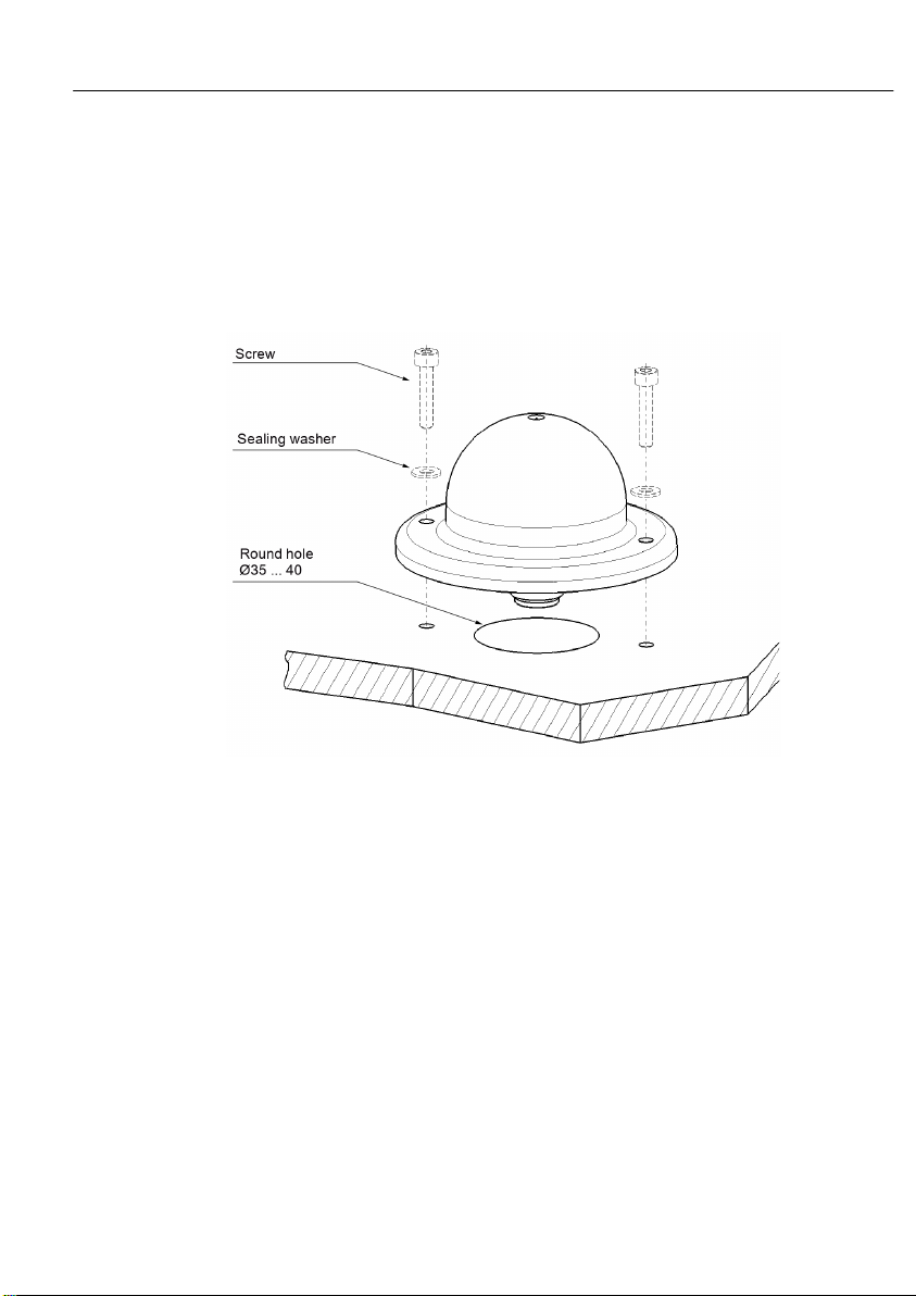
Secure the antenna with two suitable screws and the supplied
sealing washers using two predrilled holes.
The tightening torque is max. 2 Nm.
Insert the supplied screw caps over the screws.
Compact Operating Instructions ANT795-6MN 31
A5E01116919B-07
Page 32
English
4. Seal the antenna in the outdoor area:
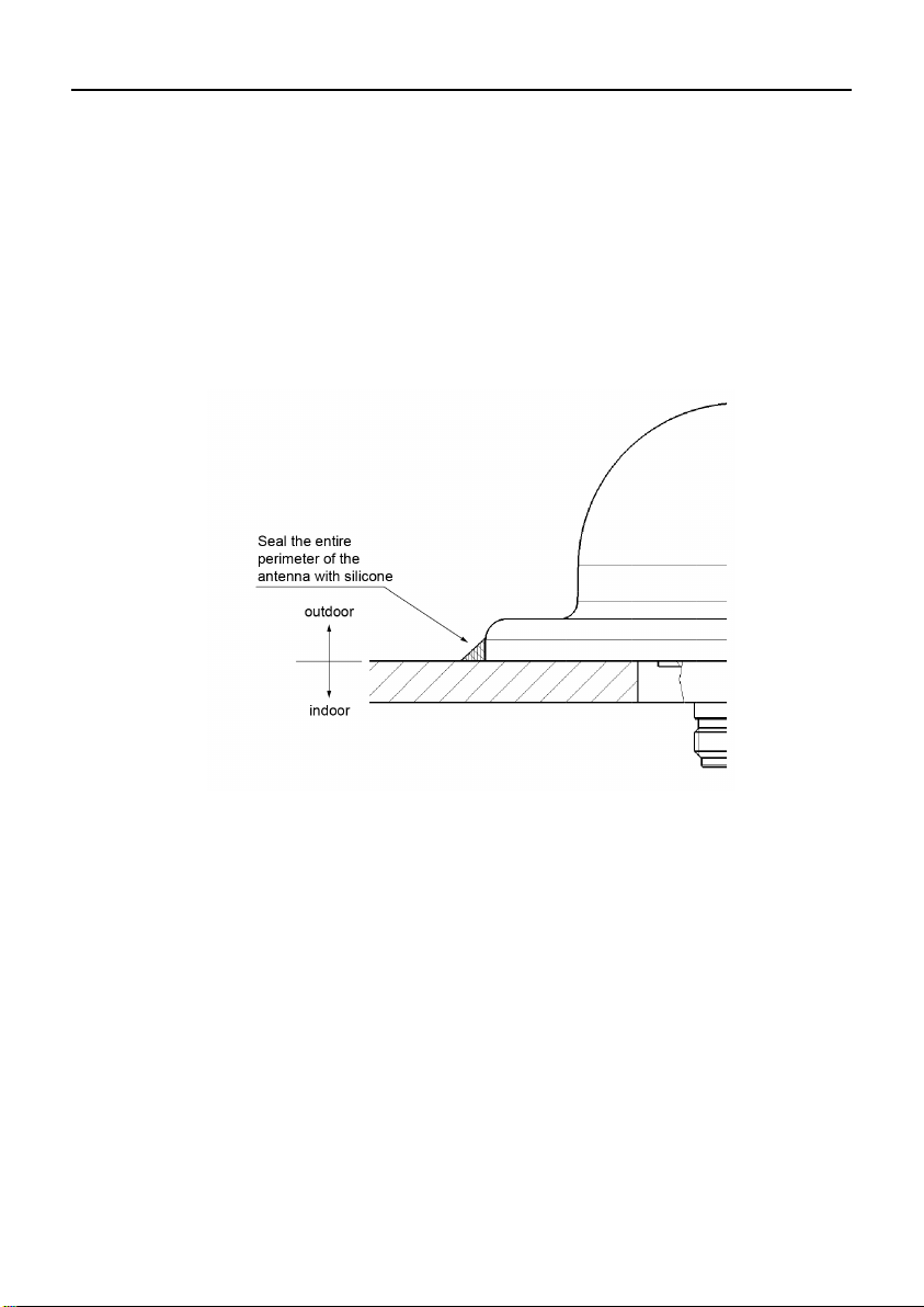
If the antenna is mounted outdoors, you will need to seal it.
Proceed as follows:
Clean the mounting surface with methyl, isopropyl or a mild soap
solution only.
Seal the antenna at the outer edge and at the drill holes with
silicone. Use only one-part silicone sealant that cures by air
humidity.
32 Compact Operating Instructions ANT795-6MN
A5E01116919B-07
Page 33

English
!
Warning
Danger due to lightning strikes
Antennas installed outdoors must be within the area covered by a
lightning protection system. Make sure that all conducting systems
enterin
potential equalization system.
When implementing your lightning protection concept, make sure you
adhere to the VDE 0182 or IEC 62305 standard.
Note
Our recommendation is that you use the maintenance
protector L
Exception:
When there is also DC power supplied via the antenna cable. In this
case, only the lightning protector LP798
5 Connecting up
g from outdoors can be protected by a lightning protection
Suitable lightning conductors are available in the range of accessories
of SIMATIC NET Industrial WLAN:
• Lightning protector LP798-1N
(order no. 6GK5798-2LP00-2AA6)
• Lightning protector LP798-2N
(order no. 6GK5798-2LP10-2AA6
P798-2N.
-1N can be used.
Compact Operating Instructions ANT795-6MN 33
A5E01116919B-07
-free lightning
Page 34

English
!
Warning
Danger due to lightning strikes
Installing this lightning protector between an antenna and a
SCAL
strike. The above
framework of a comprehensive lightning protection concept. If you
have questions, ask a qualified specialist company.
Note
Installation outdoors
Protect the connectors from environmental influences (e.g. with
vulcanizing
Note
Keep the protective caps
Keep protective caps taken out for later use
Procedure
Remove the protective caps from the N connector of the antenna and
screw down the flexible connecting cable. The tightening torque at
the N connector is 1.7 Nm.
ANCE W7xx is not adequate protection against a lightning
-named lightening protectors only work within the
self-
adhesive tape or a shrink-on hose).
.
34 Compact Operating Instructions ANT795-6MN
A5E01116919B-07
Page 35

English
6 Technical specifications
Mechanical properties
Weight 300 g
Dimensions
(diameter x height)
Material
Degree of protection IP65 (when correctly mounted)
Connector N connector female
Storage and operating
temperature
Wind resistance 10 N at 160 km/h
Silicone-free
Electrical properties
Frequency range
MHz
Antenna gain 6 dBi 6 dBi 7 dBi 8 dBi
VSWR 1.8
Horizontal
radiation angle (3 dB)
86 x 43 mm
Top of device: polycarbonate
rear: aluminum
-40°C ... +80°C
2400 2500
2500 2700
2
3400 3700
2
4900 5935
1.8
360° 360° 360° 150°
Polarization Linear and vertical
Impedance 50 Ω
Compact Operating Instructions ANT795-6MN 35
A5E01116919B-07
Page 36

English
Certification
The product ANT795-6MN has the following approvals:
• EN50155
• EN45545-2
• DIN 5510-2 §5.2.2
• BS6853
• EN50121-4
36 Compact Operating Instructions ANT795-6MN
A5E01116919B-07
Page 37

English
Measured with ground plane ø 1 m:
Measured without ground plane:
Horizontal radiation pattern (2450 MHz)
Compact Operating Instructions ANT795-6MN 37
A5E01116919B-07
Page 38

English
Vertical radiation pattern (2450 MHz)
Measured with ground plane ø 1 m:
Measured without ground plane:
38 Compact Operating Instructions ANT795-6MN
A5E01116919B-07
Page 39
English
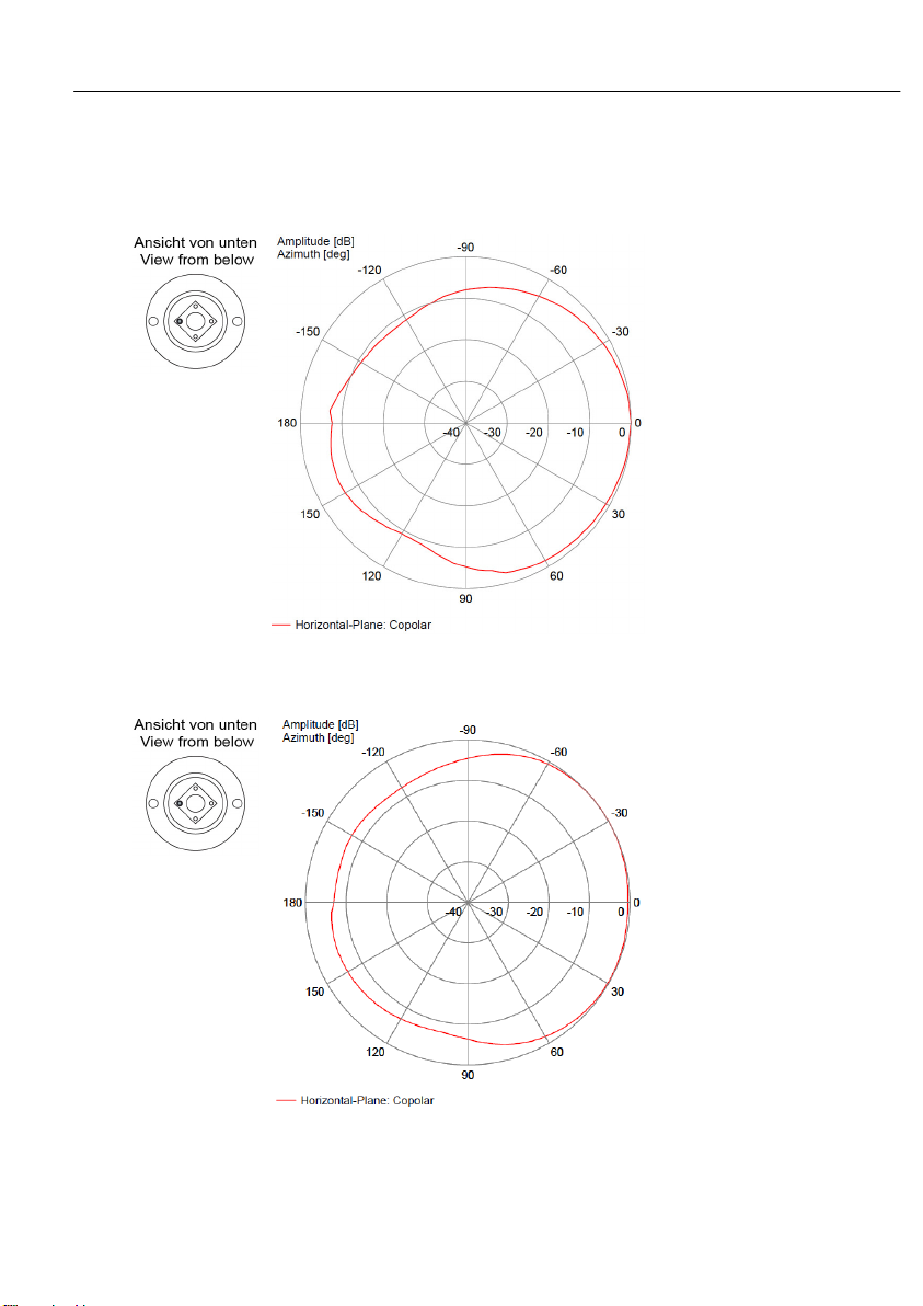
Measured with ground plane ø 1 m:
Measured without ground plane:
Horizontal radiation pattern (5150 MHz)
Compact Operating Instructions ANT795-6MN 39
A5E01116919B-07
Page 40
English
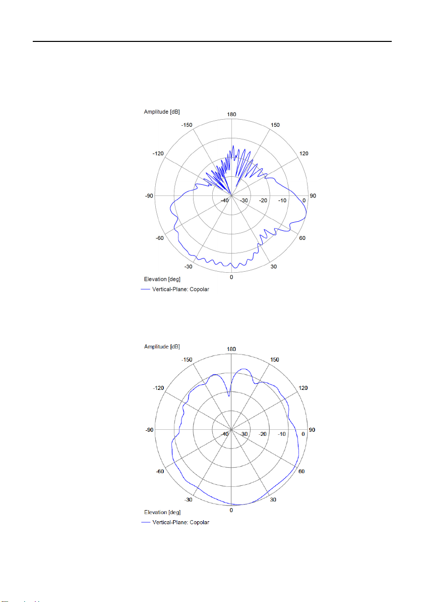
Vertical radiation pattern (5150 MHz)
Measured with ground plane ø 1 m:
Measured without ground plane:
40 Compact Operating Instructions ANT795-6MN
A5E01116919B-07
Page 41
English
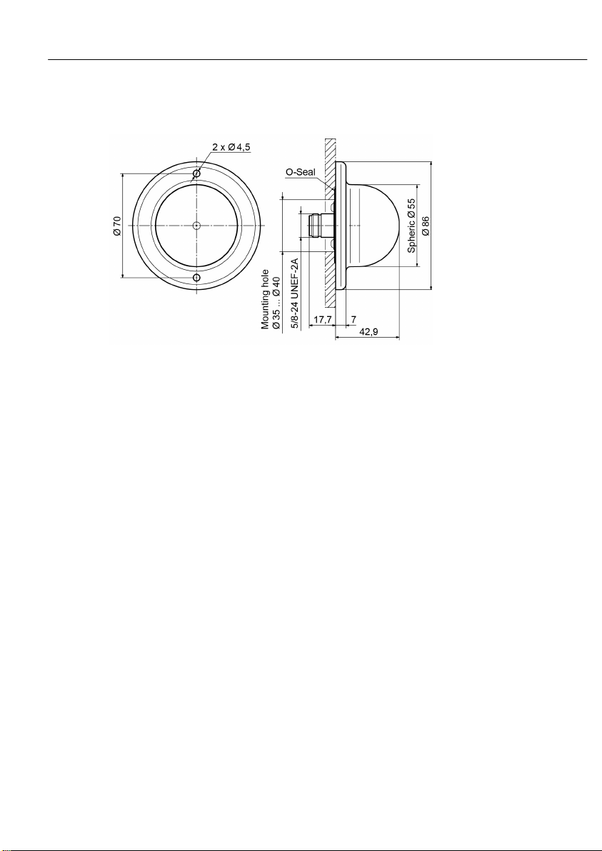
7 Dimension drawing
Compact Operating Instructions ANT795-6MN 41
A5E01116919B-07
Page 42

English
42 Compact Operating Instructions ANT795-6MN
A5E01116919B-07
 Loading...