

Page 1

___________________
___________________
___________________
___________________
___________________
___________________
___________________
___________________
___________________
___________________
___________________
___________________
SIMATIC
Industrial PC
SIMATIC IPC427E
Operating Instructions
09/2017
A5E37454814
Preface
Overview
1
Safety Instructions
2
Installing and connecting the
device
3
Commissioning the device
4
Extended device functions
5
Expanding and assigning
parameters to the device
6
Device maintenance and
repair
7
Technical specifications
8
Technical support
A
Markings and symbols
B
List of abbreviations
C
-AB
Page 2

Siemens AG
Division Digital Factory
Postfach 48 48
90026 NÜRNBERG
GERMANY
A5E37454814-AB
Ⓟ
Copyright © Siemens AG 2017.
All rights reserved
Legal information
Warning notice system
DANGER
indicates that death or severe personal injury will result if proper precautions are not taken.
WARNING
indicates that death or severe personal injury may result if proper precautions are not taken.
CAUTION
indicates that minor personal injury can result if proper precautions are not taken.
NOTICE
indicates that property damage can result if proper precautions are not taken.
Qualified Personnel
personnel qualified
Proper use of Siemens products
WARNING
Siemens products may only be used for the applications described in the catalog and in the relevant technical
maintenance are required to ensure that the products operate safely and without any problems. The permissible
ambient conditions must be complied with. The information in the relevant documentation must be observed.
Trademarks
Disclaimer of Liability
This manual contains notices you have to observe in order to ensure your personal safety, as well as to prevent
damage to property. The notices referring to your personal safety are highlighted in the manual by a safety alert
symbol, notices referring only to property damage have no safety alert symbol. These notices shown below are
graded according to the degree of danger.
If more than one degree of danger is present, the warning notice representing the highest degree of danger will
be used. A notice warning of injury to persons with a safety alert symbol may also include a warning relating to
property damage.
The product/system described in this documentation may be operated only by
task in accordance with the relevant documentation, in particular its warning notices and safety instructions.
Qualified personnel are those who, based on their training and experience, are capable of identifying risks and
avoiding potential hazards when working with these products/systems.
Note the following:
documentation. If products and components from other manufacturers are used, these must be recommended
or approved by Siemens. Proper transport, storage, installation, assembly, commissioning, operation and
All names identified by ® are registered trademarks of Siemens AG. The remaining trademarks in this publication
may be trademarks whose use by third parties for their own purposes could violate the rights of the owner.
We have reviewed the contents of this publication to ensure consistency with the hardware and software
described. Since variance cannot be precluded entirely, we cannot guarantee full consistency. However, the
information in this publication is reviewed regularly and any necessary corrections are included in subsequent
editions.
for the specific
09/2017 Subject to change
Page 3

Preface
Purpose of the Operating Instructions
Basic knowledge required
Scope of the operating instructions
Approbations
CE marking
Standards
Position in the information landscape
These operating instructions contain all the information you need for commissioning and
operating the SIMATIC IPC427E.
It is intended both for programming and testing personnel who commission the device and
connect it with other units (automation systems, programming devices), as well as for service
and maintenance personnel who install add-ons or carry out fault/error analyses.
A solid background in personal computers and Microsoft operating systems is required to
understand this manual. General knowledge in the field automation control engineering is
recommended.
These operating instructions are valid for all versions of the SIMATIC IPC427E.
You will find additional information in "Certificates and approvals (Page 95)".
You will find additional information in "Certificates and approvals (Page 95)".
For more information, refer to sections "Certificates and approvals (Page 95)" and
"Technical specifications (Page 105)".
The IPC documentation comprises:
● SIMATIC IPC427E Quick Install Guide with product information about the device, for
example important notes
SIMATIC IPC427E
Operating Instructions, 09/2017, A5E37454814-AB
● SIMATIC IPC427E Operating Instructions
The documentation is supplied with the IPC in multiple languages in electronic form as a
PDF file on the USB stick supplied in the documentation package.
3
Page 4

Preface
Conventions
Note
A n
specific sections of the documentation that require special consideration.
History
Edition
Comments
09/2016
First edition
Corrections
The terms "PC" and "device" are sometimes used to refer to the SIMATIC IPC427E in this
documentation.
The term "Windows Embedded Standard" is used throughout to refer to "Windows
Embedded Standard 7". "Windows 7" is used as an abbreviation for "Windows 7 Ultimate".
ote is important information about the product, handling the product or a reference to
The following editions of these operating instructions have already been published:
09/2017 Amendment regarding Windows 10
SIMATIC IPC427E
4 Operating Instructions, 09/2017, A5E37454814-AB
Page 5

Table of contents
Preface ................................................................................................................................................... 3
1 Overview................................................................................................................................................. 9
2 Safety Instructions ................................................................................................................................ 17
3 Installing and connecting the device ...................................................................................................... 23
1.1 Product description ................................................................................................................... 9
1.1.1 Applications ............................................................................................................................. 10
1.1.2 Features .................................................................................................................................. 10
1.2 Design of the device ............................................................................................................... 13
1.2.1 Interfaces and operating elements ......................................................................................... 13
1.2.2 Status displays ........................................................................................................................ 14
1.3 Accessories ............................................................................................................................. 15
2.1 General safety instructions ..................................................................................................... 17
2.2 Notes on usage ....................................................................................................................... 21
3.1 Preparing for installation ......................................................................................................... 23
3.1.1 Checking the delivery package ............................................................................................... 23
3.1.2 Identification data of the device .............................................................................................. 25
3.1.3 Permitted mounting positions ................................................................................................. 27
3.2 Installing the device ................................................................................................................ 29
3.2.1 Mounting instructions .............................................................................................................. 29
3.2.2 Installation on a DIN rail .......................................................................................................... 31
3.2.2.1 Attaching the DIN rail bracket ................................................................................................. 31
3.2.2.2 Mounting on DIN rails ............................................................................................................. 32
3.2.3 Wall mounting ......................................................................................................................... 33
3.2.4 Upright mounting ..................................................................................................................... 34
3.3 Connecting the device ............................................................................................................ 35
3.3.1 Notes on connecting ............................................................................................................... 35
3.3.2 Connecting the protective conductor ...................................................................................... 37
3.3.3 Connecting peripheral equipment ........................................................................................... 38
3.3.4 Connecting expansion cards .................................................................................................. 39
3.3.5 Connecting the terminal .......................................................................................................... 40
3.3.6 Connecting the power supply ................................................................................................. 41
3.3.7 Connecting the device to networks ......................................................................................... 42
3.3.8 Installing the strain relief ......................................................................................................... 43
3.3.9 Securing the lines ................................................................................................................... 44
SIMATIC IPC427E
Operating Instructions, 09/2017, A5E37454814-AB
5
Page 6

Table of contents
4 Commissioning the device .................................................................................................................... 45
5 Extended device functions .................................................................................................................... 49
6 Expanding and assigning parameters to the device ............................................................................... 61
7 Device maintenance and repair ............................................................................................................. 73
4.1 General information on commissioning ................................................................................. 45
4.2 Initial commissioning .............................................................................................................. 47
4.3 Windows Action Center .......................................................................................................... 48
4.4 IPC Driver and Tools .............................................................................................................. 48
5.1 Monitoring Functions .............................................................................................................. 49
5.1.1 Overview of the monitoring functions ..................................................................................... 49
5.1.2 Temperature monitoring/display ............................................................................................ 50
5.1.3 Watchdog (WD)...................................................................................................................... 51
5.1.4 Battery monitoring .................................................................................................................. 52
5.1.5 Mass storage monitoring ........................................................................................................ 52
5.2 Unified Write Filter (UWF) ...................................................................................................... 52
5.3 Enhanced Write Filter (EWF) ................................................................................................. 53
5.4 File Based Write Filter (FBWF) .............................................................................................. 56
5.5 Buffer memory NVRAM ......................................................................................................... 58
5.6 Operation without monitor and keyboard ............................................................................... 58
5.7 Active Management Technology (AMT) ................................................................................ 58
5.8 Trusted Platform Modul (TPM) ............................................................................................... 60
6.1 Installing and removing the memory module ......................................................................... 61
6.1.1 Opening the device ................................................................................................................ 61
6.1.2 Opening the device containing expansion cards ................................................................... 63
6.1.3 Replacing memory modules .................................................................................................. 64
6.2 Installing and removing CFast cards...................................................................................... 66
6.3 Installing and removing PCIe cards ....................................................................................... 68
6.4 Assigning CPU power consumption parameters ................................................................... 71
7.1 Maintenance ........................................................................................................................... 73
7.2 Repair information .................................................................................................................. 73
7.3 Installing and removing hardware .......................................................................................... 76
7.3.1 Installing and removing the backup battery ........................................................................... 76
7.3.2 Changing storage media ........................................................................................................ 78
7.3.2.1 Replacing a HDD/SSD ........................................................................................................... 78
7.4 Installing the software ............................................................................................................ 81
7.4.1 Reinstalling the operating system .......................................................................................... 81
7.4.1.1 General installation procedure ............................................................................................... 81
7.4.1.2 Restoring the factory state ..................................................................................................... 83
7.4.1.3 Windows 7 / Windows 10 ....................................................................................................... 84
7.4.1.4 Windows Embedded Standard .............................................................................................. 87
SIMATIC IPC427E
6 Operating Instructions, 09/2017, A5E37454814-AB
Page 7

Table of contents
8 Technical specifications ........................................................................................................................ 95
7.4.2 Partitioning the data storage medium ..................................................................................... 89
7.4.2.1 Partitioning in Windows Embedded Standard 7 ..................................................................... 89
7.4.2.2 Setting up the partitions under Windows 7 Ultimate and Windows 10 ................................... 90
7.4.2.3 Adapting the partitions under Windows 7 Ultimate and Windows 10 ..................................... 91
7.4.3 Installing drivers and software ................................................................................................ 92
7.4.4 Update installation .................................................................................................................. 93
7.4.4.1 Updating the operating system ............................................................................................... 93
7.4.4.2 Installing or updating application programs and drivers ......................................................... 93
7.4.5 Backing up data ...................................................................................................................... 93
7.5 Recycling and disposal ........................................................................................................... 93
8.1 Certificates and approvals ...................................................................................................... 95
8.2 Declaration of conformity ........................................................................................................ 97
8.2.1 CE marking ............................................................................................................................. 97
8.2.2 Electromagnetic compatibility, Industrial and Residential Areas ............................................ 97
8.3 Directives and declarations ..................................................................................................... 98
8.3.1 ESD guideline ......................................................................................................................... 98
8.4 Dimension drawings .............................................................................................................. 101
8.4.1 Dimension drawing - mounting on a DIN rail ........................................................................ 101
8.4.2 Dimension drawing - wall-mounting ...................................................................................... 102
8.4.3 Dimension drawing - vertical mounting ................................................................................. 103
8.4.4 Dimension drawing - device with expansion cards ............................................................... 104
8.5 Technical specifications ........................................................................................................ 105
8.5.1 General technical specifications ........................................................................................... 105
8.5.2 Ambient conditions ................................................................................................................ 108
8.5.3 Power demand of the components ....................................................................................... 110
8.5.4 Integrated DC power supply ................................................................................................. 110
8.5.5 Typical power consumption .................................................................................................. 111
8.6 Hardware descriptions .......................................................................................................... 112
8.6.1 External ports ........................................................................................................................ 112
8.6.1.1 COM1 / COM2 ...................................................................................................................... 112
8.6.1.2 CFast..................................................................................................................................... 113
8.6.1.3 DisplayPort ............................................................................................................................ 114
8.6.1.4 Ethernet ................................................................................................................................ 115
8.6.1.5 USB 3.0 port ......................................................................................................................... 115
8.6.2 Internal ports ......................................................................................................................... 116
8.6.2.1 PCIe card .............................................................................................................................. 116
8.6.3 System resources ................................................................................................................. 118
8.6.3.1 Currently allocated system resources ................................................................................... 118
8.6.3.2 Allocation of system resources ............................................................................................. 118
8.6.4 I/O Address Areas ................................................................................................................. 120
8.6.4.1 Overview of the internal module registers ............................................................................ 120
8.6.4.2 Watchdog enable register / 066h select register (read/write, address 062h) ....................... 120
8.6.4.3 Watchdog trigger register (read only, address 066h) ........................................................... 122
8.6.4.4 Output register user LED L1/L2/L3 (read/write, address 404Eh) ......................................... 122
8.6.4.5 Battery status register (read-only, address 404Dh) .............................................................. 123
8.6.4.6 NVRAM address register ...................................................................................................... 123
SIMATIC IPC427E
Operating Instructions, 09/2017, A5E37454814-AB
7
Page 8

Table of contents
A Technical support................................................................................................................................. 139
B Markings and symbols ......................................................................................................................... 143
C List of abbreviations ............................................................................................................................. 147
Glossary .............................................................................................................................................. 153
Index ................................................................................................................................................... 161
8.7 BIOS description .................................................................................................................. 124
8.7.1 Overview .............................................................................................................................. 124
8.7.2 Opening the BIOS selection menu....................................................................................... 125
8.7.3 Structure of the BIOS Setup menu ...................................................................................... 126
8.7.4 Exit menu ............................................................................................................................. 128
8.7.5 BIOS update ......................................................................................................................... 129
8.7.6 Alarm, error and system messages ..................................................................................... 131
8.8 Active Management Technology (AMT) .............................................................................. 132
8.8.1 Introduction .......................................................................................................................... 132
8.8.2 Overview of AMT.................................................................................................................. 133
8.8.3 Enabling Intel® AMT / basic configuration ........................................................................... 133
8.8.4 Resetting the Intel® AMT to the default settings and disabling AMT .................................. 135
8.8.5 Determining the network address ........................................................................................ 136
8.8.6 Forcing user consent ........................................................................................................... 136
8.9 Functional scope in Windows .............................................................................................. 137
8.9.1 Windows Embedded Standard 7 ......................................................................................... 137
A.1 Service and support ............................................................................................................. 139
A.2 Troubleshooting ................................................................................................................... 140
A.3 Notes on the use of third-party modules .............................................................................. 141
B.1 Overview .............................................................................................................................. 143
B.2 Safety ................................................................................................................................... 143
B.3 Operator controls ................................................................................................................. 143
B.4 Certificates, approvals and markings ................................................................................... 144
B.5 Interfaces ............................................................................................................................. 145
SIMATIC IPC427E
8 Operating Instructions, 09/2017, A5E37454814-AB
Page 9
1
1.1
Product description
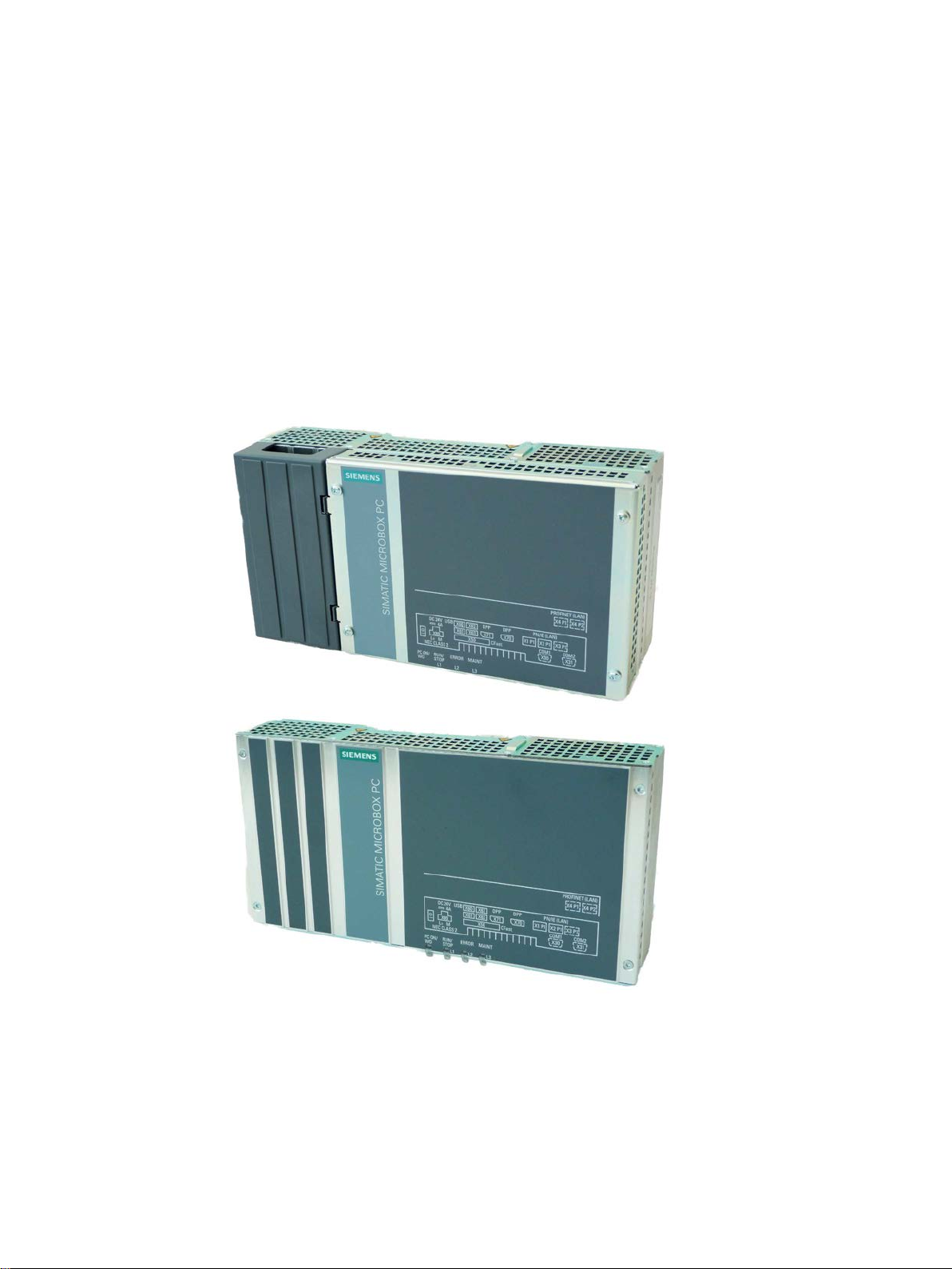
The SIMATIC IPC427E provides high-level industrial functionality.
● Compact design
● Maintenance-free operation
● High degree of ruggedness
SIMATIC IPC427E
Operating Instructions, 09/2017, A5E37454814-AB
9
Page 10

Overview
1.1.1
Applications
1.1.2
Features
Basic data
cards
max. 175 mm long
Power supply
24 V DC (-20%/+20%) max. 4 A
Conditions of use
Operation without fan
1.1 Product description
The device provides industrial PC systems for high-performance and space-saving
applications in particular in the field of machine, systems and switchgear cabinet
engineering:
● Measuring and controlling process and machine data, for example, automated washing
systems, assembling machines and packaging machines
● Operating and visualization tasks with separate monitors or displays, for example,
information terminals and large-scale displays in automotive production
● Data logging and processing, for example, system data logging and distributed process
control
Installation
Processor
Main memory
Free slots for expansion
Graphics
• Installation on a DIN rail
• Wall mounting
• Vertical mounting
• Intel® Celeron® Processor G3902E (2M Cache, 1.6 GHz)
• Intel® Core™ i3-6102E Processor (3M Cache, 1.9 GHz)
• Intel® Core™ i5-6442EQ Processor (6M Cache, up to 2.7 GHz)
• Intel® Xeon® Processor E3-1505L v5 (8M Cache, up to 2.8 GHz)
Memory modules without ECC:
• 4 GB DDR4-SDRAM SODIMM
• 8 GB DDR4-SDRAM SODIMM
• 16 GB DDR4-SDRAM SODIMM
Memory module with ECC (not combinable with i5 CPU):
• 8 GB DDR4-SDRAM SODIMM
• 16 GB DDR4-SDRAM SODIMM
Up to 2 × PCIe cards (optional), depending on enclosure version;
• Intel® HD Graphics 510 / 530 / P530 (depending on CPU type)
• 2 x DisplayPort, maximum resolution 4096 x 2304 pixels
• Graphics memory is claimed in main memory (dynamic UMA)
SIMATIC IPC427E
10 Operating Instructions, 09/2017, A5E37454814-AB
Page 11

Overview
Basic data
Drives and storage media
Hard disk
2.5", ≥ 320 GB, SATA (optional)
SSD (Solid State Disk)
2.5", ≥ 80 GB SATA (optional)
USB stick
External, can be connected via USB interface
Ports
Serial
COM1 / COM2 (RS 232, RS 422, RS 485 configurable), optional
Graphics
2 x DisplayPort DPP (DVI via DP++ to DVI adapter possible)
backward compatible with USB 2.0/1.1
Ethernet
2 × (3 x optional) RJ45 (10/100/1000 Mbps), teaming-capable
Keyboard, mouse
Connected via external USB port
Extended device functions
grammed by the user
Transient voltage interruption
Up to 15 ms buffer time at full load
Buffer memory
512 KB optional
standard
1.1 Product description
CFast card Can be used optionally as boot drive or additional data memory.
• 2 GB
• 4 GB
• 8 GB
• 16 GB
• 30 GB
USB 4 × USB 3.0, simultaneous operation of max. 2 x high current ports,
Temperature monitoring
• When permitted temperature range is exceeded
• Warnings can be analyzed by application program (local, via LAN)
Watchdog
• Monitoring function for program execution
• Restart can be parameterized in the event of a fault
• Warnings can be analyzed by application program (local, via LAN)
LED display 4 LEDs for displaying system statuses; 3 of these can be freely pro-
TPM Integrated Trusted Platform Module, optional, according to TPM 2.0
SIMATIC IPC427E
Operating Instructions, 09/2017, A5E37454814-AB
11
Page 12

Overview
Software
Operating systems
1.1 Product description
Available
Project-specific
• None
• Windows Embedded Standard 7, SP1
• Windows 7 Ultimate, SP1
• Windows 10 IoT Enterprise LTSB 2016, 64-bit
• LINUX
• QNX
• VxWorks
SIMATIC IPC427E
12 Operating Instructions, 09/2017, A5E37454814-AB
Page 13

Overview
1.2
Design of the device
1.2.1
Interfaces and operating elements
①
"OFF", when the "_" symbol is pressed. Position "OFF" is the delivery state.
②
24V DC
Power supply connection
③
Protective conductor
Protective conductor terminal
④
Memory card slot
Slot for CFast card with cover
⑤
4 × USB
USB 3.0 high current, backward compatible with USB 2.0/1.1
⑥
2 x DisplayPort
DisplayPort connection for digital monitor
⑦
3 × Ethernet / 2 x Ethernet
RJ45 interface (10/100/1000 Mbps); 2 x RJ45 (optional)
⑧
COM1
Serial interface (optional)
⑨
COM2
Serial interface (optional)
1.2 Design of the device
On/off switch The on/off switch does not isolate the device from the power supply. Position
SIMATIC IPC427E
Operating Instructions, 09/2017, A5E37454814-AB
13
Page 14

Overview
1.2.2
Status displays
LED
State
Description
Green
BIOS ready to boot; PC running
(1 Hz)
Yellow
Idle state
Flashing red (1 Hz)
Watchdog status display: active
Off
-
Green
Can be controlled by user program
WinAC)
Off - Red
-
program (e.g. WinAC)
Off
-
Yellow
-
WinAC)
1.2 Design of the device
PC ON/WD Off -
Flashing green/yellow
RUN/STOP / L1
Yellow Can be controlled by controller program (e.g.
ERROR / L2
Flashing red Can be controlled by user program or controller
MAINT / L3
Red Can be controlled by controller program (e.g.
BIOS in POST, power switch on
For additional information on controlling the LEDs or the NVRAM with a Windows operating
system, please refer to Output register user LED L1/L2/L3 (read/write, address 404Eh)
(Page 122). Example programs for controlling the LEDs on Windows operating systems are
available on the Customer Support page of Siemens Industry Automation and Drive
Technologies. (http://www.siemens.com/automation/service&support)
SIMATIC IPC427E
14 Operating Instructions, 09/2017, A5E37454814-AB
Page 15

Overview
1.3
Accessories
SIMATIC IPC CFast cards
Memory modules
Mounting sets
1.3 Accessories
Siemens offers accessories not included in the scope of delivery for the device. For more
information on available accessories, refer to the Internet at:
Industry Mall (https://mall.industry.siemens.com)
Expansion components and accessories (http://www.automation.siemens.com/mcms/pc-
based-automation/en/industrial-pc/expansion_components_accessories)
● 2 GB optional or
● 4 GB optional or
● 8 GB optional or
● 16 GB optional or
● 30 GB optional
● SO-DIMM module 4096 MB DDR4-SDRAM
● SO-DIMM module 8192 MB DDR4-SDRAM
● SO-DIMM module 16384 MB DDR4-SDRAM
● SO-DIMM module 8192 MB DDR4-SDRAM ECC
● SO-DIMM module 16384 MB DDR4-SDRAM ECC
● Mounting onto standard rail
● Wall mounting
● Vertical mounting
SIMATIC IPC427E
Operating Instructions, 09/2017, A5E37454814-AB
15
Page 16

Overview
1.3 Accessories
SIMATIC IPC427E
16 Operating Instructions, 09/2017, A5E37454814-AB
Page 17

2
2.1
General safety instructions
WARNING
Life-threatening voltages are present with an open control cabinet
System expansions
NOTICE
Damage through system expansions
When you install the device in a control cabinet, some areas or components in the open
control cabinet may be carrying life-threatening voltages.
If you touch these areas or components, you may be killed by electric shock.
Switch off the power supply to the cabinet before opening it.
Device and system expansions may be faulty and can affect the entire machine or plant.
The installation of expansions can damage the device, machine or plant. Device and
system expansions may violate safety rules and regulations regarding radio interference
suppression. If you install or exchange system expansions and damage your device, the
warranty becomes void.
SIMATIC IPC427E
Operating Instructions, 09/2017, A5E37454814-AB
17
Page 18

Safety Instructions
NOTICE
"Open Type" UL508
WARNING
Risk of fire through expansion cards
Battery and rechargeable battery
WARNING
Risk of explosion and release of harmful substances
2.1 General safety instructions
Note the following for system expansions:
● Only install system expansion devices designed for this device. Contact your technical
support team or where you purchased your PC to find out which system expansion
devices may safely be installed.
● Observe the information on electromagnetic compatibility (Page 97).
Note that the device is classified as "Open Type" for use in the area of Industrial Control
Equipment (UL508). Installation of the device in an enclosure complying with UL508 for
specific permitted mounting positions (see corresponding section) is a prerequisite for
approval or operation in accordance with UL508.
Expansion cards generate additional heat. The device may overheat and cause a fire.
Please note the following:
• Observe the safety and installation instructions for the expansion cards.
• If in doubt, install the device in an enclosure that is compliant with sections 4.6 and 4.7.3
of the IEC/UL/EN/DIN-EN 60950-1 standard.
Improper handling of lithium batteries can result in an explosion of the batteries.
Explosion of the batteries and the released pollutants can cause severe physical injury.
Worn batteries jeopardize the function of the device.
Note the following when handling lithium batteries:
• Replace used batteries in good time; see the section "Replacing the backup battery" in
the operating instructions.
• Replace the lithium battery only with an identical battery or types recommended by the
manufacturer (order no.: A5E34734290).
• Do not throw lithium batteries into fire, do not solder on the cell body, do not recharge,
do not open, do not short-circuit, do not reverse polarity, do not heat above 100°C and
protect from direct sunlight, moisture and condensation.
SIMATIC IPC427E
18 Operating Instructions, 09/2017, A5E37454814-AB
Page 19

Safety Instructions
High frequency radiation
NOTICE
Unintentional operating situations
ESD Guideline
NOTICE
Electrostatic sensitive devices (ESD)
Industrial Security
2.1 General safety instructions
High frequency radiation, e g. from a cellular phone, interferes with device functions and
can result in malfunctioning of the device.
Persons are injured and the plant is damaged.
Avoid high-frequency radiation:
• Remove radiation sources from the environment of the device.
• Switch off radiating devices.
• Reduce the radio output of radiating devices.
• Observe the information on electromagnetic compatibility (Page 97).
Electrostatic sensitive devices can be labeled with an appropriate symbol.
When you touch electrostatic sensitive components, you can destroy them through voltages
that are far below the human perception threshold.
If you work with components that can be destroyed by electrostatic discharge, observe the
ESD Guideline (Page 98).
Siemens provides products and solutions with industrial security functions that support the
secure operation of plants, systems, machines and networks.
In order to protect plants, systems, machines and networks against cyber threats, it is
necessary to implement – and continuously maintain – a holistic, state-of-the-art industrial
security concept. Siemens’ products and solutions only form one element of such a concept.
Customer is responsible to prevent unauthorized access to its plants, systems, machines
and networks. Systems, machines and components should only be connected to the
enterprise network or the internet if and to the extent necessary and with appropriate security
measures (e.g. use of firewalls and network segmentation) in place.
Additionally, Siemens’ guidance on appropriate security measures should be taken into
account. For more information about industrial security, please visit
(http://www.siemens.com/industrialsecurity).
SIMATIC IPC427E
Operating Instructions, 09/2017, A5E37454814-AB
19
Page 20

Safety Instructions
Disclaimer for third-party software updates
Notes on protecting administrator accounts
2.1 General safety instructions
Siemens’ products and solutions undergo continuous development to make them more
secure. Siemens strongly recommends to apply product updates as soon as available and to
always use the latest product versions. Use of product versions that are no longer supported,
and failure to apply latest updates may increase customer’s exposure to cyber threats.
To stay informed about product updates, subscribe to the Siemens Industrial Security RSS
Feed under (https://support.industry.siemens.com).
This product includes third-party software. Siemens AG only provides a warranty for
updates/patches of the third-party software, if these have been distributed as part of a
Siemens software update service contract or officially released by Siemens AG. Otherwise,
updates/patches are undertaken at your own risk. You can find more information about our
Software Update Service offer on the Internet at Software Update Service
(http://www.automation.siemens.com/mcms/automation-software/en/software-update-
service).
A user with administrator privileges has extensive access and manipulation options in the
system.
Therefore, ensure there are adequate safeguards for protecting the administrator accounts
to prevent unauthorized changes. To do this, use secure passwords and a standard user
account for normal operation. Other measures, such as the use of security policies, should
be applied as needed.
SIMATIC IPC427E
20 Operating Instructions, 09/2017, A5E37454814-AB
Page 21

Safety Instructions
2.2
Notes on usage
WARNING
Risks associated with the unprotected machine or plant
Environment
NOTICE
Ambient conditions and chemical resistance
2.2 Notes on usage
According to the results of a risk analysis, certain hazard potentials associated with the
unprotected machine exist. These hazards could lead to personal injury.
Avoid such hazards by taking the following precautions in accordance with the risk analysis:
• Installation of additional safety equipment on the machine or plant. In particular, the
programming, parameter assignment and wiring of the inserted I/O modules must be
executed in accordance with the safety performance identified by the necessary risk
analysis (SIL, PL or Cat.).
• Use as intended must be validated for the device by means of a function test on the
plant. These tests help you to identify programming, parameter assignment and wiring
errors.
• Documentation of the test results that you can enter in the relevant safety verification
documents, if necessary.
Unsuitable environmental conditions have a negative impact on device operation. Chemical
substances such as cleaners or fuels may alter the color, shape and structure of the device
surface, for example, the front panel.
The device may be damaged. possibly resulting in malfunctions.
For this reason, please observe the following precautions:
• Always operate the device in closed rooms. All warranties shall be void in the case of
noncompliance.
• Operate the device only in accordance with the ambient conditions specified in the
technical specifications.
• Protect the device against dust, moisture and heat.
• Do not expose the device to direct sunlight or to other strong sources of light.
• Without additional safety measures, such as a supply of clean air, the device may not be
used in locations with harsh operating conditions caused by acidic vapors or gases.
• Observe the permitted mounting positions of the device.
• Do not obstruct the venting slots of the device.
• Always use suitable cleaning agents. Read the information about Chemical resistance of
the HMI devices and industrial PCs
(http://support.automation.siemens.com/WW/view/en/39718396) on the Internet.
SIMATIC IPC427E
Operating Instructions, 09/2017, A5E37454814-AB
21
Page 22

Safety Instructions
Note
Use in an industrial environment without additional protective measures
The device has been designed for use in a normal industrial environment in
IEC
2.2 Notes on usage
accordance with
60721-3-3 (pollutant class 3C2 for chemical influences, 3S2 for dust without sand).
SIMATIC IPC427E
22 Operating Instructions, 09/2017, A5E37454814-AB
Page 23

3
3.1
Preparing for installation
3.1.1
Checking the delivery package
Procedure
Note
Damage to the device during transport and storage
If a device is transported or stored without packaging, shocks, vibrations, pressure and
moisture may impact the unprotected unit. Damaged packaging indicates that ambient
conditions have already had a massive impact on
This may cause the device, machine or plant to malfunction.
•
•
1. When accepting a delivery, please check the packaging for visible transport damage.
2. If any transport damage is present at the time of delivery, lodge a complaint at the
shipping company in charge. Have the shipper confirm the transport damage
immediately.
3. Unpack the device at its installation location.
4. Keep the original packaging in case you have to transport the unit again.
the device and it may be damaged.
Keep the original packaging.
Pack the device in the original packaging for transportation and storage.
5. Check the contents of the packaging and any accessories you may have ordered for
completeness and damage.
SIMATIC IPC427E
Operating Instructions, 09/2017, A5E37454814-AB
23
Page 24

Installing and connecting the device
WARNING
Electric shock and fire hazard due to damaged device
NOTICE
Damage from condensation
3.1 Preparing for installation
6. Please inform the delivery service immediately if the package contents are incomplete or
damaged or do not correspond with your order. Fax the enclosed form "SIMATIC IPC/PG
Quality Control Report".
A damaged device can be under hazardous voltage and trigger a fire in the machine or
plant. A damaged device has unpredictable properties and states.
Death or serious injury could occur.
Make sure that the damaged device is not inadvertently installed and put into operation.
Label the damaged device and keep it locked away. Send off the device for immediate
repair.
If the device is subjected to low temperatures or extreme fluctuations in temperature
during transportation, as is the case in cold weather, for example, moisture can build up
on or inside the device (condensation).
Moisture causes a short circuit in electrical circuits and damages the device.
In order to prevent damage to the device, proceed as follows:
• Store the device in a dry place.
• Bring the device to room temperature before starting it up.
• Do not expose the device to direct heat radiation from a heating device.
• If condensation develops, wait approximately 12 hours or until the device is
completely dry before switching it on.
7. Please keep the enclosed documentation in a safe place. It belongs to the device. You
need the documentation when you commission the device for the first time.
8. Write down the identification data of the device.
SIMATIC IPC427E
24 Operating Instructions, 09/2017, A5E37454814-AB
Page 25

Installing and connecting the device
3.1.2
Identification data of the device
Unpacking the device
Identification date
Source
Value
Serial number
Rating plate
S VP ...
have COA labels
Ethernet address 1
Ethernet address 2
Ethernet address 3 (optional)
Rating plate
3.1 Preparing for installation
The device can be identified uniquely with the help of these numbers in case of repairs or
theft.
Enter the identification data in the table below:
Article number of the device Rating plate 6AG4141-...
Microsoft Windows Product Key
Certificate of Authenticity (COA)
Side surface of
the device
BIOS setup, "Advanced" menu
Only devices with preinstalled
Windows operating systems
SIMATIC IPC427E
Operating Instructions, 09/2017, A5E37454814-AB
25
Page 26

Installing and connecting the device
Example of a COA label
3.1 Preparing for installation
Microsoft Windows "Product Key" of the "Certificate of Authenticity" (COA):
The COA label is only attached to the side of the device when a Windows operating system
is installed.
● COA label of a device with the Windows Embedded Standard 7 operating system
● COA label of a device with Windows 7 operating system
● COA label of a device with Windows 10 operating system
The Windows 10 COA label has an additional security feature which conceals part of the
product key.
The scratch-off panel consists of a small transparent label with a silver-colored scratch
coating, which was applied to conceal part of the 25-character product key. This scratchoff panel is designed to protect the product key from being obtained and used by
unauthorized third parties.
You usually do not need this product key for commissioning because a valid product key
has already been integrated into the pre-installed operating system.
SIMATIC IPC427E
26 Operating Instructions, 09/2017, A5E37454814-AB
Page 27
Installing and connecting the device
3.1.3
Permitted mounting positions
Note
The device is only approved for operation in closed
Ensure that the required minimum clearance to other components or enclosure panels is
maintained.
With horizontal mounting position:
•
•
•
With vertical mounting position and portr
•
•
•
NOTICE
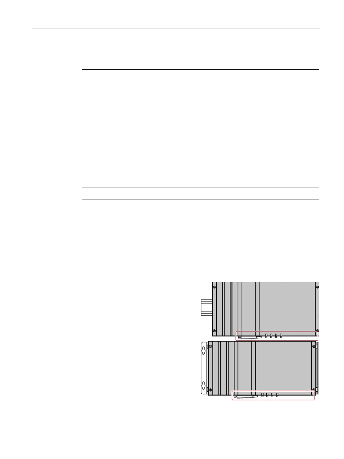
Points to note with expansion cards
Installation on a DIN rail
The interfaces are at the bottom.
Wall mounting
The interfaces are at the bottom.
3.1 Preparing for installation
rooms.
Underneath at least 100 mm
Above at least 50 mm
At least 50 mm at the side
ait mounting:
Underneath at least 50 mm
Above at least 50 mm
At least 50 mm at the side
Expansion cards may impose restrictions on the installation location (fire-proof enclosure)
and permitted mounting positions (see Technical specifications). If the device has been
fitted with expansion cards, please observe the safety and installation instructions for the
expansion cards in the corresponding documentation.
If in doubt, install the device in an enclosure that is compliant with IEC/UL/EN/
DIN-EN 60950-1, sections 4.6 and 4.7.3.
Horizontal mounting is the preferred position. The horizontal mounting options are as follows:
SIMATIC IPC427E
Operating Instructions, 09/2017, A5E37454814-AB
27
Page 28

Installing and connecting the device
Wall mounting
The interfaces are at
the left.
Vertical mounting
The interfaces are
at the front. The
power supply co
nection is at the
top.
3.1 Preparing for installation
The device can be mounted vertically on DIN rails or on the wall. The figure shows the
interfaces on the front.
The vertical mounting options are as follows:
n-
Observe the permitted temperature range for operation in the respective mounting position
as defined in "Technical specifications (Page 105)".
SIMATIC IPC427E
28 Operating Instructions, 09/2017, A5E37454814-AB
Page 29

Installing and connecting the device
3.2
Installing the device
3.2.1
Mounting instructions
Securing the device
NOTICE
Insufficient load carrying capacity
NOTICE
Incorrect fixing elements
3.2 Installing the device
Note the following:
● The device is only approved for operation in closed rooms.
● For installation in a control cabinet, observe the SIMATIC installation guidelines and
applicable DIN/VDE requirements or other applicable country-specific regulations.
● When the device is used in the area of Industrial Control Equipment in accordance with
UL508, note that the device is classified as "Open Type". The installation of the device in
a housing conforming to UL508 is therefore a mandatory requirement for approval or
operation in accordance with UL508.
If the wall it is mounted on does not have a sufficient load-bearing capacity, the device may
fall and be damaged.
Ensure that the mounting surface on the wall can bear four times the total weight of the
device, including fixing elements.
The device may not be securely fitted if you use anchors and screws other than those
specified below for mounting. The device can fall and may be damaged.
Use only the anchors and screws specified in the following table.
SIMATIC IPC427E
Operating Instructions, 09/2017, A5E37454814-AB
29
Page 30

Installing and connecting the device
Material
Bore diameter
Fastener
min. 13 mm thickness
Material
Bore diameter
Fastener
min. 13 mm thickness
Material
Bore diameter
Fastener
min. 13 mm thickness
3.2 Installing the device
Use the following fasteners:
● Installation on a DIN rail
Metal,
min. 2 mm thickness
Concrete 6 mm, 40 mm depth
5 mm
• 2 x M4 screws
• 2 x M4 nuts
• 4 x dowels, ∅ 6 mm, 40 mm length
• 4 x screws, ∅ 4 mm, 40 mm length
Plasterboard,
14 mm 4 x toggle bolts, ∅ 4 mm, 50 mm length
● Wall mounting
Concrete 6 mm, 40 mm depth
• 4 x dowels, ∅ 6 mm, 40 mm length
• 4 x screws, ∅ 4 mm, 40 mm length
Plasterboard,
14 mm 4 x toggle bolts, ∅ 4 mm, 50 mm length
● Vertical mounting
Concrete 6 mm, 40 mm depth
8 mm, 40 mm deep
Plasterboard,
14 mm Toggle bolt, ∅ 4 mm, 50 mm length
• 4 x dowels, ∅ 6 mm, 40 mm length
• 4 x screws, ∅ 4 mm, 40 mm length
• Dowel, ∅ 8 mm, 40 mm length
• Screw, ∅ 5 mm, 40 mm length
SIMATIC IPC427E
30 Operating Instructions, 09/2017, A5E37454814-AB
Page 31

Installing and connecting the device
3.2.2
Installation on a DIN rail
3.2.2.1
Attaching the DIN rail bracket
Requirement
Procedure
1. Fasten the DIN rail clip with four screws.
3.2 Installing the device
Before you can install the device on a DIN rail, you will need to attach the DIN rail clip to the
device.
The fasteners and screws required are supplied with the device for the selected mounting
option (as specified in order number).
● 1 DIN rail clip
● 4 screws
● 1 T20 screwdriver
SIMATIC IPC427E
Operating Instructions, 09/2017, A5E37454814-AB
31
Page 32

Installing and connecting the device
3.2.2.2
Mounting on DIN rails
Requirement
Note
Ensure that the wall or ceiling can hold four times the total weight of the device including DIN
profile rail and additional expansion cards. See
Procedure
Installation
1. Place the device and rail clip on the u
per edge of the standard profile rail at the
position shown.
2. Push down the device. Once the rail clip
is over the bottom edge of the
profile rail, push the device towards the
standard profile rail. You will hear the
device click into place.
Removal
3.2 Installing the device
● DIN rail, 35 mm standard profile
The DIN rail is installed at the installation site.
Mounting instructions (Page 29).
p-
standard
1. Push down the device until it is released by the rail clips.
2. Swing the device out of the standard profile rail.
3. Lift the device up and off.
SIMATIC IPC427E
32 Operating Instructions, 09/2017, A5E37454814-AB
Page 33
Installing and connecting the device
3.2.3
Wall mounting
Requirement
Procedure
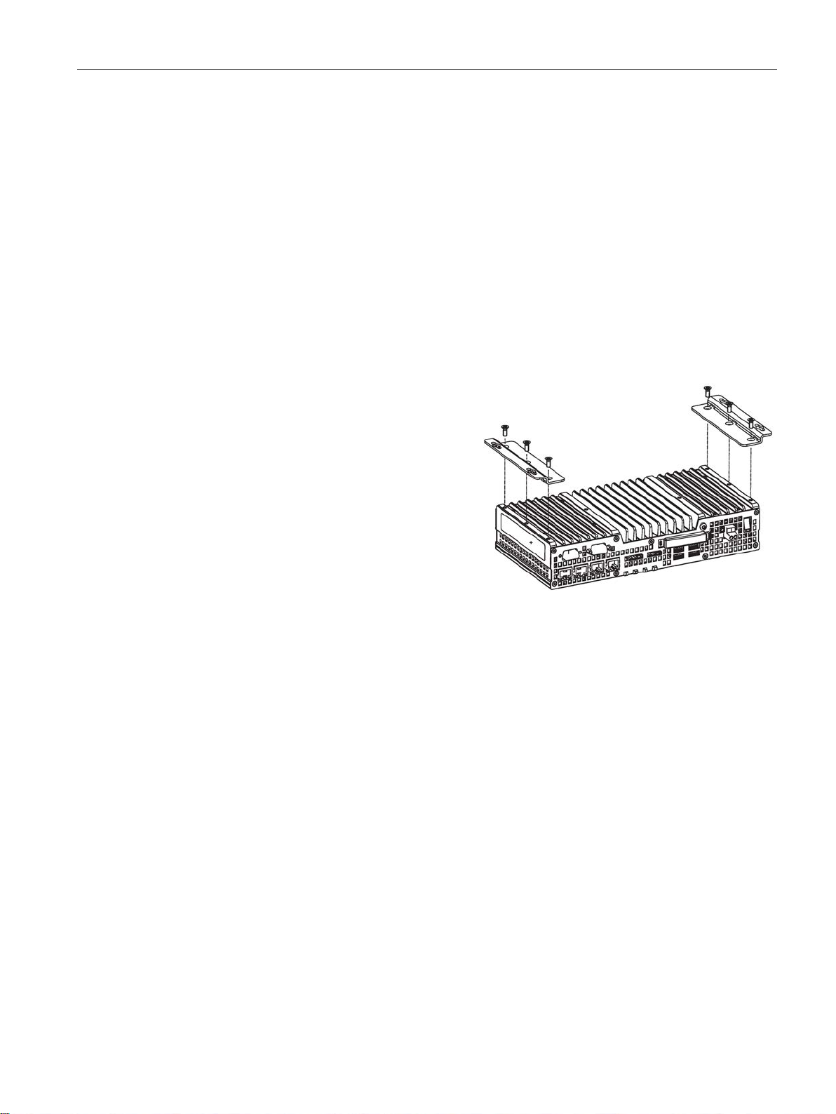
1. Secure each mounting bracket with 3
screws.
3.2 Installing the device
The fasteners and screws required are supplied with the device for the selected mounting
option (as specified in order number).
● 2 mounting brackets
● 6 screws
● 1 T20 screwdriver
SIMATIC IPC427E
Operating Instructions, 09/2017, A5E37454814-AB
33
Page 34

Installing and connecting the device
3.2.4
Upright mounting
Requirement
Procedure
1. Secure each mounting bracket with three
screws.
3.3 Connecting the device
The fasteners and screws required are supplied with the device for the selected mounting
option (as specified in order number).
● 2 mounting brackets
● 6 screws
● 1 T20 screwdriver
SIMATIC IPC427E
34 Operating Instructions, 09/2017, A5E37454814-AB
Page 35

Installing and connecting the device
3.3
Connecting the device
3.3.1
Notes on connecting
WARNING
Risk of fire and electric shock
WARNING
Risk of lightning strikes
NOTICE
Fault caused by I/O devices
3.3 Connecting the device
The on/off switch does not isolate the device from the power supply. Risk of electric shock if
the device is opened incorrectly or defective. There is also a risk of fire if the device or
connecting lines are damaged.
You should therefore protect the device as follows:
• Always pull out the power plug when you are not using the device or if the device is
defective. The power plug must be freely accessible.
• Connect the device to a protective conductor as instructed, see section "Connecting the
protective conductor".
• Use a central isolating switch in the case of cabinet installation.
A lightning flash may enter the mains cables and data transmission cables and jump to a
person.
Death, serious injury and burns can be caused by lightning.
Take the following precautions:
• Disconnect the device from the power supply in good time when a thunderstorm is
approaching.
• Do not touch mains cables and data transmission cables during a thunderstorm.
• Keep a sufficient distance from electric cables, distributors, systems, etc.
The connection of I/O devices can cause faults in the device.
The result may be personal injury and damage to the machine or plant.
Note the following when connecting I/O devices:
• Read the documentation of the I/O devices. Follow all instructions in the documentation.
• Only connect I/O devices which are approved for industrial applications in accordance
with EN 61000-6-2 and IEC 61000-6-2.
• I/O devices that are not hotplug-capable may only be connected after the device has
been disconnected from the power supply.
SIMATIC IPC427E
Operating Instructions, 09/2017, A5E37454814-AB
35
Page 36

Installing and connecting the device
NOTICE
Damage through regenerative feedback
3.3 Connecting the device
Regenerative feedback of voltage to ground by a connected or installed component can
damage the device.
Connected or built-in I/Os, for example, a USB drive, are not permitted to supply any
voltage to the device. Regenerative feedback is generally not permitted.
SIMATIC IPC427E
36 Operating Instructions, 09/2017, A5E37454814-AB
Page 37
Installing and connecting the device
3.3.2
Connecting the protective conductor
WARNING
Electrical shock hazard and risk of fire
Requirement
Procedure
1. Crimp the cable lug onto the protective conductor.
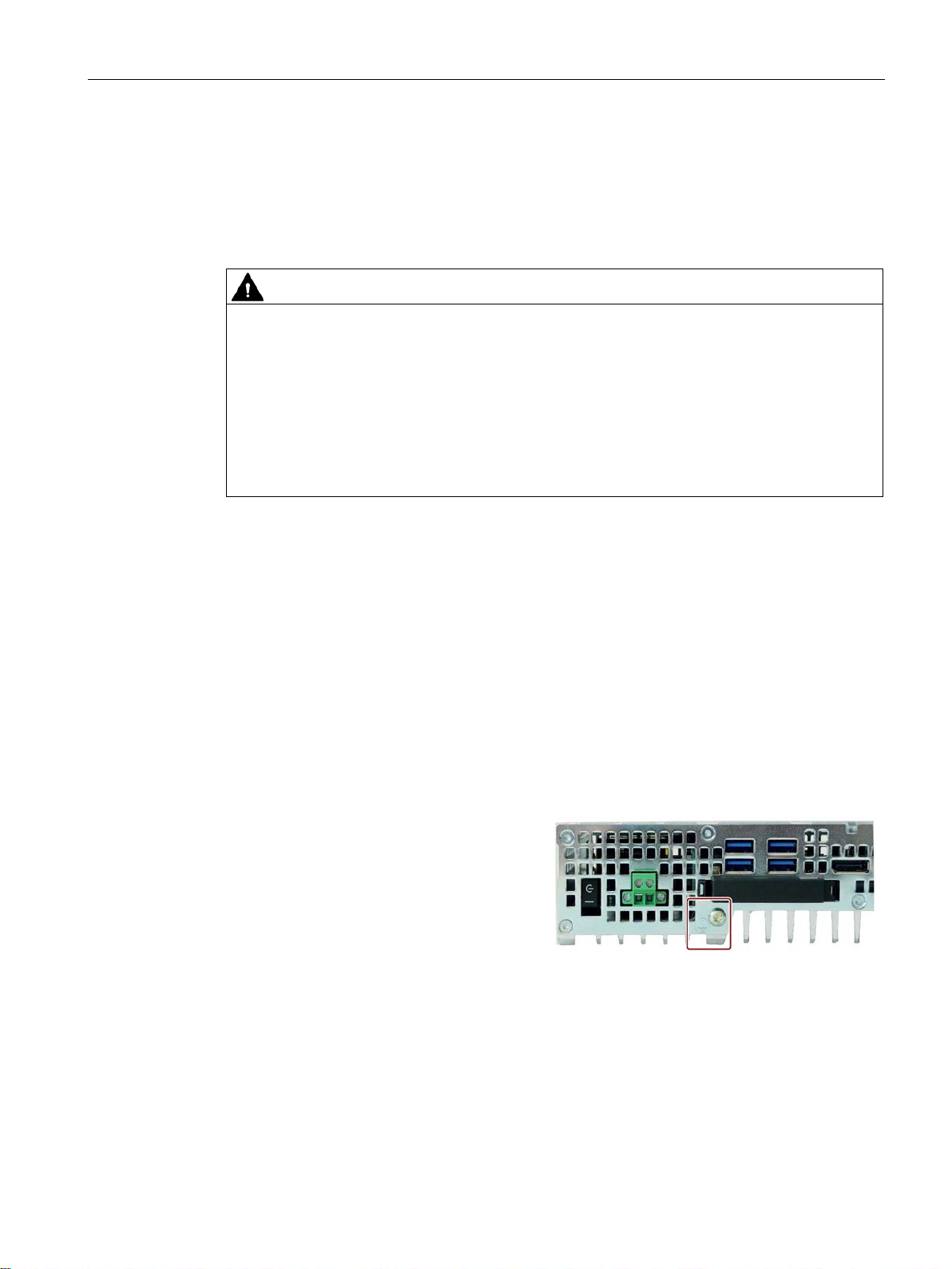
2. Screw the cable lug onto the protective
conductor connection as shown.
3. Wire the protective conductor to the protective conductor connection of
net in which the device is installed.
3.3 Connecting the device
The protective conductor connection is needed to protect the device. The protective
conductor discharges dangerous currents, triggering a surge protection switch. The
protective conductor also improves the discharge of interference generated by external
power cables, signal cables or cables for I/O devices to ground.
Internal components of a faulty device may carry dangerous voltages that pose the risk of
fire or electrical shock. Risk of death and serious injury.
• Always connect the ground conductor before you commission the device.
• The protective conductor connection on the device must be connected to the protective
conductor of the control cabinet or system in which the device is installed.
• Never operate the device without protective conductor.
• Take a faulty device out of service immediately and mark it accordingly.
● The device has been installed.
● 1 protective conductor, minimum cross section 2.5 mm
● 1 T20 screwdriver
● 1 x M4 cable lug
2
the control cabi-
SIMATIC IPC427E
Operating Instructions, 09/2017, A5E37454814-AB
37
Page 38

Installing and connecting the device
3.3.3
Connecting peripheral equipment
Note
Observe suitability for industrial applications
Only connect I/O devices that are suitable for industrial applications in accordance with
EN
Note
I/O devices capable of hot-plugging (USB)
Hot
NOTICE
Non-hot-plug I/O devices
Note
Wait at least ten seconds before you reinsert USB devices.
Note that the EMC immunity of standard USB devices is designed only for office
environments.
tasks. Only industrial grade USB devices are permitted for use in industrial environments.
The USB devices are developed and marketed by the respective supplier. The respective
produc
shall apply.
Note
A monitor should be connected and switched on before device booting to ensure it is
correctly detected and run by the BIOS and the operating system. The screen may otherwise
remain dark.
Note
The connected or built
A counter e.m.f. greater than 0.5 V to ground on the + 3.3 V DC / + 5 V DC / + 12 V DC due
to a connected or
computer.
When measuring the counter emf, remember the following:
•
•
•
3.3 Connecting the device
IEC 61000-6-2.
-plug I/O devices (USB) may be connected while the PC is in operation.
I/O devices that do not support hot-plugging may not be connected until the device is
powered off. Strictly adhere to the specifications in the I/O manuals.
These USB devices are appropriate for handling commissioning and service
t supplier provides support for the USB devices. The manufacturer's terms of liability
-in I/Os should not introduce a counter emf into the device.
integrated component can prevent normal operation or even destroy the
The computer in question must be turned off.
During the measurement, all cables from the plant to the computer should be connected.
All other components in the plant must be active.
SIMATIC IPC427E
38 Operating Instructions, 09/2017, A5E37454814-AB
Page 39

Installing and connecting the device
3.3.4
Connecting expansion cards
Requirement
Procedure
1. Open the cover by pushing the indicated
latching hooks in the direction of the a
row. Open the cover in the direction of
the
cess the expansion card interfaces.
2. Connect the cable to one of the indicated
slots.
3. Attach the cover
close it. Make sure that the latching
hooks snap into place so that the cover is
secured.
See also
3.3 Connecting the device
This section applies to devices with expansion cards.
The expansion card interface is protected by a cover. There are two holes in the cover for
wiring.
● The device is switched off.
In this example, the expansion card is a USB expansion card.
r-
arrow and lift it off. You can now ac-
Dimension drawing - device with expansion cards (Page 104)
SIMATIC IPC427E
Operating Instructions, 09/2017, A5E37454814-AB
at the points shown and
39
Page 40

Installing and connecting the device
3.3.5
Connecting the terminal
Requirements
Procedure
NOTICE
Damage to the device
Note
Make sure that the cores are connected to the correct terminals. Observe the labeling for the
contacts on the front cover of the device.
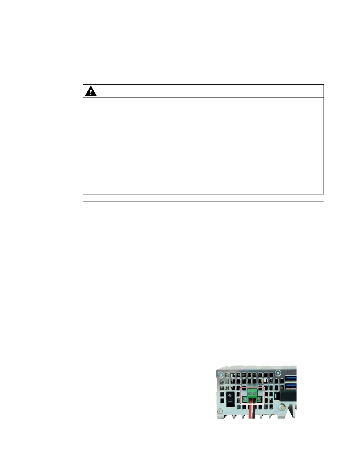
1. Connect the lines as shown. Make
sure the connection terminal is in the
correct position as shown.
3.3 Connecting the device
The connection terminal for connecting the power supply is fitted to the device. The
connection terminal is designed for cores with a cross-section of between 0.25 mm² and
2.5 mm². Only connect cores with a cross-section of ≥ 0.5 mm².
You can use either semi-rigid or flexible cables. You do not need to use end sleeves.
● 1 connection terminal
● 1 0.5 x 3 Philips screwdriver
Do not adjust the screws in the connection terminal when it is plugged into the device. The
pressure of the screwdriver on the connection terminal and the socket can damage the
device.
Connect the wires to the connection terminal when it is not plugged in.
SIMATIC IPC427E
40 Operating Instructions, 09/2017, A5E37454814-AB
Page 41
Installing and connecting the device
3.3.6
Connecting the power supply
WARNING
Risk of fire and electric shock
Note
The device should only be connected to a 24 V
requirements of safe extra low voltage
The power supply must meet the requirement NEC Class 2 or LPS according to the
IEC/EN/DINEN/UL 60950
Requirement
Procedure
1. Insert the terminal at the marked
position.
2. Secure the terminal using the int
grated screws.
3.3 Connecting the device
Please note the following to ensure you operate the device safely and in accordance with
regulations:
The on/off switch does not isolate the device from the power supply. Risk of electric shock if
the device is opened incorrectly or defective. There is also a risk of fire if the device or
connecting cables are damaged.
Death or serious bodily injury can result.
You should therefore protect yourself and the device as follows:
• Always pull out the power plug when you are not using the device or if the device is
defective. The power plug must be freely accessible.
• Connect the device to a protective conductor as instructed (see section "Connecting the
protective conductor").
• Use a central isolating switch for cabinet installation.
DC power supply which meets the
(SELV) according to IEC/EN/DIN EN/UL 60950-1.
-1.
The device has reverse polarity protection.
● The device has been installed.
● The protective conductor is connected.
● 1 wired terminal.
The corresponding 24 V DC power supply is off.
● 1 0.5 × 3 Philips screwdriver
e-
SIMATIC IPC427E
Operating Instructions, 09/2017, A5E37454814-AB
41
Page 42

Installing and connecting the device
3.3.7
Connecting the device to networks
Ethernet
Note
To use the Windows reboot with the SIMATIC CPU1507S (F) Software
SIMATIC IPC427E, assign the Ethernet interfaces X2 or X3 to the PC station in STEP 7.
Industrial Ethernet
T
Note
You need a category 6 Ethernet cable for operation at 1000
PROFINET
SIMATIC NET
Additional information
3.3 Connecting the device
The options for integrating the device into existing or planned system environments and
networks are as follows:
The integrated Ethernet interfaces can be used for communication and for data exchange
with automation devices such as SIMATIC S7.
For this, you need TIA Portal, STEP 7, WinCC, WinCC flexible, WinAC and SIMATIC NET.
Controller on the
You can establish a network between the device and other PCs via Industrial Ethernet. The
on-board LAN interfaces are (
rates of 10/100/1000 Mbps.
PROFINET can be operated via:
● Standard Ethernet interfaces (RT)
Use this software package to create, operate and configure an innovative network for Field &
Control level. Information on this can be found on the SIMATIC NET Manual Collection CD.
The software package and the documentation are not included in the product package.
You will find additional information in the catalog and on the Internet at Industry Mall, the
ordering system for automation and drive technology (https://mall.industry.siemens.com).
wisted-Pair) TP interfaces that support data transmission
Mbps.
SIMATIC IPC427E
42 Operating Instructions, 09/2017, A5E37454814-AB
Page 43

Installing and connecting the device
3.3.8
Installing the strain relief
Requirement
Procedure
Installation
1. Removed the indicate
screws and fasten the strain relief at the
indicated points.
Use the oval head screws included with
the strain relief.
Removal
3.3 Connecting the device
Strain relief for the device is provided in the scope of delivery.
● 1 strain relief
● 2 screws
● 1 T10 screwdriver
d countersunk
Follow the steps for installation in reverse order.
SIMATIC IPC427E
Operating Instructions, 09/2017, A5E37454814-AB
43
Page 44

Installing and connecting the device
3.3.9
Securing the lines
Requirement
Procedure
1. Pass the cable tie around the strain relief
bar and secure the cables as shown.
2. Cut off the protruding ends of the cable
ties.
3.3 Connecting the device
Secure each line connected to the device to the strain relief using a cable tie. The cable ties
required are not included.
● Up to 6 cable ties for USB, Ethernet
Cable tie width 3 mm max.
● 1 cutting tool
SIMATIC IPC427E
44 Operating Instructions, 09/2017, A5E37454814-AB
Page 45

4
4.1
General information on commissioning
CAUTION
Danger of burns
Note
Windows 10 - Read the UWF information
The configurable write filter (Unified Write Filter) is available with Windows 10.
Read the UWF information if you activate and use it, otherwise you may
loss.
Note
Windows Embedded Standard 7
Read the EWF and FBWF information
Two configurable write filters (Enhanced Write Filter and File Based Write Filter) are
provided with Windows
activate and use them, otherwise you may experience data loss.
•
•
Note
Configuring memory cards in the device
Memory cards used in a device need to be configured on that device. Memory cards
configured on other devices will not boot as the drive
The surface of the device can reach temperatures of over 70 °C. Any unprotected contact
may cause burns.
Avoid direct contact during operation of the device. Touch the device only with appropriate
protective gloves.
experience data
Embedded Standard. Read the EWF/FBWF information if you
Enhanced Write Filter (EWF) (Page 53)
File Based Write Filter (FBWF) (Page 56)
parameters will be different.
SIMATIC IPC427E
Operating Instructions, 09/2017, A5E37454814-AB
45
Page 46

Commissioning the device
Requirement
4.1 General information on commissioning
● The device is connected to the power supply.
● The protective conductor is connected.
● The connection cables are plugged in correctly.
● The following hardware is available for initial commissioning:
– One USB keyboard
– One USB mouse
– A monitor/display
SIMATIC IPC427E
46 Operating Instructions, 09/2017, A5E37454814-AB
Page 47

Commissioning the device
4.2
Initial commissioning
NOTICE
Faulty installation
Procedure
Note
Once the
4.2 Initial commissioning
If the device was ordered and delivered with operating system, the operating system preinstalled on the drive is set up automatically after the initial switch-on.
If you change the default values in the BIOS Setup or if you turn off the device during
installation, you disrupt the installation and the operating system is not installed correctly.
The operating safety of the device and the plant is at risk.
Do not switch off the device during the entire installation process. Do not change the default
values in the BIOS Setup.
1. Set the on/off switch to the "ON" position.
The "PC ON/WD" LED flashes alternately green and yellow to indicate the progress of the
BIOS self-test during device booting. After the completion of the BIOS self-test, the "PC
ON/WD" LED is continuously lit green.
During the self-test, the following message appears:
Press Esc for Boot Options
2. Wait for the message to disappear.
3. Follow the instructions on the screen.
The following steps are required only when switching on the device for the first time after
delivery:
4. Make the region and language settings.
If you want your system language to be international, select English. Information about
changing the region and language settings is available in the section "Servicing and
maintaining the device", under "Installing software".
operating system has been set up, the device may restart.
5. Type in the product key as required.
The product key is located below the identification data of the device on the "Certificate of
Authentication" COA label, in the "Product Key" line.
SIMATIC IPC427E
Operating Instructions, 09/2017, A5E37454814-AB
6. If the device is connected with a SIMATIC Industrial Flat Panel, the setup of the
SIMATIC IPC Panel Drivers and Tools software is started automatically after operating
system installation (see next section).
The installation of the operating system is complete.
47
Page 48

Commissioning the device
4.3
Windows Action Center
Functions
Firewall
Antivirus software
Automatic updates
User Account Control:
4.4
IPC Driver and Tools
Panel description - Panel Drivers and Tools software
4.3 Windows Action Center
The Action Center checks the status of the device with regard to the important safety
aspects listed below. If a problem is found, the Action Center provides recommendations on
how you can better protect the device.
●
Internet access to the device by unauthorized users. The firewall is enabled in the
delivery state.
: The Windows Firewall adds protection to the device by blocking network or
●
eliminating viruses and other security threats. No antivirus software is installed in the
delivery state.
●
search for the latest critical updates for the device and to install them automatically.
You can enable or disable this option for Windows 7 and Windows 10 during
commissioning of Windows.
●
modify important Windows settings. You can then either acknowledge this warning or
prevent the program from changing the Windows settings.
This option is enabled in the delivery state for Windows 7 and Windows 10.
: Antivirus programs add protection to the device by searching for and
: Using the Automatic Update feature allows Windows to regularly
User Account Control issues a warning when programs attempt to
The SIMATIC IPC PDT software installs the "IPC Configuration Center" and, optionally, the
"IFP Ethernet Monitor" software.
The existing hardware components are automatically detected by the associated software.
The most important features of the software are:
● Dialog-guided installation
● Configuration via the IPC Configuration Center of:
– Brightness
– Screen saver
– Tools
– Touch settings
– Ethernet Monitor settings
All other functions are described in the IPC Panel Driver and Tools operating manual.
SIMATIC IPC427E
48 Operating Instructions, 09/2017, A5E37454814-AB
Page 49

5
5.1
Monitoring Functions
5.1.1
Overview of the monitoring functions
SIMATIC IPC DiagBase software
Note
For more information on SIMATIC IPC DiagBase software functionality, please refer to the
relevant Online Help.
SIMATIC IPC DiagMonitor software
The basic version of the device also provides monitoring functions. The following display,
monitoring and control functions are available when the appropriate software is used:
● Temperature monitoring (over-/undertemperature)
● Battery monitoring: The state of the lithium battery is monitored.
● Monitoring of hard disks, memory cards and SSD drives with S.M.A.R.T. functionality
● Watchdog: Hardware or software reset of the computer
● Operating hours counter (information on the cumulative run time)
● Hard disk status
With the SIMATIC IPC DiagBase software included in the scope of delivery, use these
functions for local monitoring. Use the "DiagBase Management Explorer" application to
obtain a clear overview of the controls. Use the DiagBase Alarm Manager to receive
notifications about individual alarms.
The SIMATIC IPC DiagMonitor software can be ordered as an accessory (not included in the
scope of delivery). The CD contains both the monitoring software and the software for the
stations to be monitored. The interface specifications and a library for creating your own
applications are also provided.
SIMATIC IPC427E
Operating Instructions, 09/2017, A5E37454814-AB
49
Page 50

Extended device functions
5.1.2
Temperature monitoring/display
Reaction
Option
Alarm window of the DiagBase or DiagMonitor software alerts the user.
None
5.1 Monitoring Functions
The temperature is recorded by means of three temperature sensors. The sensors monitor
the processor temperature and the temperature in the area of the RAM module and the
motherboard at the display port sockets.
The following fault reaction is triggered if one of the three temperature values exceeds the
set thermal threshold:
The temperature error is saved until the temperatures have fallen below the thresholds and it
is reset by one of the following measures:
● Acknowledgment of the error message by the user with DiagBase or DiagMonitor
software
● Restart of the device
SIMATIC IPC427E
50 Operating Instructions, 09/2017, A5E37454814-AB
Page 51

Extended device functions
5.1.3
Watchdog (WD)
Configuration
Function
Watchdog reactions
Option
Reaction
Reset on
Executes a hardware reset when the watchdog expires
Restart
Restarts the operating system when the watchdog expires
NOTICE
"Reset on" option
Watchdog monitoring times
Note
When you change the
5.1 Monitoring Functions
You configure the watchdog with the DiagBase or DiagMonitor software.
The watchdog is able to monitor system runtime and informs the user about the different
reactions that are triggered if the system does not respond to the watchdog within the
specified monitoring time.
A watchdog alarm is retained after a restart and is only reset and logged by the DiagBase or
DiagMonitor software. The watchdog configuration is retained in the process.
The following reactions can occur if the watchdog is not addressed within the set time:
Reset off Executes no action when the watchdog expires
Shutdown Shuts down the operating system when the watchdog expires
The "Reset on" option immediately triggers a hardware reset that may result in loss of data
under Windows and damage to the installation.
The monitoring time can be configured with the DiagBase or DiagMonitor software.
monitoring time, the change becomes effective immediately.
SIMATIC IPC427E
Operating Instructions, 09/2017, A5E37454814-AB
51
Page 52

Extended device functions
5.1.4
Battery monitoring
5.1.5
Mass storage monitoring
5.2
Unified Write Filter (UWF)
Note
UWF is disabled in the delivery state.
Note that memory is reduced when UWF is enabled.
NOTICE
Risk of data loss with enabled UWF
See also
5.2 Unified Write Filter (UWF)
The installed backup battery has a service life of 5 years. The status can be checked with
two-tier battery monitoring. The information can be read via an I/O register and evaluated by
the DiagBase or DiagMonitor software.
When the first warning threshold is reached, the remaining service life of the battery for
buffering time and CMOS data is at least 1 month.
The state of HDD, SSD and CFast cards is monitored via SMART bit and reported by
DiagBase or DiagMonitor.
The Unified Write Filter is a configurable write filter that makes it possible to assign writeprotection to data storage media, such as hard disks, CFast cards, SSDs, internal USB
drives, or external SATA drives.
External removable data storage media such as USB sticks and other flash drives, which are
recognized by the operating system as a removable data storage medium, are not
supported.
UWF combines the advantages of older write filters such as EWF and FBWF. It prevents all
write access to protected media and transfers the data to buffer memory (overlay). This
increases the reliability and stability of the system as well as the service life of write-sensitive
media such as SSDs and CFast cards.
When UWF is enabled, all changes made to storage media with a UWF write protection
after booting can be lost when the device is shut down. Proceed as follows to prevent this
situation:
• Make changes to storage media only when UWF is disabled.
SIMATIC IPC Windows 10 User Manual
(https://support.industry.siemens.com/cs/ww/de/view/109749498/en?dl=en)
SIMATIC IPC427E
52 Operating Instructions, 09/2017, A5E37454814-AB
Page 53

Extended device functions
5.3
Enhanced Write Filter (EWF)
Purpose and function
CAUTION
Data loss with several write filters
Note
Windows Embedded Standard
The Enhanced Write Filter is deactivated in the Windows Embedded Standard default state.
•
•
5.3 Enhanced Write Filter (EWF)
The Enhanced Write Filter (EWF) is a function that is only available for Windows Embedded
operating systems. EWF is a write filter that can be configured by the user.
You can use the Enhanced Write Filter to boot Windows Embedded Standard from read-only
media, for example, memory cards or Solid State Drives (SSD), or provide individual
partitions with write protection.
EWF can be used to minimize write access to storage media. This is important because the
write cycles are limited due to technical reasons. We therefore recommend using EWF if you
work with these storage media.
If you use HORM or compressed NTFS, EWF is indispensable.
Both EWF and FBWF are preinstalled in the SIMATIC IPC images. If several writer filters
are active on one partition at the same time, you may experience data loss. This may
damage the machine or plant.
Make sure that you only activate one write filter for each partition.
Back up your data after installation of the operating system and programs.
Activate the EWF.
SIMATIC IPC427E
Operating Instructions, 09/2017, A5E37454814-AB
53
Page 54

Extended device functions
Setting EWF
Function
Command
Write-protect drive C: Power on
ewfmgr c: -enable
Modified data on drive C: apply
ewfmgr c: -commit
Display information about the EWF drive
ewfmgr c:
Display help
ewfmgr /h
Note
The EWF commands affecting the write protection do not become active until after the next
booting process.
Note
The EWF command ewfmgr c:
commitanddisable
live
5.3 Enhanced Write Filter (EWF)
The following programs can be used to install, enable or disable the EWF:
● EWFMGR.EXE
● SIMATIC IPC EWF Manager.
The SIMATIC IPC EWF Manager is preinstalled and included on the supplied USB stick
(DocuAndDrivers\Drivers).
Start the SIMATIC IPC EWF Manager as follows:
● "Start > All Programs >Siemens Automation > SIMATIC > EWF Manager > EWF
Manager"
Configure the SIMATIC IPC EWF Manager as follows:
● "Start > All Programs > Siemens Automation > SIMATIC > EWF Manager > EWF
Settings"
or
● Click the "SIMATIC IPC EWF Manager" icon in the system tray.
The following functions are available:
Write-protect drive C: disable: the modified data are
applied
ewfmgr c: -commitanddisable
-
may not be used with the option -
.
SIMATIC IPC427E
54 Operating Instructions, 09/2017, A5E37454814-AB
Page 55

Extended device functions
Special notes for use
ewfmgr c: -commit
Note
When the system is set to automatically adjust the clock for daylight saving
systems without central time management and with activated EWF set the clock forward or
backward by one hour in the daylight saving time or standard time period each time the
system boots.
The reason for this behavior is that Windows
that the changeover to daylight saving time has occurred. Since this file is also protected
against modification by the EWF, the marker is lost during the boot sequence and the
adjustment is made again.
We therefore re
clock manually.
Follow these steps:
1.
2.
ewfmgr c: -commit
5.3 Enhanced Write Filter (EWF)
If EWF is enabled, when the PC shuts down all changes made on drive C: after the boot
process are lost.
These changes are only retained on the PC in the following cases:
● EWF is disabled when you make changes.
● EWF is enabled and you save the changes before shutting down the device using the
following command on C: drive :
time adjustment,
Embedded Standard 7 makes a registry entry
commend that you deactivate the automatic adjustment and change the
Deactivate automatic adjustment in the Control Panel: In the "Time Zone" tab opened
with the menu command "Start > Control Panel > Date and Time", remove the check
mark from the "Automatically adjust clock for daylight saving changes" check box.
Save the change you have made with
and then reboot the system.
SIMATIC IPC427E
Operating Instructions, 09/2017, A5E37454814-AB
55
Page 56

Extended device functions
5.4
File Based Write Filter (FBWF)
Purpose and function
Comparison between EWF and FBWF
CAUTION
Data loss with several write filters
5.4 File Based Write Filter (FBWF)
With the Embedded Standard 7, Microsoft introduced a second write filter, the File Based
Write Filter (FBWF).
In contrast to EWF, which protects partitions based on sectors, FBWF works on the file level.
When FBWF is enabled, all files and folders of a partition are protected unless they are
included in an exception list.
FBWF is disabled by factory default in the operating system images for SIMATIC IPC and
must be enabled and configured by the user.
When you enable FBWF, the folders C:\FBWF and D:\FBWF are authorized for writing by
default.
● You should prefer FBWF, because it is more flexible in its configuration and allows
immediate writing without rebooting.
● If you use HORM or compressed NTFS, EWF is indispensable.
Both EWF and FBWF are preinstalled in the SIMATIC IPC images. If several writer
filters are active on one partition at the same time, you may experience data loss. This
may damage the machine or plant.
Make sure that you only activate one write filter for each partition.
SIMATIC IPC427E
56 Operating Instructions, 09/2017, A5E37454814-AB
Page 57

Extended device functions
Configuring FBWF
Note
•
space
•
•
Function
Command
Display the current FBWF status
fbwfmgr /displayconfig
Enable FBWF after the next startup
fbwfmgr /enable
Write to protected files
fbwfmgr /commit c: \Test.txt
Adding/removing elements in the exception list:
fbwfmgr /addexclusion C: \Test.txt
fbwfmgr /addexclusion C: \Test folder
fbwfmgr /removeexclusion
C: \Test.txt
fbwfmgr /removeexclusion C: \Test
folder
Call up the help function
fbwfmgr /?
5.4 File Based Write Filter (FBWF)
FBWF can be configured in command console using the program FBWFMGR.EXE.
Observe the following syntax: Enter a
Changes for direct write access only take effect after rebooting.
Only existing files and folders can be entered in the exception list.
• Add file
after the drive designation colon.
• Add folder
• Remove file
• Remove folder
Detailed instructions on FBWF are available on the Internet (http://msdn.microsoft.com/en-
us/library/aa940926(WinEmbedded.5).aspx).
SIMATIC IPC427E
Operating Instructions, 09/2017, A5E37454814-AB
57
Page 58

Extended device functions
5.5
Buffer memory NVRAM
5.6
Operation without monitor and keyboard
5.7
Active Management Technology (AMT)
5.5 Buffer memory NVRAM
Depending on the configuration ordered, the motherboard is equipped with an NVRAM that
applications can use to back up data in the event of a power failure.
Failure of the supply voltage for a duration longer than 5 ms is indicated by the DC FAIL
signal.
Depending on the system utilization, up to 512 KB can be saved in the NVRAM.
A memory window with a maximum size of 512 KB can be displayed by means of PCI
address register. The base address is initialized by the BIOS.
A corresponding function is implemented there for using the NVRAM under WinAC RTX and
for using the CPU150xS SW controller.
The device can be operated without a monitor and keyboard. The device startup is
guaranteed without these peripherals. A USB keyboard and mouse and a monitor can be
connected later for diagnostics.
A digital DVI monitor or DisplayPort monitor cannot be activated retrospectively unless the
Windows Embedded Standard or Windows 7 or Windows 10 Ultimate operating system has
completed booting.
AMT (Active Management Technology) is technology for the remote maintenance of
computers (simply called AMT-PC in the remainder of the document) and it includes the
following functions:
● Keyboard Video Mouse( KVM) Redirection: Using KVM that is integrated in the AMT
hardware you access the AMT PC remotely. With KVM, you can also control AMT PCs
that have no operating system or a defective operating system. A KVM remote session is
always possible with the KVM server integrated in the firmware. This means you can
restart the PC and change the BIOS setup remotely.
● Remote power management: AMT PCs can be turned on and off and restarted from
another PC.
● SOL (Serial over LAN): Redirection of the data of a serial interface to the network. The
main use of the function is text-based remote control of an AMT PC using a console.
● IDE redirection: An ISO file on the help desk PC can be mounted on the AMT PC and
used as a DVD drive.
An ISO file contains a memory image of the content of a CD or DVD structured in the
ISO 9660 format.
● Remote reboot: An AMT PC can be booted from a bootable ISO file made available by
another PC.
SIMATIC IPC427E
58 Operating Instructions, 09/2017, A5E37454814-AB
Page 59

Extended device functions
SIMATIC IPC Remote Manager
Requirement
Configuration of the AMT PC
5.7 Active Management Technology (AMT)
The "SIMATIC IPC Remote Manager" software is available for utilization of the AMT
functions with SIMATIC IPCs. The software can be ordered from the Siemens online
ordering system. For detailed information about "SIMATIC IPC Remote Manager", refer to
the corresponding product documentation: SIMATIC IPC Remote Manager
(http://support.automation.siemens.com/WW/view/en/48707158)
Typical areas of application and functions of the SIMATIC IPC Remote Manager:
● Remote maintenance of SIMATIC IPC with AMT, for example for service purposes in the
case of a defective operating system or for adapting BIOS settings.
● Diagnostics without on-site use
● Convenient service: Access to AMT clients, such as headless systems, without additional
hardware
● Resource management
● A device with Xeon or Core i5 processor
● A functioning and configured management engine
● A functioning and configured Ethernet connection
● A help desk PC with a functioning and configured Ethernet connection for the full AMT
functionality
You configure AMT by means of the BIOS setup and MEBx (Management Engine BIOS
Extension). MEBx is a BIOS extension for configuration of AMT (see BIOS description in
section "Technical specifications").
SIMATIC IPC427E
Operating Instructions, 09/2017, A5E37454814-AB
59
Page 60

Extended device functions
5.8
Trusted Platform Modul (TPM)
NOTICE
Import restrictions
Activating the Trusted Platform Module
Using the Trusted Platform Module
Note
Risk of data loss
If you lose the password for the drive encryption, you will not be able to restore the data. You
will then lose accesss to the encrypted drive.
The warranty does not cover a reset of the hardware in the event of a loss
Please store the password carefully and make sure it is protected against unauthorized
access.
5.8 Trusted Platform Modul (TPM)
Depending on the ordered configuration, the motherboard contains a Trusted Platform
Module (TPM). A TPM is a chip that adds important security functions to your device, such
as enhanced protection of the PC against unauthorized manipulation by third parties. The
current operating systems, for example, Windows 7 or Windows 10, support these security
functions.
TPM technology is subject to legal restrictions in some regions and may not be used there.
You could commit a crime by importing or exporting the device in certain countries.
Note the respective import provisions for the TPM module.
The TPM can be activated under "Security" in the BIOS setup. Please follow the instructions
in the BIOS setup.
The TPM can be used in Windows with the "BitLocker" drive encrypter.
The Windows operating system is installed in UEFI mode in the delivery state for this
purpose. It is not possible to use BitLocker under Window Embedded operating systems as
these are installed in MBR mode.
To use BitLocker, follow the relevant instructions in the operating system.
of a password.
SIMATIC IPC427E
60 Operating Instructions, 09/2017, A5E37454814-AB
Page 61

6
6.1
Installing and removing the memory module
6.1.1
Opening the device
Note
Work on the open device may only be carried out by authorized and qualified personnel.
Within the warranty period,
cards.
NOTICE
The device contains electronic components that may be destroyed by ESD
Requirement
you may only expand the hardware with memory and expansion
You therefore need to take precautionary measures before you open the device. Please
refer to the ESD Directives on handling electrostatic-sensitive components in ESD guideline
(Page 98).
● The device is disconnected from the power supply.
● 1 T10 screwdriver
SIMATIC IPC427E
Operating Instructions, 09/2017, A5E37454814-AB
61
Page 62

Expanding and assigning parameters to the device
Procedure
Opening the device
1. Remove the marked screws.
2. Remove the two
and loosen the two outer screws slightly.
3. Re
4. Lift off the front cover by about 2 to 3
5.
Remove the backup battery from its
gu
Obser
(Page 76)".
6.
Put down the front panel.
Closing the device
6.1 Installing and removing the memory module
indicated central screws
move the marked screws.
ide in the front panel.
ve the information in section "Installing and removing the backup battery
Proceed in reverse order.
cm.
SIMATIC IPC427E
62 Operating Instructions, 09/2017, A5E37454814-AB
Page 63

Expanding and assigning parameters to the device
6.1.2
Opening the device containing expansion cards
Note
Work on the open device may
Within the warranty period, you may only expand the hardware with memory and expansion
cards.
NOTICE
The device contains electronic components that may be destroyed by ESD
Requirement
Procedure
Opening the device
1.
Remove the marked screws.
2.
Lift off the front panel in the direction of
the arrow
3.
Put down the front panel.
Closing the device
6.1 Installing and removing the memory module
only be carried out by authorized and qualified personnel.
You therefore need to take precautionary measures before you open the device. Please
refer to the ESD Directives on handling electrostatic-sensitive components in ESD guideline
(Page 98).
● The device is disconnected from the power supply.
● 1 T10 screwdriver
Proceed in reverse order.
SIMATIC IPC427E
Operating Instructions, 09/2017, A5E37454814-AB
63
Page 64

Expanding and assigning parameters to the device
6.1.3
Replacing memory modules
Note
Use only the memory
Requirement
Procedure
Note
Observe the directives on handling electrostatic
(Page
Removal
1. Push down the module clips towards the
outside.
The memory module tilts forward.
2. Remove the memory module from the
slot.
6.1 Installing and removing the memory module
The motherboard is equipped with one slot for an SO-DIMM DDR4 memory module. You
can use it to expand the memory capacity of the device to a maximum of 16 GB.
modules recommended by Siemens AG.
● The device is disconnected from the power supply.
● The device is open (see sections "Opening the device (Page 61)" and "Opening the
device containing expansion cards (Page 63)").
-sensitive components in ESD guideline
98).
SIMATIC IPC427E
64 Operating Instructions, 09/2017, A5E37454814-AB
Page 65
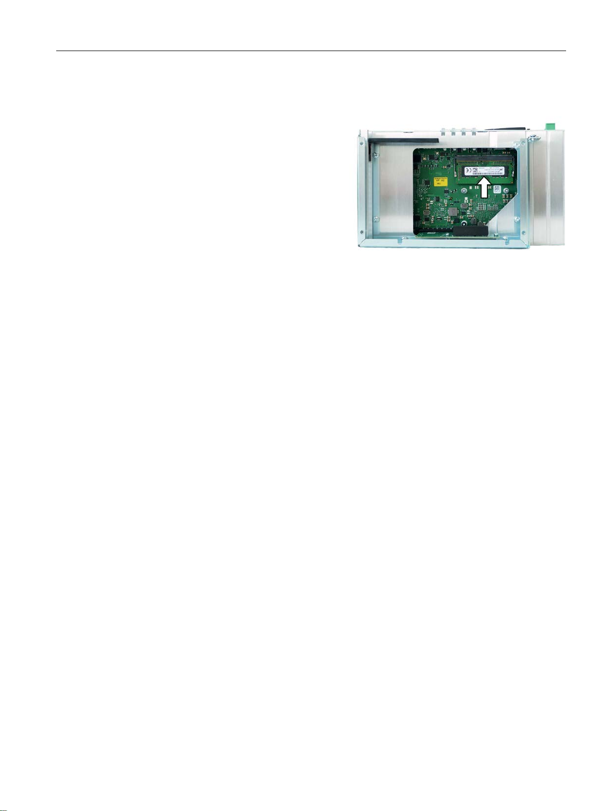
Expanding and assigning parameters to the device
Installation
1. Insert the
marked slot at an incline with the contact
side facing the motherboard.
2. Carefully press the memory module into
the contact strip until the latches engage.
After insertion and removal
6.1 Installing and removing the memory module
memory module into the
The new memory configuration is detected automatically. The memory configuration is
displayed in the main BIOS Setup menu under "Total Memory".
Close the device.
The new memory capacity will be automatically detected and displayed in the BIOS setup
when the device is switched on.
SIMATIC IPC427E
Operating Instructions, 09/2017, A5E37454814-AB
65
Page 66

Expanding and assigning parameters to the device
6.2
Installing and removing CFast cards
NOTICE
Damage to the device
Requirement
6.2 Installing and removing CFast cards
The device has a slot for a CFast card on the side with the interfaces. Always use SIMATIC
IPC CFast cards for industrial applications.
The CFast and CompactFlash connections are not compatible.
Use the slot described here only for a CFast card; otherwise, the device will be damaged.
● The device is switched off.
● SIMATIC IPC CFast card that is approved for industrial applications.
SIMATIC IPC427E
66 Operating Instructions, 09/2017, A5E37454814-AB
Page 67

Expanding and assigning parameters to the device
Procedure
Installation
NOTICE
Inserting a memory card
1. Release the lock of the cover.
Push against the cover in the direction
indicated. Open the cover completely.
2. Insert the CFast card into the slot as
shown in the figure.
Push CFast
snaps into place.
3. Close and lock the cover
Removal
6.2 Installing and removing CFast cards
If you are using the memory card in a device installed in a system, you must observe the
safety regulations for work on electrical systems.
Insert the CFast card into the slot, working carefully and without applying excess force.
card into the slot until it
.
Remove the CFast card from the memory slot by pushing it in until it is ejected by about 5
mm.
Proceed in reverse order.
SIMATIC IPC427E
Operating Instructions, 09/2017, A5E37454814-AB
67
Page 68
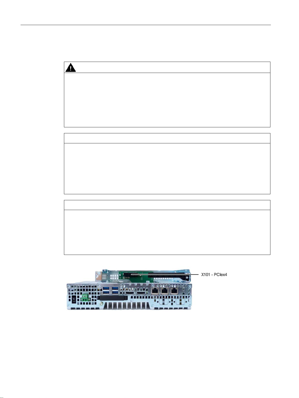
Expanding and assigning parameters to the device
6.3
Installing and removing PCIe cards
WARNING
Risk of fire through expansion cards
NOTICE
Points to note with expansion cards
NOTICE
Ambient conditions when using PCIe cards:
6.3 Installing and removing PCIe cards
Expansion cards generate additional heat. The device may overheat and cause a fire.
Please note the following:
• Observe the safety and installation instructions for the expansion cards.
• If in doubt, install the device in an enclosure that is compliant with requirements to
sections 4.6 and 4.7.3 of the EN 60950-1:2006 and IEC/UL/EN/DIN-EN 60950-1
standards.
Expansion cards may impose restrictions on the installation location (fire-proof enclosure)
and permitted mounting positions (see Technical specifications (Page 105)). If the device
has been fitted with expansion cards, please observe the safety and installation instructions
for the expansion cards in the corresponding documentation.
If in doubt, install the device in an enclosure that is compliant with IEC/UL/EN/DIN-EN
60950-1, sections 4.6 and 4.7.3.
Please observe the conditions of use regarding the ambient temperature when using PCIe
cards.
The temperature in the PCIe slot of the IPC is around 15 K higher than the ambient
temperature. This means the maximum permissible ambient temperature may be lower
than for the IPC427E alone.
Figure 6-1 Device version with one PCIe slot
SIMATIC IPC427E
68 Operating Instructions, 09/2017, A5E37454814-AB
Page 69

Expanding and assigning parameters to the device
Requirement
Procedure
Installation
Note
Observe the guidelines for handling electrostatic
"
6.3 Installing and removing PCIe cards
Figure 6-2 Device version with two PCIe slots
● The device is disconnected from the power supply.
● The device is open (see section "Opening the device containing expansion cards
(Page 63)").
● Blanking plates: If the PCIe card to be used has external interfaces, you can use these
blanking plates to install the connectors. You can also use a slot plate with connector
perforations.
● 1 T10 screwdriver
-sensitive components in section
ESD guideline (Page 98)".
SIMATIC IPC427E
Operating Instructions, 09/2017, A5E37454814-AB
69
Page 70
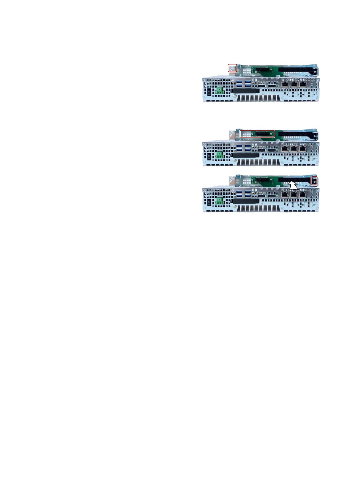
Expanding and assigning parameters to the device
1. Remove the screw in the blanking plate
for the slot you require and remove the
blanking plate.
2. Remove the retainer.
3. Insert the expansion card into the slot as
shown.
Secure the expansion card with the co
responding screw.
4. Slide the clamp in the direction indica
Secure the bracket with the
screw.
5. Close the device as specified in section "
(Page 63)".
Removal
Configuring BIOS setup
6.3 Installing and removing PCIe cards
r-
ted.
designated
Proceed in reverse order.
You may need to make settings in the BIOS Setup. For detailed information about
installation, please refer to the documentation provided with the specific expansion card.
Opening the device containing expansion cards
SIMATIC IPC427E
70 Operating Instructions, 09/2017, A5E37454814-AB
Page 71

Expanding and assigning parameters to the device
6.4
Assigning CPU power consumption parameters
Operating mode
Description
The maximum CPU power consumption is 17 W.
The maximum CPU power consumption is 25 W.
optimized
constant CPU frequency.
The maximum power consumption of the CPU is 12 W.
6.4 Assigning CPU power consumption parameters
The CPU can be switched to one of the following modes via a BIOS Setup setting (BIOS
setup > Menu "Power" > "Power&Performance" > "CPU Power Management Control" >
"CPU Power Level"):
Standard Default setting
The CPU clock is dynamically limited with maximum 3D graphics performance.
Performance
optimized
Determinism
Temperature
optimized
Setting the high performance for CPU and Graphics at the same time.
Same as standard, but additionally optimized for deterministic operation with
Setting for lowest power consumption.
The CPU clock is limited at a higher load.
SIMATIC IPC427E
Operating Instructions, 09/2017, A5E37454814-AB
71
Page 72

Expanding and assigning parameters to the device
6.4 Assigning CPU power consumption parameters
SIMATIC IPC427E
72 Operating Instructions, 09/2017, A5E37454814-AB
Page 73

7
7.1
Maintenance
Component
Replacement interval
CMOS backup battery
4 years
7.2
Repair information
Making repairs
WARNING
Opening the device
To maintain high system availability, we recommend that you replace PC components that
are subject to wear, at the intervals for replacement indicated in the table below.
Hard disk drive 3 years
Install only system expansions approved for this device. If you install other expansion
devices, you may damage the device or violate the safety requirements and regulations on
RF suppression. Contact your technical support team or where you purchased your PC to
find out which system expansion devices may safely be installed.
Unauthorized opening and improper repairs on the device may result in substantial damage
to equipment or endanger the user. If you install or replace a system expansion and
damage your device, the warranty will become void.
The device may only be repaired by qualified personnel.
SIMATIC IPC427E
Operating Instructions, 09/2017, A5E37454814-AB
73
Page 74
Device maintenance and repair
Safety when working in and on electrical systems
Note
These safety steps must always be taken in the above order before any work on electrical
systems. Once work on an electrical system is finished, cancel the safety steps starting with
the last and finishing with
NOTICE
Electrostatic-sensitive components
WARNING
Risk of explosion and release of harmful substances
7.2 Repair information
Work in or on electrical systems may only be carried out by authorized persons. The
following safety regulations apply in Germany for the prevention of electric shock and
electrocution:
1. Switch off the system
2. Secure the system to prevent it switching back on
3. Check the system to ensure it is de-energized
4. Ground and short the system
5. Cover or shield adjacent live parts
These safety rules are based on the DIN VDE 0105 standard.
the first.
In accordance with the applicable safety regulations, clearly indicate on an electrical system
that work on it is underway.
Observe the safety regulations applicable in the country of operation.
The device contains electronic components which are destroyed by electrostatic charges.
This can result in malfunctions and damage to the machine or plant.
Make sure you take precautionary measures even when you open the device, for example,
when opening device doors, device covers or the housing cover. For more information,
refer to the section "ESD Guideline (Page 98)"
Improper handling of lithium batteries can result in an explosion of the batteries. Explosion
of the batteries and the released pollutants can cause severe physical injury.
Observe all safety and handling instructions for lithium batteries. Do not expose lithium
batteries to flames and do not solder the battery cell. Do not recharge, open, or short
lithium batteries. Do not reverse lithium battery polarity or heat the batteries to over 100°C.
Keep lithium batteries out of direct sunlight and protect them from moisture and
condensation.
SIMATIC IPC427E
74 Operating Instructions, 09/2017, A5E37454814-AB
Page 75

Device maintenance and repair
NOTICE
Batteries and rechargeables pollute the environment
Limitation of liability
See also
7.3 Installing and removing hardware
Do not dispose of used batteries or rechargeables in household waste. Users are obliged
by law to return used batteries and rechargeable batteries. You as the user are legally
responsible disposing used batteries or rechargeables in a correct manner.
Observe the following rules for the disposal of batteries and rechargeables:
• Dispose of used batteries and rechargeable batteries separately as hazardous waste in
accordance with local regulations.
• You can take used batteries and rechargeable batteries to public collection points and
wherever batteries and rechargeable batteries of the type in question are sold.
• Mark used battery containers as "Used batteries".
All technical specifications and approvals for the device apply only if you use expansion
components that have a valid CE approval (CE marking). The installation instructions for
expansion components in the associated documentation must be observed.
UL approval of the device only applies when the UL-approved components are used
according to their "Conditions of Acceptability".
We are not liable for functional limitations caused by the use of third-party devices or
components.
Spare parts and repairs (http://support.automation.siemens.com/WW/view/en/16611927)
SIMATIC IPC427E
Operating Instructions, 09/2017, A5E37454814-AB
75
Page 76

Device maintenance and repair
7.3
Installing and removing hardware
7.3.1
Installing and removing the backup battery
Note
An empty backup battery impairs the function of the device. Replace the backup battery in
good time.
Replace the backup battery only with a battery of the same type or a type recommended by
Siemens.
The article number of the backup battery is A5E34734290.
Dispose of used batteries in accordance with local regulations.
Requirement
7.3 Installing and removing hardware
The service life of a backup battery is approximately 5 to 8 years, depending on the
operating conditions.
● The device is disconnected from the power supply.
● No peripherals such as a mouse, keyboard or monitor are connected.
● 1 T10 screwdriver
SIMATIC IPC427E
76 Operating Instructions, 09/2017, A5E37454814-AB
Page 77
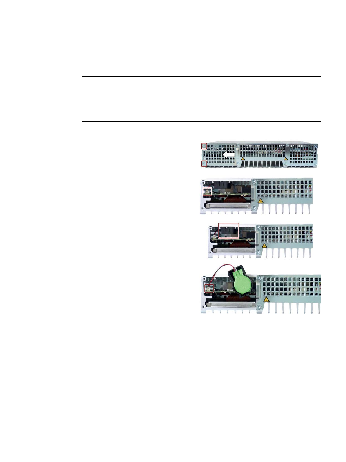
Device maintenance and repair
Procedure - Removal
NOTICE
Date and time setting are lost
1. Remove the indicated screws, pull the
cover panel in direction of
lift it off.
2.
Carefully remove the connector.
3. Remove the battery holder from the e
closure guide.
4. Remove the battery from the battery
ho
Procedure - Installation
7.3 Installing and removing hardware
The time setting is cleared if it takes more than 30 seconds to replace the battery. The
device time is no longer synchronized. Timer-controlled programs will no longer run or run
at the incorrect time. This may damage the plant.
Set the device time again.
the arrow and
Install the device by following the same steps in the reverse order.
n-
lder.
SIMATIC IPC427E
Operating Instructions, 09/2017, A5E37454814-AB
77
Page 78
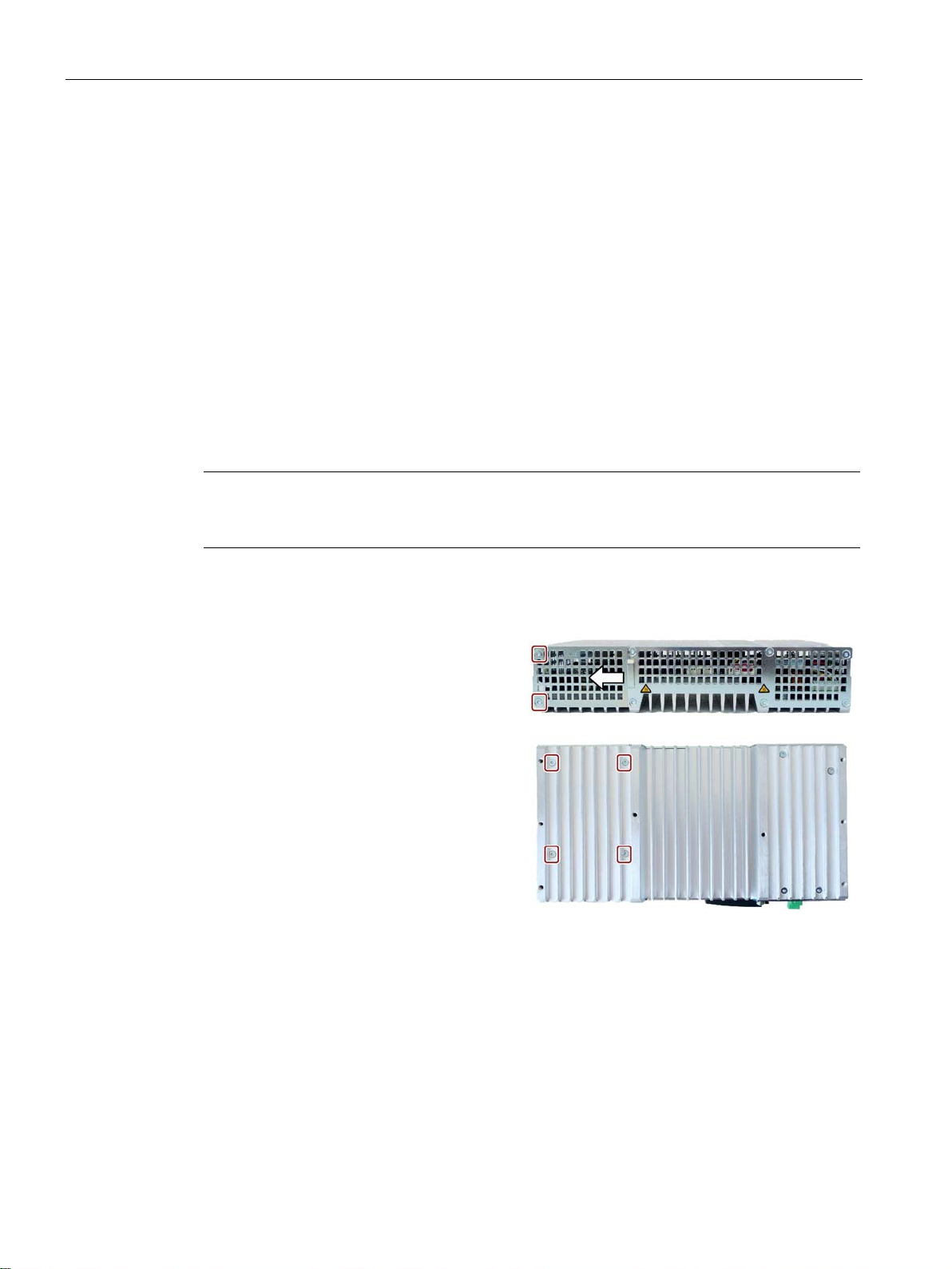
Device maintenance and repair
7.3.2
Changing storage media
7.3.2.1
Replacing a HDD/SSD
Requirement
Procedure
Note
Observe the guidelines for handling electrostatic
guideline
Removal
1. Remove the wall mounting bracket or the
vertical mounting
then the indicated screws.
Push the cover in the direction indicated
and lift it off.
2. Remove the marked screws.
These screws secure the HDD/SSD.
7.3 Installing and removing hardware
This procedure applies to the replacement of the built-in HDD or SSD.
● The device is disconnected from the power supply.
● The device is removed.
● 1 T10 screwdriver
-sensitive components in section "ESD
(Page 98)".
bracket, if any, and
SIMATIC IPC427E
78 Operating Instructions, 09/2017, A5E37454814-AB
Page 79
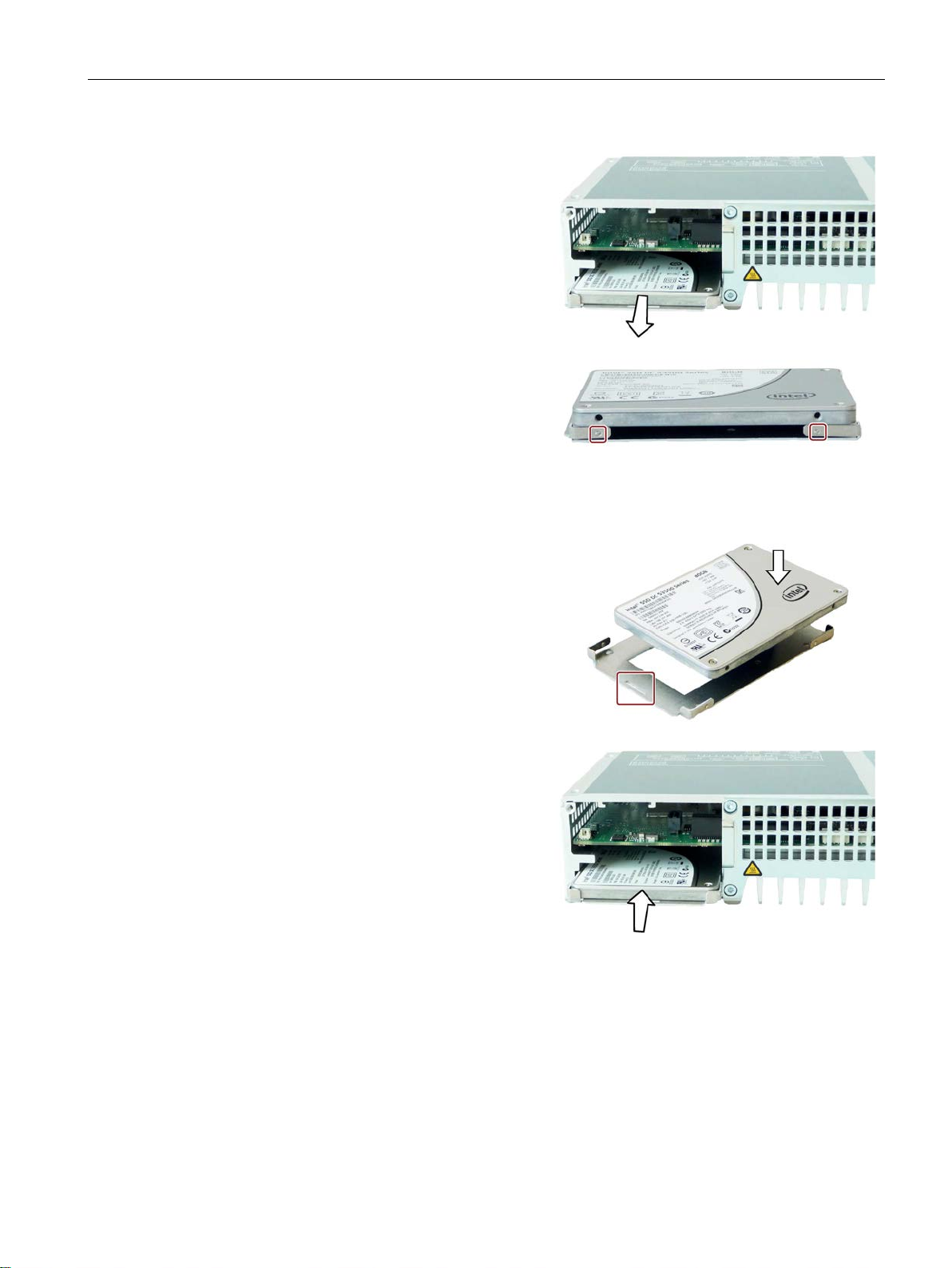
Device maintenance and repair
3. Remove the HDD/SSD from the encl
sure.
4. Loosen the HDD/SSD on the side from
the base plate as shown.
The HDD/SSD is retained on the base
plate b
additional insulating film is inserted into
the base plate for HDD operation.
Installation
1. Place the HDD/SSD onto the base plate.
Observe the recess position shown when
installing an SDD. The SSD interfaces
should be located opposite the recess.
2. Insert the new HDD/SSD into the encl
sure.
Take care that the nameplate
Slide the HDD/SSD into the enclosure
until you can see the mounting holes.
7.3 Installing and removing hardware
o-
y means of the studs shown. An
o-
is on top.
SIMATIC IPC427E
Operating Instructions, 09/2017, A5E37454814-AB
79
Page 80
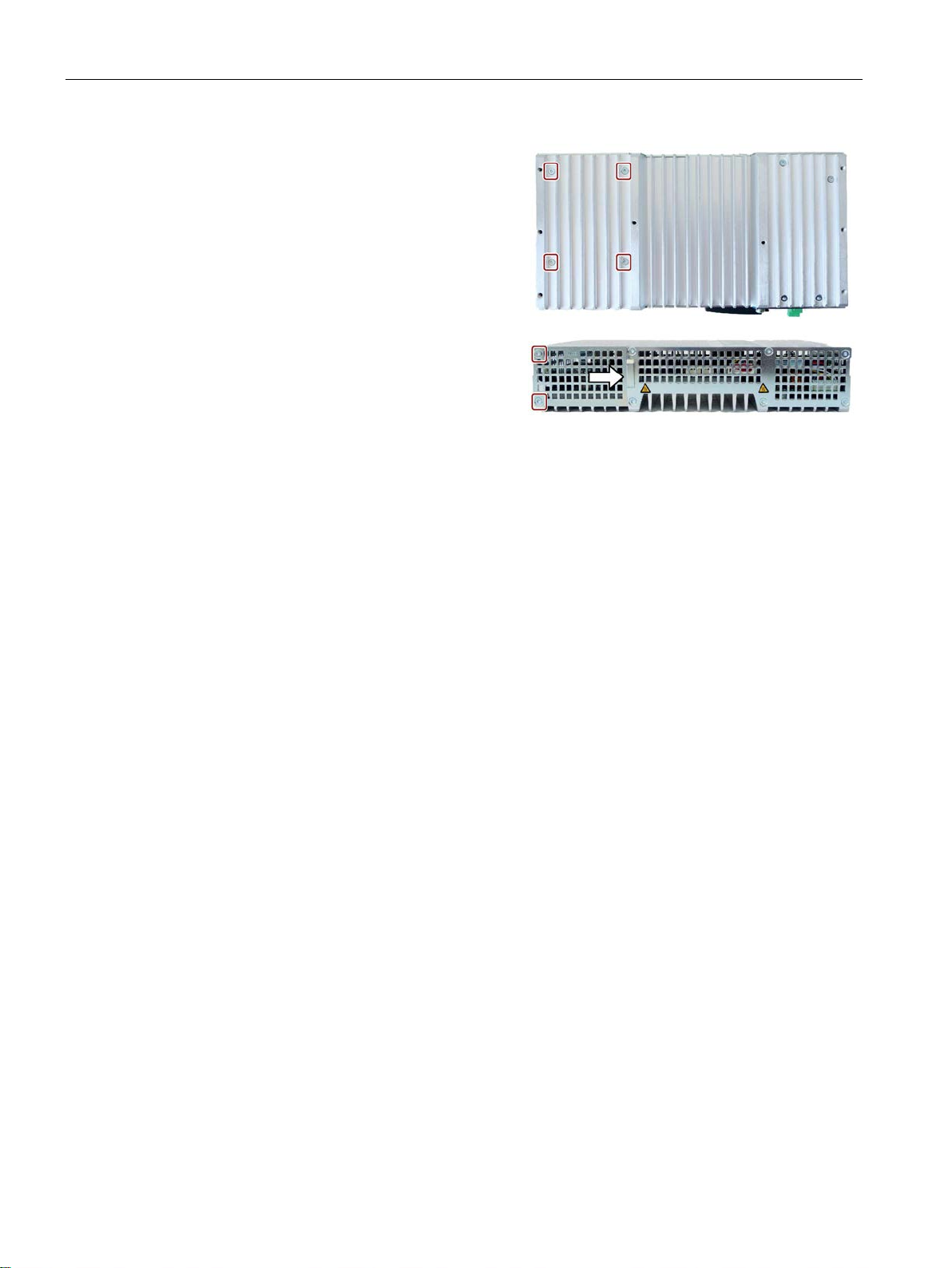
Device maintenance and repair
3. Turn in the marked screws.
4. Insert the cover into the
Turn in the marked screws.
7.3 Installing and removing hardware
enclosure.
SIMATIC IPC427E
80 Operating Instructions, 09/2017, A5E37454814-AB
Page 81

Device maintenance and repair
7.4
Installing the software
7.4.1
Reinstalling the operating system
Note
Further information on the delivered operating system can be found on the USB stick
provided.
7.4.1.1
General installation procedure
Note
Installing the operating system in UEFI mode
To install an operating system in UEFI mode, the USB stick must also be booted in UEFI
mode. Since Windows Embedded operating systems are installed in MBR mode, the USB
stick boots automatically for the Resto
Note
GPT partitioning with Windows 10
Please note that GPT partitioning should be selected for Windows 10 (GPT: GUID Partition
Table).
Recovery function (only with Windows 7 Ultimate and Windows 10)
NOTICE
Windows Embedded
7.4 Installing the software
If the supplied operating system is no longer functioning correctly, you can reinstall it from
the supplied USB stick:
● Using the Recovery function of the USB stick
● Using the Restore function of the USB stick
For these functions, set up the USB stick as bootable. To boot from the USB stick, "USB
Boot" must be set to "enabled" in the BIOS Setup.
re function in MBR mode (Legacy mode).
The Recovery function is not available for Windows Embedded operating systems.
The supplied USB contains the installation program with tools for configuring the drives and
installing the operating system with the supported languages.
The basic language of the installed operating system is English. To add other languages,
install these languages from the supplied USB stick ("Language packs" directory).
SIMATIC IPC427E
Operating Instructions, 09/2017, A5E37454814-AB
81
Page 82

Device maintenance and repair
Contents of the "DocuAndDrivers" directory
Restore function
7.4 Installing the software
The supplied USB stick contains the documentation, hardware drivers and updates.
In Windows, these contents are available via a menu.
If you have ordered IPC427E with operating system, the supplied USB stick contains the
Restore function.
SIMATIC IPC427E
82 Operating Instructions, 09/2017, A5E37454814-AB
Page 83

Device maintenance and repair
7.4.1.2
Restoring the factory state
NOTICE
Data are deleted
Procedure
Note
The "USB Boot" option has to be set to "Enabled" in the BIOS menu "Boot" so that the
device can boot from the USB stick.
7.4 Installing the software
You can restore the original factory software using the Restore function. The USB stick
contains the necessary images and tools for transferring the factory software to the hard
disk/SSD or memory card of your PC. The following options are available for restoring
software:
● Restore the entire hard disk / SSD or memory card with drive C: (system) and drive D:
Use the "Restore entire hard disk" option.
● Restore drive C: only This allows you to retain any user data on drive D: Use the "Restore
system partition only" option.
When you select the "Restore entire hard disk" option, all data, user settings and
authorizations or license keys on the hard disk are lost. The hard disk is reset to the
delivery state with partitions "C:" and "D:".
If the "Restore system partition only" option is set, all files on drive C: (System) are deleted.
All data, user settings and existing authorizations or license keys on drive "C:" will be lost.
Drive "C:" on the hard drive is completely erased, reformatted and the original software is
written to it.
1. Connect the USB stick to the device.
2. Restart the device.
3. Press <ESC> when the following BIOS message appears:
Press Esc for Boot Options
The BIOS selection menu is displayed when initialization is completed.
4. To boot from the USB stick, select the Boot Manager.
5. Select the USB stick in the Boot Manager and confirm the entry.
6. Select the Restore function and confirm the entry.
7. Follow the on-screen instructions.
SIMATIC IPC427E
Operating Instructions, 09/2017, A5E37454814-AB
83
Page 84

Device maintenance and repair
7.4.1.3
Windows 7 / Windows 10
Installing Windows
Note
Windows 10
Specific information on using the Windows
manuals (not included in the scope of delivery):
•
•
•
Note
Windows 7
Specific information on using the Windows
manual (not included in the product package): Microsoft Windows 7
(MS Press No. 5927).
Requirement
Procedure
Note
The "USB Boot" option has to be set to "Enabled" in the BIOS menu "Boot" so that
device can boot from the USB stick.
7.4 Installing the software
operating systems is available in the following
Windows 10 - Step by Step (MS Press No. 324)
Windows 10 Plain and Simple (MS Press No. 422)
Windows 10 Inside Out (MS Press No. 325 / MS Press No. 418)
operating systems is available in the following
- Technical Reference
● USB keyboard and monitor
● Supplied USB stick with Recovery function
the
1. Connect the USB stick to the device.
2. Restart the device.
3. Press <ESC> when the following BIOS message appears:
Press Esc for Boot Options
The BIOS selection menu is displayed when initialization is completed.
4. To boot from the USB stick, select the Boot Manager.
5. Select the USB stick in the Boot Manager and confirm the entry.
6. Select the Recovery function and confirm the entry.
SIMATIC IPC427E
84 Operating Instructions, 09/2017, A5E37454814-AB
Page 85

Device maintenance and repair
NOTICE
Data deleted
"Install Windows" installation program
Setting up partitions under Windows
Setting up the language selection by means of the Multilanguage User Interface (MUI)
7.4 Installing the software
7. Follow the on-screen instructions.
After a few seconds, you will see the "Install Windows" installation program.
All data, user settings and existing authorizations or license keys are deleted during the
installation of Windows 7 and Windows 10.
• Back up all data.
• Check the data and time in the BIOS setup, "Main" menu and correct the displayed
time if necessary.
8. Now follow the instructions of the installation program "Install Windows". You will find
additional information in the operating system manual.
The language of the installation program and the operating system you want to install has
been preset to English. You can change the language of the operating system after the
installation. You can find information on this in section: "Setting up the language selection by
means of the Multilanguage User Interface (MUI) (Page 85)".
You can set up partitions during the installation process.
The recommended minimum size for Windows system partition varies, depending on the
amount of RAM and additional software that you are going to use. Information about the
partitioning of the data volume in the delivery state is available in section Setting up the
partitions under Windows 7 Ultimate and Windows 10 (Page 90).
You can set the display of menus, dialogs or other information, such as date and time, to a
different language. For this purpose, you can either select one of the preinstalled languages
or install a new language package.
The following command sequences are described in English. Depending on the default
setting, they can be displayed in another language.
SIMATIC IPC427E
Operating Instructions, 09/2017, A5E37454814-AB
85
Page 86

Device maintenance and repair
Setting up language selection
Changing the settings for language, region and formats of a registered user account
Changing the settings for language, region and formats of the system account and the
standard user account
Installing new language packages
The following languages can be installed at a later time:
Language
Windows 7 / 10
German
X
English
X
French
X
Spanish
X
Chinese (Hong Kong)
X
Chinese (simplified)
X
Chinese (Taiwan)
X
Japanese
X
Russian
X
7.4 Installing the software
1. Choose:
"Start > Control Panel > Clock, Language, and Region > Regional and Language
Options"
2. You can make the desired changes in the "Formats", "Location" and "Keyboards and
Languages" tabs.
You can change the settings for language, region and formats of the system account (for
example, the language in the user login dialog) and the settings of the standard user account
(standard setting for new users). The settings of the registered user are copied to the system
account and the standard user account for this purpose.
1. Choose:
"Start > Control Panel > Clock, Language, and Region > Regional and Language
Options"
2. You can make the required changes in the "Administrative" tab. You copy the settings by
clicking the respective button.
Some language packages are available on the Recovery section of the USB stick in the
"Language packs" folder.
1. Choose:
"Start > Control Panel > Clock, Language, and Region > Regional and Language
Options"
2. Select the "Keyboards and Languages" tab.
3. Click the "Install/uninstall languages" button and make the required changes.
Italian X
SIMATIC IPC427E
86 Operating Instructions, 09/2017, A5E37454814-AB
Page 87

Device maintenance and repair
7.4.1.4
Windows Embedded Standard
General installation procedure
Note
You require a USB keyboard, a monitor and the supplied USB stick to reinstall the operating
system. Before performing the new installation, you should check the date and time set in
the BIOS Setup, "Main" menu, and
To be able to use the Enhanced Write Filter (EWF), the operating system must be installed
in MBR mode.
Language selection in Windows Embedded Standard 7
Note
Note the license terms of Windows Embedded Standard 7
Note the license terms for Windows Embedded Standard
software terms of the Siemens
You can find the license terms in the delivered document "MICROSOFT SOFTWARE
LICENSE TERMS for Windows
\
7.4 Installing the software
If your software becomes corrupt for any reason, you can reinstall it using the supplied USB
stick. The USB stick contains an image file for the device memory with the original software
package (operating system with installed hardware drivers).
correct these if necessary.
You can change the language using the supplied USB stick. The USB stick contains the
required language packages and help for changing the system language.
Windows\System32\license.rtf.
7 and especially the extended
AG.
Embedded Standard 7" and in the system drive under
SIMATIC IPC427E
Operating Instructions, 09/2017, A5E37454814-AB
87
Page 88

Device maintenance and repair
Procedure - Change system language
7.4 Installing the software
1. Connect the supplied USB stick to a free USB port of the device.
2. Restart the device and press "ESC" to access the BIOS.
3. Switch to the "Boot" menu and select the setting "USB Boot" = "Enabled".
4. Switch to the "Exit" menu and select "Exit Saving Changes".
5. Restart the device and press the "ESC" key and then enter the "Boot Manager" menu.
6. In the "Legacy USB" area, select the boot menu of the USB stock and press "Enter" to
boot from this.
7. Follow the instructions on the screen.
8. After selecting the menu dialog language, select the menu entry "Manage language
packages".
Depending on the current language setup, you have the following options in the "Manage
language packages" menu:
– Display language settings
– Install language
– Change language
– Uninstall installed language
SIMATIC IPC427E
88 Operating Instructions, 09/2017, A5E37454814-AB
Page 89

Device maintenance and repair
7.4.2
Partitioning the data storage medium
7.4.2.1
Partitioning in Windows Embedded Standard 7
Partitioning of the SIMATIC IPC CFast card
Partition
Name
Size of the card
File system
8 GB
16 GB
30 GB
der
Partition
Name
Size of the card
File system
16 GB
30 GB
First
SYSTEM
13 GB
25 GB
NTFS compressed
Second
DATA
Remainder
Remainder
NTFS compressed
Partitioning of the HDD or SSD
Partition
Name
Partition size
File system
< 100 GB
> 100 GB
First
System
60 GB
100 GB
NTFS not compressed
Second
Data
Remainder
Remainder
NTFS not compressed
SIMATIC IPC Image & Partition Creator.
7.4 Installing the software
You will need to reconfigure the partitions after installing a new drive, to repair corrupt
partitions or to change the partitioning.
The SIMATIC IPC CFast card for Windows Embedded Standard 7 comes configured with
the following default partitions:
Table 7- 1 32-bit versions of the operating system
First SYSTEM 6 GB 12 GB 25 GB NTFS not compressed
Second DATA Remainder Remainder Remain-
* Due to partitioning/formatting, the actual CFast capacity does not correspond to the
memory size specified on the SIMATIC IPC CFast card.
Table 7- 2 64-bit versions of the operating system
NTFS not compressed
SIMATIC IPC427E
Operating Instructions, 09/2017, A5E37454814-AB
* Due to partitioning/formatting, the actual CFast capacity does not correspond to the
memory size specified on the SIMATIC IPC CFast card.
In the delivery state, the following partitions are configured on the HDD or SSD drive with the
Windows Embedded Standard 7 operating system:
Table 7- 3 Size of the HDD/SSD
To restore the partitions to their original delivery state, we recommend the software
Additional information is available in the
accompanying documentation.
89
Page 90

Device maintenance and repair
7.4.2.2
Setting up the partitions under Windows 7 Ultimate and Windows 10
Partitioning of the HDD or SSD
Partition
Name
Partition size
File system
SSD: > 60 GB
SSD/HDD: > 100 GB
Second
MSR
128 MB
None
Third
System
60 GB
100 GB
NTFS, not compressed
Fourth
Data
Remainder
NTFS, not compressed
Partition
Name
Partition size
File system
SSD: > 60 GB
SSD/HDD: > 100 GB
First
Boot
260 MB
FAT32
Second
MSR
128 MB
None
Third
System
60 GB
100 GB
NTFS, not compressed
Fourth
WinRE
500 MB
NTFS, not compressed
Fifth
Data
Remainder
NTFS, not compressed
7.4 Installing the software
You will need to reconfigure the partitions after installing a new drive, to repair corrupt
partitions or to change the partitioning.
In the factory state, the following partitions are set up on the HDD or SSD for the
Windows 7 x64 UEFI operating system:
Primary Boot 260 MB FAT32
In the factory state, the following partitions are set up on the HDD or SSD for the
Windows 10 UEFI operating system:
SIMATIC IPC427E
90 Operating Instructions, 09/2017, A5E37454814-AB
Page 91

Device maintenance and repair
7.4.2.3
Adapting the partitions under Windows 7 Ultimate and Windows 10
NOTICE
Data lost in the case of deleting a partition!
Requirement
Procedure - Reduce partition
Procedure - Increase partition
Note
To increase a partition, this partition must not be formatted with a file system or the partition
must be formatted with an
7.4 Installing the software
With the disk management, you can adapt the partitioning of your drives.
You can reduce or delete an available partition to acquire unassigned memory space, which
you can use to set up a new partition or to increase an existing partition.
If you delete a partition, all the data on this partition is lost.
Back up your data before you change partitions.
You are logged on as an administrator.
A partition can only be reduced if sufficient space is available.
1. Click with the right mouse button on the partition to be reduced and click on "Reduce
size".
2. Follow the instructions.
1. Click in the partition manager with the right mouse button on the partition to be increased
and click on "Increase size".
2. Follow the instructions on the screen.
Additional information is available in the "Help" menu under "Help topics" and "Search".
"NTFS" file system.
SIMATIC IPC427E
Operating Instructions, 09/2017, A5E37454814-AB
91
Page 92

Device maintenance and repair
7.4.3
Installing drivers and software
Note
In the case of multilingual operating systems (MUI versions), you must set the menus and
dialogs and the default language to English (US) in the regional settings before new drivers
and operating system updates are installed.
You can install a second lang
supplied USB stick under Windows Embedded Standard 7.
Procedure
Note
For a new installation of Windows operating systems, the chips
before all other drivers, if required.
7.4 Installing the software
uage package for service purposes at a later time with the
1. Connect the supplied USB stick to the USB port.
2. Start the program "START_DocuAndDrivers".
3. Select "Drivers" in the index.
4. Select the device and operating system.
5. Select the required driver.
6. Open the folder with the driver data by clicking on the link next to "Driver path".
7. Start the setup program in this folder.
et driver must be installed
SIMATIC IPC427E
92 Operating Instructions, 09/2017, A5E37454814-AB
Page 93

Device maintenance and repair
7.4.4
Update installation
7.4.4.1
Updating the operating system
Windows
Note
Before you install new drivers or operating system updates for Windows MUI versions,
configure the regional menu and dialog settings and the default English (US) language.
other operating systems
7.4.4.2
Installing or updating application programs and drivers
7.4.5
Backing up data
SIMATIC IPC Image & Partition Creator
SIMATIC IPC Image & Partition Creator
7.5
Recycling and disposal
7.5 Recycling and disposal
The latest updates for the Windows operating system are available on the Internet at
Microsoft (http://www.microsoft.com) and on the device in the Start menu "Start > All
Programs > Windows Update > Check for updates".
Contact the corresponding manufacturer.
Drivers for USB sticks are included in the operating system and do not have to be installed
separately.
For information about installation of SIMATIC software packages, refer to the corresponding
manufacturer documentation.
For updates of third-party drivers and application programs, contact the respective
manufacturer.
We recommend the software tool
back up data under Windows. This tool provides convenient and efficient functions for
backing up and restoring the full content of memory cards, hard disks and individual
partitions (images).
The
ordering system (https://mall.industry.siemens.com). For more information about SIMATIC
IPC Image & Partition Creator, refer to its product documentation.
can be ordered using the Siemens online
(as of V3.4) to
The devices described in these operating instructions can be recycled thanks to their low
level of pollutants. Contact a certified disposal service company for environmentally sound
recycling and disposal of your old devices.
SIMATIC IPC427E
Operating Instructions, 09/2017, A5E37454814-AB
93
Page 94

Device maintenance and repair
7.5 Recycling and disposal
SIMATIC IPC427E
94 Operating Instructions, 09/2017, A5E37454814-AB
Page 95

8
8.1
Certificates and approvals
ISO 9001 certificate
Software license agreements
UL approval
The Siemens quality management system for our entire product creation process
(development, production and sales) meets the requirements of ISO 9001:2008.
This has been certified by DQS (the German society for the certification of quality
management systems).
Certificate no.: 001323 QM08
If the device is supplied with preinstalled software, you must observe the corresponding
license agreements.
The following approvals are available for the device:
● Underwriters Laboratories (UL) in accordance with standard UL 60950-1 Second Edition
(I.T.E.)
● Underwriters Laboratories (UL) in accordance with standard UL508 (IND.CONT.EQ)
● Canadian National Standard CAN/CSA-C22.2 No. 60950-1-07
● Canadian National Standard CAN/CSA-C22.2 No. 142
SIMATIC IPC427E
Operating Instructions, 09/2017, A5E37454814-AB
95
Page 96
Technical specifications
FCC (USA) and ICES (Canada) Compliance
USA
A digital device, pursuant to Part 15 of the FCC Rules. These limits are designed
ment is operated in a commercial environment. This equipment generates, uses,
ference at his own expense.
FCC regulations.
void the user's authority to operate the equipment.
following two conditions: (1) this device may not cause harmful interference, and
may cause undesired operation.
CANADA
Canadian Notice
This Class A digital apparatus complies with Canadian ICES-003 (B).
003 (B) du Canada.
RCM AUSTRALIA/NEW ZEALAND
KOREA
8.1 Certificates and approvals
Federal Communications Commission
Radio Frequency
Interference
Statement
Shielded Cables Shielded cables must be used with this equipment to maintain compliance with
Modifications Changes or modifications not expressly approved by the manufacturer could
Conditions of
Operations
Avis Canadien Cet appareil numérique de la classe A est conforme à la norme NMB-
This equipment has been tested and found to comply with the limits for a Class
to provide reasonable protection against harmful interference when the equip-
and can radiate radio frequency energy and, if not installed and used in accordance with the instruction manual, may cause harmful interference to radio communications. Operation of this equipment in a residential area is likely to cause
harmful interference in which case the user will be required to correct the inter-
This device complies with Part 15 of the FCC Rules. Operation is subject to the
(2) this device must accept any interference received, including interference that
This product meets the requirements of EN 61000-6-3 Generic standards - Emission
standard for residential, commercial and light-industrial environments.
This product meets the requirements of the standard EN 61000-6-3 Generic standards Emission standard for residential, commercial and light-industrial environments.
This product meets the requirements of Korean certification.
This product satisfies the requirement of the Korean Certification (KC Mark).
이 기기는 업무용(A급) 전자파 적합기기로서 판매자 또는 사용자는 이 점을 주의하시기
바라며 가정 외의 지역에서 사용하는 것을 목적으로 합니다.
SIMATIC IPC427E
96 Operating Instructions, 09/2017, A5E37454814-AB
Page 97

Technical specifications
8.2
Declaration of conformity
8.2.1
CE marking
EU Declaration of Conformity
8.2.2
Electromagnetic compatibility, Industrial and Residential Areas
Electromagnetic compatibility
Scope of application
Requirements for
Interference emission
Immunity to interference
Industrial area
EN 61000-6-4
EN 61000-6-2
and small businesses
RoHs directive
8.2 Declaration of conformity
The device meets the guidelines listed in the following sections.
The associated declaration of conformity is available on the Internet at the following address:
EC Declaration of Conformity, UL approval Canada/USA
(https://support.industry.siemens.com/cs/ww/en/ps/23703).
This product meets the requirements of EC Directive 2014/30/EU "Electromagnetic
Compatibility".
The device is designed for the following areas of application corresponding to the CE
marking:
Residential and commercial areas
This product meets the requirements stated in the RoHS directive (Restriction of Hazardous
Materials): 2011/65/EU
Compliance with the directive has been reviewed according to the following standard:
EN 50581
EN 61000-6-3 EN 61000-6-1
SIMATIC IPC427E
Operating Instructions, 09/2017, A5E37454814-AB
97
Page 98

Technical specifications
8.3
Directives and declarations
8.3.1
ESD guideline
What does ESD mean?
NOTICE
Damage to ESD from touch
8.3 Directives and declarations
An electronic module is equipped with highly integrated components. Due to their design,
electronic components are highly sensitive to overvoltage and thus to the discharge of static
electricity. Such electronic components or modules are labeled as electrostatic sensitive
devices.
The following abbreviations are commonly used for electrostatic sensitive devices:
● ESD – Electrostatic sensitive device
● ESD – Electrostatic Sensitive Device as a common international designation
Electrostatic sensitive devices can be labeled with an appropriate symbol.
Electrostatic sensitive devices, ESD, can be destroyed by voltages which are far below the
human perception limit. If you touch a component or electrical connections of a module
without discharging any electrostatic energy, these voltages may arise.
The damage to a module by an overvoltage can often not be immediately detected and only
becomes evident after an extended period of operation. The consequences are incalculable
and range from unforeseeable malfunctions to a total failure of the machine or system.
Avoid touching components directly. Make sure that persons, the workstation and the
packaging are properly grounded.
SIMATIC IPC427E
98 Operating Instructions, 09/2017, A5E37454814-AB
Page 99
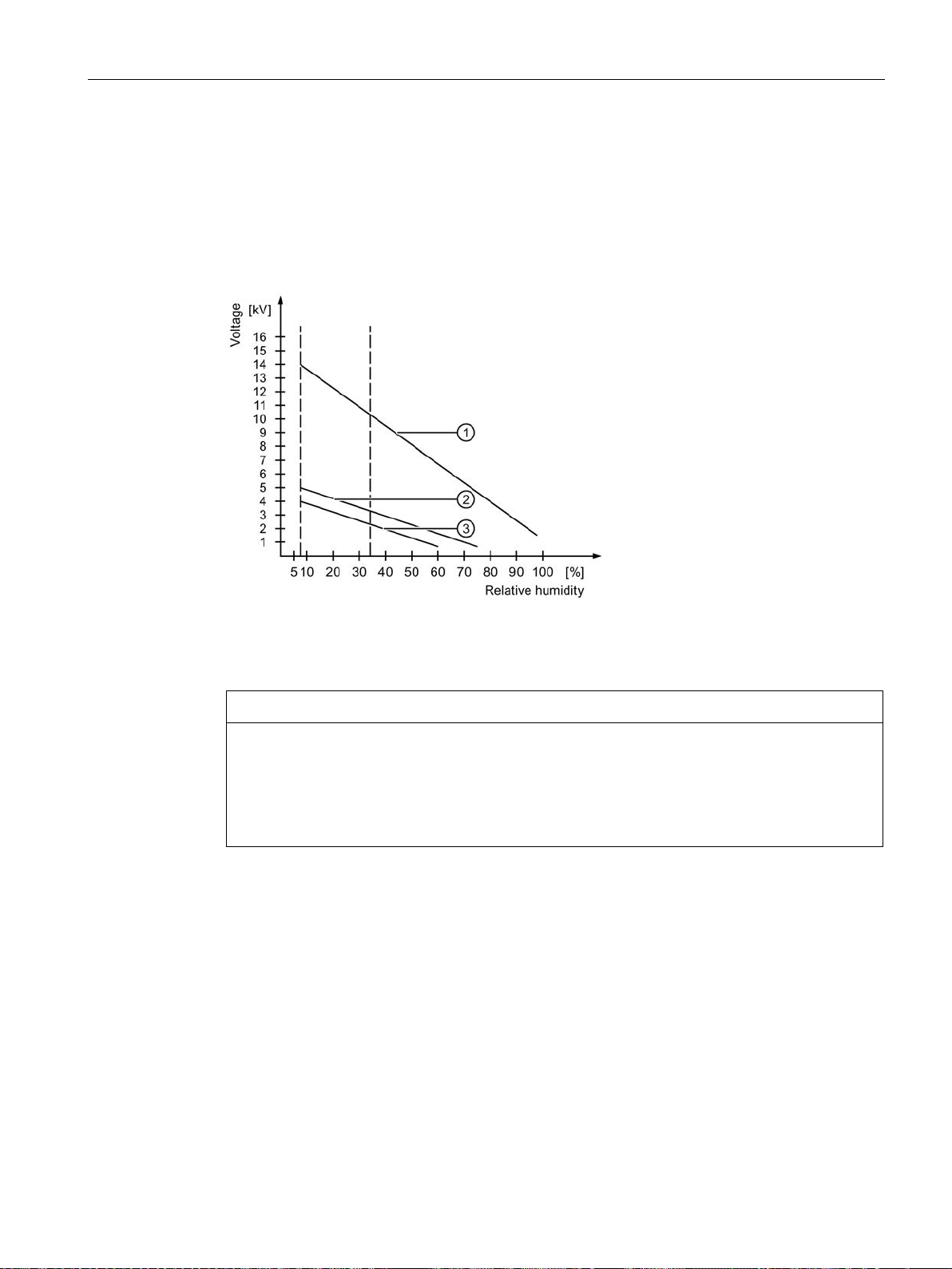
Technical specifications
Charge
①
Synthetic materials
②
Wool
③
Antistatic materials such as wood or concrete
NOTICE
Grounding measures
8.3 Directives and declarations
Every person without a conductive connection to the electrical potential of his/her
surroundings can be electrostatically charged.
The material with which this person comes into contact is of particular significance. The
figure shows the maximum electrostatic voltages with which a person is charged, depending
on humidity and material. These values conform to the specifications of IEC 61000-4-2.
There is no equipotential bonding without grounding. An electrostatic charge is not
discharged and may damage the ESD.
Protect yourself against discharge of static electricity. When working with electrostatic
sensitive devices, make sure that the person and the workplace are properly grounded.
SIMATIC IPC427E
Operating Instructions, 09/2017, A5E37454814-AB
99
Page 100

Technical specifications
Protective measures against discharge of static electricity
8.3 Directives and declarations
● Disconnect the power supply before you install or remove modules which are sensitive to
ESD.
● Pay attention to good grounding:
– When handling electrostatical sensitive devices, make sure that persons, the
workstation and devices, tools and packaging used are properly grounded. This way
you avoid static discharge.
● Avoid direct contact:
– As a general rule, do not touch electrostatic sensitive devices, except in the case of
unavoidable maintenance work.
– Hold the modules at their edge so that you do not touch the connector pins or
conductor paths. This way, the discharge energy does not reach and damage the
sensitive components.
– Discharge your body electrostatically before you take a measurement at a module. Do
so by touching grounded metallic parts. Always use grounded measuring instruments.
SIMATIC IPC427E
100 Operating Instructions, 09/2017, A5E37454814-AB
 Loading...