

Siemens SIMATIC IFP Basic Series, SIMATIC IFP1200 Basic, SIMATIC IFP1500 Basic, SIMATIC IFP1900 Basic, SIMATIC IFP2200 Basic Operating Instructions Manual
Page 1

IFP Basic
SIMATIC HMI
Industrial Flat Panels Basic
IFP Basic
Operating Instructions
03/2019
A5E46178354
Preface
Overview
1
Safety information
2
Installing and connecting the
device
3
Commissioning the device
4
Operating the device
5
Maintaining and servicing
your device
6
Technical information
7
Technical Support
A
Markings and symbols
B
List of abbreviations
C
- AB
Page 2
Siemens AG
Division Digital Factory
Postfach 48 48
90026 NÜRNBERG
GERMANY
Document order number: 6AV7862-2BC00-0AA0;6AV7862-2BD000AA0;6AV7862
Ⓟ
Copyright © Siemens AG 2019.
All rights reserved
Legal information
Warning notice system
DANGER
indicates that death or severe personal injury will result if proper precautions are not taken.
WARNING
indicates that death or severe personal injury may result if proper precautions are not taken.
CAUTION
indicates that minor personal injury can result if proper precautions are not taken.
NOTICE
indicates that property damage can result if proper precautions are not taken.
Qualified Personnel
personnel qualified
Proper use of Siemens products
WARNING
Siemens products may only be used for the applications described in the catalog and in the relevant technical
ambient conditions must be complied with. The information in the relevant documentation must be observed.
Trademarks
Disclaimer of Liability
This manual contains notices you have to observe in order to ensure your personal safety, as well as to prevent
damage to property. The notices referring to your personal safety are highlighted in the manual by a safety alert
symbol, notices referring only to property damage have no safety alert symbol. These notices shown below are
graded according to the degree of danger.
If more than one degree of danger is present, the warning notice representing the highest degree of danger will
be used. A notice warning of injury to persons with a safety alert symbol may also include a warning relating to
property damage.
The product/system described in this documentation may be operated only by
task in accordance with the relevant documentation, in particular its warning notices and safety instructions.
Qualified personnel are those who, based on their training and experience, are capable of identifying risks and
avoiding potential hazards when working with these products/systems.
Note the following:
documentation. If products and components from other manufacturers are used, these must be recommended
or approved by Siemens. Proper transport, storage, installation, assembly, commissioning, operation and
maintenance are required to ensure that the products operate safely and without any problems. The permissible
All names identified by ® are registered trademarks of Siemens AG. The remaining trademarks in this publication
may be trademarks whose use by third parties for their own purposes could violate the rights of the owner.
We have reviewed the contents of this publication to ensure consistency with the hardware and software
described. Since variance cannot be precluded entirely, we cannot guarantee full consistency. However, the
information in this publication is reviewed regularly and any necessary corrections are included in subsequent
editions.
for the specific
04/2019 Subject to change
-2BE00-0AA0;6AV7862-2BF00-0AA0
Page 3

Preface
Basic knowledge required
Scope of the operating instructions
Product name
MLFB
SIMATIC IFP1200 Basic
6AV7862-2BC00-0AA0
SIMATIC IFP1500 Basic
6AV7862-2BD00-0AA0
SIMATIC IFP2200 Basic
6AV7862-2BF00-0AA0
Scope of this documentation
Conventions
These operating instructions contain all the information you need for commissioning and
operation of the SIMATIC Industrial Flat Panels (IFP) Basic.
It is intended both for programming and testing personnel who commission the device and
connect it with other units (automation systems, programming devices), as well as for service
and maintenance personnel who install add-ons or carry out fault/error analyses.
A solid background in personal computers and Microsoft operating systems are required to
understand this manual. General knowledge in the field automation control engineering is
recommended.
These operating instructions apply to the following Industrial Flat Panels:
SIMATIC IFP1900 Basic
The SIMATIC IFP Basic is supplied with the following documents:
● In printed form: Quick Install Guide which includes the device description, installation and
commissioning Instructions.
● Electronically as PDF file on the "Tools, Drivers, and Documentation" DVD: SIMATIC IFP
Basic operating instructions.
● Electronically as PDF that can be download from Product Support in SIOS. The updates
of the document will be published in SIOS.
In these operating instructions, the SIMATIC IFP Basic is also referred to as "IFP Basic" or
"device".
6AV7862-2BE00-0AA0
A touch device generally refers to a device with a touch screen, as opposed to a pure
"display device". Touch screen is the general term for a capacitive multi-touch screen and
resistive single touch screen.
IFP Basic
Operating Instructions, 03/2019, A5E46178354 - AB
3
Page 4

Preface
Figures
History
Edition
Comment
03/2019
First Edition
At some places in these operating instructions, the general term "Windows Embedded
Standard" is used to refer to "Windows Embedded Standard 7" . "Windows 7" is used as an
abbreviation for "Windows 7 Ultimate".
This manual contains figures of the described devices. The supplied device may differ in
some details from the figures. Within some of the figures, one device is used to represent all
SIMATIC IFP Basic.
IFP Basic
4 Operating Instructions, 03/2019, A5E46178354 - AB
Page 5

Table of contents
Preface ................................................................................................................................................... 3
1 Overview................................................................................................................................................. 7
2 Safety information ................................................................................................................................. 12
3 Installing and connecting the device ...................................................................................................... 18
4 Commissioning the device .................................................................................................................... 39
5 Operating the device ............................................................................................................................. 40
1.1 Product description ................................................................................................................... 7
1.2 Scope of delivery ...................................................................................................................... 8
1.3 Exterior design .......................................................................................................................... 9
1.3.1 IFP Basic ................................................................................................................................... 9
1.3.2 Interfaces ................................................................................................................................ 10
1.4 Accessories ............................................................................................................................. 11
2.1 General safety instructions ..................................................................................................... 12
2.2 Data protection ........................................................................................................................ 14
2.3 Notes about usage .................................................................................................................. 14
3.1 Preparing for installation ......................................................................................................... 18
3.1.1 Checking the delivery package ............................................................................................... 18
3.1.2 Identification data of the device .............................................................................................. 20
3.1.3 Permitted mounting positions ................................................................................................. 21
3.1.4 Preparing the mounting cutout ................................................................................................ 22
3.1.5 Checking clearances............................................................................................................... 24
3.2 Installing the IFP Basic ........................................................................................................... 25
3.2.1 Notes on installation................................................................................................................ 25
3.2.2 Secure with mounting clips ..................................................................................................... 26
3.2.3 Fastening a device using a VESA adapter ............................................................................. 28
3.3 Connecting the device ............................................................................................................ 30
3.3.1 Notes on connection ............................................................................................................... 30
3.3.2 Earthing the device ................................................................................................................. 32
3.3.3 Connecting devices with 24 VDC 2-pin .................................................................................. 33
3.3.4 Connecting IFP Basic to a PC ................................................................................................ 35
3.3.5 Connecting a USB device ....................................................................................................... 36
3.4 Installing the tool and driver .................................................................................................... 36
5.1 Operator input options ............................................................................................................ 40
5.2 Operating a device with resistive single touch screen ............................................................ 41
5.3 Using the Brightness Adjustment Tool.................................................................................... 42
5.4 Using the touch driver ............................................................................................................. 43
IFP Basic
Operating Instructions, 03/2019, A5E46178354 - AB
5
Page 6

Table of contents
6 Maintaining and servicing your device ................................................................................................... 47
7 Technical information ............................................................................................................................ 49
A Technical Support ................................................................................................................................. 68
B Markings and symbols .......................................................................................................................... 70
C List of abbreviations .............................................................................................................................. 72
Glossary ............................................................................................................................................... 73
Index .................................................................................................................................................... 75
6.1 General information on maintenance and servicing .............................................................. 47
6.2 Cleaning the screen ............................................................................................................... 47
6.3 Spare parts and repairs ......................................................................................................... 48
6.4 Recycling and disposal .......................................................................................................... 48
7.1 Certificates and approvals ..................................................................................................... 49
7.2 Directives and declarations .................................................................................................... 51
7.2.1 ESD guideline ........................................................................................................................ 51
7.3 Dimension drawings ............................................................................................................... 54
7.3.1 Dimension drawing of the IFP1200 Basic .............................................................................. 54
7.3.2 Dimension drawing of the IFP1500 Basic .............................................................................. 55
7.3.3 Dimension drawing of the IFP1900 Basic .............................................................................. 56
7.3.4 Dimension drawing of the IFP2200 Basic .............................................................................. 57
7.4 Rating plate ............................................................................................................................ 58
7.5 Technical specifications ......................................................................................................... 58
7.5.1 General technical specifications ............................................................................................ 58
7.5.2 Ambient conditions ................................................................................................................. 60
7.5.2.1 Transport and storage conditions .......................................................................................... 60
7.5.2.2 Operating conditions .............................................................................................................. 61
7.5.2.3 Electromagnetic compatibility ................................................................................................ 62
7.5.2.4 Information on protection class and degree of protection ...................................................... 64
7.6 Interface description ............................................................................................................... 65
7.6.1 VGA interface ......................................................................................................................... 65
7.6.2 24 VDC Power Supply ........................................................................................................... 65
7.6.3 DisplayPort ............................................................................................................................. 66
7.6.4 USB interface, Type B ........................................................................................................... 67
7.6.5 USB interface, Type A ........................................................................................................... 67
A.1 Service and support ............................................................................................................... 68
A.2 Troubleshooting ..................................................................................................................... 69
B.1 Safety-relevant symbols ......................................................................................................... 70
IFP Basic
6 Operating Instructions, 03/2019, A5E46178354 - AB
Page 7
1
1.1
Product description
Features
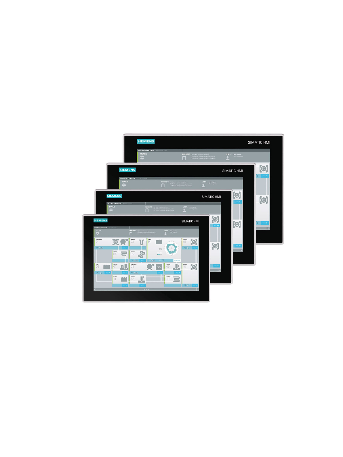
SIMATIC IFP Basic are touch monitors suitable for industrial use with a brilliant TFT (Thin
Film Transistor) display which can be connected to all SIMATIC IPCs as well as almost all
generally available PCs.
● Rugged front
● Brilliant TFT display with a wide reading angle;
Resistive single touch screen in sizes 12", 15", 19" and 22"
● Can be placed up to 5 m from the IPC
● VGA and DisplayPort V1.2 interface
● Backlighting can be dimmed through software
● 24 VDC power supply
IFP Basic
Operating Instructions, 03/2019, A5E46178354 - AB
7
Page 8
Overview
1.2
Scope of delivery
Name
Figure
Number
tion" DVD
1.2 Scope of delivery
● Degree of protection IP65 for cabinet installation
● Up to 16 million colors
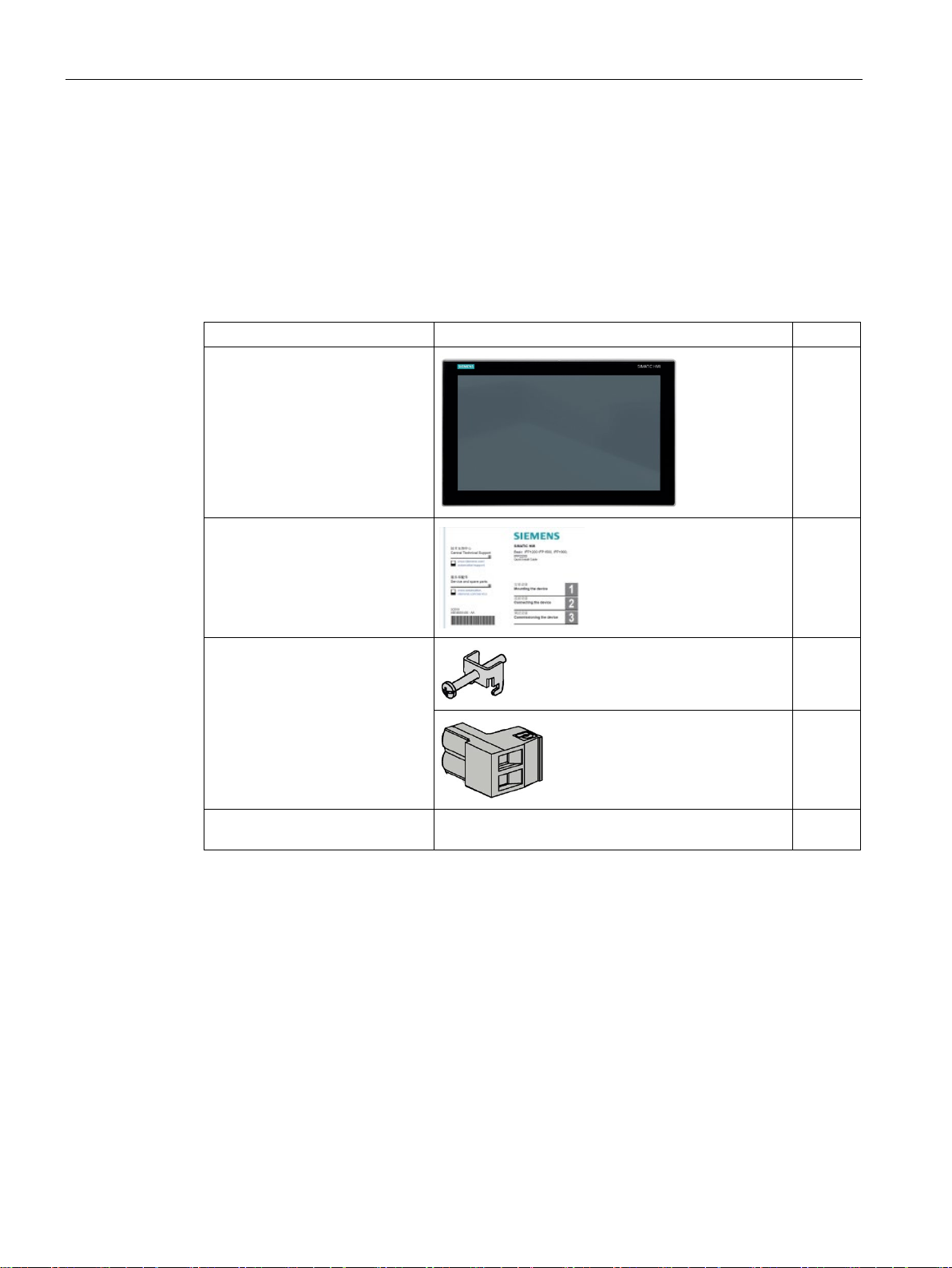
The product package includes the following components:
SIMATIC IFP Basic
Installation instructions
(Quick Install Guide)
Accessory kit
"Mounting clips
and
power supply connector"
"Tools, Drivers and Documenta-
1
1
20
1
1
IFP Basic
8 Operating Instructions, 03/2019, A5E46178354 - AB
Page 9
Overview
1.3
Exterior design
1.3.1
IFP Basic
Front view and side view
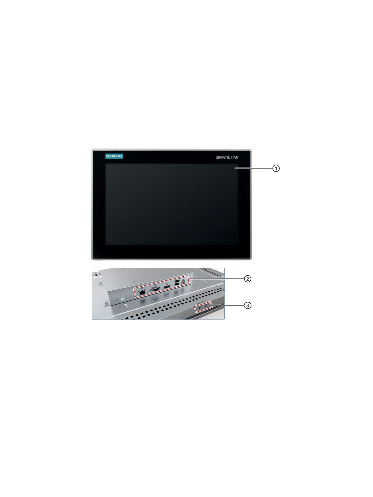
①
Display/touch screen
②
Interfaces
③
Recesses for mounting clips
1.3 Exterior design
This section describes the design of the monitor and touch devices, using the IFP1500 Basic
as an example.
IFP Basic
Operating Instructions, 03/2019, A5E46178354 - AB
9
Page 10
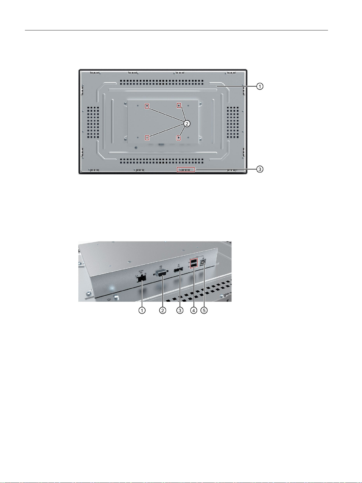
Overview
Rear view
①
Rating plate
②
Holes for VESA mounting
③
Recesses for mounting clips
1.3.2
Interfaces
①
X80 connector for 24 VDC power supply
②
X72 VGA interface
③
X71 DisplayPort interface
④
X61, X62 USB 2.0 Type A
⑤
X60 USB 2.0 Type B
1.3 Exterior design
IFP Basic
10 Operating Instructions, 03/2019, A5E46178354 - AB
Page 11

Overview
1.4
Accessories
Name
Specification
Article number
3 m long
6AV7860-0DH30-0AA0
3 m long
6AV7860-0CH30-0AA0
1.4 Accessories
This section contains the number of accessories available at the time of publication of the
operating instructions. You will find additional accessories on the Internet at: Industry Mall
(https://mall.industry.siemens.com/)
DisplayPort line
5 m long 6AV7860-0DH50-0AA0
USB line
5 m long 6AV7860-0CH50-0AA0
IFP Basic
Operating Instructions, 03/2019, A5E46178354 - AB
11
Page 12
2
2.1
General safety instructions
Machinery Directive
WARNING
The device may only be used in machines which comply with the Machinery Directive
Strong high-frequency radiation
NOTICE
Observe immunity to high-frequency radiation
The device is designed for use in the industrial sector for operating and monitoring plant
processes.
The Machinery Directive specifies precautions to be taken when commissioning and
operating machinery within the European Economic Area.
Failure to follow these precautions is a breach of the Machinery Directive. Such failure may
also cause personal injury and damage depending on the machine operated.
The machine in which the HMI device is to be operated must conform to Directive
2006/42/EC.
Observe the safety and accident prevention instructions applicable to your application in
addition to the safety information given in the device documentation.
The device has an increased immunity to high frequency radiation according to the
specifications on electromagnetic compatibility in the technical specifications.
Radiation exposure in excess of the specified immunity limits can impair device functions
and result in malfunctions and therefore injuries or damage.
Read the information on immunity to high frequency radiation in the technical specifications.
IFP Basic
12 Operating Instructions, 03/2019, A5E46178354 - AB
Page 13

Safety information
Additional notes for built-in units
NOTICE
The rear of the device constitutes open equipment.
protection against
Electrocution risk when control cabinet is open
ESD
Industrial Security
2.1 General safety instructions
The rear of the device constitutes open equipment. This means that the device may only be
installed in an enclosure or cabinet which provides front access for operating the device.
The enclosure, the cabinet or the electrical operating rooms must provide
electric shock and the spread of fire. The requirements regarding the mechanical strength
must also be taken into account.
Access to the enclosure or cabinet in which the device is installed should only be possible
by means of a key or tool and for trained and authorized personnel.
When you open the control cabinet, there may be a dangerous voltage at certain areas or
components.
If you touch these areas or components, you may be killed by electric shock.
Always disconnect the control cabinet from the mains before opening it. Do not plug in or
pull out the system component during operation.
An electrostatically sensitive device is equipped with electronic components. Due to their
design, electronic components are sensitive to overvoltage and thus to the discharge of
static electricity. Note the corresponding regulations when handling ESD.
Siemens provides products and solutions with industrial security functions that support the
secure operation of plants, systems, machines and networks.
In order to protect plants, systems, machines and networks against cyber threats, it is
necessary to implement – and continuously maintain – a holistic, state-of-the-art industrial
security concept. Siemens’ products and solutions constitute one element of such a concept.
Customers are responsible for preventing unauthorized access to their plants, systems,
machines and networks. Such systems, machines and components should only be
connected to an enterprise network or the internet if and to the extent such a connection is
necessary and only when appropriate security measures (e.g. use of firewalls and network
segmentation) are in place.
For additional information on industrial security measures that may be implemented,please
visit (http://www.siemens.com/industrialsecurity).
Siemens’ products and solutions undergo continuous development to make them more
secure. Siemens strongly recommends that product updates are applied as soon as they are
available and that the latest product versions are used. Use of product versions that are no
longer supported, and failure to apply latest updates may increase customer’s exposure to
IFP Basic
Operating Instructions, 03/2019, A5E46178354 - AB
cyber threats.
13
Page 14

Safety information
Disclaimer for third-party software updates
Notes on protecting administrator accounts
2.2
Data protection
2.3
Notes about usage
Note
Operate the device only in a normal atmospheric environment
The technical characteristics of the device described in the operating instructions are
guaranteed if you operate the device in norma
composition.
2.2 Data protection
To stay informed about product updates, subscribe to the Siemens Industrial Security RSS
Feed under (http://www.siemens.com/industrialsecurity).
This product includes third-party software. Siemens AG only provides a warranty for
updates/patches of the third-party software, if these have been distributed as part of a
Siemens software update service contract or officially released by Siemens AG. Otherwise,
updates/patches are undertaken at your own risk. You can find more information about our
Software Update Service offer on the Internet at Software Update Service
((http://www.automation.siemens.com/mcms/automation-software/en/software-update-
service).
A user with administrator privileges has extensive access and manipulation options in the
system.
Therefore, ensure there are adequate safeguards for protecting the administrator accounts
to prevent unauthorized changes. To do this, use secure passwords and a standard user
account for normal operation. Other measures, such as the use of security policies, should
be applied as needed.
Siemens observes the data protection guidelines, especially the requirements regarding data
minimization (privacy by design). This means the following for this SIMATIC product: The
product does not process / save any personal information, but only technical functional data
(e.g. time stamps). If the user links this data to other data (e.g. shift plans) or if the user
saves personal information on the same medium (e.g. hard disk) and therefore creates a
personal reference in the process, the user has to ensure meeting the guidelines regarding
data protection.
l ambient air conditions with usual air
IFP Basic
14 Operating Instructions, 03/2019, A5E46178354 - AB
Page 15

Safety information
Industrial applications
Use in mixed-use zone
Use in residential areas
Note
IFP Basic is not intended for use in residential area
The device is not intended for use in residential areas. Operation of a device in residential
areas can have a negative influence on radio or TV reception.
Use with additional measures
Reducing vibrations
2.3 Notes about usage
The device is designed for industrial applications. It conforms to the following standards:
● Requirements for emissions EN 61000-6-4: 2007
● Requirements for interference immunity EN 61000-6-2: 2005
Under certain circumstances you can use the device in a mixed-use zone. A mixed-use zone
is used for housing and commercial operations that do not have a significant impact on
residents.
When you use the device in a mixed-use zone, you must ensure that the limits of the generic
standard EN 61000-6-3 regarding emission of radio frequency interference are observed.
Suitable measures for achieving these limits for use in a mixed-use zone include:
● Installation of the device in grounded control cabinets
● Use of filters in electrical supply lines
Individual acceptance is required.
The device should not be used at the following locations unless additional measures are
taken:
In locations with a high degree of ionizing radiation
● In locations with severe operating conditions, for example, due to:
– Corrosive vapors, gases, oils or chemicals
– Strong electrical or magnetic fields of high intensity
● In systems that require special monitoring, for example, in:
– Elevators
– Systems in especially hazardous rooms
If the device is subjected to greater shocks or vibrations, you must take appropriate
measures to reduce acceleration or amplitudes.
We recommend mounting the device on damping materials, such as rubber-metal vibration
dampers.
IFP Basic
Operating Instructions, 03/2019, A5E46178354 - AB
15
Page 16

Safety information
Risk analysis and measures
WARNING
Hazards emanating from unprotected machines or plants
Environment
NOTICE
Ambient conditions and chemical resistance
2.3 Notes about usage
The results of a risk analysis can reveal any hazards emanating from unprotected
machinery. Such hazards may pose a risk of personal injury.
You can prevent personal injury caused by hazards as specified in the risk analysis by
taking the following measures:
• Installing additional protective devices on machinery and plants. In particular, it must
also be ensured that the programming, configuration and wiring of all I/Os used takes
place in accordance with the safety performance (SIL, PL or Cat.) identified by the
requisite risk analysis.
• Use of the device in accordance with its intended purpose, which can be verified by
means of a system function test. This test can detect programming, configuration and
wiring errors.
• Documentation of the test results, which must be entered in the relevant safety reports if
required.
Ambient conditions not suited for the device can adversely affect operation. Chemical
agents, such as detergents or operating material, can change the color, shape and
structure of the device surface. The device may be damaged. This may lead to
malfunctions.
For this reason, the following precautionary measures should be taken:
• Only operate the device in closed rooms. Failure to comply with these instructions will
render the warranty null and void.
• Only operate the device in the ambient conditions specified in the technical
specifications.
• Protect the device against dust, moisture and heat.
• The device may not be used in harsh operating environments, such as areas subject to
acidic vapors or gases, without additional protective measures (for example. a clean air
supply).
• Only use suitable detergents. Read the information about Chemical resistance of the
devices and industrial PCsChemical resistance of the HMI devices and industrial PCs
(http://support.automation.siemens.com/WW/view/en/39718396) on the Internet.
IFP Basic
16 Operating Instructions, 03/2019, A5E46178354 - AB
Page 17

Safety information
See also
2.3 Notes about usage
Operating conditions (Page 61)
Technical specifications (Page 58)
IFP Basic
Operating Instructions, 03/2019, A5E46178354 - AB
17
Page 18

3
3.1
Preparing for installation
3.1.1
Checking the delivery package
Procedure
Note
Damage to the device during transport and storage
If a device is transported or stored without packaging, shocks, vibrati
moisture may impact the unprotected unit. Damaged packaging indicates that ambient
conditions have already had a massive impact on the device and it may be damaged.
This may cause the device, machine or plant to malfunction.
•
•
1. When accepting a delivery, please check the packaging for visible transport damage.
2. If any transport damage is present at the time of delivery, lodge a complaint at the
shipping company in charge. Have the shipper confirm the transport damage
immediately.
3. Unpack the device at its installation location.
4. Keep the original packaging in case you have to transport the unit again.
ons, pressure and
Keep the original packaging.
Pack the device in the original packaging for transportation and storage.
5. Check the contents of the packaging and any accessories you may have ordered for
completeness and damage.
IFP Basic
18 Operating Instructions, 03/2019, A5E46178354 - AB
Page 19

Installing and connecting the device
WARNING
Electric shock and fire hazard due to damaged device
NOTICE
Damage from condensation
3.1 Preparing for installation
6. Please inform the delivery service immediately if the package contents are incomplete or
damaged or do not correspond with your order.
A damaged device can be under hazardous voltage and trigger a fire in the machine or
plant. A damaged device has unpredictable properties and states.
Death or serious injury could occur.
Make sure that the damaged device is not inadvertently installed and put into operation.
Label the damaged device and keep it locked away. Send off the device for immediate
repair.
If the device is subjected to low temperatures or extreme fluctuations in temperature
during transportation, as is the case in cold weather, for example, moisture can build up
on or inside the device (condensation).
Moisture causes a short circuit in electrical circuits and damages the device.
In order to prevent damage to the device, proceed as follows:
• Store the device in a dry place.
• Bring the device to room temperature before starting it up.
• Do not expose the device to direct heat radiation from a heating device.
• If condensation develops, wait until the device is completely dry before switching it
on.
7. Keep the enclosed documentation in a safe place. You need the documentation when
you commission the device for the first time.
8. Write down the identification data of the device.
IFP Basic
Operating Instructions, 03/2019, A5E46178354 - AB
19
Page 20
Installing and connecting the device
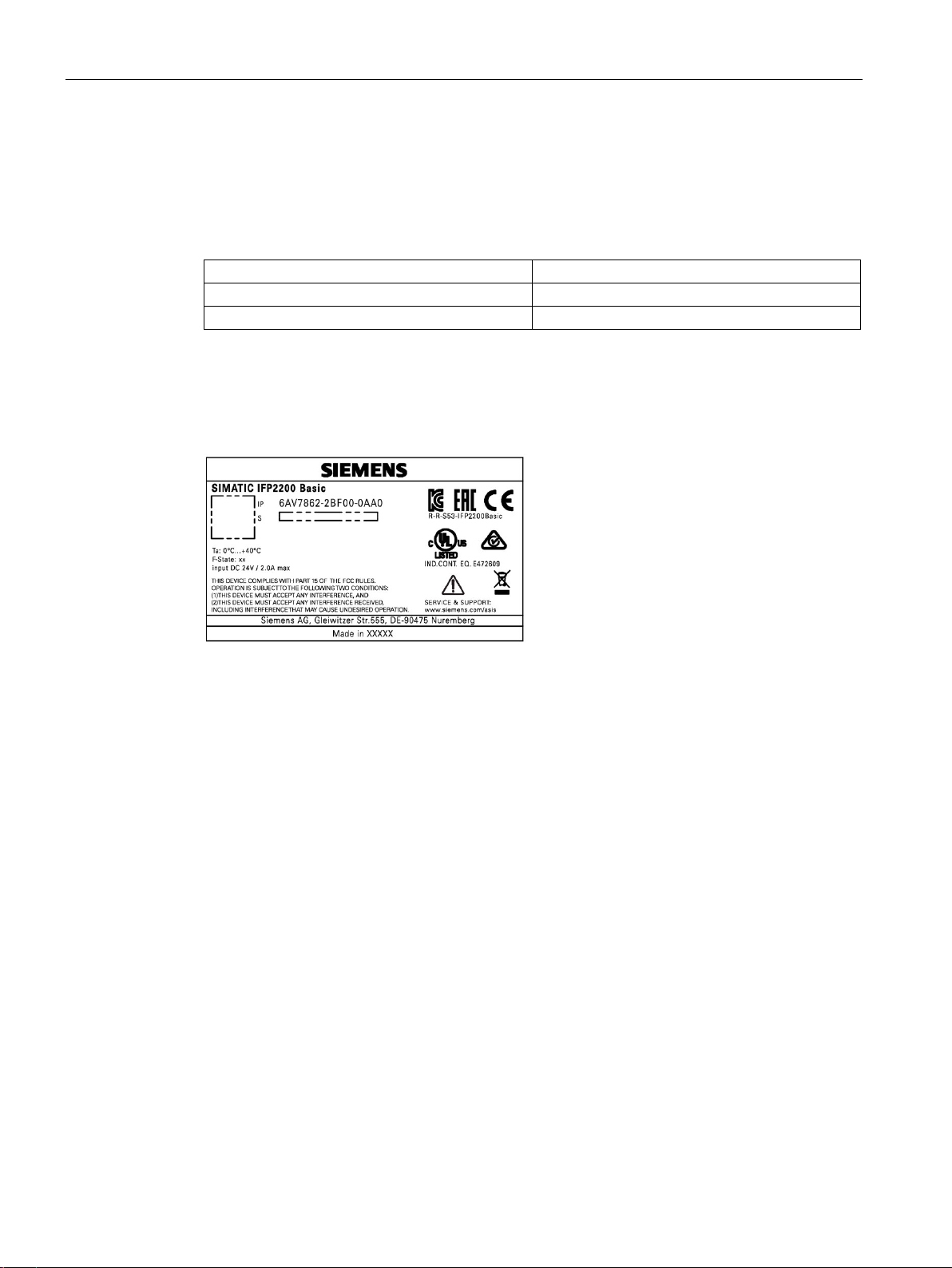
3.1.2
Identification data of the device
Order number
6AV...
Serial number
S V
Procedure
3.1 Preparing for installation
The device can be clearly identified with the help of this identification data in case of repairs
or theft.
Enter the identification data in the following table:
Product version FS
Get the information of order number, serial number, and production version (FS) from the
product label. Below is an example of a product label.
IFP Basic
20 Operating Instructions, 03/2019, A5E46178354 - AB
Page 21

Installing and connecting the device
3.1.3
Permitted mounting positions
Maximum ambient temperature at the
device
Comment
40 °C (IFP2200 Basic)
3.1 Preparing for installation
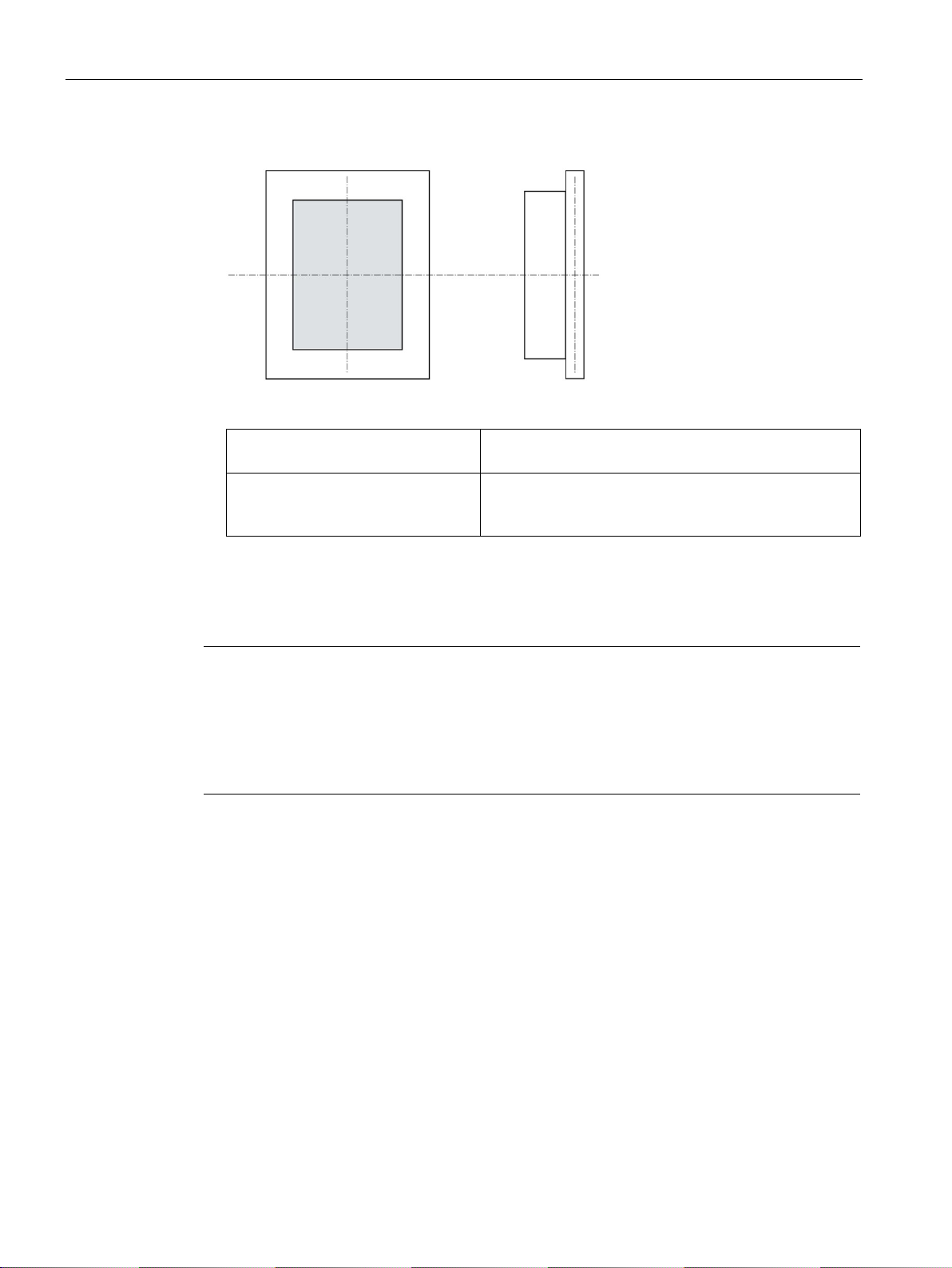
The device may be mounted in the following positions:
● Standard position: horizontal
● Inclined installation in horizontal format with a vertical inclination of maximum ±45 °
For horizontal installation, the following ambient temperatures are permitted:
45 °C (IFP1200 Basic, IFP1500
Basic, IFP1900 Basic)
The device enclosure fulfills the requirement of a fire
protection enclosure.
IFP Basic
Operating Instructions, 03/2019, A5E46178354 - AB
21
Page 22
Installing and connecting the device
Maximum ambient temperature at the
device
Comment
40 °C (IFP2200 Basic)
3.1.4
Preparing the mounting cutout
Note
Stability of the mounting cutout
The material in the area of the mounting cutout must provide sufficient strength to guarantee
the enduring and safe mounting of the device.
To achieve the degrees of protection described below, it must be ensured that deformation
of the material cannot occur due to the force of the mounting clips or operation of the device.
Degrees of protection
3.1 Preparing for installation
● Vertical installation: display turned through ±90 ° compared with the standard position
For vertical installation, the following ambient temperatures are permitted:
The degrees of protection of the device can only be guaranteed if the following requirements
are met:
● In order to achieve IP65 protection degree, the material thickness for the mounting cutout
should be: 2 mm to 6 mm
45 °C (IFP1200 Basic, IFP1500
Basic, IFP1900 Basic)
The device must be installed in a fire protection enclosure
(see "General safety instructions (Page 12)").
● Permissible deviation from plane at the mounting cutout: ≤ 0.5 mm
This condition must be fulfilled for the mounted device.
● Permissible surface roughness in the area of the seal: ≤ 120 µm (R
IFP Basic
22 Operating Instructions, 03/2019, A5E46178354 - AB
120)
z
Page 23
Installing and connecting the device
Dimensions of the mounting cutout
Mounting cutout
Device
12 Inch
15 Inch
19 Inch
22 Inch
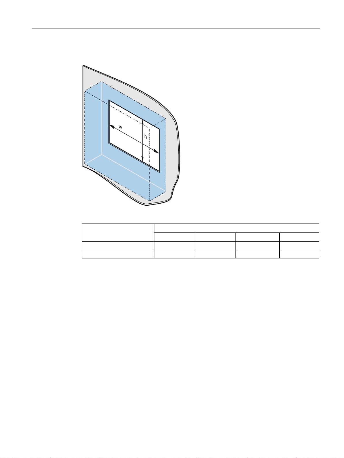
Width w *
302+1 mm
388.4+1 mm
455+1 mm
522.2+1 mm
Height h *
208+1 mm
240.5+1 mm
279.2+1 mm
316.8+1 mm
*
Width and height should be reversed accordingly when mounting in vertical format.
3.1 Preparing for installation
The following table shows the dimensions of the required mounting cutout:
IFP Basic
Operating Instructions, 03/2019, A5E46178354 - AB
23
Page 24
Installing and connecting the device
3.1.5
Checking clearances
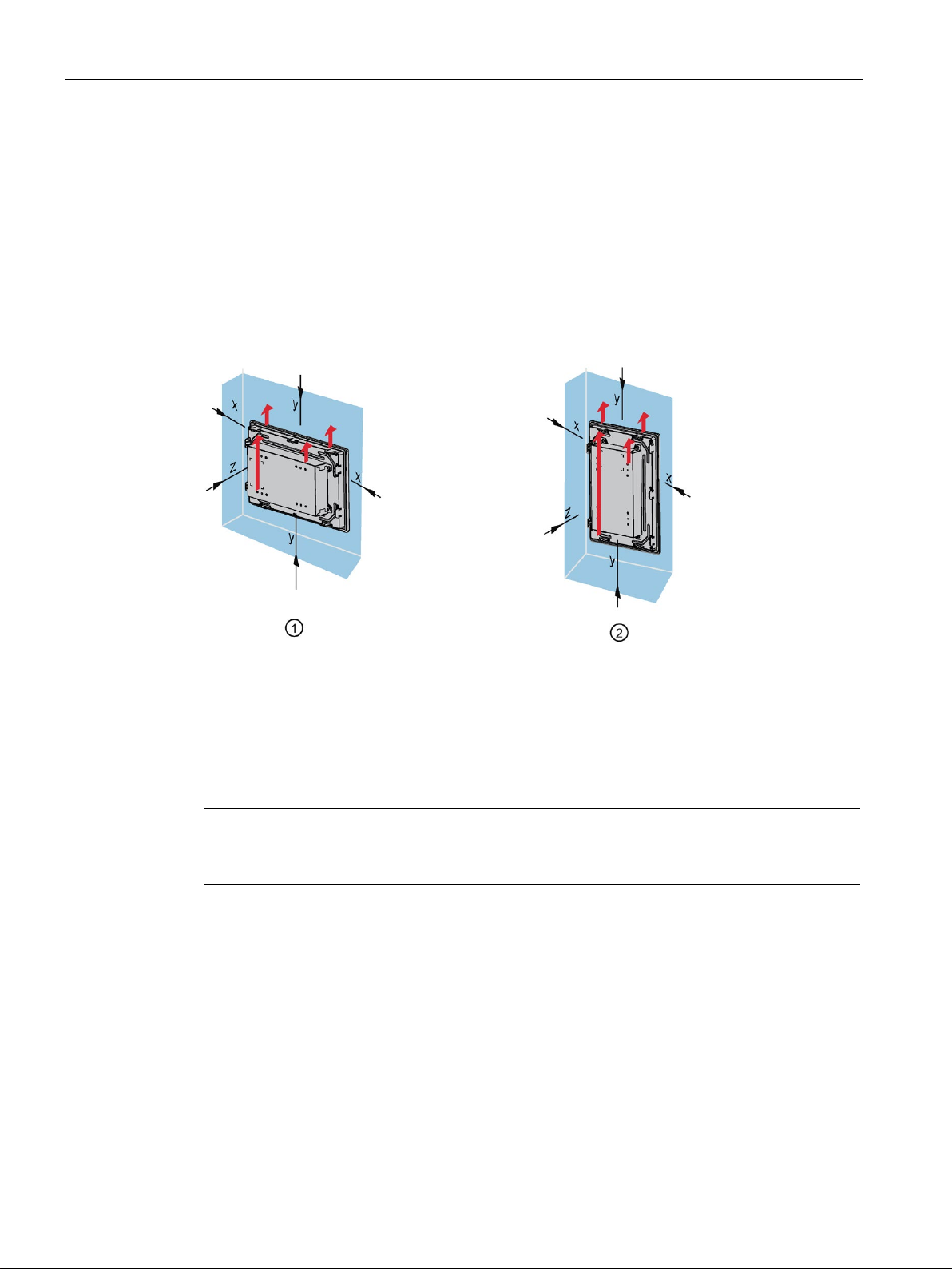
①
Clearance for horizontal installation (all devices)
②
Clearance for vertical installation (monitor and touch versions only)
x
At least 50 mm distance
y
At least 50 mm distance
z
At least 10 mm distance
Note
Ensure that the maximum ambient temperature is not exceeded when mounting the device
in a cabinet and especially in a closed enclosure.
3.1 Preparing for installation
The following clearances are required around the device to ensure adequate self-ventilation:
● At least 50 mm to the right and left of the mounting cutout (in x direction) to allow for
insertion of the mounting clips during installation
● At least 50 mm above and below the mounting cutout (in y direction) for ventilation
● At least 10 mm behind the rear panel of the device (in z direction)
The figure below shows the clearances required with horizontal and vertical installation of the
device:
IFP Basic
24 Operating Instructions, 03/2019, A5E46178354 - AB
Page 25
Installing and connecting the device
3.2
Installing the IFP Basic
3.2.1
Notes on installation
WARNING
Risk of fire
Note
If the equipment is used in an manner not specified by the manufacture, the protection
provided by the equipment might be impaired.
3.2 Installing the IFP Basic
Before installing the device, please ensure that the installation location complies with the
following:
The device is classified as "OPEN EQUIPMENT" for use in the area of industrial control
equipment in accordance with UL61010-2-201. In the event of overheating, the device may
discharge burning materials that can cause a fire.
Keep in mind:
• The installation of the device in an enclosure conforming to UL61010-2-201 is a
mandatory requirement for approval and operation in accordance with UL61010-2-201.
● Ensure that the protective contact socket of the building installation is easily accessible
and that there is a mains disconnect switch in switchgear cabinet installations.
● Position the device so that it is not exposed to direct sunlight.
● Position the device so that it is easily accessible for the operator.
● Choose a suitable installation height.
● Ensure that the air vents of the device are not covered as a result of installation. Note the
permitted mounting positions.
IFP Basic
Operating Instructions, 03/2019, A5E46178354 - AB
25
Page 26
Installing and connecting the device
3.2.2
Secure with mounting clips
Positions of the mounting clips
Device
Mounting clips
Type
Quan-
tity
Position on the device
3.2 Installing the IFP Basic
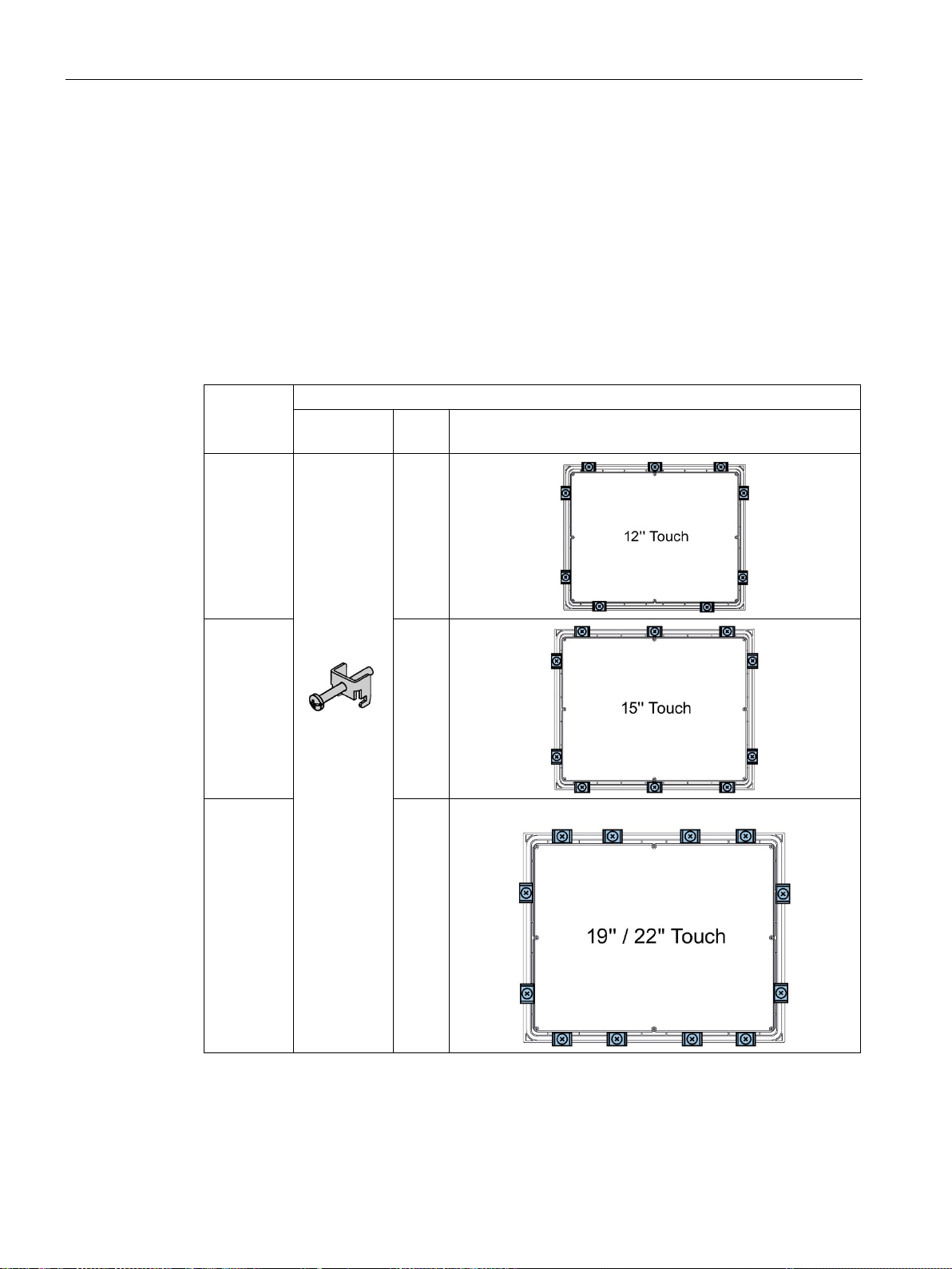
To achieve the degree of protection for the device, the positions for the mounting clips
shown below must be adhered to.
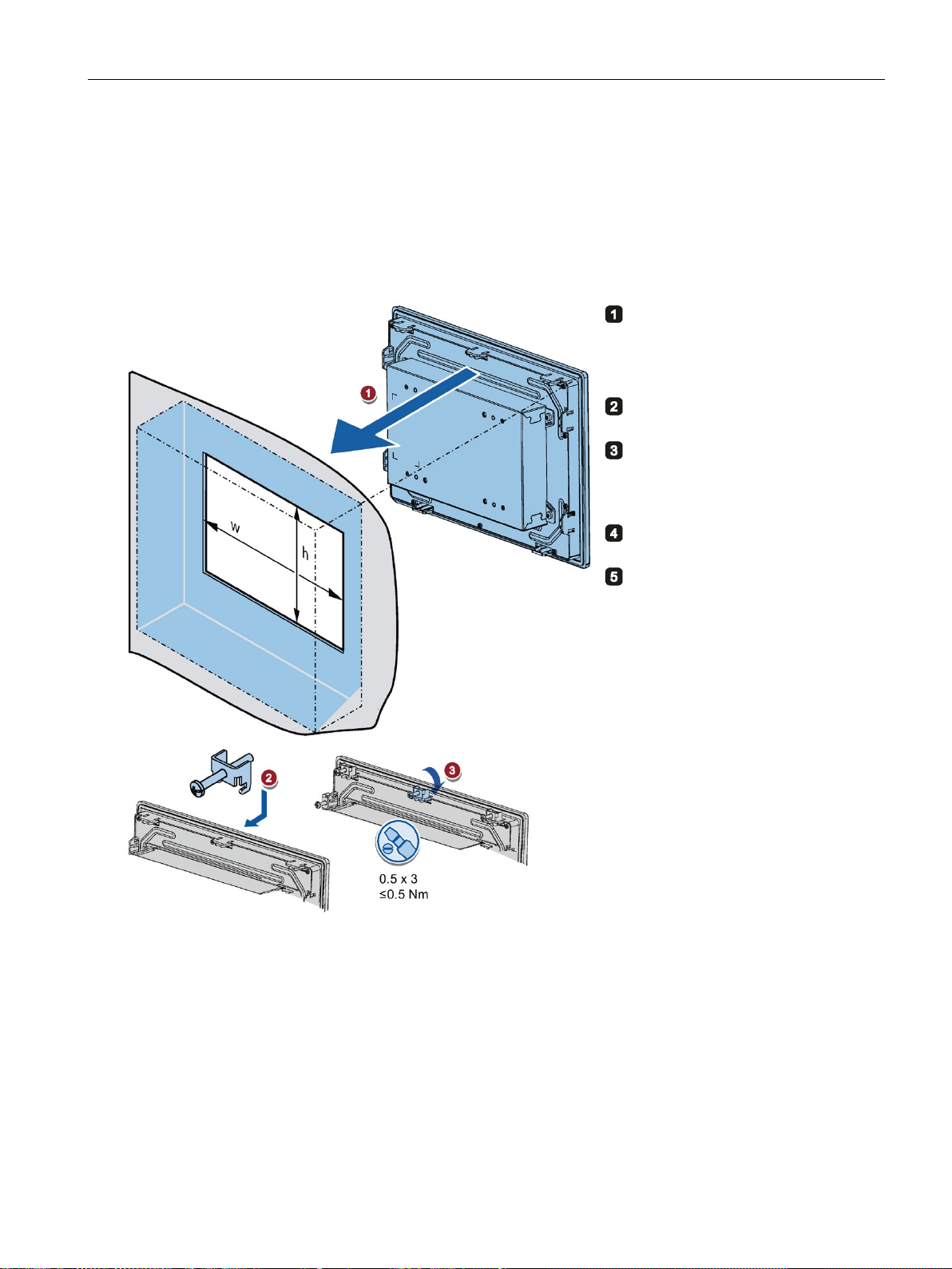
The positions of the mounting clips are marked by stamps on the cutouts. Fit the mounting
clips in all the stamped cutouts.
The following table shows the type, number, and position of the mounting clips needed for
the respective devices.
12" display
15" display 10
19" display
22" display
9
12
IFP Basic
26 Operating Instructions, 03/2019, A5E46178354 - AB
Page 27
Installing and connecting the device
Requirement
Procedure
Insert the panel device into the
mounting cutout from the front.
Insert a mounting clip into the
cutout provided on the device.
Tighten the threaded pin to secure
the mounting clip. The threaded
pins have a maximum tightening
torque of 0.5 Nm.
Repeat steps 2 and 3 for all
mounting clips.
Check the fit of the mounting seal.
Result
3.2 Installing the IFP Basic
● All packaging components and protective films should be removed from the device.
● To install the panel, you need the mounting clips from the accessories kit.
The device is mounted and the relevant degree of protection is ensured at the front.
IFP Basic
Operating Instructions, 03/2019, A5E46178354 - AB
27
Page 28
Installing and connecting the device
3.2.3
Fastening a device using a VESA adapter
Note
To meet UL requirements, the type of VE
When fastening the VESA adapter, shock or vibration is not permitted.
NOTICE
Degree of protection for overall device
NOTICE
Dimensioning of the VESA adapter
WARNING
The device must be mounted securely
3.2 Installing the IFP Basic
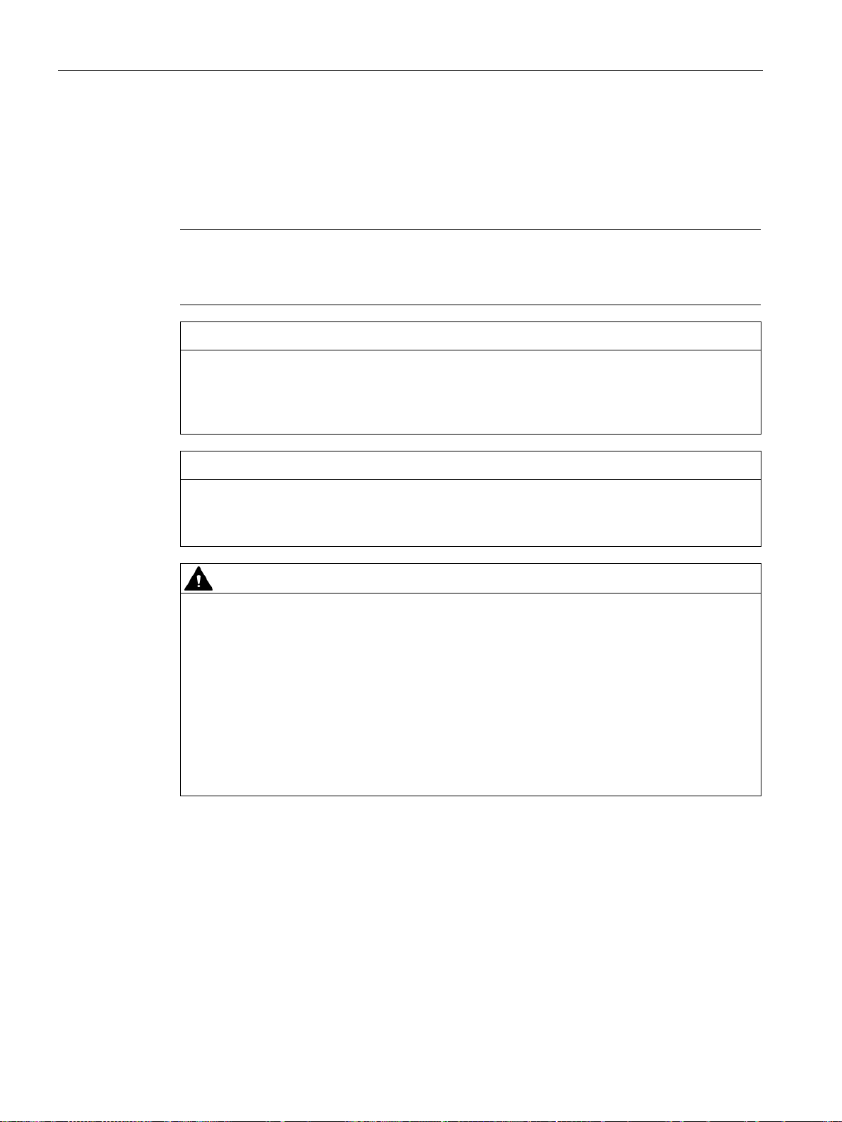
You can also fasten the SIMATIC IFP Basic using a VESA (Video Electronics Standards
Association) adapter.
Different models of VESA adapters are offered by third-party manufacturers.
SA adapter must be an UL1678 listed device.
If you are fastening the device via a VESA adapter, degree of protection of the device will
be lost. Spray and water jets as well as penetrating substances can then damage the
device.
When selecting the VESA adapter, make sure that it is designed for at least four times the
weight of the device.
Inadequately dimensioned fastening material may cause the device to fall down. Serious
bodily injury may result.
Make sure that fasteners are adequately dimensioned during installation of the device.
Make sure to consider the weight of the device and the forces acting on the device when
dimensioning the fasteners. This applies in particular to dynamic load of the device. All
fasteners including mounting surfaces, support arm systems, and fastening elements such
as screws must be able to carry at least four times the weight of the device.
Observe any further statutory specifications applying at the location of use of the device
and further applicable regulations with regard to the fastening of the device.
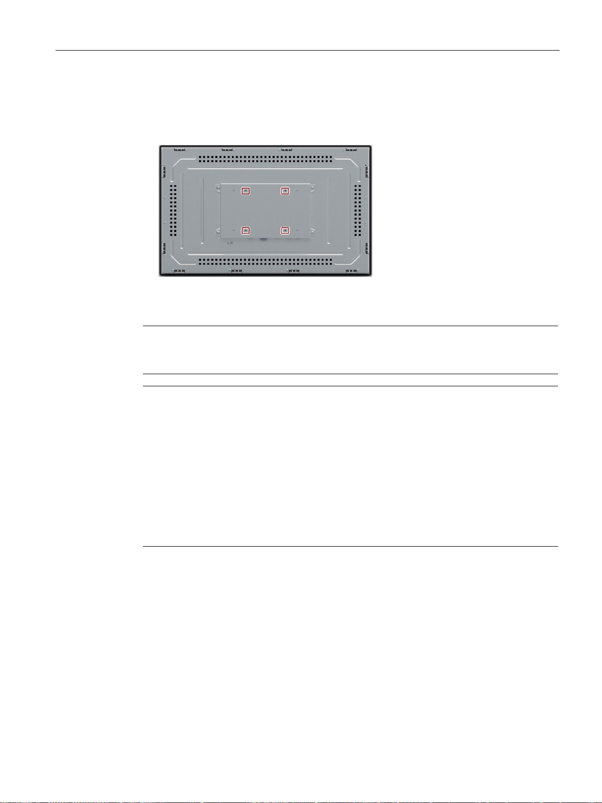
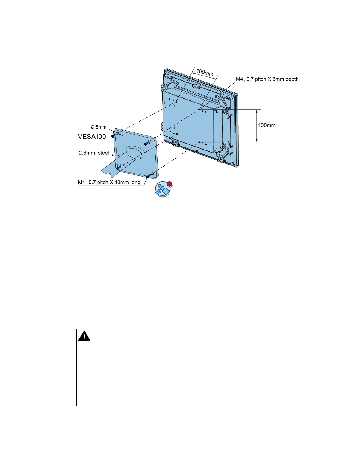
SIMATIC IFP Basic is VESA compliant and can be mounted on all kinds of applications
utilizing the standard VESA100 mounting interfaces.
Fasten the VESA adapter with the designated screws (M4).
IFP Basic
28 Operating Instructions, 03/2019, A5E46178354 - AB
Page 29
Installing and connecting the device
Requirements
Procedure
Note
Make sure your support application is VESA100 compliant. Otherwise, you cannot use it to
support the IFP Basic.
Note
Observe the torques
If you use too much
support arm or stand, the support arm may be damaged. If you tighten the screws with a
torque that is too low
Tighten the screws with the following torques
Adhere to the torque specifications of the third
Siemens recommends you use 1.5 Nm tightening torque to connect the device and the
VESA mounting interface
VESA adapter does not influent heat dissipation.
3.2 Installing the IFP Basic
● All packaging components and protective films have been removed.
● VESA support application (for example, an arm or a stand) from a third party
torque to tighten the screws of the screws for fastening the device to a
, the device is not sealed.
, which may not be exceeded.
-party vendors:
IFP Basic
Operating Instructions, 03/2019, A5E46178354 - AB
29
Page 30
Installing and connecting the device
3.3
Connecting the device
3.3.1
Notes on connection
Requirement
Connecting cables
CAUTION
Use copper cables at connectors with terminal connections
Utiliser des câbles en cuivre sur les connexions à bornes
3.3 Connecting the device
Secure the device to the mounting interface with four M4 x 10 screws.
● The device has been installed according to the information provided in these operating
instructions.
Use copper (Cu) cables for all supply lines that are connected to the device with terminals,
e.g. 24 VDC power supply cables to the 24 VDC power supply connectors.
Utilisez des câbles en cuivre (Cu) pour tous les câbles d'alimentation qui sont raccordés à
l'appareil par des bornes, par exemple les câbles d'alimentation 24 V CC sur le connecteur
d'alimentation 24 V CC.
IFP Basic
30 Operating Instructions, 03/2019, A5E46178354 - AB
Page 31
Installing and connecting the device
Connection sequence
WARNING
Life-threatening voltages are present if the device not correctly isolated.
Note
Damage to the device
Failure to adhere to the connection sequence can damage the device.
Make sure you connect the device according to sequence listed above.
Connecting the cables
NOTICE
Observe local installation regulations
Short-circuit and overload protection
3.3 Connecting the device
Connect the device in the following sequence:
1. Earth connection (Page 32)
If you touch the device, you may be killed by electric shock.
Do connect the PE conductor before you power on the device.
2. Power supply (Page 33)
Perform a power-up test to ensure the power supply is connected with the correct
polarity.
3. Connecting IFP Basic to a PC (Page 35)
4. I/O devices (Page 36), if needed
You disconnect the device in the reverse order.
Observe the local installation guidelines and the local installation conditions, such as
protective wiring for power supply cables, when connecting the cables.
Different measures for short-circuit and overload protection are required when setting up an
entire plant. The type of components and the level of obligation for the protective measures
depends on the regulation that applies to your plant configuration.
● When connecting the cables, make sure that you do not bend the contact pins.
● Secure each cable connector with a cable tie.
● Provide adequate strain relief for all cables.
● The pin assignment of the ports is described in the technical specifications.
IFP Basic
Operating Instructions, 03/2019, A5E46178354 - AB
31
Page 32
Installing and connecting the device
3.3.2
Earthing the device
Requirement
Procedure
1.
2.
3.
3.3 Connecting the device
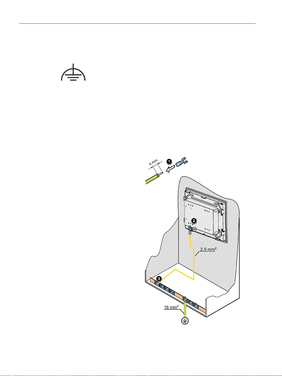
The relevant symbol on the device identifies the terminal for the earth connection.
● T20 screwdriver
● Cable lug for M4
● Protective conductor or equipotential-bonding cable with minimum cross-section 2.5 mm
2
The figure below shows the connection of a function earth.
Clamp the cable lug onto the
ground cable:
– PE conductor: yellow-
green, as depicted.
– Equipotential bonding:
black
Using the M4 screw, firmly
attach the cable lug to the
earth connection on the
device with a torque of
0.8 Nm.
Connect the function earth to
the earth connection of the
cabinet or plant in which the
device is installed.
IFP Basic
32 Operating Instructions, 03/2019, A5E46178354 - AB
Page 33
Installing and connecting the device
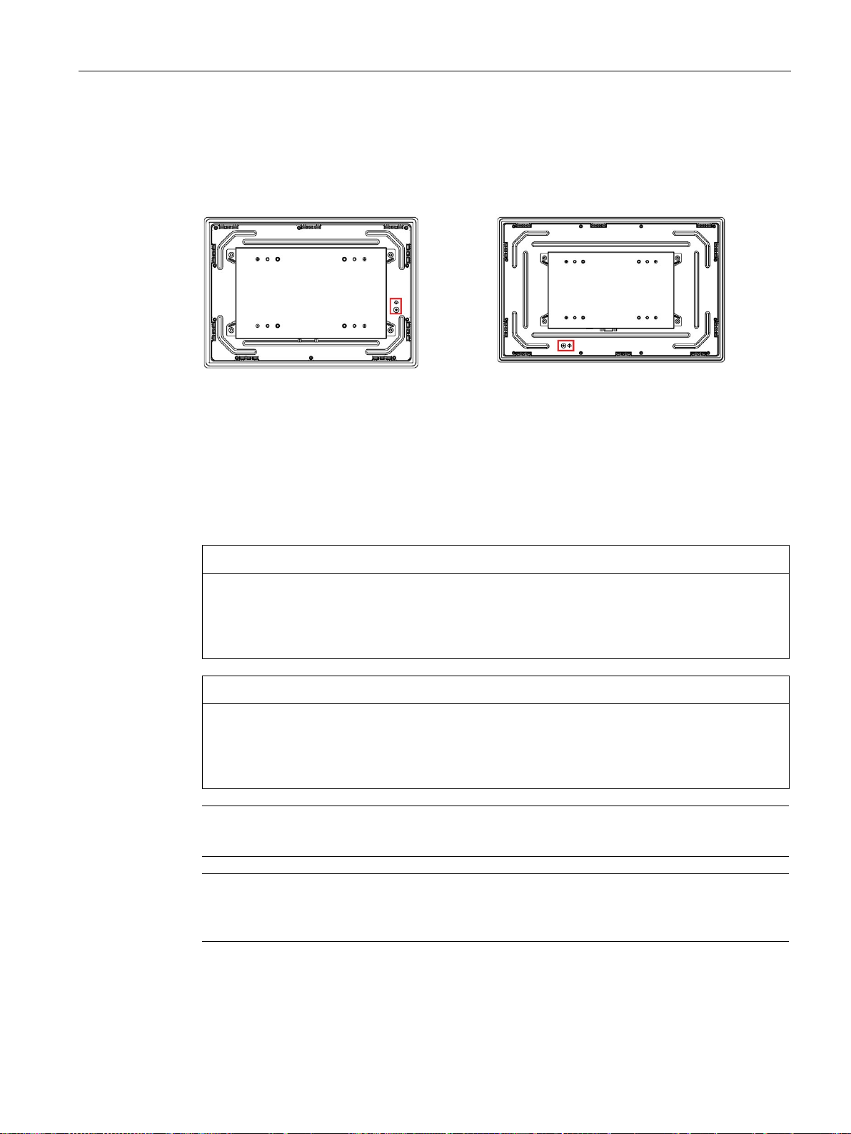
Location of function earth
SIMATIC IFP1200 Basic
SIMATIC IFP1500/1900/2200 Basic
3.3.3
Connecting devices with 24 VDC 2-pin
Note before connecting the device
NOTICE
Safe electrical isolation
NOTICE
Damage to device due to inadequate cable cross-section
Note
Siemens recommends you use 5 lb
Note
The 24 VDC power supply must be adapted to the input data of the device, see section
"
3.3 Connecting the device
The location of function earth for SIMATIC IFP1200 Basic is different from other IFP Basic.
You can operate the IFP Basic with the voltage 24 VDC 2-pin.
The device may only be connected to a 24 VDC power supply that meets the requirements
of a safe extra-low voltage (SELV) according to IEC/EN/DIN EN/UL 61010-1 or the
requirements of a secure extra-low voltage (SELV/PELV) according to IEC 61010-1.
Using power supply cables with cross-sections that are too small can damage the device in
the event of a short circuit. The power supply connector is designed for cables with a crosssection between 0.75 mm
2
and 2.5 mm2.
-in (0.56Nm) to fasten the power supply cable.
Technical specifications (Page 58)".
IFP Basic
Operating Instructions, 03/2019, A5E46178354 - AB
33
Page 34
Installing and connecting the device
Note
To turn off the device completely, switch off the external power supply. The device does not
have an on/off switch.
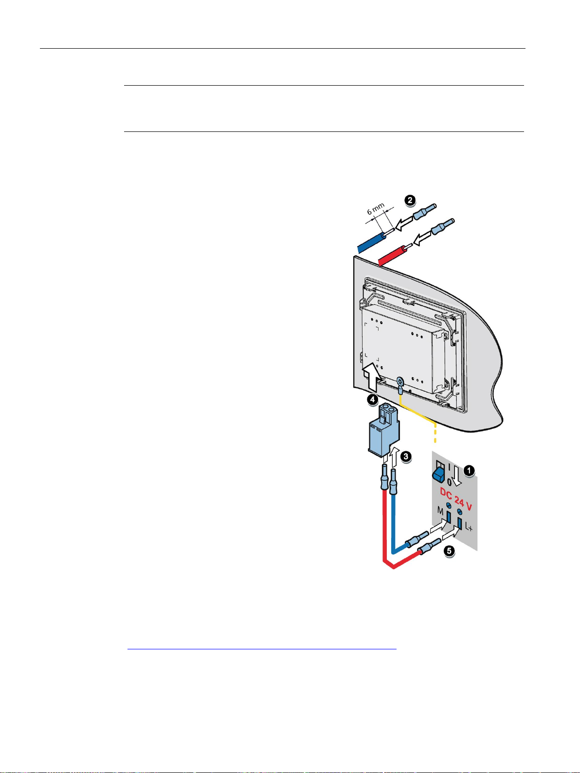
Procedure
1.
2.
3.
4.
5.
See also
3.3 Connecting the device
Switch off the 24 VDC power supply.
Ensure that the cable ends of the power
supply lines are fitted with end sleeves.
Fasten the end of a connecting cable L+ and
a connecting cable M with the supplied
power supply connector.
Connect the power supply connector to the
relevant terminal on the device.
Connect the remaining L+ and M ends with
the respective terminals on the 24 VDC
power supply.
Designing interference-free controllers Designing interference-free controllers
(https://support.industry.siemens.com/cs/ww/en/view/59193566)
IFP Basic
34 Operating Instructions, 03/2019, A5E46178354 - AB
Page 35
Installing and connecting the device
3.3.4
Connecting IFP Basic to a PC
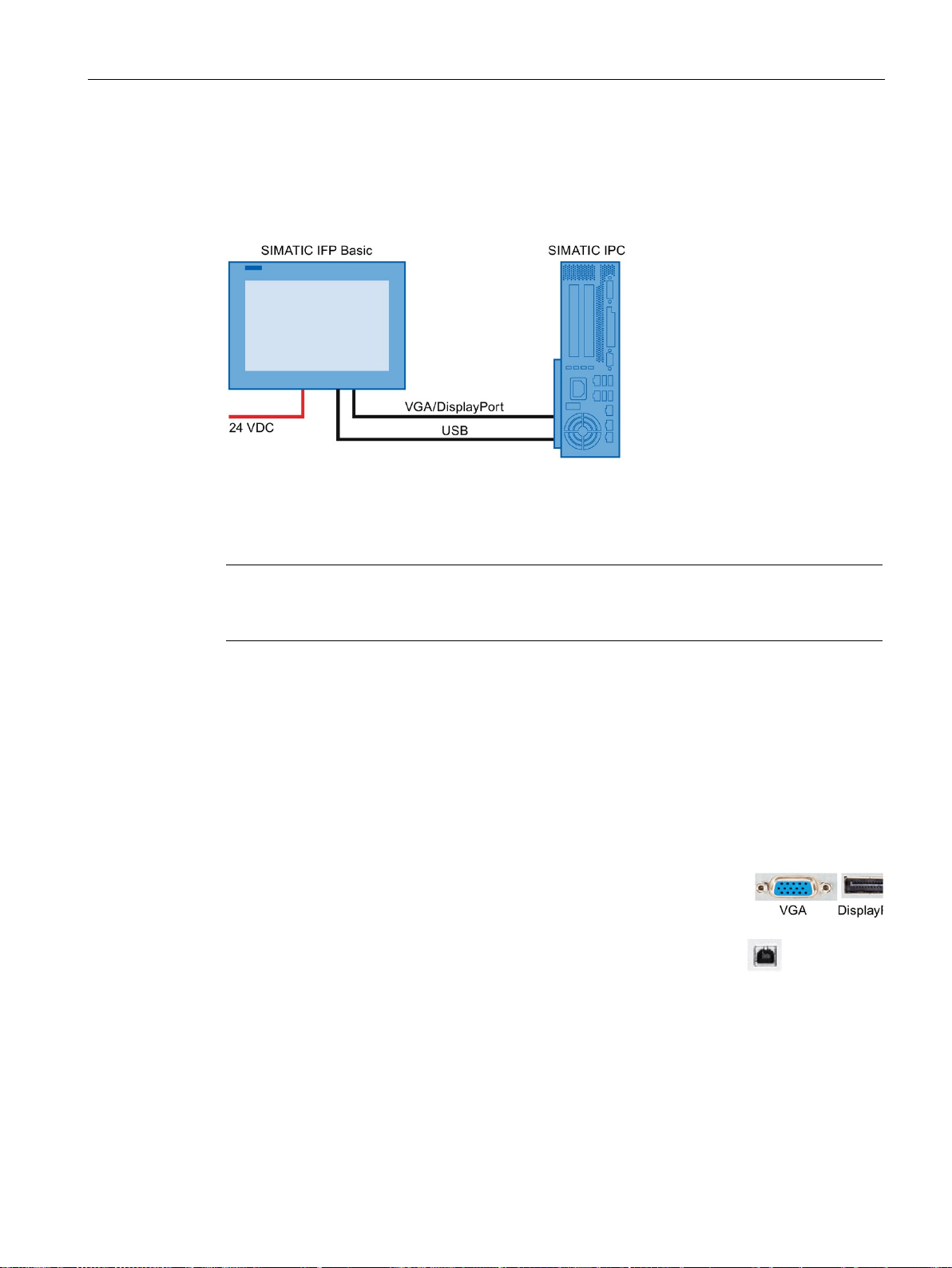
Connection diagram
Requirement
Note
When VGA port and DP port are connected to two hosts, IFP displays the signals from DP
port.
Procedure
1. Connect the Flat Panel and the PC using a VGA or DisplayPort
line.
2. Connect the device and the PC with a USB line (type A to type B).
3.3 Connecting the device
Ensure you have the following articles before connecting the IFP Basic.
● VGA/DisplayPort cable
● USB cable (type B to type A)
● Power cable
● PC
IFP Basic
Operating Instructions, 03/2019, A5E46178354 - AB
35
Page 36

Installing and connecting the device
3.3.5
Connecting a USB device
Note when connecting
Note
Use of USB devices
•
•
•
offers support for the I/O devices. Moreover, the terms of liability of the individual vendors
Note
Functional problem with USB port
If you connect an external device with a 230 VAC power supply to the USB port without
using a non
Excessive rated load on port
A USB device with too high a power load may possibly cause functional problems.
Observe the values for the maximum load of the USB interface. You will find the values in
the section "
3.4
Installing the tool and driver
Requirements
3.4 Installing the tool and driver
You can connect the following industry-standard devices to the USB ports of the device:
● External mouse
● External keyboard
● USB flash drive
Wait at least ten seconds between removal and reconnection of USB devices.
When using standard USB peripherals, bear in mind that their EMC immunity level is
frequently designed for office applications only. These devices may be used for
commissioning and servicing. However, only industry-standard devices are allowed for
industrial operation.
Peripherals are developed and marketed by individual vendors. The respective supplier
or suppliers apply here.
-insulated installation, you may experience functional problems.
Technical specifications" (Page 58)".
● Windows 7/Windows Embedded Standard 7, Windows 10 Operating System is installed
in your IPC.
● You need to connect your IFP to a PC with Windows 7/Windows Embedded Standard 7,
Windows 10 Operating System installed.
IFP Basic
36 Operating Instructions, 03/2019, A5E46178354 - AB
● Embedded or external DVD drive.
Page 37

Installing and connecting the device
Tool and driver list
To open the list
My Computer
Documentation and Drivers
index.htm
Driver and Tool
Alternative way to access the drivers
Step 1: install Brightness Adjustment Tool
Brightness Adjustment Tool
Next
Install
Finish
Prerequisites for installing the touch driver
3.4 Installing the tool and driver
The tool and driver need to be installed on the PC:
● Brightness Adjustment Tool
● Touch Driver
1. Put the
2. Double-click
3. Double-click
4. Click
The available driver list opened.
You can also find the drivers in the DRIVER folder of the
Below is an example path.
E:\DRIVER
Documentation and Drivers
.
to open the driver list.
1. Click
2. Click
3. Click
4. Click
5. Click
to install the Tool.
to continue.
to allow the computer to start the installation.
The installation starts.
.
DVD into the DVD drive.
→
.
to open the DVD.
Documentation and Drivers
DVD.
The Brightness Adjustment Tool installation is completed.
● Make sure you connect the IFP basic to the computer with touch cable before your
installing the driver.
● If you use Windows Embedded standard 7 or Windows 7, make sure you have the
Windows patch KB3033929 installed first.
You can find the drivers in the path "\DRIVER\KB3033929" of the
Drivers
IFP Basic
Operating Instructions, 03/2019, A5E46178354 - AB
DVD.
Documentation and
37
Page 38
Installing and connecting the device
Step 2: install the touch driver
eGalax Touch Driver.
Yes
Next
Next
Next
Next
Next
Next
Next
Finish
3.4 Installing the tool and driver
1. Click
2. Click
3. Click
4. Click
5. Select the radio button next to "I accept the terms of the license
6. Click
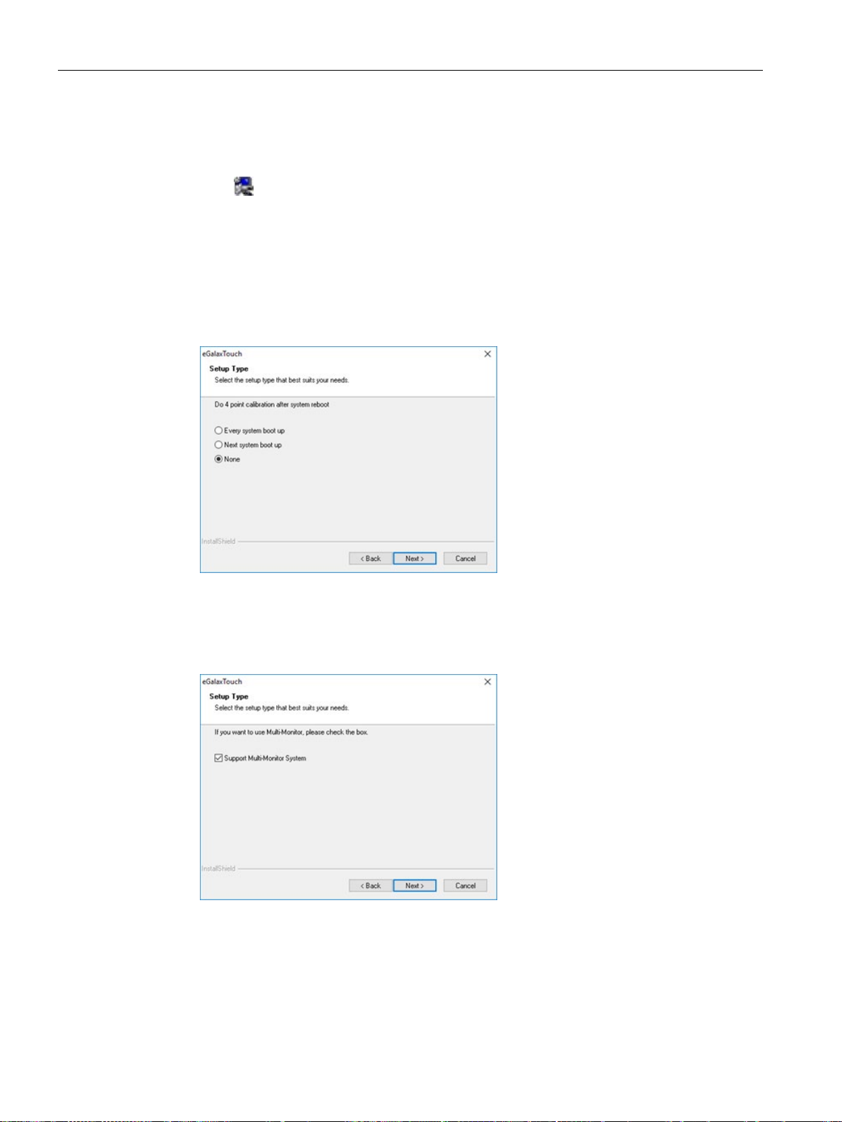
7. Select the setup type that suits you needs and click
to install the touch driver.
to confirm the user account control question.
to continue.
agreement" to accept license agreement and Click
to continue.
.
.
8. If you need to support Multi-monitor, select the radio button next to
System" and click
9. Select the folder where you want install the touch driver and click
10.Click
11.Click
to move on.
The installation starts.
.
.
"Support Multi-monitor
.
IFP Basic
38 Operating Instructions, 03/2019, A5E46178354 - AB
Page 39

4
Requirement
Note
The supplied connecting cables are only intended for commissioning and not for
continuous operation.
Procedure
If you operate the device exclusively as monitor and do not change the brightness, you do
not need to commission the device. To use advanced functions of the device, perform the
following commissioning.
● The Industrial Flat Panel is mounted according to the Quick Install Guide.
● The Industrial Flat Panel is connected according to the Quick Install Guide and connected
to a PC for commissioning.
● DVD "Documentation and Drivers"
1. Switch on the PC.
2. Switch on the power supply of the IFP Basic.
3. Insert the "Documentation and Drivers" DVD into the CD/DVD drive of the PC.
Alternative: Insert the USB stick with the copy of the DVD into a USB port on the PC.
4. Follow the instructions for installation.
IFP Basic
Operating Instructions, 03/2019, A5E46178354 - AB
39
Page 40
5
5.1
Operator input options
CAUTION
Unintentional actions with touch screen operation
NOTICE
Damage to the touch screen
Depending on your device and the connected I/O devices, the following operator input
options are available:
● Touch screen for touch device
If you touch the touch screen while system-internal processes are running, unintended
reactions of the device may be triggered.
Do not touch the screen in the following situations:
• During the boot process
• When plugging or unplugging USB components
• While Scandisk is running
• During a BIOS update
Hitting the touch screen with hard objects may damage it and can result in a total failure
of the touch screen.
Only touch the touch screen with your fingers or a suitable touch stylus.
● External keyboard, connected via USB
● External mouse, connected via USB
IFP Basic
40 Operating Instructions, 03/2019, A5E46178354 - AB
Page 41

Operating the device
5.2
Operating a device with resistive single touch screen
WARNING
Personal injury or property damage due to incorrect operation
NOTICE
Damage to the touch screen
Note
Appearance of blisters under extreme ambient conditions
Under extreme environmental conditions such as high atmospheric humidity and
temperature, bubbles can form on the touch surface in rare cases. This only affects the
appearance and does not represent any functional restriction.
5.2 Operating a device with resistive single touch screen
When you touch an object on the single touch screen, the corresponding function is
performed.
Incorrect operation of devices with a touch screen can occur. This can result in personal
injury or property damage.
Take the following precautions:
• Configure the plant so that safety-related functions are not operated with the touch
screen.
• Always touch only a single point on the touch screen.
• Calibrate the touch screen, at the latest when the touch screen becomes inaccurate or
does not respond despite repeated touches.
• Switch off the device for cleaning and maintenance.
• Make sure that the touch screen is kept free of dirt.
Touching the touch screen with pointed or sharp objects can damage it and lead to a
significant reduction in service life or even total failure of the touch screen.
Do not touch the touch screen with pointed or hard objects. Only touch the touch screen
with your fingers, a touch stylus or an approved touch glove.
IFP Basic
Operating Instructions, 03/2019, A5E46178354 - AB
41
Page 42
Operating the device
5.3
Using the Brightness Adjustment Tool
Adjust the brightness
Set the brightness at system startup to 100%
Adjust the VGA display
AUTO ADJUST
5.3 Using the Brightness Adjustment Tool
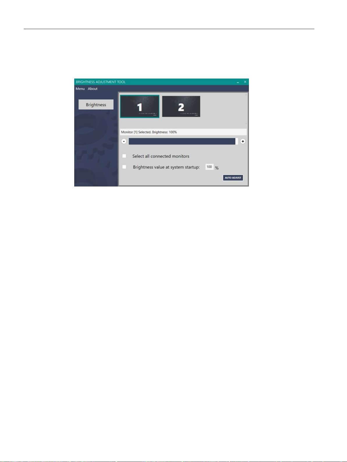
Ensure you have installed the Brightness Adjustment Tool.
1. Click the monitor to select the monitor you want to adjust the brightness.
– To select multiple monitors, click the connected monitors one by one. You can select
all connected monitors by ticking "Select all connected monitors".
– To unselect the monitor, click the selected monitor again.
2. Adjust the brightness in either of the following ways:
– click "+" or "-"
– Drag and drop the brightness slider.
Tick "set the brightness value at system start up".
When the VGA display is abnormal (for example, incomplete display), you can adjust the
display as the following steps:
1. Click the monitor to select the monitor you want to adjust the display.
2. Click "AUTO ADJUST".
For more information on the VGA display, refer to Troubleshooting (Page 69).
IFP Basic
42 Operating Instructions, 03/2019, A5E46178354 - AB
Page 43
Operating the device
AUTO Color
Note
The current color setting cannot be restored after you select "AUTO Color".
5.4
Using the touch driver
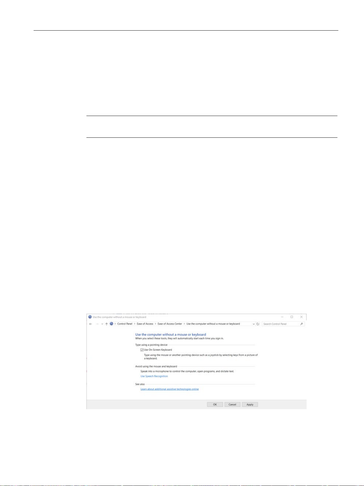
Open the On-Screen touch Keyboard
Start
Settings --> Ease of Access --> Keyboard
On-screen Keyboard
Enable start On-Screen Keyboard each time you sign in
Control Panel-->Ease of Access Center --> Use the computer without a mouse or
keyboard,
5.4 Using the touch driver
When the VGA color display is abnormal, you can adjust the color as the following steps:
1. Click the monitor to select the monitor you want to adjust the color.
2. Open a picture which only contains black and white color as the background.
3. Select "Menu" --> "AUTO Color".
This chapter provides some tips on using the touch driver. For more information on using the
touch driver, refer to the driver help in the "Documentation and Drivers" DVD.
Siemens recommends you to turn on the On-Screen Keyboard for entering characters.
Go to
, then select
under Use the
A keyboard that can be used to move around the screen and enter text will appear on the
screen. The keyboard will remain on the screen until you close it.
.
Go to
Select the radio button next to "Use On-Screen Keyboard".
, and turn on the toggle
IFP Basic
Operating Instructions, 03/2019, A5E46178354 - AB
43
Page 44
Operating the device
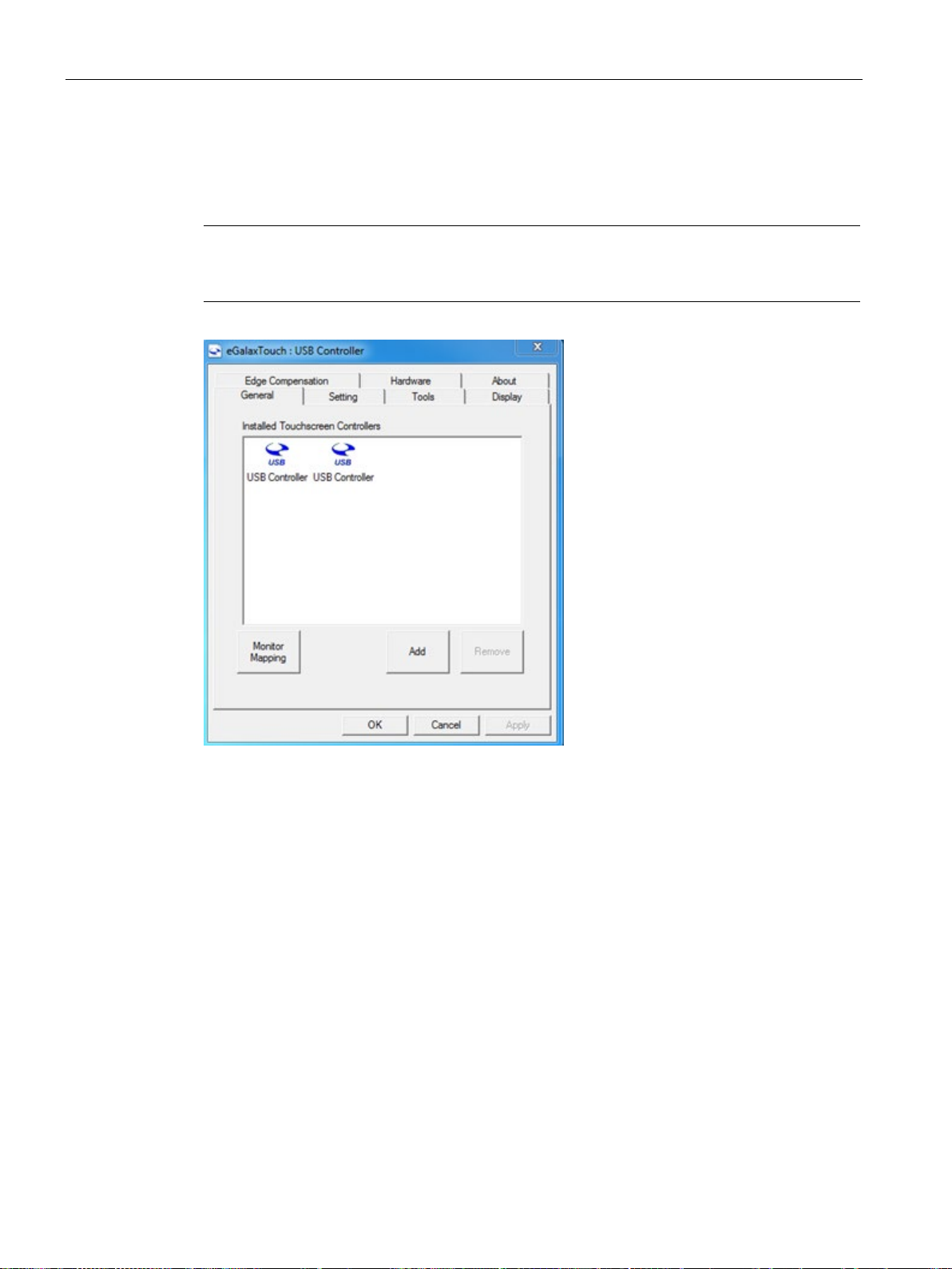
Assign name to the monitors
eGalaxTouch
Note
To distinguish the monitor, you can connect one monitor and change its name and then
connect the second monitor.
5.4 Using the touch driver
uses the same name for all the monitors it detects, Siemens recommend you
change the touch's name after you connect it.
IFP Basic
44 Operating Instructions, 03/2019, A5E46178354 - AB
Page 45
Operating the device
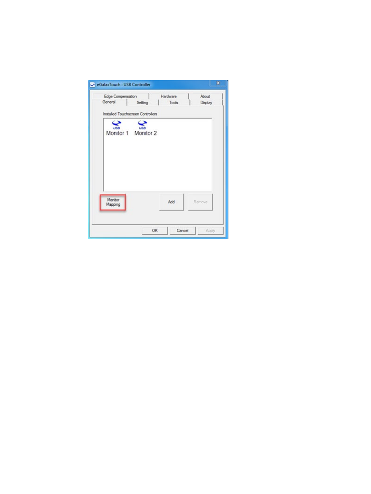
Map the monitor
5.4 Using the touch driver
If you use multiple monitors, do map the monitor after you connected them.
IFP Basic
Operating Instructions, 03/2019, A5E46178354 - AB
45
Page 46
Operating the device
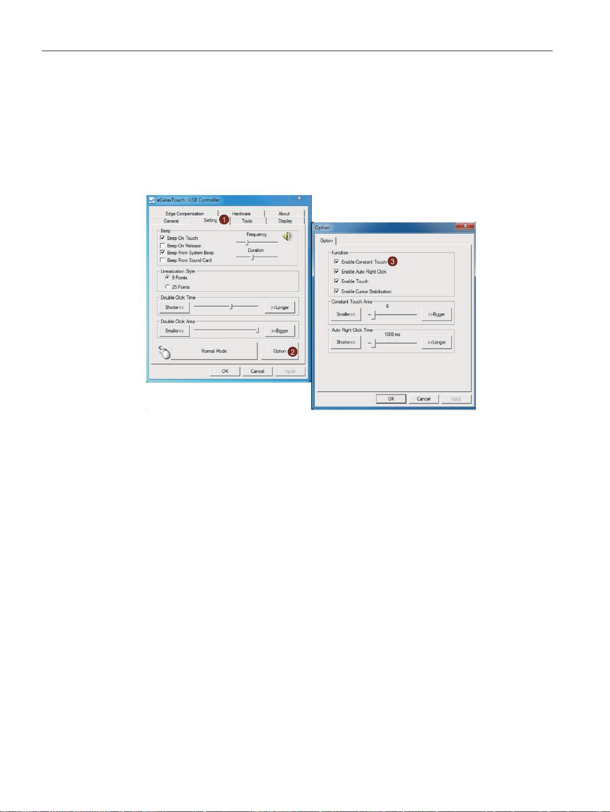
Adjust constant touch area
Setting-->option
Normal Mode
Enable constant touch
Normal mode
5.4 Using the touch driver
To adjust the constant touch area, follow the below steps:
1. Click
2. Select
3. Select the radio button next to "Enable constant touch", and adjust the constant touch
area by clicking "Bigger" and "Smaller" or slide the slider.
.
.
To enable constant touch, set the mode as
in the setting page.
IFP Basic
46 Operating Instructions, 03/2019, A5E46178354 - AB
Page 47

6
6.1
General information on maintenance and servicing
6.2
Cleaning the screen
Scope of maintenance
Note
When dust has collected on the device, the dust deposits must be removed at appropriate
time intervals.
Cleaning agents
NOTICE
Damage to the device caused by impermissible cleaning agents
Procedure
Observe the following when servicing and repairing protective features such as ground
circuits, overvoltage protection components or batteries:
● Observe the maintenance and replacement intervals specified by the respective
manufacturer for all system components.
● Replace system components, including cables, fuses and batteries only with equivalent
components approved by the respective manufacturer.
Use dish soap or foaming screen cleaner only as cleaning agents.
Impermissible and unsuitable cleaning agents may cause damage to the device.
Use dish soap or foaming screen cleaner only as cleaning agents. Do not use the following
cleaning agents:
• Aggressive solvents or scouring powder
• Steam jets
• Compressed air
1. Switch off the device. This prevents the accidental triggering of functions when the screen
is touched.
IFP Basic
Operating Instructions, 03/2019, A5E46178354 - AB
2. Dampen the cleaning cloth.
47
Page 48
Maintaining and servicing your device
6.3
Spare parts and repairs
WARNING
Risk of bodily injury or equipment damage due to unauthorized opening or repairing
6.4
Recycling and disposal
6.3 Spare parts and repairs
3. Spray the cleaning agent on the cloth and not directly on the device.
4. Clean the device with the cleaning cloth.
Bodily injury or considerable equipment damage may result from the unauthorized opening
or repairing of the device. Do not carry out any repairs on your own. Repairs may only be
carried out by authorized qualified personnel at the manufacturer's site.
In case of repair, the device must be shipped to the Return Center in Erlangen. Only repair
by the Return Center in Erlangen is permitted.
Depending on the work necessary to repair the device, the Center may decide to give you a
credit. In this case, it is your responsibility to order a new device.
The address is:
Siemens AG
Industry Sector
Postfach 48 48
900260 Nuremberg Germany
The devices described in these operating instructions can be recycled thanks to their low
level of pollutants. Contact a certified disposal service company for environmentally sound
recycling and disposal of your old devices.
IFP Basic
48 Operating Instructions, 03/2019, A5E46178354 - AB
Page 49

7
7.1
Certificates and approvals
Note
Approvals on the rating plate
The following overview provides information on possible approvals.
Only the approvals on the rati
CE marking
EU Declarations of Conformity
Software license agreements
ng plate of the specific device apply.
The devices meet the general and safety-related requirements of the following EU directives
and conform to the harmonized European standards (EN) for these devices published in the
official gazettes of the European Community and in the EU Declarations of Conformity:
● 2014/35/EU "Electrical equipment for use within certain voltage limits" (Low-Voltage
Directive)
● 2014/30/EU "Electromagnetic Compatibility Directive" (EMC Directive)
● 2011/65/EU "Directive of the European Parliament and of the Council of 8 June 2011 on
the restriction of the use of certain hazardous substances in electrical and electronic
equipment" (RoHS Directive)
When the device has Ex approval (see nameplate below), the following also applies:
● 2014/34/EU "Equipment and protective systems intended for use in potentially
explosive atmospheres" (Directive for Explosion Protection)
The EU Declarations of Conformity are available to the relevant authorities at the following
address:IFP Basic certifications
(https://support.industry.siemens.com/cs/ww/en/ps/16788/cert)
Siemens AG
Digital Factory
Factory Automation
DF FA AS SYS
P.O. Box 1963
D-92209 Amberg, Germany
If the device is supplied with preinstalled software, you must observe the corresponding
license agreements.
IFP Basic
Operating Instructions, 03/2019, A5E46178354 - AB
49
Page 50
Technical information
UL approval
FCC and Canada
USA
ference at his own expense.
FCC regulations.
void the user's authority to operate the equipment.
may cause undesired operation.
CANADA
Canadian Notice
This Class A digital apparatus complies with Canadian ICES-003 (A).
003 (A) du Canada.
Responsible party for Supplier's Declaration of Conformity
7.1 Certificates and approvals
See the following notes:
● The device shall be supplied from an isolating source, rated 24 VDC.
The following approvals are available for the device:
● Underwriters Laboratories (UL) in accordance with Standard UL61010-1 and UL61010-2-
201 (IND.CONT.EQ), File E472609
● Canadian National Standard CAN/CSA No.61010-1-12 and CAN/CSA C22.2 No.61010-2-
201
Federal Communications Commission
Radio Frequency
Interference
Statement
Shielded Cables Shielded cables must be used with this equipment to maintain compliance with
Modifications Changes or modifications not expressly approved by the manufacturer could
Conditions of
Operations
Avis Canadien Cet appareil numérique de la classe A est conforme à la norme NMB-
This equipment has been tested and found to comply with the limits for a Class
A digital device, pursuant to Part 15 of the FCC Rules. These limits are designed
to provide reasonable protection against harmful interference when the equipment is operated in a commercial environment. This equipment generates, uses,
and can radiate radio frequency energy and, if not installed and used in accordance with the instruction manual, may cause harmful interference to radio communications. Operation of this equipment in a residential area is likely to cause
harmful interference in which case the user will be required to correct the inter-
This device complies with Part 15 of the FCC Rules. Operation is subject to the
following two conditions: (1) this device may not cause harmful interference, and
(2) this device must accept any interference received, including interference that
Siemens Industry, Inc.
Digital Factory - Factory Automation
5300 Triangle Parkway, Suite 100
Norcross, GA 30092
USA
Mail to: ([email protected])
IFP Basic
50 Operating Instructions, 03/2019, A5E46178354 - AB
Page 51

Technical information
KOREA
Identification for Eurasion Customs Union
WEEE label (European Union)
7.2
Directives and declarations
7.2.1
ESD guideline
What does ESD mean?
7.2 Directives and declarations
This product meets the requirements of Korean certification.
This product satisfies the requirement of the Korean Certification (KC Mark).
이 기기는 업무용(A 급) 전자파 적합기기로서 판매자 또는 사용자는 이 점을 주의하시기
바라며 가정 외의 지역에서 사용하는 것을 목적으로 합니다.
Note that this device conforms to Limit Class A for emission of radio interference. This
device can be used in all areas except the residential area.
● EAC (Eurasian Conformity)
● Customs union of Russia, Belarus and Kazakhstan
● Declaration of conformity according to Technical Regulations of the Customs Union (TR
CU)
Disposal instructions, observe the local regulations and the section "Recycling and disposal
(Page 48)".
An electronic module is equipped with highly integrated components. Due to their design,
electronic components are highly sensitive to overvoltage and thus to the discharge of static
electricity. Such electronic components or modules are labeled as electrostatic sensitive
devices.
The following abbreviations are commonly used for electrostatic sensitive devices:
● ESD – Electrostatic sensitive device
● ESD – Electrostatic Sensitive Device as a common international designation
Electrostatic sensitive devices can be labeled with an appropriate symbol.
IFP Basic
Operating Instructions, 03/2019, A5E46178354 - AB
51
Page 52
Technical information
NOTICE
Damage to ESD from touch
mage to a module by an overvoltage can often not be immediately detected and only
Charge
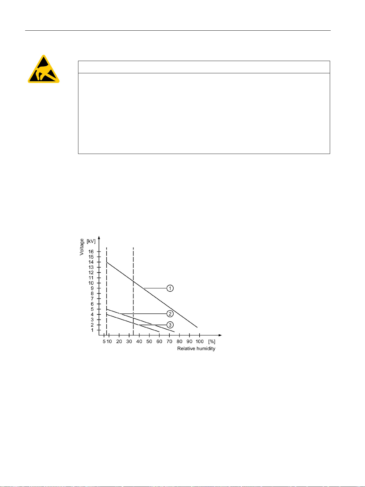
①
Synthetic materials
②
Wool
③
Antistatic materials such as wood or concrete
7.2 Directives and declarations
Electrostatic sensitive devices, ESD, can be destroyed by voltages which are far below the
human perception limit. If you touch a component or electrical connections of a module
without discharging any electrostatic energy, these voltages may arise.
The da
becomes evident after an extended period of operation. The consequences are incalculable
and range from unforeseeable malfunctions to a total failure of the machine or system.
Avoid touching components directly. Make sure that persons, the workstation and the
packaging are properly grounded.
Every person without a conductive connection to the electrical potential of his/her
surroundings can be electrostatically charged.
The material with which this person comes into contact is of particular significance. The
figure shows the maximum electrostatic voltages with which a person is charged, depending
on humidity and material. These values conform to the specifications of IEC 61000-4-2.
IFP Basic
52 Operating Instructions, 03/2019, A5E46178354 - AB
Page 53

Technical information
NOTICE
Grounding measures
Protective measures against discharge of static electricity
7.2 Directives and declarations
There is no equipotential bonding without grounding. An electrostatic charge is not
discharged and may damage the ESD.
Protect yourself against discharge of static electricity. When working with electrostatic
sensitive devices, make sure that the person and the workplace are properly grounded.
● Disconnect the power supply before you install or remove modules which are sensitive to
ESD.
● Pay attention to good grounding:
– When handling electrostatical sensitive devices, make sure that persons, the
workstation and devices, tools and packaging used are properly grounded. This way
you avoid static discharge.
● Avoid direct contact:
– As a general rule, do not touch electrostatic sensitive devices, except in the case of
unavoidable maintenance work.
– Hold the modules at their edge so that you do not touch the connector pins or
conductor paths. This way, the discharge energy does not reach and damage the
sensitive components.
– Discharge your body electrostatically before you take a measurement at a module. Do
so by touching grounded metallic parts. Always use grounded measuring instruments.
IFP Basic
Operating Instructions, 03/2019, A5E46178354 - AB
53
Page 54
Technical information
7.3
Dimension drawings
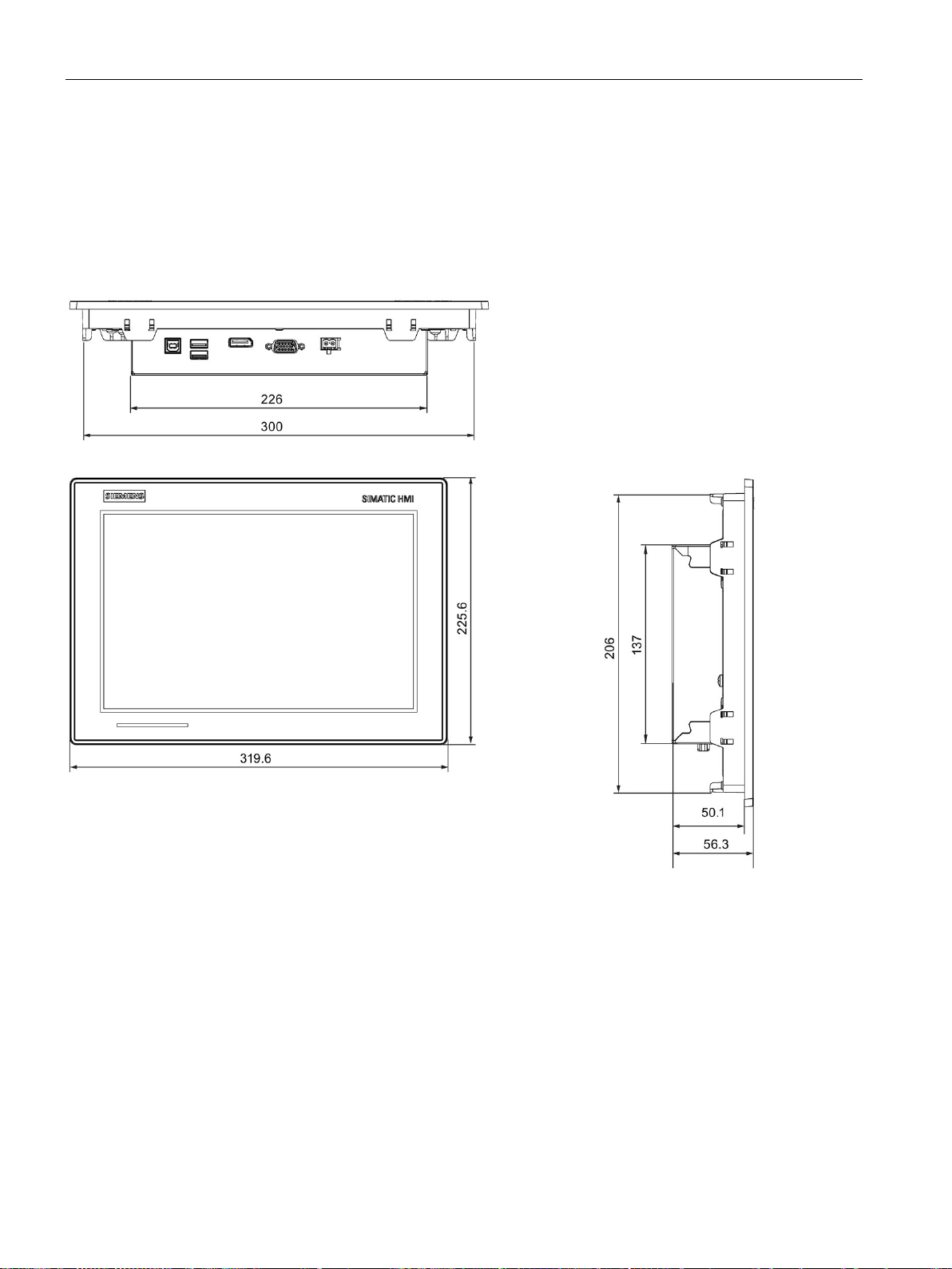
7.3.1
Dimension drawing of the IFP1200 Basic
7.3 Dimension drawings
All dimensions in mm
IFP Basic
54 Operating Instructions, 03/2019, A5E46178354 - AB
Page 55
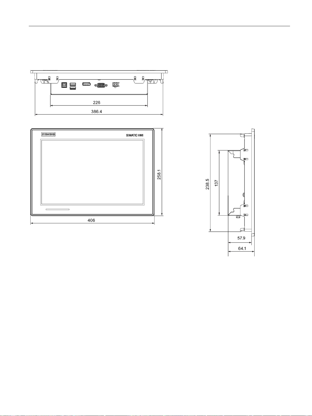
Technical information
7.3.2
Dimension drawing of the IFP1500 Basic
7.3 Dimension drawings
All dimensions in mm
IFP Basic
Operating Instructions, 03/2019, A5E46178354 - AB
55
Page 56
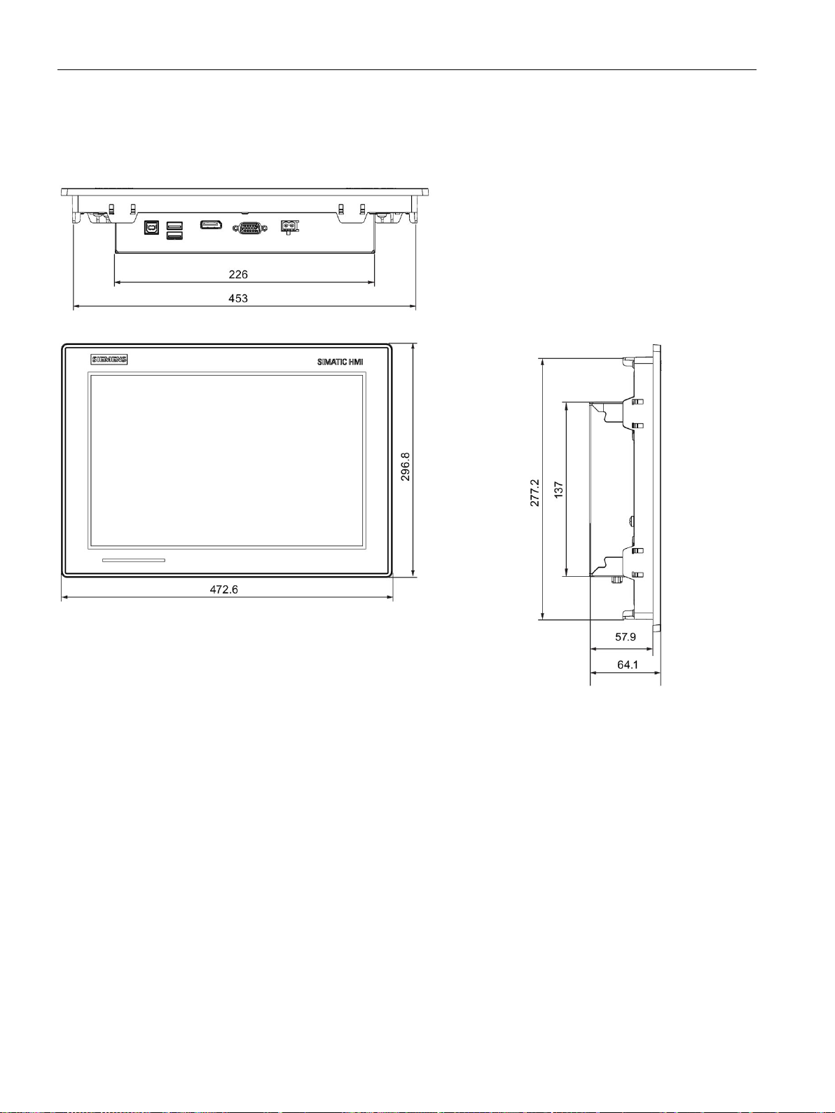
Technical information
7.3.3
Dimension drawing of the IFP1900 Basic
7.3 Dimension drawings
All dimensions in mm
IFP Basic
56 Operating Instructions, 03/2019, A5E46178354 - AB
Page 57
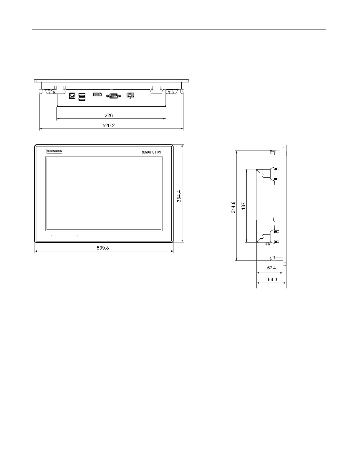
Technical information
7.3.4
Dimension drawing of the IFP2200 Basic
7.3 Dimension drawings
All dimensions in mm
IFP Basic
Operating Instructions, 03/2019, A5E46178354 - AB
57
Page 58
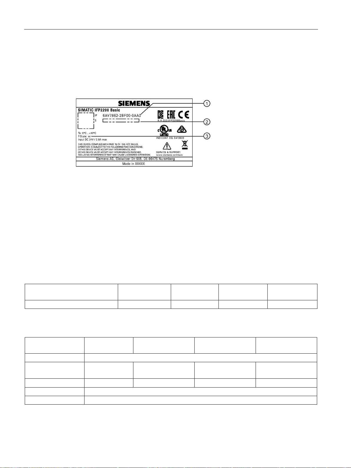
Technical information
7.4
Rating plate
①
Order number
②
Serial number
③
Production version
7.5
Technical specifications
7.5.1
General technical specifications
Weight of IFP Basic
SIMATIC IFP1200
Basic
SIMATIC IFP1500
Basic
SIMATIC IFP1900
Basic
SIMATIC IFP2200
Basic
Weight without packaging, approx.
2.7 kg
4.1 kg
5.1 kg
6.5 kg
Display
SIMATIC IFP1200
Basic
SIMATIC IFP1500
Basic
SIMATIC IFP1900
Basic
SIMATIC IFP2200
Basic
Type
LCD widescreen TFT
307 × 191 mm
331.2 × 207 mm
409.8 × 230.4 mm
475.2 × 267.3 mm
Resolution
1280 x 800 pixels
1366 x 768 pixels
1366 x 768 pixels
1920 x 1080 pixels
Possible colors
Up to 16 million
Brightness control
By means of Brightness Adjustment Tool, value range 0 to 100%
7.4 Rating plate
The rating plate includes information that clearly identifies your device. You need this
information when you contact Customer Support.
The figure below shows an example of a rating plate.
Active display area 12.1''
15.6''
18.5''
21.5''
IFP Basic
58 Operating Instructions, 03/2019, A5E46178354 - AB
Page 59

Technical information
SIMATIC IFP1200
Basic
SIMATIC IFP1500
Basic
SIMATIC IFP1900
Basic
SIMATIC IFP2200
Basic
Time (MTBF 1)
ISO 9241-307
1
via PROFIenergy.
Input device
SIMATIC IFP1200 / IFP1500 / IFP1900 / IFP2200 Basic
Keyboard
Externally via USB
Touch screen
Analog resistive single touch screen
Interfaces
USB Type A, rear
USB Type B, rear
DisplayPort
VGA
IPF2200 Basic
1
USB type A, maximum load 500 mA, equivalent to USB standard 2.0
DC power supply
SIMATIC IFP1200 Basic
SIMATIC IFP1500 Basic
SIMATIC
IFP1900
Basic
SIMATIC IFP2200
Basic
Permitted voltage range
+20.4 V to + 28.8 V
Inrush current I2t
Maximum 2.5 A, 15 ms
Power consumption 1
13 W
17 W
19 W
24 W
Maximum permitted transients
35 V (500 ms)
sients
1
The power loss generally corresponds to the specified value for power consumption.
7.5 Technical specifications
Backlighting
Half Brightness Life
Pixel error class in
LED
50000 h
LED
30000 h
II
accordance with
MTBF: Operating hours after which the maximum screen brightness is reduced by half compared to the original value.
MTBF is increased by using the integrated dimming function, for example time-controlled via screen saver or centrally
IFP1200 / IFP1500 / IFP1900 /
2 1 1 1
Rated voltage
Minimum time between two tran-
Internal protection Electronic
IFP Basic
Operating Instructions, 03/2019, A5E46178354 - AB
24 V DC
50 s
59
Page 60

Technical information
7.5.2
Ambient conditions
7.5.2.1
Transport and storage conditions
Mechanical transport and storage conditions
Type of condition
Permitted range
Free fall
≤ 1 m
Shock according to IEC 60068-2-27
250 m/s2, 6 ms, 1000 shocks
Climatic transport and storage conditions
Type of condition
Permitted range
Temperature
–20 to 60 °C
altitude
Relative humidity
5% to 95% at 25/55 °C, no condensation
Note
If dewing has developed, wait until the HMI device has dried completely before switching it
on.
Do not expose the HMI device to direct radiation from a heater.
7.5 Technical specifications
Proper transport and storage, installation and assembly as well as careful operation and
maintenance are prerequisites for trouble-free and safe operation of the device.
Non-compliance with these regulations shall render the device warranty void.
The following information is for a device that is transported and stored in its original
packaging.
The device meets the requirements according to IEC 60721-3-2 Class 2M2 with the following
amendments and limitations:
Vibration according to IEC 60068-2-6 5 to 8.4 Hz, deflection 3.5 mm
The following information applies to a device that is transported in the original packaging and
weather-proof packaging, and stored from some time.
8.4 to 500 Hz, acceleration 1 g
The device meets the requirements according to IEC 60721-3-2 Class 2K4 with the following
amendments and limitations:
Atmospheric pressure,
1080 to 660 hPa, corresponds to an elevation of -1000 to 3500 m
IFP Basic
60 Operating Instructions, 03/2019, A5E46178354 - AB
Page 61

Technical information
7.5.2.2
Operating conditions
Mechanical and climatic conditions of use
Mechanical ambient conditions
Frequency range f in Hz
Constant
Occasional
5 to 8.4 Hz
Amplitude 0.0375 mm
Amplitude 3.5 mm
8.4 to 200 Hz
Constant acceleration 0.5 g
Constant acceleration 1 g
Testing mechanical ambient conditions
Tested for
Test standard
Comments
8.4 to 200 Hz, constant acceleration 0.5 g
tually vertical axes
Type of shock: Half-sine
Peak value 15 g, duration 11 ms
axes vertical to each other
7.5 Technical specifications
The device is designed for use in locations protected from the effects of the weather. The
conditions of use meet the requirements for DIN IEC 60721-3-3:
● Class 3M3 (mechanical requirements)
● Class 3K3 (climatic requirements)
The mechanical ambient conditions for the device are specified in the table below in terms of
sinusoidal vibration.
The table below provides information on the type and scope of tests for mechanical ambient
conditions.
Vibrations Vibration test in accordance
with IEC 60068, part 2-6
(sinusoidal)
Shock Shock test in accordance
with IEC 60068, Part 2-27
Type of vibration:
Frequency cycles at a rate of change of 1 oc-
tave/minute.
5 to 8.4 Hz, constant amplitude 0.0375 mm
Vibration duration:
10 frequency cycles per axis in each of the three mu-
Severity of shock:
Direction of shock:
3 shocks in ± direction of axis in each of the three
Shock pulses within the specified range can be transferred to the display but do not impact
the functionality of the device.
IFP Basic
Operating Instructions, 03/2019, A5E46178354 - AB
61
Page 62

Technical information
Climatic ambient conditions
Ambient conditions
Permitted range
Comments
0 to 45 °C
0 to 40 °C
tion
operation elevation
of -1000 to 3000 m
7.5.2.3
Electromagnetic compatibility
Pulse-shaped interference
Pulse-shaped interference
Test voltage
Degree of
severity
61000-4-2
Air discharge: ± 8 kV
3
IEC 61000-4-4
2 kV line-to-earth of DC port
DC voltage with protective elements
7.5 Technical specifications
The following table shows the climatic ambient conditions for operation of the device.
Temperature for IFP1200 /
IFP1500 / IFP 1900 Basic:
Temperature for IFP2200
Basic:
Relative humidity 10 to 85% at 30 °C, no condensa-
Atmospheric pressure,
Note the information in section "Notes about usage (Page 14)" .
The following table shows the electromagnetic compatibility of modules with regard to pulseshaped interference. This requires the device to meet the specifications and directives for
electrical installation.
• horizontal mounting
0 to 45 °C
• Vertical mounting
• horizontal mounting
0 to 40 °C
• Vertical mounting
1080 to 689 hPa Corresponds to an elevation
Tilt angle max. 45°
Tilt angle max. 45°
Electrostatic discharge
in accordance with IEC
Bursts
(high-speed transient
interference)
in accordance with
Surge in accordance with
IEC 61000-4-5
Asymmetrical coupling ± 2 kV power supply cable
Symmetrical coupling 1 kV power supply cable
IFP Basic
62 Operating Instructions, 03/2019, A5E46178354 - AB
Contact discharge: ± 4 kV 2
± 2 kV power supply cable
± 1 kV signal cable, < 30 m
1 kV line-to-line of DC port
DC voltage with protective elements
3
3
3
Page 63

Technical information
Sinusoidal interference
Sinusoidal interference
Test values
Degree of
severity
IEC 61000-4-3
with 3 V/m in the range 2 GHz to 6 GHz
IEC 61000-4-6
Emission of radio interference
Radiated emission (emitted interference)
1 GHz to 3 GHz
< 76 dB peak and < 56 dB average
3 GHz to 6 GHz
< 80 dB peak and < 60 dB average
30 MHz to 230 MHz
< 40 dB (μV/m) quasi-peak
230 MHz to 1000 MHz
< 47 dB (μV/m) quasi-peak
Emission of radio interference voltages
0.150 MHz to 0.5 MHz
< 79 dB quasi-peak and < 66 dB average
0.5 MHz to 30 MHz
< 73 dB quasi-peak and < 60 dB average
See also
7.5 Technical specifications
The following table shows the EMC behavior of the modules with respect to sinusoidal
interference. This requires the HMI device to meet the specifications and directives for
electrical installation.
HF radiation (electromagnetic fields)
according to
HF power applied to
lines and line shields
according
The following table shows the emitted interference from electromagnetic fields according to
EN 61000-6-4, measured at a distance of 10 m.
80% amplitude modulation at 1 kHz
with 10 V/m in the range of 80 MHz to 1 GHz
with 3 V/m in the range 1.4 GHz to 2 GHz
Test voltage 10 V, with 80% amplitude modulation of 1 kHz
in the 150 kHz to 80 MHz range
3
3
Notes about usage (Page 14)
Industrial support (https://support.industry.siemens.com)
IFP Basic
Operating Instructions, 03/2019, A5E46178354 - AB
63
Page 64

Technical information
7.5.2.4
Information on protection class and degree of protection
Protection class
Protection against foreign objects and water
Degree of protection
Explanation
1
The degree of protection of the front panel can only be guaranteed if the mounting seal
is properly installed at the cabinet.
2
The degree of protection of the rear panel can only be guaranteed when all the interface
are plugged in.
Degree of pollution / overvoltage category according to IEC 61010
7.5 Technical specifications
Protection Class III in accordance with IEC 61010-1, for example. with protective conductor.
Front When mounted:
• IP65 according to IEC 60529
Rear panel
• IP40 for IFP1200 Basic, IFP1500 Basic, IFP1900 Basic
• IP20 for IFP2200 Basic
1
2
2
Degree of pollution 2
IFP Basic
64 Operating Instructions, 03/2019, A5E46178354 - AB
Page 65
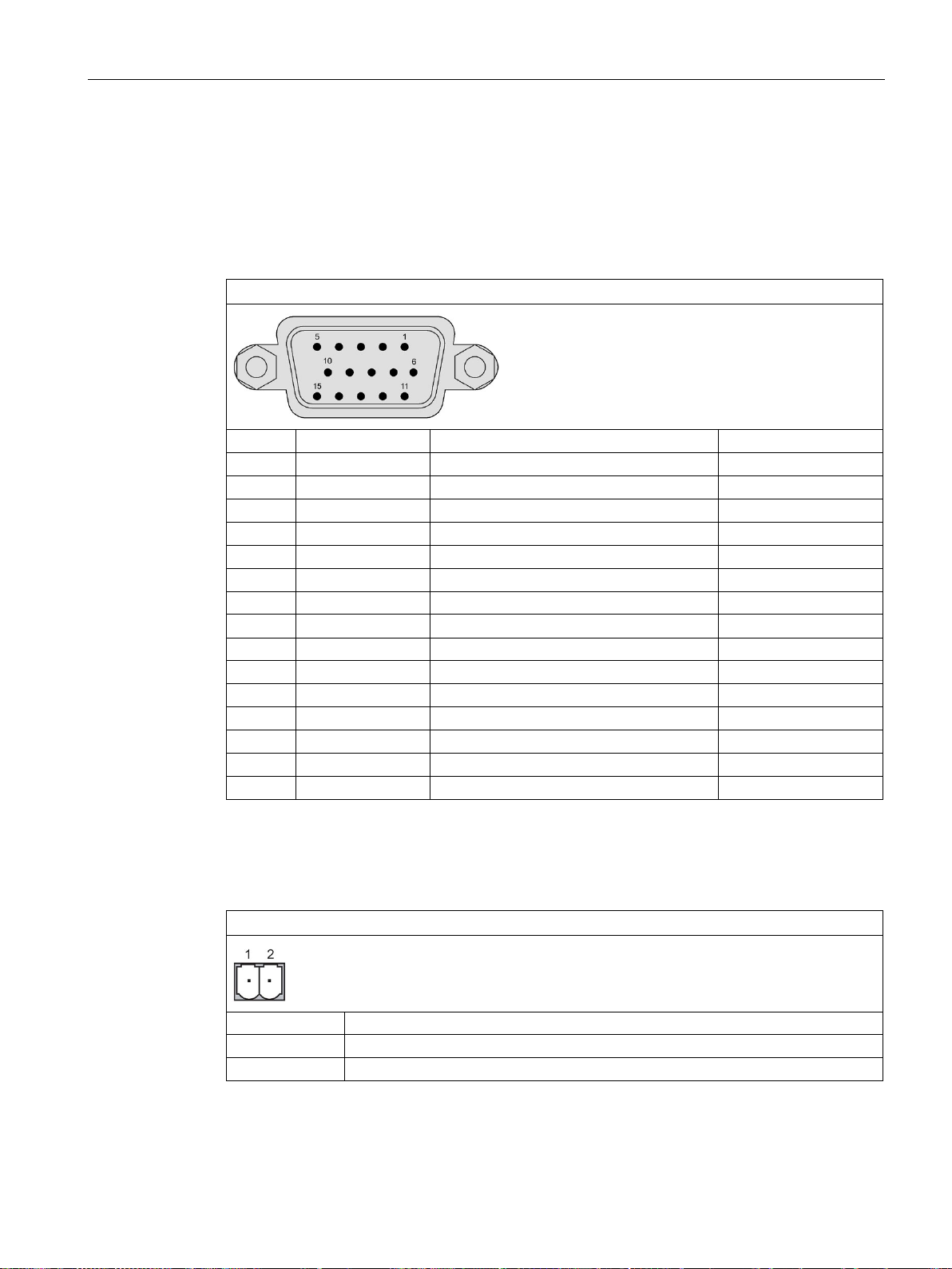
Technical information
7.6
Interface description
7.6.1
VGA interface
VGA interface
Pin no.
Abbreviation
Meaning
Input/output
1
R+
Red+
Input
2
G+
Green+
Input
3
B+
Blue+
Input
4
NC
No connection
-
5
Cable_DET
VGA cable detection
Input
6
R-
Red-
Input
7
G-
Green-
Input
9
VCC
VGA cable power
power
10
Ground
Ground
Ground
11
NC
No Connection
-
12
SDA
DDC data
Bidirectional
13
HSYNC
Horizontal Synchronization
Input
14
VSYNC
Vertical Synchronization
Input
15
SCL
DDC clock
Bidirectional
7.6.2
24 VDC Power Supply
Power supply 24 VDC 2-pin
Pin no.
Meaning
1
+24 VDC
2
GND
7.6 Interface description
8 B- Blue- Input
IFP Basic
Operating Instructions, 03/2019, A5E46178354 - AB
65
Page 66
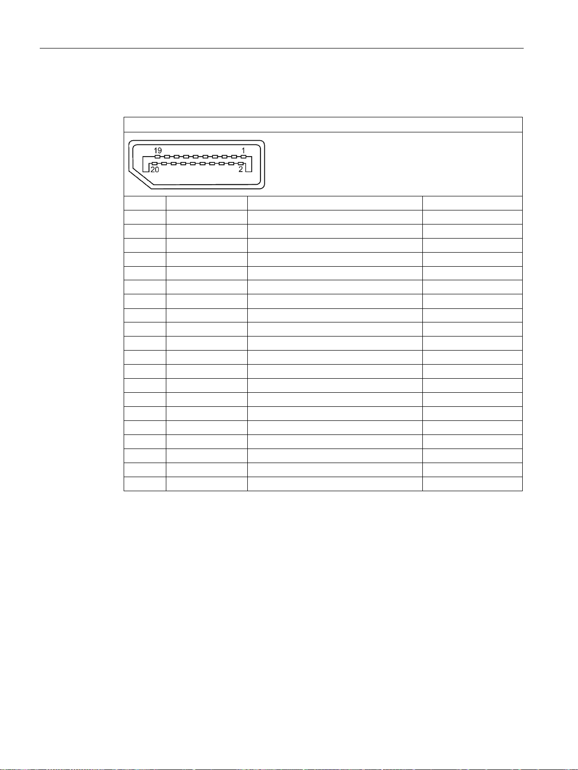
Technical information
7.6.3
DisplayPort
DisplayPort interface
Pin no.
Abbreviation
Meaning
Input/output
1
ML_Lane3-
DP data 3-
Input
2
GND
Ground
-
3
ML_Lane3+
DP data 3+
Input
4
ML_Lane2-
DP data 2-
Input
5
GND
Ground
- 6 ML_Lane2+
DP data 2+
Input
8
GND
Ground
-
9
ML_Lane1+
DP data 1+
Input
10
ML_Lane0-
DP data 0-
Input
11
GND
Ground
-
12
ML_Lane0+
DP data 0+
Input
13
CONFIG1
CONFIG1
-
14
CONFIG2
CONFIG2
-
15
AUX_CH+
Auxiliary channel+
Bidirectional
16
GND
Ground
-
17
AUX_CH-
Auxiliary channel-
Bidirectional
18
HPD
Hot Plug Detect
output
19
GND
Ground
-
20
DP_PWR
+3.3 V (fused)
power out
7.6 Interface description
7 ML_Lane1- DP data 1- Input
IFP Basic
66 Operating Instructions, 03/2019, A5E46178354 - AB
Page 67
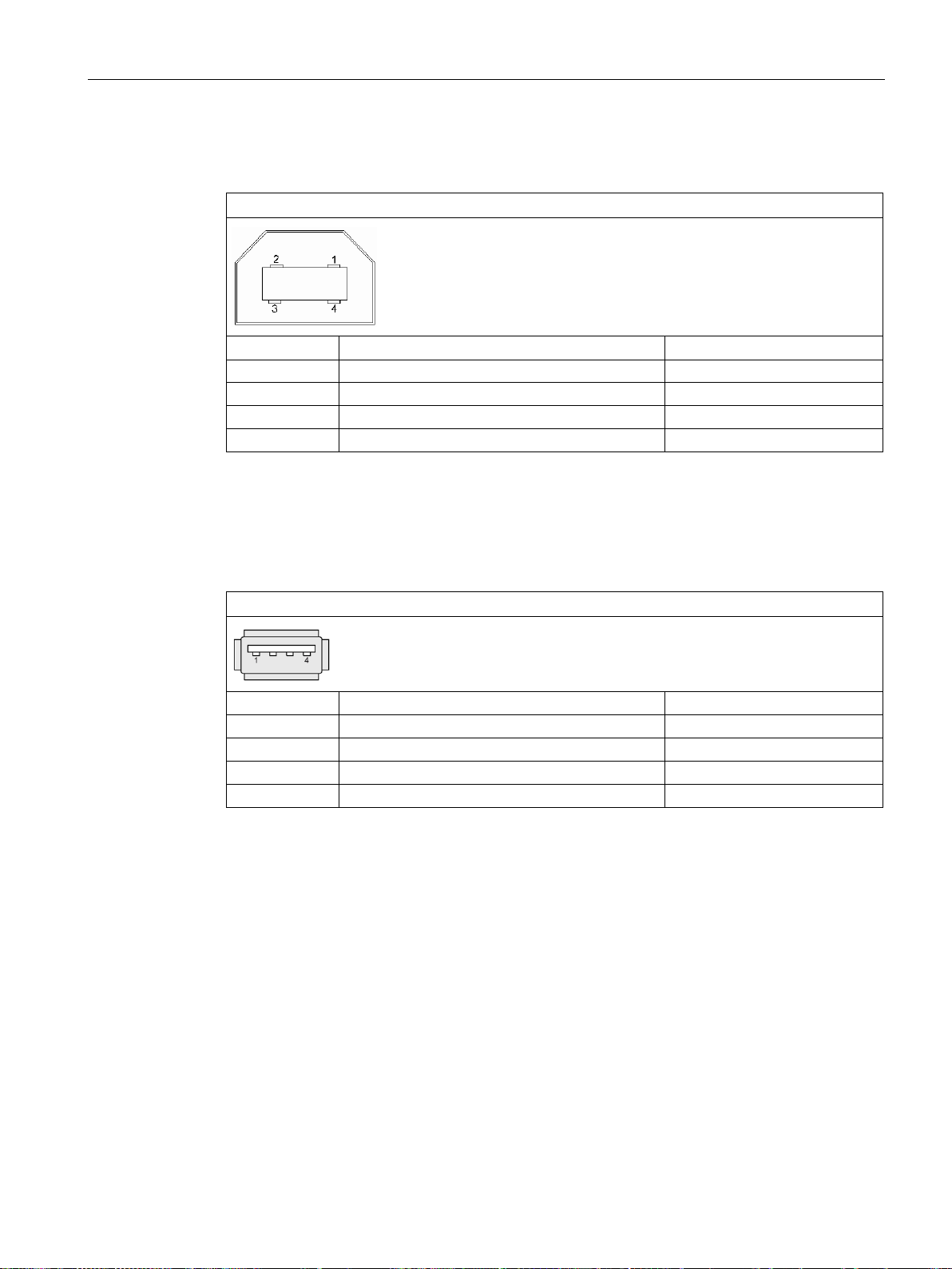
Technical information
7.6.4
USB interface, Type B
USB port, Type B
Pin no.
Abbreviation
Signal
1
VCC
+ 5 V (fused)
2
- Data
Data channel
3
+ Data
Data channel
4
GND
Ground
7.6.5
USB interface, Type A
USB port
Pin No.
Abbreviation
Signal
1
VCC
+ 5 V (fused)
2
- Data
Data channel
3
+ Data
Data channel
4
GND
Ground
7.6 Interface description
IFP Basic
Operating Instructions, 03/2019, A5E46178354 - AB
67
Page 68

A
A.1
Service and support
Current documentation
Tools & downloads
You can find additional information and support for the products described on the Internet at
the following addresses:
● Technical support
(https://support.industry.siemens.com/cs/start?lc=en-WW)
● Support request form
(https://support.industry.siemens.com/My/ww/en/requests#createRequest)
● After Sales Information System SIMATIC IPC/PG
(http://www.siemens.com/asis)
● SIMATIC Documentation Collection
(http://www.siemens.com/simatic-tech-doku-portal)
● Your local representative
(http://w3.siemens.com/aspa_app/)
● Training center
(http://sitrain.automation.siemens.com/sitrainworld/?AppLang=en)
● Industry Mall
(https://mall.industry.siemens.com/)
When contacting your local representative or Technical Support, please have the following
information at hand:
● MLFB of the device
● BIOS version for industrial PC or image version of the device
● Other installed hardware
● Other installed software
Always use the current documentation available for your product. You can find the latest
edition of this manual and other important documents by entering the article number of your
device on the Internet (http://www.siemens.com/simatic-tech-doku-portal). If necessary, filter
the comments for the entry type "Manual".
Please check regularly if updates and hotfixes are available for download to your device. The
download area is available on the Internet at the following link:
After Sales Information System SIMATIC IPC/PG (http://www.siemens.com/asis)
IFP Basic
68 Operating Instructions, 03/2019, A5E46178354 - AB
Page 69

Technical Support
A.2
Troubleshooting
Ethernet Monitors
Error pattern
Possible cause
Possible remedy
A.2 Troubleshooting
The host cannot provide the
correct name and resolution
list of IFP Basic when you only
use VGA port.
The host cannot display correctly.
Make sure that you
insert the VGA port
correctly.
Make sure that you
select IFP Basic supported resolution.
Unplug the VGA port and wait until "Power saving" is displayed on the monitor.
Then plug the VGA port again.
When you plug the VGA port, pay attention to the following tips.
1. Insert the VGA port to the end.
2. Make sure you insert the VGA port
vertically.
3. Tighten the screw to lock the VGA
port into place.
Select the IFP Basic supported resolution:
12.1''
• 1280 x 800, @60Hz
• 1280 x 720, @60Hz
• 1024 x 768, @60Hz
• 800 x 600, @60Hz
15.6'' and 18.5"
• 1366 x 768, @60Hz
• 1280 x 720, @60Hz
• 1024 x 768, @60Hz
• 800 x 600, @60Hz
21.5"
• 1920 x 1080, @60Hz
• 1600 x 900, @60Hz
• 1400 x 1050, @60Hz
• 1280 x 1024, @75Hz
• 1280 x 960, @75Hz
• 1280 x 800, @60Hz
• 1280 x 720, @60Hz
• 1152 x 864, @75Hz
• 1024 x 768, @60Hz
• 800 x 600, @60Hz
IFP Basic
Operating Instructions, 03/2019, A5E46178354 - AB
69
Page 70
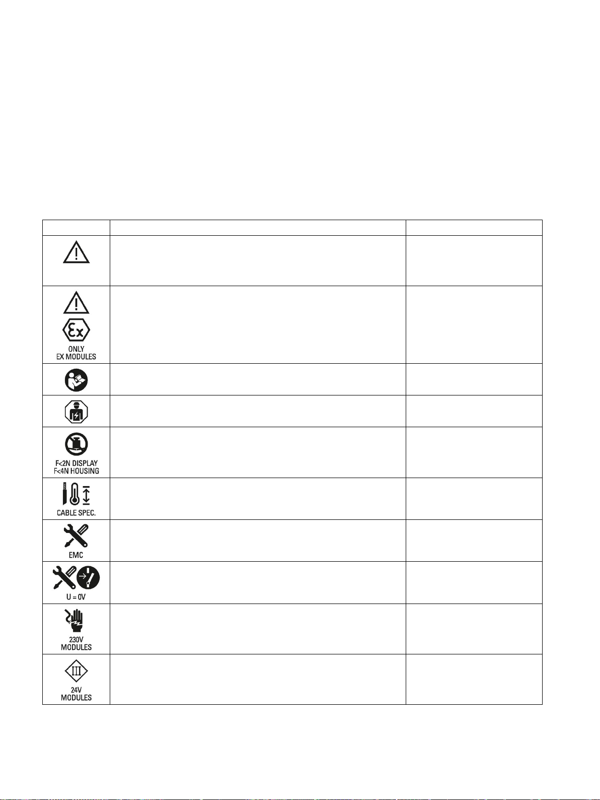
B
B.1
Safety-relevant symbols
Symbol
Meaning
Reference
you to identify risks and implement countermeasures.
The following table describes symbols that can be added to your SIMATIC device, to its
packaging or to an enclosed document in addition to the symbols described in the manuals.
General danger sign Caution / Attention
You must following the operating instructions. The operating instruc-
tions contain information on the type of the potential hazard and enable
Attention, only relevant for modules with Ex approval
Follow the instructions ISO 7010 M002
May be installed by qualified electricians only IEC 60417 No. 6182
Mechanical load for HMI devices
Connection cables must be designed for the ambient temperature
EMC-compliant installation
ISO 7000 No. 0434B,
DIN ISO 7000 No. 0434B
No mounting or pulling & plugging under voltage
Dangerous electrical voltage for 230V modules ANSI Z535.2
Protection class III, supply only with protective low voltage
(SELV/PELV)
IFP Basic
70 Operating Instructions, 03/2019, A5E46178354 - AB
IEC 60417-1-5180 "Class III
equipment"
Page 71
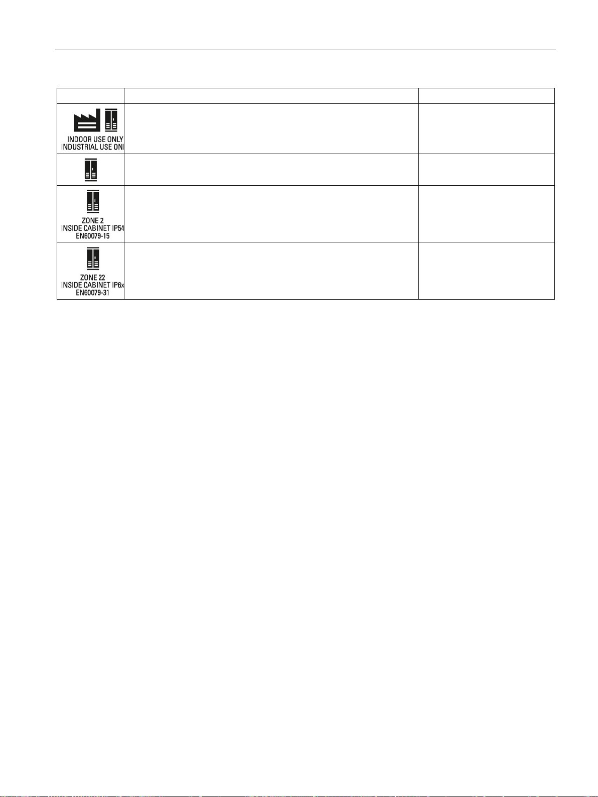
Markings and symbols
Symbol
Meaning
Reference
B.1 Safety-relevant symbols
Only for industrial applications and indoor areas (control cabinet)
Install in control cabinet only
Devices approved for Ex Zone 2 in a control cabinet with min. IP54
Devices approved for Ex Zone 22 in a control cabinet with min. IP6x
IFP Basic
Operating Instructions, 03/2019, A5E46178354 - AB
71
Page 72

C
ANSI
American National Standards Institute
ASCII
American Standard Code for Information Interchange
B
Width
BLI
Backlight Inverter
BIOS
Basic Input Output System
CD-ROM
Compact Disc – Read Only Memory
CPU
Central Processing Unit
DC
Direct Current
DNS
Domain Name Service
DP
Distributed I/O
DSN
Data Source Name
DVD-ROM
Digital Versatile Disc – Read Only Memory
ESD
Electrostatic Sensitive Devices
EMC
ElectroMagnetic Compatibility
H
Height
HF
High Frequency
HMI
Human Machine Interface
IF
Interface: Interface
LCD
Liquid Crystal Display: Liquid crystal display
LED
Light Emitting Diode: Light emitting diode
LPS
Limited Power Source
Mbps
Megabits per second
NBR
Nitrile butadiene rubber
OSD
OnScreenDisplay
OSK
OnScreenKeyboard
PC
Personal Computer
PG
Programming device
PPI
Point to Point Interface SIMATIC S7
PS/2
Personal System 2
ic equipment
T
Device depth
TCP/IP
Transmission Control Protocol/Internet Protocol
USB
Universal Serial Bus
VGA
Video Graphics Array
DHCP Dynamic Host Configuration Protocol
RoHS Restriction of the use of certain hazardous substances in electrical and electron-
PLC Programmable logic controller
IFP Basic
72 Operating Instructions, 03/2019, A5E46178354 - AB
Page 73

Glossary
Application
Controller
Documentation and Drivers CD/DVD
Drivers
Drop-down menu
Hub
Interface
Module
An application is a program which is put directly on the operating system MS-DOS or
windows. An application on the PC/PG, for example, is STEP 7.
Installed hardware and software which control the functions of specific internal or external
devices, e.g. the keyboard controller.
The "Documentation and Drivers" CD/DVD is included. The CD/DVD contains specific
drivers and applications for the supported operating system.
Program parts of the operating system. They adapt user program data to the specific formats
required by peripheral devices, such as hard disk, monitors, and printers.
Menu bar on the upper edge of the screen. The menu items are pre-set or can be set as
drop down menus or pull down menus. Drop down menus roll down as soon as the cursor is
moved over the menu title. Pull down menus roll down after clicking on the title.
A term from network technology. A device which joins communication lines at a central
location and provides a common connection to all devices on the network.
The connection of individual hardware elements, e.g. programmable controller, PCs,
programming device, printer, or screen, by means of physical plug connectors.
Connection between different programs in order to exchange data.
IFP Basic
Operating Instructions, 03/2019, A5E46178354 - AB
Modules are plug-in units for PLCs, programming devices or PCs. Modules exist, for
example, as central modules, power-ons, or as mass storage.
73
Page 74

Glossary
Plug and play
Through plug and play, the computer configures itself automatically to be able to
communicate with peripheral devices, e.g. screens, modems and printers. User connects a
peripheral device: plug. Afterwards, the peripheral device can be used immediately. play,
without having to configure the operating system manually. The plug and play PC requires
both a BIOS that supports plug and play and a corresponding expansion card.
IFP Basic
74 Operating Instructions, 03/2019, A5E46178354 - AB
Page 75

A
C
D
E
F
I
L
M
Abbreviations, 72
Ambient conditions
Climatic, 62
Mechanical, 61
Test, 61
Approval, 49
EAC, 51
DisplayPort interface, 65, 66
Disturbance
Pulse-shaped, 62
Sinusoidal, 63
EAC, 51
EC Declaration of Conformity, 49
Emission, 63
ESD, 51
ESD Directive, 51
Cables
Connecting, 31
CE marking, 49
Certificates, 49
Cleaning agents, 47
Clearance
Device, 24
Climatic
Transport and storage conditions, 60
Commissioning, 39
Device, 39
Components sensitive to electrostatic charge, 51
Condensation, 19
Connecting
2-pole DC power supply, 33
Cables, 31
USB device, 36
Connecting the function earth, 32
Connection sequence, 31
DC power supply
Technical specifications, 59
Degree of protection, 22
Degrees of protection, 64
Device
Clearance, 24
Mounting, 27
turning off, 34
Directive
ESD Directive, 51
Display
Technical specifications, 58
FCC, 50
function earth, 32
Identification data, 20
Input device
Technical specifications, 59
Interface
24 V DC, 65
DisplayPort, 65, 66
Rated load, 36
USB Type A, 67
Interfaces
Technical specifications, 59
Labeling, 50, 51
EC Declaration of Conformity, 49
Korea, 51
UL, 50
Mechanical
Transport and storage conditions, 60
Mounting
Mounting clip, 26
Notes on installation, 25
IFP Basic
Operating Instructions, 03/2019, A5E46178354 - AB
75
Page 76

Index
O
P
R
S
T
U
W
Mounting clip
Installing, 26
Mounting cutout
Dimensions, 23
Preparing, 23
Mounting positions, 21
Operation
Single touch screen, 41
Touch screen, 40
Package contents, 18
Checking, 18
Packaging, 18
Checking, 18
Removing, 18
Power supply, 65
2-pole DC, 33
Product label, 20
Protection against ingress of solid foreign bodies, 64
Protection against water, 64
Protection class, 64
Protective measure
Static electricity, 53
Single touch screen
Operation, 41
Standards, 49
Static electricity
Protective measures, 53
Technical specifications, 58
Test
For ambient conditions, 61
Touch screen
Operation, 40
Touch screen device
Views, 9
Transport and storage conditions, 60
Troubleshooting
Ethernet Monitor, 69
Turning off, 34
UL approval, 50
USB device
Connecting, 36
USB port
Type B, 67
Use
Conditions, 61
Radio interference
Emission, 63
Rated load
Interface, 36
RoHS, 49
Safety
Certificates, 49
Standards, 49
Safety information
Functional problem, 36
Storage, 19
Transportation, 19
USB port, 36
Safety instruction
Storage, 60
Transportation, 60
IFP Basic
76 Operating Instructions, 03/2019, A5E46178354 - AB
Weight, 58
 Loading...