

Page 1

Page 2

Page 3

SIMATIC RF200
___________________
___________________
___________________
___________________
___________________
___________________
___________________
___________________
___________________
___________________
SIMATIC Ident
RFID systems
SIMATIC RF200
System Manual
07/2015
J31069
Introduction
1
Safety notes
2
System overview
3
RF200 system planning
4
Readers
5
Antennas
6
Transponder
7
System integration
8
System diagnostics
9
Appendix
A
-D0227-U001-A9-7618
Page 4
Siemens AG
Division Process Industries and Drives
Postfach 48 48
90026 NÜRNBERG
GERMANY
J31069-D0227-U001-A8-7618
Ⓟ
Copyright © Siemens AG 2010 - 2015.
All rights reserved
Legal information
Warning notice system
DANGER
indicates that death or severe personal injury will result if proper precautions are not taken.
WARNING
indicates that death or severe personal injury may result if proper precautions are not taken.
CAUTION
indicates that minor personal injury can result if proper precautions are not taken.
NOTICE
indicates that property damage can result if proper precautions are not taken.
Qualified Personnel
personnel qualified
Proper use of Siemens products
WARNING
Siemens products may only be used for the applications described in the catalog and in the relevant technical
maintenance are required to ensure that the products operate safely and without any problems. The permissible
ambient conditions must be complied with. The information in the relevant documentation must be observed.
Trademarks
Disclaimer of Liability
This manual contains notices you have to observe in order to ensure your personal safety, as well as to prevent
damage to property. The notices referring to your personal safety are highlighted in the manual by a safety alert
symbol, notices referring only to property damage have no safety alert symbol. These notices shown below are
graded according to the degree of danger.
If more than one degree of danger is present, the warning notice representing the highest degree of danger will
be used. A notice warning of injury to persons with a safety alert symbol may also include a warning relating to
property damage.
The product/system described in this documentation may be operated only by
task in accordance with the relevant documentation, in particular its warning notices and safety instructions.
Qualified personnel are those who, based on their training and experience, are capable of identifying risks and
avoiding potential hazards when working with these products/systems.
Note the following:
documentation. If products and components from other manufacturers are used, these must be recommended
or approved by Siemens. Proper transport, storage, installation, assembly, commissioning, operation and
All names identified by ® are registered trademarks of Siemens AG. The remaining trademarks in this publication
may be trademarks whose use by third parties for their own purposes could violate the rights of the owner.
We have reviewed the contents of this publication to ensure consistency with the hardware and software
described. Since variance cannot be precluded entirely, we cannot guarantee full consistency. However, the
information in this publication is reviewed regularly and any necessary corrections are included in subsequent
editions.
for the specific
07/2015 Subject to change
Page 5

Table of contents
1 Introduction ........................................................................................................................................... 15
2 Safety notes .......................................................................................................................................... 17
3 System overview ................................................................................................................................... 19
4 RF200 system planning......................................................................................................................... 25
1.1 Abbreviations and naming conventions .................................................................................. 16
3.1 RFID components and their function ...................................................................................... 20
3.2 Overview of transponders ....................................................................................................... 23
4.1 Fundamentals of application planning .................................................................................... 25
4.1.1 Selection criteria for SIMATIC RF200 components ................................................................ 25
4.1.2 Transmission window and read/write distance ....................................................................... 25
4.1.3 Width of the transmission window .......................................................................................... 28
4.1.4 Impact of secondary fields ...................................................................................................... 29
4.1.5 Permissible directions of motion of the transponder ............................................................... 32
4.1.6 Operation in static and dynamic mode ................................................................................... 33
4.1.7 Dwell time of the transponder ................................................................................................. 34
4.1.8 Communication between communication module, reader and transponder .......................... 35
4.2 Field data of transponders and readers .................................................................................. 36
4.2.1 Field data ................................................................................................................................ 37
4.2.2 Minimum clearances ............................................................................................................... 44
4.3 Installation guidelines.............................................................................................................. 47
4.3.1 Overview ................................................................................................................................. 47
4.3.2 Reduction of interference due to metal ................................................................................... 47
4.3.3 Effects of metal on different transponders and readers .......................................................... 49
4.3.4 Impact of metal on the transmission window .......................................................................... 50
4.3.4.1 RF210R ................................................................................................................................... 51
4.3.4.2 RF220R ................................................................................................................................... 54
4.3.4.3 RF240R ................................................................................................................................... 56
4.3.4.4 RF250R ................................................................................................................................... 59
4.3.4.5 RF260R ................................................................................................................................... 65
4.3.4.6 RF290R ................................................................................................................................... 67
4.3.5 Installation and connection of 2 to 6 antennas with one RF290R reader ............................... 71
4.3.5.1 Installation options with the antenna splitter (2-4 antennas) ..................................................
4.3.5.2 Antenna installation ................................................................................................................. 75
4.3.5.3 Installation options with the antenna multiplexer (2-6 antennas) ........................................... 79
4.3.6 Chemical resistance of the transponders ............................................................................... 80
4.3.6.1 Overview of the transponders and their housing materials .................................................... 80
4.3.6.2 Polyphenylene sulfide (PPS) .................................................................................................. 81
4.3.6.3 Polycarbonate (PC) ................................................................................................................. 82
4.3.6.4 Polyvinyl chloride (PVC) ......................................................................................................... 83
4.3.6.5 Epoxy resin ............................................................................................................................. 83
4.3.6.6 PA6.6 GF30 ............................................................................................................................ 86
72
SIMATIC RF200
System Manual, 07/2015, J31069-D0227-U001-A9-7618
5
Page 6

Table of contents
5 Readers ................................................................................................................................................ 89
4.4 Further information ................................................................................................................. 87
5.1 SIMATIC RF210R .................................................................................................................. 90
5.1.1 Features ................................................................................................................................. 90
5.1.2 RF210R ordering data ........................................................................................................... 90
5.1.3 Pin assignment RF210R with RS422 interface ...................................................................... 91
5.1.4 Display elements of the RF210R reader ................................................................................ 91
5.1.5 Minimum distance between RF210R readers ........................................................................ 92
5.1.6 Technical specifications of the RF210R reader ..................................................................... 93
5.1.7 Approvals ............................................................................................................................... 94
5.1.8 Dimension drawing ................................................................................................................ 95
5.2 SIMATIC RF210M .................................................................................................................. 96
5.2.1 Features ................................................................................................................................. 96
5.2.2 Ordering data RF210M .......................................................................................................... 96
5.2.3 Installing the RF210M reader ................................................................................................. 97
5.2.4 Pin assignment RF210M with RS-422 interface .................................................................... 97
5.2.5 Display elements of the RF210M reader ............................................................................... 98
5.2.6 Technical specifications of the RF210M reader ..................................................................... 98
5.2.7 Approvals ............................................................................................................................. 100
5.2.8 Dimension drawing .............................................................................................................. 101
5.3 SIMATIC RF220R ................................................................................................................ 102
5.3.1 Features ............................................................................................................................... 102
5.3.2 RF220R ordering data ......................................................................................................... 102
5.3.3 RF220R pin assignment with RS422 interface .................................................................... 103
5.3.4 Display elements of the RF220R reader .............................................................................. 103
5.3.5 Minimum distance between RF220R readers ......................................................................
104
5.3.6 Technical specifications of the RF220R reader ................................................................... 105
5.3.7 Approvals ............................................................................................................................. 106
5.3.8 Dimension drawing .............................................................................................................. 107
5.4 SIMATIC RF240R ................................................................................................................ 108
5.4.1 Features ............................................................................................................................... 108
5.4.2 RF240R ordering data ......................................................................................................... 108
5.4.3 Pin assignment RF240R ...................................................................................................... 109
5.4.4 Display elements of the RF240R reader .............................................................................. 109
5.4.5 Minimum distance between several RF240R readers ......................................................... 110
5.4.6 Technical specifications of the RF240R reader ................................................................... 111
5.4.7 Approvals ............................................................................................................................. 113
5.4.8 Dimension drawing .............................................................................................................. 114
5.5 SIMATIC RF250R ................................................................................................................ 115
5.5.1 Features ............................................................................................................................... 115
5.5.2 Ordering data RF250R ......................................................................................................... 115
5.5.3 Pin assignment RF250R ...................................................................................................... 116
5.5.4 Display elements of the RF250R reader .............................................................................. 116
5.5.5 Technical specifications of the RF250R reader ................................................................... 117
5.5.6 Approvals ............................................................................................................................. 118
5.5.7 Dimension drawing .............................................................................................................. 120
5.6 SIMATIC RF260R ................................................................................................................ 121
5.6.1 Features ............................................................................................................................... 121
5.6.2 Ordering data for RF260R ................................................................................................... 121
SIMATIC RF200
6 System Manual, 07/2015, J31069-D0227-U001-A9-7618
Page 7

Table of contents
6 Antennas ............................................................................................................................................ 141
5.6.3 Pin assignment RF260R ....................................................................................................... 122
5.6.4 Display elements of the RF260R reader ............................................................................... 122
5.6.5 Minimum distance between several RF260R ....................................................................... 123
5.6.6 Technical data of the RF260R reader................................................................................... 124
5.6.7 Approvals .............................................................................................................................. 126
5.6.8 Dimension drawing ............................................................................................................... 127
5.7 SIMATIC RF290R ................................................................................................................. 128
5.7.1 Features ................................................................................................................................ 128
5.7.2 Ordering data RF290R.......................................................................................................... 129
5.7.3 Pin assignment RF290R ....................................................................................................... 130
5.7.4 Display elements of the RF290R reader ............................................................................... 132
5.7.5 Installing the RF290R reader ................................................................................................ 133
5.7.5.1 Wall mounting ....................................................................................................................... 133
5.7.5.2 Installing on the S7-300 standard rail ................................................................................... 134
5.7.5.3 Installation on a DIN rail ........................................................................................................ 134
5.7.6 Technical specifications of the RF290R reader .................................................................... 136
5.7.7 Approvals .............................................................................................................................. 137
5.7.8 Note on the use of the RF290R as a replacement for SLG D10 / SLG D10S ...................... 139
5.7.9 Dimension drawing ............................................................................................................... 140
6.1 ANT 3 .................................................................................................................................... 142
6.1.1 Features ................................................................................................................................ 142
6.1.2 Ordering data ........................................................................................................................ 142
6.1.3 Mounting on/in metal............................................................................................................. 143
6.1.4 Operating / limit distances .................................................................................................... 144
6.1.5 Minimum spacing .................................................................................................................. 144
6.1.6 Technical data ....................................................................................................................... 146
6.1.7 Dimension drawing ............................................................................................................... 147
6.2 ANT 8 .................................................................................................................................... 148
6.2.1 Features ................................................................................................................................ 148
6.2.2 Ordering data ........................................................................................................................ 148
6.2.3 Transmission window............................................................................................................ 149
6.2.4 Flush-mounted in metal ........................................................................................................ 149
6.2.5 Minimum spacing .................................................................................................................. 150
6.2.6 Technical data ....................................................................................................................... 151
6.2.7 Dimension drawing ............................................................................................................... 152
6.3 ANT 12 .................................................................................................................................. 153
6.3.1 Features ................................................................................................................................ 153
6.3.2 Ordering data ........................................................................................................................ 153
6.3.3 Transmission window............................................................................................................ 154
6.3.4 Flush-mounted in metal ........................................................................................................ 154
6.3.5 Minimum spacing .................................................................................................................. 155
6.3.6 Technical data ....................................................................................................................... 156
6.3.7 Dimension drawing ...............................................................................................................
157
6.4 ANT 18 .................................................................................................................................. 158
6.4.1 Features ................................................................................................................................ 158
6.4.2 Ordering data ........................................................................................................................ 158
6.4.3 Transmission window............................................................................................................ 159
6.4.4 Flush-mounted in metal ........................................................................................................ 159
SIMATIC RF200
System Manual, 07/2015, J31069-D0227-U001-A9-7618
7
Page 8

Table of contents
7 Transponder ........................................................................................................................................ 187
6.4.5 Minimum spacing ................................................................................................................. 160
6.4.6 Technical data ...................................................................................................................... 161
6.4.7 Dimension drawing .............................................................................................................. 162
6.5 ANT 30 ................................................................................................................................. 163
6.5.1 Features ............................................................................................................................... 163
6.5.2 Ordering data ....................................................................................................................... 163
6.5.3 Transmission window ........................................................................................................... 164
6.5.4 Flush-mounted in metal ....................................................................................................... 165
6.5.5 Minimum spacing ................................................................................................................. 165
6.5.6 Technical data ...................................................................................................................... 167
6.5.7 Dimension drawing .............................................................................................................. 168
6.6 ANT D5 ................................................................................................................................ 169
6.6.1 Features ............................................................................................................................... 169
6.6.2 Ordering data ....................................................................................................................... 169
6.6.3 Transmission window ........................................................................................................... 170
6.6.4 Flush-mounted in metal ....................................................................................................... 171
6.6.5 Minimum spacing ................................................................................................................. 171
6.6.6 Technical data ...................................................................................................................... 173
6.6.7 Dimension drawing .............................................................................................................. 174
6.7 ANT D6 ................................................................................................................................ 175
6.7.1 Features ............................................................................................................................... 175
6.7.2 Ordering data ....................................................................................................................... 175
6.7.3 Transmission window ........................................................................................................... 176
6.7.4 Metal-free area ..................................................................................................................... 177
6.7.5 Minimum spacing ................................................................................................................. 177
6.7.6 Technical data ...................................................................................................................... 178
6.7.7 Dimensional diagram ........................................................................................................... 179
6.8 ANT D10 .............................................................................................................................. 180
6.8.1 Features ............................................................................................................................... 180
6.8.2 Ordering data ....................................................................................................................... 180
6.8.3 Transmission window ........................................................................................................... 181
6.8.4 Metal-free area ..................................................................................................................... 182
6.8.5 Minimum spacing ................................................................................................................. 183
6.8.6 Technical data ...................................................................................................................... 184
6.8.7 Dimensional diagram ........................................................................................................... 185
7.1 Memory configuration of ISO the transponders ................................................................... 187
7.2 MDS D100 ............................................................................................................................ 188
7.2.1 Characteristics ..................................................................................................................... 188
7.2.2 Ordering data ....................................................................................................................... 189
7.2.3 Metal-free area ..................................................................................................................... 189
7.2.4 Technical data ...................................................................................................................... 191
7.2.5 Dimension drawing .............................................................................................................. 192
7.3 MDS D117 ............................................................................................................................ 193
7.3.1 Features ............................................................................................................................... 193
7.3.2 Ordering data ....................................................................................................................... 193
7.3.3 Mounting in metal ................................................................................................................. 193
7.3.4 Technical specifications ....................................................................................................... 194
SIMATIC RF200
8 System Manual, 07/2015, J31069-D0227-U001-A9-7618
Page 9

Table of contents
7.3.5 Dimension drawing ............................................................................................................... 195
7.4 MDS D124 ............................................................................................................................ 196
7.4.1 Characteristics ...................................................................................................................... 196
7.4.2 Ordering data ........................................................................................................................ 196
7.4.3 Mounting on metal ................................................................................................................ 197
7.4.4 Technical specifications ........................................................................................................ 198
7.4.5 Use of the MDS D124 in hazardous area ............................................................................. 199
7.4.6 Dimension drawing ............................................................................................................... 201
7.5 MDS D126 ............................................................................................................................ 201
7.5.1 Characteristics ...................................................................................................................... 201
7.5.2 Ordering data ........................................................................................................................ 202
7.5.3 Technical specifications ........................................................................................................ 202
7.5.4 Dimension drawing ............................................................................................................... 203
7.6 MDS D127 ............................................................................................................................ 204
7.6.1 Features ................................................................................................................................ 204
7.6.2 Ordering data ........................................................................................................................ 204
7.6.3 Mounting in metal .................................................................................................................. 205
7.6.4 Technical specifications ........................................................................................................ 206
7.6.5 Dimension drawing ............................................................................................................... 207
7.7 MDS D139 ............................................................................................................................ 208
7.7.1 Characteristics ...................................................................................................................... 208
7.7.2 Ordering data ........................................................................................................................ 208
7.7.3 Metal-free area ......................................................................................................................
209
7.7.4 Mounting in metal .................................................................................................................. 210
7.7.5 Cleaning the transponder ..................................................................................................... 210
7.7.6 Technical specifications ........................................................................................................ 211
7.7.7 Use of the MDS D139 in hazardous areas ........................................................................... 212
7.7.8 Dimension drawings .............................................................................................................. 214
7.8 MDS D160 ............................................................................................................................ 215
7.8.1 Characteristics ...................................................................................................................... 215
7.8.2 Ordering data ........................................................................................................................ 215
7.8.3 Mounting on metal ................................................................................................................ 216
7.8.4 Technical specifications ........................................................................................................ 217
7.8.5 Dimension drawings .............................................................................................................. 219
7.9 MDS D165 ............................................................................................................................ 220
7.9.1 Features ................................................................................................................................ 220
7.9.2 Ordering data ........................................................................................................................ 220
7.9.3 Technical data ....................................................................................................................... 221
7.9.4 Dimension drawing ............................................................................................................... 222
7.10 MDS D200 ............................................................................................................................ 223
7.10.1 Features ................................................................................................................................ 223
7.10.2 Ordering data ........................................................................................................................ 223
7.10.3 Mounting on metal ................................................................................................................ 224
7.10.4 Technical data ....................................................................................................................... 225
7.10.5 Dimension drawing ............................................................................................................... 227
7.11 MDS D261 ............................................................................................................................ 227
7.11.1 Features ................................................................................................................................
7.11.2 Ordering data ........................................................................................................................ 227
SIMATIC RF200
System Manual, 07/2015, J31069-D0227-U001-A9-7618
227
9
Page 10

Table of contents
7.11.3 Technical data ...................................................................................................................... 228
7.11.4 Dimension drawing .............................................................................................................. 229
7.12 MDS D324 ............................................................................................................................ 230
7.12.1 Characteristics ..................................................................................................................... 230
7.12.2 Ordering data ....................................................................................................................... 230
7.12.3 Metal-free area ..................................................................................................................... 231
7.12.4 Technical specifications ....................................................................................................... 232
7.12.5 Dimension drawing .............................................................................................................. 233
7.13 MDS D339 ............................................................................................................................ 234
7.13.1 Characteristics ..................................................................................................................... 234
7.13.2 Ordering data ....................................................................................................................... 234
7.13.3 Mounting on metal ............................................................................................................... 235
7.13.4 Mounting in metal ................................................................................................................. 236
7.13.5 Cleaning the transponder ..................................................................................................... 236
7.13.6 Technical specifications ....................................................................................................... 237
7.13.7 Use of the MDS D339 in hazardous areas .......................................................................... 238
7.13.8 Dimensional drawing ............................................................................................................ 240
7.14 MDS D400 ............................................................................................................................ 241
7.14.1 Features ............................................................................................................................... 241
7.14.2 Ordering data ....................................................................................................................... 241
7.14.3 Mounting on metal ............................................................................................................... 242
7.14.4 Technical specifications ....................................................................................................... 243
7.14.5 Dimension drawing .............................................................................................................. 245
7.15 MDS D421 ............................................................................................................................ 246
7.15.1 Characteristics ..................................................................................................................... 246
7.15.2 Ordering data ....................................................................................................................... 246
7.15.3 Mounting on metal ............................................................................................................... 247
7.15.4 Technical specifications ....................................................................................................... 249
7.15.5 Dimension drawing .............................................................................................................. 250
7.16 MDS D422 ............................................................................................................................ 251
7.16.1 Characteristics ..................................................................................................................... 251
7.16.2 Ordering data ....................................................................................................................... 251
7.16.3 Mounting in metal ................................................................................................................. 251
7.16.4 Technical specifications ....................................................................................................... 252
7.16.5 Dimension drawing .............................................................................................................. 253
7.17 MDS D423 ............................................................................................................................ 254
7.17.1 Characteristics ..................................................................................................................... 254
7.17.2 Ordering data ....................................................................................................................... 254
7.17.3 Mounting on metal ............................................................................................................... 255
7.17.4 Technical specifications ....................................................................................................... 256
7.17.5 Dimensional drawing ............................................................................................................ 258
7.18 MDS D424 ............................................................................................................................ 258
7.18.1 Characteristics ..................................................................................................................... 258
7.18.2 Ordering data ....................................................................................................................... 259
7.18.3 Mounting on metal ............................................................................................................... 259
7.18.4 Technical specifications .......................................................................................................
260
7.18.5 Dimension drawing .............................................................................................................. 262
SIMATIC RF200
10 System Manual, 07/2015, J31069-D0227-U001-A9-7618
Page 11

Table of contents
7.19 MDS D425 ............................................................................................................................ 262
7.19.1 Characteristics ...................................................................................................................... 262
7.19.2 Ordering data ........................................................................................................................ 263
7.19.3 Application example of MDS D425 ....................................................................................... 263
7.19.4 Technical specifications ........................................................................................................ 264
7.19.5 Dimension drawing ............................................................................................................... 265
7.20 MDS D426 ............................................................................................................................ 266
7.20.1 Characteristics ...................................................................................................................... 266
7.20.2 Ordering data ........................................................................................................................ 266
7.20.3 Technical specifications ........................................................................................................ 267
7.20.4 Dimension drawing ............................................................................................................... 268
7.21 MDS D428 ............................................................................................................................ 269
7.21.1 Characteristics ...................................................................................................................... 269
7.21.2 Ordering data ........................................................................................................................ 269
7.21.3 Application example .............................................................................................................. 270
7.21.4 Technical specifications ........................................................................................................ 270
7.21.5 Dimension drawing ............................................................................................................... 272
7.22 MDS D460 ............................................................................................................................ 272
7.22.1 Characteristics ...................................................................................................................... 272
7.22.2 Ordering data ........................................................................................................................ 273
7.22.3 Mounting on metal ................................................................................................................ 273
7.22.4 Technical specifications ........................................................................................................ 274
7.22.5 Dimension drawings ..............................................................................................................
275
7.23 MDS D521 ............................................................................................................................ 276
7.23.1 Characteristics ...................................................................................................................... 276
7.23.2 Ordering data ........................................................................................................................ 276
7.23.3 Mounting on metal ................................................................................................................ 276
7.23.4 Technical specifications ........................................................................................................ 279
7.23.5 Dimension drawing ............................................................................................................... 280
7.24 MDS D522 ............................................................................................................................ 281
7.24.1 Characteristics ...................................................................................................................... 281
7.24.2 Ordering data ........................................................................................................................ 281
7.24.3 Mounting in metal .................................................................................................................. 281
7.24.4 Technical specifications ........................................................................................................ 282
7.24.5 Dimension drawing ............................................................................................................... 283
7.25 MDS D522 special variant .................................................................................................... 284
7.25.1 Characteristics ...................................................................................................................... 284
7.25.2 Ordering data ........................................................................................................................ 284
7.25.3 Mounting in metal .................................................................................................................. 285
7.25.4 Installation instructions.......................................................................................................... 286
7.25.5 Technical specifications ........................................................................................................ 287
7.25.6 Dimensional drawing............................................................................................................. 288
7.26 MDS D524 ............................................................................................................................ 289
7.26.1 Characteristics ...................................................................................................................... 289
7.26.2 Ordering data ........................................................................................................................ 289
7.26.3 Mounting on metal ................................................................................................................ 290
7.26.4 Technical specifications ........................................................................................................ 291
7.26.5 Dimension drawing ............................................................................................................... 292
SIMATIC RF200
System Manual, 07/2015, J31069-D0227-U001-A9-7618
11
Page 12

Table of contents
8 System integration ............................................................................................................................... 301
9 System diagnostics .............................................................................................................................. 305
A Appendix ............................................................................................................................................. 309
7.27 MDS D526 ............................................................................................................................ 293
7.27.1 Characteristics ..................................................................................................................... 293
7.27.2 Ordering data ....................................................................................................................... 293
7.27.3 Technical specifications ....................................................................................................... 294
7.27.4 Dimension drawing .............................................................................................................. 295
7.28 MDS D528 ............................................................................................................................ 296
7.28.1 Characteristics ..................................................................................................................... 296
7.28.2 Ordering data ....................................................................................................................... 296
7.28.3 Application example ............................................................................................................. 297
7.28.4 Technical specifications ....................................................................................................... 297
7.28.5 Dimension drawing .............................................................................................................. 299
9.1 Error codes of the RF200 readers ....................................................................................... 305
9.2 Diagnostic functions ............................................................................................................. 306
9.2.1 Reader diagnostics with SLG STATUS ............................................................................... 306
9.2.2 Transponder diagnostics with MDS STATUS ...................................................................... 308
A.1 Certificates and approvals ................................................................................................... 309
A.2 Accessories .......................................................................................................................... 311
A.2.1 Antenna splitter .................................................................................................................... 311
A.2.2 Antenna multiplexer SIMATIC RF260X ............................................................................... 313
A.2.2.1 Characteristics ..................................................................................................................... 313
A.2.2.2 Ordering data ....................................................................................................................... 313
A.2.2.3 Description ........................................................................................................................... 314
A.2.2.4 Principle of operation ........................................................................................................... 314
A.2.2.5 Connectors ........................................................................................................................... 315
A.2.2.6 Configuration ........................................................................................................................ 316
A.2.2.7 Parameterization .................................................................................................................. 317
A.2.2.8 RF260X commands ............................................................................................................. 318
A.2.2.9 Technical specifications ....................................................................................................... 319
A.2.2.10 Dimensional drawing ............................................................................................................ 320
A.2.3 Wide-range power supply unit for SIMATIC RF systems .................................................... 321
A.2.3.1 Features ............................................................................................................................... 321
A.2.3.2 Scope of supply.................................................................................................................... 322
A.2.3.3 Ordering data ....................................................................................................................... 322
A.2.3.4 Safety Information ................................................................................................................ 322
A.2.3.5 Connecting ........................................................................................................................... 323
A.2.3.6 Technical specifications ....................................................................................................... 324
A.2.3.7 Pin assignment of DC outputs and mains connection ......................................................... 326
A.2.3.8 Dimension drawing .............................................................................................................. 327
A.2.3.9 Certificates and approvals ...................................................................................................
328
A.2.4 Transponder holders ............................................................................................................ 329
A.3 Connecting cable ................................................................................................................. 335
A.3.1 Reader RF2xxR (RS-422) with ASM 456 / RF160C / RF170C / RF180C / RF182C .......... 335
A.3.2 Reader RF2xxR (RS-422) with ASM 475 ............................................................................ 337
A.3.3 Reader RF2xxR (RS-422) with RF120C .............................................................................. 338
A.3.4 Reader RF240R/RF260R/RF290R (RS232) with PC .......................................................... 338
SIMATIC RF200
12 System Manual, 07/2015, J31069-D0227-U001-A9-7618
Page 13

Table of contents
Glossary ............................................................................................................................................. 353
Index................................................................................................................................................... 359
A.4 Ordering data ........................................................................................................................ 340
A.5 Service & Support ................................................................................................................. 350
SIMATIC RF200
System Manual, 07/2015, J31069-D0227-U001-A9-7618
13
Page 14

Table of contents
SIMATIC RF200
14 System Manual, 07/2015, J31069-D0227-U001-A9-7618
Page 15

1
Introduction
Scope of validity of this document
Registered trademarks
Further information
SIMATIC RF200 is a compact RFID system in the SIMATIC RFID product family. The
product range comprises cost-efficient RF readers that are ideal for use in small assembly
lines or in intralogistics. SIMATIC RF200 RFID readers only support the RFID standard ISO
15693 and are therefore ideal for operation with the extensive range of ISO 15693
transponders.
The readers of the RF200 product family are available with the following interfaces:
● RS-422 for connecting to the communications modules
● RS-232 with a simple ASCII protocol for connection to PCs and third-party controllers
● IO-Link for connection to IO Link masters from Siemens and third-party controllers
Readers with an internal antenna have a particularly compact design
(RF210R/RF220R/RF240R/RF260R). RF250R and RF290R are designed for operation with
external antennas either to achieve longer distances or larger field sizes (RF290R with ANT
D5/D6/D10) or to allow installation where there is very little space (RF250R with ANT
3/8/12/18/30).
This documentation is valid for all variants of the SIMATIC RF200 system and describes the
devices shipped as of July 2015.
SIMATIC ®, SIMATIC RF ®, MOBY ®, RF MANAGER ® and SIMATIC Sensors ® are registered
trademarks of Siemens AG.
For additional information, refer to the manuals:
● Function manual "Ident profile and Ident blocks"
(https://support.industry.siemens.com/cs/us/en/view/106368029
● Function manual "FB 45"
(https://support.industry.siemens.com/cs/ww/en/view/21738808
)
)
● Operating instructions "RF200 IO-Link"
(https://support.industry.siemens.com/cs/ww/en/view/60641859
● System manual "MOBY D"
(https://support.industry.siemens.com/cs/ww/en/view/13628689
SIMATIC RF200
System Manual, 07/2015, J31069-D0227-U001-A9-7618
)
)
15
Page 16

Introduction
History
Output
Note
03/2011
First edition
RS-232 interface
09/2011
Expansion of the documentation with the device variant RF240R
1.1
Abbreviations and naming conventions
Write/read device (SLG)
Readers
Mobile data storage unit (MDS)
Transponder, tag
Interface module (ASM)
Communications module (CM)
1.1 Abbreviations and naming conventions
● Operating instructions "RF310M"
(https://support.industry.siemens.com/cs/us/en/view/51812642
)
● Product information "RF200 command set"
(https://support.industry.siemens.com/cs/us/en/view/44864850
)
The following issues of the SIMATIC RF200 system manual have been published:
05/2011 Expansion of the documentation with the addition of the device variant RF260R with
03/2013 Expansion of the documentation with the device variant RF290R
09/2013 Expansion of the documentation by the following:
• the device variant RF250R
• the device variants RF240R and RF260R with ASCII interface
• Antennas ANT 8, ANT 12, ANT 18 and ANT 30
• Transponders
07/2015 Expansion of the documentation by the following:
• ANT 3 antennas
• MDS D5xx transponder
• Mobile reader RF210R
The following terms/abbreviations are used synonymously in this document:
SIMATIC RF200
16 System Manual, 07/2015, J31069-D0227-U001-A9-7618
Page 17

2
NOTICE
Repairs
WARNING
System expansion
NOTICE
SIMATIC RFID products comply with the salient safety specifications to IEC, VDE, EN, UL
and CSA. If you have questions about the validity of the installation in the planned
environment, please contact your service representative.
Alterations to the devices are not permitted.
Failure to observe this requirement shall constitute a revocation of the radio equipment
approval, CE approval and manufacturer's warranty.
Repairs may only be carried out by authorized qualified personnel.
Unauthorized opening of and improper repairs to the device may result in substantial
damage to equipment or risk of personal injury to the user.
Only install system expansion devices designed for this device. If you install other upgrades,
you may damage the system or violate the safety requirements and regulations for radio
frequency interference suppression. Contact your technical support team or your sales outlet
to find out which system upgrades are suitable for installation.
If you cause system defects by installing or exchanging system expansion devices, the
warranty becomes void.
SIMATIC RF200
System Manual, 07/2015, J31069-D0227-U001-A9-7618
17
Page 18

Safety notes
SIMATIC RF200
18 System Manual, 07/2015, J31069-D0227-U001-A9-7618
Page 19

3
SIMATIC RF200 is an inductive identification system that is compatible with the ISO 15693
standard and was specially designed for use in industrial production for the control and
optimization of material flows.
In contrast to SIMATIC RF300, SIMATIC RF200 is intended for RFID applications where
performance requirements are not very high, for example with regard to data volume,
transfer rate or diagnostics options. SIMATIC RF200 is characterized by particularly
favorable prices.
SIMATIC RF200
System Manual, 07/2015, J31069-D0227-U001-A9-7618
19
Page 20
System overview
3.1
RFID components and their function
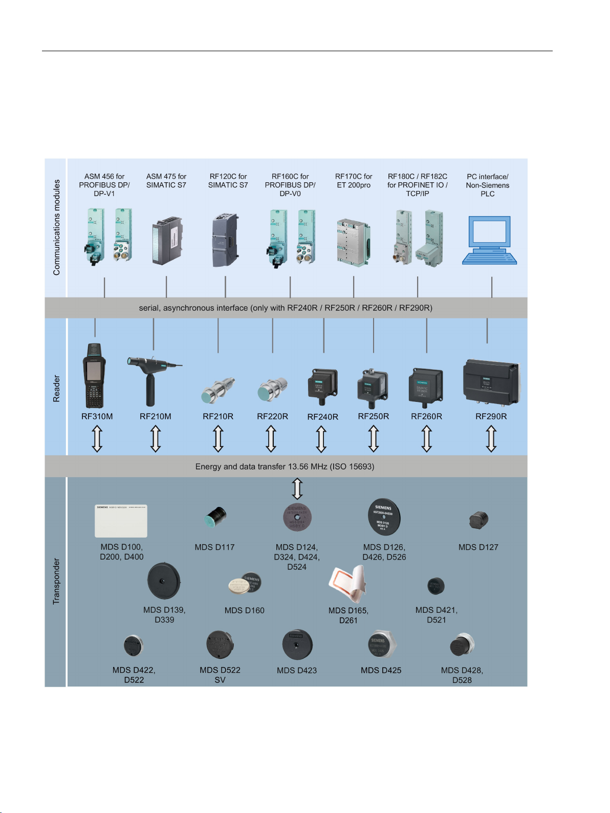
RF200 system components
3.1 RFID components and their function
Figure 3-1 RF200 system overview
SIMATIC RF200
20 System Manual, 07/2015, J31069-D0227-U001-A9-7618
Page 21

System overview
Transponder
RF210R/
RF210M
RF220R
RF240R
RF250R
with
RF260R
RF290R 4)
RF310M
ANT 3
ANT 8
ANT 12
ANT 18
ANT 30
MDS
D100
MDS
D117
MDS
D124
MDS
D126
MDS
D127
MDS
D139 1)
MDS
D160 2)
MDS
D165
MDS
D200
MDS
D261
MDS
D324
MDS
D339
MDS
D400
MDS
D421
MDS
D422
MDS
D423
MDS
D424
MDS
D425
MDS
D426
MDS
D428
MDS
D460
MDS
D521
3.1 RFID components and their function
Table 3- 1 Possible reader-transponder combinations
-- ○ ✓ ○ -- -- -- ○ ✓ ✓ ✓
○ -- -- -- ✓ ✓ -- -- -- -- ✓
✓ ✓ ✓ ✓ -- -- ✓ ✓ ✓ ✓ ✓
-- ✓ ✓ ✓ -- -- -- ✓ ✓ ✓ ✓
6)
✓ -- -- -- ✓ ✓ -- -- -- -- ✓
-- ○ ○ ○ -- -- -- ○ ✓ ✓ ✓
✓ ✓ ✓ ✓ -- ✓ ✓ ✓ ✓ ✓ ✓
-- ○ ✓ ○ -- -- -- ○ ✓ ✓ ✓
-- ○ ✓ ○ -- -- -- ○ ✓ ✓ ✓
-- ○ ✓ ○ -- -- -- ○ ✓ ✓ ✓
✓ ✓ ✓ ✓ -- ○ ✓ ✓ ✓ ✓ ✓
-- ○ ○ ○ -- -- -- ○ ✓ ✓ ✓
-- -- ✓ ○ -- -- -- ○ ✓ ✓ ✓
✓ ○ -- -- ✓ ✓ ✓ -- -- -- ✓
✓ ✓ ✓ ✓ -- ✓ ✓ ✓ -- -- ✓
✓ ✓ ✓ ✓ -- -- ✓ ✓ ✓ -- ✓
6)
6)
6)
✓ ✓ ✓ ✓ -- -- ✓ ✓ ✓ ✓ ✓
✓ ✓ ✓ ✓ -- ✓ ✓ ✓ -- -- ✓
-- ✓ ✓ ✓ -- -- -- ✓ ✓ ✓ ✓
✓ ✓ ✓ ✓ -- ✓ ✓ ✓ ✓ -- ✓
✓ ✓ ✓ ✓ -- ✓ ✓ ✓ ✓ ○ / ✓ 5) ✓
✓ ○ -- -- ✓ ✓ ✓ -- -- -- ✓
SIMATIC RF200
System Manual, 07/2015, J31069-D0227-U001-A9-7618
6)
21
Page 22

System overview
Transponder
RF210R/
RF210M
RF220R
RF240R
RF250R
with
RF260R
RF290R 4)
RF310M
ANT 3
ANT 8
ANT 12
ANT 18
ANT 30
MDS
D522
MDS
D524
MDS
D526
MDS
D528
1)
2)
3)
4)
5)
6)
only in conjunction with RF310M for external antennas (6GT2803-1AC10)
✓
Combination possible
--
Combination not possible
Combination possible, but not recommended
3.1 RFID components and their function
3)
✓ ✓ ✓ ✓ -- -- ✓ ✓ ✓ ✓ ✓
-- ✓ ✓ ✓ -- -- -- ✓ ✓ ✓ ✓
✓ ✓ ✓ ✓ -- ✓ ✓ ✓ ✓ -- ✓
only with the article number 6GT2600-0AA10
only with the article number 6GT2600-0AB10
The transponder MDS D522 special variant has the same compatibility as the transponder MDS D522.
in conjunction with ANT D5, D6 or D10
combination recommended only in conjunction with ANT D5.
✓ ✓ ✓ ✓ -- ✓ ✓ ✓ -- -- ✓
○
6)
SIMATIC RF200
22 System Manual, 07/2015, J31069-D0227-U001-A9-7618
Page 23

System overview
3.2
Overview of transponders
Overview of typical areas of application of ISO transponders for RF200
Transponder
Area of application
ranges are achieved in combination with the SIMATIC RF260R reader.
tool identification.
MDS D124
Application areas in factory automation (e.g. small paintshops to 180°C).
logistics; can also be deployed in harsh conditions.
identification.
and distribution logistics, right up to product identification
and distribution logistics, right up to product identification.
and distribution logistics, right up to product identification.
For typical areas of application, see "MDS D139".
3.2 Overview of transponders
MDS D100 From simple identification such as electronic barcode replacement or supplementation, through ware-
house and distribution logistics, right up to product identification. With this transponder, the maximum
MDS D117 Very compact data carrier that can be cemented into objects where precise positioning is necessary. e.g.
MDS D126 Compact and rugged ISO transponder; suitable for identification of transport units in production-related
MDS D127 Very compact data carrier that can be screwed into areas where precise positioning is necessary. e.g. tool
MDS D139 1) Applications in production automation with high temperature demands (up to +220 °C).
Typical application areas:
• Paintshops and their preparatory treatments
• Primer coat, electrolytic dip area, cataphoresis with the associated drying furnaces
• Top coat area with drying furnaces
• Washing areas at temperatures > 85 °C
• Other applications with higher temperatures
MDS D160 2) Typical applications are, for example:
• Rented work clothing
• Hotel laundry
• Surgical textiles
• Hospital clothing
• Dirt collection mats
• Clothing for nursing homes/hostels
• Assembly lines with very small workpiece holders
MDS D165 Smart label (self-adhesive label)
From simple identification such as electronic barcode replacement/supplementation, through warehouse
MDS D200 From simple identification such as electronic barcode replacement/supplementation, through warehouse
MDS D261 Smart label (self-adhesive label)
The design of the transponder (self-adhesive label) permits a variety of designs in order to ensure optimum dimensioning for the widest variety of applications.
From simple identification such as electronic barcode replacement/supplementation, through warehouse
MDS D324 Production and distribution logistics as well as in assembly and production lines
MDS D339 Applications in production automation with high temperature demands (up to +220 °C).
SIMATIC RF200
System Manual, 07/2015, J31069-D0227-U001-A9-7618
23
Page 24

System overview
Transponder
Area of application
tion logistics right through to product identification.
workpiece holders
MDS D422
Identification of metallic workpiece holders, workpieces or containers
MDS D424
Production and distribution logistics as well as in assembly and production lines
and workpiece holders
logistics; can also be deployed in harsh conditions
Use in assembly and production lines in the powertrain sector
MDS D460
Assembly lines with very small workpiece holders
carriers and exact positioning are required, e.g. tool identification, workpiece holders.
MDS D522
Identification of metallic workpiece holders, workpieces or containers
ants
logistics; can also be deployed in harsh environmental conditions
Use in assembly and production lines in the powertrain sector
1)
2)
Only with the MLFB 6GT2600-0AB10
Overview of the memory sizes of the ISO transponders for RF200
Transponder
Memory size
MDS D1xx
112 bytes of EEPROM
MDS D2xx
256 bytes of EEPROM
MDS D3xx
992 bytes of EEPROM
MDS D4xx
2000 bytes FRAM
MDS D5xx
8192 bytes FRAM
3.2 Overview of transponders
MDS D400 Simple identification such as electronic barcode replacement/supplements, from warehouse and distribu-
MDS D421 The MDS D421 is designed for tool coding according to DIN 69873.
It can be used wherever small data carriers and exact positioning are required, e.g. tool identification,
MDS D423 Identification of metallic workpiece holders, workpieces or containers, production automation
MDS D425 Compact and rugged ISO transponder; suitable for screw mounting.
Use in assembly and production lines in the powertrain sector; ideal for mounting on motors, gearboxes,
MDS D426 Compact and rugged ISO transponder; suitable for identification of transport units in production-related
MDS D428 Compact and rugged ISO transponder; suitable for screw mounting
MDS D521 The MDS D521 is constructed for tool coding according to DIN 69873. It can be used wherever small data
MDS D522
If Identification of metallic workpiece holders or workpieces
Special vari-
MDS D524 Production and distribution logistics as well as in assembly and production lines
MDS D526 Compact and rugged ISO transponder; suitable for identification of transport units in production-related
MDS D528 Compact and rugged ISO transponder; suitable for screw mounting
Only with the MLFB 6GT2600-0AA10
SIMATIC RF200
24 System Manual, 07/2015, J31069-D0227-U001-A9-7618
Page 25

4
4.1
Fundamentals of application planning
4.1.1
Selection criteria for SIMATIC RF200 components
4.1.2
Transmission window and read/write distance
Assess your application according to the following criteria, in order to choose the right
SIMATIC RF200 components:
● Static or dynamic data transfer
● Data volume to be transferred
● Speed in case of dynamic transfer
● Ambient conditions such as relative humidity, temperature, chemical impacts, etc.
The reader generates an inductive alternating field. The field is strongest close to the reader;
however, a read/write distance of "zero" between reader and transponder is not
recommended.
The strength of the field decreases in proportion to the distance from the reader. The
distribution of the field depends on the structure and geometry of the antennas in the reader
and transponder
A prerequisite for the function of the transponder is a minimum field strength at the
transponder, which is still barely achieved at distance S
from the reader.
g
SIMATIC RF200
System Manual, 07/2015, J31069-D0227-U001-A9-7618
25
Page 26
RF200 system planning
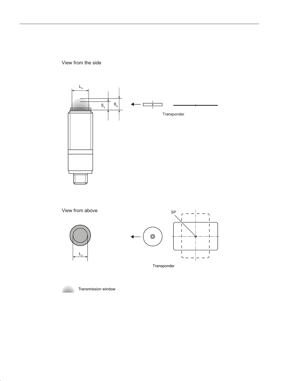
Sa
Operating distance between transponder and reader
sponder, at which the transmission can still function under normal conditions)
L
Diameter of a transmission window
SP
Intersection of the axes of symmetry of the transponder
4.1 Fundamentals of application planning
The picture below shows the transmission window of the SIMATIC RF210R and
SIMATIC RF220R readers between transponder and reader:
Sg Limit distance (maximum clear distance between upper surface of the reader and the tran-
Figure 4-1 RF210R/RF220R transmission window
SIMATIC RF200
26 System Manual, 07/2015, J31069-D0227-U001-A9-7618
Page 27
RF200 system planning
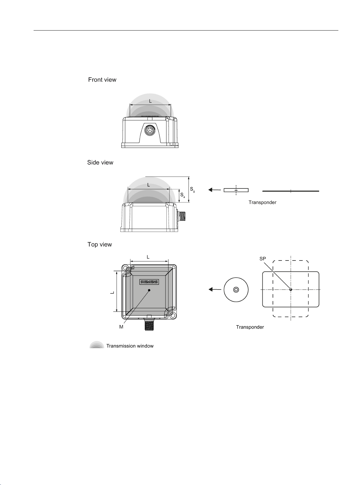
Sa
Operating distance between transponder and reader
sponder, at which the transmission can still function under normal conditions)
L
Length of a transmission window
M
Field centerpoint
4.1 Fundamentals of application planning
The figure below shows the transmission window of the SIMATIC RF240R and SIMATIC
RF260R readers between transponder and reader:
Sg Limit distance (maximum clear distance between upper surface of the reader and the tran-
Figure 4-2 RF240R/RF260R transmission window
The transponder can be used as soon as the intersection (SP) of the transponder enters the
area of the transmission window.
SIMATIC RF200
System Manual, 07/2015, J31069-D0227-U001-A9-7618
27
Page 28

RF200 system planning
4.1.3
Width of the transmission window
Determining the width of the transmission window
B:
Width of the transmission window
L:
Length of the transmission window
Tracking tolerances
4.1 Fundamentals of application planning
From the diagrams above, it can also be seen that operation is possible within the area
and Sg. The active operating area reduces as the distance increases, and
a
. Only static mode should thus be used in the area
g
and Sg.
a
between S
shrinks to a single point at distance S
between S
The following approximation formula can be used for practical applications:
The width of the transmission window (B) is particularly important for the mechanical tracking
tolerance. The formula for the dwell time is valid without restriction when B is observed.
SIMATIC RF200
28 System Manual, 07/2015, J31069-D0227-U001-A9-7618
Page 29
RF200 system planning
4.1.4
Impact of secondary fields
①
Main field
②
Secondary field
4.1 Fundamentals of application planning
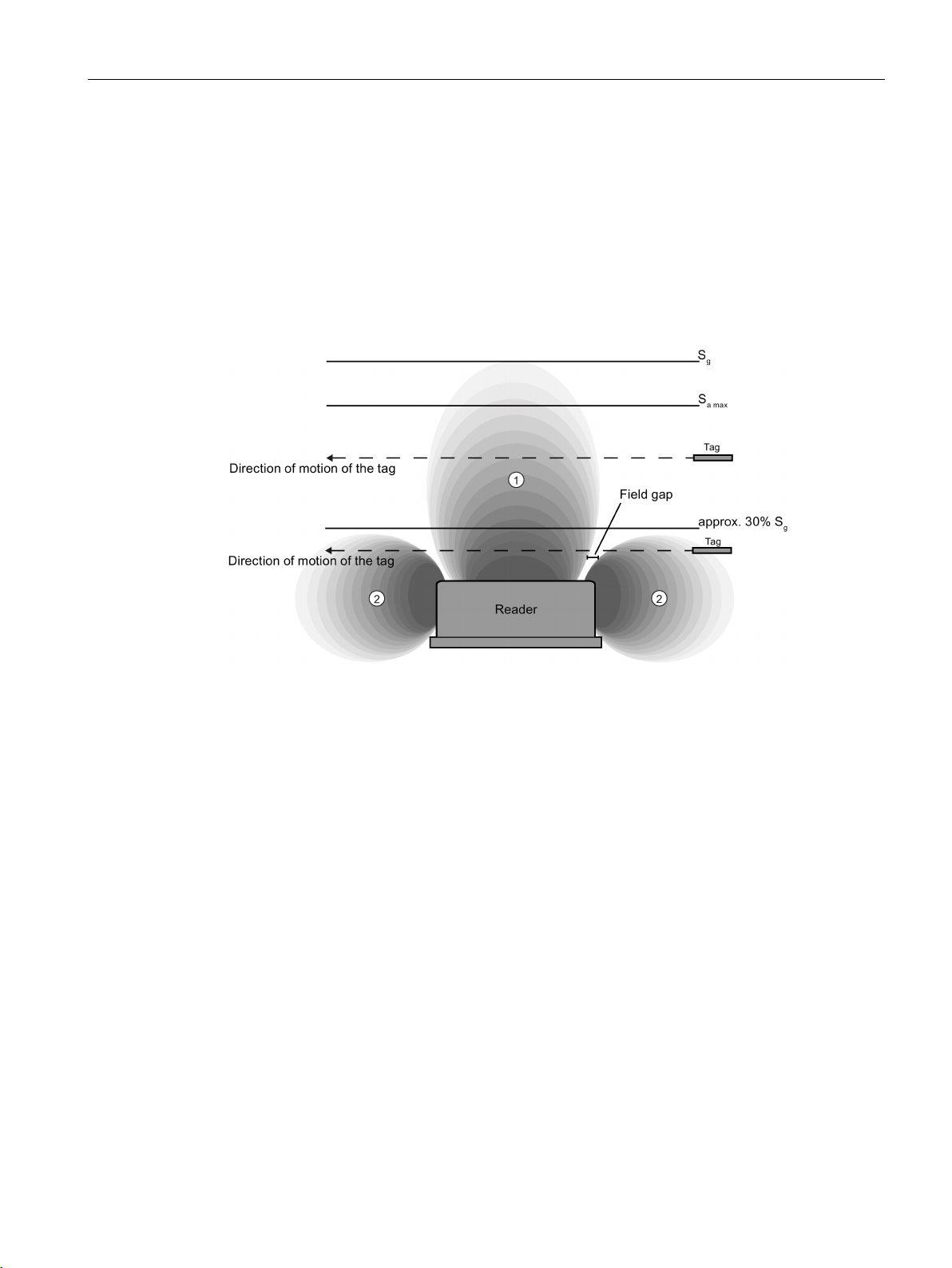
Secondary fields in the range from 0 mm to 30% of the limit distance (Sg) generally always
exist.
They should, however, only be used during configuration in exceptional cases, since the
read/write distances are very limited. Exact details of the secondary field geometry cannot be
given, since these values depend heavily on the operating distance and the application.
When working in dynamic mode, remember that during the transition from the secondary
field to the main field the presence of the tag is lost temporarily. It is therefore advisable to
select a distance > 30 % of S
.
g
Figure 4-3 Gap in the field resulting from secondary fields
SIMATIC RF200
System Manual, 07/2015, J31069-D0227-U001-A9-7618
29
Page 30
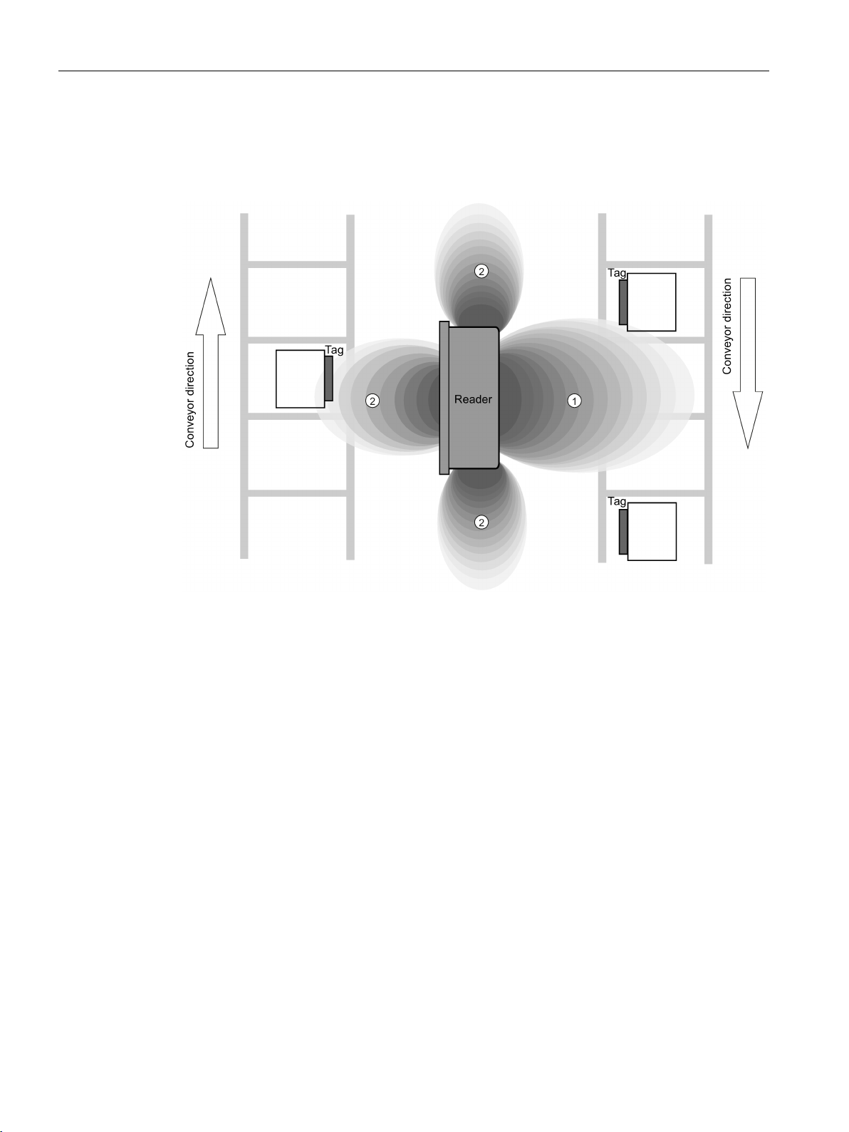
RF200 system planning
Secondary fields without shielding
①
Main field
②
Secondary field
4.1 Fundamentals of application planning
The following graphic shows typical primary and secondary fields, if no shielding measures
are taken.
Figure 4-4 Secondary field without shielding
In this arrangement, the reader can also read tags via the secondary field. Shielding is
required in order to prevent unwanted reading via the secondary field, as shown and
described in the following.
SIMATIC RF200
30 System Manual, 07/2015, J31069-D0227-U001-A9-7618
Page 31
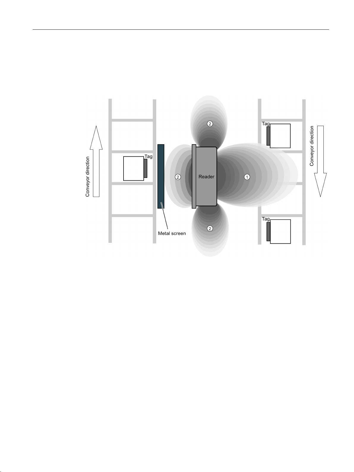
RF200 system planning
Secondary fields with shielding
①
Main field
②
Secondary field
4.1 Fundamentals of application planning
The following graphic shows typical primary and secondary fields, with metal shielding this
time.
The metal shielding prevents the reader from detecting tags via the secondary field.
Figure 4-5 Secondary field with shielding
SIMATIC RF200
System Manual, 07/2015, J31069-D0227-U001-A9-7618
31
Page 32
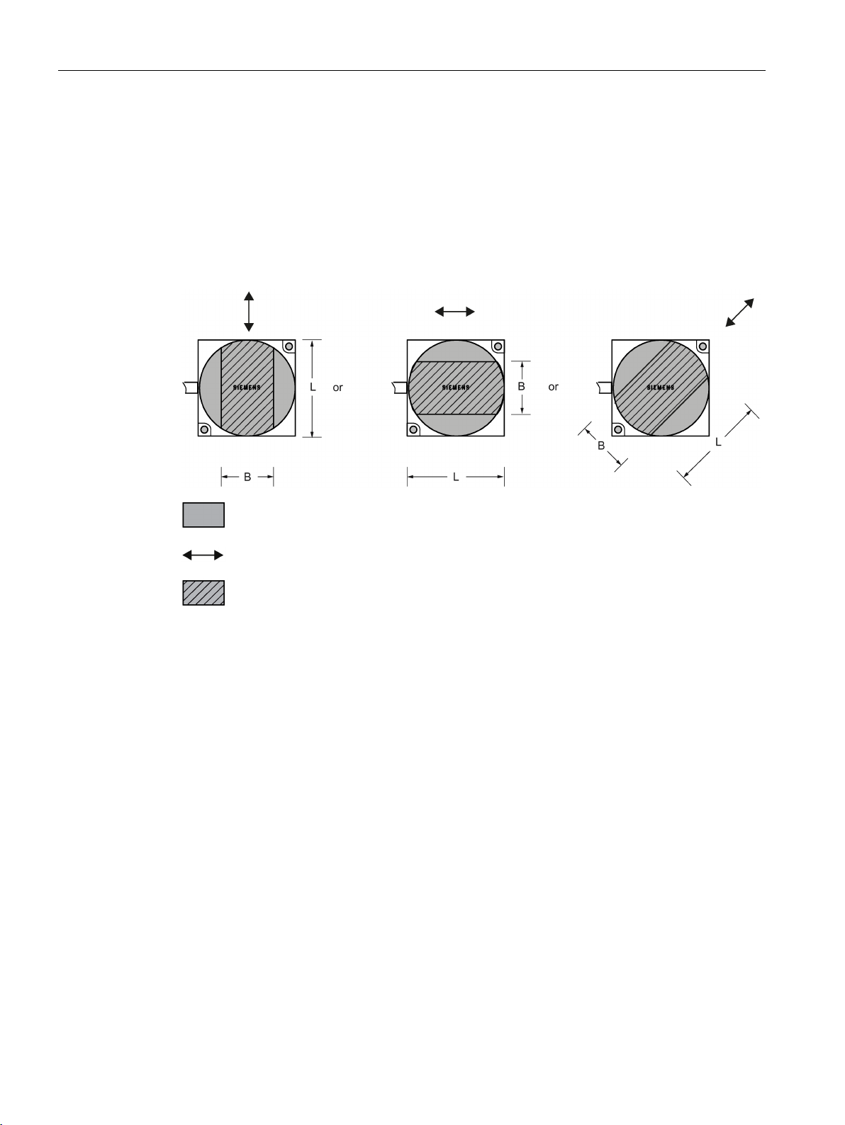
RF200 system planning
4.1.5
Permissible directions of motion of the transponder
Detection area and direction of motion of the transponder
4.1 Fundamentals of application planning
The transponder and reader have no polarization axis, i.e. the transponder can come in from
any direction, assume any position as parallel as possible to the reader, and cross the
transmission window. The figure below shows the active area for various directions of
transponder motion:
Transmission window
Figure 4-6 Detection areas of the reader for different directions of transponder motion
Direction of motion of the transponder
Detection area L x W
SIMATIC RF200
32 System Manual, 07/2015, J31069-D0227-U001-A9-7618
Page 33
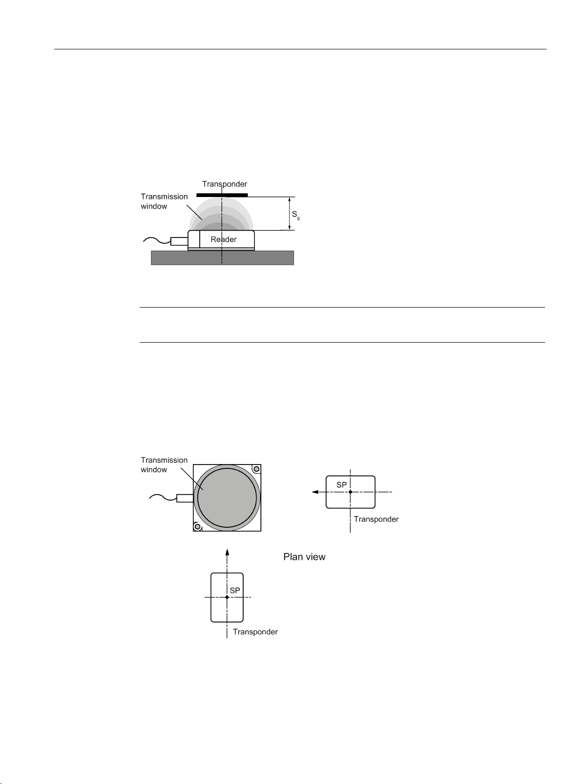
RF200 system planning
4.1.6
Operation in static and dynamic mode
Operation in static mode
Note
Note that in a metallic environment the values for
Operation in dynamic mode
4.1 Fundamentals of application planning
If working in static mode, the transponder can be operated up to the limit distance (Sg). The
transponder must then be positioned exactly over the reader:
Figure 4-7 Operation in static mode
When working in dynamic mode, the transponder moves past the reader. The transponder
can be used as soon as the intersection (SP) of the transponder enters the circle of the
transmission window. In dynamic mode, the operating distance (S
[Operating distances, see Chapter Field data of transponders and readers (Page 36)]
the limit distance are reduced.
) is of primary importance.
a
Figure 4-8 Operation in dynamic mode
SIMATIC RF200
System Manual, 07/2015, J31069-D0227-U001-A9-7618
33
Page 34

RF200 system planning
4.1.7
Dwell time of the transponder
tV:
Dwell time of the transponder
L: Length of the transmission window
v
:
Speed of the transponder (tag) in dynamic mode
0,8: Constant factor used to compensate for temperature impacts and production tole
ances
tV::
Dwell time of the data memory within the field of the reader
tK:
Communication time between transponder and communication module
4.1 Fundamentals of application planning
The dwell time is the time in which the transponder remains within the transmission window
of a reader. The reader can exchange data with the transponder during this time.
The dwell time is calculated thus:
Tag
r-
The dwell time can be of any duration in static mode. The dwell time must be sufficiently long
to allow communication with the transponder.
The dwell time is defined by the system environment in dynamic mode. The volume of data
to be transferred must be matched to the dwell time or vice versa. In general:
SIMATIC RF200
34 System Manual, 07/2015, J31069-D0227-U001-A9-7618
Page 35
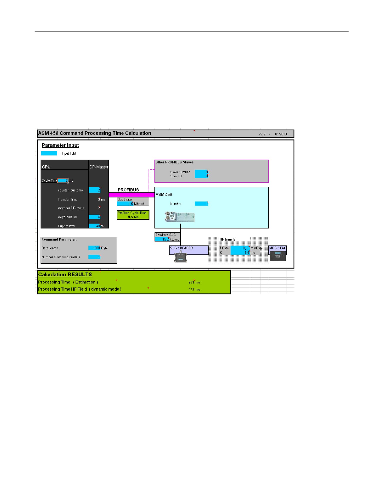
RF200 system planning
4.1.8
Communication between communication module, reader and transponder
Aids for calculating the data transmission times
4.1 Fundamentals of application planning
User-friendly calculation tools are available for the communications modules ASM 456,
RF160C, RF170C and RF180C to calculate data transfer times. The calculation tools can be
found on the DVD "RFID Systems Software & Documentation", article number 6GT20802AA20.
Figure 4-9 User interface of the calculation tool for command processing time
SIMATIC RF200
System Manual, 07/2015, J31069-D0227-U001-A9-7618
35
Page 36
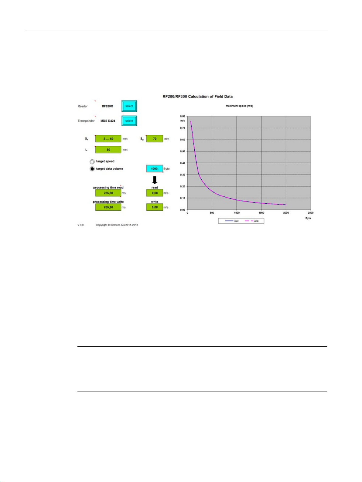
RF200 system planning
Aids for calculating the field data
4.2
Field data of transponders and readers
Tolerances of ±20 % are permitted due to production or temperature
conditions.
Note
Transmission gaps
I
center of the field. Communication with the transponder is not possible in the transmission
gap.
4.2 Field data of transponders and readers
You will also find a tool for calculating field data on the DVD "RFID Systems, Software &
Documentation". Using this tool, among other things you can calculate the operating
distance (S
), limit distance (Sg) and transmission window (L).
a
Figure 4-10 User interface of the calculation tool for field data acquisition
The following tables show the field data for all SIMATIC RF200 components of transponders
and readers. This makes the correct selection of a transponder and reader particularly easy.
All the technical specifications listed are typical data and are applicable for an ambient
temperature between 0 °C and +50 °C, a supply voltage between 22 and 27 VDC and a
metal-free environment.
If the entire voltage range at the reader of 20 VDC to 30 VDC and/or the entire temperature
range of transponders and readers is used, the field data is subject to further tolerances.
f the minimum operating distance (Sa) is not observed, a transmission gap can occur in the
SIMATIC RF200
36 System Manual, 07/2015, J31069-D0227-U001-A9-7618
Page 37

RF200 system planning
4.2.1
Field data
Length of the transmis-
sion window (Ld)
Operating distance (Sa)
Limit distance (Sg)
MDS D124
25
1 ... 18
20
MDS D127
MDS D160
20
1 ... 10
12
MDS D324
20
1 ... 8
9
MDS D421
5
0 ... 3
4
MDS D422 8 1 ... 9
10
MDS D423
20
2 ... 10
12
MDS D424
24
1 ... 16
18
MDS D425
12
1 ... 6
7
MDS D428
20
1 ... 10
11
MDS D460 8 1 … 8
9
MDS D521 5 0 ... 3
4
MDS D522 8 1 ... 8
9
MDS D522
Special variants
MDS D524
20
1 ... 15
17
MDS D528
15
1 ... 10
11
1)
All dimensions in mm.
Length of the transmis-
sion window (Ld)
Operating distance (Sa)
Limit distance (Sg)
MDS D124
35
1 ... 28
31
MDS D126
45
2 ... 30
35
MDS D160
20
1 ... 20
22
MDS D324
MDS D422
18
1 ... 12
14
MDS D423
MDS D424
30
2 ... 25
29
MDS D425
20
1 ... 11
13
MDS D426
40
2 ... 25
30
MDS D428
25
1 ... 18
21
MDS D460
25
1 ... 18
20
4.2 Field data of transponders and readers
The limit distances (Sg) and operating distances (Sa) along with the length of the
transmission window for each reader-transponder combination are listed in the tables below.
Table 4- 1 SIMATIC RF210R field data
1)
3 0 ... 2 2
The transponder is only suitable for static mode.
Table 4- 2 SIMATIC RF220R field data
30 2 ... 21 25
30 2 ...24 28
8 1 ... 8 9
SIMATIC RF200
System Manual, 07/2015, J31069-D0227-U001-A9-7618
37
Page 38

RF200 system planning
Length of the transmis-
sion window (Ld)
Operating distance (Sa)
Limit distance (Sg)
MDS D522
15
1 ... 10
12
MDS D522
Special variants
MDS D524
25
2 ... 22
25
MDS D526
MDS D528
20
1 ... 15
20
All dimensions in mm.
Length of the transmis-
sion window (L)
Operating distance (Sa)
Limit distance (Sg)
MDS D100
100
2 ... 84
95
MDS D124
65
2 ... 53
60
MDS D126
80
2 ... 57
65
MDS D160
50
1 ... 33
37
MDS D165
105
2 ... 80
94
MDS D200
90
2 ... 69
78
MDS D261
70
2 ... 60
70
MDS D324
55
1 ... 36
40
MDS D400
95
2 ... 80
90
MDS D422
25
1 ... 12
15
MDS D423
45
2 ... 35
40
MDS D424
75
1 ... 47
53
MDS D425
30
1 ... 15
17
MDS D426
65
2 ... 45
55
MDS D428
MDS D460
50
1 ... 30
34
MDS D522
MDS D522
Special variants
MDS D524
60
1 ... 45
55
MDS D526
60
2 ... 45
55
MDS D528
40
1 ... 30
35
All dimensions in mm.
4.2 Field data of transponders and readers
15 1 ... 10 12
30 2 ... 25 30
Table 4- 3 SIMATIC RF240R field data
SIMATIC RF200
38 System Manual, 07/2015, J31069-D0227-U001-A9-7618
50 1 ... 30 34
20 1 ... 10 12
20 1 ... 10 12
Page 39

RF200 system planning
Length of the transmis-
sion window (Ld)
Operating distance (Sa)
Limit distance (Sg)
MDS D124
40
1 ... 35
48
MDS D126
MDS D160
24
1 ... 23
30
MDS D324
32
1 ... 22
35
MDS D422
27
0 ... 12
15
MDS D423
30
2 ... 18
26
MDS D424
37
0 ... 34
48
MDS D425
22
1 ... 12
20
MDS D426
65
0 ... 44
58
MDS D428
30
1 ... 20
32
MDS D460
24
1 ... 21
27
MDS D522
20
1 ... 12
15
MDS D522
Special variants
MDS D524
35
1 ... 35
40
MDS D526
45
2 ... 35
45
MDS D528
25
1 ... 20
25
All dimensions in mm.
Length of the transmis-
sion window (Ld)
Operating distance (Sa)
Limit distance (Sg)
MDS D117 2 0 ... 2
3
MDS D127 3 0 ... 3
4
MDS D421 3 0 ... 3
4
MDS D521
All dimensions in mm.
Length of the transmis-
sion window (Ld)
Operating distance (Sa)
Limit distance (Sg)
MDS D117 3 0 ... 3
4
MDS D127 4 0 ... 4
5
MDS D160
18
0 ... 12
17
MDS D421
10
0 ... 3
4
MDS D422
22
0 ... 7
10
MDS D425
12
0 ... 8
10
4.2 Field data of transponders and readers
Table 4- 4 Field data SIMATIC RF250R, with ANT 3
65 0 ... 47 60
20 1 ... 12 15
Table 4- 5 Field data SIMATIC RF250R, with ANT 8
3 0 ... 3 4
Table 4- 6 Field data SIMATIC RF250R, with ANT 12
SIMATIC RF200
System Manual, 07/2015, J31069-D0227-U001-A9-7618
39
Page 40

RF200 system planning
Length of the transmis-
sion window (Ld)
Operating distance (Sa)
Limit distance (Sg)
MDS D428
18
1 ... 8
12
MDS D460
MDS D521 5 0 ... 3
4
MDS D522
10
1 ... 7
9
MDS D522
Special variants
MDS D528
15
1 ... 8
12
All dimensions in mm.
Length of the transmis-
sion window (Ld)
Operating distance (Sa)
Limit distance (Sg)
MDS D124
26
0 ... 24
37
MDS D160
22
1 ... 18
26
MDS D324
30
1 ... 18
27
MDS D421
16
0 ... 3
4
MDS D422
24
1 ... 8
14
MDS D423
21
1 ... 15
18
MDS D424
26
1 ... 27
36
MDS D425
19
1 ... 11
16
MDS D428
19
1 ... 18
25
MDS D460
19
1 ... 17
21
MDS D521 6 0 ... 4
5
MDS D522
15
1 ... 10
12
MDS D522
Special variants
MDS D524
30
1 ... 25
30
MDS D528
20
1 ... 15
20
All dimensions in mm.
Length of the transmis-
sion window (Ld)
Operating distance (Sa)
Limit distance (Sg)
MDS D124
40
1 ... 35
48
MDS D126
65
0 ... 47
60
MDS D160
24
1 ... 23
30
MDS D324
32
1 ... 22
35
MDS D422
27
0 ... 12
15
MDS D423
30
2 ... 18
26
4.2 Field data of transponders and readers
16 1 ... 10 14
10 1 ... 7 9
Table 4- 7 Field data SIMATIC RF250R, with ANT 18
SIMATIC RF200
40 System Manual, 07/2015, J31069-D0227-U001-A9-7618
15 1 ... 10 12
Table 4- 8 Field data SIMATIC RF250R, with ANT 30
Page 41

RF200 system planning
Length of the transmis-
sion window (Ld)
Operating distance (Sa)
Limit distance (Sg)
MDS D424
37
0 ... 34
48
MDS D425
MDS D426
65
0 ... 44
58
MDS D428
30
1 ... 20
32
MDS D460
24
1 ... 21
27
MDS D522
20
1 ... 12
15
MDS D522
Special variants
MDS D524
35
1 ... 35
40
MDS D526
60
2 ... 35
45
MDS D528
25
1 ... 20
25
All dimensions in mm.
Length of the transmis-
sion window (L)
Operating distance (Sa)
Limit distance (Sg)
MDS D100
120
2 ... 110
130
MDS D124
80
2 ... 80
85
MDS D126
110
2 ... 75
100
MDS D139
120
2 ... 80
110
MDS D160
60
2 ... 40
45
MDS D165
120
2 ... 120
135
MDS D200
120
2 ... 100
120
MDS D261
80
2 ... 75
90
MDS D324
80
2 ... 60
70
MDS D339
MDS D400
140
2 ... 110
140
MDS D423
MDS D424
80
2 ... 60
70
MDS D426
75
2 ... 70
85
MDS D428
50
2 ... 40
45
MDS D460
50
2 ... 40
45
MDS D524
70
2 ... 60
70
MDS D526
80
2 ... 70
85
MDS D528
50
2 ... 35
40
All dimensions in mm.
4.2 Field data of transponders and readers
22 1 ... 12 20
20 1 ... 12 15
Table 4- 9 SIMATIC RF260R field data
SIMATIC RF200
System Manual, 07/2015, J31069-D0227-U001-A9-7618
110 5 ... 65 80
55 2 ... 40 45
41
Page 42

RF200 system planning
Length of the transmis-
sion window (L)
Operating distance (Sa)
Limit distance (Sg)
MDS D100
320
0 ... 400
500
MDS D124
MDS D126
320
0 ... 350
400
MDS D139
320
0 ... 400
500
MDS D160
300
0 ... 130
180
MDS D165
320
0 ... 350
450
MDS D200
320
0 ... 400
500
MDS D261
320
0 ... 300
400
MDS D324
300
0 ... 200
280
MDS D339
320
0 ... 300
380
MDS D400
320
0 ... 400
500
MDS D424
300
0 ... 200
280
MDS D426
320
0 ... 300
350
MDS D460
300
0 ... 120
160
MDS D524
300
0 ... 200
280
MDS D526
320
0 ... 300
350
All dimensions in mm.
Length of the transmission
window (L)
Operating distance (Sa)
Limit distance (Sg)
X direction
Y direction
MDS D100
520
420
0 ... 550
650
MDS D124
500
400
0 ... 220
300
MDS D126
520
420
0 ... 400
500
MDS D139
520
420
0 ... 500
600
MDS D160
MDS D165
520
420
0 ... 400
500
MDS D200
MDS D261
520
420
0 ... 350
450
MDS D324
500
400
0 ... 200
280
MDS D339
520
420
0 ... 400
480
MDS D400
520
420
0 ... 500
650
MDS D424
500
400
0 ... 220
300
MDS D426
520
420
0 ... 350
400
MDS D524
500
400
0 ... 220
300
MDS D526
520
420
0 ... 350
400
All dimensions in mm.
4.2 Field data of transponders and readers
Table 4- 10 Field data SIMATIC RF290R, with ANT D5 (at 4 W)
300 0 ... 200 280
Table 4- 11 Field data SIMATIC RF290R, with ANT D6 (at 4 W)
500 400 0 ... 130 180
520 420 0 ... 500 600
SIMATIC RF200
42 System Manual, 07/2015, J31069-D0227-U001-A9-7618
Page 43

RF200 system planning
Length of the transmission
window (L)
Operating distance (Sa)
Limit distance (Sg)
X direction
Y direction
MDS D100
1050
350
0 ... 500
600
MDS D124
1000
300
0 ... 200
280
MDS D126
MDS D139
1050
350
0 ... 450
550
MDS D160
1000
300
0 ... 130
180
MDS D165
1050
350
0 ... 350
450
MDS D200
1050
350
0 ... 450
550
MDS D261
1050
350
0 ... 350
450
MDS D324
1000
300
0 ... 200
280
MDS D339
1050
350
0 ... 300
380
MDS D400
1050
350
0 ... 400
500
MDS D424
1000
300
0 ... 200
280
MDS D426
1050
350
0 ... 350
400
MDS D524
1000
300
0 ... 220
300
MDS D526
1050
350
0 ... 350
400
All dimensions in mm.
4.2 Field data of transponders and readers
Table 4- 12 Field data SIMATIC RF290R, with ANT D10 (at 4 W)
1050 350 0 ... 400 500
SIMATIC RF200
System Manual, 07/2015, J31069-D0227-U001-A9-7618
43
Page 44

RF200 system planning
4.2.2
Minimum clearances
Minimum distance from transponder to transponder
RF210R
RF220R
RF240R
RF260R
MDS D100
--
--
--
≥ 240
MDS D117
MDS D124
≥ 25
≥ 40
≥ 90
≥ 180
MDS D126
MDS D127
≥ 15
--
--
--
MDS D139
--
--
--
≥ 200
MDS D160
≥ 20
≥ 25
≥ 70
≥ 150
MDS D165
--
--
--
≥ 240
MDS D200
--
--
--
≥ 240
MDS D261
--
--
--
≥ 200
MDS D324
≥ 25
≥ 40
≥ 90
≥ 180
MDS D339
--
--
--
≥ 200
MDS D400
--
--
--
≥ 240
MDS D421
≥ 10
--
--
--
MDS D422
≥ 15
≥ 20
≥ 50
--
MDS D423
--
--
≥ 80
≥ 160
MDS D424
≥ 25
≥ 40
≥ 90
≥ 180
MDS D425
≥ 20
≥ 25
≥ 75
--
MDS D426
--
≥ 50
≥ 90
≥ 180
MDS D428
≥ 25
≥ 25
≥ 75
≥ 150
MDS D460
MDS D521
≥ 10
--
--
--
MDS D522
≥ 15
≥ 20
≥ 50
--
MDS D522
Special variants
MDS D524
MDS D526
--
≥ 50
≥ 90
≥ 180
MDS D528
≥ 25
≥ 25
≥ 75
≥ 150
All values are in mm, relative to the operating distance (S
between transponder edge and transponder edge
4.2 Field data of transponders and readers
The specified distances refer to a metal-free environment. For a metallic environment, the
specified minimum distances must be multiplied by a factor of 1.5.
Table 4- 13 Minimum clearances for transponders
≥ 15 -- -- --
-- ≥ 50 ≥ 100 ≥ 180
≥ 20 ≥ 25 ≥ 70 ≥ 150
≥ 25 ≥ 40 ≥ 90 ≥ 180
SIMATIC RF200
44 System Manual, 07/2015, J31069-D0227-U001-A9-7618
≥ 15 ≥ 20 ≥ 50 --
) between reader and transponder, and
a
Page 45

RF200 system planning
RF250R
1)
RF290R
2)
ANT 3
ANT 8
ANT 12
ANT 18
ANT 30
ANT D5
ANT D6
ANT D10
MDS D100
--
--
--
--
--
≥ 1000
≥ 1500
≥ 2000
MDS D117
--
≥ 30
≥ 50
--
--
--
--
--
MDS D124
MDS D126
≥ 100
--
--
--
≥ 100
≥ 1000
≥ 1500
≥ 2000
MDS D127
--
≥ 40
≥ 60
--
--
--
--
--
MDS D139
--
--
--
--
--
≥ 1000
≥ 1500
≥ 2000
MDS D160
≥ 100
--
≥ 60
≥ 80
≥ 100
≥ 800
≥ 1200
≥ 1800
MDS D165
--
--
--
--
--
≥ 1000
≥ 1500
≥ 2000
MDS D200
--
--
--
--
--
≥ 1000
≥ 1500
≥ 2000
MDS D261
--
--
--
--
--
≥ 1000
≥ 1500
≥ 2000
MDS D324
≥ 100
--
--
≥ 80
≥ 100
≥ 800
≥ 1200
≥ 1800
MDS D339
--
--
--
--
--
≥ 1000
≥ 1500
≥ 2000
MDS D400
--
--
--
--
--
≥ 1000
≥ 1500
≥ 2000
MDS D421
--
≥ 30
≥ 40
≥ 50
--
--
--
--
MDS D422
≥ 70
--
≥ 50
≥ 60
≥ 70
--
--
--
MDS D423
≥ 100
--
--
≥ 80
≥ 100
--
--
--
MDS D424
≥ 100
--
--
≥ 80
≥ 100
≥ 800
≥ 1200
≥ 1800
MDS D425
≥ 80
--
≥ 50
≥ 60
≥ 80
--
--
--
MDS D426
≥ 100
--
--
--
≥ 100
≥ 800
≥ 1200
≥ 1800
MDS D428
≥ 80
--
≥ 50
≥ 60
≥ 80
--
--
--
MDS D460
≥ 100
--
≥ 60
≥ 80
≥ 100
≥ 800
--
--
MDS D521
MDS D522
≥ 70
--
≥ 50
≥ 60
≥ 70
--
--
--
MDS D522
Special variants
MDS D524
≥ 100
--
--
≥ 80
≥ 100
≥ 800
≥ 1200
≥ 1800
MDS D526
≥ 100
--
--
--
≥ 100
≥ 800
≥ 1200
≥ 1800
MDS D528
≥ 80
--
≥ 50
≥ 60
≥ 80
--
--
--
1)
2)
All values are in mm, relative to the operating distance (S
between transponder edge and transponder edge
4.2 Field data of transponders and readers
Table 4- 14 Minimum clearances for transponders
≥ 100 -- -- ≥ 80 ≥ 100 ≥ 800 ≥ 1200 ≥ 1800
-- ≥ 30 ≥ 40 ≥ 50 -- -- -- --
≥ 70 -- ≥ 50 ≥ 60 ≥ 70 -- -- --
Depends on the connected antenna (ANT 3, 8, 12, 18 or 30).
Depends on the connected antenna (ANT D5, D6 or D10).
) between reader and transponder, and
a
SIMATIC RF200
System Manual, 07/2015, J31069-D0227-U001-A9-7618
45
Page 46

RF200 system planning
Minimum distance from reader to reader
RF210R to
RF210R
RF220R to
RF220R
RF240R to
RF240R
ANT x to ANT x
with RF250R
RF260R to
RF260R
ANT Dx to
ANT Dx
with RF290R
≥ 2000 mm
ANT 12: ≥ 60 mm
≥ 100 mm
All values are in mm
Note
Effect on inductive fields by not maintaining the minimum distances of the readers
If the values fall below those specified in the "minimum distance readers or antennas", there
is a risk of the function being affected by inductive fields. In this case, the data transfer time
would increase unpredictably or a command would be aborted with
Keeping to the values specified in the "Minimum distance readers or antennas" table is
therefore essential.
4.2 Field data of transponders and readers
Table 4- 15 Minimum distances to readers or antennas
≥ 60 mm ≥ 100 mm ≥ 120 mm ANT 3: ≥ 100 mm ≥ 150 mm ANT D5:
ANT 8: ≥ 50 mm ANT D10:
≥ 2000 mm
ANT 18: ≥ 80 mm
ANT 30:
an error.
If the specified minimum distance cannot be complied with due to the physical configuration,
the SET-ANT command can be used to activate and deactivate the HF field of the reader.
The application software must be used to ensure that only one reader is active (antenna is
switched on) at a time.
SIMATIC RF200
46 System Manual, 07/2015, J31069-D0227-U001-A9-7618
Page 47
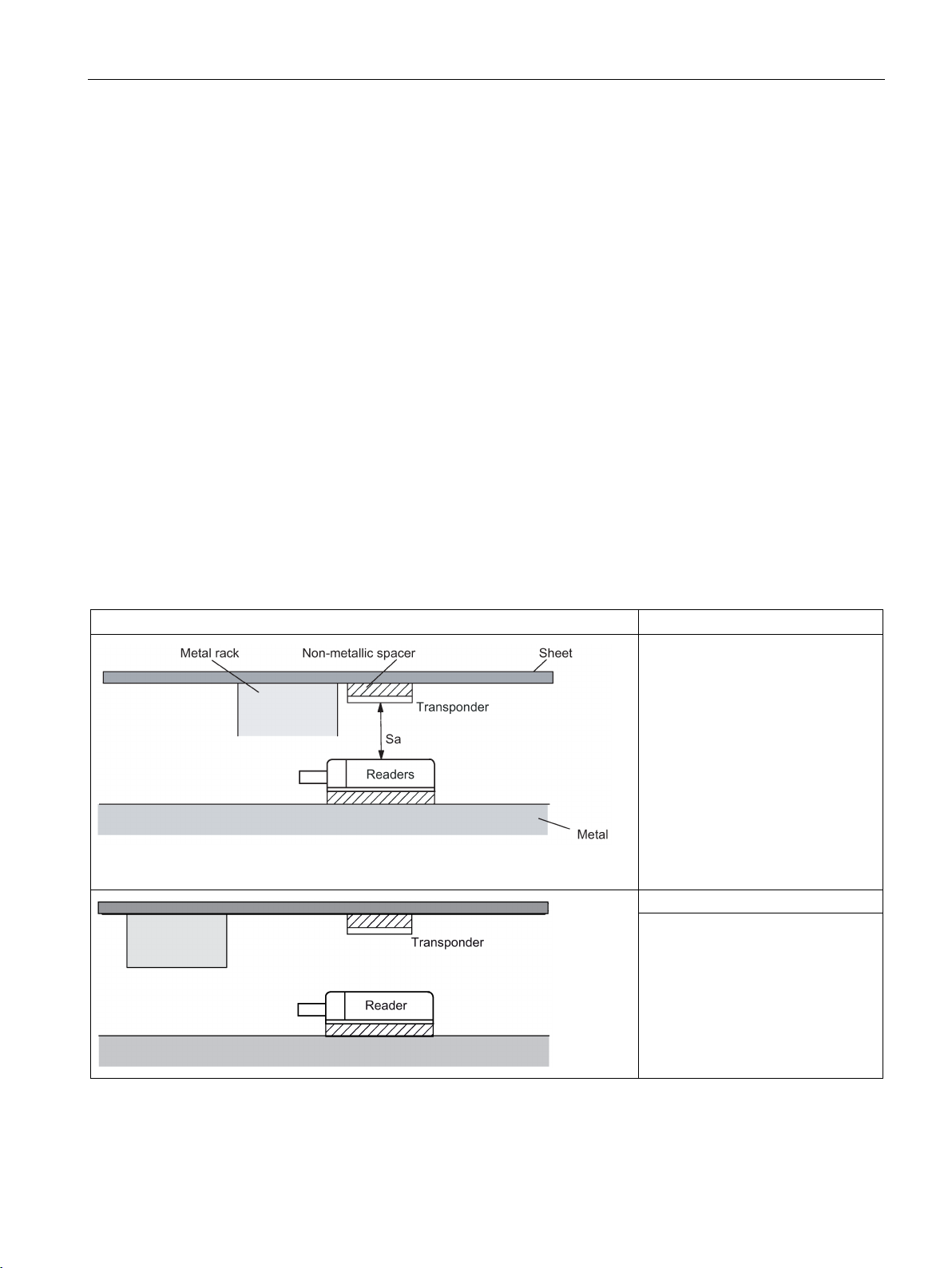
RF200 system planning
4.3
Installation guidelines
4.3.1
Overview
4.3.2
Reduction of interference due to metal
Interference due to metal rack
Problem
Remedy:
4.3 Installation guidelines
The transponder and reader complete with their antennas are inductive devices. Any type of
metal in the vicinity of these devices affects their functionality. Some points need to be
considered during planning and installation if the values described in the "Field data
(Page 37)" section are to retain their validity:
● Minimum spacing between two readers or their antennas
● Minimum distance between two adjacent data memories
● Metal-free area for flush-mounting of readers or their antennas and transponders in metal
● Mounting of multiple readers or their antennas on metal frames or racks
The following sections describe the impact on the operation of the RFID system when
mounted in the vicinity of metal.
A metal rack is located above the
transmission window of the reader.
This affects the entire field. In particular, the transmission window
between reader and transponder is
reduced.
The transmission window is no
longer affected if the transponder is
mounted differently.
SIMATIC RF200
System Manual, 07/2015, J31069-D0227-U001-A9-7618
47
Page 48
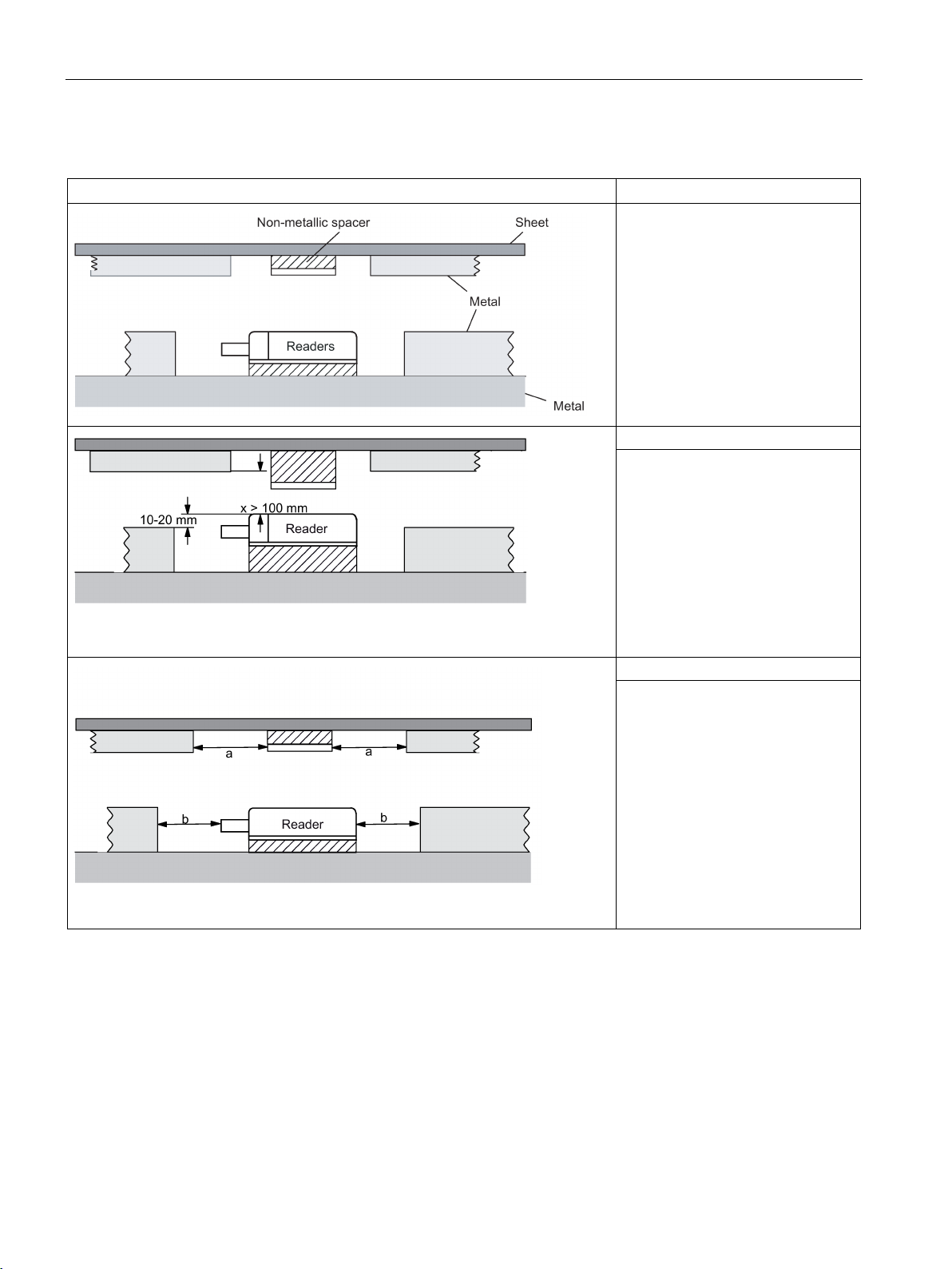
RF200 system planning
Flush-mounting
Flush-mounting of transponders and readers
Problem
Remedy:
affected by metal.)
Remedy:
4.3 Installation guidelines
Flush-mounting of transponders and
readers is possible in principle.
However, the size of the transmission window is significantly reduced.
The following measures can be
used to counteract the reduction of
the window:
Enlargement of the non-metallic
spacer below the transponder
and/or reader.
The transponder and/or reader are
10 to 20 mm higher than the metal
surround.
(The value x ≥ 100 mm is valid, for
example, for RF260R. It indicates
that, for a distance x ≥ 100 mm, the
reader can no longer be significantly
Increase the non-metallic distance
a, b.
The following rule of thumb can be
used:
• Increase a, b by a factor of 2 to 3
over the values specified for
metal-free areas
• Increasing a, b has a greater
effect for readers or transponders with a large limit distance
than for readers or transponders
with a small limit distance.
SIMATIC RF200
48 System Manual, 07/2015, J31069-D0227-U001-A9-7618
Page 49
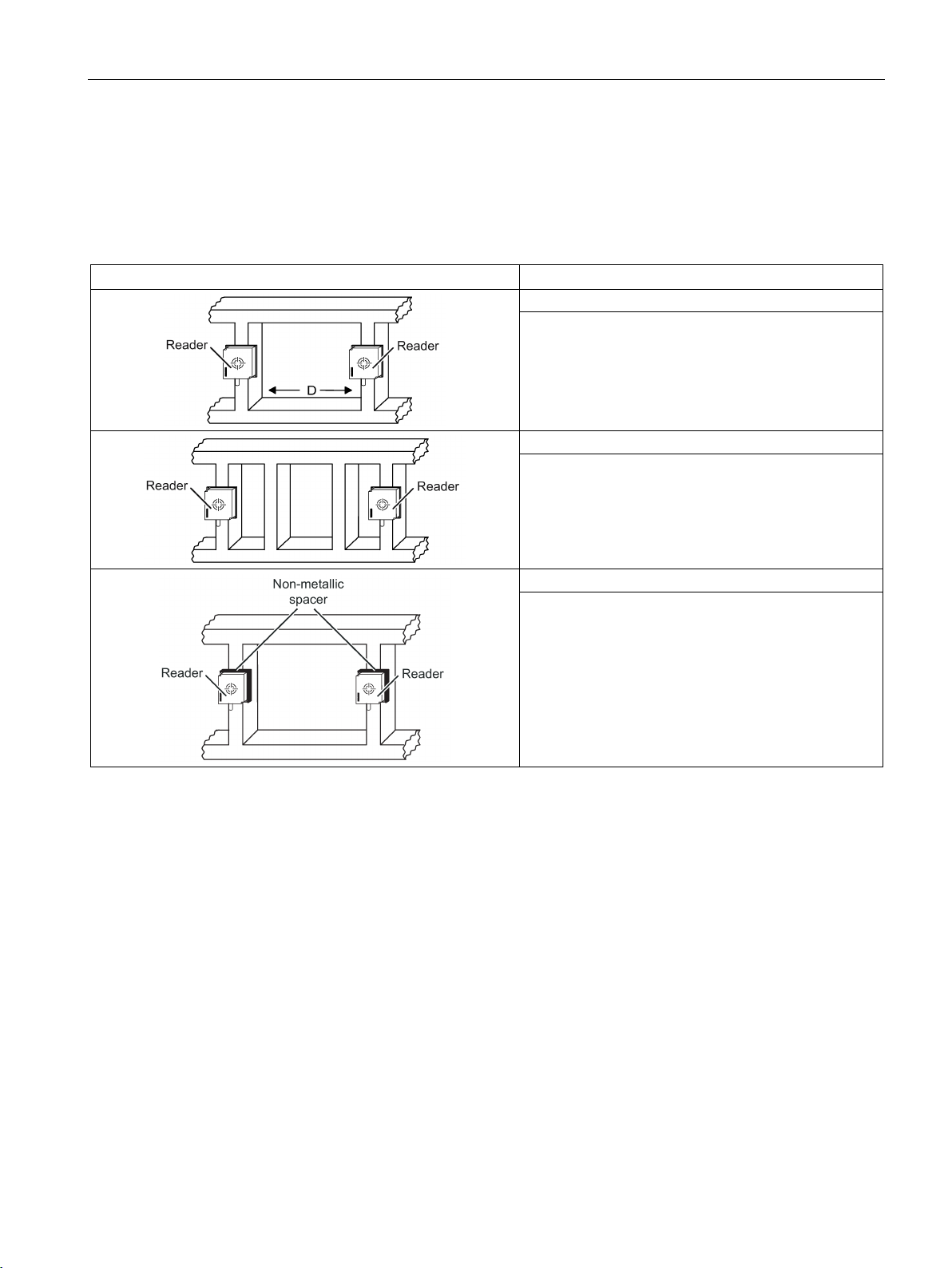
RF200 system planning
Mounting of several readers on metal frames or racks
Mounting of several readers on metal racks
Problem: Interaction between readers
Remedy
Remedy
Remedy
4.3.3
Effects of metal on different transponders and readers
Mounting different transponders and readers on metal or flush-mounting
4.3 Installation guidelines
Any reader mounted on metal couples part of the field to the metal frame. There is normally
no interaction as long as the minimum distance D and metal-free areas a, b are maintained.
However, interaction may take place if an iron frame is positioned unfavorably. Longer data
transfer times or sporadic error messages at the communication module are the result.
Increase the distance D between the two readers.
Introduce one or more iron struts in order to shortcircuit the stray fields.
Insert a non-metallic spacer of 20 to 40 millimeter
thickness between the reader and the iron frame. This
will significantly reduce the induction of stray fields on
the rack:
Certain conditions have to be observed when mounting the transponders and readers on
metal or flush-mounting. For more information, please refer to the descriptions of the
individual transponders and readers in the relevant section.
SIMATIC RF200
System Manual, 07/2015, J31069-D0227-U001-A9-7618
49
Page 50

RF200 system planning
4.3.4
Impact of metal on the transmission window
4.3 Installation guidelines
In general, the following points should be considered when mounting RFID components:
● Direct mounting on metal is allowed only in the case of specially approved transponders.
● Flush-mounting of the components in metal reduces the field data; a test is recommended
in critical applications.
● When working inside the transmission window, make sure that no metal rail (or similar
part) intersects the transmission field.
The metal rail would affect the field data.
● With readers with a large antenna surface (e.g. RF260R) for reasons of communication
reliability, when the transponders are flush mounted in metal, a metal-free space around
the transponders is recommended. This metal-free space should match the size of the
antenna surface.
The impact of metal on the field data (S
values in the tables describe field data reduction and show the reduced range as a
percentage. The range relates to use in a non-metallic environment. A value of 100% means
no influence on the range.
, Sa, L) is shown in a table in this section. The
g
SIMATIC RF200
50 System Manual, 07/2015, J31069-D0227-U001-A9-7618
Page 51
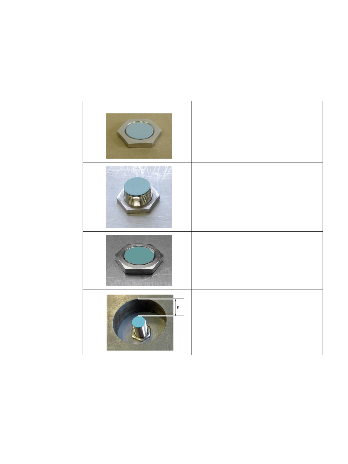
RF200 system planning
4.3.4.1
RF210R
Case
Diagram
Description
4.3 Installation guidelines
The RF210R can be flush-mounted in metal. Please allow for a possible reduction in the field
data values.
The following table shows the different arrangements for the reader with and without a
metallic environment:
a)
b)
Reader metal-free
Reader on metal,
distance from metal ≥ 12 mm
c)
d)
Reader in metal,
flush against M18 nut
Reader in metal,
all around
SIMATIC RF200
System Manual, 07/2015, J31069-D0227-U001-A9-7618
51
Page 52

RF200 system planning
Transponder
Reader without direct
metal influence
(Case a, b and d)
Reader flush-
mounted in metal
(Case c)
MDS D124
metal-free
100
82
distance all round 15 mm
MDS D127
distance all round 0 mm
MDS D160
metal-free
100
95
on metal, distance 10 mm
100
95
MDS D324
metal-free
100
90
on metal, distance 15 mm
90
90
distance all round 25 mm
MDS D421
metal-free
100
90
distance all round 0 mm
MDS D422
metal-free
100
80
distance all round 0 mm
MDS D423
metal-free
100
90
on metal, distance 0 mm
110
100 2)
distance all round 10 mm
MDS D424
metal-free
100
60
on metal, distance 15 mm
90
80
MDS D425
metal-free
100
85
on metal, distance 0 mm
100
85
MDS D428
metal-free
100
90
on metal, distance 0 mm
100
80
MDS D460
metal-free
100
90
on metal, distance 25 mm
100
90
MDS D521
metal-free
100
90
distance all round 0 mm
MDS D522
metal-free
100
80
distance all round 0 mm
4.3 Installation guidelines
To avoid any influence on the field data, in Case d, the distance a should be ≥ 10 mm.
Table 4- 16 Reduction of field data due to metal, range as %: Transponder and RF210R
1)
on metal, distance 15 mm 90 90
flush-mounted in metal;
85 80
flush-mounted in metal;
1)
1)
flush-mounted in metal;
flush-mounted in metal;
flush-mounted in metal;
flush-mounted in metal;
1)
flush-mounted in metal;
distance all round 25 mm
100 75
80 90
75 50
90 40
2)
95 85
85 75
SIMATIC RF200
52 System Manual, 07/2015, J31069-D0227-U001-A9-7618
1)
flush-mounted in metal;
75 50
flush-mounted in metal;
90 40
Page 53

RF200 system planning
Transponder
Reader without direct
metal influence
(Case a, b and d)
Reader flush-
mounted in metal
(Case c)
MDS D522
Special variant
metal-free
100
80
MDS D524
metal-free
100
60
distance all round 25 mm
MDS D528
metal-free
100
90
on metal, distance 0 mm
100
80
1)
2)
specifically for mounting in/on metallic surroundings.
4.3 Installation guidelines
flush-mounted in metal;
distance all round 0 mm
1)
on metal, distance 15 mm 90 80
flush-mounted in metal;
Mounting the transponder on or in metal is only possible with the appropriate spacer or if there is
adequate clearance to the metal.
Values of > 100 % related to non metal surroundings can occur if transponders were developed
90 40
85 75
SIMATIC RF200
System Manual, 07/2015, J31069-D0227-U001-A9-7618
53
Page 54
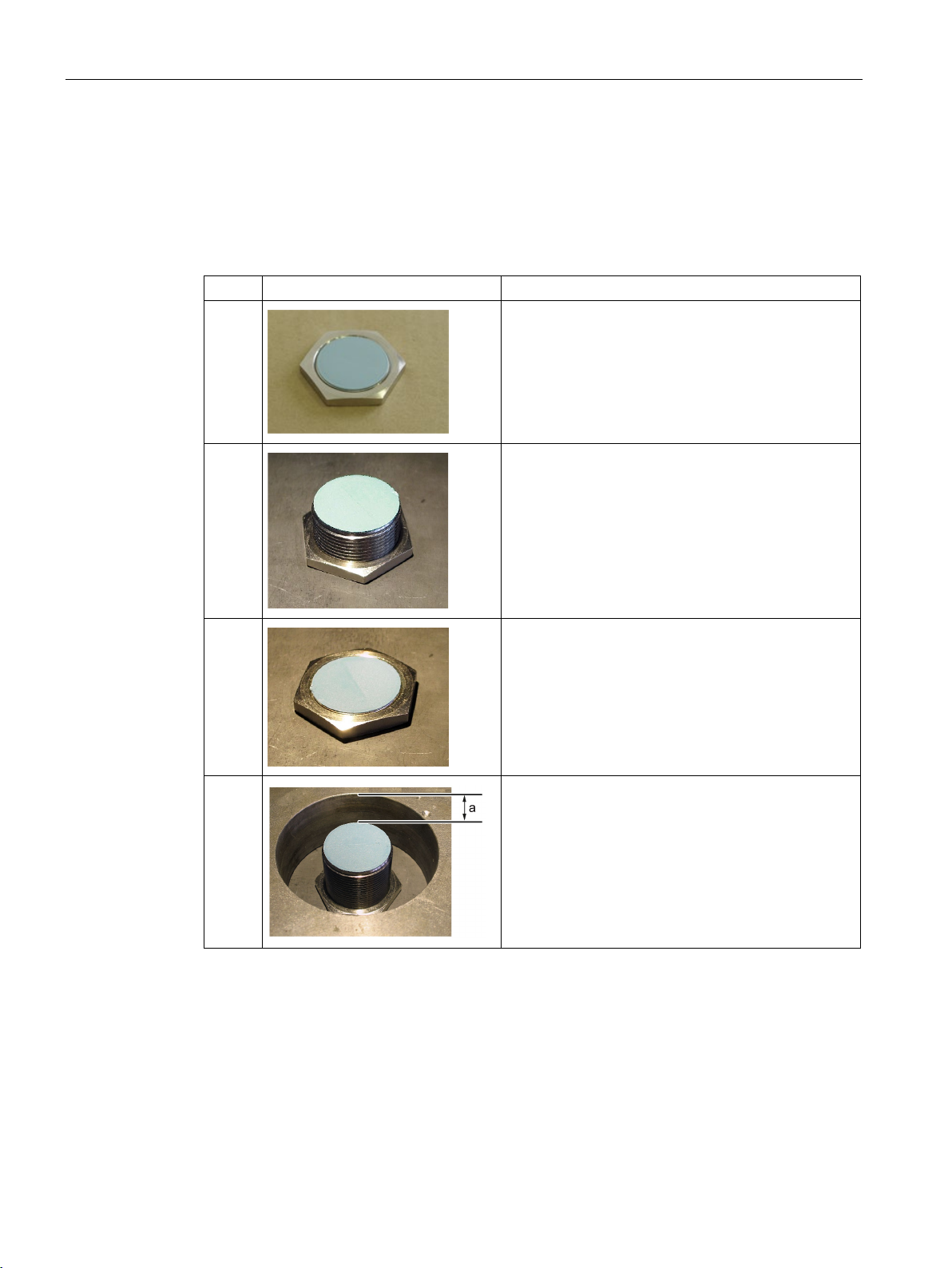
RF200 system planning
4.3.4.2
RF220R
Case
Diagram
Description
4.3 Installation guidelines
The RF220R can be flush-mounted in metal. Please allow for a possible reduction in the field
data values.
The following table shows the different arrangements for the reader with and without a
metallic environment:
a)
b)
Reader metal-free
Reader on metal,
distance from metal ≥ 12 mm
c)
d)
Reader in metal,
flush against M30 nut
Reader in metal,
all round
SIMATIC RF200
54 System Manual, 07/2015, J31069-D0227-U001-A9-7618
Page 55

RF200 system planning
Transponder
Reader without direct
metal influence
(Case a, b and d)
Reader flush-
mounted in metal
(Case c)
MDS D124
metal-free
100
94
distance all round 15 mm
MDS D126
on metal, distance 25 mm
85
70
distance all round 50 mm
MDS D160
metal-free
100
89
on metal, distance 10 mm
100
89
MDS D324
metal-free
100
90
on metal, distance 15 mm
97
86
distance all round 25 mm
MDS D422
metal-free
100
90
distance all round 0 mm
MDS D423
metal-free
100
90
on metal, distance 0 mm
125 2)
115 2)
distance all round 10 mm
MDS D424
on metal, distance 15 mm
96
89
distance all round 25 mm
MDS D425
metal-free
100
90
distance all round 25 mm
MDS D426
metal-free
100
90
on metal, distance 25 mm
90
75
distance all round 50 mm
MDS D428
metal-free
100
94
on metal, distance 0 mm
100
94
MDS D460
metal-free
100
92
on metal, distance 0 mm
100
92
4.3 Installation guidelines
To avoid any influence on the field data, in Case d, the distance a should be ≥ 15 mm.
Table 4- 17 Reduction of field data due to metal, range as %: Transponder and RF220R
1)
on metal, distance 15 mm 97 89
tag flush-mounted in metal;
1)
metal-free 100 75
86 83
flush-mounted in metal;
1)
1)
flush-mounted in metal;
80 65
93 86
flush-mounted in metal;
85 85
flush-mounted in metal;
1)
metal-free 100 93
flush-mounted in metal;
80 75
86 82
screwed onto metal 100 75
flush-mounted in metal;
95 75
SIMATIC RF200
System Manual, 07/2015, J31069-D0227-U001-A9-7618
1)
flush-mounted in metal;
80 70
1)
55
Page 56
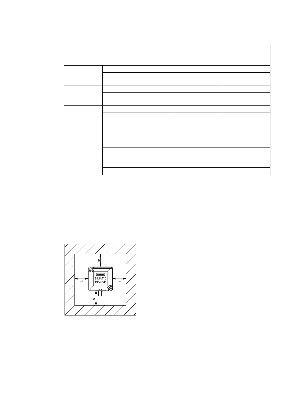
RF200 system planning
Transponder
Reader without direct
metal influence
(Case a, b and d)
Reader flush-
mounted in metal
(Case c)
MDS D522
metal-free
100
90
MDS D522
Special variant
metal-free
100
90
distance all round 0 mm
MDS D524
metal-free
100
93
on metal, distance 0 mm
96
89
distance all round 0 mm
MDS D526
metal-free
100
90
on metal, distance 25 mm
90
75
distance all round 50 mm
MDS D528
metal-free
100
94
on metal, distance 0 mm
100
94
1)
2)
specifically for mounting in/on metallic surroundings.
4.3.4.3
RF240R
4.3 Installation guidelines
flush-mounted in metal;
distance all round 0 mm
flush-mounted in metal;
1)
85 85
85 85
flush-mounted in metal;
1)
flush-mounted in metal;
86 82
80 70
Mounting the transponder on or in metal is only possible with the appropriate spacer or if there is
adequate clearance to the metal.
Values of > 100 % related to non metal surroundings can occur if transponders were developed
The RF240R can be flush-mounted in metal. Please allow for a possible reduction in the field
data values.
Figure 4-11 metal-free space RF240R
SIMATIC RF200
56 System Manual, 07/2015, J31069-D0227-U001-A9-7618
Page 57

RF200 system planning
Transponder
Reader without
direct
metal influence
Reader on
metal
(metal plate)
Reader flush-
mounted in metal
(all round
20 mm)
MDS D100
without metal
100
95
80
distance all round 20 mm
MDS D124
on metal, distance 15 mm
90
80
75
distance all round 25 mm
MDS D126
without metal
100
80
70
on metal, distance 25 mm
80
75
60
distance all round 50 mm
MDS D160
without metal
100
90
80
on metal, distance 10 mm
90
85
80
MDS D165
without metal
100
95
75
on metal, distance 25 mm
75
70
65
MDS D200
without metal
100
95
85
on metal, distance 20 mm
95
80
70
distance all round 20 mm
MDS D261
without metal
100
90
90
on metal, distance 25 mm
85
80
70
MDS D324
on metal, distance 15 mm
95
85
80
distance all round 25 mm
MDS D400
without metal
100
90
80
on metal, distance 20 mm
80
75
55
distance all round 20 mm
MDS D422
without metal
100
90
85
distance all round 0 mm
MDS D423
without metal
100
95
90
on metal, distance 0 mm
150 2)
140 2)
140 2)
distance all round 10 mm
4.3 Installation guidelines
To avoid any impact on the field data, the distance a should be ≥ 20 mm.
Table 4- 18 Reduction of field data due to metal, range as %: Transponder and RF240R
1)
on metal, distance 20 mm 95 90 75
flush-mounted in metal;
1)
without metal 100 85 75
90 75 70
flush-mounted in metal;
1)
flush-mounted in metal;
1)
85 70 65
70 55 55
1)
flush-mounted in metal,
70 60 50
1)
without metal 100 90 80
flush-mounted in metal;
1)
90 75 70
SIMATIC RF200
System Manual, 07/2015, J31069-D0227-U001-A9-7618
flush-mounted in metal,
flush-mounted in metal;
flush-mounted in metal;
75 70 50
90 60 40
70 60 60
57
Page 58

RF200 system planning
Transponder
Reader without
direct
metal influence
Reader on
metal
(metal plate)
Reader flush-
mounted in metal
(all round
20 mm)
MDS D424
without metal
100
85
80
distance all round 25 mm
MDS D425
on metal, distance 0 mm
95
85
80
MDS D426
without metal
100
80
70
on metal, distance 25 mm
90
80
70
Distance all-round 50 mm
MDS D428
without metal
100
90
85
on metal, distance 0 mm
95
85
83
MDS D460
without metal
100
90
80
on metal, distance 0 mm
90
85
80
MDS D522
metal-free
100
90
85
distance all round 0 mm
MDS D522
Special variant
metal-free
100
90
85
distance all round 0 mm
MDS D524
metal-free
100
85
80
on metal, distance 0 mm
90
80
75
distance all round 0 mm
MDS D526
metal-free
100
80
70
on metal, distance 25 mm
90
80
70
distance all round 50 mm
MDS D528
metal-free
100
90
85
on metal, distance 0 mm
95
85
83
1)
2)
specifically for mounting in/on metallic surroundings.
4.3 Installation guidelines
1)
on metal, distance 15 mm 90 80 75
flush-mounted in metal;
without metal 100 90 85
1)
80 70 65
flush-mounted in metal;
85 65 60
1)
flush-mounted in metal;
flush-mounted in metal;
1)
flush-mounted in metal;
1)
flush-mounted in metal;
90 60 40
90 60 40
80 70 65
85 65 60
Mounting the transponder on or in metal is only possible with the appropriate spacer or if there is
adequate clearance to the metal.
Values of > 100 % related to non metal surroundings can occur if transponders were developed
SIMATIC RF200
58 System Manual, 07/2015, J31069-D0227-U001-A9-7618
Page 59
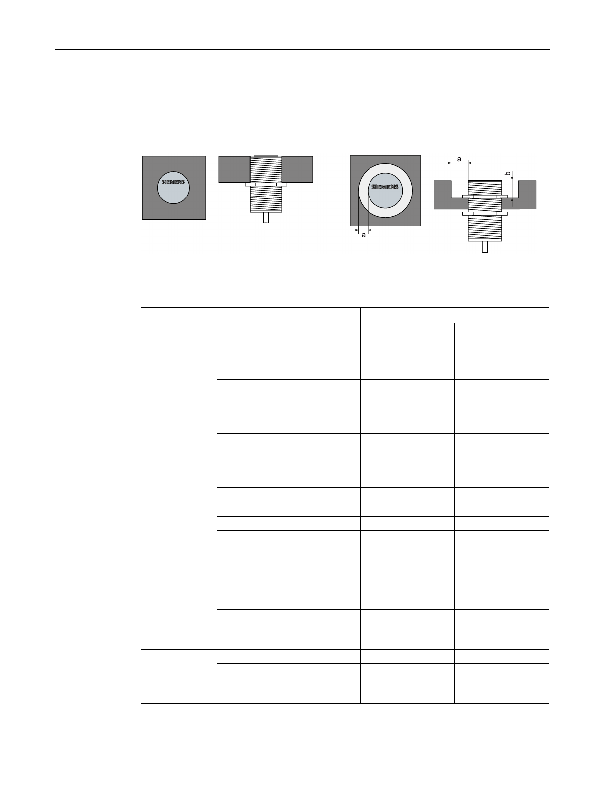
RF200 system planning
4.3.4.4
RF250R
Transponder
RF250R with ANT 3
antenna without met-
al
antenna flush-
mounted in metal
(all round 20 mm)
MDS D124
without metal
100
80
on metal, distance 15 mm
90
75
distance all round 25 mm
MDS D126
without metal
100
80
on metal, distance 25 mm
85
75
distance all round 50 mm
MDS D160
without metal
100
85
on metal, distance 10 mm
95
80
MDS D324
without metal
100
80
on metal, distance 15 mm
95
75
MDS D422
without metal
100
95
distance all round 0 mm
MDS D423
without metal
100
90
distance all round 10 mm
MDS D424
without metal
100
85
on metal, distance 15 mm
90
75
distance all round 25 mm
4.3 Installation guidelines
The RF250R reader is operated with the external antennas ANT 3, 8, 12, 18 and 30. The
antennas can be flush-mounted in metal. Please allow for a possible reduction in the field
data values.
Figure 4-12 Metal-free space for ANT 8 / ANT 12 and ANT 18 / ANT 30
Table 4- 19 Reduction of field data due to metal, range as %: Transponder and RF250R with ANT 3
1)
flush-mounted in metal;
1)
flush-mounted in metal;
1)
1)
flush-mounted in metal;
75 70
60 50
85 70
distance all round 25 mm
flush-mounted in metal;
95 80
on metal, distance 0 mm 130 2) 110 2)
flush-mounted in metal;
1)
flush-mounted in metal;
80 70
75 70
SIMATIC RF200
System Manual, 07/2015, J31069-D0227-U001-A9-7618
59
Page 60

RF200 system planning
Transponder
RF250R with ANT 3
antenna without met-
al
antenna flush-
mounted in metal
(all round 20 mm)
MDS D425
without metal
100
90
on metal, distance 0 mm
95
75
MDS D426
on metal, distance 25 mm
90
65
distance all round 25 mm
MDS D428
without metal
100
90
on metal, distance 0 mm
100
90
MDS D460
without metal
100
85
on metal, distance 10 mm
90
75
MDS D522
without metal
100
95
distance all round 0 mm
MDS D522
Special variant
without metal
100
95
distance all round 0 mm
MDS D524
without metal
100
85
on metal, distance 15 mm
90
75
distance all round 25 mm
MDS D526
without metal
100
70
on metal, distance 25 mm
90
65
distance all round 25 mm
MDS D528
on metal, distance 0 mm
100
90
1)
2)
specifically for mounting in/on metallic surroundings.
Transponder
RF250R with ANT 8
antenna without met-
al
antenna flush-
mounted in metal
MDS D117
without metal
100
85
distance all round 0 mm
4.3 Installation guidelines
1)
without metal 100 70
flush-mounted in metal;
55 45
1)
flush-mounted in metal;
flush-mounted in metal;
1)
flush-mounted in metal;
1)
flush-mounted in metal;
95 80
95 80
75 70
55 45
without metal 100 90
Mounting the transponder on or in metal is only possible with the appropriate spacer or if there is
adequate clearance to the metal.
Values of > 100 % related to non metal surroundings can occur if transponders were developed
Table 4- 20 Reduction of field data due to metal, range as %: Transponder and RF250R with ANT 8
SIMATIC RF200
60 System Manual, 07/2015, J31069-D0227-U001-A9-7618
flush-mounted in metal;
65 55
Page 61

RF200 system planning
Transponder
RF250R with ANT 8
antenna without met-
al
antenna flush-
mounted in metal
MDS D127
without metal
100
85
distance all round 0 mm
MDS D421
without metal
100
85
distance all round 0 mm
MDS D521
without metal
100
85
distance all round 0 mm
Transponder
RF250R with ANT 12
antenna without met-
al
antenna flush-
mounted in metal
(all round 7 mm)
MDS D117
without metal
100
85
distance all round 0 mm
MDS D127
without metal
100
85
distance all round 0 mm
MDS D160
without metal
100
90
on metal, distance 10 mm
90
85
MDS D421
without metal
100
90
distance all round 0 mm
MDS D422
without metal
100
90
distance all round 0 mm
MDS D425
without metal
100
90
on metal, distance 0 mm
115 2)
100
MDS D428
on metal, distance 0 mm
110
95
MDS D460
without metal
100
95
on metal, distance 10 mm
90
80
distance all round 0 mm
MDS D521
without metal
100
90
distance all round 0 mm
4.3 Installation guidelines
flush-mounted in metal;
flush-mounted in metal;
flush-mounted in metal;
Table 4- 21 Reduction of field data due to metal, range as %: Transponder and RF250R with ANT 12
70 60
75 70
75 70
flush-mounted in metal;
50 40
flush-mounted in metal;
1)
65 50
flush-mounted in metal;
65 45
flush-mounted in metal;
90 75
without metal 100 85
2)
1)
flush-mounted in metal;
85 75
SIMATIC RF200
System Manual, 07/2015, J31069-D0227-U001-A9-7618
flush-mounted in metal;
65 45
61
Page 62

RF200 system planning
Transponder
RF250R with ANT 12
antenna without met-
al
antenna flush-
mounted in metal
(all round 7 mm)
MDS D522
without metal
100
90
distance all round 0 mm
MDS D528
without metal
100
85
on metal, distance 0 mm
110
95
1)
2)
specifically for mounting in/on metallic surroundings.
Transponder
RF250R with ANT 18
antenna without met-
al
antenna flush-
mounted in metal
(all round 10 mm)
MDS D124
without metal
100
80
on metal, distance 15 mm
100
80
distance all round 25 mm
MDS D160
without metal
100
90
on metal, distance 10 mm
100
90
MDS D324
without metal
100
80
on metal, distance 15 mm
100
80
distance all round 25 mm
MDS D421
without metal
100
85
distance all round 0 mm
MDS D422
without metal
100
100
distance all round 0 mm
MDS D423
without metal
100
85
on metal, distance 0 mm
120 2)
110 2)
distance all round 10 mm
MDS D424
without metal
100
75
on metal, distance 15 mm
95
75
distance all round 25 mm
4.3 Installation guidelines
flush-mounted in metal;
Mounting the transponder on or in metal is only possible with the appropriate spacer or if there is
adequate clearance to the metal.
Values of > 100 % related to non metal surroundings can occur if transponders were developed
Table 4- 22 Reduction of field data due to metal, range as %: Transponder and RF250R with ANT 18
90 75
2)
1)
flush-mounted in metal;
1)
1)
flush-mounted in metal;
95 70
95 75
flush-mounted in metal;
65 50
flush-mounted in metal;
90 90
flush-mounted in metal;
1)
90 75
SIMATIC RF200
62 System Manual, 07/2015, J31069-D0227-U001-A9-7618
flush-mounted in metal;
95 75
Page 63

RF200 system planning
Transponder
RF250R with ANT 18
antenna without met-
al
antenna flush-
mounted in metal
(all round 10 mm)
MDS D425
without metal
100
90
on metal, distance 0 mm
100
90
MDS D428
on metal, distance 0 mm
100
85
MDS D460
without metal
100
85
on metal, distance 10 mm
100
85
MDS D521
without metal
100
85
distance all round 0 mm
MDS D522
without metal
100
100
distance all round 0 mm
MDS D522
Special variant
without metal
100
100
distance all round 0 mm
MDS D524
without metal
100
75
on metal, distance 15 mm
95
75
distance all round 25 mm
MDS D528
without metal
100
85
on metal, distance 0 mm
100
85
1)
2)
specifically for mounting in/on metallic surroundings.
Transponder
RF250R with ANT 30
antenna without met-
al
antenna flush-
mounted in metal
(all round 20 mm)
MDS D124
without metal
100
80
on metal, distance 15 mm
90
75
distance all round 25 mm
MDS D126
without metal
100
80
on metal, distance 25 mm
85
75
distance all round 50 mm
4.3 Installation guidelines
without metal 100 85
1)
flush-mounted in metal;
flush-mounted in metal;
flush-mounted in metal;
65 50
90 90
90 90
1)
flush-mounted in metal;
95 75
Mounting the transponder on or in metal is only possible with the appropriate spacer or if there is
adequate clearance to the metal.
Values of > 100 % related to non metal surroundings can occur if transponders were developed
Table 4- 23 Reduction of field data due to metal, range as %: Transponder and RF250R with ANT 30
1)
flush-mounted in metal;
75 70
SIMATIC RF200
System Manual, 07/2015, J31069-D0227-U001-A9-7618
1)
flush-mounted in metal;
60 50
63
Page 64

RF200 system planning
Transponder
RF250R with ANT 30
antenna without met-
al
antenna flush-
mounted in metal
(all round 20 mm)
MDS D160
without metal
100
85
on metal, distance 10 mm
95
80
MDS D324
on metal, distance 15 mm
95
75
distance all round 25 mm
MDS D422
without metal
100
95
distance all round 0 mm
MDS D423
without metal
100
90
on metal, distance 0 mm
130
110 2)
distance all round 10 mm
MDS D424
without metal
100
85
on metal, distance 15 mm
90
75
distance all round 25 mm
MDS D425
without metal
100
90
on metal, distance 0 mm
95
75
MDS D426
without metal
100
70
on metal, distance 25 mm
90
65
MDS D428
without metal
100
90
MDS D460
without metal
100
85
on metal, distance 10 mm
90
75
MDS D522
without metal
100
95
distance all round 0 mm
MDS D522
Special variant
without metal
100
95
distance all round 0 mm
MDS D524
without metal
100
85
on metal, distance 15 mm
90
75
distance all round 25 mm
MDS D526
without metal
100
70
on metal, distance 25 mm
90
65
distance all round 25 mm
4.3 Installation guidelines
1)
1)
without metal 100 80
flush-mounted in metal;
85 70
flush-mounted in metal;
95 80
2)
flush-mounted in metal;
1)
flush-mounted in metal;
80 70
75 70
1)
flush-mounted in metal;
55 45
distance all round 25 mm
on metal, distance 0 mm 100 90
1)
SIMATIC RF200
64 System Manual, 07/2015, J31069-D0227-U001-A9-7618
flush-mounted in metal;
flush-mounted in metal;
1)
flush-mounted in metal;
1)
flush-mounted in metal;
95 80
95 80
75 70
55 45
Page 65
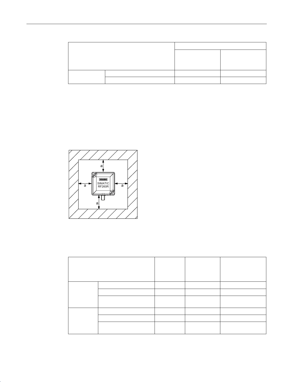
RF200 system planning
Transponder
RF250R with ANT 30
antenna without met-
al
antenna flush-
mounted in metal
(all round 20 mm)
MDS D528
without metal
100
90
on metal, distance 0 mm
100
90
1)
2)
specifically for mounting in/on metallic surroundings.
4.3.4.5
RF260R
Transponder
Reader with-
out direct
metal influ-
ence
Reader on met-
al
(metal plate)
Reader flush-
mounted in metal
(all round 20 mm)
MDS D100
without metal
100
85
65
on metal, distance 20 mm
70
65
50
MDS D124
without metal
100
93
75
on metal, distance 15 mm
95
85
70
distance all round 25 mm
4.3 Installation guidelines
Mounting the transponder on or in metal is only possible with the appropriate spacer or if there is
adequate clearance to the metal.
Values of > 100 % related to non metal surroundings can occur if transponders were developed
The RF260R can be flush-mounted in metal. Please allow for a possible reduction in the field
data values.
Figure 4-13 metal-free space for RF260R
To avoid any impact on the field data, the distance a should be ≥ 20 mm.
Table 4- 24 Reduction of field data due to metal, range as %: Transponder and RF260R
SIMATIC RF200
System Manual, 07/2015, J31069-D0227-U001-A9-7618
1)
flush-mounted in metal;
distance all round 20 mm
1)
flush-mounted in metal;
65 50 40
78 75 65
65
Page 66

RF200 system planning
Transponder
Reader with-
out direct
metal influ-
ence
Reader on met-
al
(metal plate)
Reader flush-
mounted in metal
(all round 20 mm)
MDS D126
without metal
100
85
73
distance all round 50 mm
MDS D139
on metal, distance 30 mm
95
90
75
MDS D160
without metal
100
90
75
on metal, distance 10 mm
90
80
80
MDS D165
without metal
100
85
65
on metal, distance 25 mm
65
60
45
MDS D200
without metal
100
85
70
on metal, distance 20 mm
70
65
50
distance all round 20 mm
MDS D261
without metal
100
85
70
on metal, distance 25 mm
80
70
60
MDS D324
without metal
100
90
75
on metal, distance 15 mm
90
80
70
distance all round 25 mm
MDS D339
without metal
100
90
75
on metal, distance 30 mm
95
90
75
MDS D400
without metal
100
85
70
distance all round 20 mm
MDS D423
without metal
100
95
85
on metal, distance 0 mm
120 2)
115 2)
110 2)
distance all round 10 mm
MDS D424
without metal
100
90
80
on metal, distance 15 mm
90
80
70
distance all round 25 mm
MDS D426
without metal
100
100
73
on metal, distance 25 mm
88
85
68
distance all round 50 mm
MDS D428
without metal
100
90
90
on metal, distance 0 mm
90
90
85
4.3 Installation guidelines
1)
on metal, distance 25 mm 75 68 60
flush-mounted in metal;
1)
without metal 100 90 75
1)
1)
55 53 40
flush-mounted in metal,
55 50 45
1)
flush-mounted in metal;
1)
1)
70 65 55
on metal, distance 20 mm 70 65 50
flush-mounted in metal;
55 50 45
flush-mounted in metal;
1)
flush-mounted in metal;
75 65 60
60 60 50
SIMATIC RF200
66 System Manual, 07/2015, J31069-D0227-U001-A9-7618
1)
flush-mounted in metal;
65 55 55
Page 67
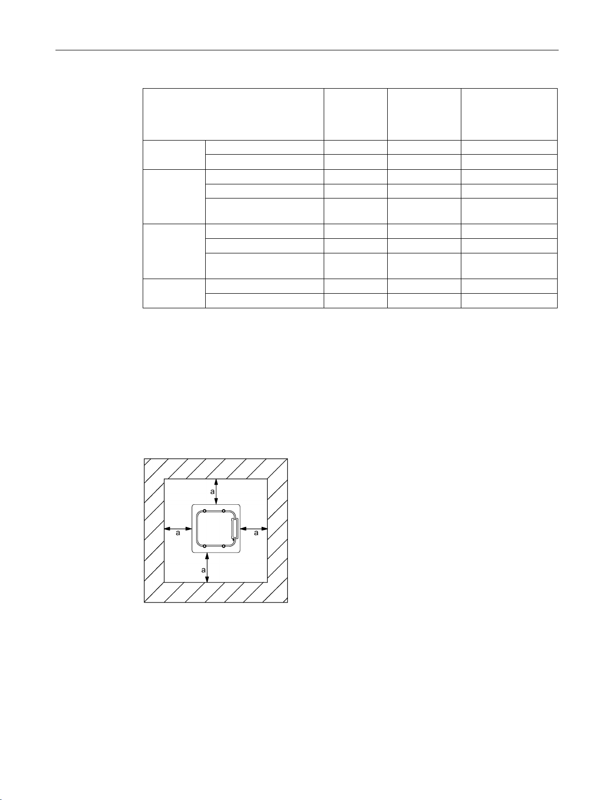
RF200 system planning
Transponder
Reader with-
out direct
metal influ-
ence
Reader on met-
al
(metal plate)
Reader flush-
mounted in metal
(all round 20 mm)
MDS D460
without metal
100
95
90
MDS D524
without metal
100
90
80
distance all round 25 mm
MDS D526
without metal
100
100
73
on metal, distance 25 mm
88
85
68
distance all round 50 mm
MDS D528
without metal
100
90
90
on metal, distance 0 mm
90
90
85
1)
2)
specifically for mounting in/on metallic surroundings.
4.3.4.6
RF290R
4.3 Installation guidelines
1)
on metal, distance 10 mm 90 85 80
1)
on metal, distance 15 mm 90 80 70
flush-mounted in metal;
1)
60 60 50
flush-mounted in metal;
65 55 55
Mounting the transponder on or in metal is only possible with the appropriate spacer or if there is
adequate clearance to the metal.
Values of > 100 % related to non metal surroundings can occur if transponders were developed
The RF290R reader is operated with the external antennas ANT D5, D6 and D10. The
antennas can be flush-mounted in metal. Please allow for a possible reduction in the field
data values.
Figure 4-14 Metal-free space for ANT D5
SIMATIC RF200
System Manual, 07/2015, J31069-D0227-U001-A9-7618
67
Page 68

RF200 system planning
Transponder
RF290R with ANT D5
Antenna on metal
(metal plate)
antenna flush-
mounted in metal
(all round 150 mm)
MDS D100
without metal
100
95
on metal, distance 20 mm
65
60
MDS D124
without metal
100
95
on metal, distance 15 mm
85
80
distance all round 25 mm
MDS D126
without metal
100
95
on metal, distance 25 mm
70
65
distance all round 50 mm
MDS D139
without metal
100
95
on metal, distance 30 mm
90
85
MDS D160
without metal
100
95
on metal, distance 10 mm
70
65
MDS D165
without metal
100
95
on metal, distance 25 mm
65
60
MDS D200
without metal
100
95
on metal, distance 20 mm
65
60
distance all round 20 mm
MDS D261
without metal
100
95
MDS D324
without metal
100
95
MDS D339
without metal
100
95
on metal, distance 30 mm
90
85
MDS D400
without metal
100
95
on metal, distance 20 mm
65
60
distance all round 20 mm
MDS D424
without metal
100
95
on metal, distance 15 mm
75
70
4.3 Installation guidelines
To avoid any influence on the field data, the distance a should be ≥ 150 or 200 mm.
Table 4- 25 Reduction of field data due to metal, range as %: Transponder and RF290R with ANT
D5
1)
flush-mounted in metal;
45 40
distance all round 20 mm
1)
flush-mounted in metal;
1)
flush-mounted in metal;
1)
1)
65 60
55 50
1)
flush-mounted in metal;
45 40
on metal, distance 25 mm 65 60
1)
on metal, distance 15 mm 75 70
1)
SIMATIC RF200
68 System Manual, 07/2015, J31069-D0227-U001-A9-7618
1)
flush-mounted in metal;
1)
45 40
Page 69

RF200 system planning
Transponder
RF290R with ANT D5
Antenna on metal
(metal plate)
antenna flush-
mounted in metal
(all round 150 mm)
MDS D426
without metal
100
95
on metal, distance 25 mm
70
65
distance all round 50 mm
MDS D460
without metal
100
95
on metal, distance 10 mm
70
65
1)
adequate clearance to the metal.
Transponder
RF290R with ANT D6
Antenna on metal
(metal plate)
antenna flush-
mounted in metal
(all round 200 mm)
MDS D100
without metal
100
95
on metal, distance 20 mm
65
60
MDS D124
without metal
100
95
on metal, distance 25 mm
80
75
MDS D126
without metal
100
95
on metal, distance 25 mm
65
60
MDS D139
without metal
100
90
on metal, distance 30 mm
80
70
MDS D160
without metal
100
90
on metal, distance 25 mm
60
55
MDS D165
without metal
100
95
on metal, distance 20 mm
50
45
MDS D200
without metal
100
95
on metal, distance 20 mm
65
60
MDS D261
on metal, distance 20 mm
50
45
MDS D324
without metal
100
95
on metal, distance 25 mm
75
70
MDS D339
without metal
100
90
on metal, distance 30 mm
80
70
MDS D400
without metal
100
95
on metal, distance 20 mm
60
55
4.3 Installation guidelines
1)
flush-mounted in metal;
1)
50 45
Mounting the transponder on or in metal is only possible with the appropriate spacer or if there is
Table 4- 26 Reduction of field data due to metal, range as %: Transponder and RF290R with ANT
D6
1)
1)
1)
1)
SIMATIC RF200
System Manual, 07/2015, J31069-D0227-U001-A9-7618
1)
1)
without metal 100 95
1)
1)
1)
69
Page 70

RF200 system planning
Transponder
RF290R with ANT D6
Antenna on metal
(metal plate)
antenna flush-
mounted in metal
(all round 200 mm)
MDS D424
without metal
100
95
on metal, distance 25 mm
75
70
MDS D426
on metal, distance 25 mm
65
60
1)
adequate clearance to the metal.
Transponder
RF290R with ANT D10
Antenna on metal
(metal plate)
antenna flush-
mounted in metal
(all round 200 mm)
MDS D100
without metal
100
95
on metal, distance 20 mm
50
40
MDS D124
without metal
100
90
on metal, distance 25 mm
70
60
MDS D126
without metal
100
95
on metal, distance 25 mm
65
60
MDS D139
without metal
100
90
on metal, distance 30 mm
80
70
MDS D160
without metal
100
90
on metal, distance 25 mm
60
55
MDS D165
without metal
100
90
on metal, distance 20 mm
40
30
MDS D200
without metal
100
95
on metal, distance 20 mm
50
40
MDS D261
without metal
100
90
on metal, distance 20 mm
40
30
MDS D324
without metal
100
90
MDS D339
without metal
100
90
on metal, distance 30 mm
80
70
MDS D400
without metal
100
95
on metal, distance 20 mm
50
40
MDS D424
without metal
100
90
on metal, distance 25 mm
70
60
4.3 Installation guidelines
1)
1)
without metal 100 95
Mounting the transponder on or in metal is only possible with the appropriate spacer or if there is
Table 4- 27 Reduction of field data due to metal, range as %: Transponder and RF290R with ANT
D10
1)
1)
1)
1)
1)
1)
1)
on metal, distance 25 mm 70 60
1)
1)
SIMATIC RF200
70 System Manual, 07/2015, J31069-D0227-U001-A9-7618
1)
Page 71

RF200 system planning
Transponder
RF290R with ANT D10
Antenna on metal
(metal plate)
antenna flush-
mounted in metal
(all round 200 mm)
MDS D426
without metal
100
95
on metal, distance 25 mm
70
65
MDS D524
on metal, distance 25 mm
70
60
MDS D526
without metal
100
95
on metal, distance 25 mm
70
65
1)
adequate clearance to the metal.
4.3.5
Installation and connection of 2 to 6 antennas with one RF290R reader
4.3 Installation guidelines
1)
1)
without metal 100 90
1)
Mounting the transponder on or in metal is only possible with the appropriate spacer or if there is
If several antennas need to be operated on one reader, this can be achieved by using the
antenna splitter or the antenna multiplexer RF260X.
Note that the antenna splitter is a purely passive device that splits the power at the input to
two outputs and therefore halves it. This is possible both in PC mode (RS-232) and CM
mode (RS-422). You can cascade the antenna splitters in such a way that up to 4 antennas
can be connected at the same time.
The antenna multiplexer RF260X works only in PC mode (RS-232) in time division multiplex
mode. This means that each antenna operates with full power for a certain time before the
device moves on automatically to the next antenna. The antenna multiplexer normally
operates in scan mode or buffered read mode which with suitable parameter assignment add
the information about the antenna number to the reply of the transponder. You can operate
up to six antennas on one reader via the multiplexer.
SIMATIC RF200
System Manual, 07/2015, J31069-D0227-U001-A9-7618
71
Page 72
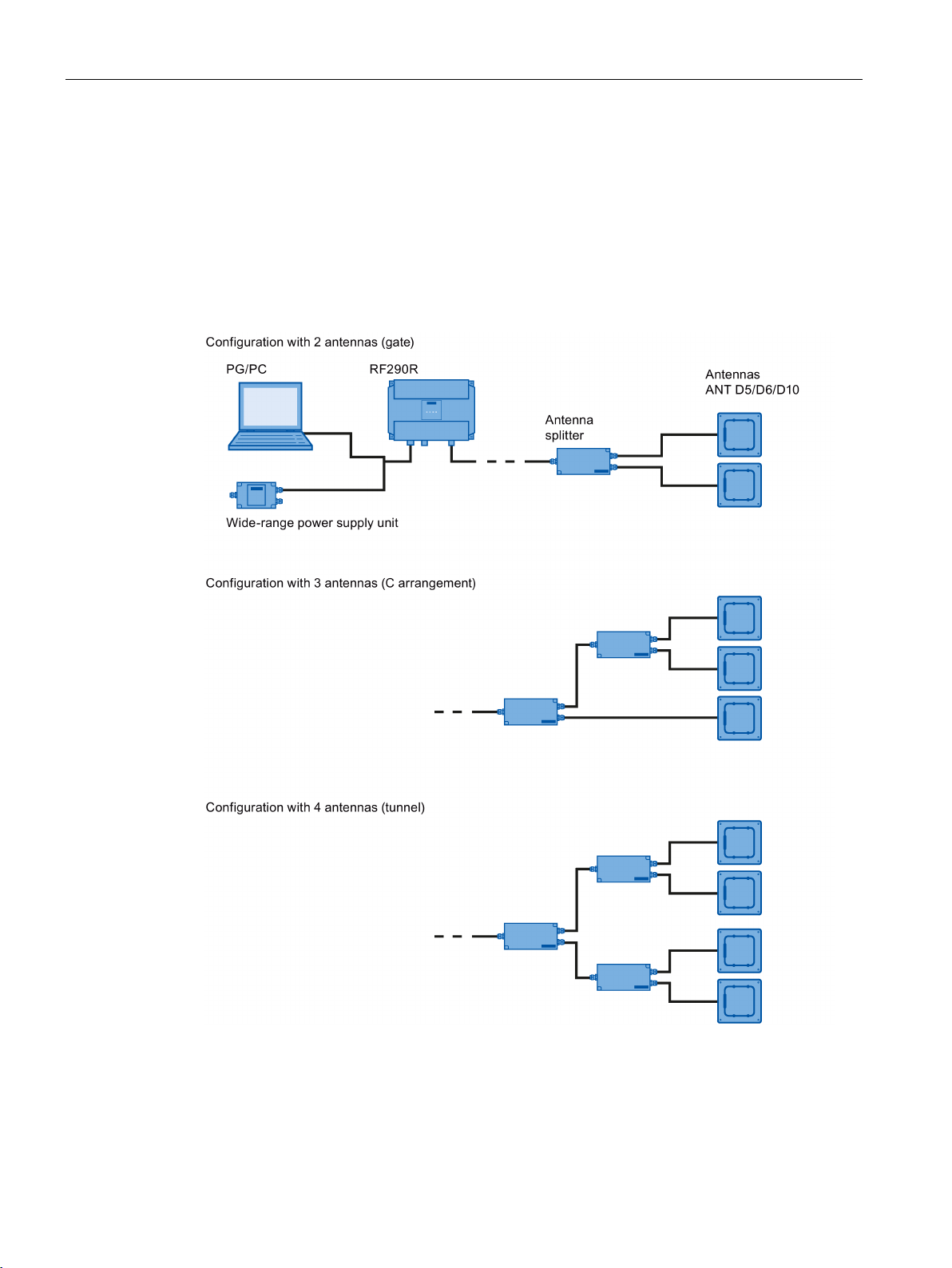
RF200 system planning
4.3.5.1
Installation options with the antenna splitter (2-4 antennas)
Possible configurations of the antennas
4.3 Installation guidelines
The antenna installations described here have been designed for reading smartlabels
(transponders) on goods on conveyor belts, conveyor systems or pallets.
A prerequisite is that there are no magnetically conducting materials (e.g. metal) in the
vicinity of the antenna or the label.
Figure 4-15 Possible configuration of RF290R with ANT D5/D6/D10
SIMATIC RF200
72 System Manual, 07/2015, J31069-D0227-U001-A9-7618
Page 73
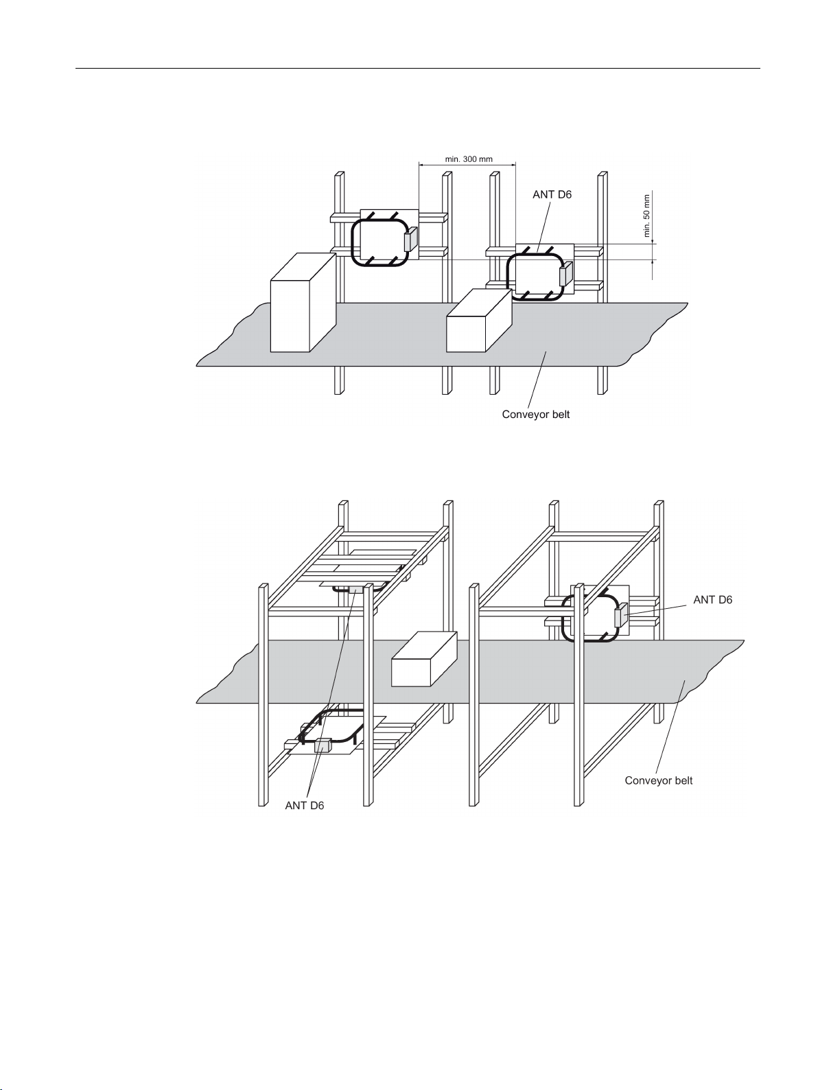
RF200 system planning
Installation examples
4.3 Installation guidelines
Figure 4-16 Installation example with 2 ANT D6 (portal)
Figure 4-17 Installation example with ANT D6 (C arrangement)
SIMATIC RF200
System Manual, 07/2015, J31069-D0227-U001-A9-7618
73
Page 74
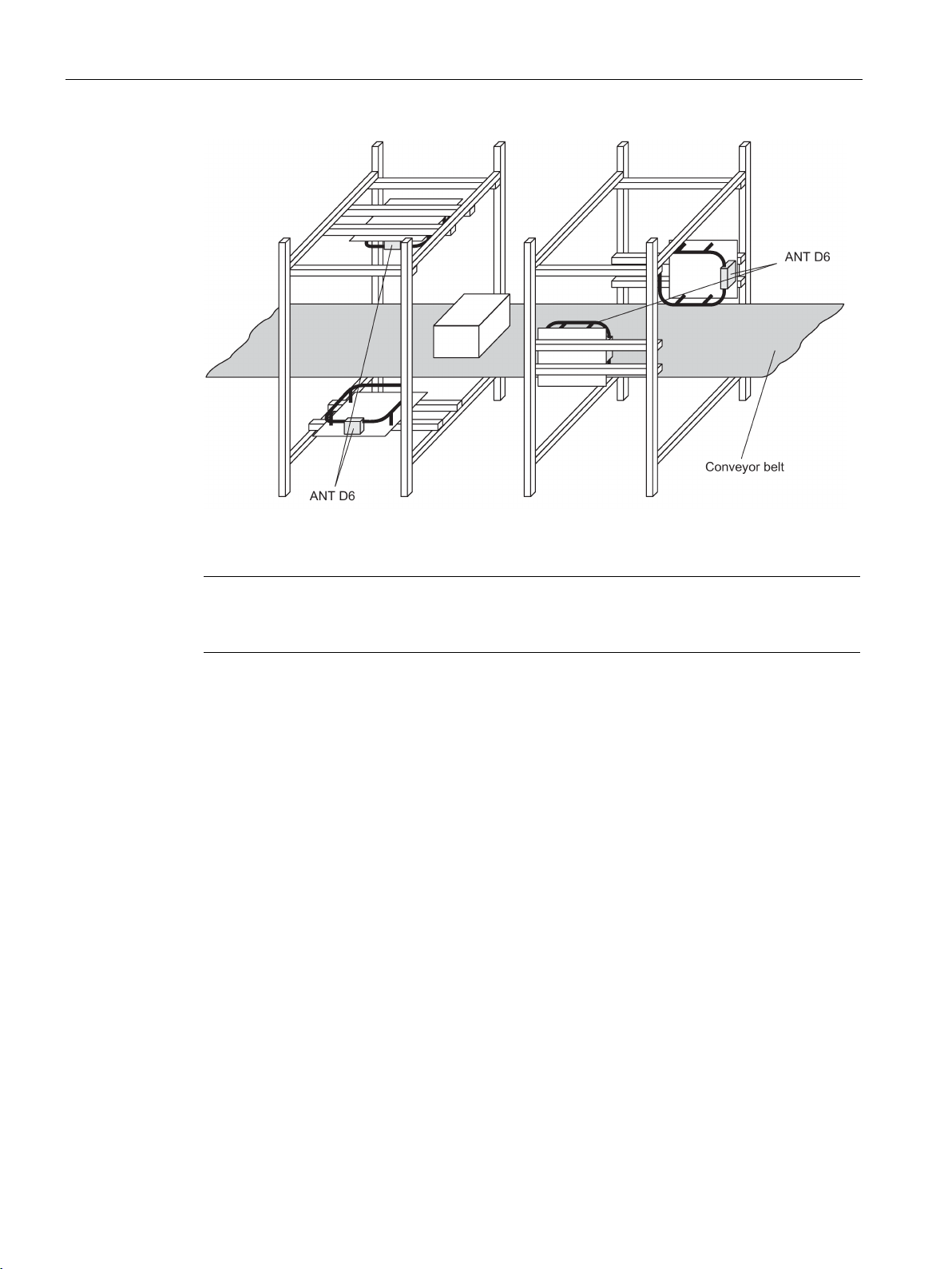
RF200 system planning
Note
The minimum spacings between the antennas for
less than the distances described because this configuration has the same phase.
4.3 Installation guidelines
Figure 4-18 Installation example with ANT D6 (tunnel)
operation with only one reader may be
SIMATIC RF200
74 System Manual, 07/2015, J31069-D0227-U001-A9-7618
Page 75

RF200 system planning
4.3.5.2
Antenna installation
Configuring instructions
Note
Remember that the entire acquisition range of the antenna is larger than the transmission
window in which the transponder is normally configured. This means there can be label
alignments where even labels outside the transmission window will be
aligned in parallel with the antennas, for example, can also be detected at larger distances
beside or outside the antenna range.
For this reason, goods with labels must not be stored within a distance of up to 0.5 m from
the installati
To achieve three
requirements must be met:
•
•
•
•
•
•
•
Note
The RF290R reader is not capable of multitag operation in the CM mode.
4.3 Installation guidelines
The antenna installation described below enables detection of transponders moving
horizontally through the installation. Depending on the installation (antennas exactly opposite
each other or offset in parallel), the label is aligned in parallel with the antennas or arbitrarily.
The size of the sensing range depends on the label alignment:
on. If this cannot be complied with, the antennas must be shielded.
-dimensional detection of the labels in the sensing range, the following
The gate width must be less than or equal to 800 mm.
The antenna size of the labels should be at least the size of an ISO card (85 mm x 54
mm).
The distance from label to label must be greater than 100 mm. The distance from label to
label can be reduced if the gate width is correspondingly reduced. This applies especially
for distances under 50 mm.
There should be no more than 16 labels within the sensing range of the antennas at the
same time.
The number of labels can be increased if the gate width is correspondingly reduced and
the maximum speed suitably adapted.
The maximum speed of the labels must not exceed 1 m/s. (This depends on the number
and alignment of the labels, the number of data blocks to be processed, the data protocol
required and the label type).
To the front and sides of the antenna, there must be a distance of more than 150 mm to
metal parts.
There must be no interference to the write/read device from other electrical equipment in
the surrounding area.
identified. Labels
SIMATIC RF200
System Manual, 07/2015, J31069-D0227-U001-A9-7618
75
Page 76

RF200 system planning
Required components
Number for installation
with
Component
Article number
2 ant.
3 ant.
4 ant.
RF182C: 6GT2002-0JD10
ANT D10: 6GT2698-5AF00
cover
6GT2698-5AD00
1 2 3
Antenna splitter
6GT2603-0AC00
(for PC mode only)
US: 6GT2898-0AA20
(for PC mode only)
6GT2891-4EH ...
Installation information
4.3 Installation guidelines
For installation with
● 2 antennas (gate)
● 3 antennas (C arrangement)
● 4 antennas (tunnel)
the following components are required:
Table 4- 28 Components required for setting up with 2, 3 or 4 antennas
1 1 1 Basic device:
RF290R (↔ CM or PC)
2 3 4 Antenna ANT D5 / D6 / D10 optionally:
2 3 4 With ANT D6 if required:
1 1 1 Wide-range power supply unit for
SIMATIC RF systems
1 1 1 24 V connecting cable, length 5 m
1 1 1 Connecting cable:
RF290R ↔ PC
or
RF290R ↔ CM
RF290R: 6GT2821-0AC12
optionally:
ASM 475: 6GT2002-0GA10
ASM 456: 6GT2002-0ED00
RF170C: 6GT2002-0HD00
RF180C: 6GT2002-0JD00
ANT D5: 6GT2698-5AA10
ANT D6: 6GT2698-5AB00
EU: 6GT2898-0AA00
UK: 6GT2898-0AA10
6GT2491-1HH50
6GT2891-4KH ...
optionally:
6GT2891-4F ...
SIMATIC RF200
76 System Manual, 07/2015, J31069-D0227-U001-A9-7618
The cables on the antennas and the antenna splitter are 3.3 m or 10.5 m long. The
write/read device must be installed in the vicinity of the antennas. If there are greater
distances between the write/read device and the antennas, the antenna cable can be
increased by 7.2 m with the extension (6GT2691-0DH72). This results in shorter ranges.
Page 77
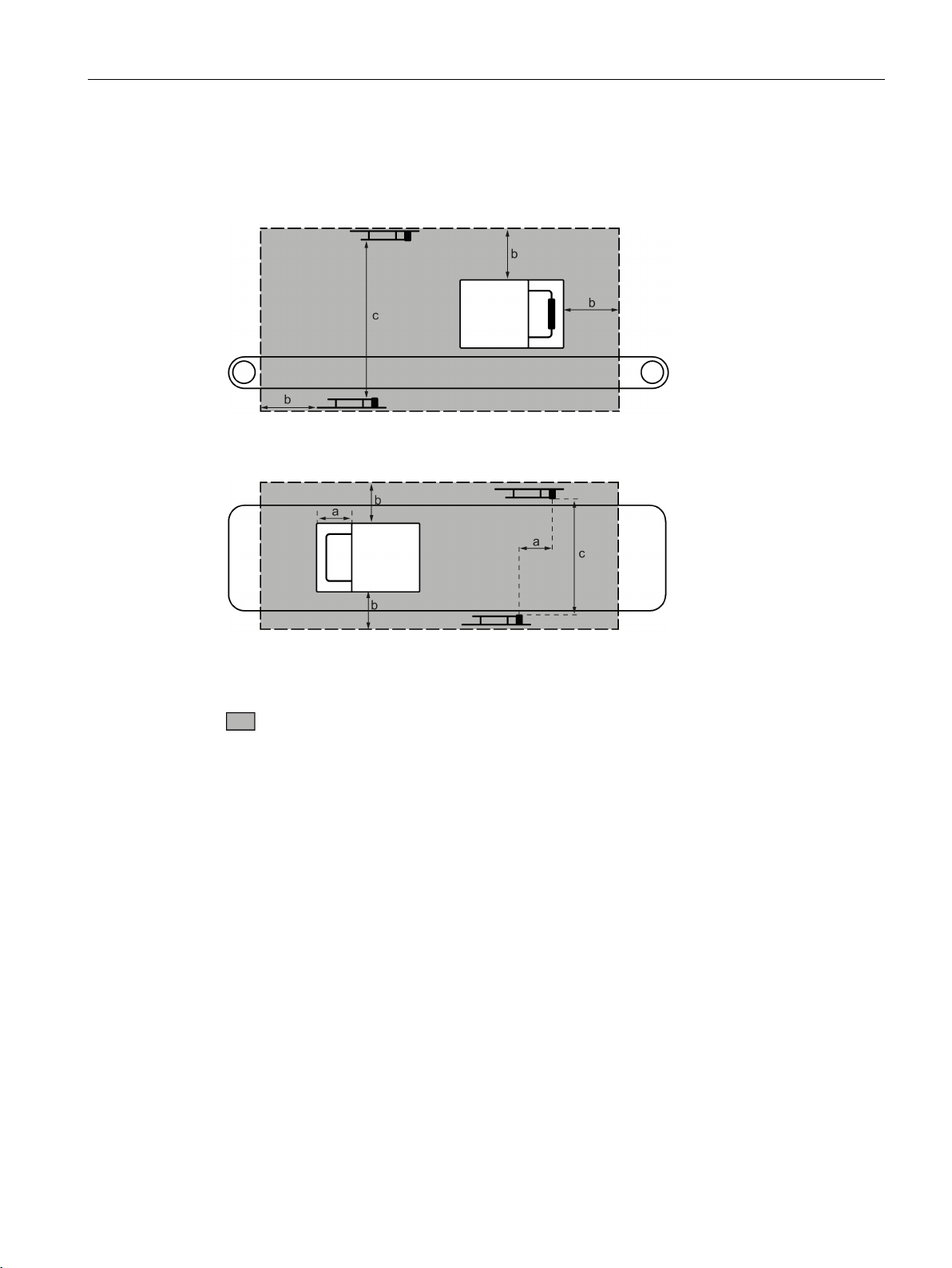
RF200 system planning
Metal-free space
a
approx. half antenna length
b
min. 100 mm
c
max. 600 mm
Metal in the vicinity of the antennas
4.3 Installation guidelines
To guarantee perfect functioning of the individual installation versions, all larger metal parts
in the vicinity of the antennas must be removed.
Figure 4-19 Metal-free space, side view (based on the example of a tunnel arrangement on a
conveyor belt)
Metal-free space
Figure 4-20 Metal-free space, view from above (based on the example of a tunnel arrangement on a
conveyor belt)
If metal in the vicinity of the antennas cannot be avoided, the following must be noted:
● There must be a minimum allround gap of 100 mm between the antenna and metal.
Serious loss of sensing range must be expected above 50 mm. There is no discernible
influence at distances greater than 150 mm from the metal.
● The influence of the metal depends heavily on its size and shape. Thin metal rods have
less influence on the magnetic field than large surfaces.
● Larger metal surfaces (edge length > 50 mm) in parallel with the antennas or labels result
in a short-circuit of the magnetic lines of force. As a result, the labels cannot be read.
● Metal parts under the conveyor belt change the direction of the magnetic lines of force.
Serious loss of sensing range must be expected as a result. Horizontally aligned labels
cannot be read in such cases.
SIMATIC RF200
System Manual, 07/2015, J31069-D0227-U001-A9-7618
77
Page 78

RF200 system planning
The metal parts must not form closed loops or circuits. If necessary, these must be
electrically interrupted at one point
Notes on installing and laying the antenna cable
4.3 Installation guidelines
●
● The metal parts in the immediate vicinity of the antenna must be grounded in a mesh with
a good HF connection.
● Since the write/read device is installed in a metal housing, and the antennas can couple
into the cables to the write/read device, it must be installed at a distance of at least 500
mm from the antennas.
.
To suppress possible interference, an EMC hinged ferrite choke must be fitted to the
antenna cables (as well as the antenna cable between the reader and the antenna splitter).
The coaxial cable must be wound tightly at least four times through the EMC ring core. The
maximum distance between the connecting plug for the reader or the antenna splitter and
the ring core must be 100 mm.
The antenna cable must always be run vertically from the antennas. A minimum distance of
200 mm to the antennas must be observed as the cables continue. Otherwise, performance
losses must be expected.
There must be a distance of at least 300 mm between antenna cables and parallel power
cables.
Unrequired cable length must be secured in a bundle with a diameter of 100 to 150 mm.
If the standard antenna cable is too short, it can be increased by 7.20 m with the extension.
Slight range losses must be expected here.
To achieve optimal read ranges, the antenna cable should not be shortened or lengthened.
SIMATIC RF200
78 System Manual, 07/2015, J31069-D0227-U001-A9-7618
Page 79
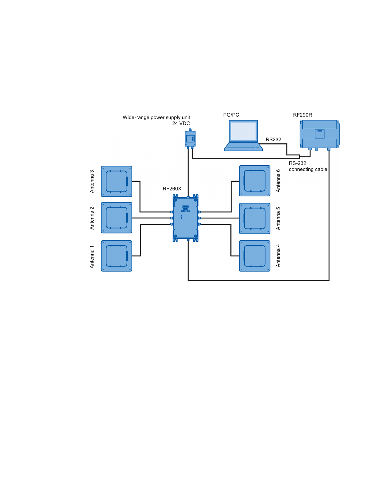
RF200 system planning
4.3.5.3
Installation options with the antenna multiplexer (2-6 antennas)
4.3 Installation guidelines
You can operate up to six antennas on one reader via the multiplexer.
The data is processed sequentially.
Antenna switchover is performed in time-multiplex mode, so by connecting several antennas
together, the processing time / activation time per antenna is lengthened accordingly.
Figure 4-21 Configuration example of the antenna multiplexer with ANT D5
SIMATIC RF200
System Manual, 07/2015, J31069-D0227-U001-A9-7618
79
Page 80

RF200 system planning
4.3.6
Chemical resistance of the transponders
4.3.6.1
Overview of the transponders and their housing materials
Housing material
Transponder
MDS D423
MDS D400
MDS D524
PA6
MDS D127
MDS D528
4.3 Installation guidelines
The following sections describe the resistance to chemicals of the various transponders.
Resistance to chemicals depends on the housing material used to manufacture the
transponders.
The following table provides an overview of the housing materials of the transponders:
Table 4- 29 Overview of the housing materials of the transponders
Polyphenylene sulfide (PPS) MDS D117
MDS D124 (6GT2600-0AC10)
MDS D139
MDS D160
MDS D339
Polycarbonate (PC) MDS D100 (6GT2600-0AD10)
Polyvinyl chloride (PVC) MDS D100 (6GT2600-0AD00-0AX0)
MDS D200
Epoxy resin MDS D124 (6GT2600-0AC00)
MDS D324
MDS D421
MDS D424
MDS D460
MDS D521
SIMATIC RF200
80 System Manual, 07/2015, J31069-D0227-U001-A9-7618
PA6.6 GF30 MDS D126
MDS D422
MDS D425
MDS D426
MDS D428
MDS D522
MDS D526
Page 81

RF200 system planning
Note
Chemical substances not listed
The following sections describe the resistance of the various
substances. If you require information about chemical substances that are not listed, contact
Customer Support.
4.3.6.2
Polyphenylene sulfide (PPS)
Substance
Test conditions
Rating
Concentration [%]
Temperature [°C]
Acetone 55 ℃
عربي
n-Butanol (butyl alcohol)
80 ℃
عربي
Butanone-2 (methyl ethyl ketone)
60 ℃
عربي
n-Butyl acetate
80 ℃
عربي
Brake fluid 80 ℃
عربي
Calcium chloride (saturated)
80 ℃
عربي
Diesel fuel 80 ℃
عربي
Diethyl ether
23 ℃
عربي
Frigen 113 23 ℃
عربي
Anti-freeze
120 ℃
عربي
Kerosene 60 ℃
عربي
Methanol 60 ℃
عربي
Engine oil 80 ℃
عربي
Sodium chloride (saturated)
80 ℃
○○○○
5%
80 ℃
○○
Sodium hydroxide solution
30%
90 ℃
○○○○
Nitric acid
10%
23 ℃
○○○○
Hydrochloric acid
10%
80 ℃
-
10%
23 ℃
○○○○
10%
80 ℃
○○
30%
23 ℃
○○○○
Tested fuels
80 ℃
○○○○
4.3 Installation guidelines
transponders to specific
The data memory has special chemical resistance to solutions up to a temperature of 200
°C. A reduction in the mechanical properties has been observed in aqueous solutions of
hydrochloric acid (HCl) and nitric acid (HNO3) at 80 °C. The plastic housings are resistant to
all types of fuel including methanol.
Table 4- 30 Chemical resistance - polyphenylene sulfide (PPS)
Sodium hydroxide 30% 80 ℃ ○○○○
Sodium hypochlorite
(30 or 180 days)
Sulfuric acid
5% 80 ℃ -
SIMATIC RF200
System Manual, 07/2015, J31069-D0227-U001-A9-7618
81
Page 82

RF200 system planning
Substance
Test conditions
Rating
Concentration [%]
Temperature [°C]
Toluene
Xylene
80 ℃
○○
75 ℃
○○○○
Explanation of the rating
○○○○
Resistant
○○○
Practically resistant
○○
Conditionally resistant
○
Less resistant
-
Not resistant
4.3.6.3
Polycarbonate (PC)
Substance
Test conditions
Rating
Concentration [%]
Temperature [°C]
Mineral lubricants
○○
Aliphatic hydrocarbons
○○○○
Aromatic hydrocarbons
-
Gasoline
-
Weak mineral acids
○○○○
Strong mineral acids
○○
Weak organic acids
○○○○
Strong organic acids
○○
Oxidizing acids
-
Weak alkaline solutions
-
Strong alkaline solutions
-
Perchloroethylene
-
Alcohols
○○
Hot water (hydrolysis resistance)
-
4.3 Installation guidelines
FAM testing fluid
acc. to DIN 51 604-A
1, 1, 1-Trichloroethane
Zinc chloride (saturated)
Table 4- 31 Chemical resistance - polycarbonate (PPS)
80 ℃ ○○
80 ℃ ○○○○
SIMATIC RF200
82 System Manual, 07/2015, J31069-D0227-U001-A9-7618
Trichloroethylene -
Acetone -
Page 83

RF200 system planning
Explanation of the rating
○○○○
Resistant
○○
Conditionally resistant
○
Less resistant
-
Not resistant
4.3.6.4
Polyvinyl chloride (PVC)
Substance
Test conditions
Rating
Concentration [%]
Temperature [°C]
Salt water
5 %
○○○○
Sugared water
10 %
○○○○
Acetic acid, w.
5 %
○○○○
Sodium carbonate, w.
5 %
○○○○
Ethyl alcohol, w.
60 %
○○○○
Ethylene glycol
50 %
○○○○
(acc. to ISO 1817)
Human sweat
○○○○
Explanation of the rating
○○○○
Resistant
○○○
Practically resistant
○○
Conditionally resistant
○
Less resistant
-
Not resistant
w.
Water solution
4.3.6.5
Epoxy resin
Substance
Test conditions
Rating
Concentration [%]
Temperature [°C]
Allyl chloride
20 ℃
○○○○
50 %
20 ℃
○○○○
100 %
20 ℃
○○
4.3 Installation guidelines
○○○ Practically resistant
Table 4- 32 Chemical resistance - polyvinyl chloride (PVC)
Fuel B
○○○○
SIMATIC RF200
System Manual, 07/2015, J31069-D0227-U001-A9-7618
Table 4- 33 Chemical Resistance - epoxy resin
Formic acid
Ammonia, gaseous 20 ℃ ○○○○
83
Page 84

RF200 system planning
Substance
Test conditions
Rating
Concentration [%]
Temperature [°C]
Ammonia, liquid, water-free
20 ℃
-
Ammonium hydroxide
10 %
20 ℃
○○○○
60 ℃
○○○○
Ethyl acrylate
20 ℃
○○○○
Ethyl glycol
60 ℃
○○○○
Gasoline, aroma-free
20 ℃
○○○○
Gasoline, containing benzene
20 ℃
○○○○
Benzoates (Na–, Ca– among others)
40 ℃
○○○○
Benzoic acid
20 ℃
○○○○
Benzene 20 ℃
○○○○
Borax 60 ℃
○○○○
Boric acid 20 ℃
○○○○
Bromine, liquid
20 ℃
-
Bromides (K–, Na– among others)
60 ℃
○○○○
Bromoform
100 %
20 ℃
○○○○
Bromine water
20 ℃
-
Butadiene (1,3–)
20 ℃
○○○○
Butane, gaseous
20 ℃
○○○○
Butanol 20 ℃
-
Butyric acid
100 %
20 ℃
○○
others)
Chlorine, liquid
20 ℃
-
Chlorine, gaseous, dry
100 %
20 ℃
-
Chlorobenzene
20 ℃
○○○○
others)
Chloroform
20 ℃
-
Chlorophyll
20 ℃
○○○○
Chlorosulfuric acid
100 %
20 ℃
-
Chlorine water (saturated solution)
20 ℃
○○
Chromates (K–, Na– among others)
Up to 50 %
40 ℃
○○○○
Chromic acid
Up to 30 %
20 ℃
-
Chromosulfuric acid
20 ℃
-
Citric acid 20 ℃
○○○○
Cyanamide
20 ℃
○○○○
Cyanides (K–, Na– among others)
60 ℃
○○○○
Dextrin, w. 60 ℃
○○○○
Diethyl ether
20 ℃
○○○○
Diethylene glycol
60 ℃
○○○○
4.3 Installation guidelines
Ethanol 40 ℃ ○○○○
Carbonates (ammonium–, Na– among
Chlorides (ammonium–, Na– among
60 ℃ ○○○○
60 ℃ ○○○○
SIMATIC RF200
84 System Manual, 07/2015, J31069-D0227-U001-A9-7618
Page 85

RF200 system planning
Substance
Test conditions
Rating
Concentration [%]
Temperature [°C]
Dimethyl ether
20 ℃
○○○○
Dioxane 20 ℃
-
Acetic acid
100 %
20 ℃
○○
Ethanol 60 ℃
○○○○
Fixing bath
40 ℃
○○○○
among others)
Hydrofluoric acid
Up to 40 %
20 ℃
○○○○
Formaldehyde
50 %
20 ℃
○○○○
Formamide
100 %
20 ℃
○○○○
Gluconic acid
20 ℃
○○○○
Glycerine 60 ℃
○○○○
Glycol 60 ℃
○○○○
Urine 20 ℃
○○○○
Uric acid 20 ℃
○○○○
Hydroxides (ammonium...)
10 %
20 ℃
○○○○
Hydroxides (Na–, K–)
40 %
20 ℃
○○○○
Hydroxides (alkaline earth metal)
60 ℃
○○○○
Hypochlorites (K–, Na– among others)
60 ℃
○○○○
Silicic acid 60 ℃
○○○○
Cresol
Up to 90 %
20 ℃
-
Methanol
100 %
40 ℃
○○○○
Methylene chloride
20 ℃
-
Lactic acid
100 %
20 ℃
○○
Mineral oils
40 ℃
○○○○
others)
Nitroglycerin
20 ℃
-
Oxalic acid
20 ℃
○○○○
Phenol
1 %
20 ℃
○○○○
others)
50 %
60 ℃
○○○○
85 %
20 ℃
○○○○
Propanol 20 ℃
○○○○
Nitric acid
25 %
20 ℃
-
Hydrochloric acid
10 %
20 ℃
-
Brine 60 ℃
-
Sulfur dioxide
100 %
20 ℃
○○
4.3 Installation guidelines
Developer 40 ℃ ○○○○
Fluorides (ammonium–, K–, Na–
Iodides (K–, Na– among others) 60 ℃ ○○○○
40 ℃ ○○○○
Nitrates (ammonium..., K– among
Phosphates (ammonium..., Na– among
Phosphoric acid
Carbon disulfide 100 % 20 ℃ -
SIMATIC RF200
System Manual, 07/2015, J31069-D0227-U001-A9-7618
60 ℃ ○○○○
60 ℃ ○○○○
85
Page 86

RF200 system planning
Substance
Test conditions
Rating
Concentration [%]
Temperature [°C]
Sulfuric acid
40 %
20 ℃
-
Sulfurous acid
20 ℃
○○
others)
others)
Tar, aroma-free
60 ℃
○○○○
Turpentine 20 ℃
○○○○
Trichloroethylene
20 ℃
-
Hydrogen peroxide
30 %
20 ℃
○○○○
Tartaric acid
20 ℃
○○○○
Explanation of the rating
○○○○
Resistant
○○○
Practically resistant
○○
Conditionally resistant
○
Less resistant
-
Not resistant
4.3.6.6
PA6.6 GF30
Substance
Test conditions
Rating
Concentration [%]
Temperature [°C]
Mineral lubricants
○○○○
Aliphatic hydrocarbons
○○○○
Aromatic hydrocarbons
○○○○
Weak mineral acids
○○○
Strong mineral acids
-
Weak organic acids
○○
Strong organic acids
-
Oxidizing acids
-
Strong alkaline solutions
-
Trichloroethylene
○○○○
Perchloroethylene
○○○○
Acetone
○○○○
4.3 Installation guidelines
Soap solution 60 ℃ ○○○○
Sulphates (ammonium..., Na– among
60 ℃ ○○○○
Sulfites (ammonium..., Na– among
Table 4- 34 Chemical resistance - PA6.6 GF30
60 ℃ -
SIMATIC RF200
86 System Manual, 07/2015, J31069-D0227-U001-A9-7618
Gasoline ○○○○
Weak alkaline solutions ○○
Page 87

RF200 system planning
Substance
Test conditions
Rating
Concentration [%]
Temperature [°C]
Alcohols
○○○○
Hot water (hydrolysis resistance)
○○
Explanation of the rating
○○○○
Resistant
○○○
Practically resistant
○○
Conditionally resistant
○
Less resistant
4.4
Further information
4.4 Further information
- Not resistant
Further information on "Fundamentals of application planning" and "EMC" can be found in
RF300 system manual (https://support.industry.siemens.com/cs/ww/en/view/21738946
).
SIMATIC RF200
System Manual, 07/2015, J31069-D0227-U001-A9-7618
87
Page 88

RF200 system planning
4.4 Further information
SIMATIC RF200
88 System Manual, 07/2015, J31069-D0227-U001-A9-7618
Page 89

5
NOTICE
Pulling and plugging readers
Note
IO-Link variants of the RF200 readers
The IO
these in the "SIMATIC RF200 IO
(
Pull or plug the reader only when the power supply is turned off
If this is not observed, under certain conditions, the reader will not start up correctly and
communication with a transponder will not be possible.
-Link variants of the readers are not included in the system manual. You will find
-Link
https://support.industry.siemens.com/cs/ww/en/view/60641859)" operating instructions.
SIMATIC RF200
System Manual, 07/2015, J31069-D0227-U001-A9-7618
89
Page 90
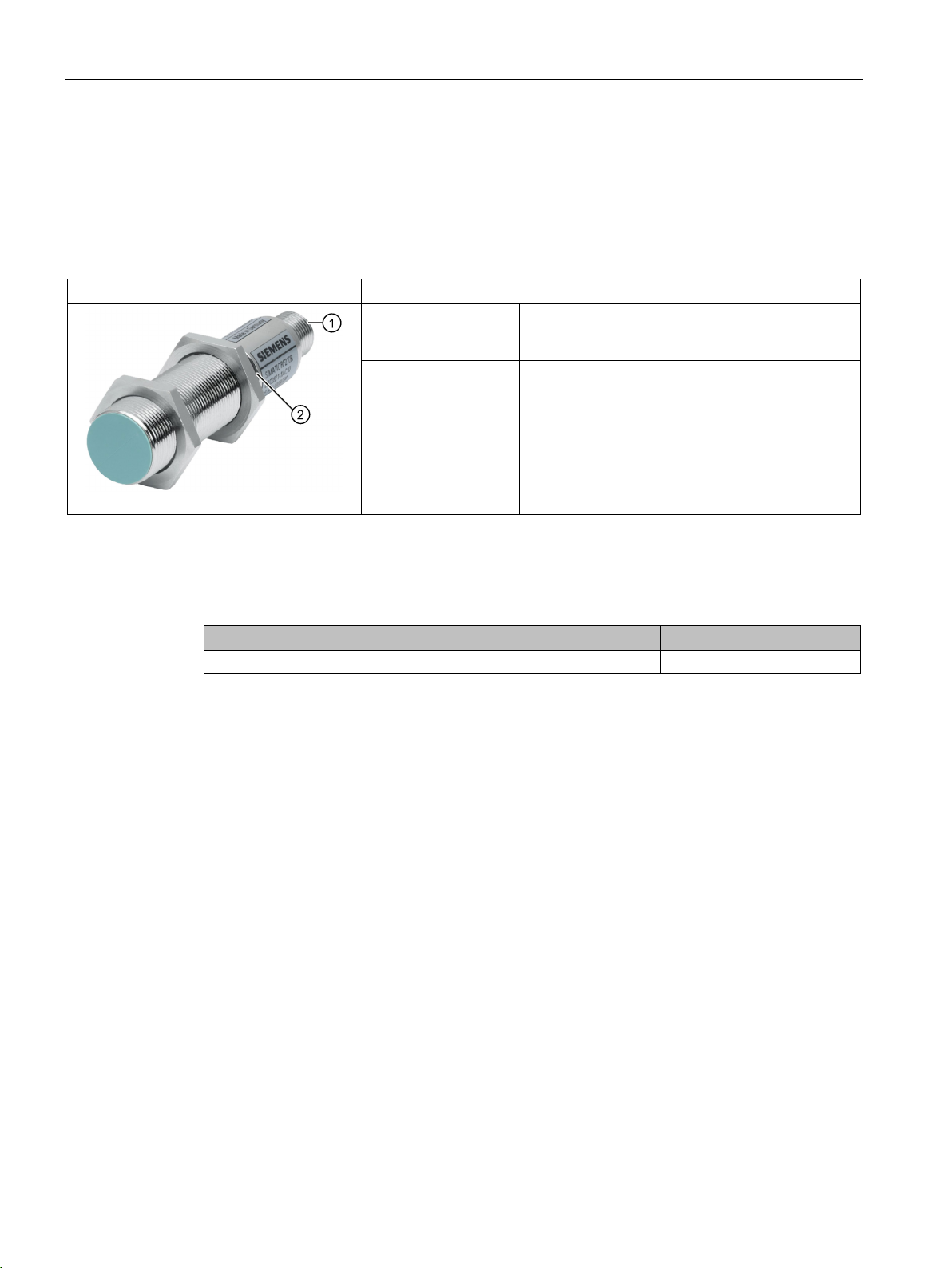
Readers
5.1
SIMATIC RF210R
5.1.1
Features
SIMATIC RF210R
Characteristics
②
5.1.2
RF210R ordering data
Article number
RF210R with RS422 interface (3964R)
6GT2821-1AC10
5.1 SIMATIC RF210R
Design
Application Identification tasks on assembly lines in harsh in-
① RS422 interface
Status display
dustrial environments
SIMATIC RF200
90 System Manual, 07/2015, J31069-D0227-U001-A9-7618
Page 91

Readers
5.1.3
Pin assignment RF210R with RS422 interface
Pin
Pin
Device end
8-pin M12
Assignment
1
+ 24 V
3
0 V
4
+ Transmit
5
+ Receive
6
- Receive
7
Unassigned
8
Ground (shield)
5.1.4
Display elements of the RF210R reader
Color
Meaning
flashing
Operating voltage present, reader not initialized or antenna switched off
lit
yellow1)
Transponder present
codes". The optical error display is only reset if the
(https://support.industry.siemens.com/cs/us/en/view/44864850)).
1)
Only in the "with presence" mode.
5.1 SIMATIC RF210R
2 - Transmit
green
permanently
flashing red Error has occurred, the type of flashing corresponds to the error code in the
Operating voltage present, reader initialized and antenna switched on
table in the section "Error
corresponding reset parameter ("option_1 = 2") is set (see Product information "SIMATIC RF200 command set"
SIMATIC RF200
System Manual, 07/2015, J31069-D0227-U001-A9-7618
91
Page 92
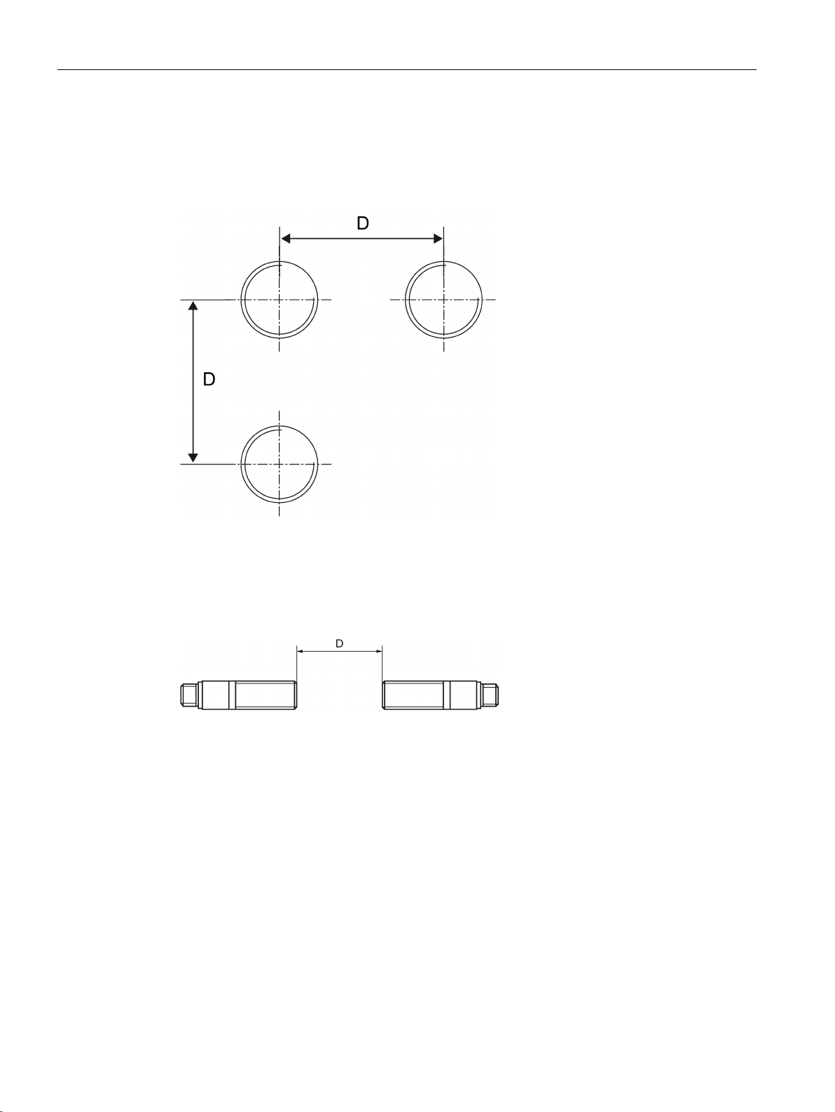
Readers
5.1.5
Minimum distance between RF210R readers
RF210R side by side
D
≥ 60 mm
RF210R face to face
D
≥ 100 mm
5.1 SIMATIC RF210R
Figure 5-1 Minimum distance between RF210R readers
Figure 5-2 Face-to-face distance between two RF210Rs
SIMATIC RF200
92 System Manual, 07/2015, J31069-D0227-U001-A9-7618
Page 93

Readers
5.1.6
Technical specifications of the RF210R reader
6GT2821-1AC10
Product type designation
SIMATIC RF210R
Radio frequencies
Operating frequency, rated value
13.56 MHz
Electrical data
Maximum range
20 mm
sponder (tag)
Typical transmission time for user data per byte
Baud rate
19200, 57600, 115200 Bd
Read/write distances of the reader
see section "Field data (Page 37)"
Interfaces
Electrical connector design
M8, 8-pin
Standard for interfaces for communication
RS-422
Antenna
integrated
Mechanical specifications
Housing
Supply voltage, current consumption, power loss
Supply voltage
24 VDC
5.1 SIMATIC RF210R
Table 5- 1 Technical specifications of the RF210R reader
Maximum data transmission rate reader ↔ tran-
• Read • approx. 1500 bytes/s
• Write • approx. 1500 bytes/s
• for write access • 0.6 ms
• for read access • 0.6 ms
ISO tags
• Material • Brass, nickel-plated
• Color • Silver
Recommended distance to metal 0 mm
Typical current consumption 50 mA
SIMATIC RF200
System Manual, 07/2015, J31069-D0227-U001-A9-7618
93
Page 94

Readers
6GT2821-1AC10
Permitted ambient conditions
Ambient temperature
Degree of protection to EN 60529
IP67
Shock-resistant to EN 60721-3-7, Class 7 M3
50 g
Vibration-resistant to EN 60721-3-7, Class 7 M3
20 g
Torsion and bending load
Not permitted
Design, dimensions and weights
Dimensions (Ø x H)
18 x 83 mm
Weight
65 g
Type of mounting
2 x nuts M18
Cable length for RS-422 interface, maximum
1000 m
(operating voltage, presence, error)
5.1.7
Approvals
FCC information
Siemens SIMATIC RF210R (MLFB 6GT2821-1AC10) FCC ID NXW-RF210R
Caution
Note
5.1 SIMATIC RF210R
• During operation • -20 … +70 °C
• During transportation and storage • -25 … +85 °C
LED display design 3-color LED
This device complies with part 15 of the FCC rules. Operation is subject to the following two
conditions:
(1) This device may not cause harmful interference, and
(2) this device must accept any interference received, including interference that may cause
undesired operation.
Any changes or modifications not expressly approved by the party responsible for
compliance could void the user's authority to operate the equipment.
This equipment has been tested and found to comply with the limits for a Class A digital
device, pursuant to part 15 of the FCC Rules.
These limits are designed to provide reasonable protection against harmful interference
when the equipment is operated in a commercial environment. This equipment generates,
uses, and can radiate radio frequency energy and, if not installed and used in accordance
with the instruction manual, may cause harmful interference to radio communications.
Operation of this equipment in a residential area is likely to cause harmful interference in
which case the user will be required to correct the interference at his own expense.
SIMATIC RF200
94 System Manual, 07/2015, J31069-D0227-U001-A9-7618
Page 95
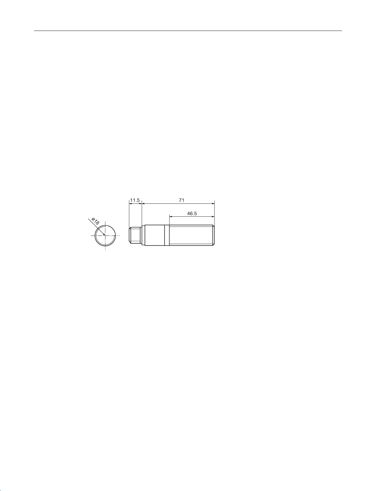
Readers
IC information
5.1.8
Dimension drawing
5.1 SIMATIC RF210R
This device complies with Industry Canada licence-exempt RSS standard(s). Operation is
subject to the following two conditions:
(1) This device may not cause interference, and
(2) this device must accept any interference, including interference that may cause
undesired operation of the device.
Le présent appareil est conforme aux CNR d`Industrie Canada applicables aux appareils
radio exempts de licence. L`exploitation est autorisée aux deux conditions suivantes :
(1) L`appareil ne doit pas produire de brouillage, et
(2) l'utilisateur de l`appareil doit accepter tout brouillage radioélectrique subi, même si le
brouillage est susceptible d`en compromettre le fonctionnement.
Figure 5-3 RF210R dimension drawing
Dimensions in mm
SIMATIC RF200
System Manual, 07/2015, J31069-D0227-U001-A9-7618
95
Page 96
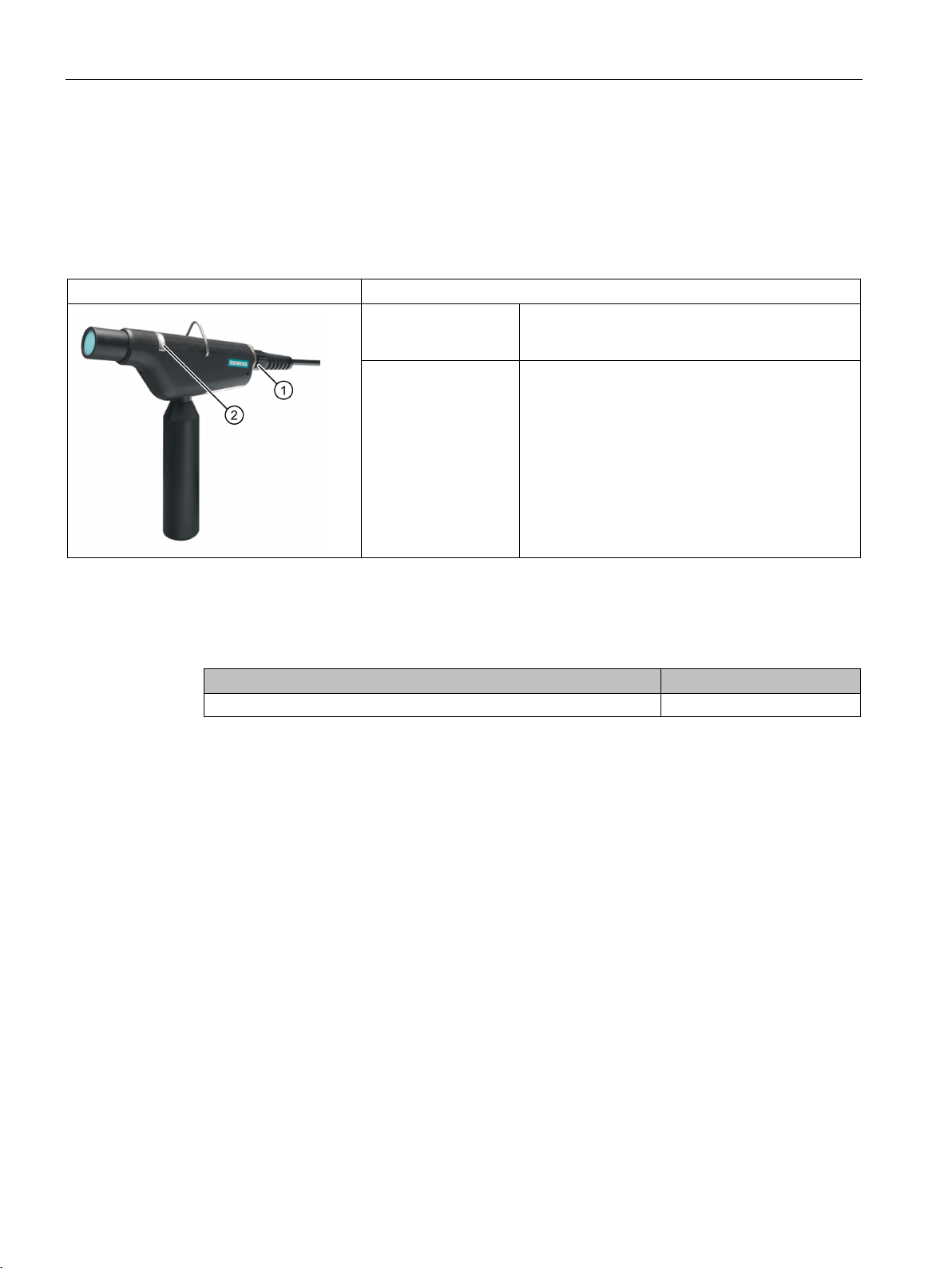
Readers
5.2
SIMATIC RF210M
5.2.1
Features
SIMATIC RF210M
Characteristics
②
5.2.2
Ordering data RF210M
Article number
RF210M with RS-422 interface (3964R)
6GT2823-0AA00
5.2 SIMATIC RF210M
Design
Application Reader for hand work and rework places, picking,
① RS422 interface
Status display
track and trace, tool Ident
SIMATIC RF200
96 System Manual, 07/2015, J31069-D0227-U001-A9-7618
Page 97
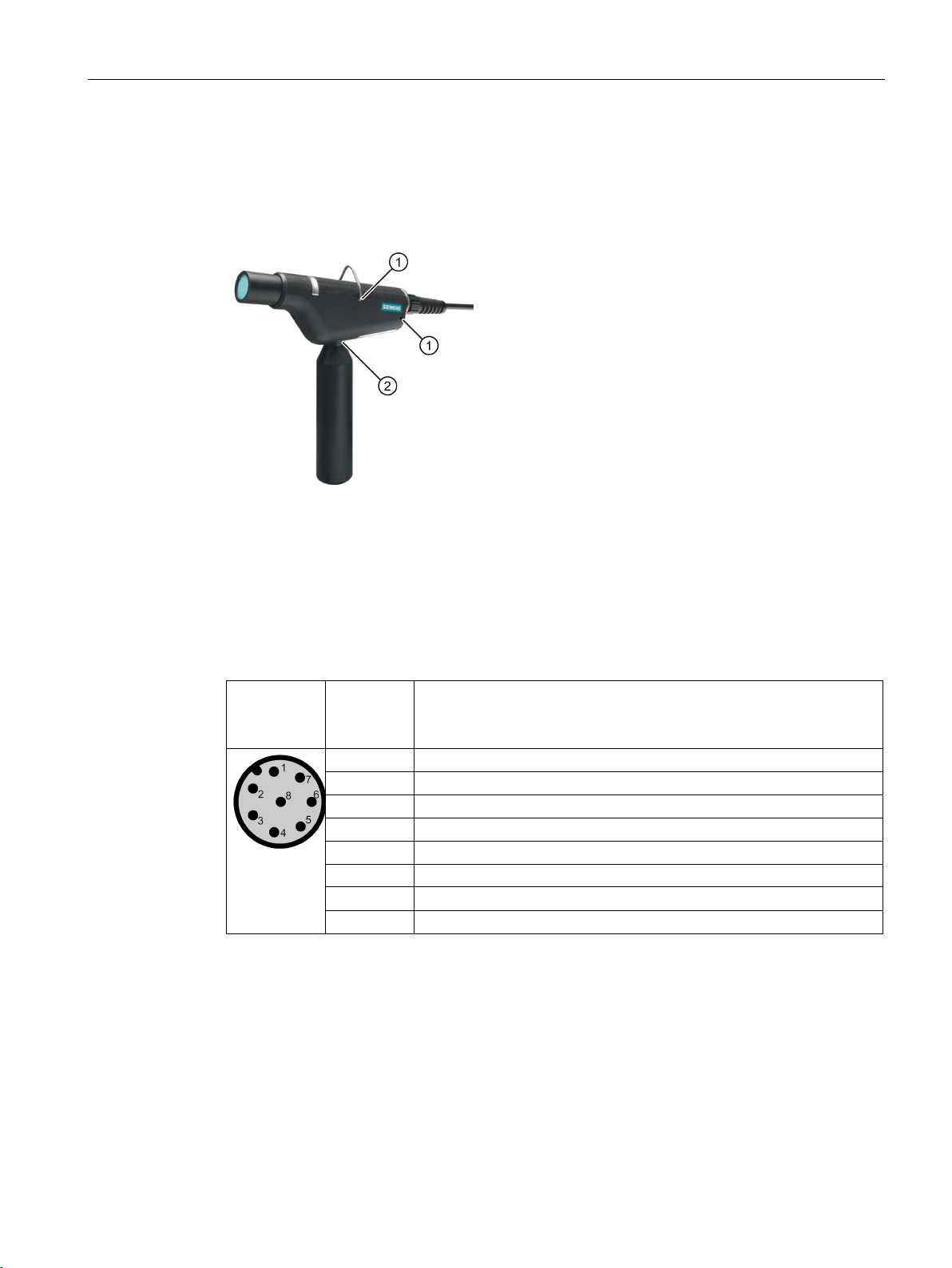
Readers
5.2.3
Installing the RF210M reader
①
Holes for mounting the suspension bracket
②
Thread for mounting the handle
5.2.4
Pin assignment RF210M with RS-422 interface
Pin
Pin
Device end
8-pin M12
Assignment
1
+ 24 V
2
- Transmit
3
0 V
4
+ Transmit
5
+ Receive
6
- Receive
8
Ground (shield)
5.2 SIMATIC RF210M
The following figure shows the completely mounted reader. Note that you can mount the
suspension bracket at two different points
recommend that you close the opening
①. If you do not mount the handle, we
② with the protective cap.
Figure 5-4 Installing the reader
7 Unassigned
SIMATIC RF200
System Manual, 07/2015, J31069-D0227-U001-A9-7618
97
Page 98

Readers
5.2.5
Display elements of the RF210M reader
Color
Meaning
flashing
Operating voltage present, reader not initialized or antenna switched off
lit
yellow1)
Transponder present
codes". The optical error display is only reset if the
(https://support.industry.siemens.com/cs/ww/en/view/44864850)).
1)
Only in the "with presence" mode.
5.2.6
Technical specifications of the RF210M reader
6GT2823-0AA00
Product type designation
SIMATIC RF210M
Radio frequencies
Operating frequency, rated value
13.56 MHz
Electrical data
Maximum range
20 mm
sponder (tag)
Typical transmission time for user data per byte
Baud rate
19200, 57600, 115200 Bd
Read/write distances of the reader
see section "Field data (Page 37)"
Interfaces
Electrical connector design
M8, 8-pin
Standard for interfaces for communication
RS-422
Antenna
integrated
5.2 SIMATIC RF210M
green
permanently
flashing red Error has occurred, the type of flashing corresponds to the error code in the
Operating voltage present, reader initialized and antenna switched on
table in the section "Error
corresponding reset parameter ("option_1 = 2") is set (see Product information "SIMATIC RF200 command set"
Table 5- 2 Technical specifications of the RF210M reader
Maximum data transmission rate reader ↔ tran-
• Read • approx. 1500 bytes/s
• Write • approx. 1500 bytes/s
• for write access • 0.6 ms
• for read access • 0.6 ms
ISO tags
SIMATIC RF200
98 System Manual, 07/2015, J31069-D0227-U001-A9-7618
Page 99

Readers
6GT2823-0AA00
Mechanical specifications
Housing
Supply voltage, current consumption, power loss
Supply voltage
24 VDC
Typical current consumption
50 mA
Permitted ambient conditions
Ambient temperature
Degree of protection to EN 60529
IP54
Shock-resistant to EN 60721-3-7, Class 7 M3
50 g
Vibration-resistant to EN 60721-3-7, Class 7 M3
20 g
Design, dimensions and weights
Dimensions
maximum working length 3.5 m
Weight
460 g
Type of mounting
Bracket for for hanging up
(operating voltage, presence, error)
5.2 SIMATIC RF210M
• Material • POM
• Color • Black
• During operation • -20 … +50 °C
• During transportation and storage • -25 … +60 °C
• Reader with handle (L x W x H)
• Reader without handle (L x W x H)
• Spiral connecting cable (L)
Cable length for RS-422 interface, maximum 1000 m
LED display design 3-color LED
195 x 26 x 140 mm
195 x 26 x 46 mm
2 m
SIMATIC RF200
System Manual, 07/2015, J31069-D0227-U001-A9-7618
99
Page 100

Readers
5.2.7
Approvals
FCC information
Siemens SIMATIC RF210R (MLFB 6GT2821-1AC10) FCC ID NXW-RF210R
Caution
Note
IC information
5.2 SIMATIC RF210M
This device complies with part 15 of the FCC rules. Operation is subject to the following two
conditions:
(1) This device may not cause harmful interference, and
(2) this device must accept any interference received, including interference that may cause
undesired operation.
Any changes or modifications not expressly approved by the party responsible for
compliance could void the user's authority to operate the equipment.
This equipment has been tested and found to comply with the limits for a Class A digital
device, pursuant to part 15 of the FCC Rules.
These limits are designed to provide reasonable protection against harmful interference
when the equipment is operated in a commercial environment. This equipment generates,
uses, and can radiate radio frequency energy and, if not installed and used in accordance
with the instruction manual, may cause harmful interference to radio communications.
Operation of this equipment in a residential area is likely to cause harmful interference in
which case the user will be required to correct the interference at his own expense.
This device complies with Industry Canada licence-exempt RSS standard(s). Operation is
subject to the following two conditions:
(1) This device may not cause interference, and
(2) this device must accept any interference, including interference that may cause
undesired operation of the device.
Le présent appareil est conforme aux CNR d`Industrie Canada applicables aux appareils
radio exempts de licence. L`exploitation est autorisée aux deux conditions suivantes :
(1) L`appareil ne doit pas produire de brouillage, et
(2) l'utilisateur de l`appareil doit accepter tout brouillage radioélectrique subi, même si le
brouillage est susceptible d`en compromettre le fonctionnement.
SIMATIC RF200
100 System Manual, 07/2015, J31069-D0227-U001-A9-7618
 Loading...