

Siemens SIMATIC HMI KTP700 Basic, SIMATIC HMI KTP900 Basic, SIMATIC HMI KTP1200 Basic DP, SIMATIC HMI KTP700 Basic DP, SIMATIC HMI KTP1200 Basic Basic Operating Instructions Manual
Page 1

___________________
___________________
___________________
___________________
___________________
___________________
___________________
___________________
___________________
___________________
___________________
SIMATIC HMI
HMI devices
Basic Panels 2nd Generation
Operating Instructions
10/2016
A5E33293231
Preface
Overview
1
Safety instructions
2
Mounting and connecting
3
Operating the device
4
Configuring the device
5
Commissioning a project
6
Maintenance and care
7
Technical specifications
8
Technical Support
A
Abbreviations
B
-AB
Page 2
Siemens AG
Division Digital Factory
Postfach 48 48
90026 NÜRNBERG
GERMANY
A5E33293231-AB
Ⓟ
Copyright © Siemens AG 2016.
All rights reserved
Legal information
Warning notice system
DANGER
indicates that death or severe personal injury will result if proper precautions are not taken.
WARNING
indicates that death or severe personal injury may result if proper precautions are not taken.
CAUTION
indicates that minor personal injury can result if proper precautions are not taken.
NOTICE
indicates that property damage can result if proper precautions are not taken.
Qualified Personnel
personnel qualified
Proper use of Siemens products
WARNING
Siemens products may only be used for the applications described in the catalog and in the relevant technical
ambient conditions must be complied with. The information in the relevant documentation must be observed.
Trademarks
Disclaimer of Liability
This manual contains notices you have to observe in order to ensure your personal safety, as well as to prevent
damage to property. The notices referring to your personal safety are highlighted in the manual by a safety alert
symbol, notices referring only to property damage have no safety alert symbol. These notices shown below are
graded according to the degree of danger.
If more than one degree of danger is present, the warning notice representing the highest degree of danger will
be used. A notice warning of injury to persons with a safety alert symbol may also include a warning relating to
property damage.
The product/system described in this documentation may be operated only by
task in accordance with the relevant documentation, in particular its warning notices and safety instructions.
Qualified personnel are those who, based on their training and experience, are capable of identifying risks and
avoiding potential hazards when working with these products/systems.
Note the following:
documentation. If products and components from other manufacturers are used, these must be recommended
or approved by Siemens. Proper transport, storage, installation, assembly, commissioning, operation and
maintenance are required to ensure that the products operate safely and without any problems. The permissible
All names identified by ® are registered trademarks of Siemens AG. The remaining trademarks in this publication
may be trademarks whose use by third parties for their own purposes could violate the rights of the owner.
We have reviewed the contents of this publication to ensure consistency with the hardware and software
described. Since variance cannot be precluded entirely, we cannot guarantee full consistency. However, the
information in this publication is reviewed regularly and any necessary corrections are included in subsequent
editions.
for the specific
11/2016 Subject to change
Page 3

Preface
Purpose of the operating instructions
Target group
Chapter
All
Operators
the process control phase.
Commissioning engineers
section "Maintenance and servicing."
Service technicians
"Maintenance and servicing."
Maintenance technicians
maintenance work during the process control phase.
These operating instructions provide information based on the requirements defined by
IEC 62079 for documentation. This information relates to the HMI device, its storage,
transportation, place of use, installation, use and maintenance.
These operating instructions are intended for a variety of target groups. The following table
shows the chapters of these operating instructions that are of particular importance for the
respective target group.
"Safety instructions"
The operator operates and monitors the system during
"Overview"
"Operating the device"
The commissioning engineer integrates the HMI device
into the system and ensures the operating capability of
the HMI device for the process control phase.
Service technicians rectify faults that occur during the
process control phase.
Maintenance technicians carry out servicing and
The information system of WinCC contains additional information. The information system is
integrated as online help in WinCC and contains instructions, examples and reference
information in electronic form.
All chapters.
Depending on the use of the HMI device,
certain chapters may not be of relevance to
the commissioning engineer, e.g. the
All chapters.
Depending on the use of the HMI device,
certain chapters may not be of relevance to
the service technicians, e.g. the section
Maintenance and care
Basic Panels 2nd Generation
Operating Instructions, 10/2016, A5E33293231-AB
3
Page 4
Preface
Scope
Device designation
SIMATIC HMI
Device type
Interface type
Can be configured with
KTP400 Basic
PROFINET
KTP700 Basic DP
PROFIBUS
KTP900 Basic
PROFINET
KTP1200 Basic
PROFINET
KTP1200 Basic DP
PROFIBUS
1
higher.
Basic knowledge required
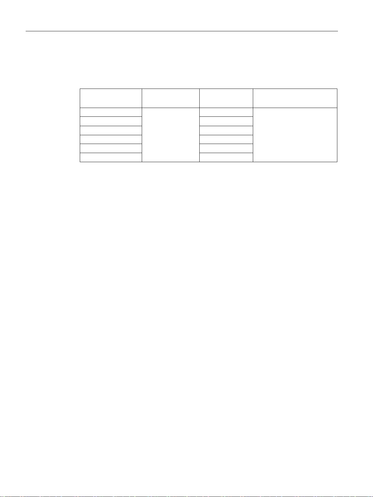
These operating instructions are valid for all versions of the SIMATIC HMI Basic Panels. The
following naming conventions apply:
KTP700 Basic PROFINET
Devices are configurable as of WinCC V13. The description in this manual relates to V14 or
Knowledge of automation technology and process communication is necessary to
understand the operating instructions.
An understanding of the use of computers and operating systems is also required.
Touch device with
function keys
WinCC (TIA Portal) as of V13 1
Basic Panels 2nd Generation
4 Operating Instructions, 10/2016, A5E33293231-AB
Page 5
Preface
Illustrations and text highlighting
Graphical highlighting
Description
in the figures as a representation of
Text highlighting
Scope
commands
<F1>
Keyboard operation
This manual contains figures of the described devices. The figures may deviate from the
supplied device in certain details.
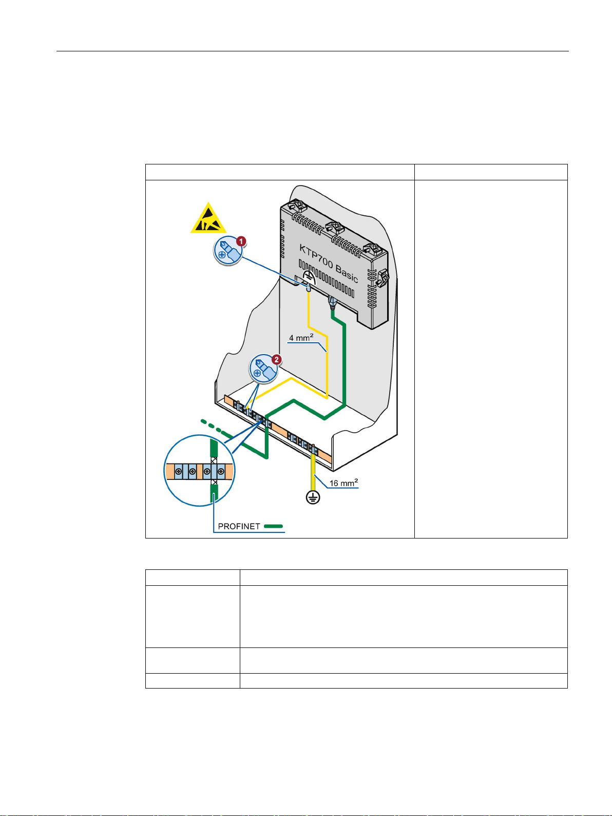
The following graphical highlighting facilitates reading these operating instructions:
If the instructions involve several
tasks, the individual tasks are
highlighted by a red number circle.
A light blue highlight indicates
components and tools that are
required in the course of a task.
KTP700 Basic is sometimes shown
all Basic Panels.
Basic Panels 2nd Generation
Operating Instructions, 10/2016, A5E33293231-AB
The following text highlighting facilitates reading these operating instructions:
"Add screen"
"File > Edit" Operational sequences, for example, menu commands, shortcut menu
• Terms that appear in the user interface, for example, dialog names, tabs,
buttons, menu commands
• Input values, for example, limits, tag values
• Path information
5
Page 6

Preface
Note
A note contains important information on described products and their handling or on a
section of this documentation.
Names of the software
Names of the hardware
Trademarks
Note information highlighted as follows:
Configuration and runtime software have different names as follows:
● "WinCC (TIA Portal) V13", for example, refers to the configuration software.
The term "WinCC" is used in a general context. The full name is always used when it is
necessary to differentiate between different versions of the configuration software.
● "WinCC Runtime" refers to the runtime software that can run on HMI devices.
These operating instructions describe the new "Basic Panels 2nd Generation" which
replaces the current Basic Panels. The term "Basic Panel" is used synonymously for a
"Basic Panel 2nd Generation" in these instructions.
Names labeled with a ® symbol are registered trademarks of the Siemens AG. Other names
used in this documentation may be trademarks, the use of which by third parties for their
own purposes could violate the rights of the owner.
®
● HMI
● SIMATIC
● SIMATIC HMI
● WinCC
®
®
®
Basic Panels 2nd Generation
6 Operating Instructions, 10/2016, A5E33293231-AB
Page 7

Table of contents
Preface ................................................................................................................................................... 3
1 Overview............................................................................................................................................... 11
2 Safety instructions ................................................................................................................................. 17
3 Mounting and connecting ...................................................................................................................... 21
4 Operating the device ............................................................................................................................. 39
1.1 Product overview .................................................................................................................... 11
1.2 Design of the PROFINET devices .......................................................................................... 12
1.3 Design of the PROFIBUS devices .......................................................................................... 13
1.4 Scope of delivery .................................................................................................................... 14
1.5 Accessories ............................................................................................................................. 15
2.1 General safety instructions ..................................................................................................... 17
2.2 Notes about usage .................................................................................................................. 19
3.1 Preparations ............................................................................................................................ 21
3.1.1 Checking the package contents .............................................................................................. 21
3.1.2 Checking the operating conditions .......................................................................................... 21
3.1.3 Selecting a mounting position ................................................................................................. 22
3.1.4 Checking clearances............................................................................................................... 23
3.1.5 Making the mounting cutout .................................................................................................... 24
3.2 Mounting the HMI device ........................................................................................................ 25
3.3 Connecting the HMI device ..................................................................................................... 27
3.3.1 Connection sequence ............................................................................................................. 27
3.3.2 Connecting the equipotential bonding circuit .......................................................................... 28
3.3.3 Connecting the power supply ................................................................................................. 29
3.3.4 Connecting a programming device ......................................................................................... 31
3.3.5 Connecting the configuration PC ............................................................................................ 31
3.3.6 Connecting the controller ........................................................................................................ 33
3.3.7 Connecting a USB device ....................................................................................................... 35
3.4 Switching on and testing the HMI device ................................................................................ 36
3.5 Securing the cables ................................................................................................................ 38
4.1 Overview ................................................................................................................................. 39
4.2 General functions of the screen keyboard .............................................................................. 41
4.3 The screen keyboards ............................................................................................................ 42
4.4 Entering data ........................................................................................................................... 46
Basic Panels 2nd Generation
Operating Instructions, 10/2016, A5E33293231-AB
7
Page 8

Table of contents
5 Configuring the device .......................................................................................................................... 47
6 Commissioning a project ....................................................................................................................... 73
5.1 Opening the settings .............................................................................................................. 47
5.2 Overview of functions ............................................................................................................. 49
5.3 Save to external storage medium – Backup .......................................................................... 50
5.4 Restore from external storage medium – Restore ................................................................. 51
5.5 Load project from external storage medium .......................................................................... 52
5.6 Update operating system from external storage medium ...................................................... 53
5.7 Changing the IP address and device name of a controller .................................................... 54
5.8 Editing communication connections....................................................................................... 55
5.9 Configuring the time server .................................................................................................... 56
5.10 Enter time and date ................................................................................................................ 57
5.11 Activating the acoustic signal ................................................................................................. 58
5.12 Configuring Autostart or wait time .......................................................................................... 59
5.13 Changing the password settings ............................................................................................ 60
5.14 Displaying licensing information for the HMI device .............................................................. 61
5.15 Displaying information about the HMI device ........................................................................ 62
5.16 Change network settings of PROFINET devices ................................................................... 63
5.17 Change network settings of PROFIBUS devices ................................................................... 64
5.18 Assigning transfer parameters ............................................................................................... 65
5.19 Configure Sm@rt Server ........................................................................................................ 66
5.20 Importing a certificate via USB ............................................................................................... 67
5.21 Displaying and deleting certificates ....................................................................................... 68
5.22 Calibrating the touch screen .................................................................................................. 69
5.23 Changing the monitor settings ............................................................................................... 70
5.24 Setting the screen saver ........................................................................................................ 71
6.1 Overview ................................................................................................................................ 73
6.2 Operating modes.................................................................................................................... 74
6.3 Data transmission options ...................................................................................................... 75
6.4 Transfer .................................................................................................................................. 75
6.4.1 Overview ................................................................................................................................ 75
6.4.2 Starting the manual transfer ................................................................................................... 75
6.4.3 Starting the transfer automatically ......................................................................................... 77
6.4.4 Testing a project..................................................................................................................... 78
Basic Panels 2nd Generation
8 Operating Instructions, 10/2016, A5E33293231-AB
Page 9

Table of contents
7 Maintenance and care ........................................................................................................................... 95
8 Technical specifications ........................................................................................................................ 97
6.5 Backup and restore ................................................................................................................. 80
6.5.1 Overview ................................................................................................................................. 80
6.5.2 Backup and restore using ProSave ........................................................................................ 81
6.5.3 Backup and restore using WinCC ........................................................................................... 82
6.6 Updating the operating system - Basic Panel DP ................................................................... 83
6.6.1 Overview ................................................................................................................................. 83
6.6.2 Resetting the factory settings ................................................................................................. 84
6.6.3 Updating the operating system using ProSave ...................................................................... 84
6.7 Updating the operating system - Basic Panel with PROFINET interface ............................... 85
6.7.1 Overview ................................................................................................................................. 85
6.7.2 Resetting the factory settings ................................................................................................. 86
6.7.3 Updating the operating system using ProSave ...................................................................... 87
6.7.4 Updating the operating system using WinCC ......................................................................... 88
6.7.5 Resetting to factory settings with ProSave ............................................................................. 89
6.7.6 Resetting to factory settings with WinCC................................................................................ 90
6.8 Reset to factory settings via USB ........................................................................................... 91
6.9 Managing WinCC options ....................................................................................................... 92
6.10 Transferring a license key ....................................................................................................... 93
7.1 Maintenance and care ............................................................................................................ 95
7.2 Recycling ................................................................................................................................ 96
8.1 Certificates and approvals ...................................................................................................... 97
8.2 Electromagnetic compatibility ................................................................................................. 99
8.2.1 Emitted interference ................................................................................................................ 99
8.2.2 Immunity to interferences ....................................................................................................... 99
8.3 Mechanical ambient conditions ............................................................................................... 99
8.3.1 Transport and storage conditions ........................................................................................... 99
8.3.2 Operating Conditions .............................................................................................................. 99
8.4 Climatic ambient conditions .................................................................................................. 100
8.4.1 Long-term storage ................................................................................................................. 100
8.4.2 Transport and short-term storage ......................................................................................... 100
8.4.3 Operating Conditions ............................................................................................................ 101
8.4.4 Climate diagram .................................................................................................................... 101
8.5 Information on insulation tests, protection class and degree of protection........................... 102
8.6 Dimension drawings .............................................................................................................. 103
8.6.1 Dimensional drawing of KTP400 Basic................................................................................. 103
8.6.2 Dimensional drawing of KTP700 Basic................................................................................. 104
8.6.3 Dimensional drawing of KTP700 Basic DP .......................................................................... 105
8.6.4 Dimensional drawing of KTP900 Basic................................................................................. 106
8.6.5 Dimension drawings of KTP1200 Basic................................................................................ 107
8.6.6 Dimensional drawing of KTP1200 Basic DP ........................................................................ 108
Basic Panels 2nd Generation
Operating Instructions, 10/2016, A5E33293231-AB
9
Page 10

Table of contents
A Technical Support ................................................................................................................................ 119
B Abbreviations ....................................................................................................................................... 121
Glossary .............................................................................................................................................. 123
Index ................................................................................................................................................... 129
8.7 Technical specifications ....................................................................................................... 109
8.7.1 Power supply ........................................................................................................................ 109
8.7.2 KTP400 Basic, KTP700 Basic and KTP700 Basic DP ........................................................ 109
8.7.3 KTP900 Basic, KTP1200 Basic and KTP1200 Basic DP .................................................... 111
8.8 Interface description ............................................................................................................. 113
8.8.1 Power supply ........................................................................................................................ 113
8.8.2 PROFIBUS (Sub-D RS422/485) .......................................................................................... 113
8.8.3 PROFINET (LAN)................................................................................................................. 114
8.8.4 USB ...................................................................................................................................... 114
8.9 Scope of functions with WinCC ............................................................................................ 115
A.1 Service and support ............................................................................................................. 119
A.2 System events...................................................................................................................... 120
Basic Panels 2nd Generation
10 Operating Instructions, 10/2016, A5E33293231-AB
Page 11

1
1.1
Product overview
The beauty of simplicity
New, cost-efficient HMI generation meets the trend for high-quality visualization even in
small machines and plants
Siemens meets the requirements of users for high-quality visualization and operation even in
small and medium-size machines and plants with the second generation of SIMATIC HMI
Basic Panels. While the price of the new devices is based on the current panels, their scope
of performance has been expanded tremendously. The high resolution and a color depth of
up to 65,500 colors are major factors contributing to the increased performance.
Even the connectivity either by PROFINET or PROFIBUS interface plus USB port could be
significantly improved. Configuration and operation of the new panels has become easier in
connection with simplified programming by means of the new WinCC software version in the
TIA Portal.
Basic Panels 2nd Generation
Operating Instructions, 10/2016, A5E33293231-AB
11
Page 12
Overview
1.2
Design of the PROFINET devices
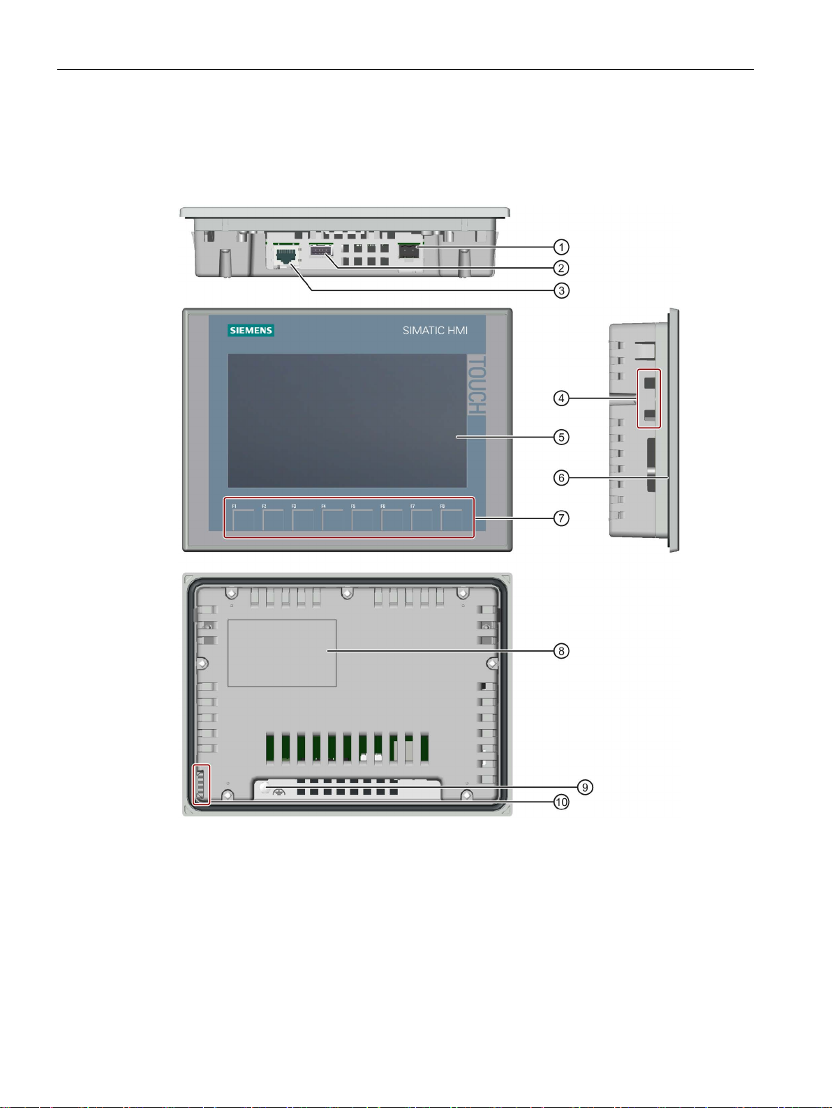
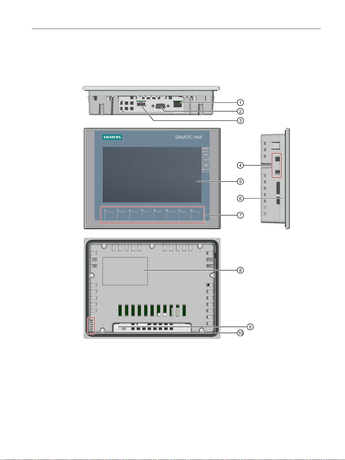
①
Power supply connection
⑥
Mounting seal
②
USB port
⑦
Function keys
③
PROFINET interface
⑧
Rating plate
④
Recesses for a mounting clip
⑨
Connection for functional ground
⑤
Display/touch screen
⑩
Guide for labeling strips
1.2 Design of the PROFINET devices
The figure below shows the design of the PROFINET devices using KTP700 Basic as an
example.
Basic Panels 2nd Generation
12 Operating Instructions, 10/2016, A5E33293231-AB
Page 13
Overview
1.3
Design of the PROFIBUS devices
①
Power supply connection
⑥
Mounting seal
②
RS 422/RS 485 port
⑦
Function keys
③
USB port
⑧
Rating plate
④
Recesses for a mounting clip
⑨
Functional earth connection
⑤
Display/touch screen
⑩
Guides for labeling strips
1.3 Design of the PROFIBUS devices
The figure below shows the design of the PROFIBUS devices using KTP700 Basic DP as an
example.
Basic Panels 2nd Generation
Operating Instructions, 10/2016, A5E33293231-AB
13
Page 14
Overview
1.4
Scope of delivery
Name
Figure
Quantity
1.4 Scope of delivery
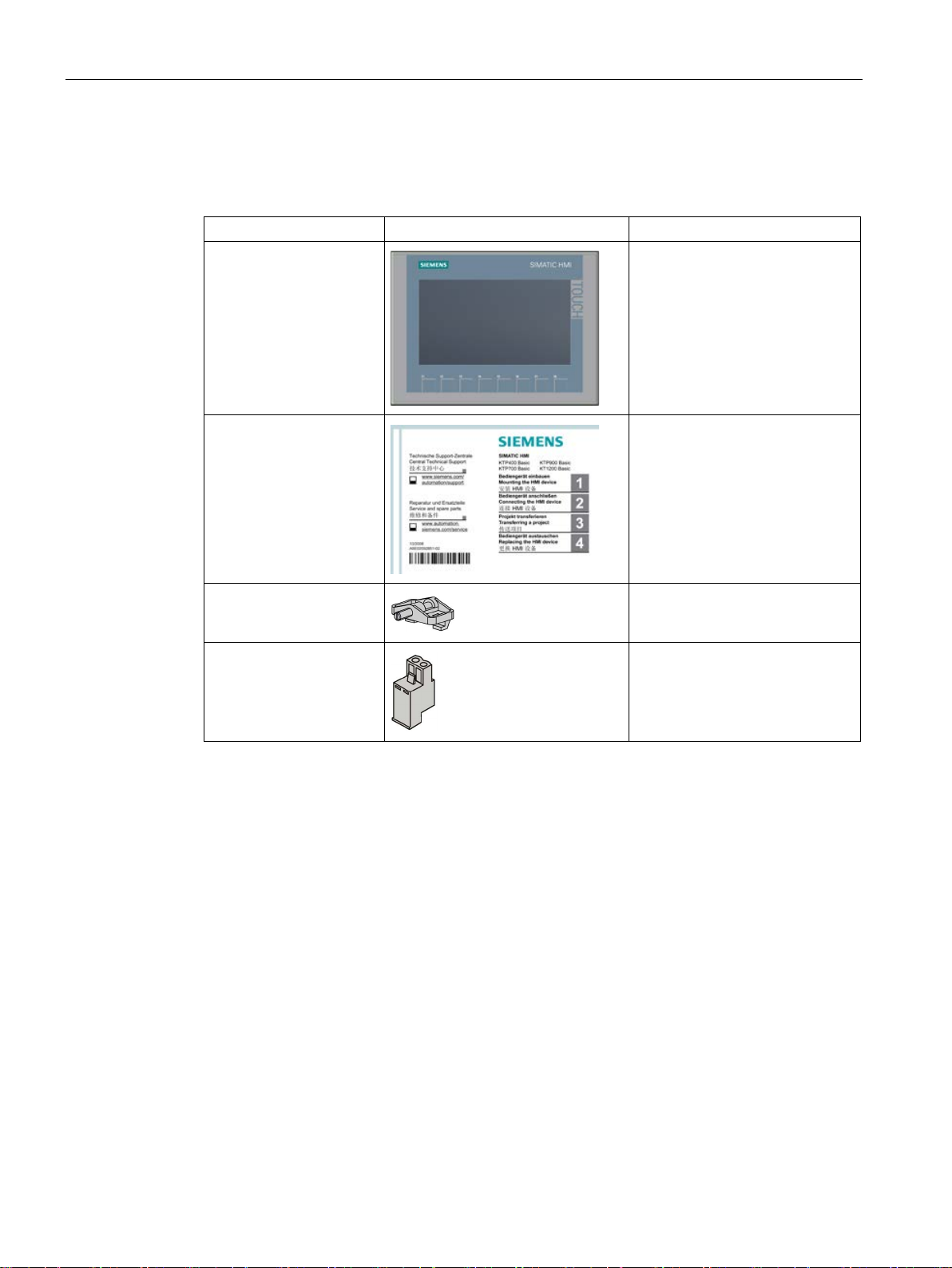
The scope of delivery of the HMI device includes the following components:
HMI device
Quick Installation Guide
Mounting clips with
grub screw
Power supply connector
1
1
According to the quantity required
for mounting, in accessory kit
1, in accessory kit
Basic Panels 2nd Generation
14 Operating Instructions, 10/2016, A5E33293231-AB
Page 15

Overview
1.5
Accessories
Storage media and I/O devices
Name
Article number
SIMATIC PC USB flash drive
6ES7648-0DC50-0AA0
Converters, adapters and connectors
Name
Purpose
Article number
converter
Basic Panels DP
90 degree elbow adapter
For RS 422/RS 485 port, cable outlet to rear
6AV6671-8XD00-0AX0
straight cable outlet
"IE FC RJ45 Plug 2x2"
Protective films
Name
Purpose
Article number
Protective film 4"
Protective film set for KTP400 Basic
6AV2124-6DJ00-0AX0
KTP700 Basic DP
Protective film 9"
Protective film set for KTP900 Basic
6AV2181-3JJ20-0AX0
KTP1200 Basic DP
Service packages
Name
Article number
Set of 20 mounting clips
6AV6671-8KX00-0AX2
Set of 10 power supply connectors
6AV6671-8XA00-0AX0
1.5 Accessories
Accessories are not included in the HMI device scope of delivery, but can be ordered on the
Internet under Industry Mall (https://mall.industry.siemens.com
).
This section contains the number of accessories available at the time of publication of the
operating instructions.
Industrial USB Hub 4 6AV6671-3AH00-0AX0
RS 422 to RS 232
PROFIBUS connector Recommended PROFIBUS connector with
PROFINET RJ45
connector
Protective film 7" Protective film set for KTP700 Basic and
Protective film 12" Protective film set for KTP1200 Basic and
Connection of third-party controllers to
Required for connection of Basic Panels with
PROFINET interface to PROFINET
6AV6671-8XE00-0AX0
6GK1500-0FC10
6GK1901-1BB10-2AA0
6AV2124-6GJ00-0AX0
6AV2181-3MJ20-0AX0
Basic Panels 2nd Generation
Operating Instructions, 10/2016, A5E33293231-AB
15
Page 16

Overview
Other accessories
1.5 Accessories
Additional USB accessories can be found on the Internet in the following entry:
FAQ 19188460 (https://support.industry.siemens.com/cs/ww/en/view/19188460
)
Basic Panels 2nd Generation
16 Operating Instructions, 10/2016, A5E33293231-AB
Page 17
2
2.1
General safety instructions
Working on the control cabinet
WARNING
Open equipment
Dangerous voltage
Installation as intended
WARNING
Installation only in machinery that conforms to the machinery directive
The HMI device is an open equipment. This means the HMI device may only be installed in
cubicles or cabinets that provide front panel access for operating the device.
The cubicle or cabinet in which the HMI device is installed may only be accessed with a key
or tool and only by trained, authorized personnel.
Opening the cabinet will expose high voltage parts. Contact with these parts could be fatal.
Always disconnect the cabinet from the mains before opening it.
You are not permitted to commission the HMI device unless it has been verified that the
machine in which the HMI device is to be installed complies with directive 2006/42/EC.
Basic Panels 2nd Generation
Operating Instructions, 10/2016, A5E33293231-AB
17
Page 18
Safety instructions
Strong high-frequency radiation
NOTICE
Observe immunity to high-frequency radiation
ESD
Industrial Security
2.1 General safety instructions
The device has an increased immunity to high frequency radiation according to the
specifications on electromagnetic compatibility in the technical specifications.
Radiation exposure in excess of the specified immunity limits can impair device functions
and result in malfunctions and therefore injuries or damage.
Read the information on immunity to high frequency radiation in the technical specifications.
An electrostatically sensitive device is equipped with electronic components. Due to their
design, electronic components are sensitive to overvoltage and thus to the discharge of
static electricity. Note the corresponding regulations when handling ESD.
Siemens provides products and solutions with industrial security functions that support the
secure operation of plants, systems, machines and networks.
In order to protect plants, systems, machines and networks against cyber threats, it is
necessary to implement – and continuously maintain – a holistic, state-of-the-art industrial
security concept. Siemens’ products and solutions only form one element of such a concept.
Customer is responsible to prevent unauthorized access to its plants, systems, machines
and networks. Systems, machines and components should only be connected to the
enterprise network or the internet if and to the extent necessary and with appropriate security
measures (e.g. use of firewalls and network segmentation) in place.
Additionally, Siemens’ guidance on appropriate security measures should be taken into
account. For more information about industrial security, please visit
(http://www.siemens.com/industrialsecurity
).
Siemens’ products and solutions undergo continuous development to make them more
secure. Siemens strongly recommends to apply product updates as soon as available and to
always use the latest product versions. Use of product versions that are no longer supported,
and failure to apply latest updates may increase customer’s exposure to cyber threats.
To stay informed about product updates, subscribe to the Siemens Industrial Security RSS
Feed under (http://www.siemens.com/industrialsecurity
).
Basic Panels 2nd Generation
18 Operating Instructions, 10/2016, A5E33293231-AB
Page 19
Safety instructions
Disclaimer for third-party software updates
Notes on protecting administrator accounts
2.2
Notes about usage
NOTICE
The HMI device is approved for indoor use only.
Industrial applications
Use in residential areas
Note
The HMI device is not intended for use in residential areas. Operation of an HMI device in
residential areas can have a negative influence on radio/TV reception.
2.2 Notes about usage
This product includes third-party software. Siemens AG only provides a warranty for
updates/patches of the third-party software, if these have been distributed as part of a
Siemens software update service contract or officially released by Siemens AG. Otherwise,
updates/patches are undertaken at your own risk. You can find more information about our
Software Update Service offer on the Internet at Software Update Service
http://www.automation.siemens.com/mcms/automation-software/en/software-update-
(
service).
A user with administrator privileges has extensive access and manipulation options in the
system.
Therefore, ensure there are adequate safeguards for protecting the administrator accounts
to prevent unauthorized changes. To do this, use secure passwords and a standard user
account for normal operation. Other measures, such as the use of security policies, should
be applied as needed.
The HMI device may be damaged if it is operated outdoors.
Operate the HMI device indoors only.
The HMI device is designed for industrial applications. It conforms to the following standards:
● Requirements of the emission standard for industrial environments,
EN 61000-6-4: 2007 + A1:2011
● ESD immunity requirements to DIN EN 61000-6-2:2005
If the HMI device is used in a residential area, you must ensure compliance with the limits in
technical standard EN 61000-6-3 regarding the emission of radio frequency interference.
Individual acceptance is required.
Basic Panels 2nd Generation
Operating Instructions, 10/2016, A5E33293231-AB
19
Page 20

Safety instructions
Use with additional measures
Notes on communication
Note
Communication errors caused by address conflict
Communication errors can occur if several devices in a network share the same bus address
or IP address.
Make sure that your HMI device is assigned a unique address in the network.
Note
Updating tag values following a communication error
If communication between an HMI device and controller is interrupted, all tag values
displayed on the HMI device will be replaced by a hash mark ("#").
When the communication between the HMI device and controller is restored, all tag values
will be u
Ethernet communication with Basic Panels with PROFINET interface
Basic Panels with PROFINET interface support the following types of communication:
•
•
2.2 Notes about usage
The HMI device should not be used at the following locations unless additional measures are
taken:
● In locations with a high degree of ionizing radiation
● In locations with severe operating conditions, for example, due to:
– Corrosive vapors, gases, oils or chemicals
– Strong electrical or magnetic fields of high intensity
● In systems that require special monitoring, for example, in:
– Elevators
– Systems in especially hazardous rooms
pdated immediately. The cycle time for updating the tag values begins again at "0".
PROFINET basic function for commissioning and diagnostics
Standard Ethernet communication
Basic Panels 2nd Generation
20 Operating Instructions, 10/2016, A5E33293231-AB
Page 21

3
3.1
Preparations
3.1.1
Checking the package contents
Note
Damaged parts
Do not install parts damaged during shipment. In the case of damaged parts, contact your
Siemens representative.
3.1.2
Checking the operating conditions
Check the package content for visible signs of transport damage and for completeness.
The package content is described in section Scope of delivery (Page 14).
Keep the provided documentation in a safe place. The documentation is part of the HMI
device and is required for subsequent commissioning.
Note the information in the following sections of these operating instructions before installing
the HMI device:
● Certificates and approvals (Page 97)
● Electromagnetic compatibility (Page 99)
● Mechanical ambient conditions (Page 99)
● Climatic ambient conditions (Page 100)
● Information on insulation tests, protection class and degree of protection (Page 102)
● Technical specifications (Page 109)
Basic Panels 2nd Generation
Operating Instructions, 10/2016, A5E33293231-AB
21
Page 22
Mounting and connecting
3.1.3
Selecting a mounting position
NOTICE
Damage due to overheating
Mounting position
Mounting in horizontal format
3.1 Preparations
The device is suitable for installation in:
● Mounting cabinets
● Control cabinets
● Switchboards
● Consoles
In the following, all of these mounting options are referred to by the general term "cabinet".
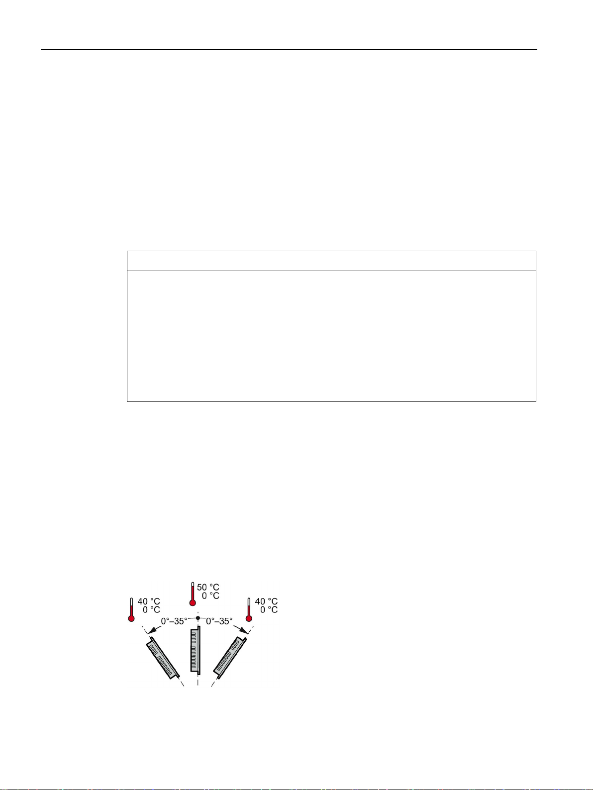
The device is self-ventilated and approved for inclined mounting at angles up to +/-35° from
the vertical in stationary cabinets.
Inclined installation reduces the convection by the device and therefore the maximum
permitted ambient temperature for operation.
If there is sufficient forced ventilation, the device can also be operated in the inclined
mounting position up to the maximum permitted ambient temperature for vertical
installation. The device may otherwise be damaged and its certifications and warranty will
be rendered null and void.
The ambient temperature ranges listed in this section apply to the temperature inside the
cabinet.
Select one of the approved mounting positions for your device. The approved mounting
positions are described in the following sections.
Ambient temperature in the cabinet with horizontal mounting:
● Vertical mounting (0° inclined): Maximum +50 °C
● Inclined mounting (inclined up to 35°): Maximum +40 °C
Basic Panels 2nd Generation
22 Operating Instructions, 10/2016, A5E33293231-AB
Page 23
Mounting and connecting
Mounting in vertical format
See also
3.1.4
Checking clearances
3.1 Preparations
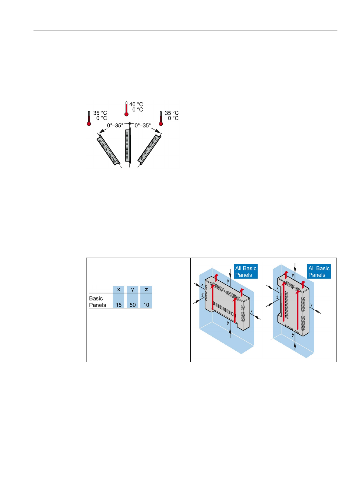
Ambient temperature in the cabinet with vertical mounting:
● Vertical mounting (0° inclined): Maximum +40 °C
● Inclined mounting (inclined up to 35°): Maximum +35 °C
Operating Conditions (Page 101)
The following clearances are required around the HMI device to ensure sufficient selfventilation:
Required clearance around the
HMI devices.
All dimensions in mm
Basic Panels 2nd Generation
Operating Instructions, 10/2016, A5E33293231-AB
23
Page 24

Mounting and connecting
3.1.5
Making the mounting cutout
Note
Stability of the mounting cutout
The material in the area of the mounting
lasting and safe mounting of the HMI device.
To achieve the degrees of protection described below, it must be ensured that deformation
of the material cannot occur due to the force of the mounting clips
Degrees of protection
Mounting compatibility
Mounting cutout Basic Panel
Compatible with the mounting cutouts of the HMI device
KTP400 Basic
KTP400 Basic color PN
KTP700 Basic, KTP700 Basic DP
KTP600 Basic color PN; TP700 Comfort
KTP900 Basic
TP900 Comfort
KTP1200 Basic, KTP1200 Basic DP
TP1200 Comfort
3.1 Preparations
cutout must provide sufficient strength to guarantee
or operation of the device.
The degrees of protection of the HMI device can only be guaranteed if the following
requirements are met:
● Material thickness at the mounting cutout for a protection rating of IP65 or Front face only
Type 4X/Type 12 (indoor use only): 2 mm to 6 mm.
● Permitted deviation from plane at the mounting cutout: ≤ 0.5 mm
This condition must be met for the mounted HMI device.
● Permitted surface roughness in the area of the mounting seal: ≤ 120 µm (R
The mounting cutouts of the Basic panels are compatible with the mounting cutouts of the
following SIMATIC HMI devices:
120)
z
Basic Panels 2nd Generation
24 Operating Instructions, 10/2016, A5E33293231-AB
Page 25
Mounting and connecting
Dimensions of the mounting cutout
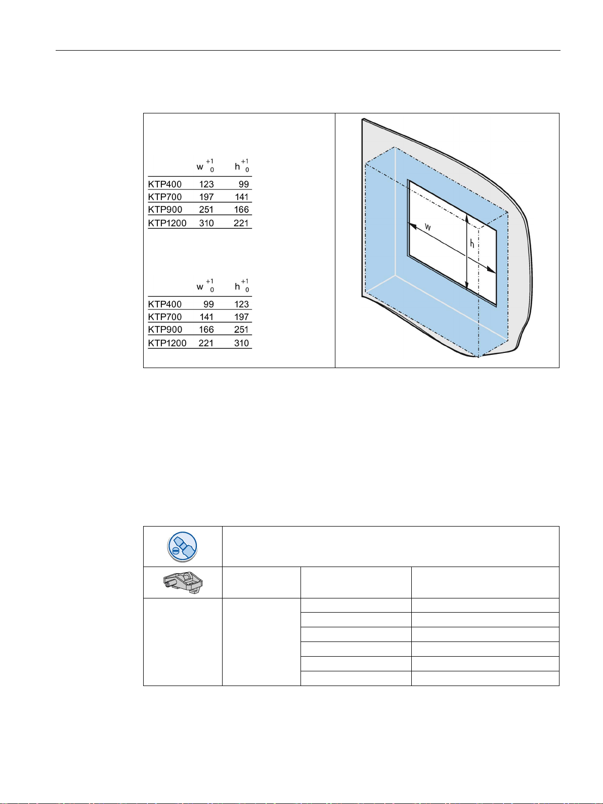
All dimensions in mm
See also
3.2
Mounting the HMI device
Required tools and accessories
KTP400 Basic
4
KTP700 Basic
7
KTP700 Basic DP
7
KTP900 Basic
10
KTP1200 Basic
12
KTP1200 Basic DP
12
3.2 Mounting the HMI device
Dimensions of the mounting cutout for the
Basic HMI devices in horizontal mounting
position:
Dimensions of the mounting cutout for the
Basic HMI devices in vertical mounting
position:
Accessories (Page 15)
Slotted screwdriver, size 2
Mounting clips for HMI device Required quantity
Basic Panels 2nd Generation
Operating Instructions, 10/2016, A5E33293231-AB
25
Page 26

Mounting and connecting
Inserting the HMI device
1.
2.
Securing the HMI device with mounting clips
1.
2.
3.
4.
3.2 Mounting the HMI device
Slide the labeling strip
into the device using
the guide, if available.
Insert the HMI device
into the mounting
cutout from the front.
Make sure that
protruding labeling
strips are not caught
between the mounting
cutout and HMI device.
If mounting clips and grub screws are
available separately in the accessory
kit, insert a grub screw into the
mounting clip bore hole and turn it
several times.
Place the first mounting clip into the
corresponding cutout.
Fasten the mounting clip with a size 2
screwdriver. The maximum permitted
torque is 0.2 Nm.
Repeat steps 1 to 3 for all mounting
clips required to secure your HMI
device.
Basic Panels 2nd Generation
26 Operating Instructions, 10/2016, A5E33293231-AB
Page 27
Mounting and connecting
3.3
Connecting the HMI device
3.3.1
Connection sequence
Required tools and accessories
Procedure
Note
Strain relief
Contacts can be broken or wires
relief.
Provide adequate strain relief for all cables.
See also
3.3 Connecting the HMI device
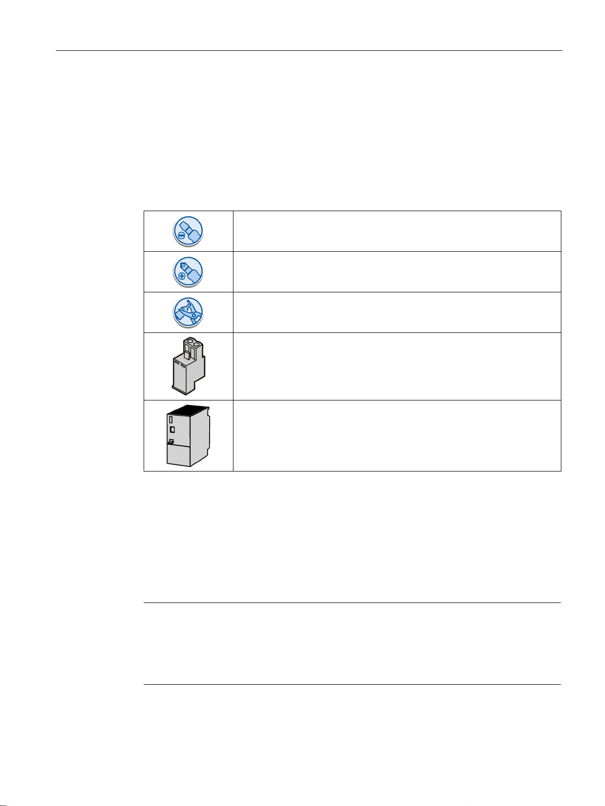
Before you start connecting the HMI device, have the following tools and accessories at
hand:
Slotted screwdriver, size 2
Phillips screwdriver, size 3
Crimp pliers
Power supply connector
24 V DC with sufficient amperage.
See Technical specifications (Page 109)
Keep to the following sequence of tasks when connecting the HMI device:
1. Connecting the equipotential bonding circuit (Page 28)
2. Connecting the power supply (Page 29)
3. Connecting the configuration PC (Page 31)
4. Connecting the controller (Page 33)
Securing the cables (Page 38)
Basic Panels 2nd Generation
Operating Instructions, 10/2016, A5E33293231-AB
can be torn off if cables are not provided adequate strain
27
Page 28

Mounting and connecting
3.3.2
Connecting the equipotential bonding circuit
Differences in electrical potential
General requirements for equipotential bonding
Note
Equipotential bonding conductor
Cable shielding is not suitable for equipotential bonding. Always use the prescribed
equipotential bonding conductors. The cross
must not be less than 16
installing MPI and PROFIBUS DP networks. The interface modules may otherwise be
damaged or destroyed.
3.3 Connecting the HMI device
Differences in electrical potential can develop between spatially separated system
components. Such electrical potential differences can lead to high equalizing currents on the
data cables and therefore to the destruction of their interfaces. Equalizing currents can
develop if the cable shielding is terminated at both ends and grounded to different system
parts.
Differences in potential may develop when a system is connected to different mains
supplies.
Differences in potential must be reduced by means of equipotential bonding conductors to
ensure trouble-free operation of the relevant components of the electronic system. The
following must therefore be observed when installing the equipotential bonding circuit:
● The effectiveness of equipotential bonding increases as the impedance of the
equipotential bonding conductor decreases or as its cross-section increases.
● If two system parts are interconnected by means of shielded data cables and their
shielding is bonded at both ends to the grounding/protective conductor, the impedance of
the additionally installed equipotential bonding conductor must not exceed 10% of the
shielding impedance.
● The cross-section of an equipotential bonding conductor must be capable of handling the
maximum equalizing current. The best practical results for equipotential bonding between
two cabinets have been achieved with a minimum conductor cross-section of 16 mm².
● Use equipotential bonding conductors made of copper or galvanized steel. Establish a
large surface contact between the equipotential bonding conductors and the
grounding/protective conductor and protect them from corrosion.
● Clamp the shielding of the data cable from the HMI device flush at the equipotential rail
using suitable cable clamps. The equipotential rail should be very close to the HMI
device.
● Route the equipotential bonding conductor and data cables in parallel and with minimum
clearance between them.
-section of the equipotential bonding conductor
mm². Always use cables with an adequate cross-section when
Basic Panels 2nd Generation
28 Operating Instructions, 10/2016, A5E33293231-AB
Page 29
Mounting and connecting
Procedure
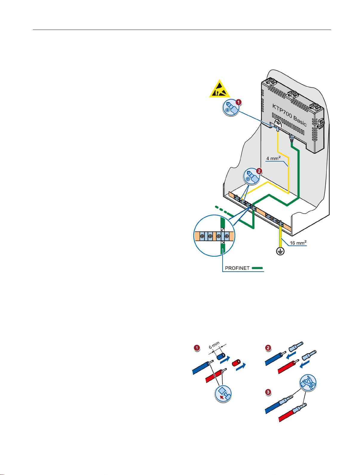
1.
2.
3.3.3
Connecting the power supply
Stripping the cable
Use power supply cables with a
maximum cross
1. Strip the ends of two power supply
2.
3.
3.3 Connecting the HMI device
Interconnect the functional earth
connection of the HMI device with
an equipotential bonding conductor,
cross-section 4 mm
Connect the equipotential bonding
conductor to the equipotential
bonding rail.
2
.
cables to a length of 6 mm.
Attach cable sleeves to the bare
cable ends.
Basic Panels 2nd Generation
Operating Instructions, 10/2016, A5E33293231-AB
Install the end sleeves on the
cable ends using the crimp pliers.
-section of 1.5 mm2.
29
Page 30
Mounting and connecting
Procedure
NOTICE
24 V DC only
NOTICE
Safe electrical isolation
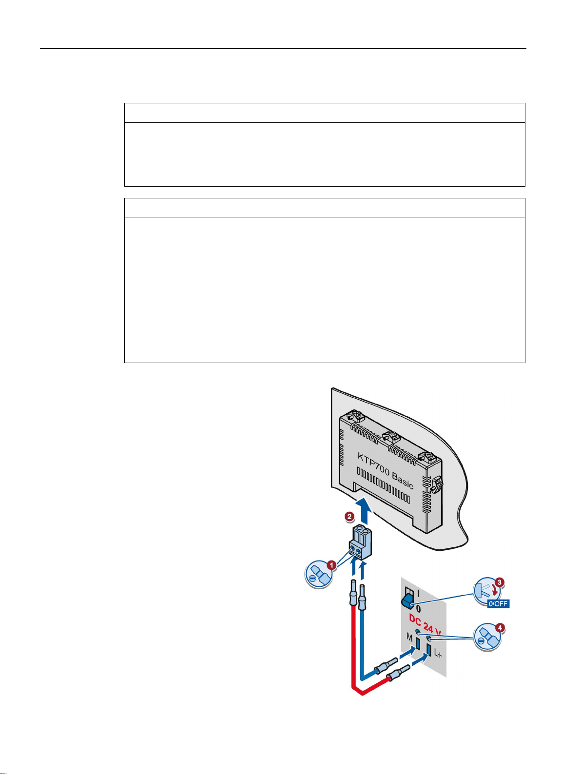
1.
2.
3.
4.
3.3 Connecting the HMI device
An incorrectly dimensioned power supply can destroy the HMI device.
Use a 24 V DC power supply with adequate amperage; see Technical specifications
(Page 109).
For the 24 V DC supply, use only power supply units with safe electrical isolation in
accordance with IEC 60364-4-41 or HD 384.04.41 (VDE 0100, Part 410), e.g. conforming
to the SELV/PELV standard.
The supply voltage must be within the specified voltage range. Otherwise, malfunctions at
the HMI device cannot be ruled out.
Applies to non-isolated system configurations:
Connect the GND 24 V connection from the 24 V power supply output to equipotential
bonding for uniform reference potential. You should always select a central point of
termination.
Connect the two power supply
cables to the power supply
connector as shown. Secure the
power supply cables with a slotted
screwdriver.
Connect the power supply
connector to the HMI device.
Check the correct polarity of the
cables using the interface marking
on the back of the HMI device.
Switch off the power supply.
Insert the two remaining cable
ends into the power supply
terminals and secure them with
the slotted screwdriver.
Ensure correct polarity.
Basic Panels 2nd Generation
30 Operating Instructions, 10/2016, A5E33293231-AB
Page 31
Mounting and connecting
3.3.4
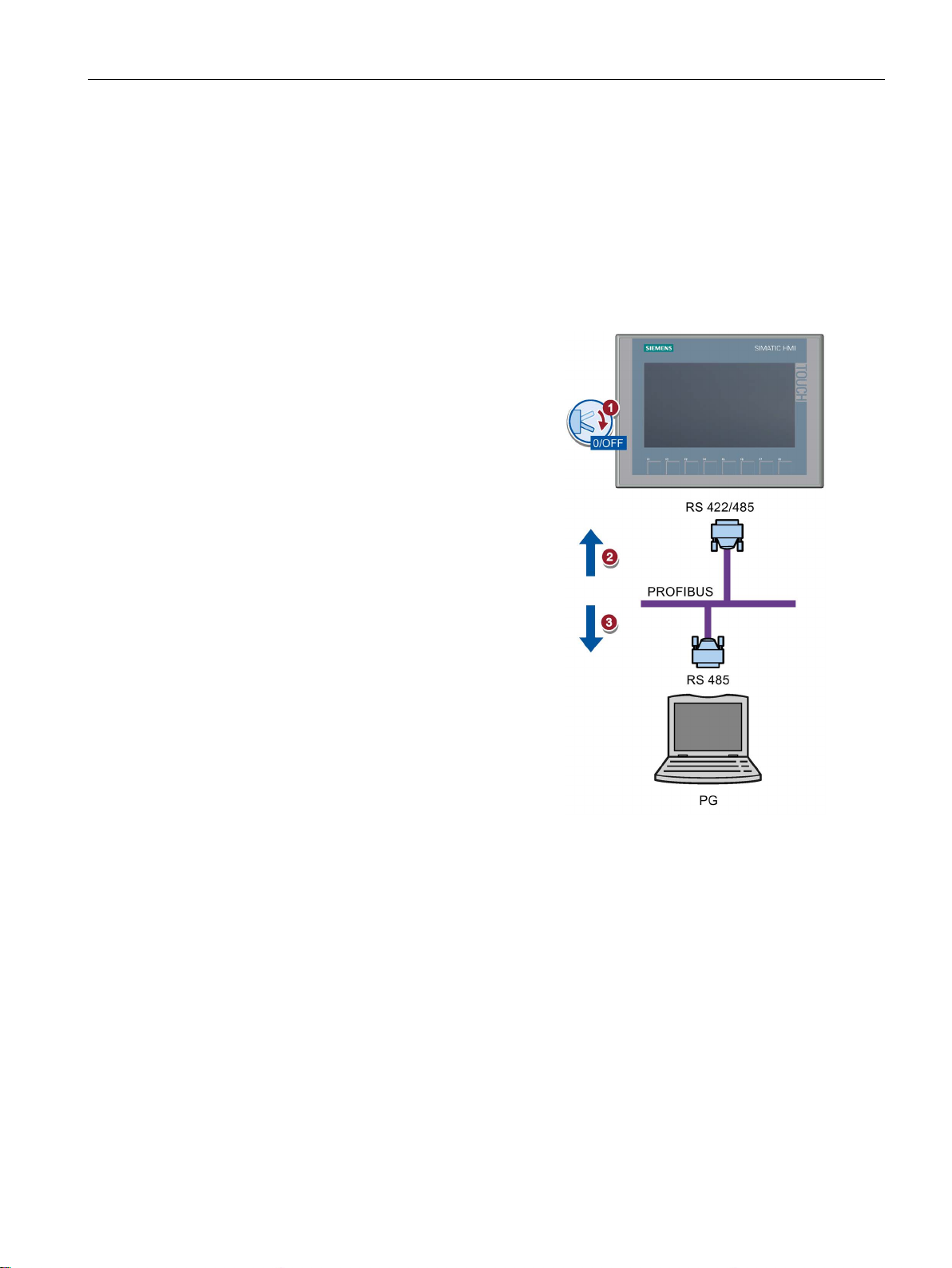
Connecting a programming device
Connecting a programming device to a Basic Panel DP
1.
2.
3.
3.3.5
Connecting the configuration PC
3.3 Connecting the HMI device
A programming device gives you the following options:
● Transfer a project
● Transfer an HIM device image
Shut down the HMI device.
Connect an RS 485 PROFIBUS
connector to the HMI device.
Connect an RS 485 PROFIBUS
connector to the programming
device.
Basic Panels 2nd Generation
Operating Instructions, 10/2016, A5E33293231-AB
A configuration PC gives you the following options:
● Transfer a project
● Transfer an HIM device image
● Reset the HMI device to factory settings
31
Page 32
Mounting and connecting
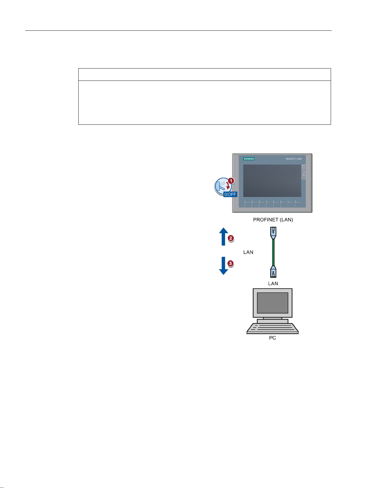
Connecting a configuration PC to a Basic Panel with PROFINET interface
NOTICE
Data network security for communication via Ethernet
1.
2.
3.
See also
3.3 Connecting the HMI device
With Ethernet-based communication via PROFINET, the end user is responsible for the
security of the data network; proper functioning of the data network cannot be guaranteed
under all circumstances, for example, in case of targeted attacks that result in an overload
of the device.
Use a CAT5 Ethernet cable or higher to connect the configuration PC.
Shut down the HMI device.
Connect one RJ45 connector of the
LAN cable to the HMI device.
Connect the other RJ45 connector of
the LAN cable to the configuration PC.
Data transmission options (Page 75)
Accessories (Page 15)
Basic Panels 2nd Generation
32 Operating Instructions, 10/2016, A5E33293231-AB
Page 33
Mounting and connecting
3.3.6
Connecting the controller
Note
Note the following when connecting the controller to a panel:
•
•
•
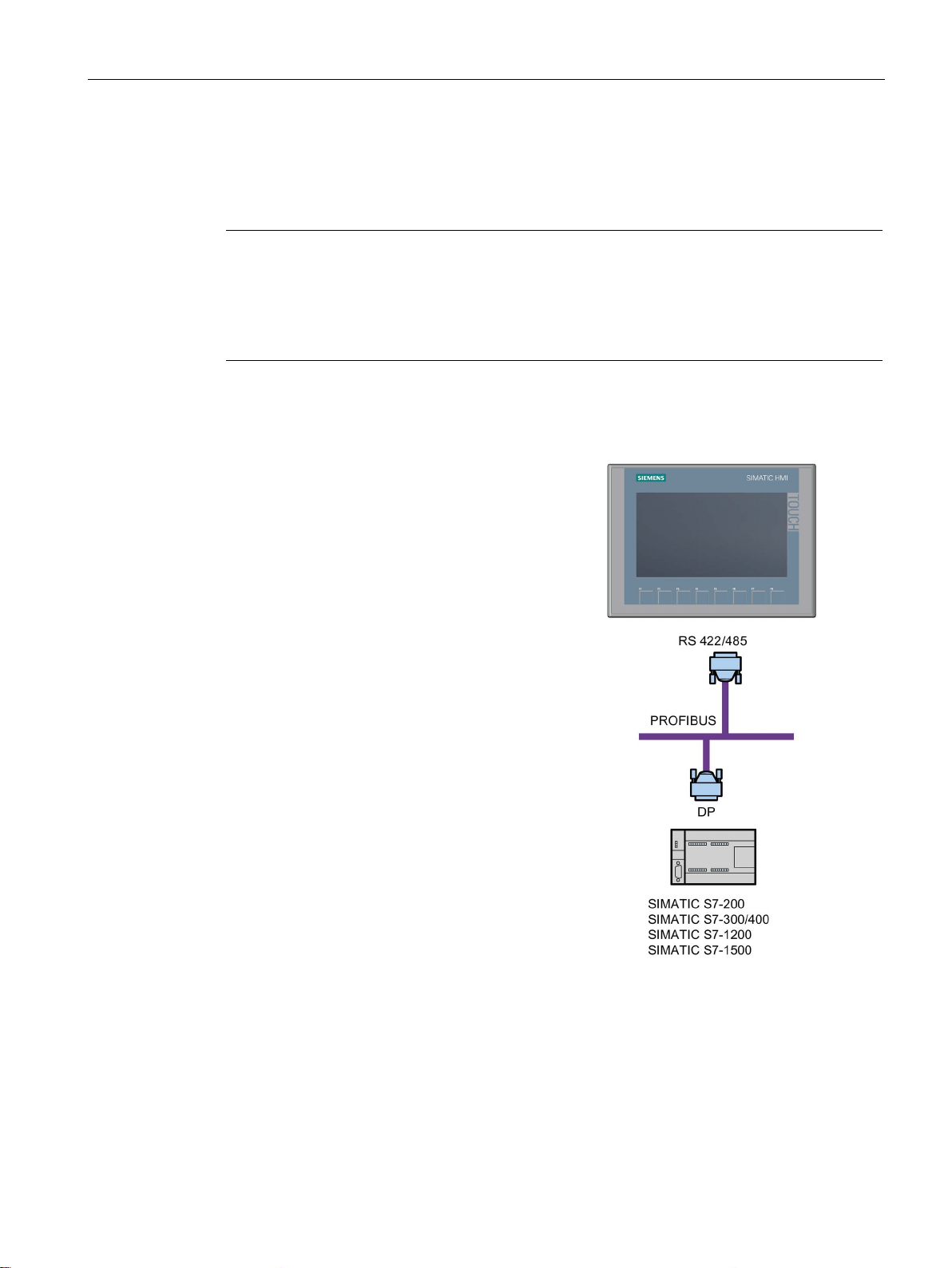
Connecting a controller to a Basic Panel DP
You can connect Basic Panels DP via the
RS
SIMATIC controllers:
•
•
•
•
•
•
You can connect Basic Panels DP to the
following controllers:
•
•
•
•
3.3 Connecting the HMI device
If the HMI device contains an operating system and an executable project, connect the HMI
device to the controller.
Route the data lines parallel to the equipotential bonding conductors
Connect the shields of the data lines to the ground
You can operate a maximum of four controllers at the same time.
422/RS 485 interface to the following
SIMATIC S7-200
SIMATIC S7-300/400
SIMATIC S7-1200
SIMATIC S7-1500
WinAC
SIMOTION
Modicon Modbus RTU
Allen Bradley DF1
Mitsubishi FX
Omron Host Link
Basic Panels 2nd Generation
Operating Instructions, 10/2016, A5E33293231-AB
33
Page 34
Mounting and connecting
Connecting a controller to a Basic Panel with PROFINET interface
NOTICE
Data network security for communication via Ethernet
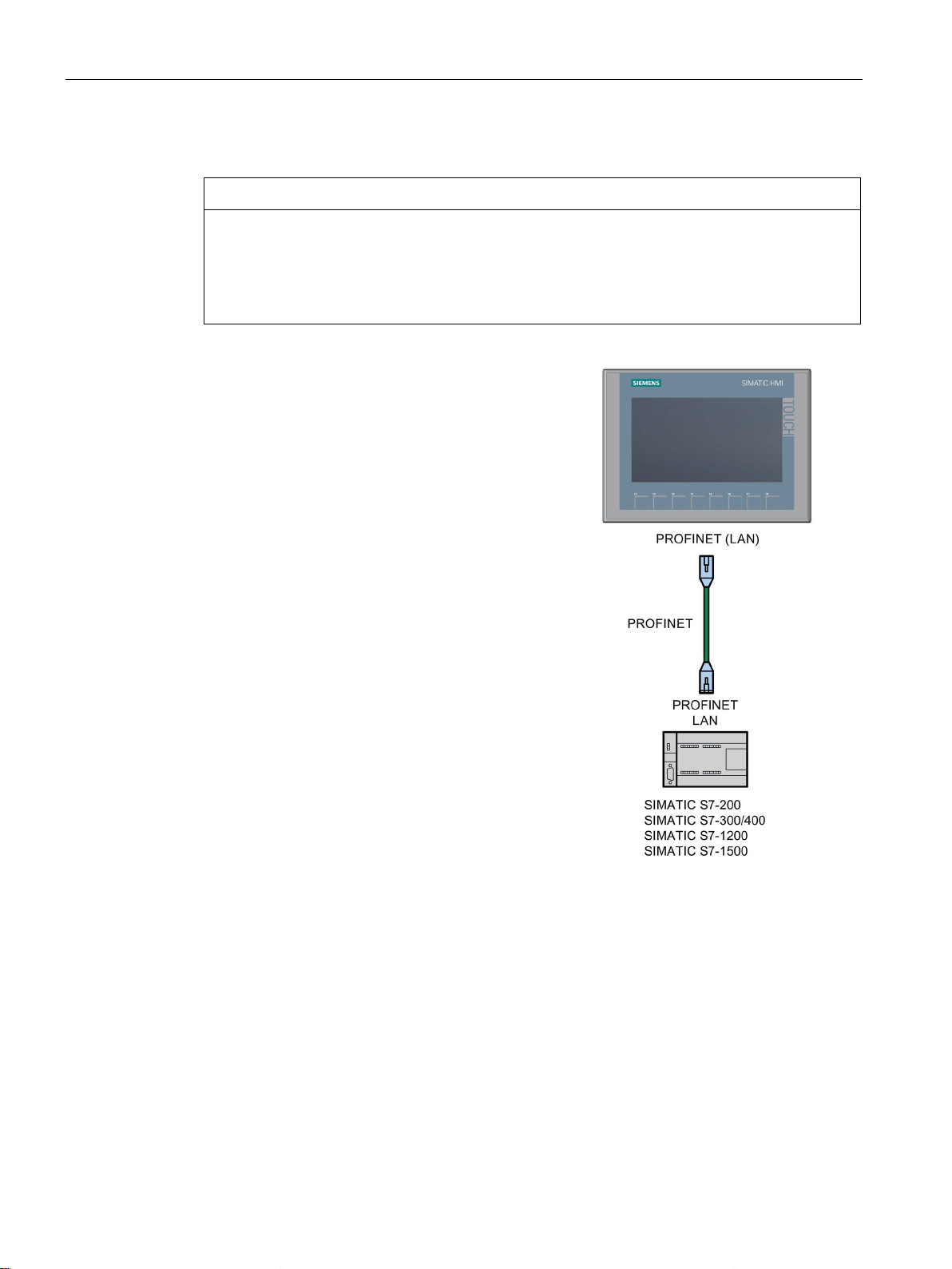
You can connect Basic Panels with P
interface to the following SIMATIC controllers:
•
•
•
•
•
•
•
You can connect Basic Panels with PROFINET
interface to the following controllers:
•
•
•
The connection is set up via PROFINET/LAN.
See also
3.3 Connecting the HMI device
With Ethernet-based communication via PROFINET, the end user is responsible for the
security of the data network; proper functioning of the data network cannot be guaranteed
under all circumstances, for example, in case of targeted attacks that result in an overload
of the device.
ROFINET
SIMATIC S7-200
SIMATIC S7-300/400
SIMATIC S7-1200
SIMATIC S7-1500
WinAC
SIMOTION
LOGO!
Modicon Modbus TCP/IP
Allen Bradley EtherNet/IP
Mitsubishi MC TCP/IP
Accessories (Page 15)
Connecting the equipotential bonding circuit (Page 28)
Basic Panels 2nd Generation
34 Operating Instructions, 10/2016, A5E33293231-AB
Page 35

Mounting and connecting
3.3.7
Connecting a USB device
Note when connecting
Note
Connect a USB mouse or USB keyboard only for commissioning and servicing purposes to
the USB port.
Note
USB 2.0 certified cable required
If you use
Use only USB cables that are labeled "Certified
Note
USB cable length maximum 1.5 m
USB cables with lengths of more than 1.5
The cable may not be longer than 1.5
Note
Functional problem with USB port
If you connect an external device with a 230 V power supply to the USB port without using
an non
Use a non
3.3 Connecting the HMI device
Below are examples of devices designed for industrial use you can connect to the
USB type A interfaces of the HMI device:
● External mouse
● External keyboard
● USB stick
● Industrial USB Hub 4
Additional information is available in the section "Accessories (Page 15)".
a USB cable which is not USB 2.0 certified, errors may occur during data transfer.
HI-SPEED USB 2.0".
m do not ensure secure data transfer.
m.
-insulated installation, you may experience functional problems.
-insulated system design.
Basic Panels 2nd Generation
Operating Instructions, 10/2016, A5E33293231-AB
35
Page 36
Mounting and connecting
Note
Excessive rated load on port
A USB device with too high a power load may possibly cau
Observe the values for the maximum load of the USB interface. You can find the values in
the chapter "
Note
USB stick is not detected.
Depending on the type of USB stick you use, it may happen that the operating system does
not detect the USB stick. In this case, use a different USB stick.
3.4
Switching on and testing the HMI device
Switching on the HMI device
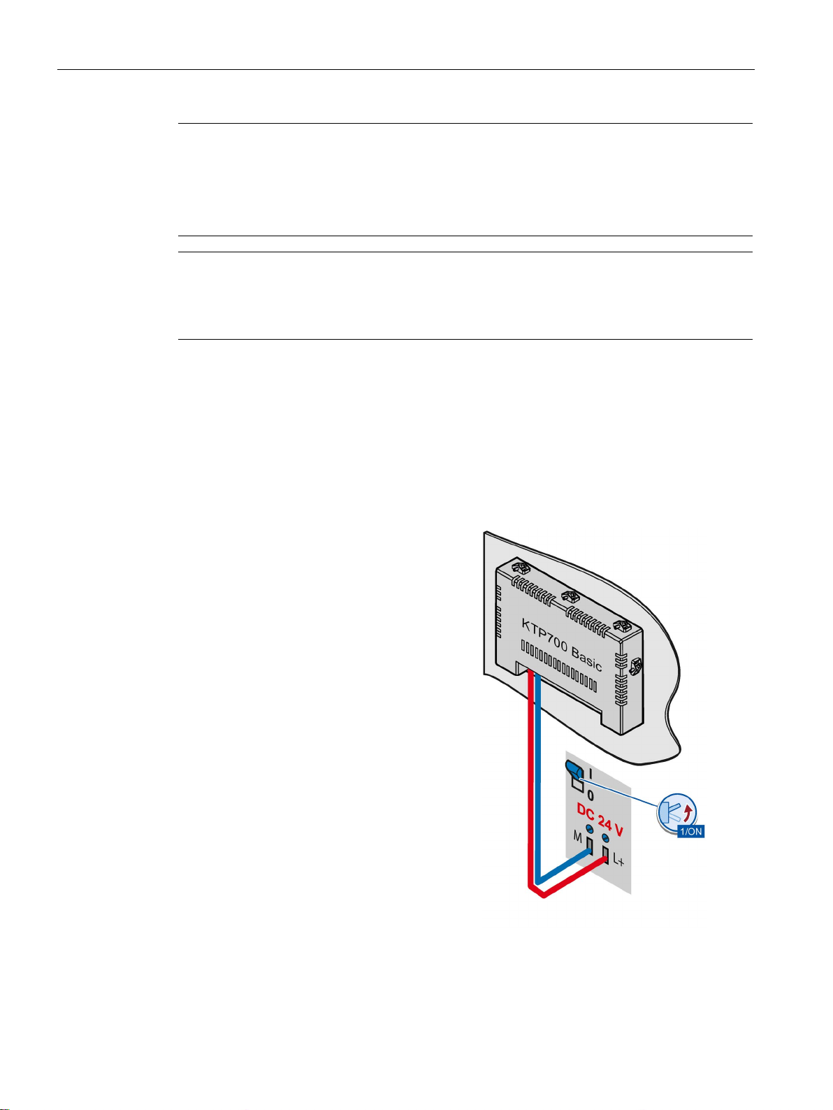
Switching on the power supply.
The screen lights up shortly after power
is switched on.
If the HMI device fails to start, you may
have crossed the cables on the power
supply connector. Check the connected
cables and change their connection.
3.4 Switching on and testing the HMI device
se functional problems.
USB (Page 114)".
Basic Panels 2nd Generation
36 Operating Instructions, 10/2016, A5E33293231-AB
Page 37
Mounting and connecting
• Press the "Transfer" button to set the
•
•
settings.
Switching off the HMI device
3.4 Switching on and testing the HMI device
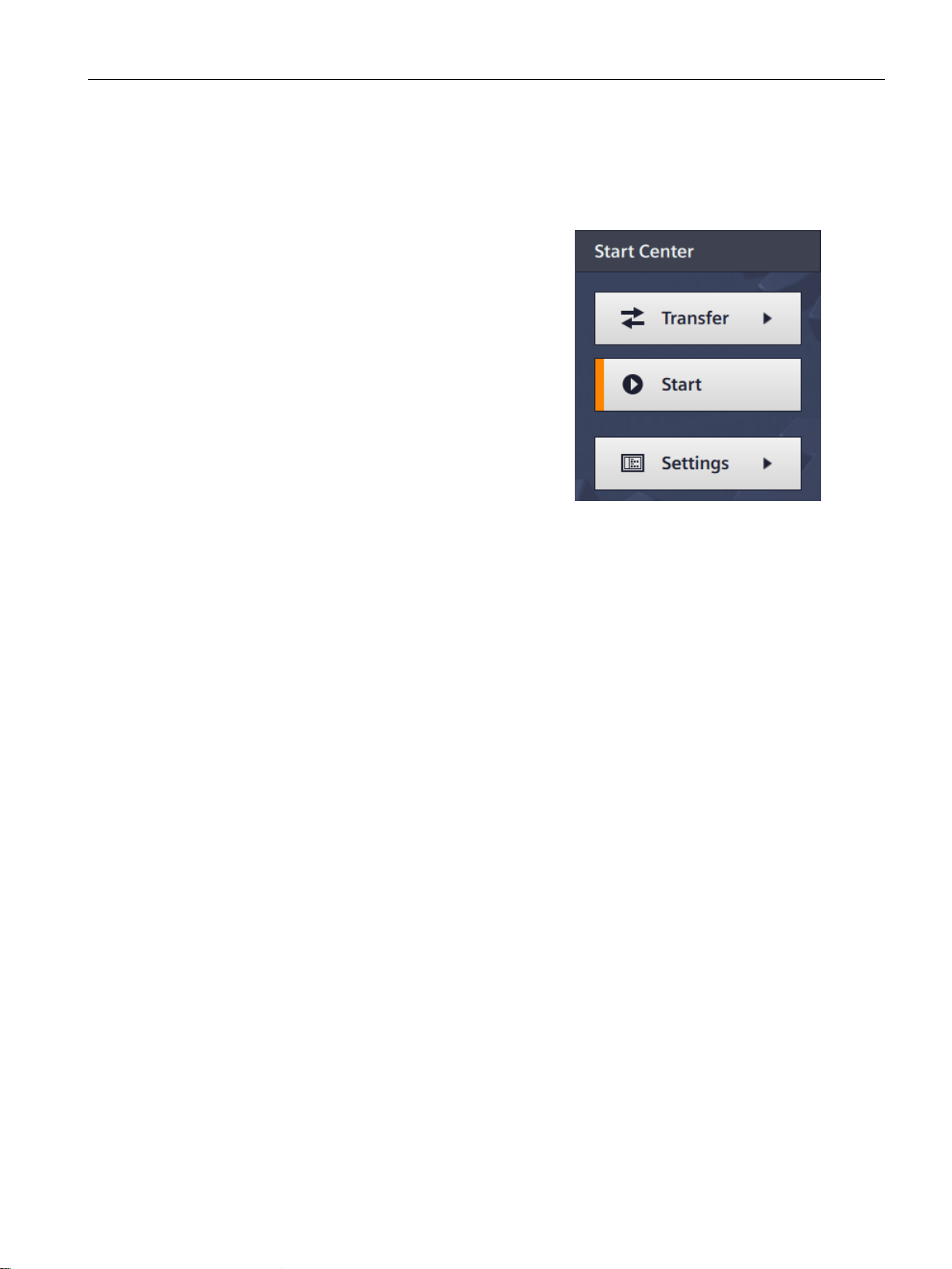
The Start Center opens after the operating system has started.
You operate the Start Center using the buttons on the touch screen or a connected mouse or
keyboard.
HMI device to "Transfer" mode.
The "Transfer" mode can only be
activated when at least one data
channel has been enabled for the
transfer.
Press the "Start" button to start the
project on the HMI device.
Press the "Settings" button to start
the "Settings" page of the Start
Center.
You can change various settings on
this page, for example, the transfer
1. Close any active projects on the HMI device.
2. Switch off the HMI device. You have the following shutdown options:
– Switch off the power supply.
– Unplug the power supply connector from the HMI device.
Basic Panels 2nd Generation
Operating Instructions, 10/2016, A5E33293231-AB
37
Page 38
Mounting and connecting
3.5
Securing the cables
NOTICE
Strain relief
3.5 Securing the cables
Contacts can be broken or wires can be torn off if cables are not provided adequate strain
relief.
Provide adequate strain relief for all cables.
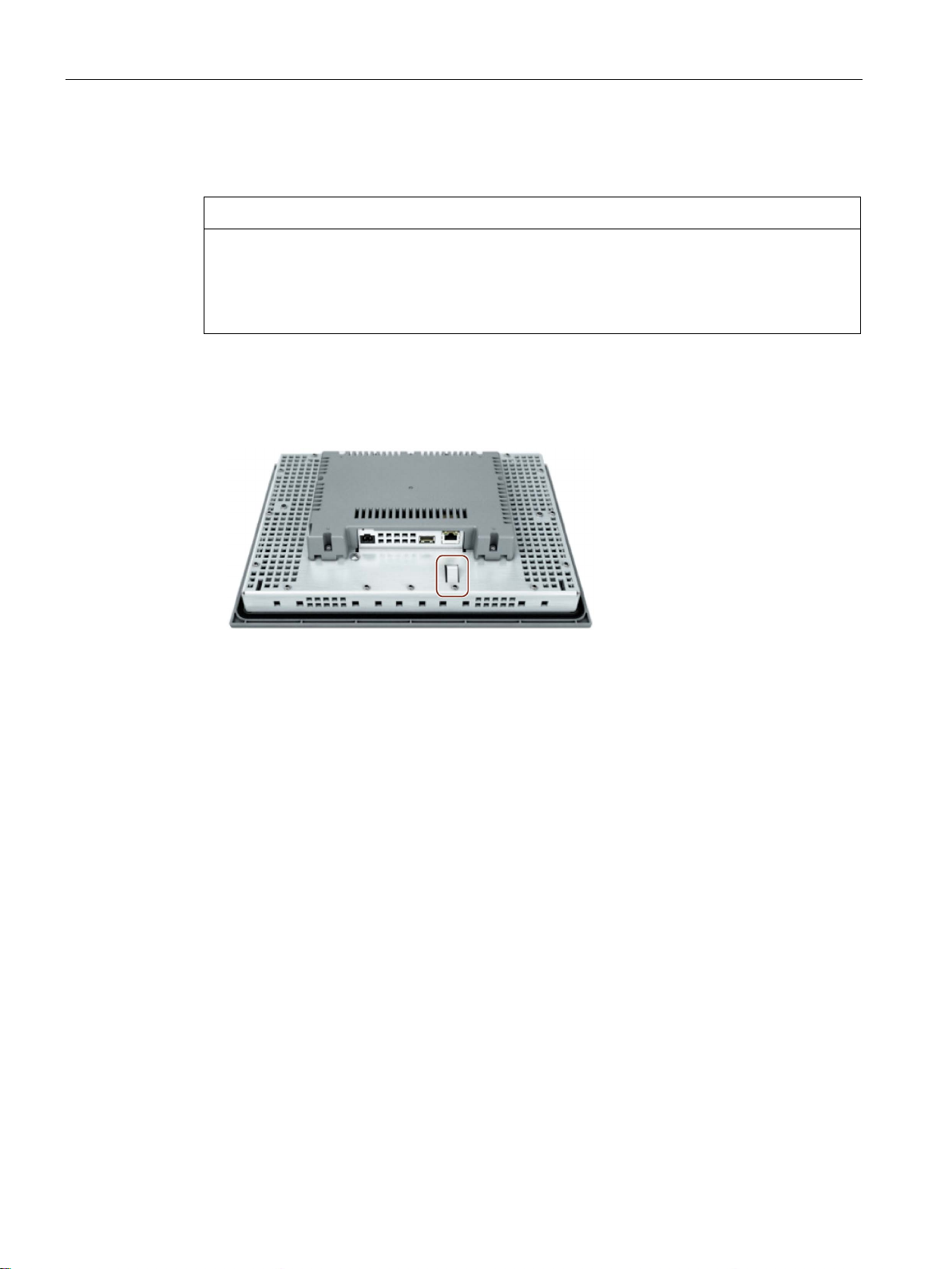
The following HMI devices come equipped with a fixing element on the back for strain relief:
● KTP900 Basic
● KTP1200 Basic
After the power-on test, use a cable tie to secure the connected cables to the marked fixing
element in order to provide strain relief.
Basic Panels 2nd Generation
38 Operating Instructions, 10/2016, A5E33293231-AB
Page 39
4
4.1
Overview
DANGER
Incorrect operation
Operating the touch screen
NOTICE
Damage to the touch screen
Triggering unintended actions
Note
The HMI device returns a visual feedback as soon as it detects that an operating element
has been touched.
The visual feedback is independent of any communication with the c
feedback signal therefore does not indicate whether or not the relevant action is actually
executed.
All Basic Panels 2nd Generation come equipped with a touch screen and function keys. You
use the touch screen to operate the Start Center or the project running on your HMI device.
You use the function keys to trigger the associated configured functions within a project.
A project can contain certain operations that require in-depth knowledge about the specific
system on the part of the operator.
Ensure that only trained professional personnel operate the system.
Pointed or sharp objects, abrupt contact, and continuous gesture operation can significantly
reduce the life of the touch screen and possibly lead to total failure of the touch screen.
• Do not touch the touch screen with pointed or sharp objects.
• Avoid contacting the touch screen abruptly with hard objects.
• Avoid continuous operation of the touch screen with gestures.
Touching several operating elements at the same time can trigger unintended actions.
Touch only one operating element on the screen at a time.
Operating elements are touch-sensitive symbols on the screen of the HMI device.
They are basically operated in the same way as mechanical keys. You activate operating
elements by touching them with your finger.
Basic Panels 2nd Generation
Operating Instructions, 10/2016, A5E33293231-AB
ontroller. The visual
39
Page 40

Operating the device
Buttons
Shading below
Shading on top
Invisible buttons
I/O fields
Note
Description of all operating elements
A comprehensive description of all operating elements for your HMI device is provided in
"Display and operating ele
Operating function keys
Function keys with global function assignment
Function keys with local function assignment
4.1 Overview
Examples:
●
Buttons can assume the following states:
"Untouched"
"Touched"
●
By default, the focus on invisible buttons is not indicated after they are selected. No
optical operation feedback is provided in this case.
The configuration engineer may, however, configure invisible buttons so that their outline
appears as lines when touched. This outline remains visible until you select another
operating element.
●
When you touch an I/O field, the screen keyboard is displayed, e.g. for entry of a
password. The type of keyboard depends on the mounting position and the touched
operating element.
The screen keyboard is automatically hidden again when input is complete.
ments" section of the WinCC Online Help.
The function keys can be assigned global or local functions:
●
A function key with global function assignment always triggers the same action on the
HMI device or in the controller, regardless of the currently displayed screen. An example
of such an action is the activation of a screen, or the closing of an alarm window.
●
A function key with local function assignment is screen-specific and is therefore only
effective within the active screen. The function assigned to such a function key can vary
from screen to screen.
The function key can be assigned only a single function, either global or local, within a
screen. Local function assignments override global function assignments.
Basic Panels 2nd Generation
40 Operating Instructions, 10/2016, A5E33293231-AB
Page 41
Operating the device
4.2
General functions of the screen keyboard
4.2 General functions of the screen keyboard
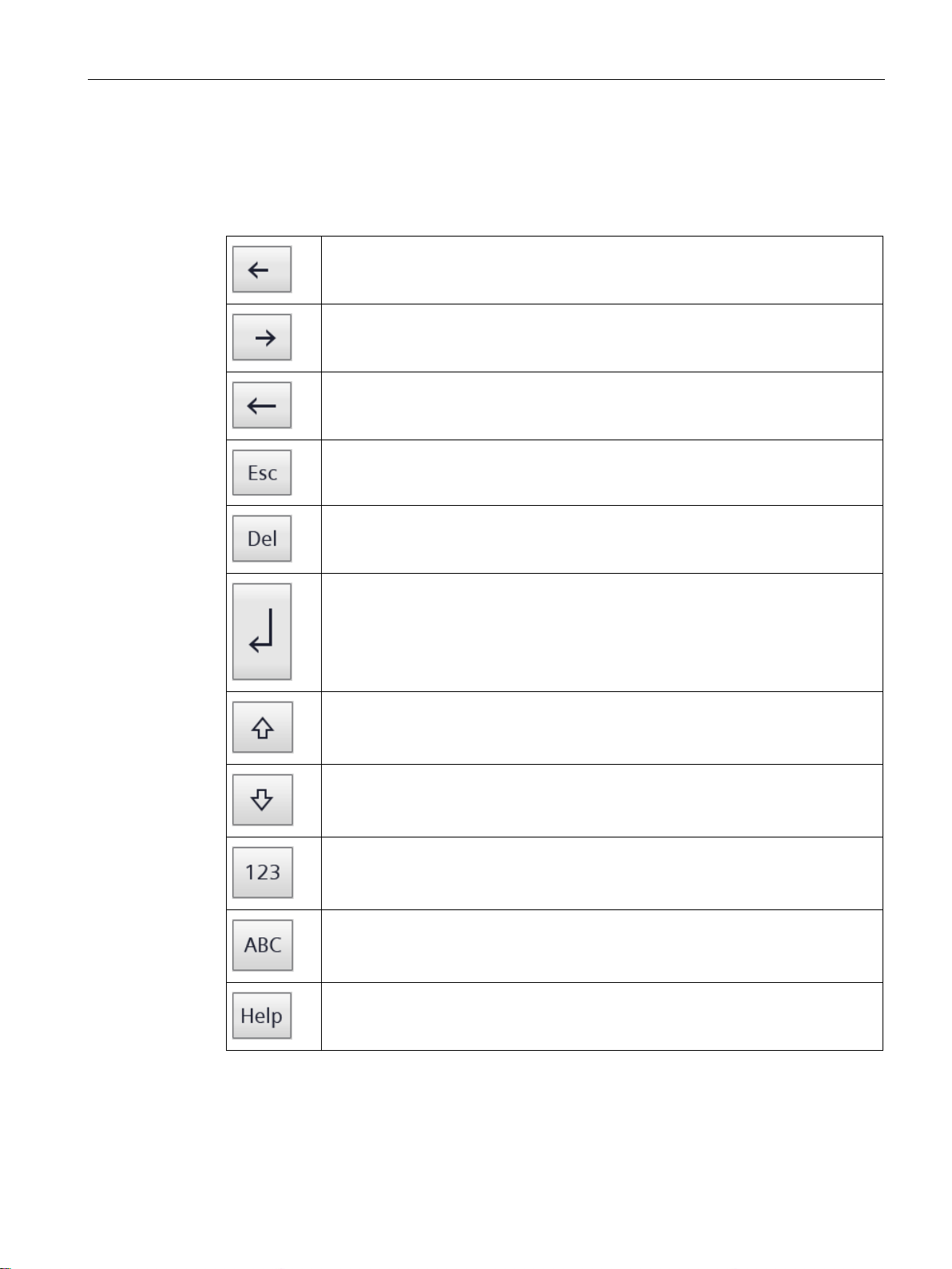
The following keys are available on the screen keyboard of all Basic HMI devices with touch
functionality:
Cursor left
Cursor right
Delete character on left
Cancel input
Delete character on right
Confirm input
Shift to upper case for the next character to be entered
Permanent shift to upper case, corresponds to the "CAPS LOCK" function.
Switchover to numeric keypad
Switchover to alphanumeric keypad
Display infotext
The infotext configured for the operating element is displayed.
Basic Panels 2nd Generation
Operating Instructions, 10/2016, A5E33293231-AB
41
Page 42
Operating the device
4.3
The screen keyboards
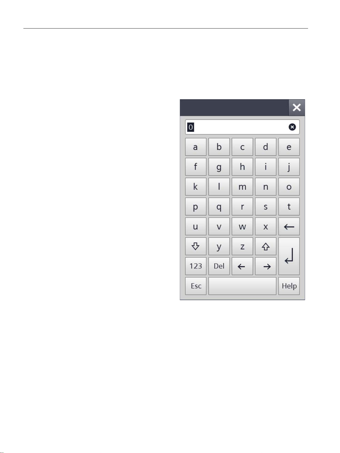
Alphanumerical screen keyboard
4.3 The screen keyboards
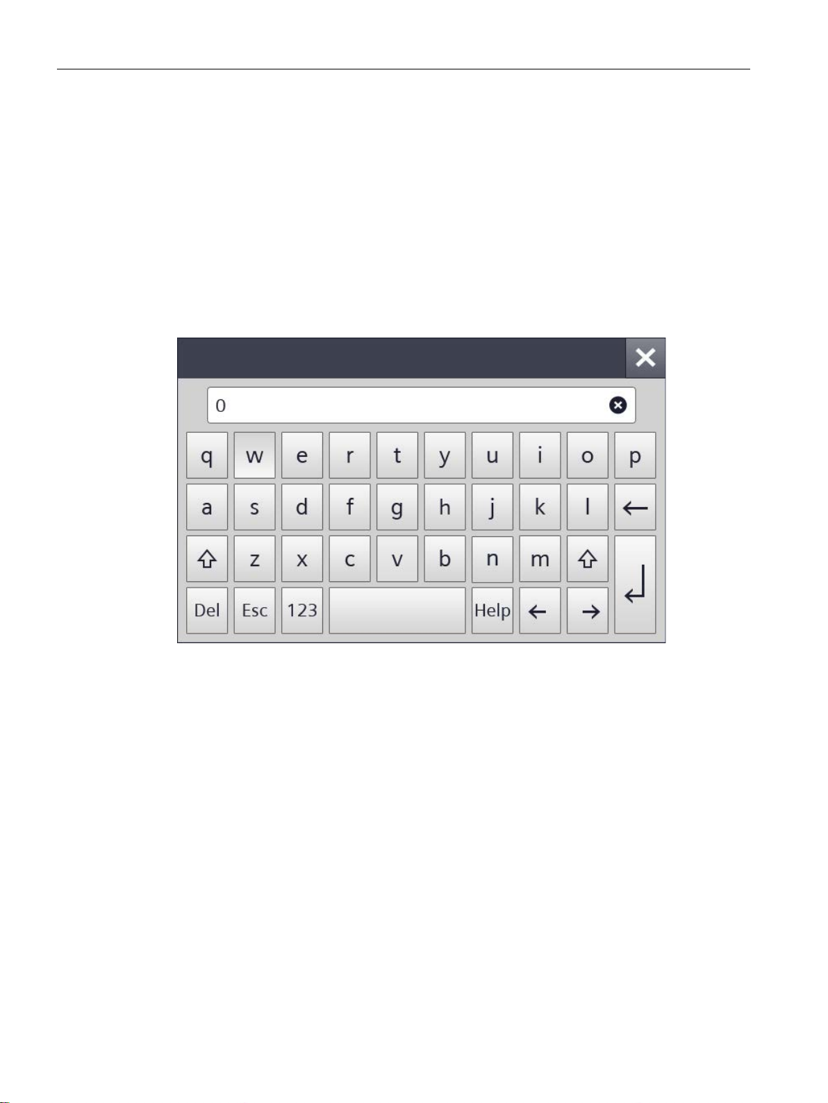
A screen keyboard appears on the HMI device touch screen when you touch an operating
element that requires input. Depending on the type of operating element and the required
input, this may be an alphanumerical or a numerical keyboard.
Both keyboards are available in landscape and in portrait.
For HMI devices in landscape, the alphanumerical keyboard has the assignment of a
computer keyboard in US layout ("QWERTY"). You can set the keyboard to capital letters.
Basic Panels 2nd Generation
42 Operating Instructions, 10/2016, A5E33293231-AB
Page 43
Operating the device
Note
Job mailbox has no effect
Job mailbox 51 "Select screen" has no effect while the screen keyboard is open.
Key assignment
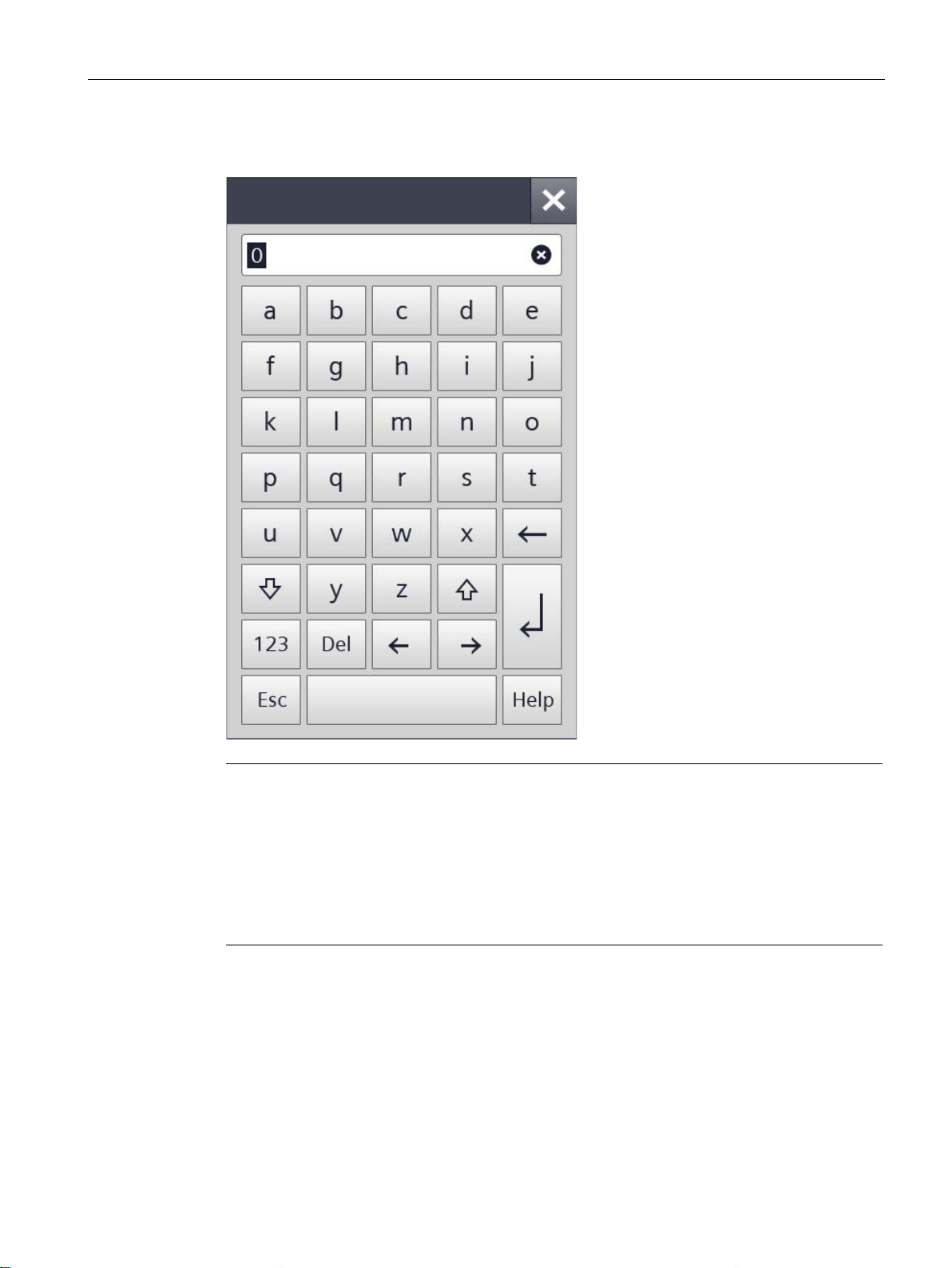
The alphanumerical screen keyboard layout
A language change within the project has no effect on the layout of the alphanumerical
screen keyboard.
4.3 The screen keyboards
For HMI devices in portrait, the letters are sorted alphabetically.
is monolingual.
Basic Panels 2nd Generation
Operating Instructions, 10/2016, A5E33293231-AB
43
Page 44
Operating the device
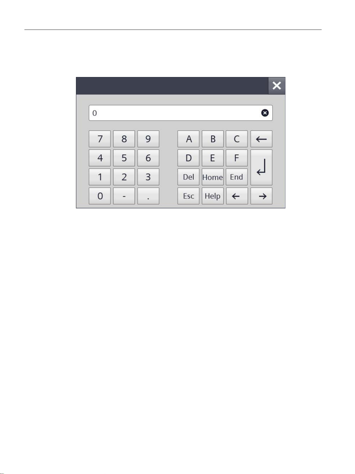
Numerical screen keyboard
4.3 The screen keyboards
The numerical keyboard only offers numbers and the letters A to F for hexadecimal inputs.
Basic Panels 2nd Generation
44 Operating Instructions, 10/2016, A5E33293231-AB
Page 45
Operating the device
Checking numerical value limits
Decimal places of numerical values
4.3 The screen keyboards
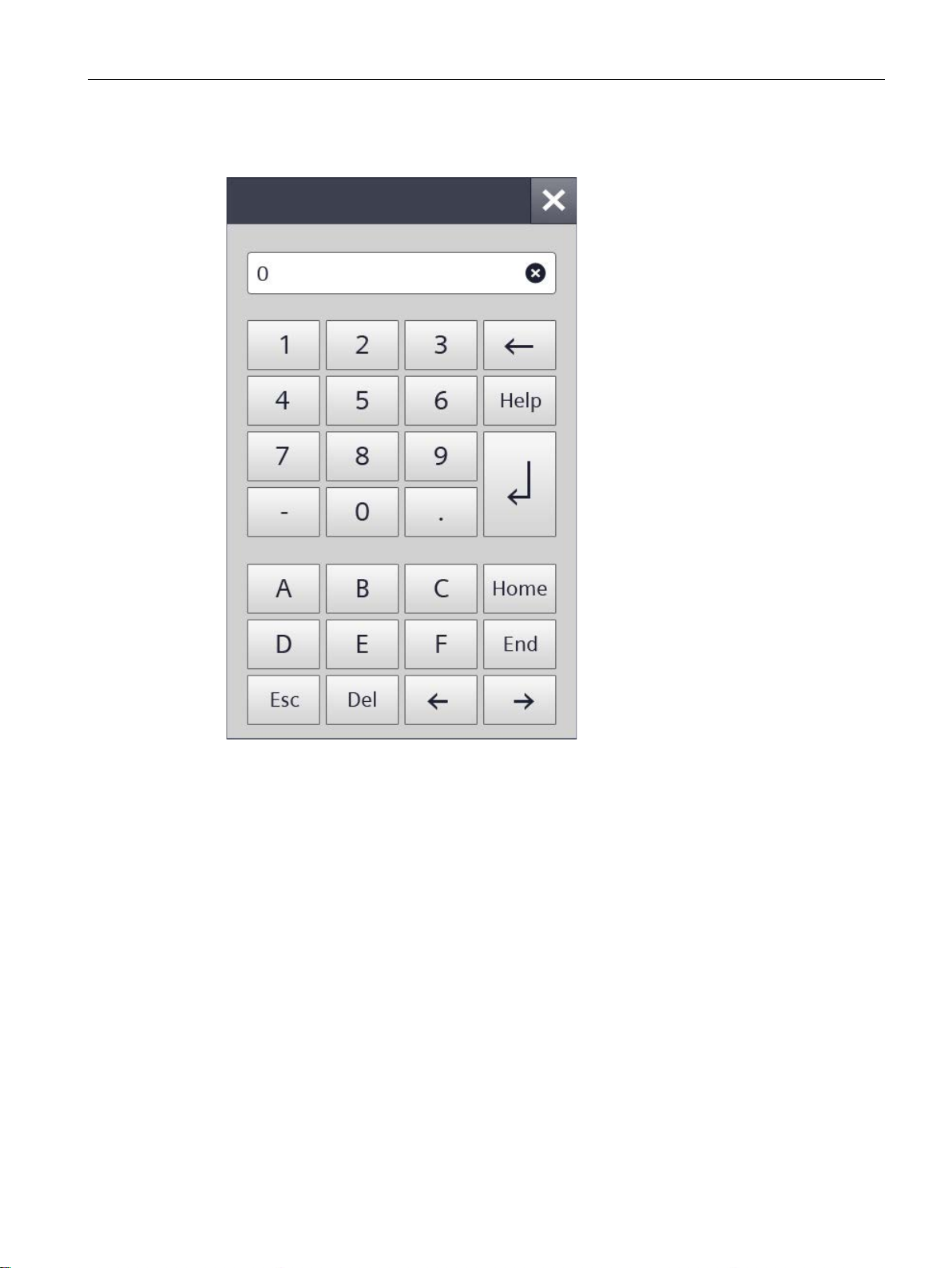
The layout changes accordingly for HMI devices in portrait format.
Tags can be assigned limit values. Any entry of a value outside this limit is rejected. If an
alarm view is configured, a system event is triggered and the original value is displayed
again.
The configuration engineer can define the number of decimal places for a numerical text box.
The number of decimal places is checked when you enter a value in this type of I/O field.
● Decimal places that exceed the limit are ignored.
● Unused decimal places are padded with "0" entries.
Basic Panels 2nd Generation
Operating Instructions, 10/2016, A5E33293231-AB
45
Page 46
Operating the device
4.4
Entering data
Procedure
1.
2.
3.
4.
4.4 Entering data
You make all entries using the screen keyboard.
Touch the desired operating
element on the screen.
The alphanumerical or the
numerical screen keyboard opens.
A value existing in the operating
element is applied to the display
line of the keyboard.
Change or overwrite the value.
Depending on the settings, the
HMI device outputs an audible
signal.
On the alphanumerical keyboard
use the <Shift> key to enter
upper-case letters.
Press <123> on the alphanumerical
screen keyboard to switch to
numbers and special characters.
You return with <ABC>.
Press <Return> key to confirm
your entries, or cancel them with
<ESC>.
Either action closes the screen
keyboard.
Basic Panels 2nd Generation
46 Operating Instructions, 10/2016, A5E33293231-AB
Page 47
5
5.1
Opening the settings
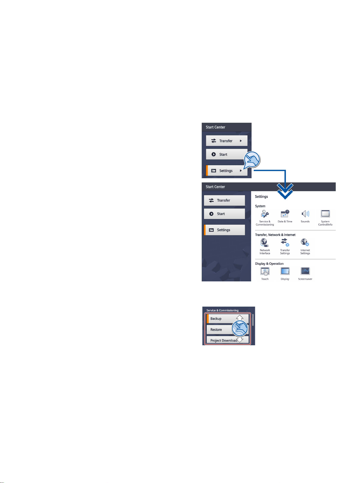
The Start Center opens after the
HMI device has been switched on.
Use the "Settings" button to open the
settings for pa
the device.
You can make the following settings:
•
•
•
•
•
•
The Start Center is divided into a
navigation area and a work area.
I
landscape, the navigation area is on
the left and the work area on the right
in the display.
If the device is configured in portrait,
the navigation area is on the top and
the work area on the bottom in the
display.
When
navigation area or work area is not
sufficient to display all buttons or
icons, scroll bars will be displayed.
You can scroll on the navigation area
or work area using a swipe gesture;
see example on the right.
Scroll within t
area and not on the scroll
bar.
rameter assignment of
Settings for operation
Communication settings
Password protection
Transfer settings
Screen saver
Acoustic signals
f the device is configured in
Basic Panels 2nd Generation
Operating Instructions, 10/2016, A5E33293231-AB
In most entry fields, the entered value is checked, and, if invalid, it is outlined in red and the
value itself is red. The settings are applied and saved when you change to another tab or
window. Invalid input values are not applied.
the display space in the
he outlined
47
Page 48

Configuring the device
Note
Start Center of the 4" device
The buttons "Transfer", "Start" and "Settings" are displayed in a space
Start Center of the 4" device. The following but
navigation area is located between the navigation area and work area:
Protecting the Start Center with a password
Note
If the password is no longer available for the Start Center, you first have to update the
operating system before you can make any changes in the Start Center.
All data on the HMI device is overwritten when you
5.1 Opening the settings
Some settings involve multiple windows similar to a wizard. In this case, the text "Step x/y" is
displayed at the bottom in the center of the work area. With the ">" key at the bottom right,
you advance to the next input window. With the "<" key at the bottom left, you return to the
previous input window.
-saving manner in the
ton for minimizing and maximizing the
You can protect the Start Center against unauthorized operation. You can read the settings
in the Start Center without having entered a password, however, you are not permitted to
edit the settings.
This prevents inadvertent operations and increases security for the system or machine
because the settings cannot be edited.
update the operating system.
Basic Panels 2nd Generation
48 Operating Instructions, 10/2016, A5E33293231-AB
Page 49
Configuring the device
5.2
Overview of functions
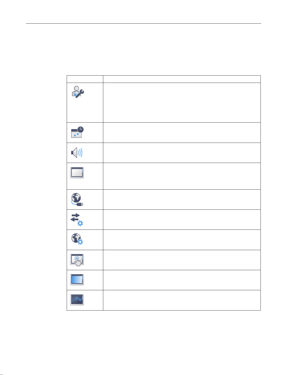
Icon
Function
Editing communication connections (Page 55)
Displaying information about the HMI device (Page 62)
1
2
Available for devices with PROFINET interface
5.2 Overview of functions
The following table shows the functions available in the Start Center for configuring your HMI
device. Individual functions may be hidden, depending on the device type and device
configuration.
Save to external storage medium – Backup (Page 50)
Restore from external storage medium – Restore (Page 51)
1
Load project from external storage medium (Page 52)
Update operating system from external storage medium (Page 53)
Changing the IP address and device name of a controller (Page 54)
Configuring the time server (Page 56)
Enter time and date (Page 57)
Activating the acoustic signal (Page 58)
Configuring Autostart or wait time (Page 59)
Changing the password settings (Page 60)
Displaying licensing information for the HMI device (Page 61)
Change network settings of PROFINET devices (Page 63)
Change network settings of PROFIBUS devices (Page 64)
Assigning transfer parameters (Page 65)
Configure Sm@rt Server (Page 66)
Importing a certificate via USB (Page 67)
Displaying and deleting certificates (Page 68)
Calibrating the touch screen (Page 69)
Changing the monitor settings (Page 70)
Setting the screen saver (Page 71)
1 2
1 2
1 2
Available in connection with an HMI device image that is compatible with WinCC (TIA Portal) V14
or higher.
Basic Panels 2nd Generation
Operating Instructions, 10/2016, A5E33293231-AB
49
Page 50
5.3
Save to external storage medium – Backup
1.
2.
3.
4.
5.
6.
The backup starts and the Transfer screen
is displayed.
Configuring the device
5.3 Save to external storage medium – Backup
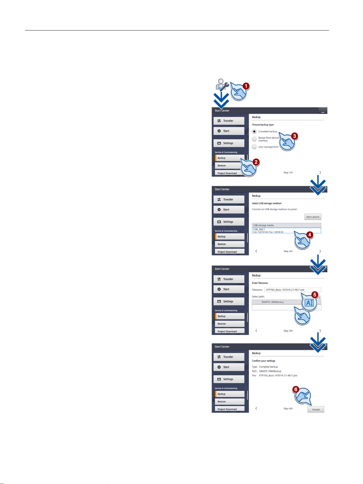
Touch the "Service & Commissioning" icon.
Press the "Backup" button.
With "Backup", you back up the data to
a formatted USB storage medium.
Select the scope of the backup:
– "Complete backup": Complete backup
– "Recipe from device memory":
Recipes only
– "User management":
User management data only
Select the storage medium on which
the data is backed up.
Specify the file name of the backup file
and the path.
If no storage medium is inserted into
the HMI device, the File name and Path
fields are empty.
If not enough memory space is available
on the storage medium, an error message
appears.
Use the "Accept" button to confirm.
Basic Panels 2nd Generation
50 Operating Instructions, 10/2016, A5E33293231-AB
Page 51
5.4
Restore from external storage medium – Restore
NOTICE
Data loss
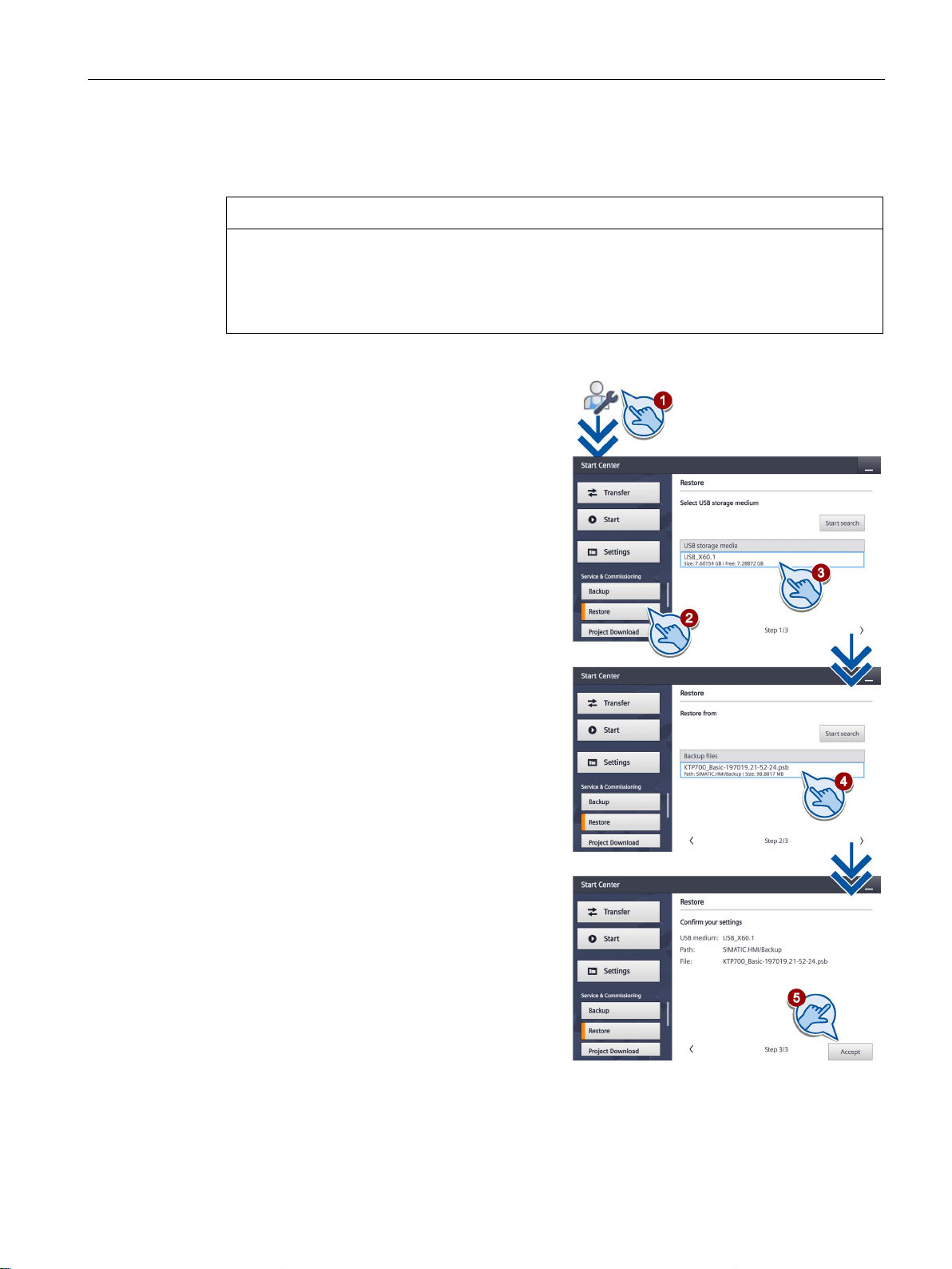
1.
2.
3.
4.
5.
The restore operation starts and the
Transfer screen is displayed.
Configuring the device
5.4 Restore from external storage medium – Restore
All data on the HMI device, including the project and HMI device password, is deleted
during a restore operation. License keys are only deleted after a security prompt.
Back up your data before the restore operation, if necessary.
Touch the "Service & Commissioning"
icon.
Press the "Restore" button.
With "Restore", you restore data that
was backed up to an external USB
storage medium on the HMI device.
Select the storage medium on which
the data is backed up.
Select the backup file. The path is
displayed.
If no storage medium is inserted into
the HMI device, the File name and
Path fields are empty.
Use the "Accept" button to confirm.
Basic Panels 2nd Generation
Operating Instructions, 10/2016, A5E33293231-AB
51
Page 52
Configuring the device
5.5
Load project from external storage medium
NOTICE
Data loss
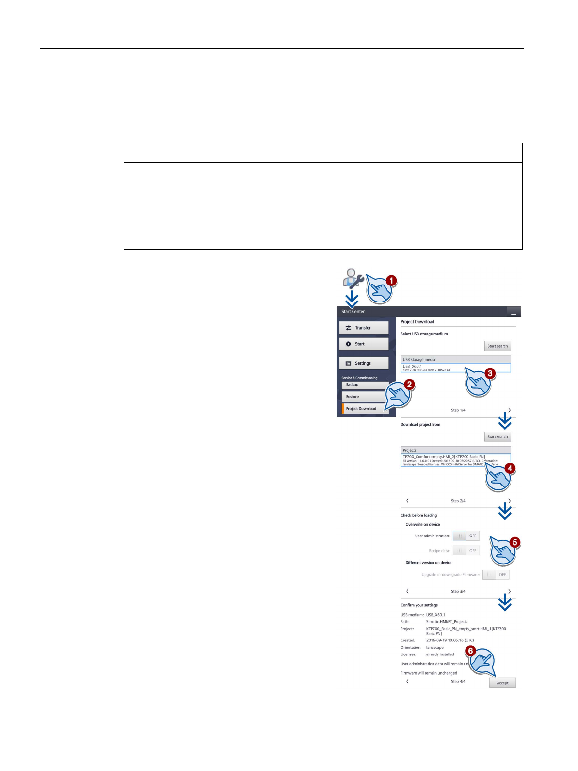
1. Touch the "Service & Commissioning" icon.
2.
3.
4.
5.
6.
The project is loaded into the HMI device.
5.5 Load project from external storage medium
This function is available in connection with an HMI device image that is compatible with
WinCC (TIA Portal) V14 or higher.
When you load a project with the "Upgrade or downgrade Firmware" option, the operating
system of the HMI device is updated. All data on the HMI device, including the HMI device
password, is deleted in the process. Settings in the Start Center are retained. License keys
are backed up to the external storage medium before the operating system update.
Back up your data before the load operation, if necessary.
Press the "Project Download" button.
With "Project Download", you have the
option of loading an individual project
from an external storage medium into the
HMI device.
Select the storage medium on which the
data is backed up.
Select the project file.
If no storage medium is inserted into the
HMI device, the "Projects" list is empty.
Select the options for the project download:
– "User administration:"
Overwrite the user administration on the
HMI device with the user administration
of the project
– "Recipe data:"
Overwrite recipes of the HMI device with
the recipes of the project
– "Upgrade or downgrade Firmware:"
Update firmware on the HMI device if
the firmware version of the HMI device is
incompatible with the firmware version of
the project
Use the "Accept" button to confirm.
Basic Panels 2nd Generation
52 Operating Instructions, 10/2016, A5E33293231-AB
Page 53
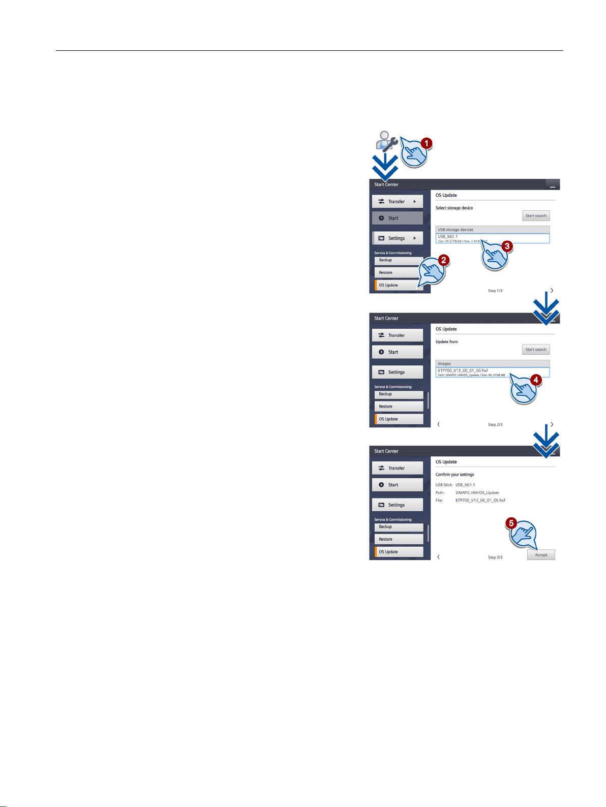
Configuring the device
5.6
Update operating system from external storage medium
1.
2.
3.
4.
5.
The operating system is updated and the
Transfer screen is displayed.
5.6 Update operating system from external storage medium
Touch the "Service & Commissioning"
icon.
Press the "OS Update" button.
With "OS Update", you update the
operating system of the HMI device that
is present as an image on an external
storage medium.
Select the storage medium on which the
image is stored.
Select the image file. The path is
displayed.
If no storage medium is inserted into the
HMI device, the File name and Path
fields are empty.
Use the "Accept" button to confirm.
Basic Panels 2nd Generation
Operating Instructions, 10/2016, A5E33293231-AB
53
Page 54
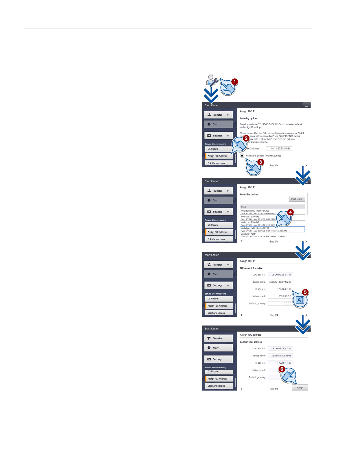
5.7
Changing the IP address and device name of a controller
1.
2.
3.
4.
5.
6.
The displayed IP address and device name
are assigned to the controller.
Configuring the device
5.7 Changing the IP address and device name of a controller
Touch the "Service & Commissioning" icon.
Press the "Assign PLC Address" button.
With "Assign PLC Address" you can
assign configuration-independent
IP addresses and device names to
controllers that are connected to the
HMI device.
The address assignment is available
only for controllers of type S7-1200 (> V2.0)
and S7-1500.
The "IP address is set directly at the device"
option must be enabled in the configuration
of the controller.
Specify the MAC address of a controller
or select automatic search:
– "MAC Address": Indicate a specific
controller
– "Accessible devices in target subnet":
Find all accessible controllers in the
subnet of the
HMI device
If you have selected automatic search,
all controllers that were found are
displayed in a list in the next window.
Select a controller from the list.
Change the IP address and device
name of the selected controller.
Use the "Accept" button to confirm.
Basic Panels 2nd Generation
54 Operating Instructions, 10/2016, A5E33293231-AB
Page 55
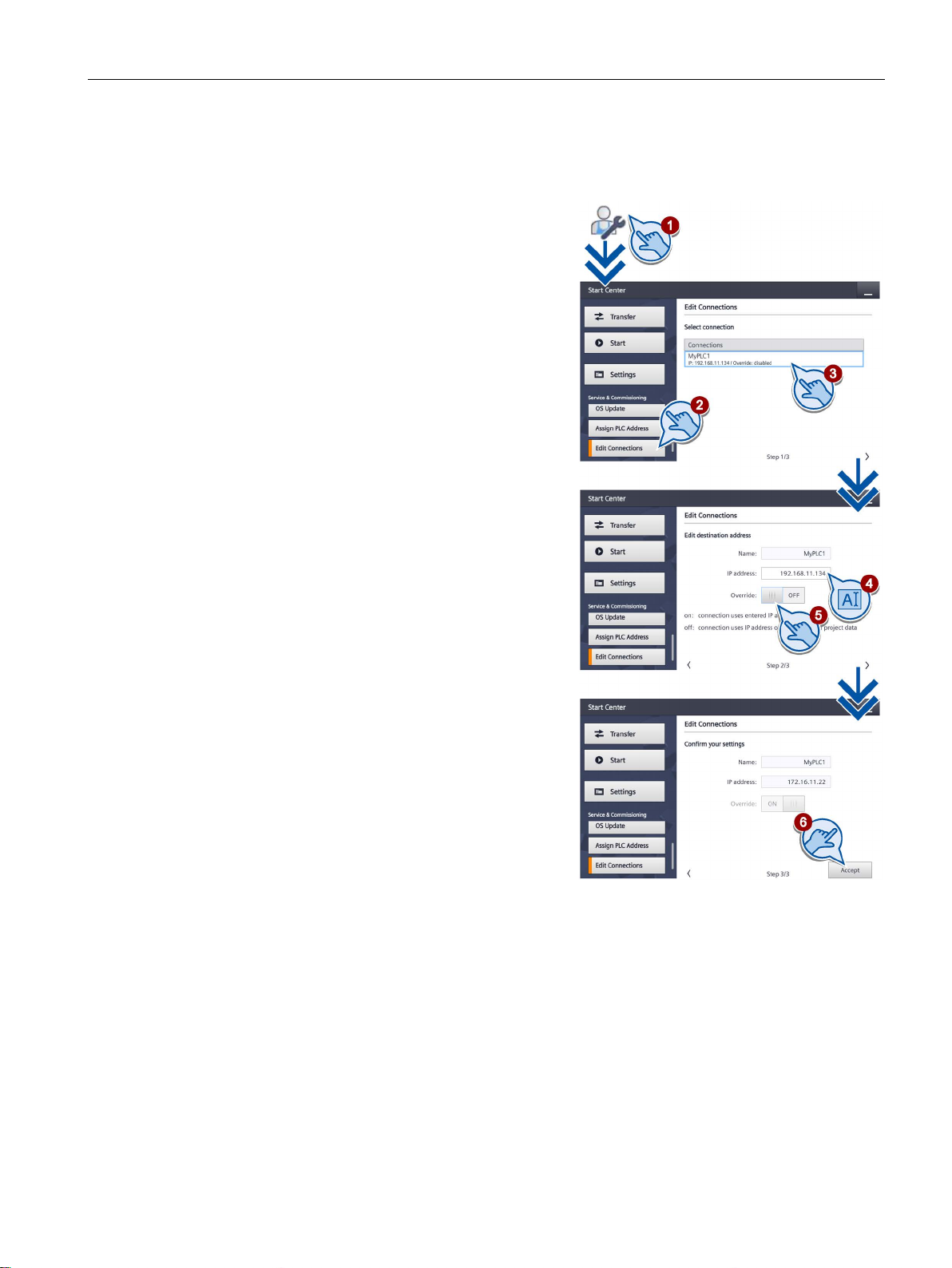
Configuring the device
5.8
Editing communication connections
1.
2.
3.
4.
5.
6.
The configured IP address is overwritten.
5.8 Editing communication connections
Touch the "Service & Commissioning"
icon.
Press the "Edit Connections" button.
With "Edit Connections", you overwrite
the parameters of configured controller
connections
in the current project.
A list shows all communication
connections to controllers.
Select a communication connection
from the list.
The configured name and IP address
are displayed.
You can enter a new IP address.
Set the "Override" switch to "ON".
The connection parameters will only be
overwritten if "Override" is enabled
Use the "Accept" button to confirm.
Basic Panels 2nd Generation
Operating Instructions, 10/2016, A5E33293231-AB
55
Page 56
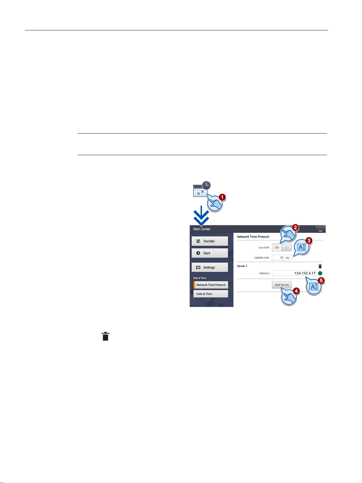
Configuring the device
5.9
Configuring the time server
Note
A time shift is configured in another window; see se
1.
2.
3.
4.
5.
symbol.
5.9 Configuring the time server
The HMI device has a buffered realtime clock. The realtime clock is set by using the
configuration or by using a time server.
To obtain the time of the HMI device from a time server (only for PROFINET devices), you
can specify up to four different time servers. The time-of-day is synchronized via the
"Network Time Protocol" (NTP). The availability of the time server is displayed.
Also specify the update cycle of the time-of-day and, if necessary, a time shift. Update cycle
and time shift are valid for all configured time servers.
ction "Enter time and date (Page 57)".
Touch the "Date & Time" icon.
Set the "Use NTP" switch to "ON"
in order to enable time-of-day
synchronization.
Under "Update Rate", specify the
time interval at which the time of
day will be synchronized.
Value range: 10 ... 86400 sec.
(1 day)
Add a time server using the
"Add Server" button.
Enter the IP address of the time
server under "Address".
The connection to the server is
established.
You can detect the availability of
the server by the green or red
With the button, you remove the corresponding time server from the configuration.
Basic Panels 2nd Generation
56 Operating Instructions, 10/2016, A5E33293231-AB
Page 57
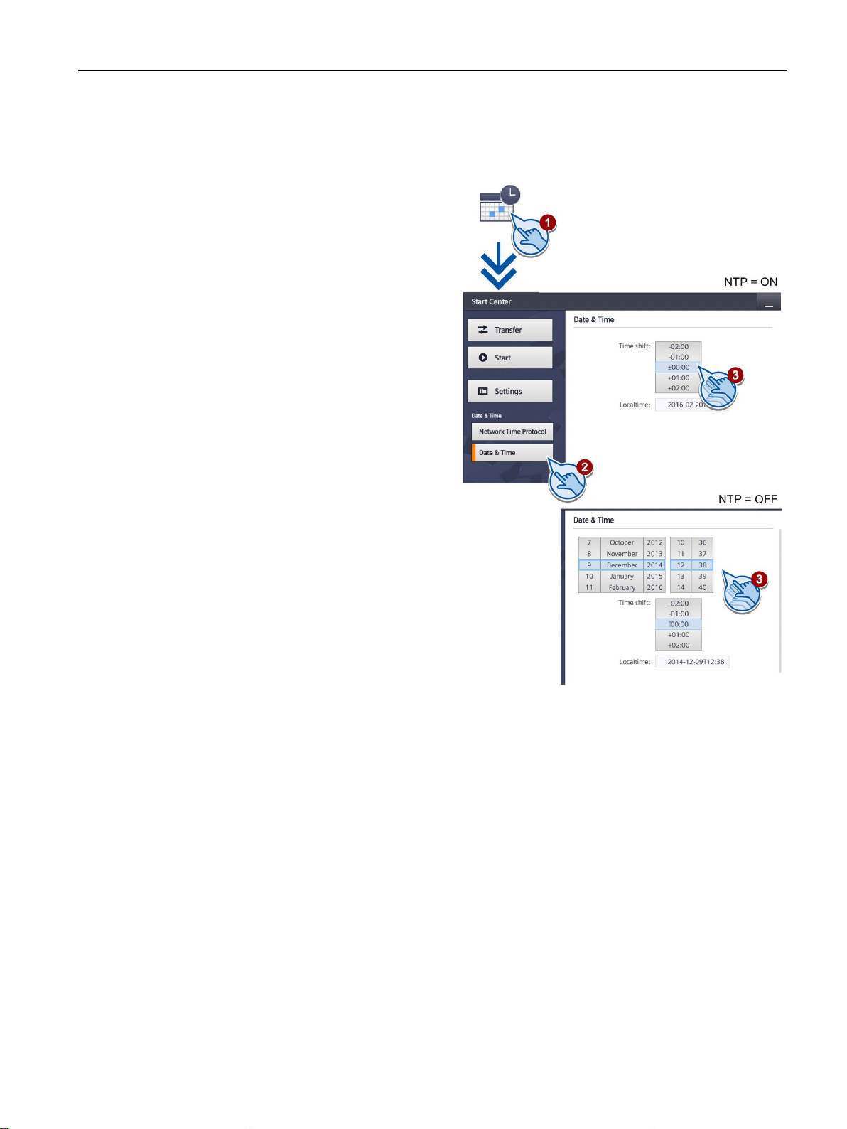
Configuring the device
5.10
Enter time and date
1.
2.
3.
5.10 Enter time and date
Touch the "Date & Time" icon.
Press the "Date & Time" button.
If you are using a time server
(NTP=ON), set a time shift with
the selection wheel under
"Time shift", if required.
If you are not using a time server
(NTP=OFF), set the desired time
and the desired time shift with the
selection wheel.
The resulting local time is
displayed under "Localtime".
Basic Panels 2nd Generation
Operating Instructions, 10/2016, A5E33293231-AB
57
Page 58
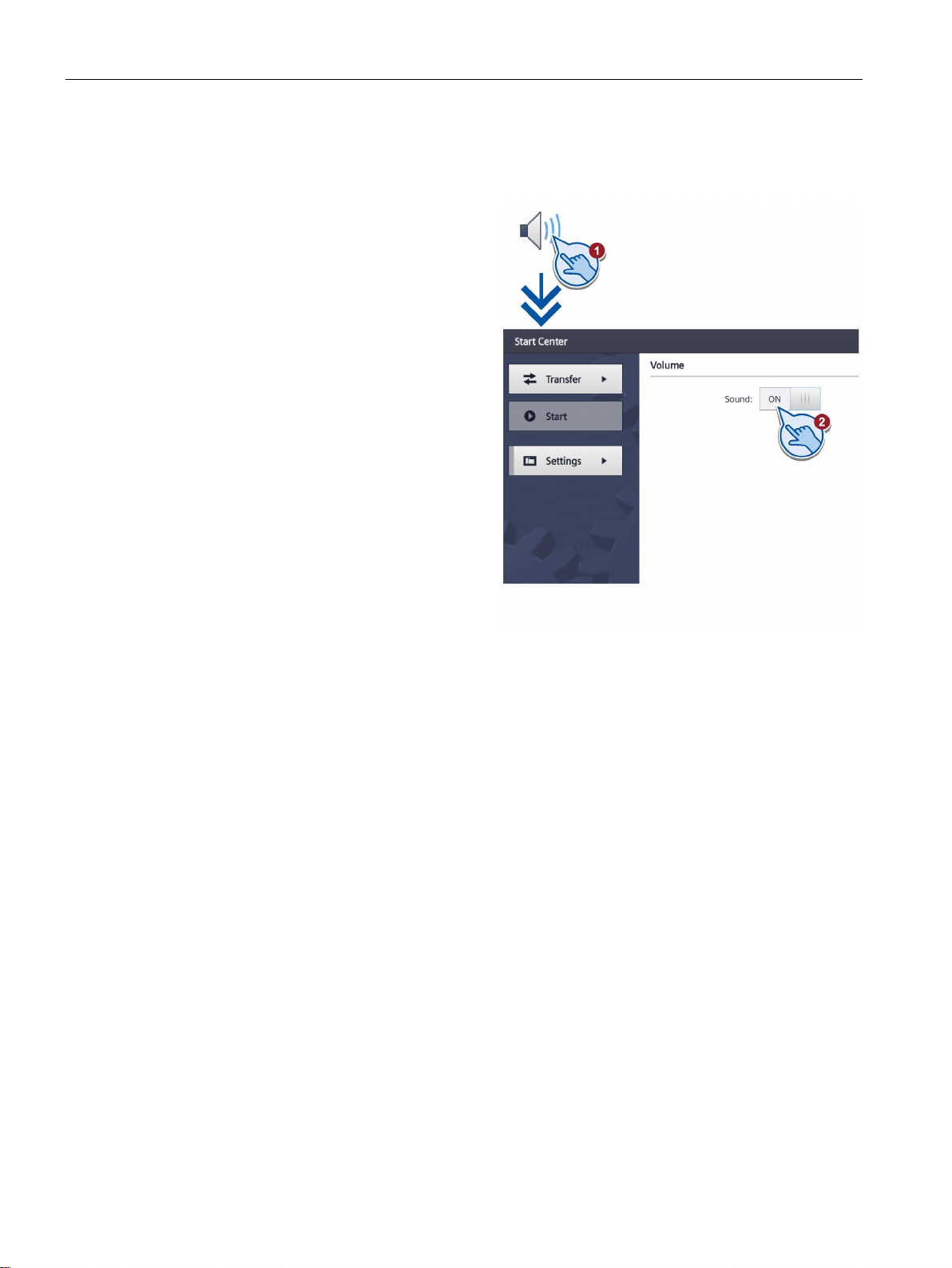
Configuring the device
5.11
Activating the acoustic signal
1.
2.
5.11 Activating the acoustic signal
Touch the "Sounds" icon.
Set the "Sound" switch to "ON".
Once you have set "Sound" to
"ON", you receive acoustic
feedback when you touch the
touch screen in the active project.
Basic Panels 2nd Generation
58 Operating Instructions, 10/2016, A5E33293231-AB
Page 59
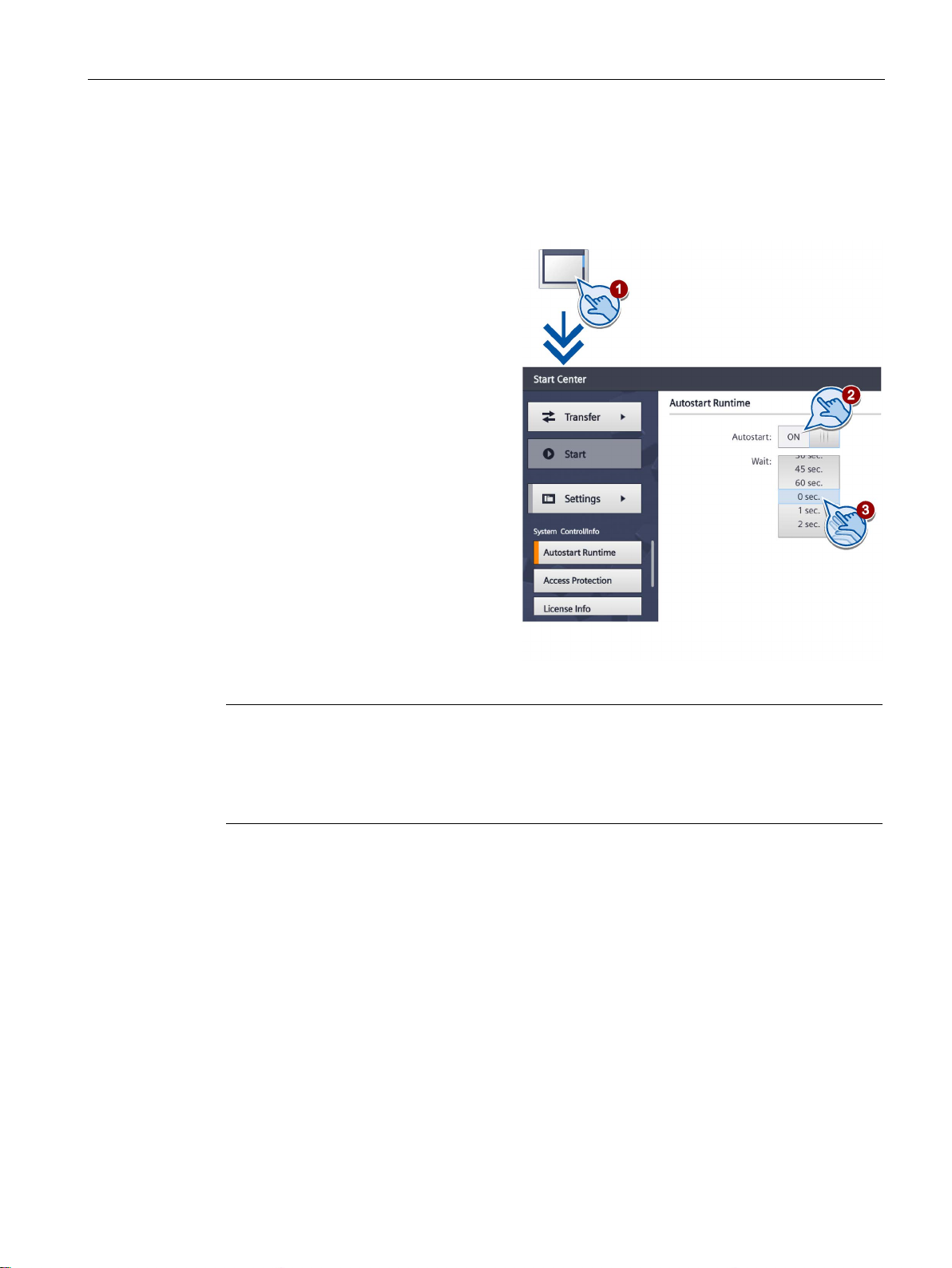
Configuring the device
5.12
Configuring Autostart or wait time
1.
2.
3.
Note
Immediate start of the project with a delay time of 0 seconds
The project starts immediately if a delay time of 0 seconds is set. It is now no longer possible
to call the Start Center after switching on the HMI device. To handle this situation, you need
to configure an operating element with the "Close project" function.
5.12 Configuring Autostart or wait time
You specify in the "System Control/Info" dialog whether the project starts immediately after
the device powers up or after a wait time.
Touch the "System Control/Info" icon.
Set the "Autostart" switch to "ON".
Set the wait time with the
selection wheel under "Wait".
The wait time is the time in seconds
between the appearance of the Start
Center and the automatic start of the
project.
Value range: 0 ... 60 sec.
Basic Panels 2nd Generation
Operating Instructions, 10/2016, A5E33293231-AB
59
Page 60
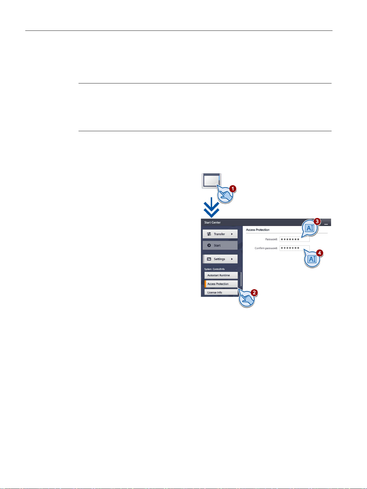
Configuring the device
5.13
Changing the password settings
Note
The password must not contain spaces or the following special characters:
If the password is no longer available for the Start Center, you first have to update the
operati
device will be overwritten when you update the operating system.
Activating password protection
1.
2.
3.
4.
5.13 Changing the password settings
Password protection prevents unauthorized access to the Start Center.
* ? . % / \ ' ".
ng system before you can make any changes in the Start Center. All data on the HMI
Touch the "System Control/Info" icon.
Press the "Access Protection" button.
Enter a password in the "Password"
text box. Touch the text box. The
alphanumerical screen keyboard is
displayed.
Confirm the password in the
"Confirm Password" text box.
Basic Panels 2nd Generation
60 Operating Instructions, 10/2016, A5E33293231-AB
Page 61
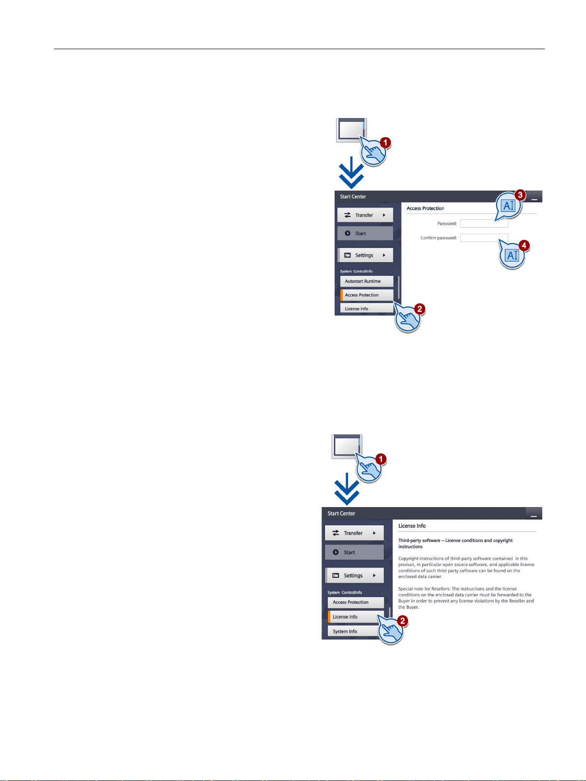
Configuring the device
Deactivating password protection
1.
2.
3.
4.
5.14
Displaying licensing information for the HMI device
1.
2.
5.14 Displaying licensing information for the HMI device
Touch the "System Control/Info" icon.
Press the "Access Protection" button.
Delete the entries in the "Password"
text box.
Delete the entries in the
"Confirm Password" text box.
Touch the "System Control/Info" icon.
Press the "License Info" button to
display license information for the
HMI device software.
Basic Panels 2nd Generation
Operating Instructions, 10/2016, A5E33293231-AB
61
Page 62
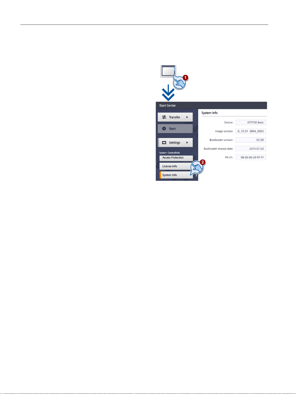
Configuring the device
5.15
Displaying information about the HMI device
1.
2.
3.
5.15 Displaying information about the HMI device
Touch the "System Control/Info" icon.
Shift the bookmarks up in the
navigation area.
Change to the "System Info" tab.
The "System Info" tab is used to
display specific information on the
HMI device. You will need this
information when contacting
Technical Support.
– "Device": HMI device name
– "Image version": Version of
the HMI device image
– "Bootloader version": Version
of the bootloader
– "Bootloader release date":
Release date of the boot loader
– "PN X1": MAC address, only for
HMI devices with PROFINET
interface
Basic Panels 2nd Generation
62 Operating Instructions, 10/2016, A5E33293231-AB
Page 63
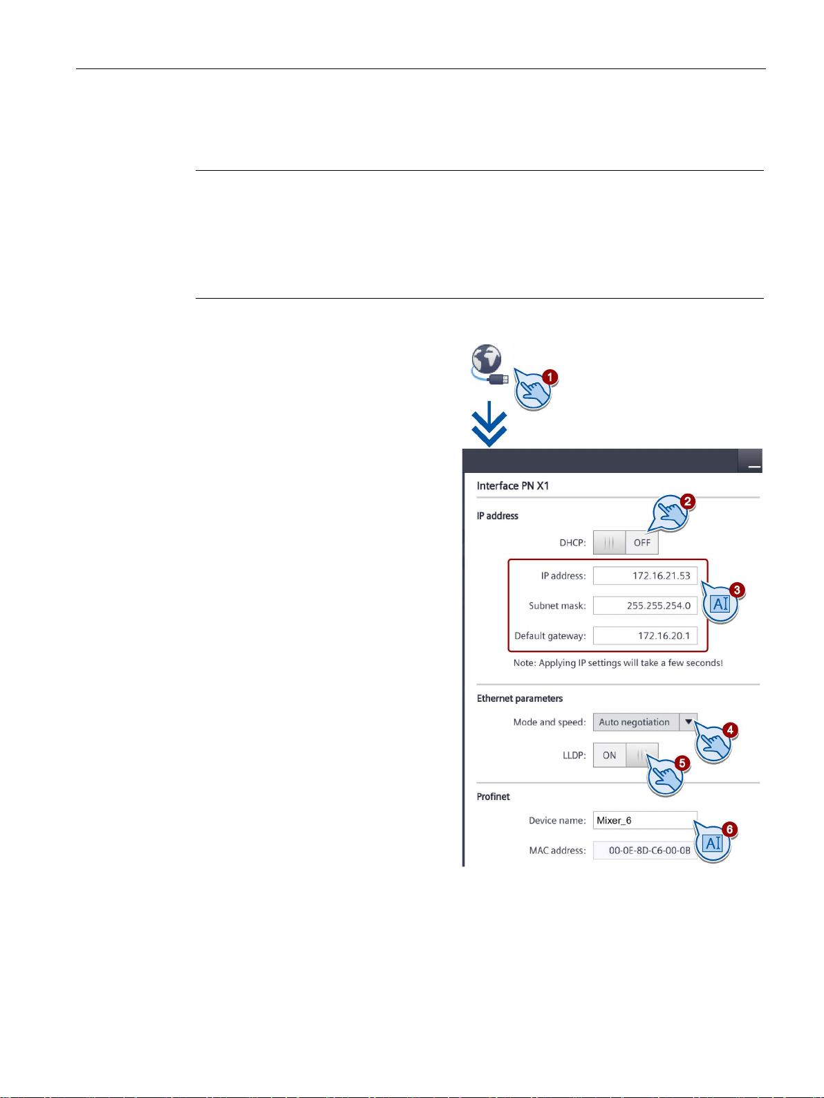
Configuring the device
5.16
Change network settings of PROFINET devices
Note
Communication errors caused by IP address conflicts
Communication errors can occur if several devices in a network share the same IP address.
Assign a unique IP address to ever
If the IP settings are changed, the HMI device checks when the settings are applied whether
the IP address is unique in the network. If not, an error message is displayed.
1. Touch the "Network Interface" icon.
2.
3.
4.
5.
6.
The PROFINET device name must meet the following conditions:
•
•
5.16 Change network settings of PROFINET devices
Choose either automatic address
assignment via "DHCP", or
user-specific address assignment.
If you assign the address yourself,
enter valid values with the screen
keyboard in the entry fields
"IP address", "Subnet mask" and
possibly "Default gateway".
Select the transmission mode and
speed in the PROFINET network in
the "Mode and speed" selection box
under "Ethernet parameters".
Valid values are 10 Mbps or
100 Mbps and "HDX" (half duplex)
or "FDX" (full duplex).
y HMI device in the network.
If you select the "Auto Negotiation"
entry, the transmission mode and
speed in the PROFINET network will
be automatically detected and set.
If the "LLDP" switch is selected, the
HMI device exchanges information
with other HMI devices.
Enter a network name for your HMI
device in the "Device name" field
under "Profinet".
A maximum of four blocks with up to 63 characters each. Example:
"Press1.Fender.Bodywork.Hall3"
Characters "a" to "z", numbers "0" to "9"; special characters "-" and "."
Basic Panels 2nd Generation
Operating Instructions, 10/2016, A5E33293231-AB
63
Page 64
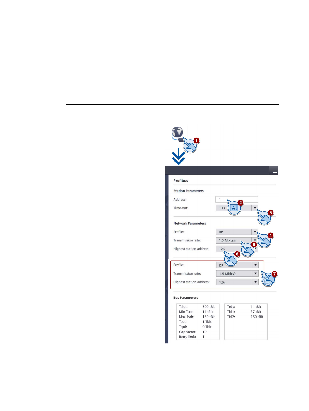
Configuring the device
5.17
Change network settings of PROFIBUS devices
Note
The settings for MPI or PROFIBUS DP communication are defined in the HMI device project.
Edit the transfer settings only in the follow
•
•
1.
2.
3.
4.
5.
6.
7.
5.17 Change network settings of PROFIBUS devices
ing situations:
Initial transfer of a project.
If changes are made to the project but are only applied later
Touch the "Network Interface" icon.
Enter the bus address for the HMI
device in the "Address" text box.
The bus address must be unique
within the MPI/PROFIBUS DP
network.
Enter the time limit for the
PROFIBUS communication in
the "Time-out" text box.
Valid values are 1 s, 10 s, 100 s.
Select the profile from the "Profile"
selection box.
Select the transmission rate from
the "Transmission rate" text box.
Enter the highest station address
on the bus in the "Highest station
address" text box. Valid range of
values: 1 to 126.
The PROFIBUS profile data is
displayed under
"Bus parameters...".
Basic Panels 2nd Generation
64 Operating Instructions, 10/2016, A5E33293231-AB
Page 65
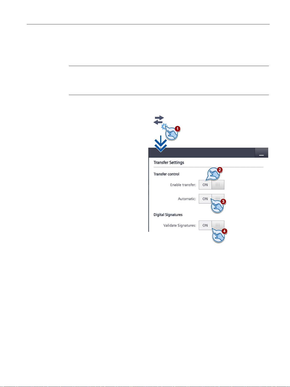
Configuring the device
5.18
Assigning transfer parameters
Note
After the project transfer, you can protect the HMI device against unintentional overwriting of
the project data and HMI device image by locking the data chan
("Enable transfer = OFF").
1. Touch the "Transfer Settings"
icon.
2. Set the "Enable transfer"
switch to "ON".
To enable automatic transfer,
switch "Automatic" to "ON".
When the automatic transfer
is activa
transfer from the configuring
PC while the project is
running. The running project
is closed in this case and the
new project is transferred.
The new project starts after it
is transferred.
4. To select the check of the signature du
"Validate Signatures" = "ON".
This function is available in connection with an HMI device image that is compatible with
WinCC (TIA Portal) V14 or higher. Image signatures are checked starting with V14. If
you t
displayed.
To transfer an unsigned image that is compatible with a version before V14, select
"Validate Signatures" = "OFF".
See also
5.18 Assigning transfer parameters
You must enable one data channel to transfer a project to the HMI device.
nel again
ted, you can start a
ring transfer of an HMI device image, select
ransfer an image that is compatible with a version before V14, an error message is
Change network settings of PROFIBUS devices (Page 64)
Change network settings of PROFINET devices (Page 63)
Basic Panels 2nd Generation
Operating Instructions, 10/2016, A5E33293231-AB
65
Page 66
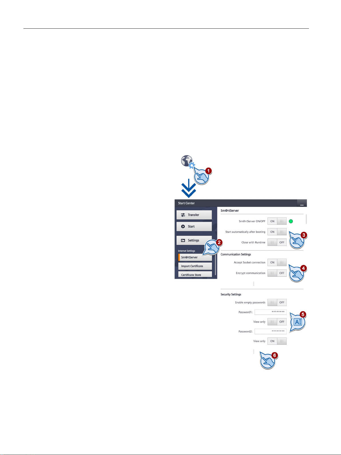
Configuring the device
5.19
Configure Sm@rt Server
Requirement
Procedure
1.
Touch the "Internet Settings" icon.
2. Press the "Sm@rt
3. Select "Start automatically after
booting" if the Sm@rtServer is to
be started together with the HMI
device instead of later with the
project.
Select "Close with Runtime" if
the Sm@rtServer is to be
together with the project.
4. Make sure that the "Accept
Socket connection" switch is in
the "ON" position. Otherwise, a
client connection to the
Sm@rtServer is not possible.
5. Assign secure passwords for
Password 1 and Password 2 for
access of the Sm@rtClients and
select the
if
to observe the HMI device with
this password. Always change
the default passwords.
6. Make other settings, if necessary, such as the ports. You can find additional information
on the settings in m
WinCC Sm@rtServer > Basics > Settings for Sm@rt options > Configurations on the
HMI device > 'Sm@rtServer: Current User Properties' dialog".
5.19 Configure Sm@rt Server
● A Basic Panel with PROFINET interface and an HMI device image compatible with
WinCC (TIA Portal) V14 or higher.
● The HMI device has a Sm@rt Server license that was transferred to the HMI device via
the Automation License Manager.
● The HMI device has a project that was compiled with option
"Runtime settings > Services > Remote control > Start Sm@rtServer".
Server" button.
closed
"View only" checkbox
a Sm@rtClient is only permitted
Basic Panels 2nd Generation
66 Operating Instructions, 10/2016, A5E33293231-AB
anual "WinCC Advanced > Visualize processes > Options >
Page 67
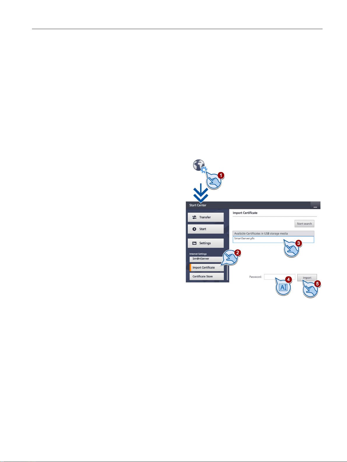
Configuring the device
5.20
Importing a certificate via USB
Requirement
Procedure
1.
2.
3.
4.
5.
5.20 Importing a certificate via USB
The use of certificates increases the information security of web-based communication, e.g.
communication between a Sm@rtClient and the Sm@rtServer.
● A Basic Panel with PROFINET interface and an HMI device image compatible with
WinCC (TIA Portal) V14 or higher.
● A USB memory device with a valid certificate is connected to the Basic Panel.
Touch the "Internet Settings" icon.
Press the "Import Certificate"
button.
Select the desired certificate.
If the certificate is password-
protected, enter the password for
the certificate under "Password".
Press the "Import" button.
Basic Panels 2nd Generation
Operating Instructions, 10/2016, A5E33293231-AB
67
Page 68
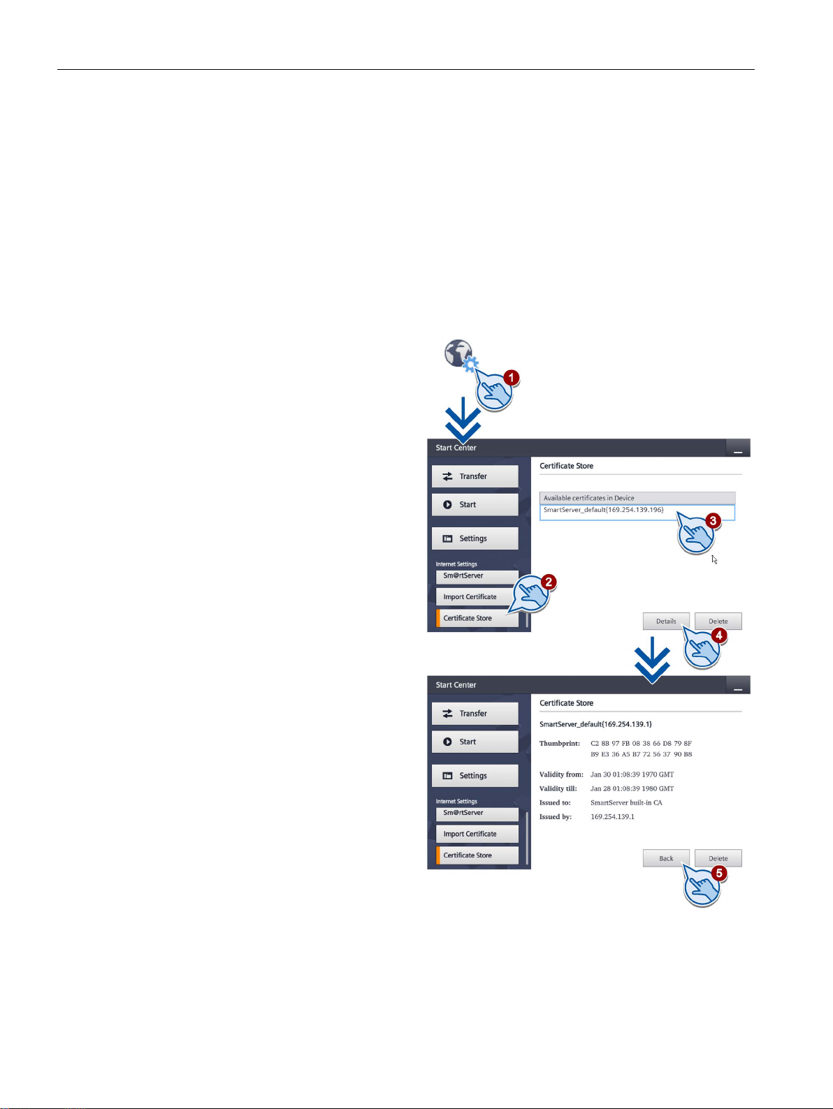
Configuring the device
5.21
Displaying and deleting certificates
Requirement
Procedure
1.
2.
3.
4.
5.
5.21 Displaying and deleting certificates
● A Basic Panel with PROFINET interface and an HMI device image compatible with
WinCC (TIA Portal) V14 or higher.
● A USB memory device is connected to the Basic Panel.
Touch the "Internet Settings" icon.
Press the "Certificate Store" button.
Select the desired certificate.
If you want to display information
about the selected certificate,
press the "Details" button.
You can delete the selected
certificate on the HMI device
using the "Delete" button.
To close the detailed view of
the certificate, press the "Back"
button.
You can delete the selected
certificate on the HMI device
using the "Delete" button.
Basic Panels 2nd Generation
68 Operating Instructions, 10/2016, A5E33293231-AB
Page 69
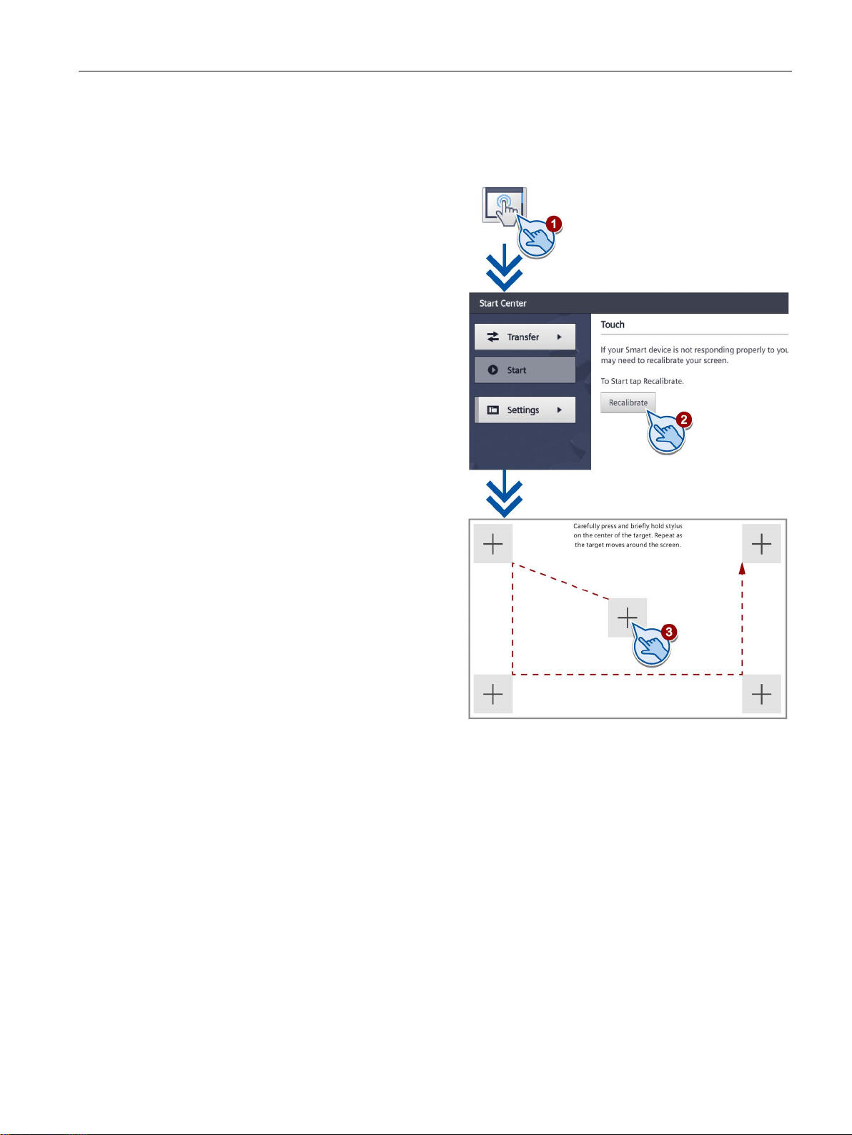
Configuring the device
5.22
Calibrating the touch screen
1.
2. Press the "Recalibrate" button and
3.
crosses within the expected range,
5.22 Calibrating the touch screen
Touch the "Touch" icon.
then press any spot on the touch
screen within the next 15 seconds.
Touch the five calibration crosses
one after the other.
If you have not touched a
calibration cross within the
expected range, calibration
will start once again.
If you have touched all calibration
calibration is complete and will be
saved.
Basic Panels 2nd Generation
Operating Instructions, 10/2016, A5E33293231-AB
69
Page 70
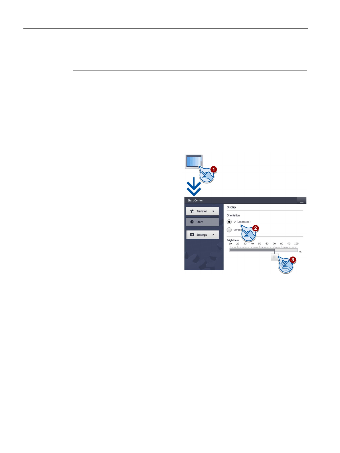
Configuring the device
5.23
Changing the monitor settings
Note
Orientation of the screen (portrait or landscape)
The screen orientation is defined by the configuration engineer in the course of project
creation. The appropriate screen orientation is set automatically when you transfer the
project to the
Do not make any changes to the screen orientation if a project exists on the HMI device with
a different orientation. The screen content may otherwise be truncated.
1.
2.
3.
5.23 Changing the monitor settings
HMI device.
Touch the "Display" icon.
Select the screen orientation:
– "0° (Landscape)" for landscape
– "90° (Portrait)" for portrait
Use the "Brightness" slider to set
the screen brightness. Value
range: 10 ... 100%
You can set the display brightness of the HMI device to a value between 0% and 100% with
the "SetBrightness" system function. If the brightness is set to 0% and the screen saver
switches on, touching the display or a key will switch off the screen saver. The brightness
then changes back to the value that was set before the system function was called.
If the "Display" dialog is opened in the Start Center after use of the "Set Brightness" function,
a brightness between 1 and 10% is set to 10%. Otherwise, the brightness is set to the value
stored in the Start Center.
Basic Panels 2nd Generation
70 Operating Instructions, 10/2016, A5E33293231-AB
Page 71
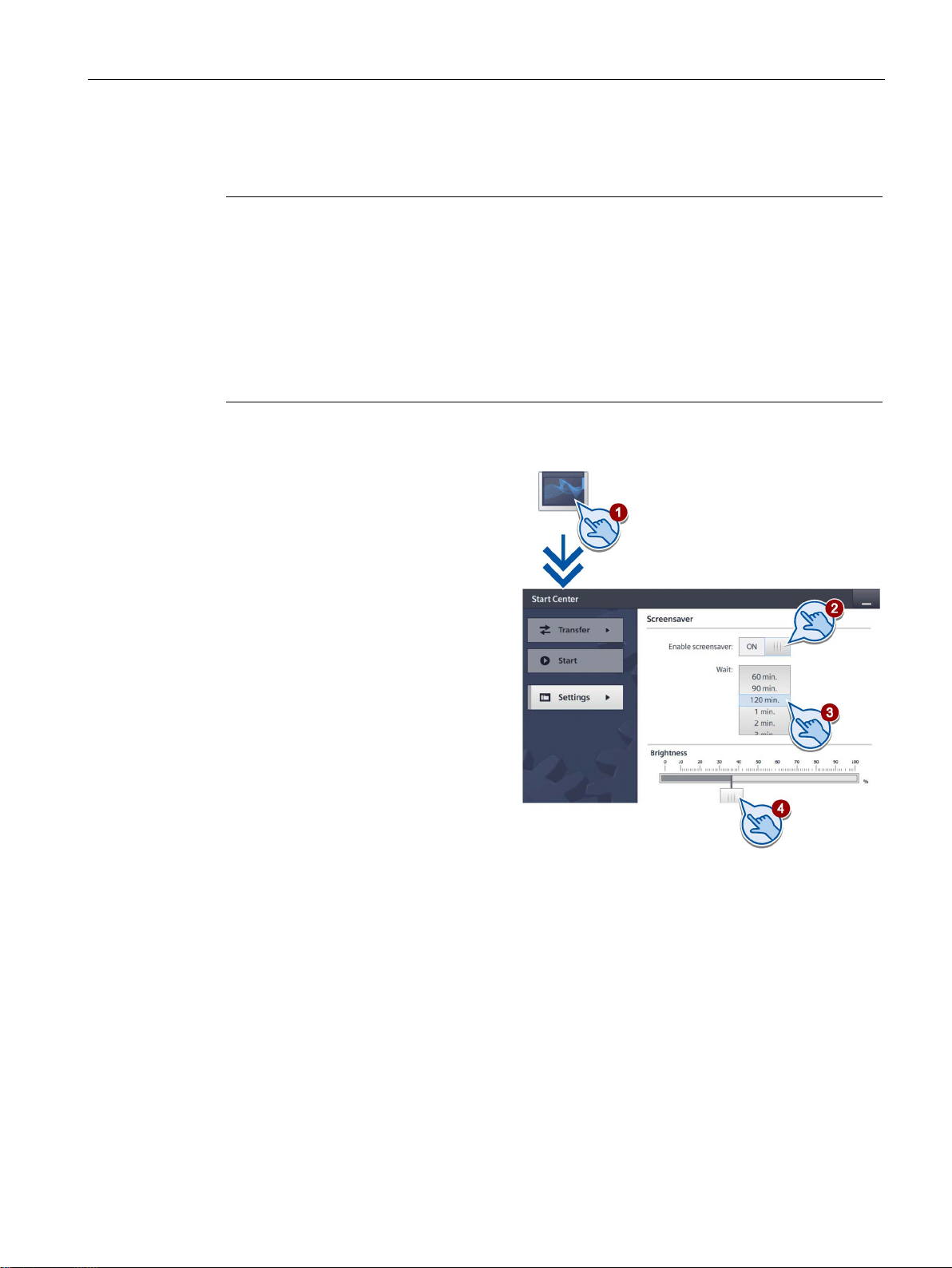
Configuring the device
5.24
Setting the screen saver
Note
Burn-in effect
The screen contents may leave a faint version (ghost) of the image in the background if they
appear for too long.
The "ghost" will disappear automatically after some time. The longer the same content is
displayed on the screen,
The screen saver helps to prevent burn
Always use the screen saver.
1.
2.
3.
4.
ss for when the
between 10% and 100%.
5.24 Setting the screen saver
the longer it will take for the burn-in effect to disappear.
-in.
Press "Screensaver" to open the
"Screensaver" dialog.
Switch on the screensaver with
"Enable screensaver".
Enter the number of minutes
with the selection wheel before
the screen saver is to be activated
under "Wait".
You may select values between
1 and 120 minutes.
Use the "Brightness" slider to set
the screen brightne
screensaver is active.
Possible values:
0% (black screen), integer value
Basic Panels 2nd Generation
Operating Instructions, 10/2016, A5E33293231-AB
71
Page 72

Configuring the device
5.24 Setting the screen saver
Basic Panels 2nd Generation
72 Operating Instructions, 10/2016, A5E33293231-AB
Page 73

6
6.1
Overview
Configuration phase
Process control phase
Transferring the project to the HMI device
Commissioning and recommissioning
A project – the process image of the working process – is created during configuration to
visualize automated working processes. The process displays for the project contain
displays for values and messages which provide information about process statuses. The
process control phase follows the configuration phase.
The project must be transferred to the HMI device if it is to be used in process control.
Another prerequisite for process control is that the HMI device is connected online to a
controller. Current working processes - operating and observing - can then be subject to
process control.
You can transfer a project to an HMI device as follows:
● Transfer from the configuration PC
● Restore from a PC using ProSave
In this case, an archived project is transferred from a PC to the HMI device. The
configuration software does not need to be installed on the PC.
ProSave is a service tool that enables you to manage data on your HMI device. With
ProSave, you can update the operating system of the HMI device, for example, or backup
its data.
● Pack & Go
A project is transferred by means of a storage medium to the HMI device using a PC with
ProSave. The configuration software does not need to be installed on the PC.
Initial startup and recommissioning differ in the following respects:
● With initial startup, there is not project on the HMI device.
The HMI device is also in this state after the operating system has been updated.
● When recommissioning, any project already on the HMI device is replaced.
Basic Panels 2nd Generation
Operating Instructions, 10/2016, A5E33293231-AB
73
Page 74

Commissioning a project
6.2
Operating modes
Operating modes
Changing the operating mode
"Offline" operating mode
"Online" operating mode
"Transfer" mode
6.2 Operating modes
The HMI device may be in the following operating modes:
● Offline
● Online
● Transfer
"Offline mode" and "Online mode" can be set on both the configuration PC and the HMI
device. To set these modes on the HMI device, use a corresponding operating element of
the project.
The configuration engineer must have configured an appropriate operating element to allow
a change of the operating mode on the HMI device during ongoing operation.
Additional information may be available in your system documentation.
In this mode, there is no communication between the HMI device and the controller. Even
though the HMI device can be operated, it cannot exchange data with the controller.
In this mode, the HMI device and the controller communicate with each other. You can
operate the system on the HMI device according to your system configuration.
In this mode, you can transfer a project from the configuration PC to the HMI device, for
example, or backup and restore HMI device data.
The following options are available for setting "Transfer" mode on the HMI device:
● When the HMI device starts up
Start "Transfer" mode manually in the HMI device Loader.
● During ongoing operation
Start the "Transfer" mode manually within the project using an operating element. The
HMI device toggles to "Transfer" mode when automatic mode is set and a transfer is
initiated on the configuration PC.
Basic Panels 2nd Generation
74 Operating Instructions, 10/2016, A5E33293231-AB
Page 75

Commissioning a project
6.3
Data transmission options
Overview
Action
Data channel
Basic Panels DP
Basic Panels
with PROFINET
interface
MPI/PROFIBUS DP
Yes
-
USB
Yes
Yes
MPI/PROFIBUS DP
-
-
PROFINET - Yes
USB
Yes
Yes
connections
6.4
Transfer
6.4.1
Overview
6.4.2
Starting the manual transfer
Introduction
6.3 Data transmission options
The following table shows the options for data transfer between the HMI device and the
configuration PC.
Backup/restore,
Update operating system,
Transfer project
Update operating system with
"Reset to factory settings"
PROFINET - Yes
Assign IP address and device
name, edit communication
PROFINET - Yes
Transfer the executable project from the configuration PC to the HMI device.
You can start the "Transfer" mode manually or automatically on the HMI device.
Transferred data is written directly to internal flash memory of the HMI device. Assign
parameters of a corresponding data channel before you start the transfer.
Basic Panels 2nd Generation
Operating Instructions, 10/2016, A5E33293231-AB
You can manually switch the HMI device to "Transfer" mode as follows:
● At runtime, using a configured operating element.
● In the Start Center of the HMI device.
75
Page 76

Commissioning a project
Requirements
Procedure
Result
6.4 Transfer
● The project is open in WinCC.
● The project is compiled.
● The HMI device is connected to a configuration PC.
● The data channel parameters are assigned on the HMI device.
● The HMI device is in "Transfer" mode.
If you are loading a project to an HMI device for the first time, the "Advanced loading" dialog
is automatically opened. You configure the appropriate interface parameters in this dialog.
For further information, refer to the WinCC documentation.
Proceed as follows:
1. If you want to load a project simultaneously to several HMI devices, use multiple selection
to select all the desired HMI devices in the project tree.
2. Select the "Load to device > Software" command in the shortcut menu of an HMI device.
3. When the "Advanced loading" dialog appears, configure the "Settings for loading":
– Select the interface via which the project will be loaded.
– Configure the corresponding interface parameters.
– Click on "Load".
You can open the "Advanced loading" dialog at any time with the menu command
"Online > Advanced loading to device…".
The "Load preview" dialog" opens. The project is compiled at the same time. The result is
displayed in the "Load preview" dialog.
4. Check the displayed default settings and edit them, if necessary.
5. Click on "Load".
The project is available on the HMI device following successful transfer. If the "Autostart"
function is activated in the Start Center, the transferred project is started automatically.
Basic Panels 2nd Generation
76 Operating Instructions, 10/2016, A5E33293231-AB
Page 77

Commissioning a project
6.4.3
Starting the transfer automatically
Introduction
Note
If automatic transfer is activated on the HMI device and a transfer is initiated on the
configuration PC, the project currently running is automatically stopped. The HMI device then
automatically switches to "Transfer" mode.
After the
cannot be inadvertently switched to transfer mode. Transfer mode can trigger unintentional
actions in the system.
You can issue a password in the Start Center to restrict access
thus avoid unauthorized modifications.
Requirements
Procedure
6.4 Transfer
If automatic transfer is activated, the HMI device automatically changes to "Transfer" mode
at runtime as soon as a transfer is started on the connected configuration PC.
Automatic transfer is particularly suited for the test phase of a new project because transfer
is completed without interfering with the HMI device.
commissioning phase, deactivate the automatic transfer so that the HMI device
to the transfer settings and
● The project is open in WinCC.
● The project is compiled.
● The HMI device is connected to a configuration PC.
● The data channel parameters are assigned on the HMI device.
● The automatic transfer is enabled in the Start Center.
If you are loading a project to an HMI device for the first time, the "Advanced loading" dialog
is automatically opened. You configure the appropriate interface parameters in this dialog.
For further information, refer to the WinCC documentation.
Proceed as follows:
1. If you want to load a project simultaneously to several HMI devices, use multiple selection
to select all the desired HMI devices in the project tree.
2. Select the "Load to device > Software" command in the shortcut menu of an HMI device.
Basic Panels 2nd Generation
Operating Instructions, 10/2016, A5E33293231-AB
77
Page 78

Commissioning a project
Result
6.4.4
Testing a project
Introduction
Note
You should always test the project on the HMI device on which the project will be used.
6.4 Transfer
3. When the "Advanced loading" dialog appears, configure the "Settings for loading":
– Select the interface via which the project will be loaded.
– Configure the corresponding interface parameters.
– Click on "Load".
You can open the "Advanced loading" dialog at any time with the menu command
"Online > Advanced loading to device…".
The "Load preview" dialog" opens. The project is compiled at the same time. The result is
displayed in the "Load preview" dialog.
4. Check the displayed default settings and edit them, if necessary.
5. Click on "Load".
The configuration PC checks the connection to the HMI device. The HMI device shuts down
the current project and automatically changes to "Transfer" mode. The project is transferred
to the HMI device. An error message is displayed on the configuration PC if the connection is
not available or disrupted.
The project is available on the HMI device following successful transfer. The transferred
project is started automatically.
You have the following options to test a project:
● Test the project on the configuration PC
You can test a project on a configuration PC, using a simulator. You can find more
detailed information on this in the WinCC online help.
● Offline testing of the project on the HMI device
Offline testing means that communication between the HMI device and controller is down
while the test is being carried out.
● Online testing of the project on the HMI device
Online testing means that the HMI device and the controller communicate with each other
during testing.
Perform the tests, starting with the "Offline test", followed by the "Online test".
Basic Panels 2nd Generation
78 Operating Instructions, 10/2016, A5E33293231-AB
Page 79

Commissioning a project
Requirement for offline testing
Procedure
Requirement for online testing
Procedure
6.4 Transfer
Check the following:
1. Check the correct layout of the screens.
2. Check the screen navigation.
3. Check the input objects.
4. Enter the tag values.
The test ensures that the project will run as you intended on the HMI device.
● The project has been transferred to the HMI device.
● The HMI device is in "Offline" mode.
In "Offline" mode, you can test individual project functions on the HMI device without them
being affected by the controller. Controller tags, therefore, are not updated.
Test the operating elements and visualization of the project as far as possible without
connecting to the controller.
● The project has been transferred to the HMI device.
● The HMI device is in "Online" mode.
In "Online" mode, you can test individual project functions on the HMI device without them
being affected by the controller. Controller tags are updated in this case.
You have the option to test all communication-dependent functions, for example alarms, etc.
Test the operating elements and views of the project.
Basic Panels 2nd Generation
Operating Instructions, 10/2016, A5E33293231-AB
79
Page 80

Commissioning a project
6.5
Backup and restore
6.5.1
Overview
Backup and restore
General information
Note
Power failure
If a complete restore operation is interrupted due to power failure on the HMI device, the
operating system of the HMI device may be deleted. In this case, you have to reset the HMI
device to its factor
Compatibility conflict
If a message is output on the HMI device warning you of a compatibility conflict during the
restore operation, the operating system must be upd
Note
A data transfer can take several minutes, depending on data volume and transmission rate.
Observe the status display. Do not interrupt the data transfer.
See also
6.5 Backup and restore
You can back up and restore the following data in the internal flash memory of the HMI
device with a PC:
● Project and HMI device image
● Password list
● Recipe data
Use one of the following tools for backup and restore:
● WinCC
● ProSave
Data transmission options (Page 75)
Save to external storage medium – Backup (Page 50)
y settings.
ated.
Restore from external storage medium – Restore (Page 51)
Basic Panels 2nd Generation
80 Operating Instructions, 10/2016, A5E33293231-AB
Page 81

Commissioning a project
6.5.2
Backup and restore using ProSave
Requirement
Procedure – Backup
Result
Procedure – Restore
6.5 Backup and restore
● The HMI device is connected to a PC on which ProSave is installed.
● The data channel parameters are assigned on the HMI device.
1. From the Windows start menu, start ProSave on the PC.
2. Select the HMI device type in the "General" tab.
3. Select the type of interconnection for the HMI device and the PC.
Set the connection parameters.
4. Select the data to be backed up in the "Backup" tab.
– "Complete backup" generates a backup copy of configuration data, recipe data and
the HMI device image to a file in PSB format.
5. Select a destination folder and a file name for the "*.psb" backup file.
6. Set "Transfer" mode on the HMI device.
7. Start the backup operation in ProSave with "Start Backup".
The system outputs a message when the backup is completed.
A backup copy of the data is now available on the PC.
1. From the Windows start menu, start ProSave on the PC.
– "Recipes" generates a backup copy of the HMI device's recipe data records in PSB
format.
– "User management" generates a backup copy of the HMI device's user data in PSB
format.
If automatic transfer mode is enabled on the HMI device, the HMI device automatically
sets "Transfer" mode when a backup is initiated.
Follow the instructions in ProSave.
A progress bar opens to indicate the progress of the operation.
2. Select the HMI device type in the "General" tab.
3. Select the type of interconnection for the HMI device and the PC.
4. Set the connection parameters.
Basic Panels 2nd Generation
Operating Instructions, 10/2016, A5E33293231-AB
81
Page 82

Commissioning a project
Result
6.5.3
Backup and restore using WinCC
Requirement
Backup of the data of the HMI device
6.5 Backup and restore
5. Select the "*.psb" backup file to be restored from the "Restore" tab.
You can see the HMI device for which the backup file was created and the type of backup
data the file contains.
6. Set "Transfer" mode on the HMI device.
If automatic transfer mode is enabled on the HMI device, the device automatically sets
"Transfer" mode when a restore operation is initiated.
7. Start the restore operation in ProSave on the PC with "Start Restore".
8. Follow the instructions in ProSave.
A progress bar indicates the progress of the operation.
When the restore is successfully completed, the data backed up on the PC is now on the
HMI device.
● The HMI device is connected to the configuration PC or the PC with ProSave.
● The HMI device is selected in the project navigation.
● If a server is used for data backup: The HMI device has access to the server.
1. Select the "Backup" command from the "Online > HMI device maintenance" menu.
The "SIMATIC ProSave" dialog box opens.
2. Select the data to backup for the HMI device under "Data type".
3. Enter the name of the backup file under "Save as".
4. Click "Start Backup".
This starts the data backup. The backup operation takes some time, depending on the
connection selected.
Basic Panels 2nd Generation
82 Operating Instructions, 10/2016, A5E33293231-AB
Page 83

Commissioning a project
Restoring the data of the HMI device
6.6
Updating the operating system - Basic Panel DP
6.6.1
Overview
Updating the operating system
Note
Data loss
All data on the HMI device, such as the project and licenses, will be deleted when you
update the operating system.
Note
Calibrating the touch screen
After the update, you may have to recalibrate the touch screen.
See also
6.6 Updating the operating system - Basic Panel DP
1. Select the "Restore" command from the "Online > HMI device maintenance" menu.
2. Enter the name of the backup file under "Save as".
Information about the selected backup file is displayed under "Content".
3. Click "Start Restore".
This starts the restoration. This operation takes some time, depending on the connection
selected.
A compatibility conflict may occur when transferring a project to the HMI device. This is
caused by different versions of the configuration software used and the HMI device image
available on the HMI device. If there are different versions, the transfer is aborted. A
message indicating a compatibility conflict is displayed on the configuration PC.
There are two ways to match the versions:
● Update the HMI device image if the project was created with the most recent version of
the configuration software.
● Transfer a matching version of the HMI device image if you do not want to adapt the
project for the HMI device to the most recent version of the configuration software for the
project.
Update operating system from external storage medium (Page 53)
Basic Panels 2nd Generation
Operating Instructions, 10/2016, A5E33293231-AB
83
Page 84

Commissioning a project
6.6.2
Resetting the factory settings
Note
Data channel
When resetting to factory settings, all data channel parameters used are reset. The
transfer can only be started following reconfiguration of the data channel.
See also
6.6.3
Updating the operating system using ProSave
Requirement
Procedure
6.6 Updating the operating system - Basic Panel DP
In ProSave or WinCC, you can update the operating system with or without resetting to
factory settings.
● Updating the operating system without reset to factory settings
First, switch into "Transfer" mode on the HMI device or use the automatic transfer
function if the project is active. Then start the operating system update in ProSave or
WinCC.
● Updating the operating system with reset to factory setting
Data transmission options (Page 75)
● The HMI device is connected to a PC on which ProSave is installed.
● The data channel parameters are assigned on the HMI device.
1. From the Windows start menu, start ProSave on the PC.
2. Select the HMI device type in the "General" tab.
3. Select the type of connection between the HMI device and the PC, then set the
connection parameters.
4. Select the "OS Update" tab.
5. Select whether to update the operating system with or without restoring the factory
settings by setting the "Reset to factory settings" check box accordingly.
Basic Panels 2nd Generation
84 Operating Instructions, 10/2016, A5E33293231-AB
Page 85

Commissioning a project
Result
6.7
Updating the operating system - Basic Panel with PROFINET
interface
6.7.1
Overview
Updating the operating system
6.7 Updating the operating system - Basic Panel with PROFINET interface
6. Select the HMI device image file (file type "*.fwf") under "Image path".
The HMI device image files are available under
"Programs\Siemens\Automation\Portal V<
<TIA version>\Images".
The output area provides information on the version of the successfully opened HMI
device image file.
7. Set "Transfer" mode on the HMI device.
If automatic transfer mode is enabled on the HMI device, the device automatically sets
"Transfer" mode when an update is initiated.
8. Select "Update OS" on the PC to run the operating system update.
9. Follow the instructions in ProSave.
A progress bar indicates the progress of the operating system update.
A message is displayed when the operating system update is successfully completed and
the HMI device is restarted.
TIA version
>\Data\Hmi\Transfer\
The transferred image is available on the HMI device.
A compatibility conflict may occur when transferring a project to the HMI device. This is
caused by different versions of the configuration software used and the HMI device image
available on the HMI device. If there are different versions, the transfer is aborted. A
message indicating a compatibility conflict is displayed on the configuration PC.
Basic Panels 2nd Generation
Operating Instructions, 10/2016, A5E33293231-AB
85
Page 86

Commissioning a project
Note
Data loss
All data on the HMI device, such as the project and licenses, will be deleted when you
update the operating system.
Note
Calibrating the touch screen
After the update, you may have to recalibrate the touch screen.
See also
6.7.2
Resetting the factory settings
Note
Data channel
When resetting to factory settings, all data channel parameters used are reset. The
transfer can only be started following reconfiguration of the data channel.
See also
6.7 Updating the operating system - Basic Panel with PROFINET interface
There are two ways to match the versions:
● Update the HMI device image if the project was created with the most recent version of
the configuration software.
● Transfer a matching version of the HMI device image if you do not want to adapt the
project for the HMI device to the most recent version of the configuration software for the
project.
Update operating system from external storage medium (Page 53)
In ProSave or WinCC, you can update the operating system with or without resetting to
factory settings.
● Updating the operating system without reset to factory settings
First, switch into "Transfer" mode on the HMI device or use the automatic transfer
function if the project is active. Then start the operating system update in ProSave or
WinCC.
● Updating the operating system with reset to factory setting
Data transmission options (Page 75)
Basic Panels 2nd Generation
86 Operating Instructions, 10/2016, A5E33293231-AB
Page 87

Commissioning a project
6.7.3
Updating the operating system using ProSave
Requirement
Procedure
Result
6.7 Updating the operating system - Basic Panel with PROFINET interface
● The HMI device is connected to a PC on which ProSave is installed.
● The data channel parameters are assigned on the HMI device.
1. From the Windows start menu, start ProSave on the PC.
2. Select the HMI device type in the "General" tab.
3. Select the type of connection between the HMI device and the PC.
4. Set the connection parameters.
5. Select the "OS-Update" tab.
6. Select the HMI device image file (file type "*.fwf") under "Image path".
The HMI device image files are available under
"Programs\Siemens\Automation\Portal V<TIA version>\Data\Hmi\Transfer\
<TIA version>\Images".
The output area provides information on the version of the successfully opened HMI
device image file.
7. Switch to "Transfer" mode on the HMI device.
If automatic transfer mode is enabled on the HMI device, the device automatically sets
Transfer mode when an update is initiated.
8. Select "Update OS" on the PC to run the operating system update.
9. Follow the instructions in ProSave.
A progress bar indicates the progress of the operating system update.
A message is displayed when the operating system update is successfully completed and
the HMI device is restarted.
The transferred image is available on the HMI device.
Basic Panels 2nd Generation
Operating Instructions, 10/2016, A5E33293231-AB
87
Page 88

Commissioning a project
6.7.4
Updating the operating system using WinCC
NOTICE
Updating the operating system deletes all data on the HMI device
Requirement
Procedure
Result
6.7 Updating the operating system - Basic Panel with PROFINET interface
If possible, you should use the interface with the highest bandwidth for this connection, such
as Ethernet. Updating the operating system via a serial connection can take up to an hour.
When you update the operating system you delete data on the target system. For this
reason, it is advisable to back up the following data:
• User administration
• Recipes
Resetting to factory settings also deletes the License Keys. You should also back up the
License Keys before resetting to factory settings.
● The HMI device is connected to the configuration PC.
● The appropriate data channel is configured on the HMI device.
● The HMI device is selected in the project navigation.
1. Select the "Update operating system" command from the menu under
"Online > HMI device maintenance" on the configuration PC in WinCC.
The "SIMATIC ProSave [OS-Update]" dialog opens. The path to the image of the
operating system has been preset.
2. If necessary, select another path to the operating system image you want to transfer to
the HMI device.
3. Click "Update OS".
This starts the update. The update operation can take time, depending on the connection
selected.
The HMI device is restarted when the operating system update is successfully completed.
The transferred image is available on the HMI device.
Basic Panels 2nd Generation
88 Operating Instructions, 10/2016, A5E33293231-AB
Page 89

Commissioning a project
6.7.5
Resetting to factory settings with ProSave
Requirement
Procedure for setting the PC interface
Procedure for resetting factory settings
Note
Possible address conflicts with incorrect IP address
Do not use a dynamic IP
Specify a unique IP address of the subnet in which the configuration PC is located. For
the duration of the update process, the HMI device is automatically assigned to the
specified address of ProSave.
If th
address for "Reset to factory settings".
6.7 Updating the operating system - Basic Panel with PROFINET interface
● The HMI device is connected with a standard Ethernet cable to a PC on which ProSave is
installed.
1. Select "Start > Control Panel > Set PG / PC interface" on the configuration PC.
2. Select "S7ONLINE (STEP7) -> TCP / IP" from the "Application access point" area.
3. Select the interface which is connected to the HMI device from the "Interface parameter
assignment used" area.
4. Confirm your entries.
1. From the Windows start menu, start ProSave on the PC.
2. Select the HMI device type from the "General" tab, and select "Ethernet" from the
Connection area.
3. Enter an IP address.
configuration for "Reset to factory settings".
e HMI device has already been used with WinCC or ProSave use the existing IP
4. Change to the "OS-Update" tab.
5. Select the "Reset to factory settings" check box.
6. Select the HMI device image file (file type "*.fwf") under "Image path".
The HMI device image files are available in the WinCC installation folder under
"Programs\Siemens\Automation\Portal V<
<TIA version>\Images" or on the WinCC installation DVD.
TIA version
>\Data\Hmi\Transfer\
The output area provides information on the version of the successfully opened HMI
device image file.
Basic Panels 2nd Generation
Operating Instructions, 10/2016, A5E33293231-AB
89
Page 90

Commissioning a project
Result
Note
If you can no longer open the Start Cen
is missing, carry out the steps described above to reset the device to the factory settings and
try again.
Note
Calibrating the touch screen
When the restore operation has been completed, you may have
screen.
6.7.6
Resetting to factory settings with WinCC
NOTICE
Updating the operating system deletes all data on the HMI device
Note
The following is required to restore factory settings using Ethernet:
•
•
You configure the P
"S7ONLINE (STEP7)
6.7 Updating the operating system - Basic Panel with PROFINET interface
7. Select "Update OS" on the PC to start the "Reset to factory settings" process.
8. Follow the instructions in ProSave.
A progress bar indicates the progress of the operating system update.
A message is displayed when the operating system update is successfully completed and
the HMI device is restarted.
The transferred image is available on the HMI device. The factory settings are reset.
ter on the HMI device because the operating system
to recalibrate the touch
When you update the operating system you delete data on the target system. For this
reason, it is advisable to back up the following data:
• User administration
• Recipes
Available IP address
PG/PC interface of the configuration PC that is set to Ethernet TCP/IP
G/PC interface using the Control Panel of the configuration PC. Select
-> TCP/IP" under "Application access point".
Basic Panels 2nd Generation
90 Operating Instructions, 10/2016, A5E33293231-AB
Page 91

Commissioning a project
Requirement
Resetting the HMI device to factory settings
Result
6.8
Reset to factory settings via USB
Procedure
6.8 Reset to factory settings via USB
● The HMI device is connected to the configuration PC.
● The HMI device is selected in the project navigation.
1. Select the "Update operating system" command from the menu under
"Online > HMI device maintenance" on the configuration PC in WinCC.
The "SIMATIC ProSave [OS-Update]" dialog opens. The path to the image of the
operating system has been preset.
2. If necessary, select another path to the operating system image you want to transfer to
the HMI device.
3. Enable "Restore factory settings".
4. Click "Update OS".
This starts the update. The update operation can take time, depending on the connection
selected.
The HMI device is restarted when the operating system update is successfully completed.
The transferred image is available on the HMI device. The factory settings are reset.
1. Download the Recovery Software for Basic Panels from the Internet at the following
address:
Recovery USB stick (https://support.industry.siemens.com/cs/ww/en/ps/14738/dl
2. Copy the Recovery Software to the main directory of a formatted USB memory stick.
3. Switch off the HMI device.
4. Insert the USB memory stick into the USB port of the HMI device.
)
Basic Panels 2nd Generation
Operating Instructions, 10/2016, A5E33293231-AB
91
Page 92
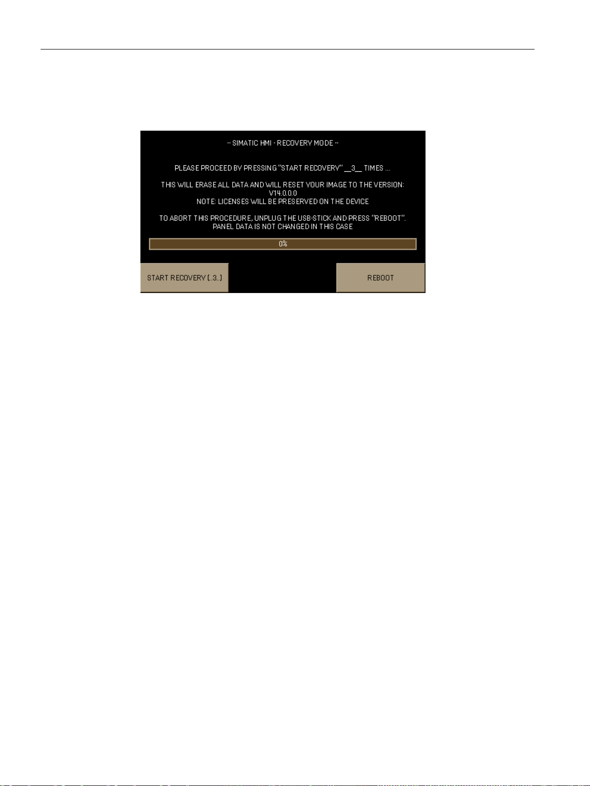
Commissioning a project
6.9
Managing WinCC options
Requirement
6.9 Managing WinCC options
5. Switch on the HMI device.
The HMI device detects the USB memory stick containing the Recovery Software. The
"Recovery Mode" dialog is displayed.
6. To reset the HMI device to factory settings, press the "START RECOVERY (..3..)" button
three times in a row and follow the instructions on the display. At the end of the recovery
operation, remove the USB memory stick and press the "REBOOT" button.
You can install the following WinCC options on an HMI device:
● WinCC options supplied with WinCC for the Engineering System and Runtime
● WinCC options purchased in addition to WinCC for the Engineering System and Runtime
The HMI device type determines which WinCC options can be installed.
For an overview of available WinCC options, refer to "Introduction to WinCC".
● The HMI device is connected to the configuration PC.
● The PG/PC interface is set.
● The HMI device is selected in the project tree.
● The HMI device is switched on.
Basic Panels 2nd Generation
92 Operating Instructions, 10/2016, A5E33293231-AB
Page 93

Commissioning a project
Procedure
See also
6.10
Transferring a license key
Requirement
6.10 Transferring a license key
1. Select the "Options" command in the "Online > HMI device maintenance" menu.
All available WinCC options and those already installed are shown.
2. Click "Device status" to display the WinCC options installed on the HMI device.
3. To install a WinCC option on the HMI device, select the WinCC option with ">>" from the
list of installed WinCC options.
4. Click "<<" to remove a WinCC option from the HMI device.
5. To start the installation or removal, click "OK".
The selected WinCC options have been installed on or removed from the HMI device.
Configure Sm@rt Server (Page 66)
You need a license key for WinCC options to use them on an HMI device. The required
license keys are usually supplied on a storage medium, for example, a USB stick. You can
also obtain a license key from a license server.
● The HMI device is connected to a configuration PC or a PC with the "Automation License
Manager".
The "Automation License Manager" is installed automatically with WinCC.
● If you use a configuration PC:
The HMI device is selected in the project tree.
Basic Panels 2nd Generation
Operating Instructions, 10/2016, A5E33293231-AB
93
Page 94

Commissioning a project
Procedure
6.10 Transferring a license key
1. Open the "Automation License Manager".
2. Start the "Automation License Manager".
– PC without WinCC installation
Open the "Automation License Manager" from the Windows start menu
– PC with WinCC installation
Open the "Automation License Manager" from WinCC as follows:
Select the "Authorize/License" command in the "Online > HMI device maintenance"
menu.
The "Automation License Manager" starts.
3. Select the "Connect HMI device" command in the "Edit > Connect Target System" menu.
The "Connect Target System" dialog is displayed.
4. Select the "device type" of your HMI device.
5. Select the "connection".
6. Configure the corresponding "connection parameters" in line with the selected connection
in the window of the same name.
7. Click "OK".
The connection to the HMI device is established. The connected HMI device is displayed
in the left area of the "Automation License Manager".
8. On the left, select the drive on which the license keys are located.
The license keys are shown on the right.
9. Select the required license keys.
10. Drag-and-drop the license keys to the HMI device.
The license keys are transferred to the HMI device.
To back up the HMI device license keys, drag-and-drop the license keys from the HMI
device to an available drive. License keys can also be removed from the HMI device with
drag-and-drop.
Basic Panels 2nd Generation
94 Operating Instructions, 10/2016, A5E33293231-AB
Page 95

7
7.1
Maintenance and care
Introduction
Requirement
Note
Unintentional response
When cleaning the touch screen, an unintentional response in the controller can be triggered
by tou
Switch the HMI device off before cleaning to prevent unintentional responses.
Note
Damage caused by unauthorized cleaning products
The HMI device may be damaged if compressed air, ste
or scouring powders are used for cleaning purposes.
Do not clean the HMI device with compressed air or steam jet blowers. Do not use
aggressive solvents or scouring powder.
Procedure
The HMI device is designed for maintenance-free operation. Make sure you keep the touch
screen and keyboard membrane clean.
Use a cleaning cloth dampened with a cleaning agent to clean the equipment. Only use
water with a little liquid soap or a screen cleaning foam.
ching keys.
am jet blowers, aggressive solvents
Proceed as follows:
1. Shut down the HMI device.
2. Spray the cleaning solution onto a cleaning cloth.
Do not spray directly onto the HMI device.
3. Clean the HMI device.
When cleaning the display wipe from the screen edge inwards.
Basic Panels 2nd Generation
Operating Instructions, 10/2016, A5E33293231-AB
95
Page 96

Maintenance and care
7.2
Recycling
Recycling and disposal
7.2 Recycling
The HMI devices described in these operating instructions can be recycled due to the low
levels of pollutants. Contact a certified disposal service company for environmentally sound
recycling and disposal of your old devices.
Basic Panels 2nd Generation
96 Operating Instructions, 10/2016, A5E33293231-AB
Page 97

8
8.1
Certificates and approvals
Approvals
Note
The following overview shows possible approvals.
The HMI device itself is approved as shown on the rear panel labels.
IEC 61131
CE approval
EC Declaration of Conformity
The HMI device fulfills requirements and criteria according to IEC 61131-2, Programmable
Logic Controllers, Part 2: Operating resource requirements and tests.
The HMI device meets the general and safety-related requirements of the following EU
directives and conforms to the harmonized European standards (EN) for programmable logic
controllers published in the official gazettes of the European Union:
● 2014/30/EU "Electromagnetic Compatibility" (EMC Directive)
● 2011/65/EU "Directive of the European Parliament and of the Council of 8 June 2011 on
the restriction of the use of certain hazardous substances in electrical and electronic
equipment" (RoHS Directive)
The EC Declarations of Conformity are available to the relevant authorities at the following
address:
Siemens AG
Digital Factory
Factory Automation
DF FA AS SYS
P.O. Box 1963
D-92209 Amberg, Germany
The Declaration of Conformity and other certificates are also available at the following
Internet address:
Certificates for Basic Panels 2nd Generation
(https://support.industry.siemens.com/cs/ww/en/ps/14738/cert
Basic Panels 2nd Generation
Operating Instructions, 10/2016, A5E33293231-AB
)
97
Page 98
Technical specifications
UL approval
RCM Declaration of Conformity for Australia/New Zealand
KOREA
Identification for Eurasion Customs Union
Marine approvals
8.1 Certificates and approvals
Underwriters Laboratories Inc., to
● UL 508 (Industrial Control Equipment)
● CSA C22.2 No. 142 (Process Control Equipment)
This product meets the requirements of the standards:
● AS/NZS 61000.6.4
● IEC 61000-6-4
This product meets the requirements of Korean certification.
This product satisfies the requirement of the Korean Certification (KC Mark).
이 기기는 업무용(A급) 전자파 적합기기로서 판매자 또는 사용자는 이 점을 주의하시기
바라며 가정 외의 지역에서 사용하는 것을 목적으로 합니다.
Note that this device conforms to Limit Class A for emission of radio interference. This
device can be used in all areas except the residential area.
● EAC (Eurasian Conformity)
● Customs union of Russia, Belarus and Kazakhstan
● Declaration of conformity according to Technical Regulations of the Customs Union
(TR CU)
The following marine approvals are provided for the device. After acceptance, the certificates
will be made available under the following address on the Internet: Certificates for Basic
Panels 2nd Generation (https://support.industry.siemens.com/cs/ww/en/ps/14738/cert
● ABS American Bureau of Shipping (USA)
● BV Bureau Veritas (France)
● DNV-GL Det Norske Veritas (Norway)-Germanischer Lloyd
● LR Lloyds Register
● NK Nippon Kaiji Kyokai (Japan)
)
Basic Panels 2nd Generation
98 Operating Instructions, 10/2016, A5E33293231-AB
Page 99

Technical specifications
8.2
Electromagnetic compatibility
8.2.1
Emitted interference
Note
The HMI device is not intended for use in residential areas. Operation of an HMI device in
residential areas can have a negative influence on radio/TV reception.
8.2.2
Immunity to interferences
8.3
Mechanical ambient conditions
8.3.1
Transport and storage conditions
Type of condition
Permitted range
Free fall
≤ 1 m
8.4 ... 500 Hz, acceleration 1 g
Shock to IEC 60068-2-27
250 m/s2, 6 ms, 1000 shocks
8.3.2
Operating Conditions
Type of condition
Permitted range
8.4 ... 200 Hz, acceleration 1 g
Shock according to IEC 60068-2-27
150 m/s2, 11 ms, 3 shocks
8.2 Electromagnetic compatibility
The device is designed for industrial use.
The device meets the requirements according to EN 61000-6-4. The device corresponds to
limit class A.
The device meets the requirements according to EN 61000-6-2.
The following information is for a device that is transported and stored in its original
packaging.
The device meets the requirements according to IEC 60721-3-2, Class 2M2 with the
following amendments and limitations:
Vibration to IEC 60068-2-6 5 ... 8.4 Hz, deflection 3.5 mm
The following information applies to a device installed according to the specifications in these
operating instructions.
The HMI device is designed for stationary operation in a location protected from the effects
of the weather.
The device meets the requirements according to IEC 60721-3-3, Class 3M3 with the
following amendments and limitations:
Vibration according to IEC 60068-2-6 5 ... 8.4 Hz, deflection 3.5 mm
Basic Panels 2nd Generation
Operating Instructions, 10/2016, A5E33293231-AB
99
Page 100

Technical specifications
8.4
Climatic ambient conditions
8.4.1
Long-term storage
Type of condition
Permitted range
Temperature
–20 ... +60 °C
Relative humidity
10 ... 90%, without condensation
8.4.2
Transport and short-term storage
Type of condition
Permitted range
Temperature
–20 ... +60 °C
Atmospheric pressure
1080 ... 660 hPa, corresponds to an elevation of -1000 ... 3500 m
Relative humidity
10 ... 90%, without condensation
H2S: < 0.1 ppm; relative humidity < 60%, no condensation
Note
Ensure that no condensation (dewing) develops on or inside the HMI device after
transporting it at low temperatures or after it has been exposed to extreme temperature
fluctuations.
The HMI d
expose the HMI device to direct radiation from a heater. If dewing has developed, wait
approximately 4 hours until the HMI device has dried completely before switching it on.
8.4 Climatic ambient conditions
The following information applies to a device that is stored for an extended period in its
original packaging.
The device meets the requirements according to IEC 60721-3-1, Class 1K2 with the
following amendments and limitations:
Atmospheric pressure 1080 ... 660 hPa, corresponds to an elevation of -1000 to 3500 m
Pollutant concentration SO2: < 0.5 ppm; relative humidity < 60%, no condensation
S: < 0.1 ppm; relative humidity < 60%, no condensation
H
2
The following information is for a device that is transported and temporarily stored in its
original packaging.
The device meets the requirements according to IEC 60721-3-2, Class 2K2 with the
following amendments and limitations:
Pollutant concentration SO2: < 0.5 ppm; relative humidity < 60%, no condensation
evice must have acquired room temperature before it is put into operation. Do not
Basic Panels 2nd Generation
100 Operating Instructions, 10/2016, A5E33293231-AB
 Loading...