

Page 1

Preface, Contents
User Information
SIMATIC
FM 452
Electronic Cam Controller
Installation and Parameter
Assignment
Manual
This manual is part of the documentation package
with the order number:
6ES7452-1AH00-8BG0
Product Overview
Basics of Cam Control
Installing and Removing the
FM 452
Wiring the FM 452 Electronic
Cam Controller
Installing the Software
Programming the FM 452
Putting the FM 452 into Operation
Reference Information
Machine Data and Cam Data
Settings
1
2
3
4
5
6
7
8
9
02/2000
C79000-G7076-C452
Edition 04
Encoders
Diagnostics
Samples
Appendices
Technical Specifications
Connection Diagrams
Data Blocks/Error Lists
Index
10
11
12
A
B
C
Page 2
Notes on Safety
!
!
!
This manual contains notices which you should observe to ensure your own personal safety, as
well as to protect the product and connected equipment. These notices are highlighted in the manual by a warning triangle and are marked as follows according to the level of danger:
Danger
indicates that death, severe personal injury or substantial property damage will result if proper
precautions are not taken.
Warning
indicates that death, severe personal injury or substantial property damage can result if proper
precautions are not taken.
Caution
indicates that minor personal injury or property damage can result if proper precautions are not
taken.
Note
draws your attention to particularly important information on the product, handling the product,
or to a particular part of the documentation.
Qualified Personnel
Correct Usage
!
Trademarks
The reproduction, transmission or use of this document or its
contents is not permitted without express written authority.
Offenders will be liable for damages. All rights, including rights
created b y patent grant or registration of a utility model or design, are
reserved.
Siemens AG
Bereich Automatisierungs- und Antriebstechnik
Geschaeftsgebiet Industrie-Automatisierungssysteme
Postfach 4848, D-90327 Nuernberg
Only qualified personnel should be allowed to install and work on this equipment. Qualified
persons are defined as persons who are authorized to commission, to ground, and to tag circuits,
equipment, and systems in accordance with established safety practices and standards.
Note the following:
Warning
This device and its components may only be used for the applications described in the catalog or
the technical description, and only in connection with devices or components from other manufacturers which have been approved or recommended by Siemens.
This product can only function correctly and safely if it is transported, stored, set up, and installed correctly, and operated and maintained as recommended.
SIMATIC, SIMATIC NET and SIMATIC NET are registered trademarks of
SIEMENS AG.
Third parties using for their own purposes any other names in this document which refer to trademarks might infringe upon the rights of the trademark owners.
Disclaimer of LiabilityCopyright Siemens AG 1996 All rights reserved
We have checked the contents of this manual for agreement with the
hardware and software described. Since deviations cannot be
precluded entirely, we cannot guarantee full agreement. However,
the data in this manual are reviewed regularly and any necessary
corrections included in subsequent editions. Suggestions for
improvement are welcomed.
Siemens AG 1996
Subject to technical change.
Siemens Aktiengesellschaft C79000-G7076-C452
Page 3
Preface
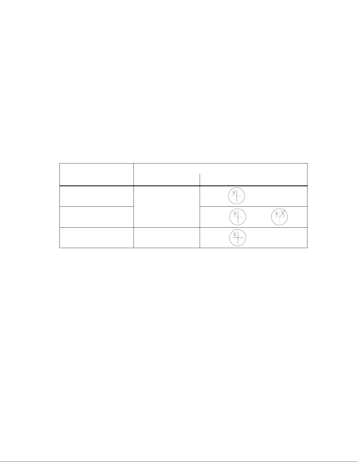
Numb
6ES7 452-1AH00-0AE0
Validity of the Manual
This manual contains the description of the FM 452 electronic cam controller valid
at the time the manual was printed. We reserve the right to describe modifications
in the functionality of the FM 452 in a product information leaflet.
The Manual with the
er in the Page Footer
....
EWA 4NEB 720 6012-02
EWA 4NEB 720 6012-02 a
C79000-G7076-C452 6ES7 452-1AH00-0AE0
MLFB (Order Number) Version
Contents of the Manual
This manual describes the hardware and software of the FM 452 electronic cam
controller.
It consists of the following:
• A section describing basic aspects (Chapters 1 to 7)
• A reference section (Chapters 8 to 12)
• An appendix (Chapters A, B and C)
... is Valid for the FM 452
1 =
2 =
5 =
2
43
3
54
6
87
or
2
43
• An index.
FM 452 Electronic Cam Controller
C79000-G7076-C452-04
iii
Page 4
Preface
Further Support
If you have questions about using the products described in the manual and you
cannot find the answers here, please contact your local Siemens representative.
You will find the addresses, for example, in the appendix ”SIEMENS Worldwide” in
the installation manual
Installation
If you have any questions or comments on this manual, please fill out the remarks
form at the end of the manual and return it to the address shown on the form. We
would be grateful if you could take the time to answer the questions giving your
own personal opinion of the manual.
To help you to become familiar with working with SIMATIC S7 PLCs,
we offer a range of courses.
Please contact your regional training center or the central training center in
D-90027 Nuremberg, Tel. +49 911/895-3202 for more information.
CE Mark
S7-400/M7-400 Programmable Controllers, Hardware and
.
Our products meet the requirements of the EU directive 89/336/EEC
”Electromagnetic Compatibility” and the harmonized European standards (EN)
listed in the directive.
In compliance with the above mentioned EU directive, Article 10, the conformity
declarations are available for the relevant authorities at the following address:
Siemens Aktiengesellschaft
Bereich Automatisierungstechnik
A&D AS E48
Postfach 1963
92209 Amberg
Germany
iv
FM 452 Electronic Cam Controller
C79000-G7076-C452-04
Page 5

Contents
1 Product Overview 1-1. . . . . . . . . . . . . . . . . . . . . . . . . . . . . . . . . . . . . . . . . . . . . . . . . . . . . .
1.1 What is the FM 452? 1-2. . . . . . . . . . . . . . . . . . . . . . . . . . . . . . . . . . . . . . . . . . . . .
1.2 Areas of Application of the FM 452 1-3. . . . . . . . . . . . . . . . . . . . . . . . . . . . . . . .
1.3 Structure of an Electronic Cam Controller with an FM 452 1-4. . . . . . . . . . . .
2 Basics of Cam Control 2-1. . . . . . . . . . . . . . . . . . . . . . . . . . . . . . . . . . . . . . . . . . . . . . . . . .
2.1 Cams 2-2. . . . . . . . . . . . . . . . . . . . . . . . . . . . . . . . . . . . . . . . . . . . . . . . . . . . . . . . . .
2.2 Tracks 2-4. . . . . . . . . . . . . . . . . . . . . . . . . . . . . . . . . . . . . . . . . . . . . . . . . . . . . . . . .
2.2.1 Tracks and Track Result 2-4. . . . . . . . . . . . . . . . . . . . . . . . . . . . . . . . . . . . . . . . . .
2.2.2 Special Tracks 2-6. . . . . . . . . . . . . . . . . . . . . . . . . . . . . . . . . . . . . . . . . . . . . . . . .
2.3 Hysteresis 2-8. . . . . . . . . . . . . . . . . . . . . . . . . . . . . . . . . . . . . . . . . . . . . . . . . . . . . .
2.4 Dynamic Adjustment 2-10. . . . . . . . . . . . . . . . . . . . . . . . . . . . . . . . . . . . . . . . . . . . .
2.5 Interfaces of the Cam Controller 2-11. . . . . . . . . . . . . . . . . . . . . . . . . . . . . . . . . . .
3 Installing and Removing the FM 452 3-1. . . . . . . . . . . . . . . . . . . . . . . . . . . . . . . . . . . . .
4 Wiring the FM 452 Electronic Cam Controller 4-1. . . . . . . . . . . . . . . . . . . . . . . . . . . . .
4.1 Pinout of the Front Connector 4-2. . . . . . . . . . . . . . . . . . . . . . . . . . . . . . . . . . . .
4.2 Wiring the Front Connector 4-5. . . . . . . . . . . . . . . . . . . . . . . . . . . . . . . . . . . . . . .
5 Installing the Software 5-1. . . . . . . . . . . . . . . . . . . . . . . . . . . . . . . . . . . . . . . . . . . . . . . . . .
6 Programming the FM 452 6-1. . . . . . . . . . . . . . . . . . . . . . . . . . . . . . . . . . . . . . . . . . . . . . .
6.1 Basics of Programming an FM 452 6-2. . . . . . . . . . . . . . . . . . . . . . . . . . . . . . . .
6.2 FC CAM_INIT (FC 0) 6-4. . . . . . . . . . . . . . . . . . . . . . . . . . . . . . . . . . . . . . . . . . . .
6.3 FC CAM_CTRL (FC 1) 6-5. . . . . . . . . . . . . . . . . . . . . . . . . . . . . . . . . . . . . . . . . . .
6.4 FC CAM_DIAG (FC 2) 6-10. . . . . . . . . . . . . . . . . . . . . . . . . . . . . . . . . . . . . . . . . .
6.5 FC CAM_MSRM (FC 3) 6-12. . . . . . . . . . . . . . . . . . . . . . . . . . . . . . . . . . . . . . . . .
6.6 Data Blocks 6-14. . . . . . . . . . . . . . . . . . . . . . . . . . . . . . . . . . . . . . . . . . . . . . . . . . . .
6.6.1 Templates for Data Blocks 6-14. . . . . . . . . . . . . . . . . . . . . . . . . . . . . . . . . . . . . . . .
6.6.2 Channel DB 6-14. . . . . . . . . . . . . . . . . . . . . . . . . . . . . . . . . . . . . . . . . . . . . . . . . . . .
6.6.3 Diagnostic DB 6-16. . . . . . . . . . . . . . . . . . . . . . . . . . . . . . . . . . . . . . . . . . . . . . . . . .
6.6.4 Parameter DB 6-16. . . . . . . . . . . . . . . . . . . . . . . . . . . . . . . . . . . . . . . . . . . . . . . . . .
6.7 Interrupts 6-17. . . . . . . . . . . . . . . . . . . . . . . . . . . . . . . . . . . . . . . . . . . . . . . . . . . . . . .
6.8 Technical Specifications 6-19. . . . . . . . . . . . . . . . . . . . . . . . . . . . . . . . . . . . . . . . .
6.9 Fast Access to Module Data 6-21. . . . . . . . . . . . . . . . . . . . . . . . . . . . . . . . . . . . .
6.10 Parameter Transfer Routes 6-22. . . . . . . . . . . . . . . . . . . . . . . . . . . . . . . . . . . . . .
FM 452 Electronic Cam Controller
C79000-G7076-C452-04
v
Page 6

Contents
7 Putting the FM 452 into Operation 7-1. . . . . . . . . . . . . . . . . . . . . . . . . . . . . . . . . . . . . . .
8 Machine Data and Cam Data 8-1. . . . . . . . . . . . . . . . . . . . . . . . . . . . . . . . . . . . . . . . . . . . .
8.1 Writing and Reading the Machine and Cam Data 8-2. . . . . . . . . . . . . . . . . . . .
8.2 System of Units 8-6. . . . . . . . . . . . . . . . . . . . . . . . . . . . . . . . . . . . . . . . . . . . . . . .
8.3 Machine Data of the Axis 8-7. . . . . . . . . . . . . . . . . . . . . . . . . . . . . . . . . . . . . . . . .
8.4 Absolute Encoder Adjustment 8-12. . . . . . . . . . . . . . . . . . . . . . . . . . . . . . . . . . . .
8.5 Machine Data of the Encoder 8-15. . . . . . . . . . . . . . . . . . . . . . . . . . . . . . . . . . . . .
8.6 Resolution 8-20. . . . . . . . . . . . . . . . . . . . . . . . . . . . . . . . . . . . . . . . . . . . . . . . . . . . .
8.7 Number of Cams and Track Data 8-23. . . . . . . . . . . . . . . . . . . . . . . . . . . . . . . . . .
8.8 Interrupt Enable 8-25. . . . . . . . . . . . . . . . . . . . . . . . . . . . . . . . . . . . . . . . . . . . . . . . .
8.9 Cam Data 8-26. . . . . . . . . . . . . . . . . . . . . . . . . . . . . . . . . . . . . . . . . . . . . . . . . . . . . .
9 Settings 9-1. . . . . . . . . . . . . . . . . . . . . . . . . . . . . . . . . . . . . . . . . . . . . . . . . . . . . . . . . . . . . . .
9.1 Influence of Settings on the Switching Response of Time Cams 9-2. . . . . .
9.2 Set Actual Value / Set Actual Value on-the-fly / Cancel Set Actual Value 9-3
9.3 Zero Offset 9-6. . . . . . . . . . . . . . . . . . . . . . . . . . . . . . . . . . . . . . . . . . . . . . . . . . . . .
9.4 Set Reference Point 9-9. . . . . . . . . . . . . . . . . . . . . . . . . . . . . . . . . . . . . . . . . . . . .
9.5 Changing the Cam Edges 9-11. . . . . . . . . . . . . . . . . . . . . . . . . . . . . . . . . . . . . . . .
9.6 Fast Cam Parameter Change 9-13. . . . . . . . . . . . . . . . . . . . . . . . . . . . . . . . . . . . .
9.7 Length Measurement/Edge Acquisition 9-15. . . . . . . . . . . . . . . . . . . . . . . . . . . . .
9.8 Retrigger Reference Point 9-19. . . . . . . . . . . . . . . . . . . . . . . . . . . . . . . . . . . . . . . .
9.9 Deactivating Software Limit Switches 9-22. . . . . . . . . . . . . . . . . . . . . . . . . . . . . .
9.10 Simulation 9-23. . . . . . . . . . . . . . . . . . . . . . . . . . . . . . . . . . . . . . . . . . . . . . . . . . . . . .
9.11 Counted Values of the Counter Cam Tracks 9-25. . . . . . . . . . . . . . . . . . . . . . . . .
9.12 Position and Track Data 9-26. . . . . . . . . . . . . . . . . . . . . . . . . . . . . . . . . . . . . . . . . .
9.13 Encoder Data 9-27. . . . . . . . . . . . . . . . . . . . . . . . . . . . . . . . . . . . . . . . . . . . . . . . . . .
9.14 Cam and Track Data 9-28. . . . . . . . . . . . . . . . . . . . . . . . . . . . . . . . . . . . . . . . . . . . .
9.15 Control Signals for the Cam Controller 9-29. . . . . . . . . . . . . . . . . . . . . . . . . . . . .
9.16 Return Signals for the Cam Controller 9-30. . . . . . . . . . . . . . . . . . . . . . . . . . . . . .
9.17 Return Signals for Diagnostics 9-31. . . . . . . . . . . . . . . . . . . . . . . . . . . . . . . . . . . .
10 Encoders 10-1. . . . . . . . . . . . . . . . . . . . . . . . . . . . . . . . . . . . . . . . . . . . . . . . . . . . . . . . . . . . . .
10.1 Incremental Encoders 10-2. . . . . . . . . . . . . . . . . . . . . . . . . . . . . . . . . . . . . . . . . . .
10.2 Initiators 10-5. . . . . . . . . . . . . . . . . . . . . . . . . . . . . . . . . . . . . . . . . . . . . . . . . . . . . .
10.3 Absolute Encoders 10-6. . . . . . . . . . . . . . . . . . . . . . . . . . . . . . . . . . . . . . . . . . . . . .
FM 452 Electronic Cam Controller
vi
C79000-G7076-C452-04
Page 7

Contents
11 Diagnostics 11-1. . . . . . . . . . . . . . . . . . . . . . . . . . . . . . . . . . . . . . . . . . . . . . . . . . . . . . . . . . . .
11.1 Possibilities for Error Evaluation 11-2. . . . . . . . . . . . . . . . . . . . . . . . . . . . . . . . . . .
11.2 Meaning of the Error LEDs 11-3. . . . . . . . . . . . . . . . . . . . . . . . . . . . . . . . . . . . . .
11.3 Diagnostic Interrupts 11-4. . . . . . . . . . . . . . . . . . . . . . . . . . . . . . . . . . . . . . . . . . . . .
12 Samples 12-1. . . . . . . . . . . . . . . . . . . . . . . . . . . . . . . . . . . . . . . . . . . . . . . . . . . . . . . . . . . . . . .
12.1 Introduction 12-2. . . . . . . . . . . . . . . . . . . . . . . . . . . . . . . . . . . . . . . . . . . . . . . . . . . . .
12.2 Requirements 12-2. . . . . . . . . . . . . . . . . . . . . . . . . . . . . . . . . . . . . . . . . . . . . . . . . . .
12.3 Preparing the Samples 12-3. . . . . . . . . . . . . . . . . . . . . . . . . . . . . . . . . . . . . . . . . . .
12.4 Code of the Samples 12-3. . . . . . . . . . . . . . . . . . . . . . . . . . . . . . . . . . . . . . . . . . . .
12.5 Testing a Sample 12-4. . . . . . . . . . . . . . . . . . . . . . . . . . . . . . . . . . . . . . . . . . . . . . . .
12.6 Adapting a Sample 12-4. . . . . . . . . . . . . . . . . . . . . . . . . . . . . . . . . . . . . . . . . . . . . .
12.7 Sample Program 1 “GettingStarted” 12-5. . . . . . . . . . . . . . . . . . . . . . . . . . . . . . . .
12.8 Sample Program 2 “Commission” 12-7. . . . . . . . . . . . . . . . . . . . . . . . . . . . . . . . . .
12.9 Sample Program 3 “OneModule” 12-9. . . . . . . . . . . . . . . . . . . . . . . . . . . . . . . . . .
12.10 Sample Program 4 “Interrupts” 12-12. . . . . . . . . . . . . . . . . . . . . . . . . . . . . . . . . . . .
12.11 Sample Program 5 “MultiModules” 12-14. . . . . . . . . . . . . . . . . . . . . . . . . . . . . . . . .
A Technical Specifications A-1. . . . . . . . . . . . . . . . . . . . . . . . . . . . . . . . . . . . . . . . . . . . . . . .
B Connection Diagrams B-1. . . . . . . . . . . . . . . . . . . . . . . . . . . . . . . . . . . . . . . . . . . . . . . . . . .
B.1 Connection Diagram for Incremental Encoder Siemens 6FX 2001-2
(Up=5V; RS 422) B-2. . . . . . . . . . . . . . . . . . . . . . . . . . . . . . . . . . . . . . . . . . . . . . . .
B.2 Connection Diagram for Incremental Encoder Siemens 6FX 2001-2
(Up=24V; RS 422) B-3. . . . . . . . . . . . . . . . . . . . . . . . . . . . . . . . . . . . . . . . . . . . . . .
B.3 Connection Diagram for Incremental Encoder Siemens 6FX 2001-4
(Up=24V; HTL) B-4. . . . . . . . . . . . . . . . . . . . . . . . . . . . . . . . . . . . . . . . . . . . . . . . . .
B.4 Connection Diagram for Absolute Encoder Siemens 6FX 2001-5
(Up=24V; SSI) B-5. . . . . . . . . . . . . . . . . . . . . . . . . . . . . . . . . . . . . . . . . . . . . . . . . .
C Data Blocks/Error Lists C-1. . . . . . . . . . . . . . . . . . . . . . . . . . . . . . . . . . . . . . . . . . . . . . . . .
C.1 Content of the Channel DB C-2. . . . . . . . . . . . . . . . . . . . . . . . . . . . . . . . . . . . . . .
C.2 Content of the Parameter DB C-10. . . . . . . . . . . . . . . . . . . . . . . . . . . . . . . . . . . . .
C.3 Data and Structure of the Diagnostic DB C-12. . . . . . . . . . . . . . . . . . . . . . . . . . . .
C.4 Error Classes C-15. . . . . . . . . . . . . . . . . . . . . . . . . . . . . . . . . . . . . . . . . . . . . . . . . . .
Index Index-1. . . . . . . . . . . . . . . . . . . . . . . . . . . . . . . . . . . . . . . . . . . . . . . . . . . . . . . . . . . . . . . .
FM 452 Electronic Cam Controller
C79000-G7076-C452-04
vii
Page 8

Contents
viii
FM 452 Electronic Cam Controller
C79000-G7076-C452-04
Page 9

Product Overview
Chapter Overview
Section Contents Page
1.1 What is the FM 452? 1-2
1.2 Areas of Application of the FM 452 1-3
1.3 Structure of an Electronic Cam Controller with an FM 452 1-4
1
FM 452 Electronic Cam Controller
C79000-G7076-C452-04
1-1
Page 10
Product Overview
1.1 What is the FM 452?
The FM 452 function module is a single-channel, electronic cam controller and is
used in the S7-400 programmable controller. It supports both rotary and linear
axes. When used for position sensing, you can connect initiators, incremental, or
absolute encoders (SSI). As a slave, the FM 452 can listen in on the SSI frame of
an absolute encoder.
You can use up to a maximum of 128 distance or time cams that you can assign to
32 cam tracks as required. The first 16 cam tracks are output via the digital outputs
on the module. For information about the functions and settings of the cam
controller, please refer to the following chapters.
You can operate several FM 452 modules at the same time. Combinations with
other FM/CP modules are also possible. One typical combination is to use the
module in conjunction with an FM 451 positioning module.
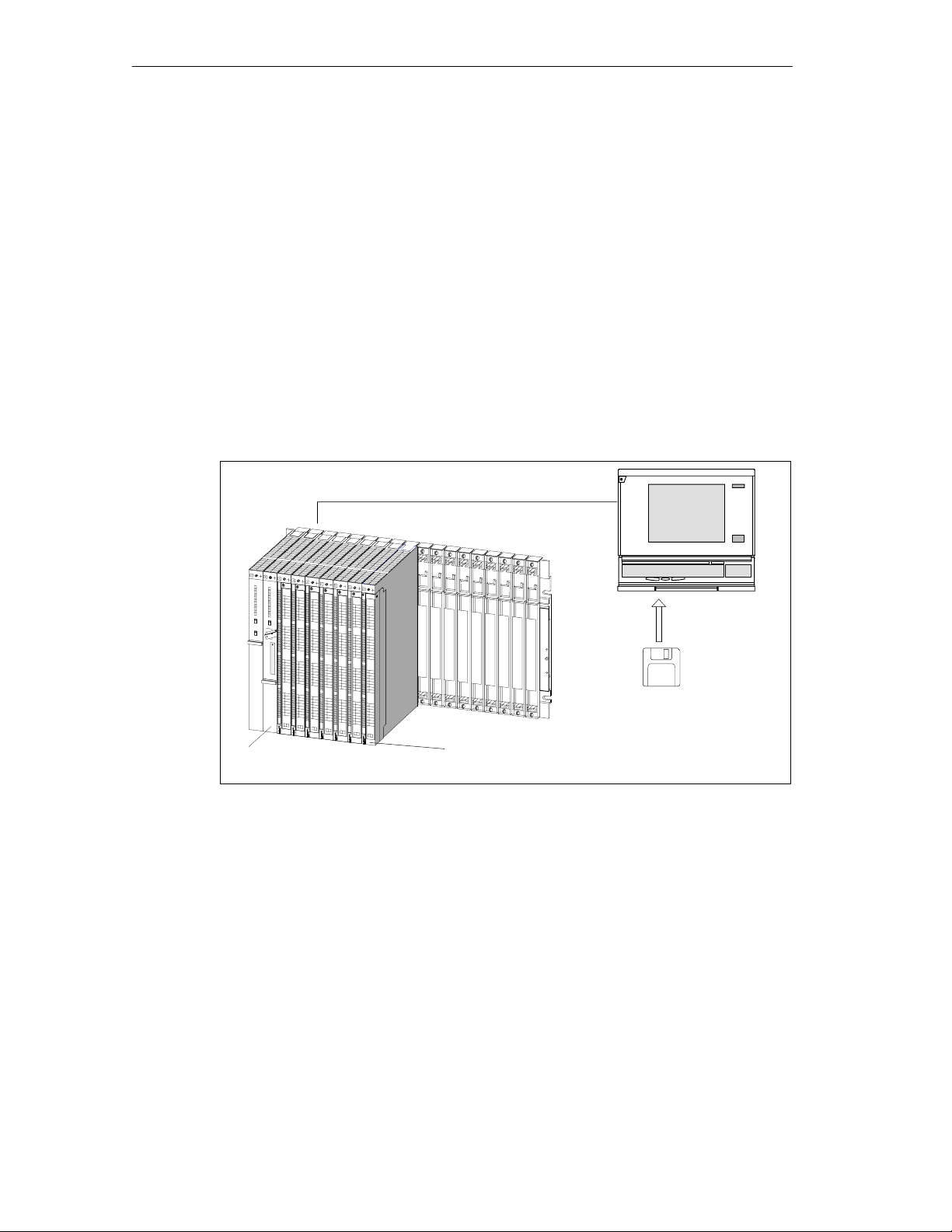
Programming device (PG) with STEP 7 and the
parameter assignment user interface for FM x52
1-2
Configuration package with
parameter assignment user
CPU
with user program and blocks of the FM 452
Figure 1-1 Structure of a SIMATIC S7-400 PLC with an FM 452
FM 452
interface, blocks and manual
FM 452 Electronic Cam Controller
C79000-G7076-C452-04
Page 11
1.2 Areas of Application of the FM 452
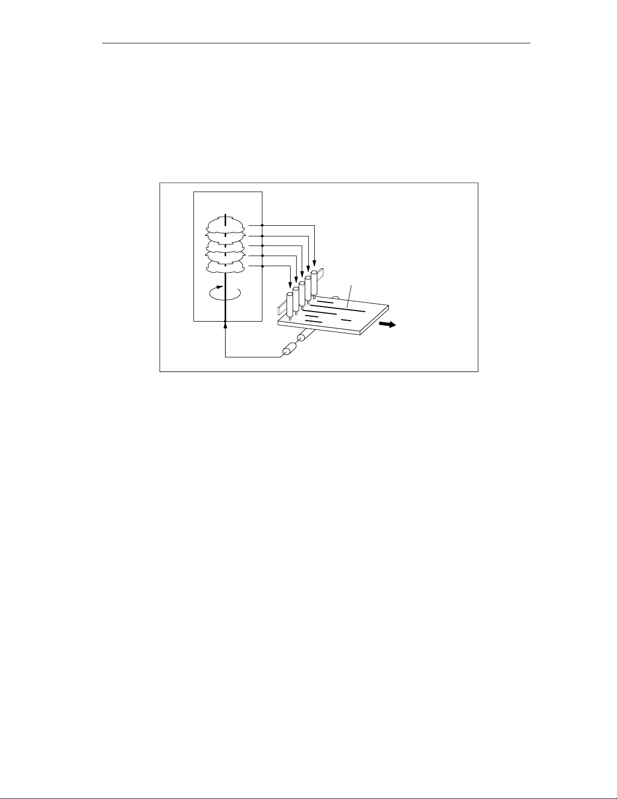
Example: Applying Glue Tracks
In the following example, glue tracks are applied to wooden boards. Each cam
track controls one glue gun via a digital output.
Product Overview
FM 452
Figure 1-2 Example of an Electronic Cam Control Application
Example: Controlling a Press
Another typical application is the automation of an eccentric press with a cam
controller.
This is a rotational process; in other words, after one revolution of the rotary axis,
the function starts again at the beginning.
Typical electronic cam controller tasks in this application include:
• Turning the lubricant supply on and off
• Triggering material feed and removal (for example controlling a gripper)
• Stopping the press at the “upper dead point”
Digital outputs trigger reactions
Q 0
Q 1
Q 2
Q 3
Q 4
Glue tracks
Wooden board
Direction of
transport
Encoder detects axis position
Example: Packaging System
Preserves are packed on a turntable. The electronic cam controller triggers actions
at specific angular positions:
• Placing and folding of cartons on the turntable
• Placing the preserves in the cartons
• Closing the cartons
• Placing the cartons on a conveyor belt
FM 452 Electronic Cam Controller
C79000-G7076-C452-04
1-3
Page 12
Product Overview
1.3 Structure of an Electronic Cam Controller with an FM 452
Electronic Cam Controller
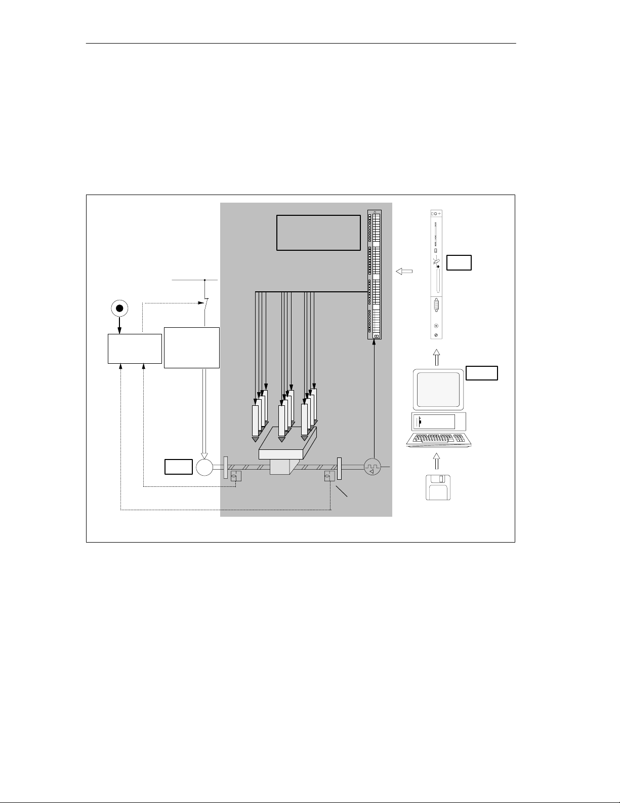
Figure 1-3 shows the components of an electronic cam controller. The schematic is
explained briefly below.
EMER
STOP
Safety
system
Power
supply
Power
controller
Motor
FM 452 Electronic
Cam Controller
Digital outputs Q 0 to 15
Processing
stations
Workpiece
M
Mechanical
transmission
elements
Encoder
Limit switch
11
CPU
PG/PC
Figure 1-3 Electronic Cam Controller
Power Controller and Safety System
The motor is controlled by the power controller. The power controller can consist of
a contactor circuit, for example, controlled by an FM 451 positioning module.
If the safety system responds (EMER STOP or limit switch), the power controller
turns off the motor.
1-4
FM 452 Electronic Cam Controller
C79000-G7076-C452-04
Page 13

Motor
The motor is controlled by the power controller and drives the spindle.
FM 452 Electronic Cam Controller
The electronic cam controller detects the current position of the axis using the
information from an encoder. The encoder signals are evaluated (for example
pulses counted) that are proportional to the distances traveled. Depending on the
actual position, the digital outputs are activated or deactivated (“cams”). The
processing stations are controlled via the digital outputs.
Encoder
The encoder supplies information both about position and direction.
CPU
Product Overview
PG/PC
The CPU executes the user program. Data and signals are exchanged between
the user program and the module using function calls.
You assign the required parameters and program the electronic cam controller on a
programming device or PC.
• Parameter assignment: You set parameters for the FM 452 either using the
parameter assignment user interface or using the parameter DB.
• Programming: You program the FM 452 with function blocks that you
incorporate directly in your user program.
• Testing and putting into operation: You test the FM 452 using the
assignment user interface
operation.
with which you also finally put the system into
parameter
FM 452 Electronic Cam Controller
C79000-G7076-C452-04
1-5
Page 14

Product Overview
1-6
FM 452 Electronic Cam Controller
C79000-G7076-C452-04
Page 15

Basics of Cam Control
Chapter Overview
Section Contents Page
2.1 Cams 2-2
2.2 Tracks 2-4
2.3 Hysteresis 2-8
2.4 Dynamic Adjustment 2-10
2.5 Interfaces of the Cam Controller 2-11
2
FM 452 Electronic Cam Controller
C79000-G7076-C452-04
2-1
Page 16

Basics of Cam Control
2.1 Cams
Types of Cam
With the appropriate parameter settings, each cam can be either a distance cam or
time cam.
Table 2-1 compares the characteristics of both types of cam.
Direction Detection
The direction of movement of the axis is determined as follows:
• With each pulse of an incremental encoder.
• With each error-free frame of an SSI encoder.
2-2
FM 452 Electronic Cam Controller
C79000-G7076-C452-04
Page 17

Table 2-1 Definition and Switching of the Two Cam Types
Distance Cam Time Cam
Representation
Parameter
Settings
The following parameters are required:
• Cam start
Cam length
s
Cam endCam start
• Cam end
• Activation direction
• Lead time
Activation
Direction
Two activation directions are possible:
• Positive: The cam is activated at the
cam start when the axis is moving in
the direction of increasing actual
values.
• Negative: The cam is activated at the
cam end when the axis is moving in
the direction of decreasing actual
values.
You can set both activation directions at
the same time.
Activation The cam is activated:
• At the cam start when the axis is
moving in a positive direction and the
positive activation direction is set.
• At the cam end when the axis is
moving in a negative direction and
the negative activation direction is
set.
• The actual value is within the range
of the cam.
Deactivation The cam is deactivated when:
• The selected distance has been
traveled,
• The activation direction is opposite to
the direction of movement of the axis
and no hysteresis is set,
• The actual value is no longer within
the range of the cam.
Active length The active length of the cam is defined
by the cam start and cam end.
Cam start and cam end belong to the
active section of the cam.
On Time The on time of the cam depends on the
speed at which the axis travels the
active length of the cam.
Basics of Cam Control
Activation
time
Cam start Cam end
The following parameters are required:
s
• Cam start
• Activation time
• Activation direction
• Lead time
Two activation directions are possible:
• Positive: The cam is activated at the
cam start when the axis is moving in
the direction of increasing actual
values.
• Negative: The cam is activated at the
cam start when the axis is moving in
the direction of decreasing actual
values.
You can set both activation directions at
the same time.
The cam is activated:
• At the cam start when the direction of
movement of the axis matches the
activation direction.
After it has been activated, the full cam
activation time elapses even if the
direction of movement of the axis
changes after the cam is activated. If the
cam start is passed again during this
time, the cam is not retriggered.
The cam is deactivated when the
selected time has expired.
The active length of the cam depends on
the speed at which the axis travels while
the cam is active.
The on time of the cam is selected with
the activation time.
FM 452 Electronic Cam Controller
C79000-G7076-C452-04
2-3
Page 18

Basics of Cam Control
2.2 Tracks
2.2.1 Tracks and Track Result
Tracks
With the 32 tracks, you can control a maximum of 32 different switching actions.
You can evaluate the tracks with the return signals.
Each of the first 16 tracks (track 0 to 15) has a digital output (Q0 to Q15) of the
FM 452 assigned to it that can, for example, control a connected contactor directly.
Track Result
You have a maximum of 128 cams available that can be assigned to any track.
Several cams can be assigned to each track. The track result is obtained by the
logical ORing of all cam values of this track (see Figure 2-4, page 2-11).
Example of a Track Result
During parameter assignment, you specify the following cams for track 3:
Cam Cam start Cam end
1 101 m 106 m
2 100 m 104 m
This results in the following track result:
Cam 1
Cam 2
Track result
Track 3
Figure 2-1 Calculating the Track Result
105 m100 m 110 m
s
Track Enable
To allow the track results of tracks 0 to 15 to be applied as track signals to the
digital outputs Q0 to Q15 of the FM 452, the cam tracks you are using must be
enabled.
2-4
FM 452 Electronic Cam Controller
C79000-G7076-C452-04
Page 19

External Enable of Tracks 3 to 10
You can set an external enable for tracks 3 to 10 in the machine data. The track
signals 3 to 10 are then ANDed with digital inputs I3 to I10 before they can switch
the respective digital outputs Q3 to Q10 of the FM 452.
A digital output (Q3 to Q10) is switched when the following conditions are met:
• The relevant track is enabled
• At least one cam on this track is active (track result = 1).
• The corresponding digital input I3 to I10 was set by an external event.
Setting the Track Signals
The track signals 0 to 15 (corresponding to digital outputs Q0 to Q15) can be set
via the cam controller or the CPU.
Basics of Cam Control
FM 452 Electronic Cam Controller
C79000-G7076-C452-04
2-5
Page 20
Basics of Cam Control
2.2.2 Special Tracks
Definition
By setting the relevant parameters, you can set tracks 0 to 2 as special tracks, as
follows:
• Track 0 or 1: Counter cam track
• Track 2: Brake cam track
Requirements
The following requirements must be met to allow the use of the special tracks:
• Cams are assigned to the track
• Cam processing is active
• The relevant track is enabled
• The track is selected as a special track
Counter Cam Track
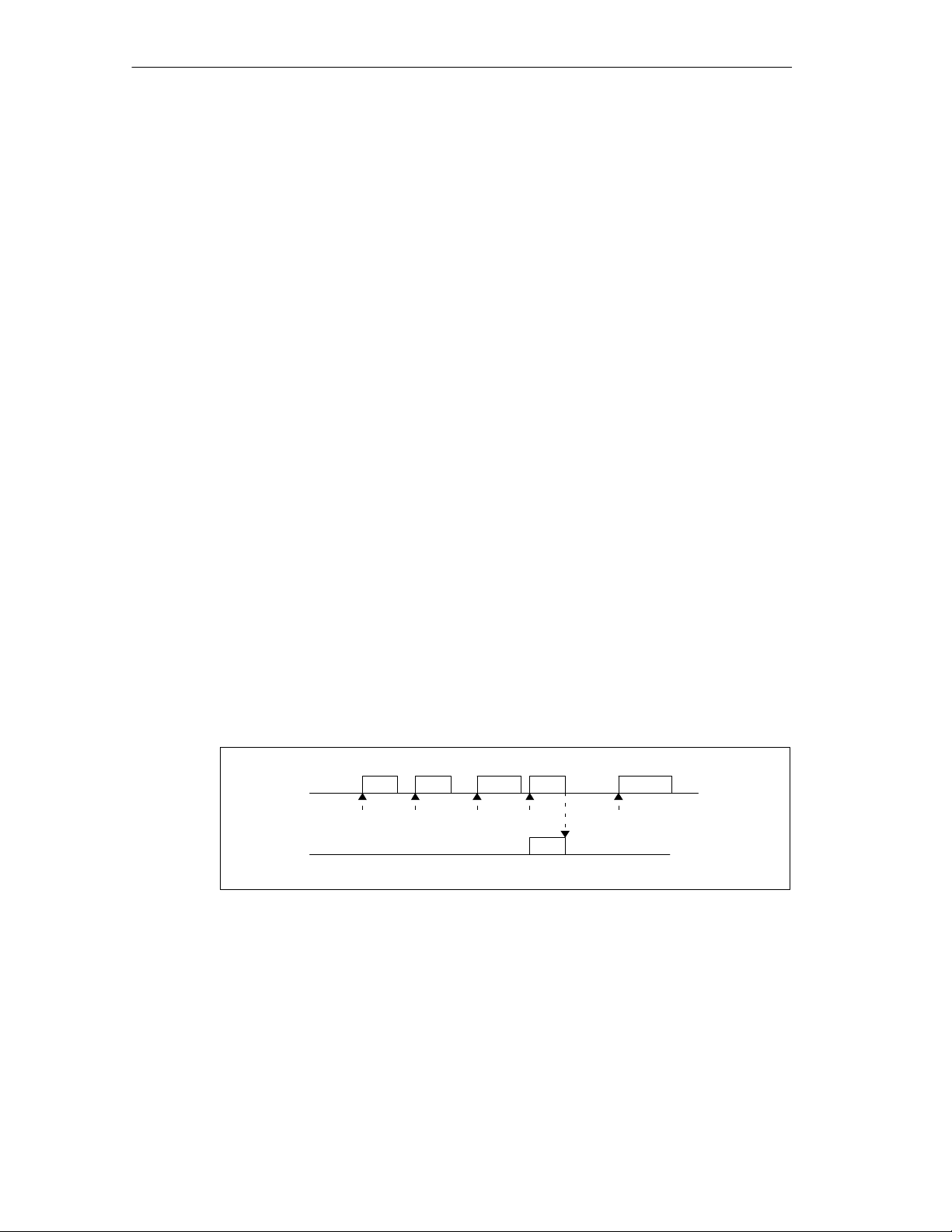
A counter cam track counts the status changes of the track results on this track.
You must specify a value for the counter and start the counter function.
Each rising edge of the track result decrements the counter value of the relevant
track by 1.
As long as the counter value for the counter cam track is higher than 0, the track
flag bit remains 0.
Once the counter value reaches the value 0, the track flag bit is set and, if selected
in the parameter settings, the track signal is set (see Figure 2-4, page 2-11).
At the next falling edge of the track result (all cams on this track are off), the track
flag bit is cleared again and the counter is reset to the specified value.
Cam
Track 0
4
32 10 3Counter reading
Track flag bit
The maximum counter value set in the machine data is 4
Figure 2-2 Switching a Counter Cam Track
4
2-6
FM 452 Electronic Cam Controller
C79000-G7076-C452-04
Page 21
Brake Cam Track
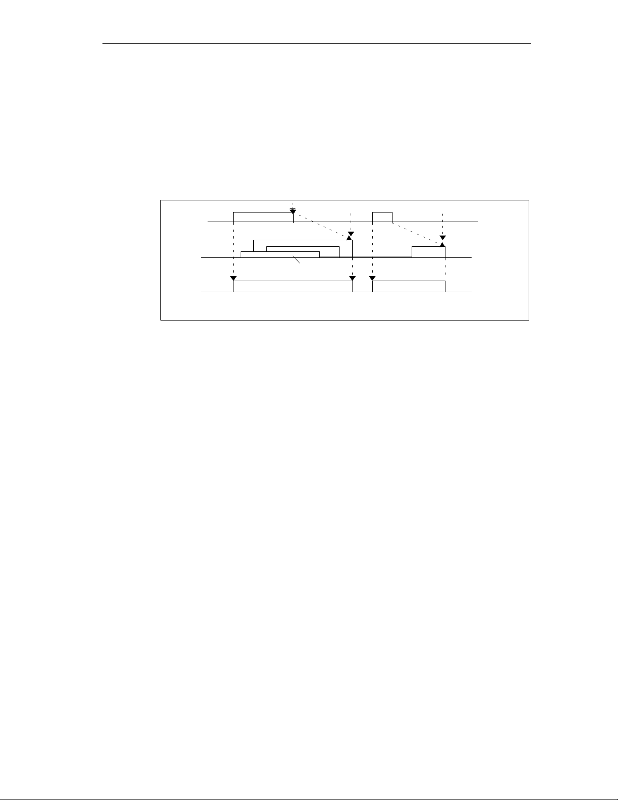
To use track 2 as a brake cam track, digital input I0 must be connected.
A rising signal edge at I0 sets the track flag bit.
The track flag bit is reset again when:
• There is no longer a “1” signal at I0 and afterwards
• the falling edge of the track result of track 2 is detected.
Basics of Cam Control
Brake enable
I0
Cam
Track 2
Track flag bit
1 to 4 indicate 4 cams which influence the brake cam track
Figure 2-3 Response of a Brake Cam Track
1
Braking point
3
2
4
In the example (Figure 2-3), the track flag bit is deactivated by the falling edges of
cams 3 and 4.
FM 452 Electronic Cam Controller
C79000-G7076-C452-04
2-7
Page 22

Basics of Cam Control
2.3 Hysteresis
Definition
Mechanical disturbances on the axis can cause changes in the actual position
value. If the actual position value fluctuates around the edge of a cam or within an
active cam with only one activation direction, this cam would be continuously
activated and deactivated. Hysteresis prevents this switching.
A hysteresis is dependent on the actual value and applies to all cams. It becomes
active as soon as a change of direction is detected. Hysteresis also takes effect
even if no cam is set at the current axis position.
Rules for the Hysteresis Range
The following rules apply to the hysteresis range:
• Hysteresis is always activated when there is a change in direction.
• Within the hysteresis, the indication of the actual value remains constant.
• The direction is not changed within the hysteresis.
• Within the hysteresis, a distance cam is neither activated nor deactivated.
• Within the hysteresis, a time cam is not activated; an active time cam is
deactivated when the set activation time elapses (even within the hysteresis
range).
• After leaving the hysteresis range, the FM 452 determines the following:
– the actual position value,
– The current direction of motion of the axis
– the current states of all cams
• The hysteresis range applies to all cams.
2-8
FM 452 Electronic Cam Controller
C79000-G7076-C452-04
Page 23
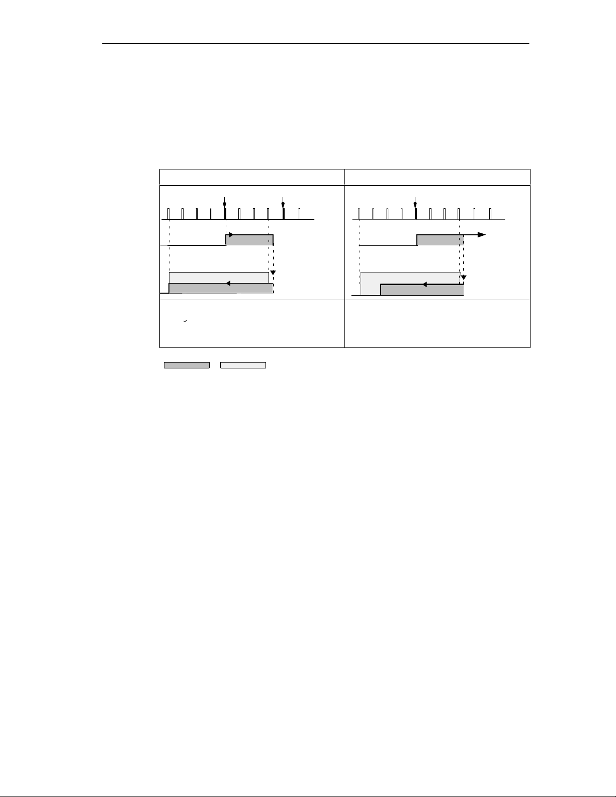
Effects of a Change of Direction on a Cam with Hysteresis
g
The following table illustrates the response of a cam when there is a change of
direction. A distinction must be made between the behavior of a distance cam and
a time cam. The activation direction of the cam is positive.
Table 2-2 Effects of a Change of Direction on a Cam
Basics of Cam Control
Distance cam
CS
23 4567 8
Hysteresis
The hysteresis becomes active after
change of direction is detected.
The cam is deactivated once the
hysteresis range is exited.
Cam Hysteresis
CE
9
1
0
Distance cam
Change
of
direction
Distance cam
Time cam
CS
2345 678
Hysteresis
The cam always remains active for the
selected activation time.
9
1
Time cam
0
Change
of
direction
Time cam
FM 452 Electronic Cam Controller
C79000-G7076-C452-04
2-9
Page 24

Basics of Cam Control
2.4 Dynamic Adjustment
Purpose
The dynamic adjustment is used to compensate delays resulting from the
connected switching elements.
Lead Time
This delay can be specified as a lead time that you specify separately for each
cam. Per cam, you can specify one lead time. The lead time applies to the cam
start and cam end.
Lead Distance
The lead distance of a cam is calculated continuously depending on the current
feedrate and the lead time. The entire cam is displaced by this distance in the
direction of the actual value. The range selected is known as the “static range”, the
range calculated as a result of the lead time is known as the “dynamic range”.
Lead distance lead time · current feedrate of the axis
Calculation of the lead distances of all cams is carried out within ¼ of the longest
selected lead time in the FM 452.
If you set a very large lead time for a cam, you reduce the dynamics of the cam
processing.
2-10
FM 452 Electronic Cam Controller
C79000-G7076-C452-04
Page 25
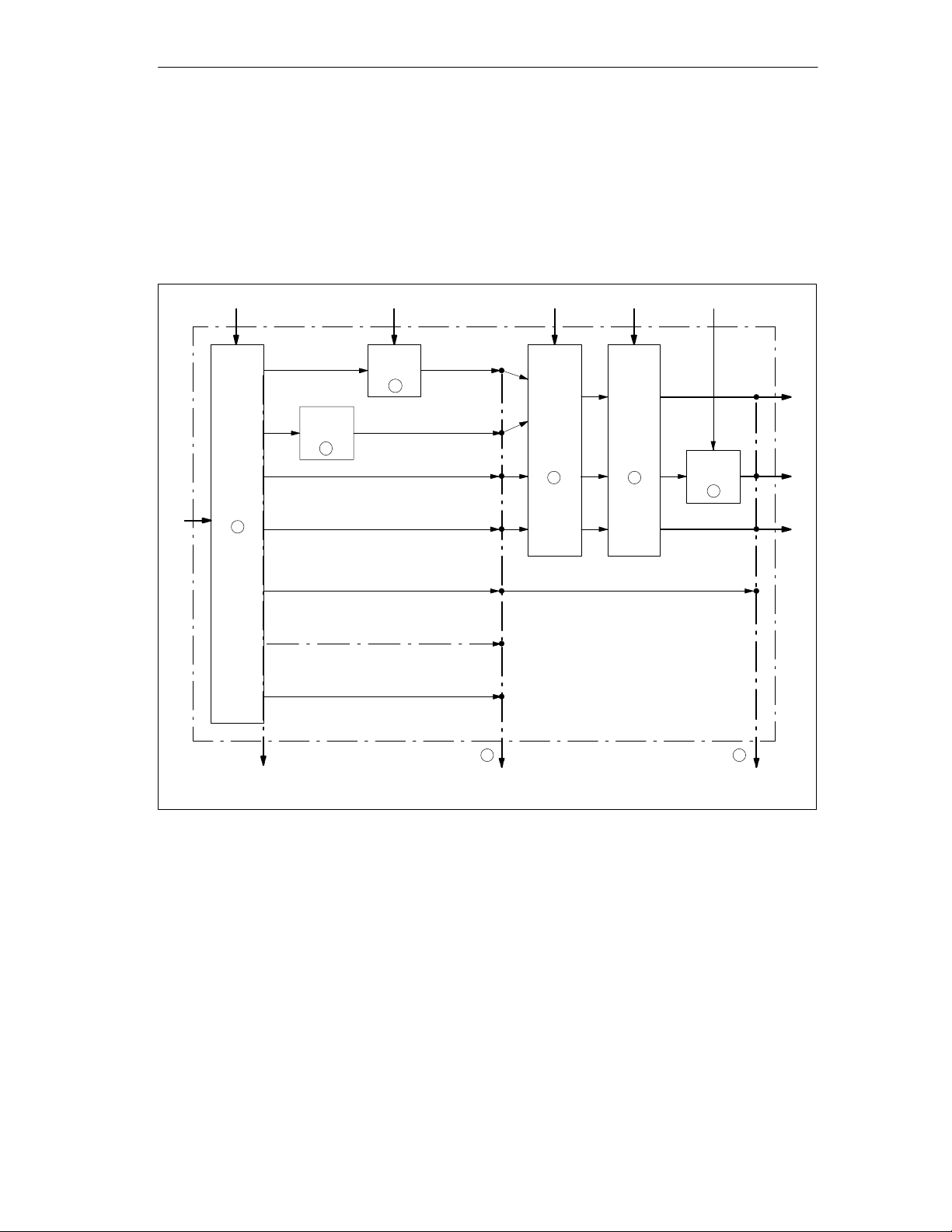
2.5 Interfaces of the Cam Controller
Overview
The schematic below shows the most important interfaces to illustrate the
relationship between data, inputs and outputs.
Basics of Cam Control
Encoder signals
1
Cam Data
I0
Track 2
3
Track
0 to 1
2
Track 3 ... 10
Track 1 1 to 1 5
Track 16 to 31
Actual value, feedrate, direction
Cam flag bits of cam 0 to 127
Machine data Channel DB I3 to I10
Track 3
4 5
Track 10
6
FM 452
Q0 to Q2Q3 to Q10Q11 to Q15
Digital outputs:
Track result
Figure 2-4 Interfaces of the FM 452
FM 452 Electronic Cam Controller
C79000-G7076-C452-04
7 8
Track flag bits, cam flag bits
and data
Track signals
2-11
Page 26

Basics of Cam Control
The schematic is explained in the table below.
No. Description Section
1
When the FM 452 processes the cams, the cam flag bits are calculated from the
switching conditions and the current actual value. The track results based on the
assignment of the cams to the tracks are also calculated.
2
If you have set track 0 or track 1 as a counter cam track, the track result of the cam
controller (point 1) is logically combined with the counter result to produce the track
flag bit. Otherwise, the track flag bit is the same as the track result.
3
If you have set track 2 as a brake cam track, the track result of the cam controller
(point 1) is logically combined with input I0 to produce the track flag bit. Otherwise,
the track flag bit is the same as the track result.
4
Using machine data, you can control whether the previously detected track flag bits
of tracks 0 to 15 of the cam controller are passed on or whether they are set directly
by the track enable (TRACK_EN).
5
You enable the track signals of tracks 0 to 15 with TRACK_EN and the count function
with CNTC0_EN / CNTC1_EN.
6
The track signals of tracks 3 to 10 can be ANDed with digital inputs I3 to I10 if you
have enabled this option in the machine data (EN_IN_I3 to EN_IN_I10).
7
Y ou can read out all the track and cam flag bits at this point (in other words before
they are logically combined with machine and channel data) using the job
ACTPOS_EN or CAMOUT_EN.
For tracks 3 to 31, the track flag bit is the same as the track result (point 1).
After being logically combined with the machine and channel data, the track signals
8
of tracks 0 to 15 are available in the return signals. The track signals of tracks 16 to
31 are identical to the track flag bits of point 7. The track signals of tracks 0 to 15 are
available at digital outputs Q0 to Q15.
2.1
(page 2-2)
2.2.2
(page 2-6)
2.2.2
(page 2-7)
8.7
(page 8-23),
9.15
(page 9-29)
9.11
(page 9-25)
8.7
(Page 8-23)
9.12
(page 9-26)
9.14
(page 9-28)
2-12
FM 452 Electronic Cam Controller
C79000-G7076-C452-04
Page 27

Installing and Removing the FM 452
Important Safety Rules
When integrating an S7-400 with an FM 452 in a plant or system, there are
important rules and regulations that are described in the installation manual
S7-400/M7-400 Programmable Controllers, Hardware and Installation
Selecting Slots
The electronic cam controller FM 452 can be installed in a central or expansion
rack just like a signal module.
Configuring the Mechanical Layout
The options available for the mechanical layout of your system and how to
configure the system are described in the installation manual
S7-400/M7-400 Programmable Controllers, Hardware and Installation
Tools Required for Installation and Removal
3
.
.
To install or remove the FM 452, you require a 4.5 mm screwdriver.
Installing the FM 452 Electronic Cam Controller
1. Hook the FM 452 on at the top and swing it down.
2. Secure the FM 452 with screws (torque approximately 0.8 to 1.1 Nm).
3. Label the FM 452 with its slot number using the number wheel of the rack.
The numbering scheme and numbering of slots is described in the installation
manual
Removing the FM 452 Electronic Cam Controller
1. Switch off the power controller.
2. Release the front connector and remove it.
3. Undo the securing screws on the module.
4. Swing the module upwards and remove it.
S7-400/M7-400 Programmable Controllers, Hardware and Installation
.
FM 452 Electronic Cam Controller
C79000-G7076-C452-04
3-1
Page 28

Installing and Removing the FM 452
3-2
FM 452 Electronic Cam Controller
C79000-G7076-C452-04
Page 29

Wiring the FM 452 Electronic Cam Controller
Chapter Overview
Section Contents Page
4-1 Pinout of the Front Connector 4-2
4.2 Wiring of the Front Connector 4-5
Important Safety Rule
It is essential for the safety of the system to install the elements listed below and to
adapt them to your system.
• EMERGENCY STOP switch with which you can turn off the entire system.
• EMERGENCY STOP limit switches connected directly to the power units of all
drives.
• Motor circuit-breaker.
4
FM 452 Electronic Cam Controller
C79000-G7076-C452-04
4-1
Page 30
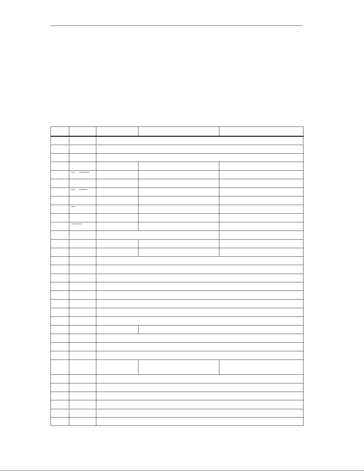
Wiring the FM 452 Electronic Cam Controller
4.1 Pinout of the Front Connector
Front Connector
Connect the encoder, the digital inputs and outputs and the auxiliary power
supplies via the 48-pin front connector.
Pinout of the Front Connector
Pin Name Initiator Incremental Encoder Absolute Encoder
1 --2 --3 1L+ Auxiliary supply 24 V DC
4 A / DA T --- Encoder signal A (5 V) SSI data
5 A / DA T --- Encoder signal A inverse (5 V) SSI data inverse
6 B / CLI 1--- Encoder signal B (5 V) SSI shift clock input
7 B / CLI 1--- Encoder signal B inverse (5 V) SSI shift clock input inverse
8 N --- Zero mark signal (5 V) --9 N --- Zero mark signal inverse (5 V) --10 CLS
11 CLS
12 A* Encoder signal A (24 V) --13 B* --- Encoder signal B (24 V) --14 N* --- Zero mark signal (24 V) --15 Q0 Digital output 0
16 Q1 Digital output 1
17 Q2 Digital output 2
18 Q3 Digital output 3
19 Q4 Digital output 4
20 Q5 Digital output 5
21 Q6 Digital output 6
22 Q7 Digital output 7
23 5.2 V DC --- Encoder supply (5.2 V)
24 24 V DC Encoder supply (24 V)
25 M
26 2L+ Auxiliary supply 24 V DC
27 RE --- Sourcing/sinking (see
28 Q8 Digital output 8
29 Q9 Digital output 9
30 Q10 Digital output 10
31 Q11 Digital output 11
32 Q12 Digital output 12
33 Q13 Digital output 13
2
--- --- SSI shift clock output
2
--- --- SSI shift clock output inverse
3
Encoder ground
---
Appendix B3)
1
1
4-2
FM 452 Electronic Cam Controller
C79000-G7076-C452-04
Page 31

Wiring the FM 452 Electronic Cam Controller
Pin Absolute EncoderIncremental EncoderInitiatorName
34 Q14 Digital output 14
35 Q15 Digital output 15
36 3L+ Auxiliary supply 24 V DC
37 I0 Brake cam track enable
38 I1 Length measurement/ edge detection/ setting actual value on-the-fly
39 I2 Reference point switch
40 I3 Enable track signal 3
41 I4 Enable track signal 4
42 I5 Enable track signal 5
43 I6 Enable track signal 6
44 I7 Enable track signal 7
45 I8 Enable track signal 8
46 I9 Enable track signal 9
47 I10 Enable track signal 10
48 M
1
2
3
3
Listen-in mode
Master mode
Ground connections wired on module
Ground for auxiliary voltages
Auxiliary Supply for Sensors and DA (1L+, 2L+, 3L+)
The 24 V DC auxiliary voltage of the encoders and digital outputs is monitored
• for wirebreak of the 24 V feed line
• for power failure
The 24 V DC auxiliary supply is converted internally to 5 V DC. This means that
24 V DC (terminal 24) and 5.2 V DC (terminal 23) are available on the front
connector for the different types of encoders.
The general technical specifications and requirements of the DC power supplies
are described in the installation manual
Hardware and Installation
.
S7-400/M7-400 Programmable Controllers,
11 Digital Inputs (I0 to I10)
You can connect bounce-free switches (24 V current sourcing) or non-contact
sensors (2 or 3-wire proximity switches) via 11 digital inputs.
The digital inputs are not monitored for short-circuits or wire break and are
connected to module chassis.
A separate LED indicates the state of each input.
FM 452 Electronic Cam Controller
C79000-G7076-C452-04
4-3
Page 32

Wiring the FM 452 Electronic Cam Controller
16 Digital Outputs (Q0 to Q15)
The state (on/off) of tracks 0 to 15 is output via 16 digital outputs. The digital
outputs are connected to module chassis.
The following loads directions are possible:
• Operating voltage 24 V
• Current load 0.5 A/short-circuit proof
A separate LED indicates the state of each output.
4-4
FM 452 Electronic Cam Controller
C79000-G7076-C452-04
Page 33

4.2 Wiring the Front Connector
Connecting Cords
• The cords for digital inputs and digital outputs must be shielded if they exceed
certain lengths, as follows:
– digital inputs: cord length of more than 32 m
– digital ouputs: cord length of more than 100 m
• The encoder cables must be shielded.
• The shields of the encoder cables must make contact with the shield/protective
earth bar and the peripheral connector.
• The cords A, A, B, B and N, N of the incremental encoder must be twisted in
pairs.
• For the connecting cords, use flexible cord, cross-sectional area 0.25 to
1.5 mm
• Ferrules are not necessary. If, however, you prefer to use them, you can use
ferrules without an insulation collar (DIN 46228, form A, short version) and two
cords each with 0.25 to 0.75 mm
2
Wiring the FM 452 Electronic Cam Controller
2
in a ferrule.
Note
If you connect momentary-contact switches or proximity switches, you must use
shielded cords to achieve the optimum noise immunity.
Notes on 24 V DC Wiring
You connect the 24 V DC auxiliary supply for the encoders and digital outputs at
pins 36, 26 and 3.
Remember that all terminals 1L+ to 3L+ must be wired for the module to operate
error-free. You can use up to three power supplies.
Make sure that all the power supplies have a common chassis potential
(see Figure 4-1).
The absence of a voltage is indicated by a diagnostic event.
Caution
!
The module can be damaged.
If you connect the 24 V DC supply incorrectly, the module will be damaged and
must be replaced!
Make sure that the polarity of the 24 V DC supply is correct (auxiliary supplies
1L+, 2L+, 3L+ and chassis M).
FM 452 Electronic Cam Controller
C79000-G7076-C452-04
4-5
Page 34
Wiring the FM 452 Electronic Cam Controller
Ground Connection
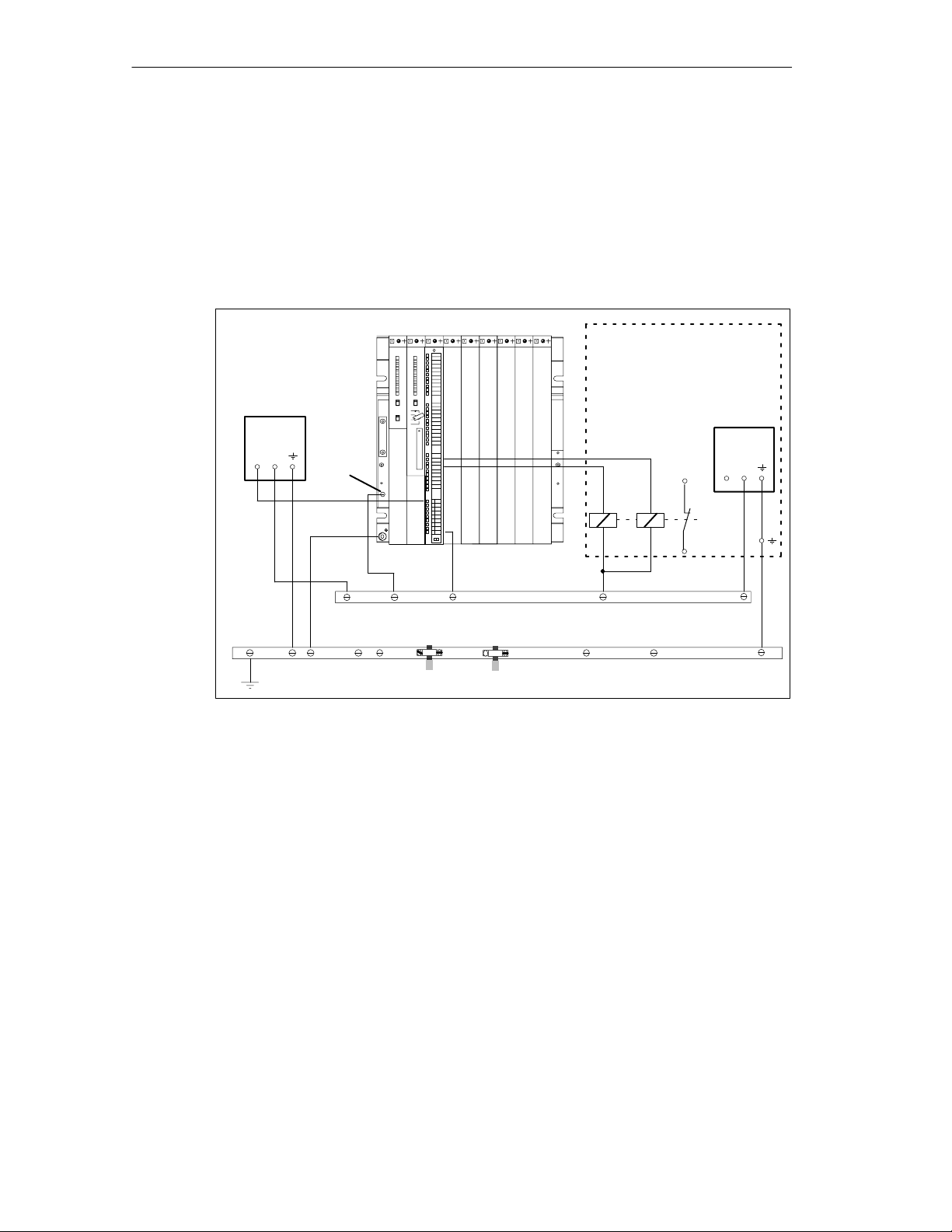
The ground of the auxiliary supplies is electrically connected to the ground of the
CPU; in other words, you must connect pin 48 (M) to the ground of the CPU with
low resistance.
In the case of external encoder supply, you must also establish a low-resistance
connection between the ground of the external encoder supply and the ground of
the CPU.
CPU
PS
FM 452
Auxiliary supply
24 V
+M
M
Power controller
24 V
+M
Figure 4-1 Grounding Diagram
Required Tools
3.5 mm screwdriver or motorized screwdriver
Pin 1L+ ... 3L+
Pin 48 (M for
auxiliary supply)
Ground
Shield/protective earth bar
4-6
FM 452 Electronic Cam Controller
C79000-G7076-C452-04
Page 35

Wiring Procedure
Warning
!
Injury to persons or damage to equipment if the power supply is not turned off.
If you wire the front connector of the FM 452 while it is live, you risk injury from
electric shock.
Wire the FM 452 only when it is not live!
If no emergency stop switch is installed, damage can result from the connected
units.
Install an emergency stop switch with which you can turn off the connected drives
when you are controlling the FM 452 using the
Interface
When wiring the front connector, follow the steps outlined below:
1. Remove the front connector cover.
Wiring the FM 452 Electronic Cam Controller
Parameter Assignment User
.
2. Strip the insulation from the conductors (length 6 mm).
3. Do you want to use wire end ferrules?
If so: Crimp the wire end ferrules onto the conductor.
4. Thread the enclosed strain relief into the front connector.
5. Start wiring from the bottom. When using a front connector with screw
terminals, also screw down unused terminals (tightening torque 0.6 to 0.8 Nm).
6. Secure the cable with the strain relief.
7. Close the front connector.
8. Label the connections on the enclosed labeling strip.
Further Information
A detailed description of wiring a front connector is included in the installation
manual
S7-400/M7-400 Programmable Controllers, Hardware and Installation
.
FM 452 Electronic Cam Controller
C79000-G7076-C452-04
4-7
Page 36

Wiring the FM 452 Electronic Cam Controller
4-8
FM 452 Electronic Cam Controller
C79000-G7076-C452-04
Page 37

Installing the Software
Introduction
5
You make the required settings for the FM 452 using the
User Interface.
FM 352. You will find a description of the
the online help.
Requirements
Before you start to assign parameters for the FM 452 electronic cam controller,
you should check that the following requirements are met:
• STEP 7, Version V4.02 or higher is correctly installed on your programming
Installation
The entire software is on the supplied CD. It is installed as follows:
1. Insert the CD in the drive on your programming device/PC.
2. Start the software installation dialog in Windows 95/Windows NT by clicking the
3. In this dialog, select the CD drive and the folder FMx52\Disk1, then select the
4. Follow the instructions displayed by the installation program.
Parameter Assignment
This user interface is intended for both the FM 452 and the
Parameter Assignment User Interface
device/PC.
”Add/Remove Programs” icon in the ”Control Panel”.
file Setup.exe and start the installation.
Result:The software is installed in the following folders:
in
– SIEMENS\STEP7\S7LIBS\FMx52LIB : FCs and UDTs
– SIEMENS\STEP7\S7FCAM: parameter assignment user interface, readme,
online help
– SIEMENS\STEP7\EXAMPLES\zEn19_01: example
– SIEMENS\STEP7\MANUAL: manual
Note
If you installed STEP 7 in a folder other than SIEMENS\STEP7, this folder is
entered.
Configuration and Parameter Assignment
These topics are described in Chapter 7.
FM 452 Electronic Cam Controller
C79000-G7076-C452-04
5-1
Page 38

Installing the Software
5-2
FM 452 Electronic Cam Controller
C79000-G7076-C452-04
Page 39

Programming the FM 452
Chapter Overview
Section Contents Page
6.1 Basics of Programming an FM 452 6-2
6.2 FC CAM_INIT (FC 0) 6-4
6.3 FC CAM_CTRL (FC 1) 6-5
6.4 FC CAM_DIAG (FC 2) 6-10
6.5 FC CAM_MSRM (FC 3) 6-12
6.6 Data Blocks 6-14
6.7 Interrupts 6-17
6.8 Technical Specifications 6-19
6.9 Fast Access to Module Data 6-21
6.10 Parameter Transfer Routes 6-22
6
FM 452 Electronic Cam Controller
C79000-G7076-C452-04
6-1
Page 40

Programming the FM 452
6.1 Basics of Programming an FM 452
Task
You can assign parameters, control and start up the FM 452 module in a user
program. To exchange data between the user program and module, you use the
functions (FCs) and data blocks (DBs) described below.
Preparations
• Open the block library FMx52LIB in the SIMATIC Manager and copy the
required functions (FCs) and block templates (UDTs) to the block folder of your
project. If the block numbers are already being used, assign new numbers. The
block names are entered unchanged in the symbol table of your S7 program.
– CAM_INIT (FC 0):
This is required to initialize the channel DB following a module startup.
– CAM_CTRL (FC 1):
This is required for data exchange with the module.
– CAM_DIAG (FC 2):
This is required when you process detailed diagnostic information in the
program or want to make this information available to an operator control
and monitoring system.
– CAM_MSRM (FC 3):
This is required when you want to read out the results of a length
measurement or edge detection immediately following a hardware interrupt.
– CAM_CHANTYPE (UDT1):
This is required to generate a channel DB; this is used by FC CAM_INIT,
CAM_CTRL and CAM_MSRM.
– CAM_DIAGTYPE (UDT2):
This is required to generate a diagnostic DB; this is used by FC CAM_DIAG.
– CAM_P016TYPE (UDT3):
This is required to generate a parameter DB with machine data and data for
16 cams; this is used by FC CAM_CTRL to write or read machine or cam
data.
– CAM_P032TYPE (UDT4):
Same as CAM_P016TYPE, however for 32 cams.
– CAM_P064TYPE (UDT5):
Same as CAM_P016TYPE, however for 64 cams.
6-2
– CAM_P128TYPE (UDT6):
Same as CAM_P016TYPE, however for 128 cams.
FM 452 Electronic Cam Controller
C79000-G7076-C452-04
Page 41

Programming the FM 452
• Create data blocks using the UDTs in the block folder of your S7 program. If
you use several modules, you require a separate set of data blocks for each
module.
• Enter the module address in the channel DB and, if used in the diagnostic DB,
also at the address MOD_ADDR. You can also have the address entered
automatically by selecting the module in HW Config and then selecting a data
block in the “Properties” dialog with the “Mod Addr” button.
• If your programming device/PC is connected to a CPU, you can now download
the FCs and DBs to the CPU.
FM 452 Electronic Cam Controller
C79000-G7076-C452-04
6-3
Page 42

Programming the FM 452
6.2 FC CAM_INIT (FC 0)
Task
FC CAM_INIT initializes the following data in the channel DB:
• The control signals
• The return signals
• The trigger, done, error bits of the jobs
• The function switches and their done and error bits
• The job management and the internal buffers for FC CAM_CTRL and FC
CAM_MSRM
Call
The function must be run through following a startup (power supply on) on the
module or CPU. You should therefore install it, for example in the warm restart OB
(OB100) and the remove/insert OB (OB83) or call it in the initialization phase of
your user program. This ensures that your user program does not access old data
following a CPU restart or a module startup.
Call Parameters
Name Data Type I/O Meaning
DB_NO INT I Number of the Channel DB
Return values
This function does not return a value.
6-4
FM 452 Electronic Cam Controller
C79000-G7076-C452-04
Page 43

6.3 FC CAM_CTRL (FC 1)
Tasks
With FC CAM_CTRL, you can read the operating data from the module, initialize
the module, and control it during operation. For these tasks, you use the control
signals, return signals and write and read jobs.
Each time it is called, the function performs the following activities:
• Read return signals:
FC CAM_CTRL reads all return signals from the module and enters them in the
channel DB. Since the control signals and jobs are only executed following this,
the return signals reflect the status of the module before the block was called.
• Write control signals:
The control signals entered in the channel DB are transferred to the module.
The enabling of the cam processing is, however, delayed as long as the trigger
for a “set reference point” or “write cam data” job is set. The activation (or
reactivation) of cam processing is delayed for this time.
• Execute job:
The next job is executed based on the trigger bits for jobs entered in the
channel DB.
Programming the FM 452
Call
Data Used
This function must be called cyclically.
Before you call the function, enter all the data in the channel DB that are required
to execute the intended functions.
• Channel DB:
The module address must be entered in the channel DB.
• Parameter DB:
If you want to write or read machine or cam data using jobs, you require a
parameter DB whose number must be entered in the channel DB. The size of
the parameter DB must be adequate for the number of cams.
FM 452 Electronic Cam Controller
C79000-G7076-C452-04
6-5
Page 44

Programming the FM 452
Jobs
Data exchange with the module other than the control and return signals is handled
using jobs.
To start a job, you set the corresponding trigger bit in the channel DB and provide
the relevant data for write jobs. You then call FC CAM_CTRL to execute the job.
A read job is executed immediately. Due to the required confirmations from the
module, a write job requires at least three calls (or OB cycles).
You can send several jobs at the same time, if necessary, along with control
signals. Apart from the job for writing the function switch, the jobs are executed in
the order of the trigger bits as specified in the channel DB. Once a job has been
completed, the trigger bit is reset. The next time the block is called, the next job is
located and executed.
For each job there is not only a trigger bit but also a done bit and an error bit. In
their names, instead of the ending _EN (for “enable“), they have the ending _D (for
“done“) or _ERR (for “error”). Done and error bits of the job should be set to 0 after
they have been evaluated or before the job is started.
If you set the JOBRESET bit, all the done and error bits are reset before the
pending jobs are processed. The JOBRESET bit is then set to 0 again.
Function Switches
The function switches activate and deactivate module states. A job for writing the
function switches is only executed when there is a change in a switch setting. It is
always executed between the jobs “set reference point” (REFPT_EN) and “set
actual value” (AVAL_EN). The setting of the function switch is latched after the job
has been executed.
Length measurements and edge detection must not be activated at the same time.
FC CAM_CTRL makes sure that when one of the function switches is activated,
the other is deactivated. If you do switch both function switches at the same time
(0 –> 1), the length measurement is activated.
Function switches and jobs can be used at the same time in one FC CAM_CTRL
call.
As with the jobs, there are done bits with the ending _D and error bits with the
ending _ERR for the function switches.
To be able to evaluate the done and error bits, you should set these bits to 0 when
you change a function switch.
Startup
6-6
When the module or CPU starts up, call FC CAM_INIT (see Section 6.2,
Page 6-4). Among other things, the function switches are reset.
FC CAM_CTRL acknowledges the module startup. During this time, RET_VAL and
JOBBUSY are set to 1.
FM 452 Electronic Cam Controller
C79000-G7076-C452-04
Page 45

Call Parameters
Name Data Type I/O Meaning
DB_NO INT I Number of the channel DB
RET_VAL INT O Return value
Return Values
The function provides the following return values:
RET_VAL BR Description
1 1 At least one job active
0 1 No job active, no error
-1 0 Error:
Programming the FM 452
Data error (DAT_ERR) or
Communication error (JOB_ERR) occurred
FM 452 Electronic Cam Controller
C79000-G7076-C452-04
6-7
Page 46

Programming the FM 452
Job Status
You can check the status of job execution using the return value RET_VAL and the
JOBBUSY activity bit in the channel DB. You can evaluate the status of a single
job based on the trigger, done, and error bits of the job.
• Job active:
– RET_VAL = 1
– JOBBUSY = 1
– Trigger bit = 1
– Done bit = 0
– Error bit = 0
• Job completed without error:
– RET_VAL = 0
– JOBBUSY = 0
– Trigger bit = 0
– Done bit = 1
– Error bit = 0
• Job completed with error in this job:
– RET_VAL = –1
– JOBBUSY = 0
– Trigger bit = 0
– Done bit = 1
– Error bit = 1
• Write job aborted:
– RET_VAL = –1
– JOBBUSY = 0
– Trigger bit = 0
– Done bit = 0
– Error bit = 1
6-8
FM 452 Electronic Cam Controller
C79000-G7076-C452-04
Page 47

Response to Errors
If bad data were written by a write job, the module returns the message
DATA_ERR = 1. If an error occurs in communication with the module during a write
or read job, the cause of the error is entered in the JOB_ERR parameter in the
channel DB.
• Error in a write job:
If an error occurs in a job, the trigger bit is reset and the error bit (_ERR) and
the done bit (_D) are set. The trigger bit is reset and the error bit (_ERR) is set
for all write jobs still pending.
The pending read jobs continue to be processed. JOB_ERR is set again for
each job.
• Error in a read job:
If an error occurs in a job, the trigger bit is reset and the error bit (_ERR) and
the done bit (_D) are set.
The read jobs still pending continue to be processed. JOB_ERR is set again for
each job.
Programming the FM 452
For more detailed information on the errors, refer to the parameters JOB_ERR and
DATA_ERR (see Chapter 11, Diagnostics and Appendix C.3, Page C-12)
FM 452 Electronic Cam Controller
C79000-G7076-C452-04
6-9
Page 48

Programming the FM 452
6.4 FC CAM_DIAG (FC 2)
Tasks
Using FC CAM_DIAG, you read out the diagnostic buffer of the module and can
make it available for display in an operator control and monitoring system or for
programmed evaluation.
Call
This function must be called cyclically. A further call in an interrupt OB is not
permitted. For complete execution of this function, at least two calls (cycles) are
required.
The function reads the diagnostic buffer when a new entry is indicated in the
diagnostic buffer by the return signal DIAG = 1. After reading the diagnostic buffer,
DIAG is set to 0 by the module.
Data Used
• Diagnostic DB:
The module address must be entered in the diagnostic DB. The latest entry in
the diagnostic buffer is entered in the DIAG[1] structure and the oldest entry in
the DIAG[4] structure.
Jobs
You can read the diagnostic buffer whether or not there is a new entry by setting
the DIAGRD_EN trigger bit. After reading the diagnostic buffer, the trigger bit is set
to 0.
Startup
There is no startup processing associated with the function.
Call Parameters
Name Data Type I/O Meaning
DB_NO INT I Number of the diagnostic DB
RET_VAL INT O Return value
6-10
FM 452 Electronic Cam Controller
C79000-G7076-C452-04
Page 49
Return Values
The function provides the following return values:
RET_VAL BR Description
1 1 Job active
0 1 No job active, no error
–1 0 Error:
Response to Errors
If an error occurs in a job, the cause of the error can be found in the diagnostic DB
in the JOB_ERR parameter (see Chapter 11, Diagnostics and Appendix C.3,
Page C-12).
Programming the FM 452
FM 452 Electronic Cam Controller
C79000-G7076-C452-04
6-11
Page 50

Programming the FM 452
6.5 FC CAM_MSRM (FC 3)
Tasks
You use FC CAM_MSRM when you want to evaluate the measurement data of
length measurements or edge detection immediately in the hardware interrupt OB.
Call
The function is called in a hardware interrupt OB (for example OB 40).
Data Used
The module address must be entered in the channel DB.
Startup
There is no startup processing associated with the function.
Call Parameters
Name Data Type I/O Meaning
DB_NO INT I Number of the Channel DB
RET_VAL INT O Return value
Return Values
The function provides the following return values:
RET_VAL BR Description
1 1 Job active
0 1 No job active, no error
–1 0 Error:
6-12
FM 452 Electronic Cam Controller
C79000-G7076-C452-04
Page 51
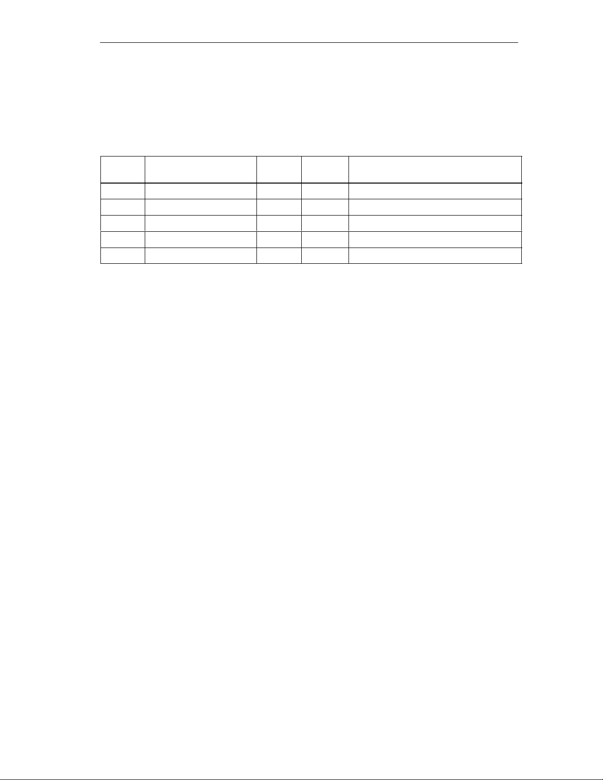
Measurement Results and Status Information
The measurement results and status information are entered in the channel DB:
Table 6-1 Interrupt Measured Data in the Channel DB
Programming the FM 452
Address
112.0 BEG_VAL DINT L#0 Initial Value
1 16.0 END_VAL DINT L#0 End value
120.0 LEN_VAL DINT L#0 Length
56.0 JOB_ERR_M INT 0 Communication error
58.0 JOBBUSY_M BOOL FALSE Job active
Name Type Initial
Value
Comment
Response to Errors
If an error occurs in a job, the cause of the error can be found in the channel DB in
the JOB_ERR_M parameter (see Chapter 11, Diagnostics and Appendix C.3,
Page C-12).
FM 452 Electronic Cam Controller
C79000-G7076-C452-04
6-13
Page 52

Programming the FM 452
6.6 Data Blocks
6.6.1 Templates for Data Blocks
The supplied library (FMx52LIB) contains a block template (UDT) for each data
block. Based on this UDT, you can create data blocks with any numbers and
names.
Optimizing the UDT
To save memory, you can delete unused data areas at the end of the
UDT CAM_CHANTYPE. You can then save the modified UDT under a different
name.
You can then generate a channel DB based on this UDT that is optimized for your
application.
Functions that access deleted data areas can no longer be used.
The supplied UDTs for the machine and cam data are matched already to the
possible numbers of cams. They can be optimized in steps of 16 cams.
6.6.2 Channel DB
Task
The channel DB is the data interface between the user program and the
FM 452 electronic cam controller. All the data required for controlling and operating
the module is entered in this data block.
Structure
The channel DB is subdivided into various areas:
Address *)/version switch
Control signals
Return signals
Function switches
Trigger bits for write jobs
Trigger bits for read jobs
Done bits
Error bits
Job management for functions
Data for jobs
Channel DB
*) The address can be entered
in the parameter assignment interface.
6-14
FM 452 Electronic Cam Controller
C79000-G7076-C452-04
Page 53

6.6.3 Diagnostic DB
Task
The diagnostic DB provides the data storage for FC CAM_DIAG and contains the
diagnostic buffer of the module created by this function.
Structure
Diagnostic DB
Module address
Internal data
Job status
Trigger bit
Diagnostic buffer
Programming the FM 452
6.6.4 Parameter DB
Task
The machine and cam data are stored in the parameter DB. The parameters can
be modified by the user program or by an operator control and monitoring system.
The modified data can be imported into the parameter assignment user interface
and displayed there. You can export the data displayed in the parameter
assignment user interface to a parameter DB.
There can be several sets of parameter assignment data for a module (for
example, for various recipes) that you can activate program-controlled.
Structure
Parameter DB
CAM_P016TYPE (UDT3)
Machine data
Cam data of cams 0 to 15
CAM_P032TYPE (UDT4)
Machine data
Cam data of cams 0 to 31
CAM_P064TYPE (UDT5)
Machine data
Cam data of cams 0 to 63
CAM_P0128TYPE (UDT6)
Machine data
Cam data of cams 0 to 127
FM 452 Electronic Cam Controller
C79000-G7076-C452-04
6-15
Page 54

Programming the FM 452
6.7 Interrupts
Interrupt Handling
The FM 452 can trigger hardware interrupts and diagnostic interrupts. You service
these interrupts in an interrupt OB. If an interrupt is triggered and the
corresponding OB is not loaded, the CPU changes to STOP (refer to the manual
Programming with STEP
You can enable interrupt servicing at the following levels:
1. Enabling general interrupts for the entire module:
– Select the module in HW Config
– Using the menu command Edit > Object Properties > Basic Parameters,
enable diagnostic and/or hardware interrupts.
– Select the OB number for the hardware interrupt using Edit > Object
Properties > Addresses.
– Save and compile the hardware configuration.
7).
– Download the hardware configuration to the CPU.
2. Enabling events for hardware interrupts in the machine data.
3. Setting parameters for hardware interrupts in the cam data for cams 0 to 7.
Evaluation of a Hardware Interrupt
If a hardware interrupt is triggered by the FM 452, the following information is
available in the variable OB40_POINT_ADDR (or in the corresponding variable of
a different hardware interrupt OB):
Table 6-2 Contents of the Double Word OB40_POINT_ADDR
Byte
0 0 0 0 0 0 0 0 0
1 0 0 Start of
2 Cam 7onCam 7
3 Cam 3onCam 3
You can see the cause of the interrupt in Byte 1:
Bit 7 Bit 6 Bit 5 Bit 4 Bit 3 Bit 2 Bit 1 Bit 0
off
off
0 0 Cam End of
meas.
Cam 6onCam 6
off
Cam 2onCam 2
off
Cam 5onCam 5
off
Cam 1onCam 1
off
0
meas.
Cam 4onCam 4
off
Cam 0onCam 0
off
6-16
• Cam:
Evaluate byte 2 and byte 3 according to the table.
• Measurement start/measurement end:
Using the CAM_MSRM function, you can read the current measured values
from the module.
FM 452 Electronic Cam Controller
C79000-G7076-C452-04
Page 55

Lost Hardware Interrupts
If the processing of a hardware interrupt is not yet completed in the hardware
interrupt OB, the module registers all subsequent hardware interrupt events. If an
event occurs again before the hardware interrupt could be triggered, the module
triggers the “hardware interrupt lost” diagnostic interrupt.
Evaluating a Diagnostic Interrupt
Following a diagnostic interrupt, the diagnostic information is available in the local
data of OB82 and can be used for fast analysis. Call the CAM_DIAG function to
find out the exact cause of the problem as entered in the diagnostic buffer.
The local data of the diagnostic interrupt OB that are supported are listed below.
Programming the FM 452
Variable Data
Description
Type
OB82_MDL_DEFECT BOOL Module fault
OB82_INT_FAULT BOOL Internal error
OB82_EXT_FAULT BOOL External error
OB82_PNT_INFO BOOL Channel error
OB82_EXT_VOLTAGE BOOL External auxiliary voltage missing
OB82_FLD_CONNCTR BOOL No front connector
OB82_WTCH_DOG_F BOOL Watchdog monitoring has responded
OB82_INT_PS_FLT BOOL Internal module power supply failed
OB82_HW_INTR_FLT BOOL Hardware interrupt lost
FM 452 Electronic Cam Controller
C79000-G7076-C452-04
6-17
Page 56
Programming the FM 452
Á
Á
Á
Á
Á
Á
Á
Á
6.8 Technical Specifications
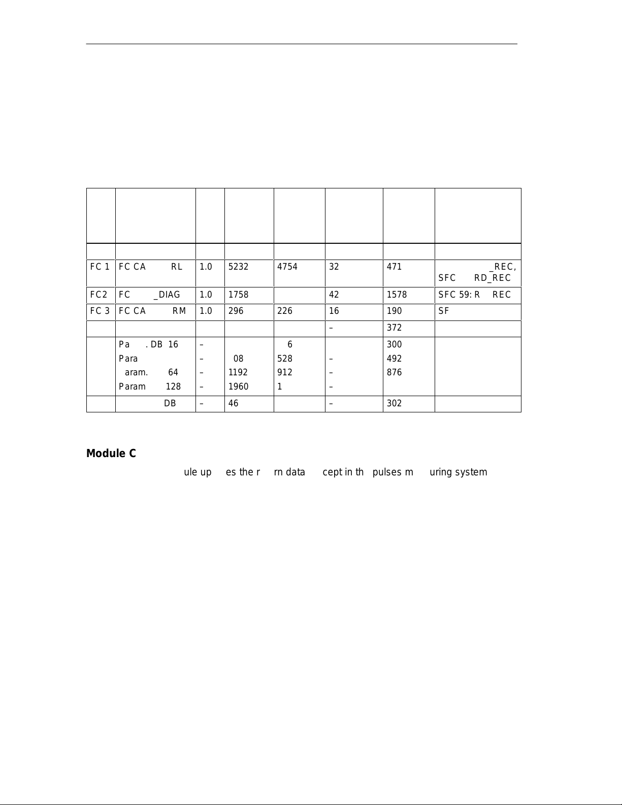
The following table provides an overview of the technical specifications of the
functions.
Table 6-3 Technical Specifications for the FM 452 Technological Functions
No. Block Name VersionSpace
Occupied
in Load
Memory
(bytes)
Space
Occupied
in Main
Memory
(bytes)
Space
Occupied in
Local Data
Area
(bytes)
FC0 FC CAM_INIT 1.0 192 138 2 102
FC 1
FC CAM_CTRL
Á
FC2
FC CAM_DIAG
FC 3
FC CAM_MSRM
ÁÁÁÁ
1.0
1.0
1.0
Á
5232
ÁÁ
1758
296
4754
ÁÁ
1614
226
32
ÁÁÁ
42
16
Channel DB – 986 804 – 372
Param. DB 16
Param. DB 32
Param. DB 64
Param. DB 128
–
616
–
808
–
1192
–
1960
336
528
912
1680
–
–
–
–
Diagnostic DB – 460 338 – 302
Module Cycle
The module updates the return data (except in the pulses measuring system)
every 4 ms.
MC7
Code/Data
(bytes)
4718
ÁÁ
1578
190
300
492
876
1644
Called
System Functions
SFC 58: WR_REC,
SFC 59: RD_REC
ÁÁÁÁ
SFC 59: RD_REC
SFC 59: RD_REC
6-18
In the pulses measuring system, the data for the actual position value and the
track signals are available after 0.5 ms.
FM 452 Electronic Cam Controller
C79000-G7076-C452-04
Page 57
Execution Times
Á
Á
Á
Á
Á
Á
Á
Á
Á
Á
Á
Á
Á
Á
Á
Á
Á
Á
Á
Á
Á
Á
Á
Á
Á
Á
Á
Á
Á
Á
Á
Á
Á
Á
Á
Á
Á
Á
Á
Á
Á
Á
Á
Á
Á
Á
Á
Á
Á
Á
Á
Á
Á
Á
Á
Á
Á
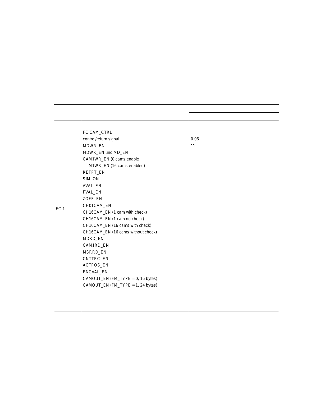
The following table provides you with an overview of the execution times of the
functions for the FM 452. The run time from the first block call to the done
message (trigger bit is reset) is shown. The cycle is extended by between 1 and
2 ms when a function is called.
Table 6-4 Execution Times of the Functions for the FM 452
Programming the FM 452
Block Block Name/Job
FC 0 FC CAM_INIT 0.01
FC CAM_CTRL
ÁÁ
ÁÁ
ÁÁ
ÁÁ
ÁÁ
ÁÁ
ÁÁ
ÁÁ
ÁÁ
FC 1
ÁÁ
ÁÁ
ÁÁ
ÁÁ
ÁÁ
ÁÁ
ÁÁ
ÁÁ
ÁÁ
ÁÁ
FC 2
FC 3 FC CAM_MSRM 0.5
FM 452 Electronic Cam Controller
C79000-G7076-C452-04
БББББББББББББ
control/return signal
MDWR_EN
БББББББББББББ
MDWR_EN und MD_EN
БББББББББББББ
CAM1WR_EN (0 cams enabled)
БББББББББББББ
CAM1WR_EN (16 cams enabled)
БББББББББББББ
REFPT_EN
SIM_ON
БББББББББББББ
AVAL_EN
БББББББББББББ
FVAL_EN
БББББББББББББ
ZOFF_EN
БББББББББББББ
CH01CAM_EN
БББББББББББББ
CH16CAM_EN (1 cam with check)
CH16CAM_EN (1 cam no check)
БББББББББББББ
CH16CAM_EN (16 cams with check)
БББББББББББББ
CH16CAM_EN (16 cams without check)
БББББББББББББ
MDRD_EN
БББББББББББББ
CAM1RD_EN
MSRRD_EN
БББББББББББББ
CNTTRC_EN
БББББББББББББ
ACTPOS_EN
БББББББББББББ
ENCVAL_EN
БББББББББББББ
CAMOUT_EN (FM_TYPE = 0, 16 bytes)
БББББББББББББ
CAMOUT_EN (FM_TYPE = 1, 24 bytes)
FC CAM_DIAG
Idle run
Read diagnostic buffer
ББББББББББ
ББББББББББ
ББББББББББ
ББББББББББ
ББББББББББ
ББББББББББ
ББББББББББ
ББББББББББ
ББББББББББ
ББББББББББ
ББББББББББ
ББББББББББ
ББББББББББ
ББББББББББ
ББББББББББ
ББББББББББ
ББББББББББ
ББББББББББ
ББББББББББ
CPU 416-2 (6ES7 416-2XK01-0AB0)
Execution Time in ms
0.06
11.8
15.6
3.1
5.4
2.2
2.3
2.3
2.3
2.3
2.3
2.3
2.3
9.2
8.5
1.6
2.1
1.0
1.0
1.0
1.0
1.1
1.1
0.02
1.9
6-19
Page 58
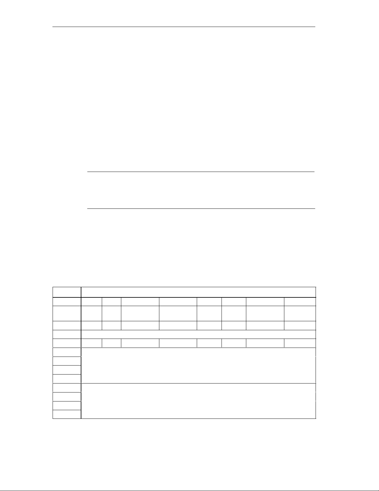
Programming the FM 452
6.9 Fast Access to Module Data
Application
In special applications or in an interrupt level, particularly fast access to return and
control signals is necessary. You can obtain this data directly via the input and
output areas of the module.
To coordinate startup following each module startup (for example after inserting the
module, CPU STOP → RUN), FC CAM_CTRL must be called continuously until
the end of the startup is indicated by RET_VAL = 0.
Note
If you access data on the FM 452 directly, you must only use the non-internal data
described here using the method described here. Otherwise, your user program
will encounter difficulties accessing the module.
Direct Access for Reading Return Signals
The byte addresses are specified relative to the output address of the module. The
names of the bits correspond to the names in the channel DB.
In STL, you access the data with the commands PIB (read 1 byte) and PID (read
4 bytes).
Address Bit Number
7 6 5 4 3 2 1 0
Byte 0 PARA internalinternal DATA_ERR internal DIAG internal internal
Byte 1 0 0 0 CAM_ACT 0 0 0 0
Byte 2 internal
Byte 3 0 0 FVAL_DONE HYS GO_P GO_M MSR_DONE SYNC
Byte 4
Byte 5
Byte 6
Byte 7
Byte 8
Byte 9
Byte 10
Byte 11
ACT_POS
TRACK_OUT
6-20
FM 452 Electronic Cam Controller
C79000-G7076-C452-04
Page 59
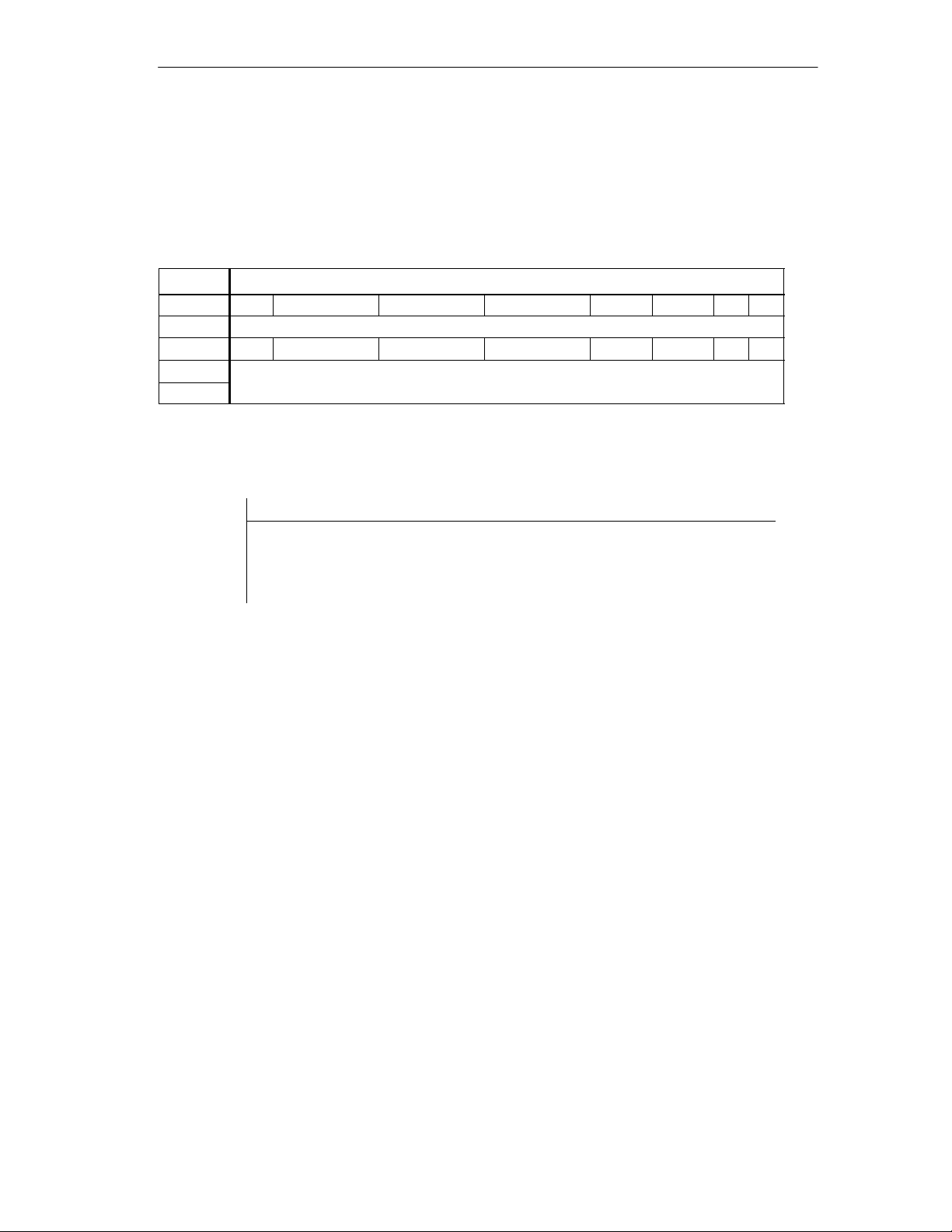
Programming the FM 452
Direct Access for Writing Control Signals
The byte addresses are specified relative to the input address of the module. The
names of the bits correspond to the names in the channel DB.
In STL, you access the data with the commands PQB (write 1 byte) and PQW
(write 2 bytes).
Address Bit number
7 6 5 4 3 2 1 0
Byte 0 internal
Byte 1 0 CNTC1_EN CNTC0_EN CAM_EN DIR_P DIR_M 0 0
Byte 2
Byte 3
TRACK_EN
Example: Actual Position Value (ACT_POS)
STL Explanation
Example
L PID 516
The base address of the module is 512
Read the current actual position value
(ACT_POS) with direct access:
Base address of the module + 4
FM 452 Electronic Cam Controller
C79000-G7076-C452-04
6-21
Page 60
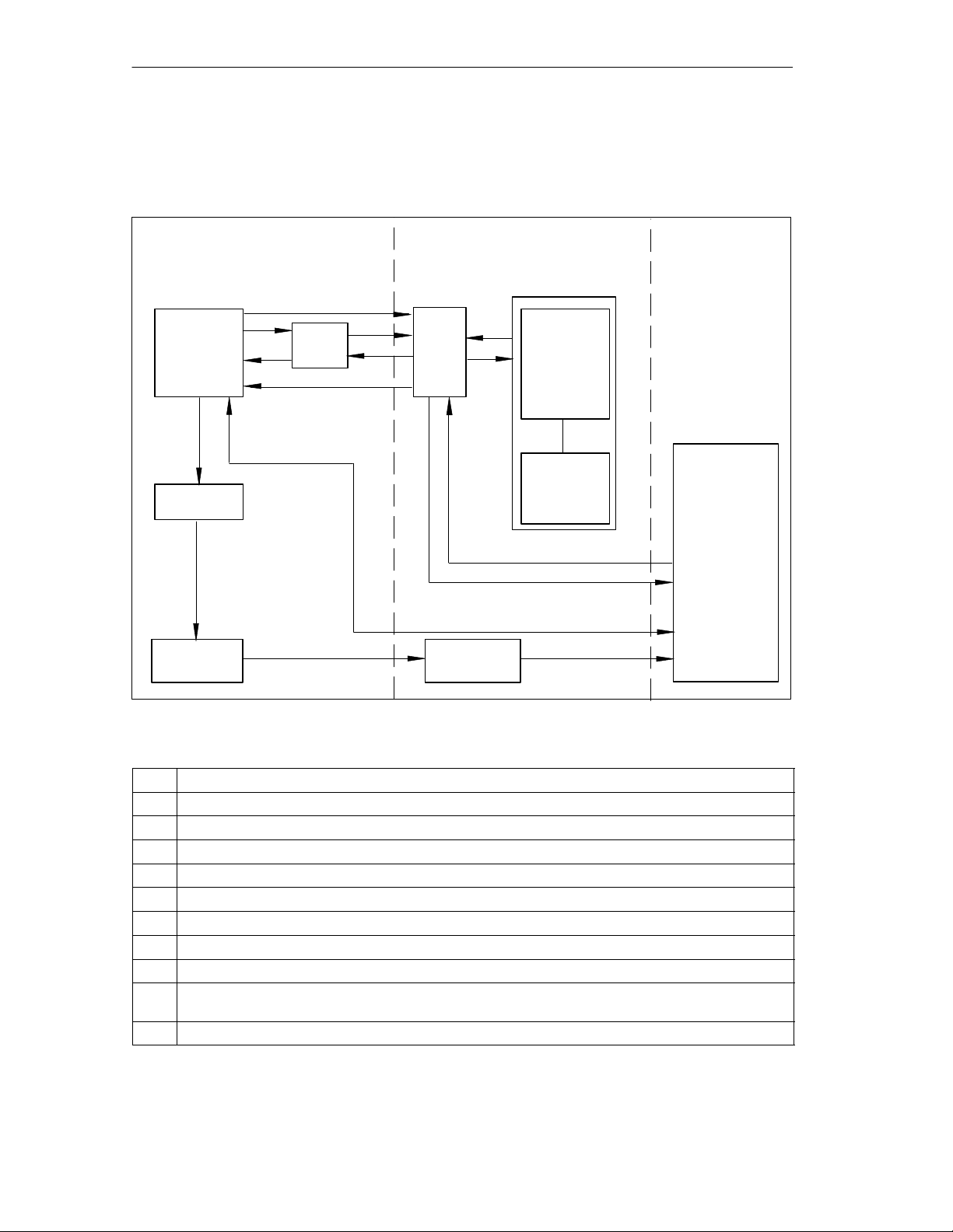
Programming the FM 452
6.10 Parameter Transfer Routes
The term parameter includes the following machine and cam data.
PG/PC
offline
Para. ass.
user interface
1
HW Config
2
System data
(SDB)
Download
10
11
Upload to PG
4
Download
DB
2a
10b
10a
11a
11b
DB
6
7
System data
(SDB)
CPU
online
8
9
FM 452
User
program
CAM_CTRL
Parameters
(machine and
cam data)
5
3
Figure 6-1 Parameter Transfer Routes
1 Save parameters in the parameter assignment user interface.
2 Save HW configuration, compile, and download to CPU.
3 The CPU writes the parameters to the module during system parameter assignment.
4 Upload the parameters of the module to the PG with the “Upload” command.
5 Download parameters from FM Config to the module with the “Download” command.
6 Write parameters to the module using jobs in the user program.
7 Read parameters from the module using jobs in the user program.
8 Store parameters from the user program in the online DB.
9 Read parameters into the user program from the online DB.
10 Export parameters from the parameter assignment user interface to the DB (offline or online DB);
an offline DB must then also be downloaded to the CPU.
11 Import parameters from an online or offline DB into the parameter assignment user interface.
6-22
FM 452 Electronic Cam Controller
C79000-G7076-C452-04
Page 61

Programming the FM 452
Typical Situations for the Transfer of Parameters:
1 You edit the parameters with the parameter assignment user interface. The module
must then be assigned the parameters automatically during startup.
Action required: steps 1, 2, 3
2 You modify parameters during startup in the test mode in the parameter
assignment user interface:
Action required: steps 4, 5
3 You set the parameters with the parameter assignment user interface. When it
starts up, the module should be assigned parameters only by the user program
using data blocks:
Action required: steps 10, 6
4 You set the parameters with the parameter assignment user interface. These
should be available to the user program for temporary modifications.
Action required: steps 1, 2, 3 for automatic parameter assignment.
Action required: steps 10, 7 for access by the user program.
5 You modify parameters (exclusively) using the user program:
Action required: steps 7, 9, 8, 6
6 You want to see the data modified by the user program in the parameter
assignment user interface.
Action required: step 11
7 You want to create data for recipes:
Action required: step 10
8 The parameters modified during installation should be downloaded automatically
during startup:
Action required: steps 1, 2, 3
9 The parameters modified by the user program should be downloaded automatically
during startup:
Action required: steps 6, 11, 1, 2, 3
FM 452 Electronic Cam Controller
C79000-G7076-C452-04
6-23
Page 62

Programming the FM 452
6-24
FM 452 Electronic Cam Controller
C79000-G7076-C452-04
Page 63

Putting the FM 452 into Operation
Important Note
Please read the points in the following warning carefully.
Warning
!
To prevent injury to personnel and damage to equipment, please note the
following points:
• Install an EMERGENCY STOP switch in the vicinity of the computer. This is
the only way to ensure that the system can be switched off safely in the event
of a computer or software failure.
• Install an EMERGENCY STOP limit switch directly connected to the power
units of all drives.
• Make sure that nobody can obtain access to the area of the system that
contains moving parts.
• When controlling and monitoring the FM 452 at the same time in both your
program and in the Test Startup dialog, conflicts can arise whose effects are
unpredictable. For this reason, always switch the CPU to STOP when you work
in the Test dialog or deactivate your program.
7
FM 452 Electronic Cam Controller
C79000-G7076-C452-04
7-1
Page 64

Putting the FM 452 into Operation
Hardware Installation and Wiring
In the first section, you will install the FM 452 in your S7-400 and wire up the front
connector.
Step What Needs to Be Done?
1 Install the FM 452 (see Chapter 3)
Insert the module in one of the slots available.
2 Wire the FM 452 (see chapter 4)
Wire the front connector of the FM 452:
• Digital inputs
• Digital outputs
• Encoder connection
• Power supply to the FM 452
3 Check the limit switches relevant for safety
Check that the following are functioning correctly:
• The limit switches
• The emergency stop circuits
4 Front connector
The front connector must sit firmly.
5 Check the shielding of each individual cable.
6 Turn on the power supply
Switch the CPU to STOP (safe state).
Turn on the 24 V supply for the FM 452.
Creating a Project
Now set up a project in
The steps required to set up a project in the SIMATIC Manager are described
below (without using a wizard).
Step What Needs to Be Done?
1 If you have not already done so, install the parameter assignment software.
2 Create a new project in the SIMATIC Manager (File > New).
3 Insert a station in your project (Insert > Station).
4 Select the station and start the configuration user interface “HW Config” by
double-clicking “Hardware”.
5 Insert a rack in your hardware configuration with the following:
STEP 7
.
• A power supply (PS)
• CPU
• Function module (FM)
6 Save this hardware configuration in HW Config (Station > Save).
7-2
FM 452 Electronic Cam Controller
C79000-G7076-C452-04
Page 65

Putting the FM 452 into Operation
Assigning Parameters with the Parameter Assignment User Interface.
If you are putting the module into operation for the first time, assign the parameters
for the module using the parameter assignment software. Keep to the sequence
below:
Step What Needs to Be Done?
1 Select the row in the rack containing the FM 452 module.
2 Now double-click to start the parameter assignment user interface for the FM 452.
3 Using the menu command File > Properties, you can modify the following settings:
• General
You can modify the name and enter a comment.
• Addresses
You can modify the base address and assign the address area to a part process
image. (Note down the module address displayed.)
• Basic Parameters
You can set the interrupt type and the reaction to a CPU stop.
4 In the block diagram displayed, you can select the dialogs for Axis, Encoders, Cams,
Tracks and Interrupt Enable and set the required parameters.
5 Save the parameter settings with the menu command File > Save
6 Close the parameter assignment user interface with File > Exit.
7 Save the hardware configuration in HW Config with Station > Save and Compile.
8 Set up an online connection to the CPU and download the hardware configuration to the
CPU. At each change from STOP to RUN, this data is transferred to the FM 452.
9 Select Test > Startup.
Test and Startup
You can now test the entries and modifications you have made.
Step What Needs to Be Done?
1 Check your data with the dialogs Test > Startup, Test > Service and Test > Error
Evaluation.
2 You can modify incorrect machine data in the Test > Startup dialog. These
modifications remain valid until the next STOP-RUN change on the CPU.
3 You can save the corrected machine data on the CPU by repeating steps 7 to 9 of the
previous table.
Tests for Axis Synchronization and Switching Behavior
Using the following tests you can check the correct assignment of parameters for
the FM 452.
FM 452 Electronic Cam Controller
C79000-G7076-C452-04
7-3
Page 66

Putting the FM 452 into Operation
Step What Needs to Be Done?
1 Synchronize the axis
• Incremental encoders
– Select “set reference point”. Enter
the required value (see
Section 9.4).
or
– Set the function switch “retrigger
reference point” (see Section 9.8).
Check the actual status of the axis. The actual position must agree with the position
indicated.
2 Check the switching behavior of the cams and tracks being used.
• Absolute encoders
– The FM 452 is synchronized
immediately after parameter
assignment.
– Make an absolute encoder
adjustment (see Section 8.4)
You may first have to calculate the
exact value with “set reference
point”.
• Activate the test enable.
• Run “set reference point”.
• Activate cam processing.
• Enable the track signals.
• Rotate the encoder or
• Set the simulation function switch.
3 Test the other settings according to your application
• Set reference point
• Set actual value
7-4
FM 452 Electronic Cam Controller
C79000-G7076-C452-04
Page 67
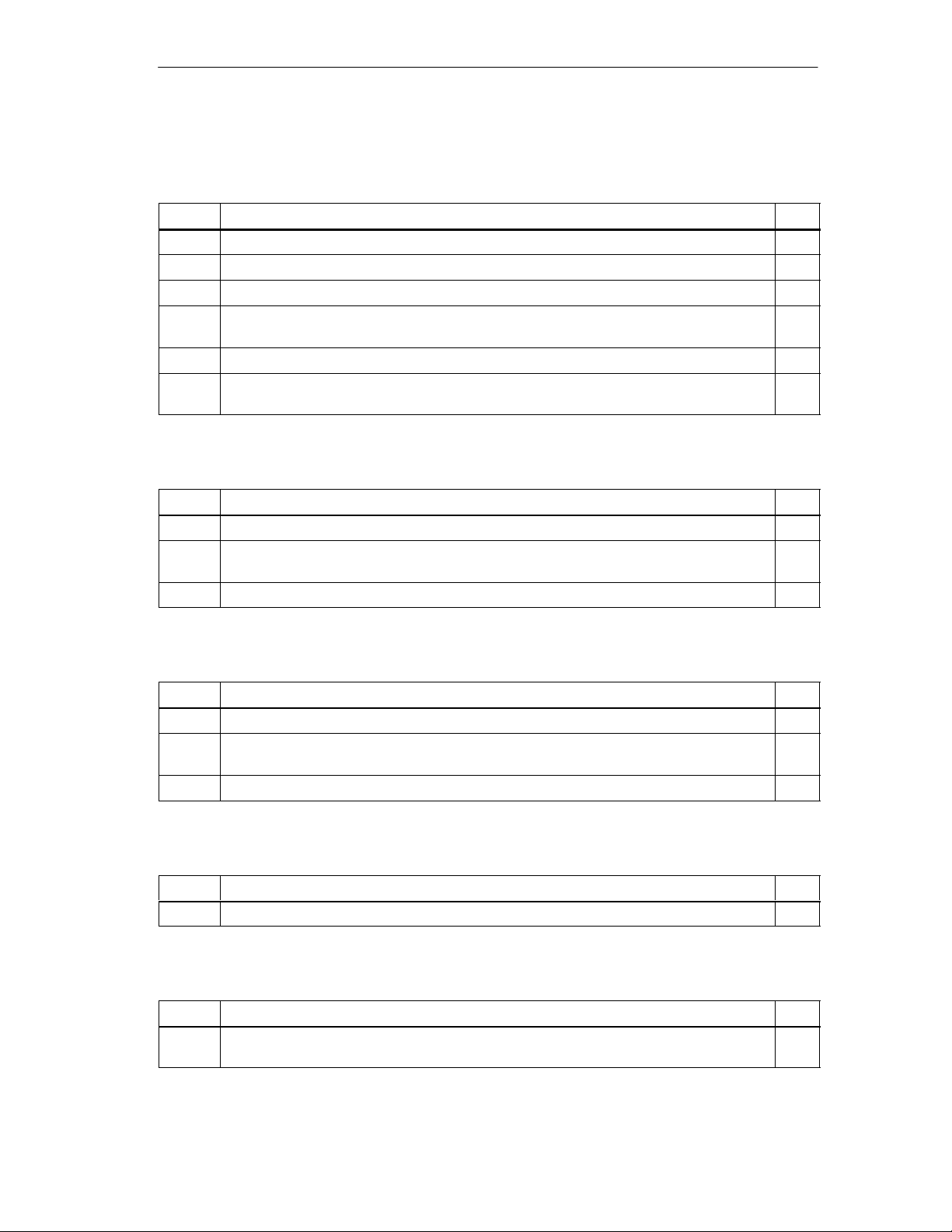
Putting the FM 452 into Operation
Preparations for Programming
You still need to create the blocks required in your project.
Step What Needs to Be Done?
1 Select the library FMX52LIB in the SIMATIC Manager (File > Open > Libraries).
2 Copy the functions FC0, FC1 and the channel DB template UDT1 to your blocks folder.
3 Create a channel DB based on the UDT1 template for each module.
4 If you want to use a programmed diagnostic evaluation, copy FC2 and UDT2 and create
a diagnostic DB for each module.
5 If you require length measurement or edge detection with hardware interrupt, copy FC3.
6 If you want to write and read machine data in the user program, you require UDT3 for
16 cams, UDT4 for 32 cams, UDT5 for 64 cams, or UDT6 for 128 cams.
Preparing the Channel DB
Step What Needs to Be Done?
1 Open the channel DB.
2 Check whether the module address has already been entered in the
MOD_ADDR parameter. If it is not there, it must be entered now.
3 Save the channel DB (File > Save).
Preparing the Diagnostic DB
Step What Needs to Be Done?
1 Open the diagnostic DB
2 Check whether the module address has already been entered in the
MOD_ADDR parameter. If it is not there, it must be entered now.
3 Save the diagnostic DB (File > Save).
Linking the Functions
Step What Needs to Be Done?
1 Link the required functions in your user program.
Downloading the Blocks to the CPU
Step What Needs to Be Done?
1 Select the blocks in the SIMA TIC Manager and download them with PLC > Download
to CPU.
FM 452 Electronic Cam Controller
C79000-G7076-C452-04
7-5
Page 68

Putting the FM 452 into Operation
7-6
FM 452 Electronic Cam Controller
C79000-G7076-C452-04
Page 69

Machine Data and Cam Data
Chapter Overview
Section Contents Page
8.1 Writing and Reading the Machine and Cam Data 8-2
8.2 System of Units 8-6
8.3 Machine Data of the Axis 8-7
8.4 Absolute Encoder Adjustment 8-12
8.5 Machine Data for the Encoder 8-15
8.6 Resolution 8-20
8.7 Number of Cams and Track Data 8-23
8.8 Interrupt Enable 8-25
8.9 Cam Data 8-26
8
FM 452 Electronic Cam Controller
C79000-G7076-C452-04
8-1
Page 70

Machine Data and Cam Data
8.1 Writing and Reading the Machine and Cam Data
This chapter is relevant if you want to write the parameters directly to the module
using instructions in the user program without using the parameter assignment
user interface.
All the machine and cam data are stored in the parameter DB. You must enter the
number of the parameter DB in the appropriate channel DB.
You can write the parameter DB while working in the parameter assignment user
interface with “Export” and read it with “Import”.
Writing and Activating Machine Data
With the machine data, you adapt the FM 452 to the axis and the encoder.
The machine data are in the parameter DB at addresses 3.1 to 104.0.
Initial Parameter Assignment
If the module does not yet contain machine data (return signal PARA = 0), follow
the steps outlined below to set initial parameters without the parameter assignment
user interface:
• Enter the new values in the parameter DB.
• Download the parameter DB to the CPU.
• Set the following trigger bit in the channel DB:
– Write machine data (MDWR_EN)
• Call the FC CAM_CTRL function in the cyclic user program.
Changing Machine Data
To change existing machine data (return signal PARA = 1) from the user program,
follow the steps below:
• Enter the new values in the parameter DB.
• Set the trigger bits in the channel DB:
– Write machine data (MDWR_EN)
– Activate machine data (MD_EN)
• Call the FC CAM_CTRL function in the cyclic user program.
• Check whether the previous cam data are compatible with the modified
machine data.
• Always write the cam data of the set cams again whether they have been
changed or not (CAM1WR_EN...CAM8WR_EN)
8-2
FM 452 Electronic Cam Controller
C79000-G7076-C452-04
Page 71

Machine Data and Cam Data
Note
If parameters that are relevant for synchronization were modified, the
synchronization is deleted when the machine data are activated. The settings are
also reset and all the machine and cam data are deleted on the module.
Parameters relevant for synchronization are as follows:
• Axis type
• End of rotary axis
• Encoder type
• Travel per encoder revolution
• Increments per encoder revolution
• Number of revolutions (with SSI encoders)
• Reference point coordinate
• Absolute encoder adjustment (with SSI encoders)
• Type of reference point retriggering (with incremental encoders or initiators)
• Direction adaptation
• Number of Cams
• Software limit switch start and end (with linear axes)
Reading Machine Data
To read the current machine data from the module, follow the steps outlined below:
• Set the following trigger bit in the channel DB:
– Read machine data (MDRD_EN)
• Call the FC CAM_CTRL function in the cyclic user program.
This enters the current machine data in the parameter DB on the CPU.
Excerpt from the Channel DB
Address Name Type Initial
Value
35.0 MDWR_EN BOOL FALSE 1 = Write machine data
35.1 MD_EN BOOL FALSE 1 = Activate machine data
37.1 MDRD_EN BOOL FALSE 1 = Read machine data
Comment
FM 452 Electronic Cam Controller
C79000-G7076-C452-04
8-3
Page 72

Machine Data and Cam Data
Writing Cam Data
With the cam data, you specify the type and action of the cams and their
assignment to the tracks.
Cam data are located in the parameter DB from address 108.0 onwards. They are
grouped in packages each with 16 cams.
Cam data are active immediately after writing.
To write cam data without the parameter assignment user interface, follow the
steps outlined below:
• Enter the new values in the parameter DB.
• Download the parameter DB to the CPU.
• Set the trigger bits in the channel DB (CAM1WR_EN...CAM8WR_EN)
• Call the FC CAM_CTRL function in the cyclic user program.
Reading Cam Data
To read the current cam data from the module, follow the steps outlined below:
• Set the following trigger bit in the channel DB:
– Read cam data (CAM1RD_EN ... CAM8RD_EN)
• Call the FC CAM_CTRL function in the cyclic user program.
This writes the current cam data to the parameter DB on the CPU.
Excerpt from the Channel DB
Address Name Type Initial
Value
35.3 CAM1WR_EN BOOL FALSE 1 = Write cam data 1 (cams 0 to 15)
35.4 CAM2WR_EN BOOL FALSE 1 = Write cam data 2 (cams 16 to 31)
35.5 CAM3WR_EN BOOL FALSE 1 = Write cam data 3 (cams 32 to 47)
35.6 CAM4WR_EN BOOL FALSE 1 = Write cam data 4 (cams 48 to 63)
35.7 CAM5WR_EN BOOL FALSE 1 = Write cam data 5 (cams 64 to 79)
36.0 CAM6WR_EN BOOL FALSE 1 = Write cam data 6 (cams 80 to 95)
36.1 CAM7WR_EN BOOL FALSE 1 = Write cam data 7 (cams 96 to 111)
36.2 CAM8WR_EN BOOL FALSE 1 = Write cam data 8 (cams 112 to 127)
37.2 CAM1RD_EN BOOL FALSE 1 = Read cam data 1 (cams 0 to 15)
37.3 CAM2RD_EN BOOL FALSE 1 = Read cam data 2 (cams 16 to 31)
37.4 CAM3RD_EN BOOL FALSE 1 = Read cam data 3 (cams 32 to 47)
37.5 CAM4RD_EN BOOL FALSE 1 = Read cam data 4 (cams 48 to 63)
37.6 CAM5RD_EN BOOL FALSE 1 = Read cam data 5 (cams 64 to 79)
37.7 CAM6RD_EN BOOL FALSE 1 = Read cam data 6 (cams 80 to 95)
Comment
8-4
FM 452 Electronic Cam Controller
C79000-G7076-C452-04
Page 73

Machine Data and Cam Data
Address CommentInitial
38.0 CAM7RD_EN BOOL FALSE 1 = Read cam data 7 (cams 96 to 111)
38.1 CAM8RD_EN BOOL FALSE 1 = Read cam data 8 (cams 112 to 127)
TypeName
Value
Order when Writing Machine and Cam Data
Always modify machine and cam data in the following order:
• Write machine data
• Activate machine data
• Write cam data
If you set the trigger bits for these jobs all at once, FC CAM_CTRL makes sure
that the jobs are processed in the correct order.
FM 452 Electronic Cam Controller
C79000-G7076-C452-04
8-5
Page 74

Machine Data and Cam Data
8.2 System of Units
Selecting a unit
In the parameter assignment user interface of the cam controller, you can select a
specific unit for inputting and outputting data (default: mm).
You can also select the following units:
• Millimeters, inches, degrees and pulses.
Note
If you change the unit in the parameter assignment user interface, the values are
calculated in the new system. This can lead to rounding errors.
If you change the unit using the machine data, the values are not recalculated
automatically.
If the unit is changed from or to “pulses”, the cam processing is deactivated and
the axis is no longer synchronized.
Units in the Parameter DB
Address Name Type Initial
Value
8.0 UNITS DINT L#1 Units
1 = 10
2 = 10
3 = 10-4 degrees
4 = 10-2 degrees
5 = pulses
6 = 10-3 degrees
Standard Units
In this manual, limit values are always specified in the unit mm. To define the
limits in other systems of units, please make the following calculation:
To convert.... Calculate...
mm inches Limit value (inches) = limit value (mm) 0.1
mm deg 10-4 (4 decimal places)
10-3 (3 decimal places)
-2
10
(2 decimal places)
mm pulses Limit value (pulses) = limit value (mm) 1000
Comment
-3
mm
-4
inches
Limit value (degrees) = limit value (mm) 0.1
Limit value (degrees) = limit value (mm) 1
Limit value (degrees) = limit value (mm) 10
8-6
FM 452 Electronic Cam Controller
C79000-G7076-C452-04
Page 75
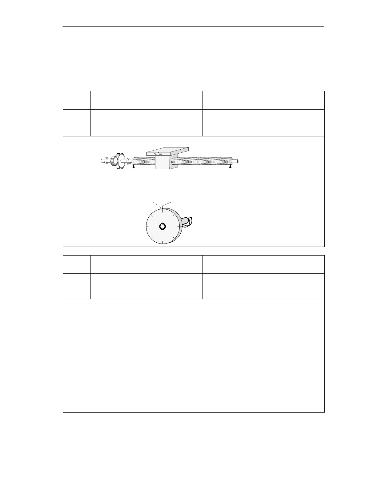
8.3 Machine Data of the Axis
Axis Data
Machine Data and Cam Data
Address Name Type Initial
Value
12.0 AXIS_TYPE DINT L#0 Axis type:
0 = Linear axis
1 = Rotary axis
A linear axis is an axis with a limited physical travel range.
Physical start Physical end
A rotary axis is an axis whose travel range is not restricted by mechanical limit stops.
Highest displayed
value
Address Name Type Initial
Start of rotary axis = end of rotary axis
Value
Comment
Comment
16.0 ENDROTAX DINT L#100000 End of rotary axis:
Range:
1 m to +1 000 000 000 m
The value “end of rotary axis” is the highest theoretical value that the actual value can reach.
The highest theoretical value is however never displayed since it is physically the same position as the
start of the rotary axis (0).
The highest value that can be displayed by a rotary axis is as follows:
End of the rotary axis [m] – resolution [m / pulse]1 [pulse]
Example: End of rotary axis 1000 mm
The display jumps:
• With a positive direction of rotation from 999 mm to 0 mm.
• With a negative direction of rotation from 0 mm to 999 mm.
Rotary axis with absolute encoders
With a rotary axis with an absolute encoder the rotary axis range (0 to end of rotary axis) must exactly
cover the total number of encoder steps of the absolute encoder.
Rotary axis end[m] number of revolutions (encoder) ·
steps(encoder)[pul]
revolution
·RES
m
pul
FM 452 Electronic Cam Controller
C79000-G7076-C452-04
8-7
Page 76

Machine Data and Cam Data
Address Name Type Initial
Value
44.0 REFPT DINT L#0 Reference point coordinate:
Range: – 1 000 000 000 m to
Incremental encoder and initiator:
Using the “Retrigger Reference Point” function switch and a synchronization event specified by the “Type
of Reference Point Retriggering”, the reference point coordinate is assigned to this event.
Absolute encoder (SSI)
An axis with an absolute encoder is always synchronized provided no error is detected (after transfer of the
first error-free SSI frame).
Read the description of absolute encoder adjustment in Section 8.4 (Page 8-12), explaining the
interaction of absolute encoder adjustment with other data.
Linear axis
The value of the reference point coordinate must be within the working range (including the start
software limit switch and end software limit switch).
Rotary axis
The value of the reference point coordinate must be greater than or equal to 0 and must be less than the
value “end of rotary axis” “ (0 ≤ reference point coordinate < “end of rotary axis”).
Address Name Type Initial
Value
52.0 RETR_TYPE DINT L#0 Type of reference point retriggering:
Ranges:
0 = Ref. point switch and zero marker direction +
1 = Ref. point switch and zero marker direction –
6 = Only ref. point switch
7 = Only zero marker
With “type of reference point retriggering”, you specify the conditions for synchronizing the axis when
working with an incremental encoder or an initiator (see also Section 9.8, Page 9-19)
Comment
+ 1 000 000 000 m
Comment
8-8
FM 452 Electronic Cam Controller
C79000-G7076-C452-04
Page 77
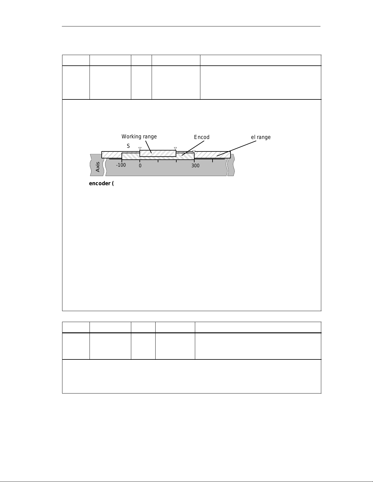
Machine Data and Cam Data
Address Name Type Initial Value Comment
64.0
68.0
SSW_STRT
SSW_END
DINT
DINT
L# –100 000 000
L# 100 000 000
Start software limit switch
End software limit switch
Range:
– 1 000 000 000 m to 1 000 000 000 m
This axis data is only of significance with a linear axis.
The software limit switches are active when the FM 452 is synchronized. The range set by the software
end limit switch is known as the working range. The limits of the working range can be monitored by the
FM 452.
The start software limit switch (SLS) must always be less than the end software limit switch (SLE).
Working range
Encoder range Travel range
SLS SLE
-100
0 300
Axis
Absolute encoder (SSI)
The FM 452 is synchronized after it has received a complete error-free frame. The software limit switches
are monitored from this point in time.
The absolute encoder which you use must at least cover the working range (from software limit switch
start to software limit switch end).
Incremental encoder and initiator
After starting up the FM 452, the axis is initially not synchronized. The software limit switches are only
monitored after synchronization.
Relationship: working range, encoder range, travel range
• The “working range” is the range you specify for your task using the software limit switches.
• The “encoder range” is the range covered by the encoder. With a linear axis, this is placed
symmetrically over the working range by the module; in other words, the module shifts the encoder
range so that the distances between the software limit switches and the ends of the encoder range
are the same (see figure).
• The “travel range” is the range of values that can be processed by the FM 452. It is dependent on the
resolution.
The following rule applies:
Travel range ≥ encoder range ≥ working range
Address Name Type Initial Value Comment
80.0 HYS DINT L#0 Hysteresis:
Ranges:
0...65 535 [pul] resolution [
The range of values depends on the resolution:
The maximum value that can be input is as follows:
– For linear axes: maximum input value < ¼ of the working range
– For rotary axes: maximum input value < ¼ of the rotary axis range
FM 452 Electronic Cam Controller
C79000-G7076-C452-04
m
/
]
pul
8-9
Page 78
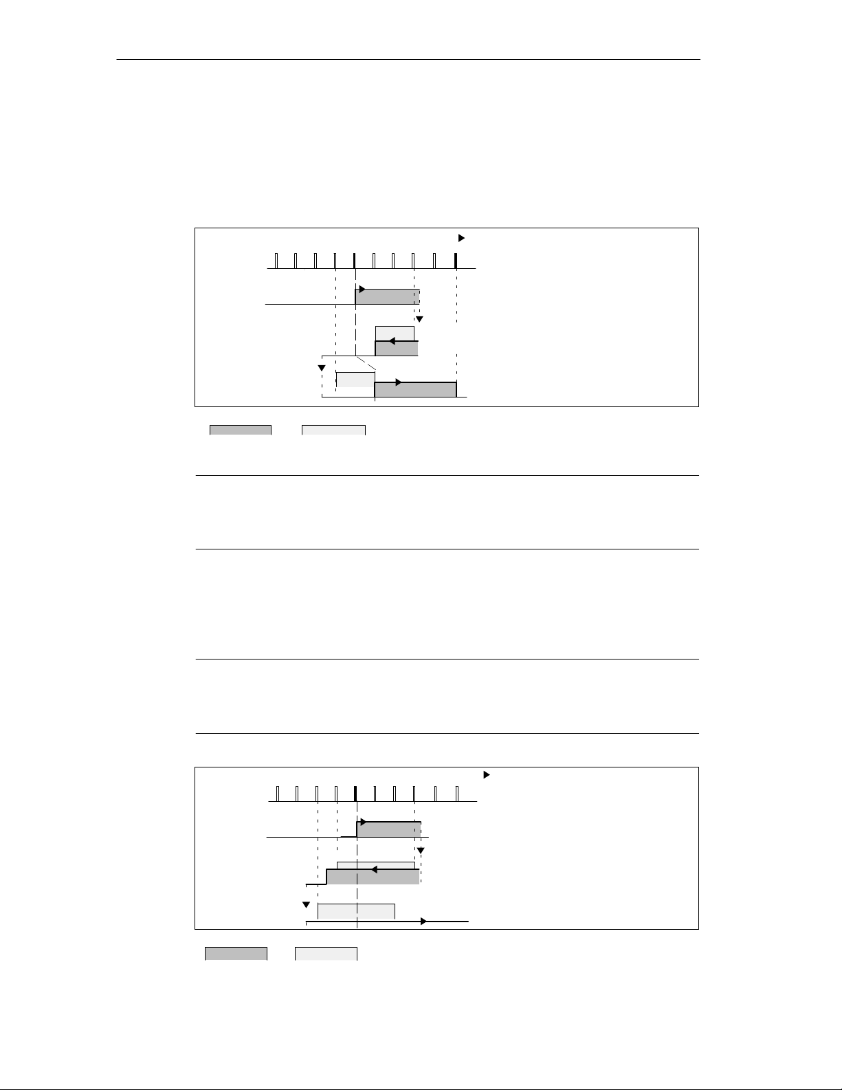
Machine Data and Cam Data
Distance Cams and Hysteresis
A distance cam is activated in the following situation:
• the detected actual value is within the distance cam and
• no hysteresis is active.
The position of the switching point depends on where the direction changes.
23 45 67 8
Change of
direction
4)
Activation direction
CS
1)
3)
5)
9
2)
Change of
direction
CE
1
0
1)
Cam is activated since the cam
start is reached in the positive
activation direction
2)
Cam remains active despite
new direction due to hysteresis
3)
Cam is deactivated at the end
of the hysteresis
4)
Cam remains deactivated after
the change in direction
5)
Cam is activated again at the
end of the hysteresis
Cam
Figure 8-1 Activation of a Distance Cam with Hysteresis
Note
Distance cams that are shorter than the hysteresis can be hidden by the
hysteresis when there is a change in direction.
Time Cams with Hysteresis
A time cam is activated in the following situation:
• the cam start is reached in the activation direction and
• no hysteresis is active.
Note
If the range between the reversal point and the start of the time cam is less than
the hysteresis, the time cam will be “hidden” by the hysteresis.
Figure 8-2 illustrates a time cam that is not activated again.
23 45 67 8
Change of
direction
Cam Hysteresis
3)
Hysteresis
2)
CS
Activation direction
1)
9
1
0
Change of
direction
1)
Cam is activated since the cam
start is passed in the
positive activation direction
2)
After the change in direction,
the cam remains active until the
on time has expired regardless
of the hysteresis
3)
Cam start is hidden by the
hysteresis, the cam is not
activated
8-10
Figure 8-2 Activation of a Time Cam with Hysteresis
FM 452 Electronic Cam Controller
C79000-G7076-C452-04
Page 79
Machine Data and Cam Data
Address Name Type Initial
Comment
Value
84.0 SIM_SPD DINT L#0 Simulation Speed
The simulation speed depends on the
resolution.
0 = stationary
8
5⋅ 10
= Highest possible setting of the
module
Within this range, the simulation speed
depends on the resolution:
1000 resolution ≤ simulation speed ≤ 3 10
resolution
This machine data specifies the simulation speed for simulation (see Chapter 9). The actual simulation
speed V
following formula:
can deviate from the entered simulation speed V
sim
7
610
V
=
sim
integer
RES
7
610
V
RES
sim,V
)
(
and is calculated according to the
sim, V
In this formula
• V
• V
: Simulation speed set by the FM 452, unit:
sim
: Simulation speed specified in the machine data, unit:
sim,V
• RES: Resolution calculated from the encoder data, unit:
m
/
.
min
m
/
.
min
m
/
pulse
• Integer (): from this expression, only the value before the decimal point is used for further
calculation. This expression must be within the range 2 ... 65536 for all calculations.
As a result of the relationships (see formula), the actual simulation speed changes abruptly.
7
Address Name Type Initial
Comment
Value
4.0 EDGEDIST DINT L#0 Minimum Edge-to-Edge Distance
Range:
0 ... 1 000 000 000 m
With this machine data, you define a range after detection of the start of measurement when using edge
detection. If the end of the measurement is within this range, the measurement is rejected.
The start of the measurement is signaled only after the minimum edge-to-edge distance has been
traveled.
FM 452 Electronic Cam Controller
C79000-G7076-C452-04
8-11
Page 80

Machine Data and Cam Data
8.4 Absolute Encoder Adjustment
Definition
With absolute encoder adjustment and the reference point coordinate, there is a
defined correlation between the range of values of the encoder and the coordinate
system of the axis.
Address Name Type Initial V alue Comment
48.0 ENC_ADJ DINT L#0 Absolute encoder adjustment
Range: 0 to (2
Establishing the Correct Absolute Encoder Adjustment
After the initial parameter assignment, further steps are necessary to establish the
correct relationship between the encoder and the coordinate system. The
sequence shown below is the sequence when using the parameter assignment
user interface.
25
–1)
1. Move the axis to a defined reproducible point that you know and that is
physically unique.
This could be, for example, the “end software limit switch”.
2. Start the “set reference point” setting with the coordinate of the point defined in
step 1.
The FM 452 now determines an encoder value, the absolute encoder
adjustment, for the reference-point coordinate entered in the machine data. You
can read out this value with the user interface in the service dialog.
3. Enter the read-out value in the machine data “absolute encoder adjustment“.
4. Save the machine data.
5. Download the data in HW Config to the CPU.
6. To activate the data, run a warm restart on the CPU.
Note
You make this adjustment once during installation and startup. The FM 452 is
synchronized following parameter assignment during startup as soon as a
complete, error-free frame is received from the encoder following startup.
Data in the Parameter DB
Address Name Type Initial V alue Comment
44.0 REFPT DINT L#0 Reference point coordinate:
Range: – 1 000 000 000 m to
+ 1 000 000 000 m
FM 452 Electronic Cam Controller
8-12
C79000-G7076-C452-04
Page 81
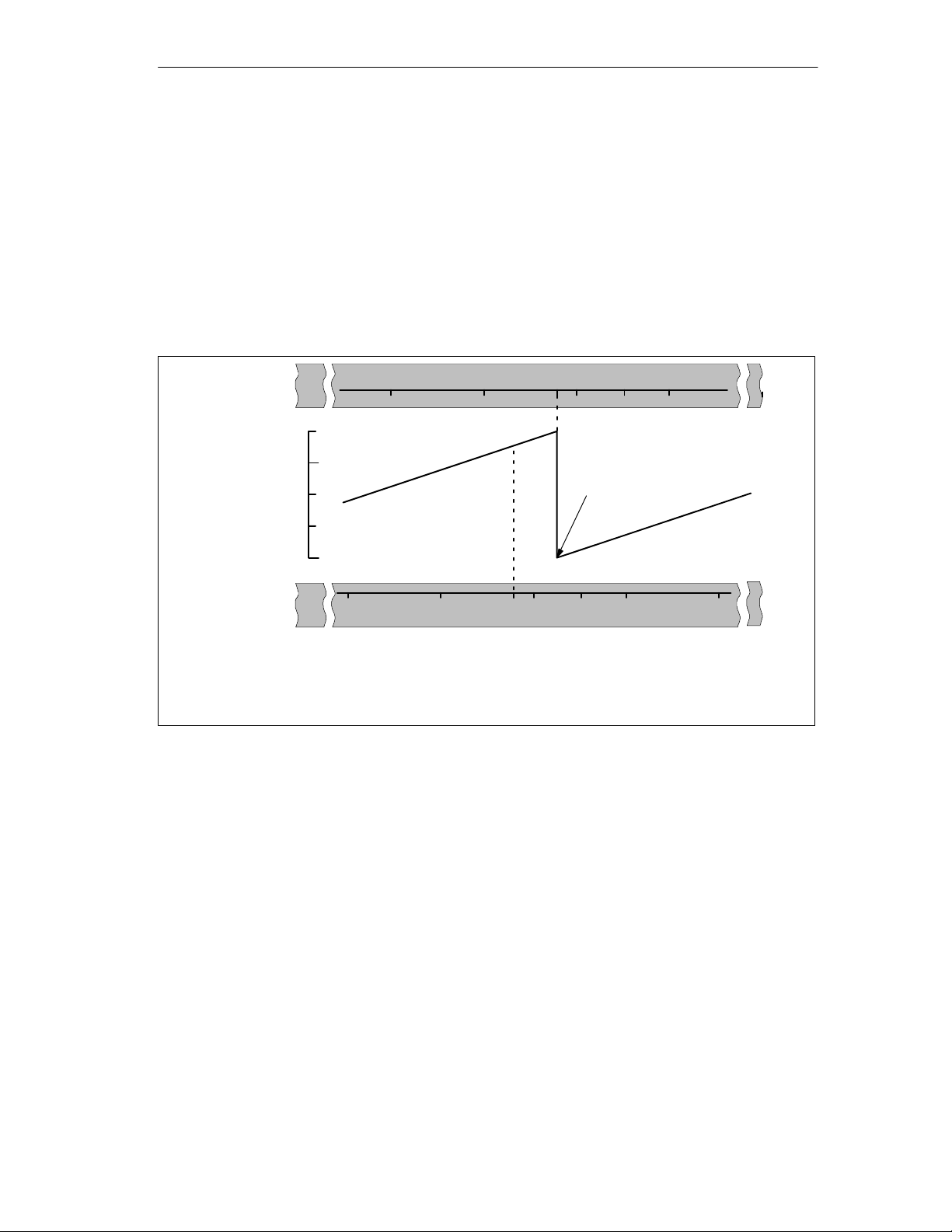
Example of Absolute Encoder Adjustment
In the example, the following is assumed:
• Reference-point coordinate = -125 mm
• Working range of SSW_STRT = -1000 mm to SSW_END = 1000 mm
• Absolute encoder adjustment = 0
• Encoder range = 2048 increments (= pulses) with a resolution of
1 mm/increment
• The absolute encoder used cannot be exactly adjusted mechanically and also
does not have the option of setting the actual value.
Machine Data and Cam Data
Instantaneous
Encoder
Axis
2047
Value of absolute encoder
0
–1000 0
Actual value
–125
1)
Encoder value 0
2)
Desired
1)
Correlation between the coordinate system and encoder values with the set absolute
Axis
–1000 10000–125
encoder adjustment. The encoder value 0 corresponds to the actual value -125.
2)
Required correlation of the coordinate system with the encoder. At this position the
coordinate should be -125.
FM 452 Electronic Cam Controller
C79000-G7076-C452-04
8-13
Page 82
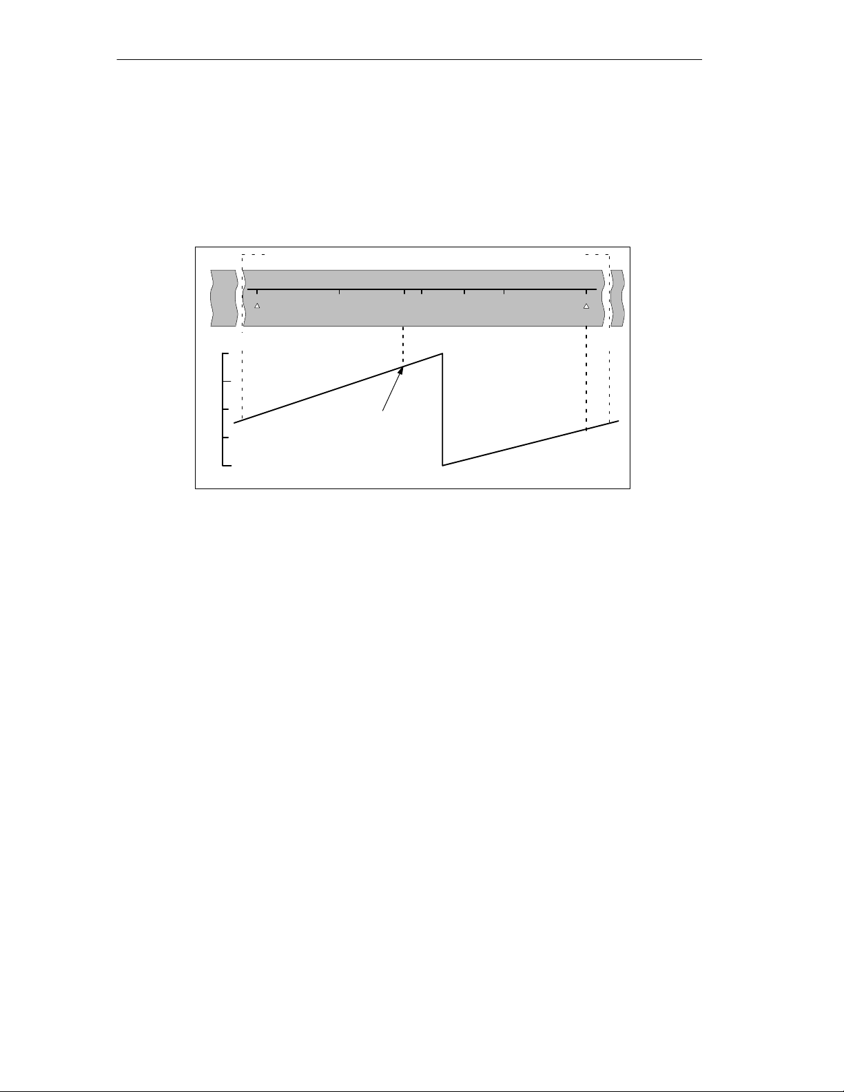
Machine Data and Cam Data
Result After Setting the Reference Point
After setting the reference point, the relationship between the encoder and
coordinate system is as follows:
The reference point coordinate on the axis (-125) is assigned to the encoder value
(1798) calculated from the absolute encoder adjustment.
Encoder range covered by this encoder
–1000 10000
–125
Axis
2047
Value of absolute encoder
0
Value from absolute
encoder adjustment
REF
1798
0
The encoder supplies 2048 defined values. The working range is defined by the
software limit switches. Due to the selected resolution of 1 mm per pulse, the
encoder can, however, cover a larger working area than intended with the software
limit switches.
With the set resolution the working range is already covered with 2001 values.
Therefore, in the example there are 47 pulses “left over” which lie symmetrically
about the working range.
Alternative: Mechanical Adjustment of an Encoder
SLESLS
1024–1023
875
8-14
You can obtain a correct relationship between the coordinate system and the
encoder as follows:
1. Move the axis to a reproducible position (for example the start software limit
switch).
2. Enter this coordinate value in the machine data as the reference point
coordinate.
3. Read the encoder value displayed at this position in the service dialog of the
user interface.
4. Enter this value as the absolute encoder adjustment in the machine data.
A correct actual value is then always displayed after parameter assignment.
Instead of steps 3. and 4., you can also set the encoder to zero with “Reset” (if this
exists) and enter the value “0” as the absolute encoder adjustment in the machine
data.
FM 452 Electronic Cam Controller
C79000-G7076-C452-04
Page 83

Machine Data and Cam Data
8.5 Machine Data of the Encoder
Definition
The encoder supplies position information to the module; the module evaluates this
information taking into account the resolution and calculates an actual value.
You can only be sure that the calculated actual value of the axis position matches
the actual axis position when the information in the machine data of the encoder is
correct.
Data in the Parameter DB
Address Name Type Initial V alue Comment
20.0 ENC_TYPE DINT L#1 Encoder type and frame length:
Range of values:
1 = 5 V incremetal
2 = 24 V incremental
3 = SSI 13-bit frame length
4 = SSI 25-bit frame length
5 = listen in
6 = 24 V initiator forwards
7 = 24 V initiator backwards
8 = SSI 13-bit (right-justified)
9 = SSI 25-bit (right-justified)
10 = listen in (right-justified)
With the “frame length”, you specify the clock frame output by the FM 452.
If you select “Listen”, you turn off the clock of the FM 452. The FM 452 can then listen in on other SSI
frames with a 13 or 25-bit frame length. The transmission rate depends on the cycle rate of the
master module.
FM 452 Electronic Cam Controller
C79000-G7076-C452-04
8-15
Page 84
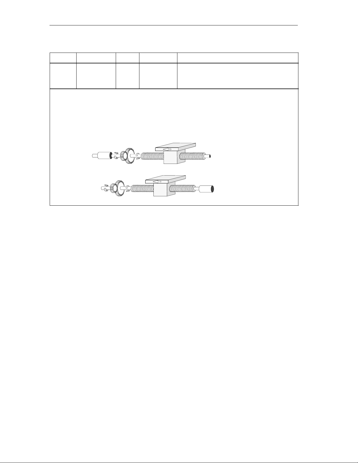
Machine Data and Cam Data
Address Name Type Initial Value Comment
24.0 DISP_REV DINT L#80000 Distance per encoder revolution :
Range of values:
1 m to 1 000 000 000 m
With the machine data “distance per encoder revolution” you inform the FM 452 of the distance
covered by the drive system per encoder revolution.
The value “distance per encoder revolution” depends on how the axis is set up and how the encoder is
installed. You must take into account all transmission components such as couplings or gearing.
Section 8.6 (Page 8-20) describes the relationship between the machine data “distance per Encoder
Revolution” and “increments per encoder revolution”.
Motor
Motor
Encoder
Gearing
Gearing
Encoder
8-16
FM 452 Electronic Cam Controller
C79000-G7076-C452-04
Page 85

Machine Data and Cam Data
Address Name Type Initial Value Comment
32.0 INC_REV DINT L#500 Increments per encoder revolution:
Range of values:
25
1 to 2
Note:
If you are using pulses as the unit, this entry has
no significance.
The “increments per encoder revolution” machine data specifies the number of increments output by an
encoder per revolution. Based on this value and the machine data “distance per encoder revolution”, the
FM 452 can calculate the resolution.
Incremental encoder
Any value from the range shown can be entered. One increment involves quadruple evaluation by the
module (see also Section 10.1, Page 10-2).
Initiator
Any value from the range shown can be entered.
Absolute encoder
The limits vary according to the type of encoder.
Encoder Type
Frame Length / Type Value Range
Can be used as
linear axis
Single-turn
Single-turn
Single-turn
Multi-turn
Multi-turn
Listen-in
Listen-in
13-bit half fir tree
13-bit right-justified
25-bit right-justified
25-bit fir tree
25-bit right-justified
Fir tree
right-justified
64 ... 8192 in powers of 2
64 ... 8192 all values
25
64 ... 2
all values
64 ... 8192 in powers of 2
24
64 ... 2
all values
64 ... 8192 in powers of 2
25
64 ... 2
all values
X
X
X
Special setting:
Multi-turn as
single-turn
25-bit half fir tree 64 ... 8192 in powers of 2
Note:
The number of pulses of an encoder is calculated from the machine data “increments per encoder
revolution” multiplied by “number of revolutions” (see page 8-20).
FM 452 Electronic Cam Controller
C79000-G7076-C452-04
8-17
Page 86

Machine Data and Cam Data
Address Name Type Initial Value Comment
36.0 NO_REV DINT L#1024 Number of encoder revolutions:
Range of values:
1 (single-turn encoder)
19
2 to 2
The machine data “number of encoder revolutions” is only necessary for absolute encoders. You use it
to define the number of revolutions possible with this encoder. For more information on absolute
encoders, read Section 10.3 in this manual.
Single-turn encoders
Only the value 1 is possible.
Multi-turn encoders
Multi-turn / Listen-in (fir tree): 2 ... 4096 in powers of 2.
19
Multi-turn / Listen-in (right-justified): 2 ... 2
Increment/encoder revolution number of encoder revolutions≤ 2
Linear measure
You can also connect a linear measure by entering the value 1.
Total number of steps of the encoder
The total number of steps is not part of the machine data.
Total no. of steps = increments per encoder revolution no. of revolutions
All values with the following restriction:
(multi-turn encoder)
25
.
Address Name Type Initial Value Comment
40.0 BAUDRATE DINT L#0 Baudrate:
Range of values: 0 = 125 kHz
1 = 250 kHz
2 = 500 kHz
3 = 1000 kHz
With the baudrate machine data, you define the speed of the data transfer from SSI encoders to the
FM 452.
This entry has no significance for incremental encoders.
The maximum cable length depends on the baudrate:
• 125 kHz 320 m
• 250 kHz 160 m
• 500 kHz 63 m
• 1000 kHz 20 m
8-18
FM 452 Electronic Cam Controller
C79000-G7076-C452-04
Page 87
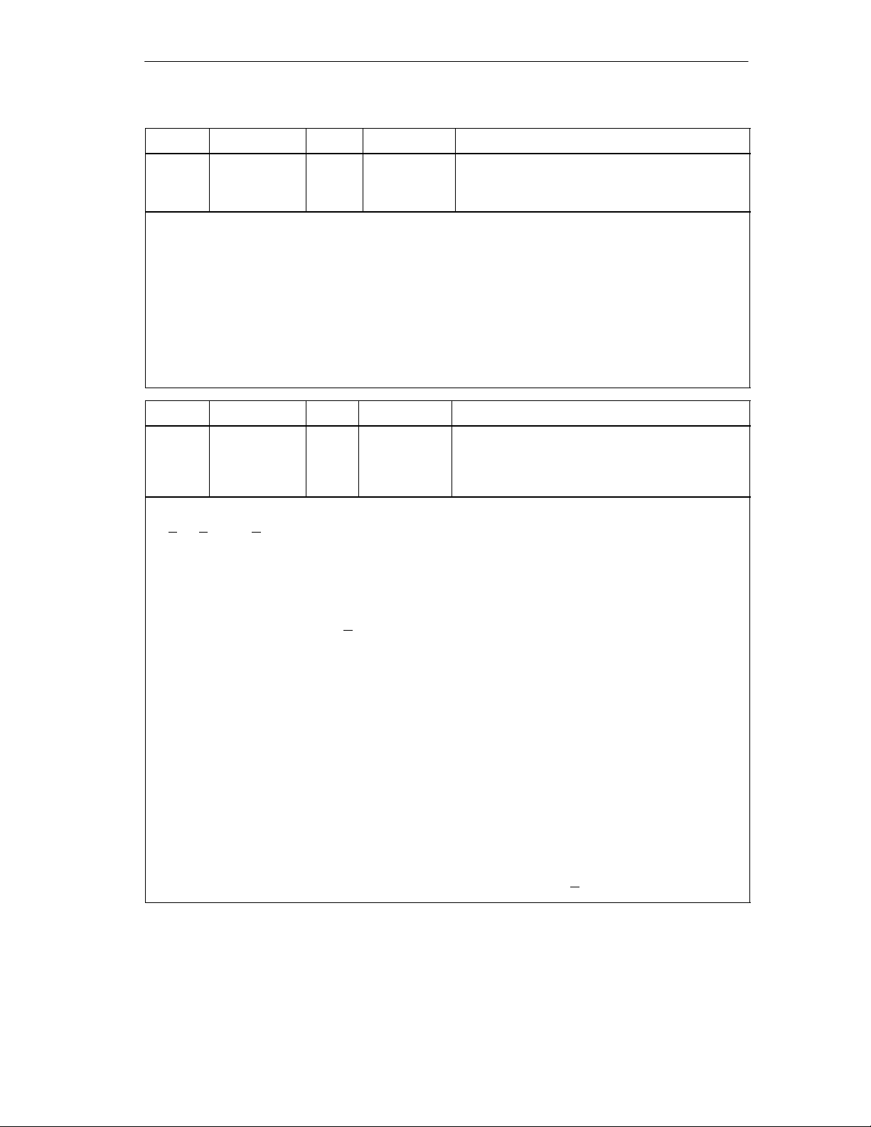
Machine Data and Cam Data
Address Name Type Initial Value Comment
59.0 CNT_DIR BOOL FALSE Count direction:
0 = normal
1 = inverted
With the machine data “count direction”, you match the direction of the position detection to the direction
of axis movement.
Y ou must also take into account all the directions of rotation of the transmission elements (for example
coupling and gearing).
• Normal = ascending count pulses (incremental encoder) or encoder values (absolute encoder)
correspond to ascending actual position values
• Inverted = ascending count pulses (incremental encoder) or encoder values (absolute encoder)
correspond to descending actual position values.
A lead time in conjunction with an absolute encoder (SSI) and inverted count direction is not
permitted.
Address Name Type Initial Value Comment
Monitoring:
63.0
63.1
63.2
Wire break
When monitoring is activated, the FM 452 monitors the signals
A, A, B, B, N and N of an incremental encoder. The monitoring detects:
MON_WIRE
MON_FRAME
MON_PULSE
BOOL
BOOL
BOOL
TRUE
TRUE
TRUE
1 = wire break
1 = frame error (must always be 1)
1 = missing pulses
• Wire break
• Short circuit on individual lines.
With incremental encoders without a zero marker, you must either
– deactivate the wire break monitoring or
– connect the signals N and N
externally (see Section 10.1)
• Edge-to-edge distance between the edges of the counted pulses.
• Failure of the encoder power supply.
Frame error
The frame error monitoring for absolute encoders (SSI) cannot be deactivated. It monitors the frame as
follows:
• Start and stop bit errors
• Monitoring of the monostable flip-flop period of the connected encoder
Missing pulses (incremental encoder)
An incremental encoder must always supply the same number of increments between two consecutive
zero markers.
The FM 452 checks whether the zero marker of an incremental encoder occurs at the correct encoder
status.
For encoders without zero markers, you must deactivate error pulse monitoring. You must also
deactivate wire break monitoring or connect the zero marker inputs N and N
externally.
FM 452 Electronic Cam Controller
C79000-G7076-C452-04
8-19
Page 88

Machine Data and Cam Data
RES
encoder rev
8.6 Resolution
Definition
The resolution is a measure of the accuracy of cam processing. It also determines
the maximum possible travel range.
The resolution (RES) is calculated as shown in the following table:
Input values • Travel per encoder revolution
Calculation
Incremental Encoders Absolute Encoders/Initiators
• Travel per encoder revolution
• Increments per encoder
revolution
• Pulse evaluation: quadruple
• Increments per encoder
revolution
• 1 increment = 1 pulse
• 1 increment = 4 pulses
distance
encoder rev
pulses
encoder rev
Note
In the pulses system of units, the resolution always has the value 1.
All position information is rounded up to the integral multiple of the resolution. This
allows you to distinguish between the entered and the used values.
8-20
FM 452 Electronic Cam Controller
C79000-G7076-C452-04
Page 89
Range of Values of the Resolution
The range for the resolution must be converted to the basic system of units. The
resolution must be kept within this range by selecting the values “distance per
encoder revolution” and “increments per encoder revolution”.
Based on the systems of units, the ranges for the resolution are as follows:
Machine Data and Cam Data
Example
System of
units
mm 10–3 mm 0.110–3 mm .... 100010–3 mm/pulse
inches 10–4 inches 0.110–4 inch .... 100010–4 inches/pulse
degrees 10–4 degrees
pulses 1 pulse 1
Specifications
in...
–3
degrees
10
10–2 degrees
Range for the Resolution
0.110–4 degrees .... 100010–4 degrees/pulse
–3
0.110
0.110–2 degrees .... 100010–2 degrees/pulse
degrees .... 100010–3 degrees/pulse
• An incremental encoder has the following data:
– Increments per encoder revolution: 5000
– Distance per encoder revolution: 1000 mm
– 1 increment = 4 pulses
This results in the following resolution (quadruple evaluation):
Resolution
1000 mm
=
5000 increments
0.0500
=
mm
pulse
=
0.2000
mm
increment 4 pulses
=
0.2000
mm
• An SSI encoder has the following data:
– Increments per encoder revolution: 4096
– Distance per encoder revolution: 1000 mm
– 1 increment = 1 pulse
This results in the following resolution:
Resolution
FM 452 Electronic Cam Controller
C79000-G7076-C452-04
1000 mm
=
4096 increments
=
0.2441
mm
increment
= 0.2441
mm
pulse
8-21
Page 90
Machine Data and Cam Data
Relationship Between Travel Range and Resolution
The travel range is limited by the numeric representation in the FM 452. The
number representation varies depending on the resolution. Therefore, make sure
that you are always within the permitted limits when specifying values.
The maximum travel range is represented in the table below:
Resolution (RES) is in the Range Maximum Travel Range
0.1
1
m
/
pulse
m
/
RES 1000
pulse
RES < 1
m
/
–108 m to 108 m (–100 m to + 100 m)
pulse
m
/
–109 m to 109 m (–1000 m to + 1000 m)
pulse
Relationship of the Feedrate and the Resolution
The feedrate displayed can be within the following limits depending on the
resolution (this information relates to units of millimeters):
• from 1
• from 1
The speed is calculated and filtered by the module every 4 ms.
m
m
/
to 90 m/
min
/
to 900 m/
min
at a resolution of 1
min
at a resolution of 1
min
m
/
pulse
m
/
pulse
It has at least an inaccuracy of one pulse/4 ms and is not suitable for closed-loop
control.
8-22
FM 452 Electronic Cam Controller
C79000-G7076-C452-04
Page 91

8.7 Number of Cams and Track Data
Number of Cams
The number of cams determines the cam cycle time and the maximum number of
cams that can be set.
Number of Cams Cam Cycle Time
16 cams 20.48 s
32 cams 40.96 s
64 cams 81.92 s
128 cams 163.84 s
Number of Cams in the Parameter DB:
Machine Data and Cam Data
Address Name Type Initial V alue Comment
76.0 C_QTY DINT UDT3: L#0
UDT4: L#1
UDT5: L#2
UDT6: L#3
Number of cams: 0 = max. 16 cams
1 = max. 32 cams
2 = max. 64 cams
3 = max. 128 cams
Track Data in the Parameter DB
Address Name Type Initial V alue Comment
90.0 TRACK_OUT WORD W#16#0 Activation of the track outputs:
Range:
0 = cam controller
1 = CPU
Bit number = track number
With the machine data “activation of the track outputs”, you specify how the track signals of tracks 0
to 15 are activated. Activation is possible via:
• Cam controller: The track signals are activated and deactivated by the cam processing of the
FM 452.
• CPU: The track signals represent the corresponding values of the track enables in the
channel DB.
This means that the track outputs can be activated specifically from within your program.
FM 452 Electronic Cam Controller
C79000-G7076-C452-04
8-23
Page 92

Machine Data and Cam Data
Address Name Type Initial Value Comment
Enable input:
95.0
..
..
95.7
A track signal Q3 to Q10 is activated in the following situation:
EN_IN_I3
..
..
EN_IN_I10
BOOL
..
..
BOOL
FALSE
..
..
FALSE
1 = track signal track 3 is ANDed with enable input
I3
..
1 = track signal track 10 is ANDed with enable
input I10
• the track is enabled with TRACK_EN and
• the appropriate external enable input I3 to I10 is set and
• the track result of the track is 1.
Address Name Type Initial Value Comment
Special tracks:
99.0
99.1
99.2
You can set tracks 0, 1 and 2 as special tracks.
SPEC_TRC0
SPEC_TRC1
SPEC_TRC2
BOOL
BOOL
BOOL
FALSE
FALSE
FALSE
1 = track 0 is counter cam track
1 = track 1 is counter cam track
1 = track 2 is brake cam track
Address Name Type Initial Value Comment
100.0
104.0
With this machine data, you specify the upper counter value for the set counter cam track.
CNT_LIM0
CNT_LIM1
DINT
DINT
L#2
L#2
Upper counter value counter cam track (track 0)
Upper counter value counter cam track(track 1)
Range:
2 ... 65535
8-24
FM 452 Electronic Cam Controller
C79000-G7076-C452-04
Page 93

8.8 Interrupt Enable
Definition
You can decide whether hardware interrupts are generated when certain events
occur (see Section 6.1, Page 6-2).
• Cam on/off
In the cam data, you can specify where the hardware interrupts are generated
when cams 0 to 7 are activated and/or deactivated (see Section 8.9,
Page 8-26).
• Measurement starts
With the “edge detection” setting, a rising edge at digital input I1 can trigger a
hardware interrupt.
• Measurement completed
Both with the “edge detection” setting and with the “length measurement”
setting, a falling edge at digital input I1 can trigger a hardware interrupt.
Machine Data and Cam Data
Machine Data for Interrupt Enable in the Parameter DB
Address
(absolute)
3.1 PI_MEND BOOL FALSE 1 = enable hardware interrupt: measurement end
3.2 PI_CAM BOOL FALSE 1 = enable hardware interrupt: cam on/off
3.5 PI_MSTRT BOOL FALSE 1 = enable hardware interrupt: measurement start
Name Type Initial Value Comment
Cam Data for Interrupt Enable in the Parameter DB
Address
(relative)
+0.4 PI_SW_ON BOOL FALSE 1 = hardware interrupt on activation
+0.5 PI_SW_OFF BOOL FALSE 1 = hardware interrupt on deactivation
Name Type Initial Value Comment
FM 452 Electronic Cam Controller
C79000-G7076-C452-04
8-25
Page 94
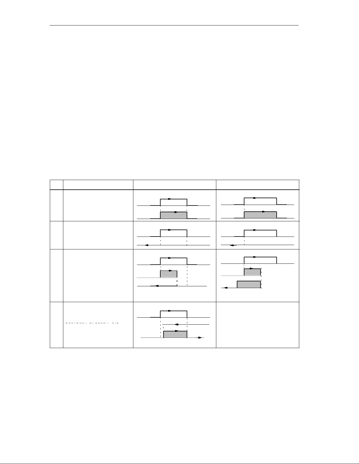
Machine Data and Cam Data
activation direction
direction o osite to the
t1
activation direction the
8.9 Cam Data
Definition
Cam data describe the characteristics of a cam, the assignment of each cam to a
track, and the switching behavior of the cam. The cam data listed below are set for
each individual cam.
• Only the cams you set as “true” will be interpreted and processed by the
module.
• Cams 0 to 7 have process interrupt capability.
• The number of cams that can be set depends the number available.
Switching Response of Cams Dependent on the Activation Direction
With the exception of example 5, the positive activation direction is assumed.
No. Description Distance cam Time cam
1
A cam is passed in the
activation direction
CS
CE
CS
On time
2
A cam is passed in the
pp
activation direction
3
A cam is approached in the
activation direction; while
the cam is active, the
direction of the axis is
changed.
4
A cam is approached in the
direction opposite to the
activation direction; the
direction of travel of the axis
changes to the activation
direction at the cam
CS
CS CE CS
CS CE Cam not switched
CE
CS
On time
On time
t1
t2
On time x = t1 + t2
x
8-26
FM 452 Electronic Cam Controller
C79000-G7076-C452-04
Page 95
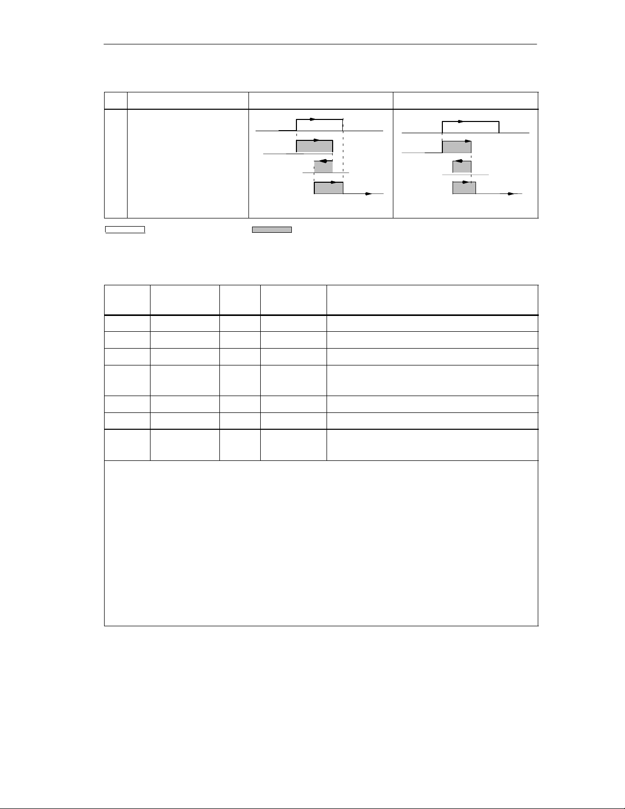
No. T ime camDistance camDescription
5
A cam is approached and
left in any direction; both
directions are set as the
activation direction.
Set cam Switched cam
Cam Data in the Parameter DB
CS
CE
Machine Data and Cam Data
On time
CS
On time x = t1 + t2 + t3
x
t1
t2
t3
Address
(relative)
+0.0 CAMV ALID BOOL FALSE 1 = cam valid
+0.1 EFFDIR_P BOOL TRUE 1 = activation direction positive (plus)
+0.2 EFFDIR_M BOOL TRUE 1 = activation direction negative (minus)
+0.3 CAM_TYPE BOOL FALSE 0 = distance cam
+0.4 PI_SW_ON BOOL FALSE 1 = hardware interrupt on activation
+0.5 PI_SW_OFF BOOL FALSE 1 = hardware interrupt on deactivation
+1.0 TRACK_NO BYTE B#16#0 Track number
Activation direction
Two activation directions are possible:
positive: The cam is activated at the cam start when the axis is moving in the direction of ascending
actual values.
negative: The cam is activated at the cam end when the axis is moving in the direction of
descending actual values.
You can also set both activation directions at the same time.
Track number
With the track number, you define the track with which each cam is effective.
Name Type Initial Value Comment
1 = time cam
Range: 0 to 31
Note:
Unused cams should always be set to “invalid” (CAMVALID = FALSE).
FM 452 Electronic Cam Controller
C79000-G7076-C452-04
8-27
Page 96
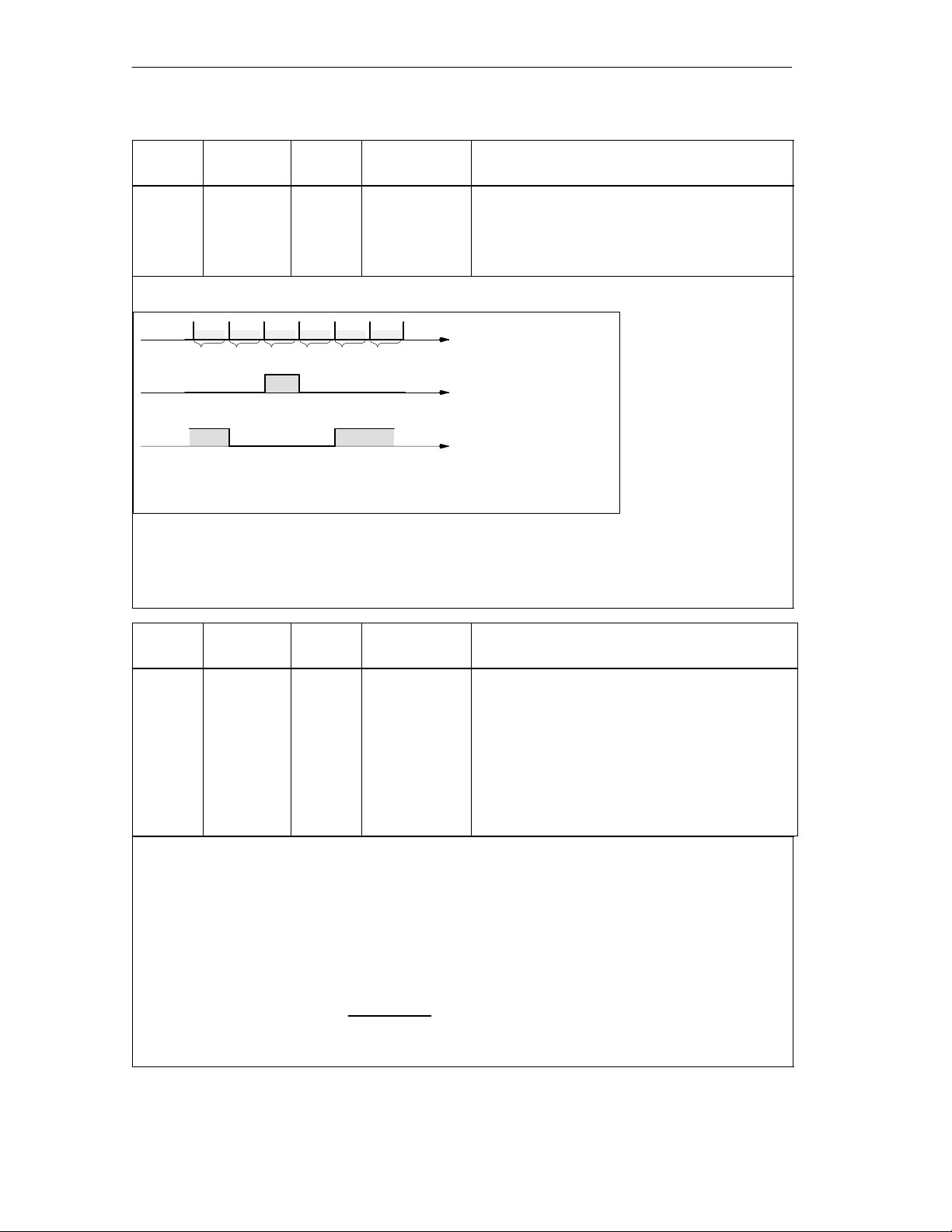
Machine Data and Cam Data
Address
(relative)
+2.0
+6.0
Minimum Length of a Distance Cam
CS = cam start; CE = cam end
Figure 8-3 Shortest Cam with the Axis Moving in the Positive Direction
The inactive part of a cam must always have a minimum clearance of four pulses between the cam end
(CE) and cam start (CS).
If CE = CS, the cam is activated for one pulse.
Name Type Initial Value Comment
For distance cams
CBEGIN
CEND
101 102 103 104 105
CE
DINT
DINT
CS = CE
106
CS
L#–100000000
L#100000000
s
s
Cam start (CS)
Cam end (CE)
Range:
– 1 000 000 000 m to 1 000 000 000 m
Pulses; calculated from
the encoder signals
Shortest cam
CS = 103 and CE = 103
Shortest non–active
cam, when CS is
greater than CE:
CS = 105 and CE = 101
Address
(relative)
+2.0
+6.0
With a time cam, you specify a cam start and an “on time” instead of a cam end. You can specify the on
time in increments of 100 s. The time starts to run when the cam is activated.
The following conditions apply for specifying the times
Name Type Initial Value Comment
For time cams
CBEGIN
CEND
DINT
DINT
L#–100000000
L#100000000
Cam start (CS)
Cam end (CE)
On Time
Range:
(0 to 13421) 100 s with a maximum of 16 cams
(0 to 26843) 100 s with a maximum of 32 cams
(0 to 53686) 100 s with a maximum of 64 cams
(0 to 65535) 100 s with a maximum of 128 cams
• 0 s: A cam with the on time 0 s is never activated.
• 0 s < t 400 s: The FM 452 sets a minimum cam time of approximately 330 s.
• t > 400 s: The FM 452 calculates the actual on time t
the following formula:
t
t
=
integer
act
The maximum error is always less than one cam cycle period.
(
cam cycle
spec
Cam cycle time
)
from the specified on time t
act
according to
spec
8-28
FM 452 Electronic Cam Controller
C79000-G7076-C452-04
Page 97

Machine Data and Cam Data
Address
(relative)
+ 10.0 LTIME INT 0 Lead Time
Delays in the connected switching elements can be compensated by specifying a lead time. You enter
the lead time in steps of 100 s. You can assign a lead time for each cam. The lead time applies to the
cam start and cam end.
Lead Distance
The lead distance of a cam is recalculated depending on the current feedrate and the lead time. The
entire cam is shifted in the direction of the actual value by this distance. The range set is known as the
“static range” and the range calculated based on the lead time is known as the “dynamic range”.
Lead distance = lead time current feedrate.
Calculation of the lead distance of all cams is made within 1/4 of the longest set lead time on the
FM 452. If you set a very high lead time for a cam, the dynamic adjustment is calculated less often.
Actual Lead Time
You can calculate the actual lead time as follows:
Calculate the cam cycle time: This is the time in which the FM 452 has completely processed all
cams and depends on the number of cams in use (see table Page 8-23).
Calculate the actual lead time with the following formula:
Where:
Lead time
Lead time I is the lead time you specified.
Integer () means that in the calculation inside the brackets, only the value before the decimal point is
taken into account.
The maximum error of the lead time
Example:
The following values are specified:
Number of cams: maximum of 32 cams
cam cycle time: 40.96 µs
lead time
Result: You obtain an actual lead time of 983 µs.
A lead time in conjunction with an absolute encoder (SSI) and inverted count direction is not
permitted.
Name Type Initial Value Comment
Range:
(0 to 53686) 100 s with a maximum of 16 cams
(0 to 65535) 100 s with a maximum of 32, 64 or 128 cams
Lead time
is the lead time set by the FM 452
act
= 1000 µs
L
= integer
act
(
Cam cycle time 4
is always less than the cam cycle time 4.
act
Lead time
I
Cam cycle time 4
)
Note
The actual lead time is always less than the set lead time. It can be 0 even though
the set lead time is 100 s.
The lead distance on a rotary axis must be less than the rotary axis range and the
non-active part of the cam. This must be guaranteed for all speeds.
FM 452 Electronic Cam Controller
C79000-G7076-C452-04
8-29
Page 98
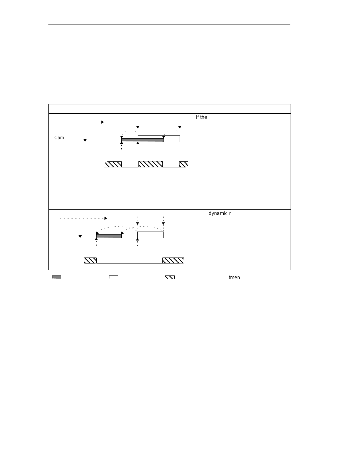
Machine Data and Cam Data
Dynamic Adjustment on a Cam
There are two distinct situations relating to the range of the cam:
1. The static and dynamic range of the cam overlap.
2. The static and dynamic range of the cam do not overlap.
Table 8-1 Dynamic Adjustment on a Cam (Different Cases)
Direction of travel
Actual value
Cam
Dynamic adjustment
Direction of travel
Actual value
Cam
Dynamic
adjustment
Dynamic Adjustment
Lead distance
Lead distance
Description
CECS
If the dynamic range of the cam overlaps
the static range of the cam, the following
applies:
• If the dynamic range of the cam has
been reached, the cam is activated.
At the same time, calculation of a
new dynamic adjustment is disabled.
• If the actual value reaches the static
range of the cam, the calculation of a
new dynamic adjustment is enabled
again, a change in feedrate affects
the cam end.
• If the cam is deactivated at the end
of the dynamic range, dynamic
adjustment is disabled again until the
end of the static range of the cam.
CECS
If the dynamic range of the cam does
not overlap the static range of the cam,
the following applies:
• If the dynamic range of the cam has
been reached, the cam is activated.
At the same time, calculation of a
new dynamic adjustment is disabled.
• At the end of the static range of the
cam, dynamic adjustment is enabled
again.
8-30
Dynamic range
Static range
A new dynamic adjustment is possible
FM 452 Electronic Cam Controller
C79000-G7076-C452-04
Page 99

Settings
Chapter Overview
Section Contents Page
9.1 Influence of the Settings on the Switching Response of Time
9.2 Set Actual Value / Set Actual Value on-the-fly / Reset Actual
9.3 Zero Offset 9-6
9.4 Set Reference Point 9-9
9.5 Changing the Cam Edges 9-11
9.6 Fast Cam Parameter Change 9-13
9.7 Length Measurement / Edge Acqusition 9-15
9.8 Retrigger Reference Point 9-19
9.9 Deactivating Software Limit Switches 9-22
9.10 Simulation 9-23
9.11 Counted Values of the Counter Cam Tracks 9-25
9.12 Position and Track Data 9-26
9.13 Encoder Data 9-27
9.14 Cam and Track Data 9-28
9.15 Control Signals for the Cam Controller 9-29
9.16 Return Signals for the Cam Controller 9-30
9.17 Return Signals for Diagnostics 9-31
9
9-2
Cams
9-3
Value
This chapter explains how to use the settings along with a parameter DB.
FM 452 Electronic Cam Controller
C79000-G7076-C452-04
9-1
Page 100

Settings
9.1 Influence of Settings on the Switching Response of Time Cams
Actual Value Changes
A time cam can be skipped by the following settings that change the actual value:
• Set actual value
• Set actual value on-the-fly
• Zero offset
• Retrigger reference point
Switching a Time Cam
If you skip the start of a time cam due to one of the settings listed above, this cam
is activated as long as the actual direction in which the axis is moving matches the
activation direction set for the cam. The set on time runs until it expires.
Note
If the axis is stationary, the direction of movement depends on fluctuations in the
actual value.
If you want the direction of movement to be taken into account when the axis is
stationary, you must set a hysteresis that is greater than the fluctuations in the
actual value when the axis is stationary.
If the axis is not moving, the last detected direction of movement is retained.
Warning
!
Injury to persons or damage to equipment can occur.
With a rotary axis, settings that modify the actual value can led to accidental
activation of time cams.
You should always set the time cams of a rotary axis to “invalid” if you want to
modify the actual value using the settings listed above.
9-2
FM 452 Electronic Cam Controller
C79000-G7076-C452-04
 Loading...