

Page 1

Preface, Contents
SIMATIC
Field PG
Manual
Important Notes
Getting Familiarized with the
SIMATIC Field PG
Configuring And Operating The
SIMATIC Field PG
SIMATIC Field PG Expansions
Configuring the SIMATIC Field
PG
Error Diagnostics
Hardware Information
Reinstallation of the Software
Appendices
1
2
3
4
5
6
7
8
Edition 01/2002
A5E00075760-04
ESD Guidelines
Technical Specifications
Glossary, Index
A
B
Page 2
AChapterChapterOChapter
Safety Guidelines
This manual contains notices intended to ensure personal safety, as well as to protect the products and
connected equipment against damage. These notices are highlighted by the symbols shown below and
graded according to severity by the following texts:
Danger
!
indicates that death, severe personal injury or substantial property damage will result if proper precautions
are not taken.
Warning
!
indicates that death, severe personal injury or substantial property damage can result if proper
precautions are not taken.
Caution
!
indicates that minor personal injury can result if proper precautions are not taken.
Caution
indicates that property damage can result if proper precautions are not taken.
Notice
draws your attention to particularly important information on the product, handling the product, or to a
particular part of the documentation.
Qualified Personnel
Repair, maintenance and servicing of device only to be carried out by qualified personnel. Qualified
persons are defined as persons who are authorized to commission, to ground and to tag circuits,
equipment, and systems in accordance with established safety practices and standards.
Correct Usage
Note the following:
Warning
!
Trademarks
The reproduction, transmission or use of this document or its
contents is not permitted without express written authority.
Offenders will be liable for damages. All rights, including rights
created by patent grant or registration of a utility model or
design, are reserved.
Siemens AG
Bereich Automation and Drives
Geschaeftsgebiet Industrial Automation Systems
Postfach 4848, D- 90327 Nuernberg
Index-2
Siemens Aktiengesellschaft A5E00075760
This device and its components may only be used for the applications described in the catalog or the
technical description, and only in connection with devices or components from other manufacturers which
have been approved or recommended by Siemens.
This product can only function correctly and safely if it is transported, stored, set up, and installed
correctly, and operated and maintained as recommended.
SIMATIC, SIMATIC HMI and SIMATIC NET are registered trademarks of SIEMENS AG.
Third parties using for their own purposes any other names in this document which refer to trademarks
might infringe upon the rights of the trademark owners.
Disclaim of LiabilityCopyright Siemens AG 2002 All rights reserved
We have checked the contents of this manual for agreement
with the hardware and software described. Since deviations
cannot be precluded entirely, we cannot guarantee full
agreement. However, the data in this manual are reviewed
regularly and any necessary corrections included in
subsequent editions. Suggestions for improvement are
welcomed.
Siemens AG 2002
Technical data subject to change.
EWA 4NEB 780 6023-01
Field PG
Page 3

Preface
Purpose of the Manual
This manual contains all the information you need for commissioning and using the
SIMATIC Field PG programming device.
It is intended both for programming and testing/debugging personnel who
commission the device itself and connect it with other units (automation systems,
further programming devices) as well as for service and maintenance personnel
who install expansions or carry out fault/error analyses.
Where is this Manual Valid?
This manual is valid for all supplied variations of the SIMATIC Field PG and
describes the state of delivery in January 2002.
Certifications, Standards and Approvals
Certifications
The device fulfils the following guidelines and certifications:
• EU guideline 73/23/EEC on low voltages
• EU guideline 89/336/EEC on electromagnetic compatibility
• Underwriters Laboratories (UL) to Standard UL 1950
• Canadian Standard Association (CSA) to Standard C22.2 No. 950
Standards and Approvals
The device fulfils the requirements for the CE approval. Approvals for UL and CSA
are available.
Further information on the approvals, certificates, and licenses for your device is
provided in Chapter 1.
Incorporation into the Communications Environment
This manual forms part of the supplied CD “Backup PG”.
For supplementary instructions on how to handle the software please refer to the
corresponding manuals (for example, the STEP 7 Manual).
SIMATIC Field PG Manual
A5E00075760-04
iii
Page 4

Preface
Structure of the Manual
Chapters 1 to 5 of the manual contain the most important instructions for
commissioning and using the Field PG. Chapters 6 to 8 are reference sections
required in special situations.
Important Notes
This chapter contains information on security, certificates, guidelines and
approbations.
Familiarizing Yourself
Before you initially start using the Field PG, you should inform yourself about its
components and their functions in Chapter 2.
Configuration and Operation
Before you start to use your programming device, you should read about the
components and functions of the SIMATIC Field PG in Chapter
LEERER MERKER.
Installation
Chapter LEERER MERKER describes the basic steps necessary for
commissioning the Field PG. This chapter also contains instructions for working
with submodules and memory cards for programmable logic controllers and
additional interfaces.
Expansion
Chapter 4 describes how to expand your SIMATIC Field PG (for example,
installation of memory expansions). Please observe the safety instructions in this
section.
Configuration
Modifications made to the system hardware may make it necessary for you to
adapt the original hardware configuration. This is described in Chapter 5.
Error/fault diagnostics
Chapter 6 explains how to deal with simple faults and problems that you can
diagnose and, in some cases, eliminate yourself.
Reference data
Chapter 7 contains information about hardware addresses, interrupt assignments,
and connecting cables.
Reinstalling the Software
If it does happen that you need to reinstall the software you can find the
procedures in Chapter 8.
ESD guidelines
The guidelines on the handling of electrostatic-sensitive devices are particularly
important for service and maintenance technicians who are installing expansion
units or carrying out error analysis with the SIMATIC Field PG.
iv
SIMATIC Field PG Manual
A5E00075760-04
Page 5

Glossary
The glossary defines and explains important terms.
Alphabetical index
The alphabetical index will help you to find passages in the text relating to
important terms and keywords quickly and reliably.
Conventions
The abbreviation PG oder device is also used within this manual for the product
designation SIMATIC Field PG.
Further Support
If you have questions related to the use of the products which are not answered in
this manual, please consult your Siemens representative in your local agency. You
will also find your representatives for repairs and spare parts at
Preface
http://www.ad.siemens.de/partner
Trainingscenter
Siemens offers a number of training courses to familiarize you with the SIMATIC
S7 automation system. Please contact your regional training center or our central
training center in D 90327 Nuremberg, Germany for details.
Telephone: +49 (911) 895-3200
http://www.sitrain.com/
SIMATIC Documentation on the Internet
You will find the documentation on the internet at:
http://www.ad.siemens.de/support
Use the Knowledge Manager to find the documentation you need quickly. If you
have any questions or suggestions concerning the documentation you can use the
”Documentation” conference in the internet forum.
SIMATIC Field PG Manual
A5E00075760-04
v
Page 6

Preface
Automation an Drives, Service & Support
Available worldwide, around the clock:
Nuremberg
Johnson City
SIMATIC Basic Hotline
Singapore
Worldwide (Nuremberg)
T echnical Support
(Free Contact)
Local time: Mo.–Fr. 7:00 to 17:00
Phone: +49 (180) 5050 222
Fax: +49 (180) 5050 223
E-mail: techsupport@
ad.siemens.de
GMT: +1:00
Europe / Africa (Nuremberg)
Authorization
Local time: Mo.–Fr. 7:00 to 17:00
Phone: +49 (911) 895-7200
Fax: +49 (911) 895-7201
E-mail: authorization@
nbgm.siemens.de
GMT: +1:00
German and English are spoken on all the SIMATIC hotlines, French, Italian and Spanish are also spoken on the
authorization hotline.
Worldwide (Nuremberg)
T echnical Support
(charged, only with
SIMATIC Card)
Local time: Mo.–Fr. 0:00 to 24:00
Phone: +49 (911) 895-7777
Fax: +49 (911) 895-7001
GMT: +01:00
America (Johnson City)
T echnical Support and
Authorization
Local time: Mo.–Fr. 8:00 to 19:00
Phone: +1 423 461-2522
Fax: +1 423 461-2289
E-mail: simatic.hotline@
sea.siemens.com
GMT: –5:00
Asia / Australia (Singapore)
T echnical Support and
Authorization
Local time: Mo.–Fr. 8:30 to 17:30
Phone: +65 740-7000
Fax: +65 740-7001
E-mail: simatic.hotline@
sae.siemens.com.sg
GMT: +8:00
vi
SIMATIC Field PG Manual
A5E00075760-04
Page 7

Service & Support on the Internet
In addition to our documentation, we offer our Know-how online on the internet at:
http://www.ad.siemens.de/support
where you will find the following:
• Current Product Information leaflets, FAQs (Frequently Asked Questions),
Downloads, Tips and Tricks.
• A newsletter giving you the most up-to-date information on our products.
• The Knowledge Manager helps you find the documents you need.
• Users and specialists from all over the world share information in the forum.
• Your local customer service representative for Automation & Drives in our
customer service representative data bank.
• Information on field service, repairs, spare parts and more under ”Services”.
Preface
SIMATIC Field PG Manual
A5E00075760-04
vii
Page 8

Preface
viii
SIMATIC Field PG Manual
A5E00075760-04
Page 9

Contents
Preface iii. . . . . . . . . . . . . . . . . . . . . . . . . . . . . . . . . . . . . . . . . . . . . . . . . . . . . . . . . . . . . . . .
1 Important Notes 1-1. . . . . . . . . . . . . . . . . . . . . . . . . . . . . . . . . . . . . . . . . . . . . . . . . . . . . . . .
1.1 Safety Instructions 1-1. . . . . . . . . . . . . . . . . . . . . . . . . . . . . . . . . . . . . . . . . . . . . . .
1.2 Certificates, Directives and Declarations 1-2. . . . . . . . . . . . . . . . . . . . . . . . . . . .
1.3 Certification for the USA, Canada and Australia 1-3. . . . . . . . . . . . . . . . . . . . .
1.4 Cleaning and Transporting the Field PG 1-5. . . . . . . . . . . . . . . . . . . . . . . . . . . .
2 Getting Familiarized with the SIMATIC Field PG 2-1. . . . . . . . . . . . . . . . . . . . . . . . . . .
2.1 Components of the SIMATIC Field PG 2-2. . . . . . . . . . . . . . . . . . . . . . . . . . . . .
2.2 Keyboard 2-9. . . . . . . . . . . . . . . . . . . . . . . . . . . . . . . . . . . . . . . . . . . . . . . . . . . . . .
2.3 Touchpad 2-13. . . . . . . . . . . . . . . . . . . . . . . . . . . . . . . . . . . . . . . . . . . . . . . . . . . . . .
2.4 LED displays 2-14. . . . . . . . . . . . . . . . . . . . . . . . . . . . . . . . . . . . . . . . . . . . . . . . . . .
2.5 On/Off Pushbutton (Power Button) 2-15. . . . . . . . . . . . . . . . . . . . . . . . . . . . . . . . .
2.6 Drives 2-17. . . . . . . . . . . . . . . . . . . . . . . . . . . . . . . . . . . . . . . . . . . . . . . . . . . . . . . . .
2.6.1 Floppy Disk Drive 2-17. . . . . . . . . . . . . . . . . . . . . . . . . . . . . . . . . . . . . . . . . . . . . . .
2.6.2 Hard Disk Drive 2-19. . . . . . . . . . . . . . . . . . . . . . . . . . . . . . . . . . . . . . . . . . . . . . . . .
2.6.3 Optical Drive 2-19. . . . . . . . . . . . . . . . . . . . . . . . . . . . . . . . . . . . . . . . . . . . . . . . . . . .
2.7 External Power Unit and Battery 2-21. . . . . . . . . . . . . . . . . . . . . . . . . . . . . . . . . . .
3 Configuring And Operating The SIMATIC Field PG 3-1. . . . . . . . . . . . . . . . . . . . . . . .
3.1 Unpacking and Setting Up the SIMATIC Field PG 3-2. . . . . . . . . . . . . . . . . . . .
3.2 Connecting to the Power Supply 3-4. . . . . . . . . . . . . . . . . . . . . . . . . . . . . . . . . . .
3.3 Battery Operation 3-5. . . . . . . . . . . . . . . . . . . . . . . . . . . . . . . . . . . . . . . . . . . . . . .
3.4 Commissioning 3-8. . . . . . . . . . . . . . . . . . . . . . . . . . . . . . . . . . . . . . . . . . . . . . . . .
3.4.1 Cold Start of the SIMATIC Field PG 3-8. . . . . . . . . . . . . . . . . . . . . . . . . . . . . . . .
3.4.2 Restart of the SIMATIC Field PG 3-10. . . . . . . . . . . . . . . . . . . . . . . . . . . . . . . . . .
3.5 Panel “Field PG” 3-11. . . . . . . . . . . . . . . . . . . . . . . . . . . . . . . . . . . . . . . . . . . . . . . .
3.6 Connecting Peripheral Devices 3-12. . . . . . . . . . . . . . . . . . . . . . . . . . . . . . . . . . . .
3.7 Working with SIMATIC S5 Memory Submodules 3-15. . . . . . . . . . . . . . . . . . . . .
3.8 Working with SIMATIC Memory Cards 3-16. . . . . . . . . . . . . . . . . . . . . . . . . . . . .
3.9 Working with Micro Memory Cards 3-17. . . . . . . . . . . . . . . . . . . . . . . . . . . . . . . . .
3.10 Working with PC Cards 3-18. . . . . . . . . . . . . . . . . . . . . . . . . . . . . . . . . . . . . . . . . .
3.11 Connecting the Field PG to a SIMATIC S5 Network 3-19. . . . . . . . . . . . . . . . . .
SIMATIC Field PG Manual
A5E00075760-04
ix
Page 10

Contents
3.12 Connecting the Field PG to a SIMATIC S7 Network (MPI/DP) 3-20. . . . . . . . .
3.13 Networking the Field PG with Other Stations on PROFIBUS 3-22. . . . . . . . . .
3.14 Ethernet (RJ45 Ethernet Interface) 3-22. . . . . . . . . . . . . . . . . . . . . . . . . . . . . . . .
4 SIMATIC Field PG Expansions 4-1. . . . . . . . . . . . . . . . . . . . . . . . . . . . . . . . . . . . . . . . . . .
4.1 Installing Memory Expansion Submodules 4-2. . . . . . . . . . . . . . . . . . . . . . . . . .
4.2 Processor Upgrade 4-4. . . . . . . . . . . . . . . . . . . . . . . . . . . . . . . . . . . . . . . . . . . . . .
4.3 Replacing Backup Battery 4-4. . . . . . . . . . . . . . . . . . . . . . . . . . . . . . . . . . . . . . . .
5 Configuring the SIMATIC Field PG 5-1. . . . . . . . . . . . . . . . . . . . . . . . . . . . . . . . . . . . . . .
5.1 Changing the Device Configuration with SETUP 5-2. . . . . . . . . . . . . . . . . . . . .
5.2 The Main Menu 5-5. . . . . . . . . . . . . . . . . . . . . . . . . . . . . . . . . . . . . . . . . . . . . . . . .
5.3 The Advanced Menu 5-14. . . . . . . . . . . . . . . . . . . . . . . . . . . . . . . . . . . . . . . . . . . . .
5.4 The Security Menu 5-16. . . . . . . . . . . . . . . . . . . . . . . . . . . . . . . . . . . . . . . . . . . . . .
5.5 The Power Menu 5-17. . . . . . . . . . . . . . . . . . . . . . . . . . . . . . . . . . . . . . . . . . . . . . . .
5.6 The Boot Menu 5-19. . . . . . . . . . . . . . . . . . . . . . . . . . . . . . . . . . . . . . . . . . . . . . . . .
5.7 The Version Menu 5-21. . . . . . . . . . . . . . . . . . . . . . . . . . . . . . . . . . . . . . . . . . . . . . .
5.8 The Exit Menu 5-22. . . . . . . . . . . . . . . . . . . . . . . . . . . . . . . . . . . . . . . . . . . . . . . . . .
6 Error Diagnostics 6-1. . . . . . . . . . . . . . . . . . . . . . . . . . . . . . . . . . . . . . . . . . . . . . . . . . . . . . .
7 Hardware Information 7-1. . . . . . . . . . . . . . . . . . . . . . . . . . . . . . . . . . . . . . . . . . . . . . . . . . .
7.1 System Resources 7-2. . . . . . . . . . . . . . . . . . . . . . . . . . . . . . . . . . . . . . . . . . . . . .
7.2 Interface Pinout 7-3. . . . . . . . . . . . . . . . . . . . . . . . . . . . . . . . . . . . . . . . . . . . . . . . .
7.3 Patch Cords 7-10. . . . . . . . . . . . . . . . . . . . . . . . . . . . . . . . . . . . . . . . . . . . . . . . . . . .
8 Reinstallation of the Software 8-1. . . . . . . . . . . . . . . . . . . . . . . . . . . . . . . . . . . . . . . . . . .
8.1 Cause / Remedy 8-2. . . . . . . . . . . . . . . . . . . . . . . . . . . . . . . . . . . . . . . . . . . . . . . .
8.2 Restoring the Hard Disk (Data Deleted) 8-3. . . . . . . . . . . . . . . . . . . . . . . . . . . .
8.2.1 Creating Partitions under Windows Me 8-3. . . . . . . . . . . . . . . . . . . . . . . . . . . . .
8.2.2 Creating Partitions under Windows 2000 8-4. . . . . . . . . . . . . . . . . . . . . . . . . . .
8.2.3 Creating Partitions under Windows NT 8-5. . . . . . . . . . . . . . . . . . . . . . . . . . . . .
8.3 Installing the Operating System Windows Me 8-7. . . . . . . . . . . . . . . . . . . . . . .
8.3.1 Installing Drivers under Windows Me 8-8. . . . . . . . . . . . . . . . . . . . . . . . . . . . . . .
8.4 Installing Drivers and Software 8-8. . . . . . . . . . . . . . . . . . . . . . . . . . . . . . . . . . . .
8.5 Installing the Operating System Windows 2000 8-9. . . . . . . . . . . . . . . . . . . . . .
8.5.1 Installing Drivers under Windows 2000 8-11. . . . . . . . . . . . . . . . . . . . . . . . . . . . .
8.6 Installing the Operating System Windows NT 8-12. . . . . . . . . . . . . . . . . . . . . . .
8.7 Installing the SIMATIC Software 8-14. . . . . . . . . . . . . . . . . . . . . . . . . . . . . . . . . . .
x
SIMATIC Field PG Manual
A5E00075760-04
Page 11

Contents
A Guidelines for Handling Electrostatically-Sensitive Devices (ESD) A-1. . . . . . . . .
A.1 What is ESD? A-2. . . . . . . . . . . . . . . . . . . . . . . . . . . . . . . . . . . . . . . . . . . . . . . . . . .
A.2 Electrostatic Charging of Persons A-3. . . . . . . . . . . . . . . . . . . . . . . . . . . . . . . . .
A.3 General Protective Measures Against Electrostatic
Discharge Damage A-4. . . . . . . . . . . . . . . . . . . . . . . . . . . . . . . . . . . . . . . . . . . . . .
B Technical Specifications B-1. . . . . . . . . . . . . . . . . . . . . . . . . . . . . . . . . . . . . . . . . . . . . . . .
Glossary Glossary-1. . . . . . . . . . . . . . . . . . . . . . . . . . . . . . . . . . . . . . . . . . . . . . . . . . . . . . . . . .
Index Index-1. . . . . . . . . . . . . . . . . . . . . . . . . . . . . . . . . . . . . . . . . . . . . . . . . . . . . . . . . . . . . . . .
SIMATIC Field PG Manual
A5E00075760-04
xi
Page 12

Contents
xii
SIMATIC Field PG Manual
A5E00075760-04
Page 13

Important Notes
1.1 Safety Instructions
Caution
!
Notes on Inserting and Removing Modules
The safety instructions given on the backside of the title page of this manual must
be observed. Before adding to the Field PG’s functionality by expanding the
hardware configuration (see Chapter 4) observe the relevant safety instructions.
Modules containing electrostatically sensitive devices (ESDs) can be identified by
the following label:
1
Please observe and carefully follow the guidelines mentioned below when handling
modules equipped with electrostatically sensitive devices:
• Always discharge your body’s static electricity before handling modules
equipped with ESDs (for example by touching a grounded object).
• Devices and tools must be free of static electricity.
• Always pull the power plug and disconnect the battery before connecting or
disconnecting modules (containing ESDs).
• Touch modules fitted with ESDs by their edges only.
• Never touch wiring posts or printed conductors on modules (containg ESDs).
SIMATIC Field PG Manual
A5E00075760-04
1-1
Page 14

Important Notes
1.2 Certificates, Directives and Declarations
Notes on the CE Symbol
The following applies to the SIMATIC product described in this operating
instruction:
EMC Directive
This product fulfils the requirements for the EC directive 89/336/EEC on
“electromagnetic compatibility” and the following fields of application apply
according to this CE symbol:
Field of Application Requirement for
Emitted Interference Noise Immunity
Residential and commercial areas and
small businesses.
Industry EN 50081-2: 1993 EN 50082-2: 1995
EN 50081-1: 1992 EN 50082-1: 1992
The product is also compliant with the Standards EN 61000-3-2:1995 (Harmonic
currents) and EN 61000-3-3:1995 (Voltage fluctuation and flicker).
Low Voltage Directive
This product fulfils the requirements for the EC directive 73/23/EEC on
“low voltage” and was tested to EN60950.
Declaration of Conformity
The EC declarations of conformity and the documentation relating to this are
available to the authorities concerned, according to the above EC directive, from:
Siemens AG
Bereich Automation and Drives
A&D AS RD4
Postfach 1963
D-92209 Amberg
Tel.: 09621 80 3283
Fax: 09621 80 3278
Observing the Setup Guidelines
1-2
The setup guidelines and notes on safety given in the manual must be observed
on startup and during operation.
SIMATIC Field PG Manual
A5E00075760-04
Page 15

Connecting peripheral devices
Noise immunity when connected to industrial standard peripheral devices conforms
with the requirements of EN 500082-2.
ISO 9001 Certificate
The quality assurance system for the whole product process (development,
production, and marketing) fulfills the requirements of ISO 9001 (corresponds to
EN29001: 1987).
This has been certified by the German society for the certification of quality
management systems (DQS).
EQ-Net certificate no.: 1323-01
Software License Agreement
The PG is shipped with the software already installed. Please observe the relevant
license agreements.
Important Notes
1.3 Certification for the USA, Canada and Australia
Security
One of the following markings on a device is indicative of the corresponding
approval:
Underwriters Laboratories (UL) to the UL 1950 standard.
Canadian Standard Association (CSA) to Standard C22.2. No. 950
SIMATIC Field PG Manual
A5E00075760-04
1-3
Page 16

Important Notes
EMC
USA
This equipment has been tested and found to comply with the limits for a Class A digital
device, pursuant to Part 15 of the FCC Rules. These limits are designed to provide
reasonable protection against harmful interference when the equipment is operated in a
commercial environment. This equipment generates, uses, and can radiate radio
frequency energy and, if not installed and used in accordance with the instruction manual,
may cause harmful interference to radio communications. Operation of this equipment in a
residential area is likely to cause harmful interference in which case the user will be
required to correct the interference at his own expense.
Shielded cables must be used with this equipment to maintain compliance with
FCC regulations.
Federal Communications Commission
Radio Frequency Interference Statement
Shielded Cables
Canada
Australia
Modifications
Changes or modifications not expressly approved by the manufacturer could void the
user’s authority to operate the equipment.
Conditions of Operations
This device complies with Part 15 of the FCC Rules. Operation is subject to the following
two conditions: (1) this device may not cause harmful interference, and (2) this device must
accept any interference received, including interference that may cause undesired
operation.
Canadian Notice
This Class B digital apparatus complies with Canadian ICES-003.
Avis Canadien
Cet appareil numérique de la classe B est conforme à la norme NMB-003 du Canada.
1-4
This product meets the requirements of the AS/NZS 3548 Standard.
SIMATIC Field PG Manual
A5E00075760-04
Page 17

1.4 Cleaning and Transporting the Field PG
Cleaning
To prolong the lifetime of your Field PG and use it free of trouble, do not expose it
without cause to dust nor use aggressive cleaning agents to clean it.
• You can clean the display and the keyboard with customary screen cleaning
tissues.
• The other case parts can be cleaned with a common household detergent.
Caution
Never spray cleaning liquids directly onto the device and prevent ingress of liquid.
Important Notes
Transportation
Despite of the rugged structure of the Field PG, its installed components are
sensitive against severe vibration and impact. You can contribute to trouble-free
operation by taking a few precautions for the transportation.
• Ensure that the computer does not access anymore drives before you prepare
• Remove all floppy disks or CD-ROMs from the respective drive.
• Switch off the PG (refer to Chapter 2.5).
• Disconnect all external devices from your PG.
• Close the display and the interface covers on the rear side of the device.
• Use the handle and for short transports.
• Pack the Field PG and all accessories into the supplied rucksack case if you
You should use the original package for the shipment of the programming device.
it for transportation.
are going to transport it over greater distances.
SIMATIC Field PG Manual
A5E00075760-04
1-5
Page 18

Important Notes
1-6
SIMATIC Field PG Manual
A5E00075760-04
Page 19

Getting Familiarized with the SIMATIC Field PG
What do you find in this Chapter?
This chapter briefly presents the most important components of the SIMATIC Field
PG. Get familiarized with these elements before you start to commission the PG.
Chapter Overview
Section Description Page
2.1 Components of the SIMATIC Field PG 2-2
2.2 Keyboard 2-9
2.3 Touchpad 2-13
2.4 LED displays 2-14
2.5 On/Off Pushbutton (Power Button) 2-15
2.6 Drives 2-17
2.7 External Power Supply and Battery 2-21
2
SIMATIC Field PG Manual
A5E00075760-04
2-1
Page 20
Getting Familiarized with the SIMATIC Field PG
2.1 Components of the SIMATIC Field PG
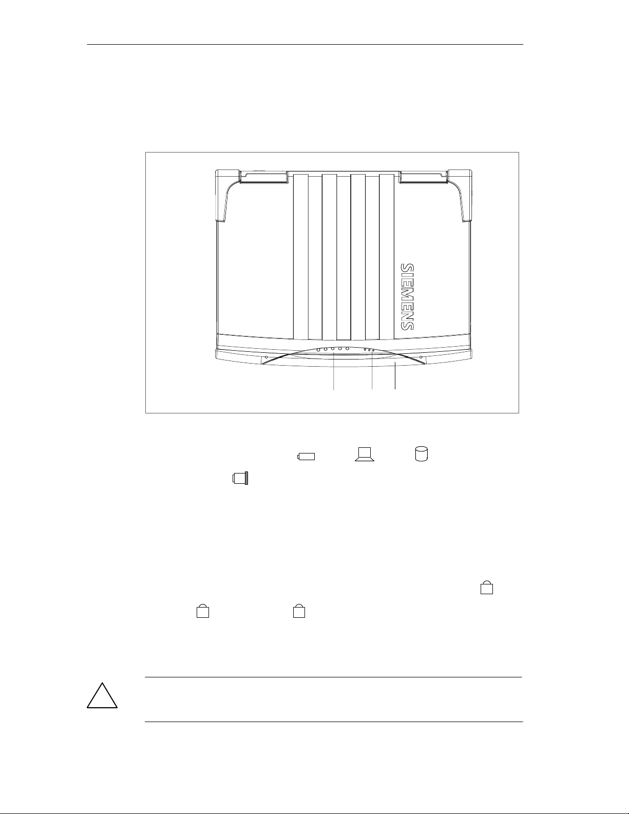
View with closed display
3
1
1 SystemLEDs
The system LEDs (battery status , device
2
On
, drives , MPI/DP
MPI/DP
and Memory Card ) indicate the status of the battery, unit, drives, MPI/DP and
Memory Card interface.
These LEDs are also visible when the display is closed. The drive access displays
are arranged on the right hand side of the corresponding drives.
For detailed information on these LED displays refer to Chapter 2.4 of the
electronic manual.
2 KeyboardLEDs
The keyboard LEDs display the current status of the shift keys Num Lock
Caps Lock
A
and Scroll Lock
. When the unit is booting, the displays of
1
,
these keys flicker briefly. The keyboard is ready for operation.
3 Device Handle
Folding handle for transporting the device.
Caution
!
Always stand the PG on its base. If you place it down on the interface side there is
a risk that it will fall over and that sensitive components of the unit get damaged.
2-2
SIMATIC Field PG Manual
A5E00075760-04
Page 21

Front view with open display
Getting Familiarized with the SIMATIC Field PG
7
1
2
3
4
5
4
7
2
6
1 Display
The Field PG’S 14.1” TFT display has a resolution of 1024 x 768 pixels with up to
256k colors.
2 Stereo Loudspeaker
The speaker outputs audio and system alarm signals generated by the software.
The loudness is adjusted via speaker icon in the task bar or in the Windows Start
menu via Programs > Accessories > Multimedia > Loudness.
3 Keyboard
The keyboard is split into three key areas: the alphanumerical keyboard with
special keys, the function keys and the control keys.
4 Mouse buttons
You can use the left or right mouse button to select menu items or process text or
graphic objects after having marked the respective object.
SIMATIC Field PG Manual
A5E00075760-04
2-3
Page 22
Getting Familiarized with the SIMATIC Field PG
5 Touchpad
The Touchpad has a pressure sensitive surface for precise mouse pointer
positioning.
6 On/Offbutton (Power Button)
Use the On/Off pushbutton to switch on the Field PG (into active state) or to switch
it from active to inactive state (Off, Standby or Hibernate). The Power Button can
be parameterized in Windows. The Windows NT versions do not support this
power management.
7 Display interlock
The display unit is connected to the base unit with two locks. The slide interlock is
mounted at the side of the display unit.
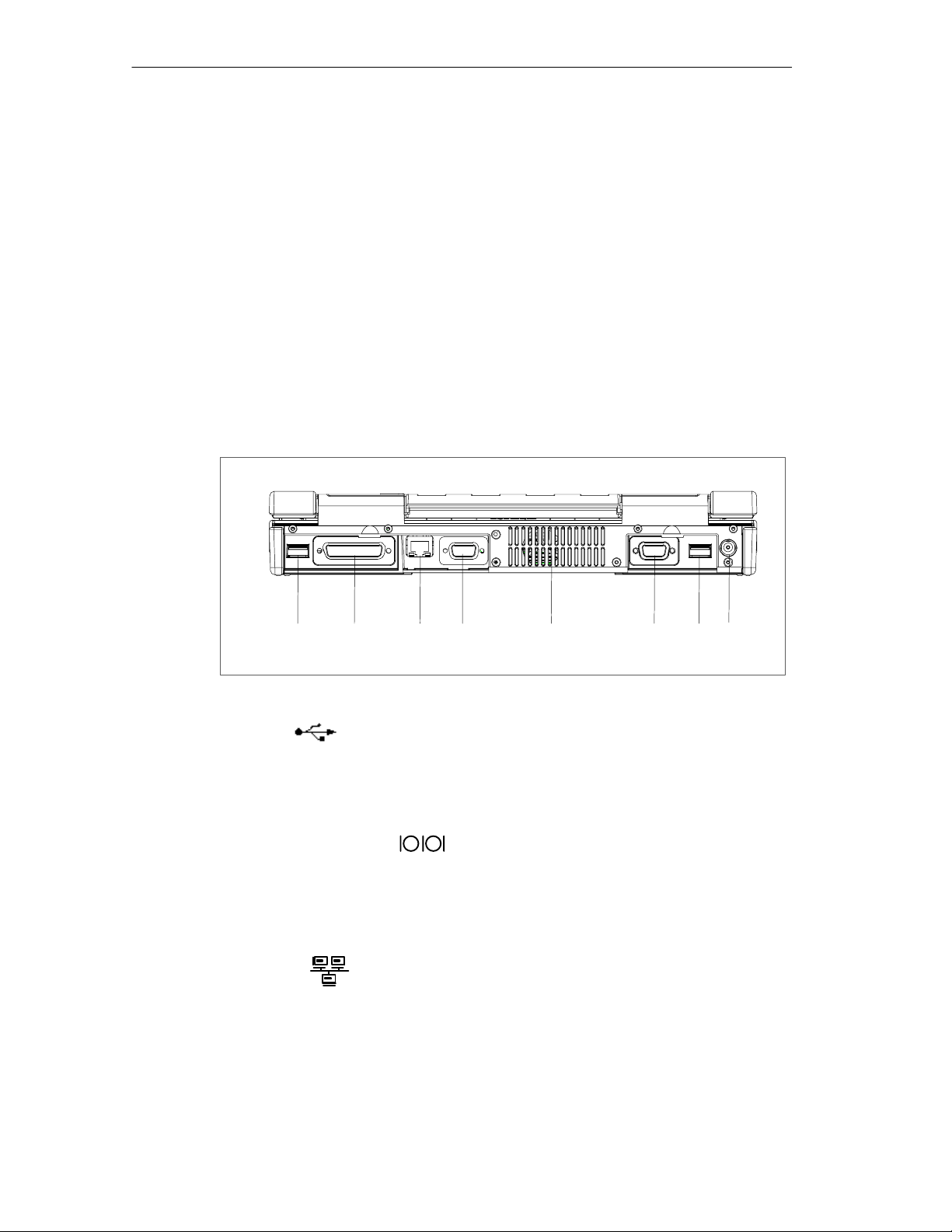
Rear view
1632 5784
1 USB.
Universal Serial Bus connector. You can use the USB port to connect external
devices, for example, CD drives, printers, modems as well as a mouse and
keyboard. The Windows NT versions only support mouse and keyboard.
2 COM1 V.24 /MODEM
/AG
The COM1(TTY) interface is used to connect, for example, S5 programmable
controllers (PLC). The supplied adapter ”Serial Port Adaptors D9/D25” can be used
to convert the interface into a 9-pole standard V.24 interface for connecting serial
interface devices, for example, modems, mice or printers.
3 Ethernet
RJ45 Ethernet connector. Ethernet is a local area network with a bus structure for
data communication with a data transfer rate of 10/100 Mbit per second (Mbps).
4 MPI/DP Multipoint Interface
The MPI/DP interface is isolated from line potential. You can use it to connect the
SIMATIC Field PG to an S7 automation system or to a PROFIBUS network.
2-4
SIMATIC Field PG Manual
A5E00075760-04
Page 23

Getting Familiarized with the SIMATIC Field PG
5 Air venting slots
Here is the ventiduct.
Caution
!
The ventiducts for incoming and outgoing air must not be obstructed. Otherwise,
there is a risk of overheating.
6 VGA
Here you can connect an appropriate external monitor.
Caution
Make sure the monitor can handle the resolution and refresh rate settings. Otherwise, it can result in damage.
7 USB
Second USB port.
8 DCIn 17.5 V
Socket for the DC output plug of the power supply that is included in your
consignment.
SIMATIC Field PG Manual
A5E00075760-04
2-5
Page 24
Getting Familiarized with the SIMATIC Field PG
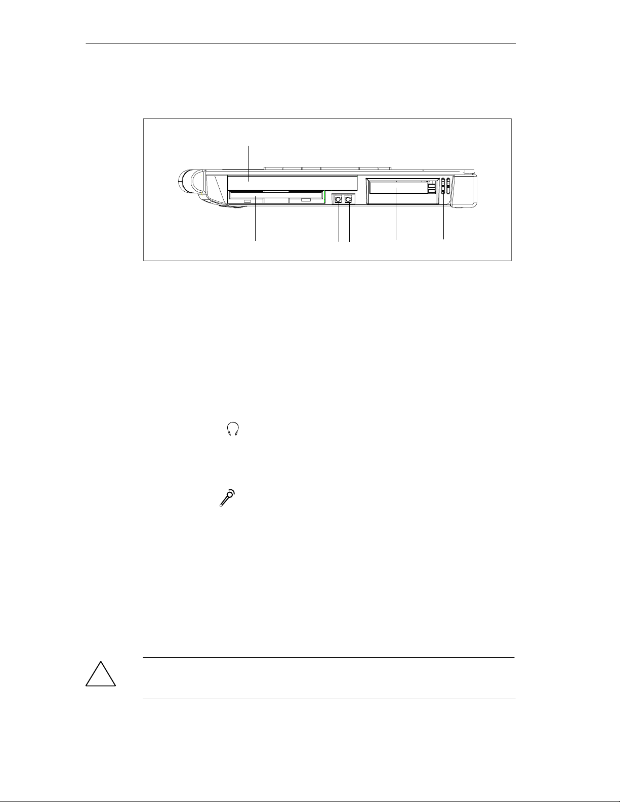
View of the right side
1
54
1 Optical drive
632
Depending on the device configuration, it can come with a CD-ROM, a DVD-ROM
or a DVD-ROM/CD-RW drive. For example, you can read the electronic manual of
the supplied ”Backup PG” CD with this drive.
2 Floppy disk drive
Depending on the device configuration, a standard floppy disk drive (1,44 MB), a
Superdisk LS120 or a Superdisk LS240 drive is built in. 3.5” diskettes (of 1.44 MB)
and Superdisks (up to 120 MB) can be used with the LS120 drive. For LS240,
additional Superdisks up to 240 Mbyte are required.
3 Headphones
You can connect an external stereo headphone or another audio output device to
this headphone jack. The internal speaker is automatically disabled when a
headphone is connected.
4 Microphone
You can connect an external microphone or another audio output device to this
microphone jack.
2-6
5 PCCard slot
The PC-Card slot accepts Cardbus (32 Bit) and PCMCIA (16 bit) cards. You can
plug in credit card-size communication modules for MODEM, FAX-MODEM, ISDN,
Token Ring, ETHERNET, memory expansions and SCSI interfaces. CardBus
Cards are not supported by Windows NT.
6 Air venting slots
Here is the ventiduct.
Caution
!
The ventiducts for incoming and outgoing air must not be obstructed. Otherwise,
there is a risk of overheating.
SIMATIC Field PG Manual
A5E00075760-04
Page 25
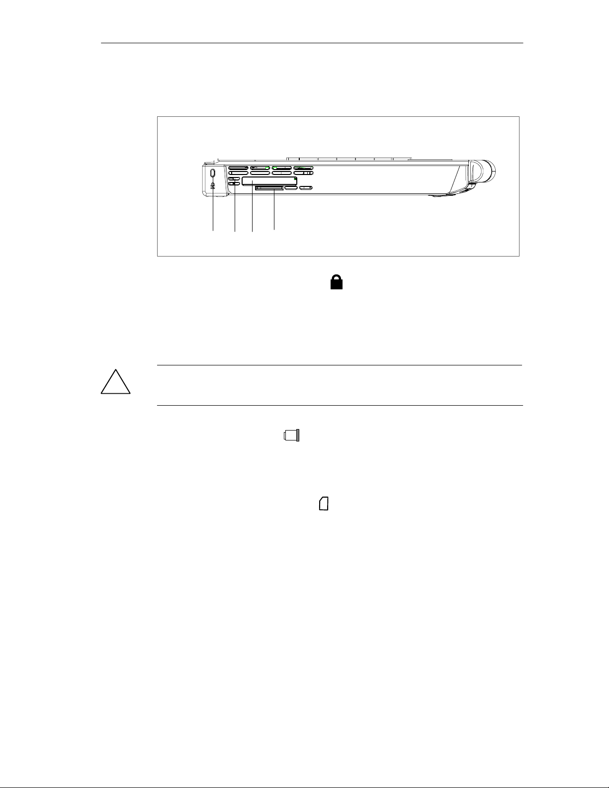
View of the left side
Getting Familiarized with the SIMATIC Field PG
21 43
1 Opening for the Kensington lock
Opening for the connection of a security cable. You can protect your PG against
theft by locking the cable to a writing desk or any other heavy appliance.
2 Air venting slots
Here is the ventiduct.
Caution
!
The ventiducts for incoming and outgoing air must not be obstructed. Otherwise,
there is a risk of overheating.
3 Memory Card interface
Interface for reading, programming or deleting SIMATIC Memory Cards for
SIMATIC S5 and SIMATIC S7. You can also use the supplied S5 adapter to
program or read SIMATIC S5 EPROM submodules.
4 Micro Memory Card interface
This interface can be used to read, program or delete Micro Memory Cards.
K
SIMATIC Field PG Manual
A5E00075760-04
2-7
Page 26
Getting Familiarized with the SIMATIC Field PG
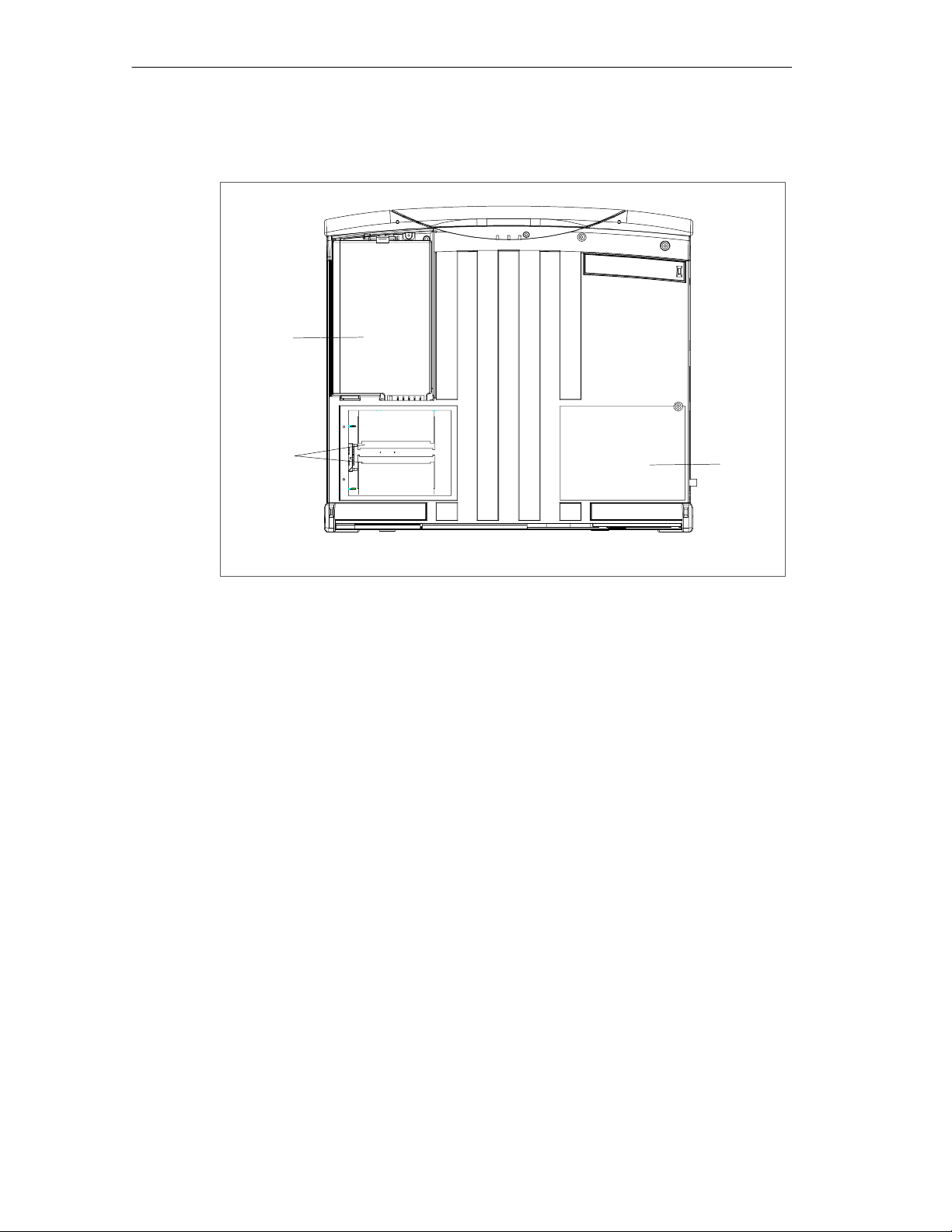
Bottom view
1
2
1 Rechargeable battery
3
The supplied rechargeable battery is installed behind a cover. The rechargeable
battery (Lithium-Ion) makes the device portable, independent of an external power
supply. The battery pack also prevents data loss in case of power failure. See also
section 3.3.
2 Memory expansion
You can install memory submodules in these slots to increase main memory.
Maximum memory expansion: 2 x 256 Mbytes. Remove the cover to access the
memory submodules. See also section 4.1.
3 Rating plate and Certificate of Authenticity
The rating plate and “Certificate of Authenticity” with the Microsoft Windows
“Product Key”. You need this to install new software.
2-8
SIMATIC Field PG Manual
A5E00075760-04
Page 27

2.2 Keyboard
Keyboard Layout
The keyboard is split into the following areas:
• Alphanumeric or typewriter keyboard with special keys
• Function keys
• Cursor control keys.
Repeat Function
All the keys on the keyboard are of the autorepeat type. The character is repeated
as long as the key is pressed.
Keyboard Caps
Getting Familiarized with the SIMATIC Field PG
The keyboard comes with international and German labeling.
International
Shift
Unshift
Fig. 2-1 The Keyboard Labeling System
Alphanumeric Keyboard
The largest block of keys on the keyboard is the alphanumeric keyboard with all
the keys for the letters of the alphabet, numerals and special characters. The
characters are arranged in basically the same way as on a normal typewriter.
However, there are a number of special keys which have special functions for the
SIMATIC Field PG.
?
\
ß
National
Together with
ALT
GR key
U
4
Together with the Fn key:
with Num Lock: 4
without Num Lock: Cursor left
SIMATIC Field PG Manual
A5E00075760-04
2-9
Page 28
Getting Familiarized with the SIMATIC Field PG
Special Keys
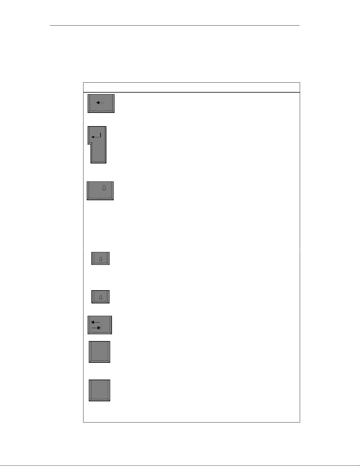
The special keys in the alphanumeric keyboard have the following functions:
Key Function
Backspace key
This key moves the cursor one space to the left and deletes the character at
this position.
Enter Key
(Return, Enter, Line Feed (“New Line”)
Enter
The return or enter key is used mainly to terminate a command line in the
operating system; that is, the command you have entered is executed when
you press this key. For other uses of this key, please refer to the user manual of the relevant user program.
Caps
Lock
Fn
Num
Scroll
CAPS LOCK Key
If you press this key, the middle LED at the top right-hand corner of your
keyboard lights up. All upper case characters and other characters are output normally. If you want to type lower case letters in this position, you must
first press the shift key.
If you are using an international keyboard, you cancel this function by pressing the CAPS LOCK key again. The LED then goes out.
If you have a German keyboard, you must press the shift $ key to cancel
this function.
NUM Key
With these keys Fn+ ^ NUM , the emulated numeric block is switched from
the alphanumeric keyboard to numeric keys. The LED display lights up.
Press this key again to return to cursor control.
Scroll-Lock-Taste
Monitor scrolling is either enabled or disabled with this key.
Tab Key
This moves the cursor depending on the selected tabulator positions.
“Fn” Special Key (combination key)
In conjunction with a second key (key combination), you activate other key
codes for special applications with this key. This key is also used to emulate
the numeric keypad (Figure 2-3 Numeric Keypad).
2-10
Ctrl
CTRL Key (combination key)
This key is only used in combination with other keys. For example, you
press CTRL + ALT + Delete to reset and restart the operating system. For
other uses of this key, please refer to the user manual of the relevant user
program.
SIMATIC Field PG Manual
A5E00075760-04
Page 29
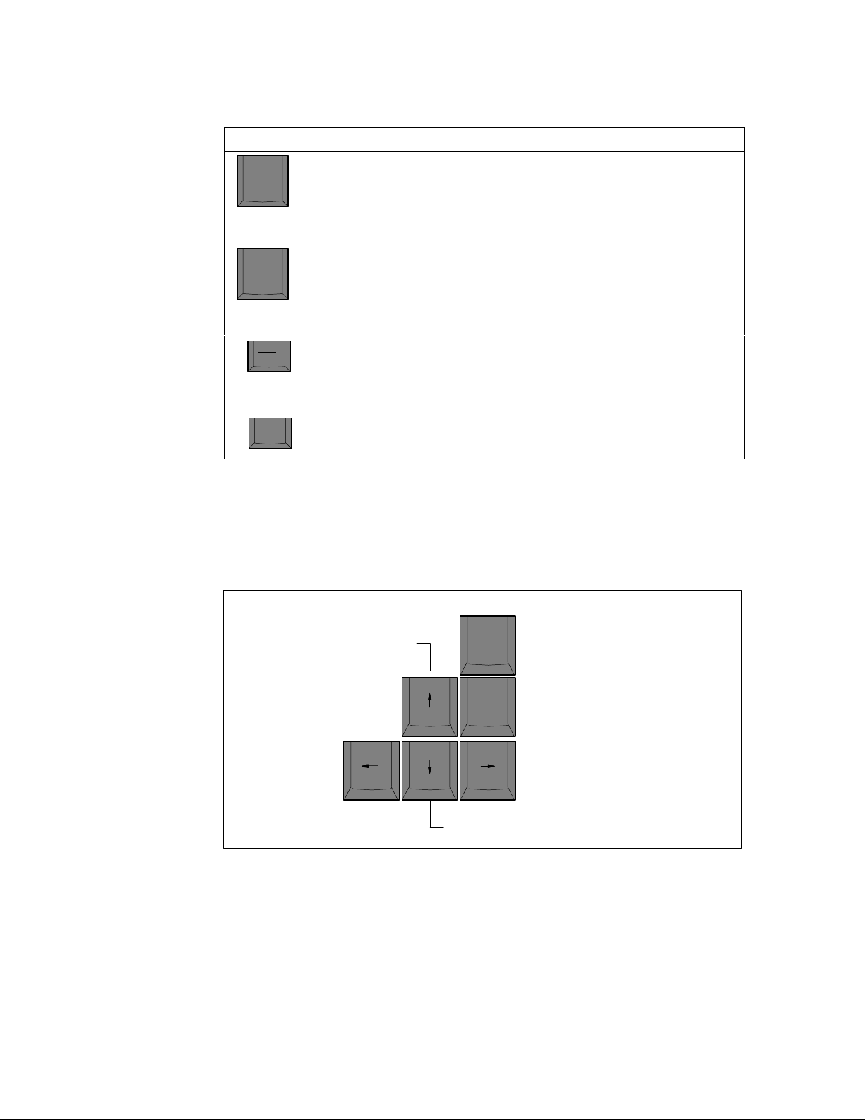
Getting Familiarized with the SIMATIC Field PG
Key Function
ALT Key (combination key)
Alt
Alt Gr
This key is only used in combination with other keys. For example, you can
enter the hexadecimal value of an ASCII character using this key and the
numeric keypad for example, F
ALT
Key (combination key)
Gr
+ ALT + 132 corresponds to “ä .
n
You can use this key together with the other combination keys to generate
other key codes. For example, you can generate the “\” character on the
German keyboard by typing ALT
Gr
+ ß.
Cursor Keys
The key block shown in the picture below is used for cursor control. Home and End
are operated in combination with the Fn key.
Print
SysRq
Pause
Break
PRINT (combination key)
Using the Print key, you can output the current screen display to a printer
(depending on the software used).
PAUSE (combination key)
The Pause key interrupts program execution in the majority of applications.
Cursor up
PgUp
Home
PgDn
End
Page back
Move cursor to beginning of file
Page forward
Move cursor to end of file
Cursor left
Fig. 2-2 Cursor Keys
SIMATIC Field PG Manual
A5E00075760-04
Cursor right
Cursor down
2-11
Page 30
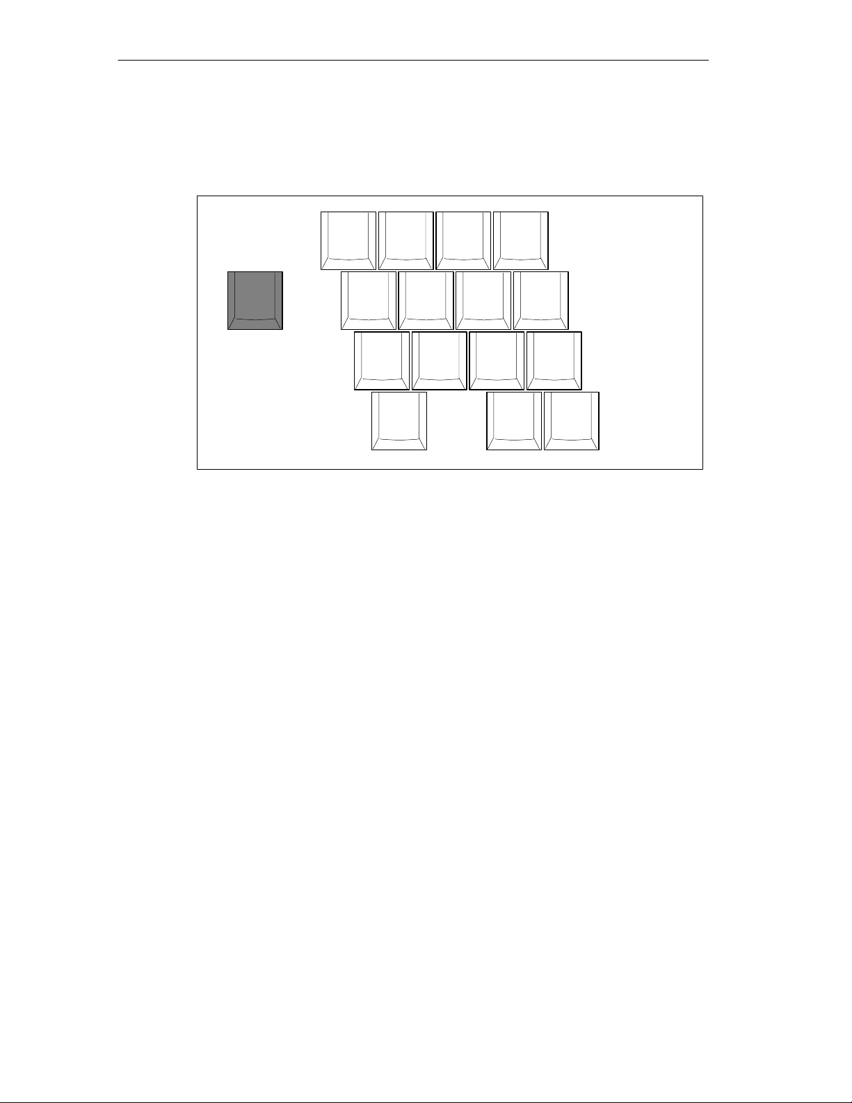
Getting Familiarized with the SIMATIC Field PG
Numeric Keypad with Fn Key
By pressing Fn and one of these keys, the numbers and characters can be used
provided Num Lock is switched on.
Fig. 2-3 Numeric Keypad
Function Keys
A row with twelve programmable Function Keys is located above the alphanumeric
keyboard. The individual function of these keys depends on the software you are
working with.
Fn
& /
7 {
7
+
* (
8 [
8
U
4
J
( )
9 ]
9
I
5
K
) =
0 }
x
O
6
L
P
:Ö
;
1
2
M
0
3
+
> :
? _
.
,
/ –
–
2-12
SIMATIC Field PG Manual
A5E00075760-04
Page 31

2.3 Touchpad
Definition
The Touchpad is an input device for cursor control and menu operation (with
mouse operation) in numerous programs. You can move the cursor to any screen
position by touch.
A left button click on sets the mark. The right button assignment varies, depending
on the user program. You can select objects, process menus or trigger functions
with this Touchpad.
Operation
You can use the Touchpad the very same way as a mouse: the mouse pointer on
the screen follows the movement of your finger on the pad.
You can click on icons or text with both mouse buttons. First, move the mouse
pointer onto the icon. Then, select the icon with a left click.
Getting Familiarized with the SIMATIC Field PG
As an alternative, in a fully graphical user interface, for example, the Windows
GUI, you can mark an icon and then move the mouse pointer on top of it. You can
then open the icon with a double tap on the Touchpad.
You do not have to apply any pressure on the pad with your finger. The sensor
does not react to finger pressure, but rather to the brief capacitance change on the
touch point.
SIMATIC Field PG Manual
A5E00075760-04
2-13
Page 32
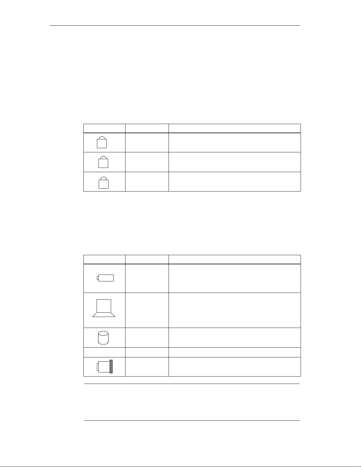
Getting Familiarized with the SIMATIC Field PG
2.4 LED displays
Keyboard LEDs
LED displays for the Num-Lock, Shift-Lock and Scroll-Lock keys. They indicate the
current status of the shift keys.
Meaning of the keyboard LEDs
Symbol LED Meaning
green
1
off
Num-Lockon
Num-Lock off
green
A
off
green
off
System LEDs
The system LEDs (battery, device, drives, MPI/DP and Memory Card) indicate the
status of the battery pack, the unit, the drives as well as the MPI/DP and Memory
Card interfaces. These LEDs are also visible when the display is closed.
Meaning of the System LEDs
Symbol LED Meaning
green
orange
red
off
green
On
orange
green flashing
orange flashing
off
green Access to external storage media (hard disk drive,
Shift-Lock on
Shift-Lock off
Scroll-Lock on
Scroll-Lock off
Battery is charged
Battery is being charged
Battery low (only with battery operation)
No battery installed
Line operation
Battery operation
Line operation, system in Standby mode
Battery operation, system in Standby mode
Unit is switched off
optical drive, floppy disk drive)
2-14
MPI/DP green MPI interface active
green Module programming, Memory Card or
Micro Memory Card active
Note
Battery charging is terminated when the battery pack is fully charged or if, for example, the upper temperature limit is exceeded during charging. The current battery status can be queried in Windows Me/Windows 2000.
SIMATIC Field PG Manual
A5E00075760-04
Page 33

Getting Familiarized with the SIMATIC Field PG
2.5 On/Off Pushbutton (Power Button)
Switching the Field PG On
Hold the On/Off button (Power Button) down for approx. 1 second to switch on the
device.
Switching the Field PG Off
Either close the display lid, actuate the On-/Off-pushbutton (Power Button) or
select the respective Windows Start menu command to toggle the Field PG from
normal mode to one of the following modes:
• Standbymode (Save to RAM),
• Hibernate (Save to Disk),
• Off (Windows is shut down).
If operated under a Windows OS the device is switched off automatically when you
shut it down. If not operated under Windows you can switch the device off via
On-/Off pushbutton.
Notice
The Windows NT versions do not support the standby and hibernate operating
modes. After shut down the Field PG always has to be switched off via the Power
Button.
Hold down the On-/Off pushbutton for more than 7 seconds to trigger the
“Override” function. The device is switched off.
Note
Via Setup > Control Panel > Power Management under Windows Me and Windows 2000 you can parameterize the reaction of the On-/Off-pushbutton and of
the display lid.
To isolate the unit totally from the power supply system, you must unplug the patch
cord and remove the rechargeable battery.
SIMATIC Field PG Manual
A5E00075760-04
2-15
Page 34

Getting Familiarized with the SIMATIC Field PG
Caution
The Field PG supports different operating modes, according to the settings in the
Windows power options. The power options are preset at the factory in such a way
that the device always switches to defined operating modes (On, Standby, Hibernate, Off).
When changing these settings or updating the device with additional hardware (for
example, USB components) or additional software, the operating modes can be
influenced in such a way that the device can no longer switch to the hibernate or
standby mode. Although the screen is dark, relevant components remain active
and consume power.
Before transporting the Field PG in the carrying case, always shut it down or set it
to hibernate mode. You can recognize these modes when all status LEDs are switched off after the power supply has been disconnected. By doing this you can be
sure that the device is not switched on during transport and that the battery is not
unintentionally discharged.
Energy Options
You can optimize the energy consumption of your PG using the energy options
while maintaining the PG in operate state.
In Standby mode the screen and the hard disk drive are switched off to relieve the
battery pack. After you switch the PG back to normal mode the desktop is restored
with your last configuration. Since PG memory information is not written to the hard
disk drive, you should save your job before you switch the PG to standby mode.
Information stored in memory is lost in case of a power failure.
Note
Select this mode if you briefly interrupt your work (few hours).
In Hybernate mode the screen and hard disk drive are switched off. All data in
memory is stored to the hard disk drive before the PG is switched off. When you
switch on your PG again, all programs and documents that were opened at the
time of shut-down are restored to the desktop. Hybernate mode relieves the
battery pack even more than Standby mode. However, it requires a longer time to
reactivate the PG from this hybernating state.
Note
Select this setting if you want to interrupt your work over an extended period (several hours) or over night.
2-16
Briefly push the On/Off button to reactivate the PG from Standby or hybernate
mode. In standby mode the system LED flashes, in hybernate mode all displays
are switched off.
SIMATIC Field PG Manual
A5E00075760-04
Page 35

2.6 Drives
2.6.1 Floppy Disk Drive
Depending on the device configuration, a standard floppy disk drive (1,44 MB), a
Superdisk LS120 or a Superdisk LS240 drive is built in. 3.5” diskettes (of 1.44 MB)
and Superdisks (up to 120 MB) can be used with the LS120 drive. For LS240,
additional Superdisks up to 240 Mbyte are required.
Types of Diskette
You can use the following diskettes:
Getting Familiarized with the SIMATIC Field PG
3.5 inch
1.44 Mbytes (135 TPI)
3.5 inch
120 Mbytes
3.5 inch
240 Mbytes
Handling Diskettes
Access to the floppy drive is displayed by the drive’s status indicator and on the
status indicator for external devices at the front of the keyboard.
Caution
Risk of data loss!
Do not remove diskette until the access indicator on the drive has been switched
off.
Standard
Floppy Disk Drive
–
– –
LS120 LS240
Emergency Removal bei LS120/LS240 Disk Drive
When the device is switched off, the disk can be forced out by using a pin
(for example, a bent paper clip).
SIMATIC Field PG Manual
A5E00075760-04
2-17
Page 36

Getting Familiarized with the SIMATIC Field PG
Information on the LS120/LS240 Disk Drive
Restrictions
P-Tools under STEP 5
Data cannot be edited in PCP/M format on the LS120/LS240 drive using P Tools
under STEP 5.
Notice
When you use the P Tools (for editing PCP/M files) supplied with STEP 5,
remember that these are not fully supported by the Windows Me and
Windows 2000 operating systems nor by LS120/LS240 diskette drives. If you use
the P Tools, we recommend that you use MS-DOS, Windows 3.x or Windows 95
and standard 1.44 Mbyte floppies.
Authorization with Authors W V2.x
To authorize STEP 7 and other SIMATIC components you must use AuthorsW.
Start this program on the PG via the taskbar under Start > Simatic > AuthorsW.
Usage Notes for LS120/LS240 Superdisks
The LS120/LS240 drive automatically recognizes the different floppy disk types.
Due to their higher storage capacity, Superdisks are more sensitive to dirt,
temperature and shock than conventional disks.
Notice
In order to achieve a reliable operation and high data security, please note the
following during use:
• Store and transport the Superdisk in the protective cassette included to keep
dust and dirt from the disk.
• Remove Superdisk from the drive when it is not being read or written to keep
dirt particles away from the disk. Do not expose the disk unnecessarily to high
operating temperatures.
Notice
If possible avoid vibration of the device, when using Superdisks. Superdisks are
more sensitive to vibration as a result of their high track density.
2-18
SIMATIC Field PG Manual
A5E00075760-04
Page 37

2.6.2 Hard Disk Drive
A variety of hard disk drives can be operated with the SIMATIC Field PG.
Whenever the hard disk is accessed, the status LED for external storage media at
the keyboard front lights up.
Caution
Drives are sensitive to vibrations and shock. Any vibrations occurring during operation can result in loss of data or damage the drive.
2.6.3 Optical Drive
Depending on the device configuration, it can come with a CD-ROM, a DVD-ROM
or a DVD-ROM/CD-RW drive. For example, you can read the electronic manual of
the supplied ”Backup PG” CD with this drive.
Getting Familiarized with the SIMATIC Field PG
Opening the Drawer
Switch on the programming device. By briefly pressing the eject button, the drawer
springs out slightly. Now pull the drawer out until it clicks into position.
Inserting / Removing CDs
Now insert the CD in the drawer with the labeling face up, and press it firmly down
into the center of the turntable. To remove the CD, hold it by the edges and pull
upwards.
Closing the Drawer
Push in the drawer until it closes completely. Do not press the eject button.
Emergency removal
By pushing a pin into the emergency release opening (for example, a paper clip)
while the device is switched off, you can force the drawer to open.
SIMATIC Field PG Manual
A5E00075760-04
2-19
Page 38

Getting Familiarized with the SIMATIC Field PG
Notice
To ensure that the open drawer of the CD-ROM drive is not exposed to excessive
force, always support the front of the drawer with one hand while inserting or removing the CD-ROM with the other.
The CD is tested when you close the drive and the access LED on the drive flashes to indicate that the test is in progress:
– if the LED does not stop flashing the CD is bad but readable,
– if the LED flashes several times and then remains on, the CD is not readable and
defective.
Caution
Risk of data loss and damage to the drive.
Optical drives are highly sensitive to excessive vibration. Vibration during opera-
tion can damage the drive or the CD.
Use the DVD-ROM/CD-ROM drive for a burning operation in untroubled environ-
ment only.
Additional Software
To be attain the full functionality of the DVD-ROM or DVD-ROM/CD-RW drive,
additional software (DVD player or burner software) is necessary. You can find it on
the CD included in the delivery of the device. To install the software place the CD
in the drive and follow the instructions on the screen.
2-20
SIMATIC Field PG Manual
A5E00075760-04
Page 39

Getting Familiarized with the SIMATIC Field PG
2.7 External Power Unit and Battery
External Power Unit
External power supply for the SIMATIC Field PG for operation on 120 V or 230 V
power supply networks. The voltage range is selected automatically. With line
operation the integrated battery is charged at the same time. The connecting cable
for the SIMATIC Field PG is installed fixed on the external power supply. The
external power supply is connected with a patch cord to the mains.
Warning
!
The SIMATIC Field PG must only be operated with the correct external power supply and/or battery enclosed with the device.
The external power supply must not be covered up (risk of overheating).
Notice
The power plug must be disconnected to isolate the unit completely from mains.
A CSA or UL-listed cord set must be used for operation in Canada and the USA.
For the United States and Canada:
In the United States and Canada the cord must be UL-listed and CSA Labeled.
The male plug is a NEMA 5-15 style.
For operation with 120 V:
Use a UL-listed, CSA Labeled Cord Set, consisting of a min. 18 AWG. Type SVT
or SJT three conductor flexible cord, max. 4.5 m (15 feet) in length and a parallel
blade grounding type attachment plug, rated 15 A, min 125 V.
For operation with 240 V (within the USA):
Use a UL-listed, CSA Labeled Cord Set, consisting of a min. 18 AWG. Type SVT
or SJT three conductor flexible cord, max. 4.5 m (15 feet) in length and a tandem
blade grounding type attachment plug, rated 15 A, 250 V.
For operation with 230 V (outside of USA):
Use a cord set consisting of a min 18 AWG cord and grounding type attachment
plug rated 15 A, 250 V. The cord set should have the appropriate safety approvals
and marks for the country in which the equipment will be installed.
The unit is intended for operation with grounded power supply networks
(TN networks, VDE 0100 part 300 or IEC 364-3).
Operation with non-grounded or impedance-grounded networks (IT networks) is
not permitted.
The cord set must meet safety requirements in the respective country.
SIMATIC Field PG Manual
A5E00075760-04
2-21
Page 40

Getting Familiarized with the SIMATIC Field PG
Battery
The included battery pack is installed underneath a cover. The Field PG has an
integrated (Lithium-Ion) rechargeable battery. This makes the device portable,
meaning you can use it without the external power supply. The battery also
prevents data loss as a result of power failure.
Once the external power supply unit is connected, the battery is charged. The
following conditions are important:
• When the device is switched off, charging takes approximately 3 hours (fast
charging).
• When the device is switched on, charging takes approximately 3 to 6 hours
(depends on the system load).
• Charging stops as soon as the battery is fully charged.
• A fully charged battery that is put on shelf runs down within approximately 2 to
4 months (depending on the temperature and whether it is installed). It must
then be recharged.
• You can check the battery status in Windows. See also Section 3.3 Battery
Mode.
• It is advisable to run a teach-in cycle every now and again
(see Section 3.3).
When the unit is connected to the power supply, the green battery LED indicates
that the battery is fully charged. Battery charging is then stopped.
Notice
When not used over an extended period (weeks), switch off the Field PG and remove the battery (see Section 3.3).
The red battery LED and an acoustic warning sounds to warn of pending total discharge (see Section 3.3)
Please note that you must disconnect the power cord to separate the device totally
from mains.
You can check the battery status directly on the battery pack. Press the marked
spot on the battery briefly. The status is then displayed by the four LEDs.
Warning
!
– Do not disassemble or mutilate, may cause burns.
– Do not incinerate or heat, may cause burns, exposion or release toxic materials.
2-22
– Do not short circuit, may cause burns.
– Keep away from children.
SIMATIC Field PG Manual
A5E00075760-04
Page 41

Configuring And Operating The SIMATIC Field PG
What Does This Chapter Contain?
The chapter below describes all tasks required to successfully set up your
workplace. These include:
• initial steps for commissioning your SIMATIC Field PG,
• working with battery operation and replacing the battery,
• connecting peripheral devices,
• working with memory submodules for the PLC and
• connecting your PG to other devices.
Chapter Overview
Section Description Page
3.1 Unpacking and Setting Up the SIMATIC Field PG 3-2
3.2 Connection to the Power Supply 3-4
3.3 Battery Operation 3-5
3.4 Commissioning 3-8
3.5 Panel “Field PG” 3-11
3.6 Connecting Peripheral Devices 3-12
3.7 Working with SIMATIC-S5 memory submodules 3-15
3.8 Working with SIMATIC Memory Cards 3-16
3.9 Working with Micro Memory Cards 3-17
3.10 Working with PC Cards 3-18
3.11 Connecting the Field PG to a SIMATIC S5 Network 3-19
3.12 Connecting the Field PG to a SIMATIC S7 Network (MPI/DP) 3-20
3.13 Networking the Field PG with Other Stations on PROFIBUS 3-22
3.14 Ethernet (RJ45 Ethernet Interface) 3-22
3
Warning
!
SIMATIC Field PG Manual
A5E00075760-04
When connecting long signal lines (especially for plant-wide connections), make
sure that the signal lines are connected to the local equipotential grounding system
(cable shield connected to protective conductor).
3-1
Page 42

Configuring And Operating The SIMATIC Field PG
3.1 Unpacking and Setting Up the SIMATIC Field PG
Unpacking Your SIMATIC Field PG
Unpack your SIMATIC Field PG as follows:
1. Remove the packing.
2. Do not throw the original packing away. Keep it if you need to transport the
device at a later time.
Checking the Contents
3. Check the packing list to make sure that no components are missing
4. Check the packing and its contents for any transport damages.
5. Please inform your local dealer of any shipping damages and discrepancies
between contents and packing list.
Entering the Serial number (F-No.) and the Ethernet address
6. Enter the serial number and the Ethernet address of your programming
device in the table below. You can find the serial number on the type label
attached to the base of the device. The Ethernet address can be found in the
BIOS setup settings in the main menu under the ’Hardware Options’ function.
If the device has to be repaired or has been stolen, it can easily be identified by
these numbers.
Entering the Microsoft Windows “Product Key” from the “Certificate of
Authenticity”
7. Enter the Microsoft Windows “Product Key” from the “Certificate of Authenticity”
(COA) in the table. You will find the “Product Key” on the device. You need the
Windows “Product Key” if you want to reinstall the operating system.
F-No.
Order No.
Microsoft Windows Product Key
Ethernet Address
3-2
SIMATIC Field PG Manual
A5E00075760-04
Page 43
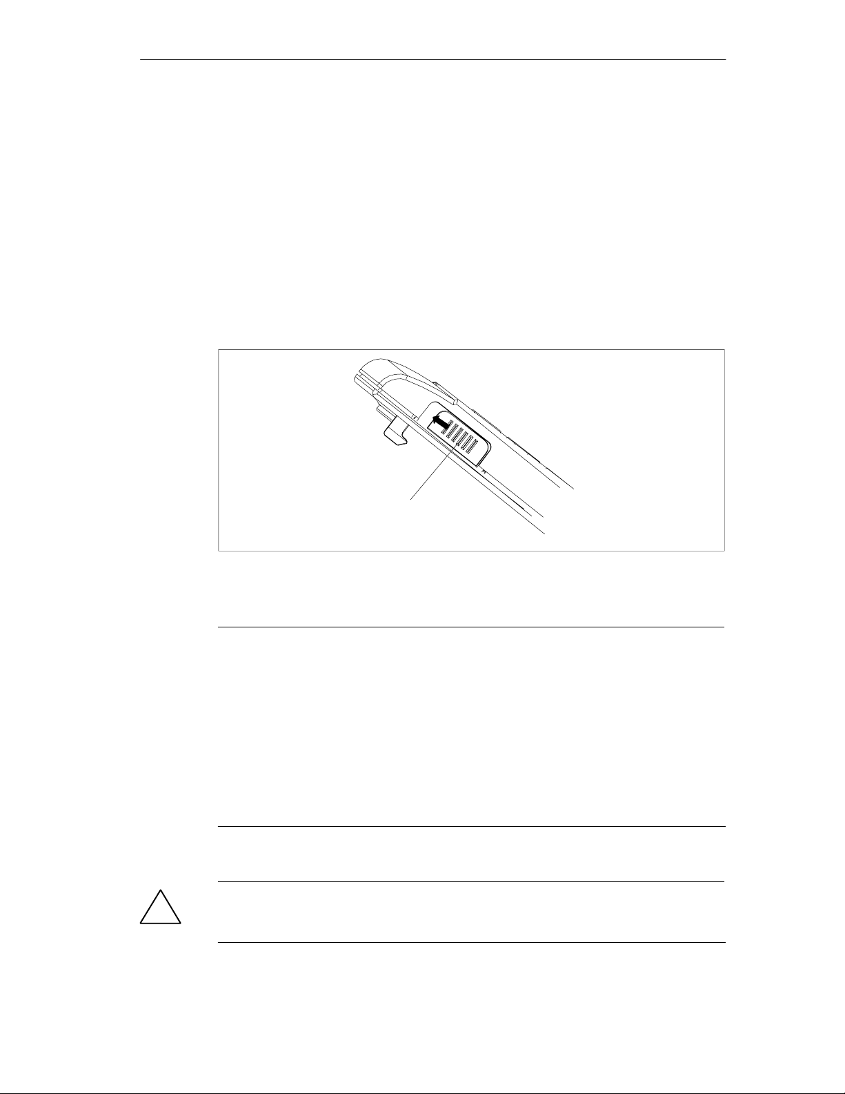
Setting up your SIMATIC Field PG
Find a comfortable and safe working position for your SIMATIC Field PG.
1. Put the SIMATIC Field PG down on its base on an even surface at a
comfortable working height and distance.
2. Ensure there is an easily accessible mains outlet near your place of work.
3. Make sufficient desk space available to connect peripheral devices.
4. Open the display, by pulling the slide locks at the side of the display unit
towards the front.
5. Fold up the display and adjust it to a comfortable angle of inclination. The
display angle is adjustable from 0 ... 180.
Configuring And Operating The SIMATIC Field PG
Display lock
Fig. 3-1 Opening the Display
Caution
Always put the Field PG down on its base. If you put it down on its interface side
you risk that it will fall over and damage sensitive internal components.
Moisture ingress can damage the PG.
If you transport the device in cold weather and if it is exposed to extreme tempera-
ture fluctuation you have to acclimatize it to room temperature before you start to
operate it.
Do not switch on the device until inside condensation has dried off completely.
This is the case, for example, with a temperature rise from -20 °C to + 20 °C and
after a waiting period of approx. 12 hours.
Warning
!
The computer casing is made of magnesium. Contact with an external open fire
source bears the risk of fire / spreading fire.
SIMATIC Field PG Manual
A5E00075760-04
3-3
Page 44
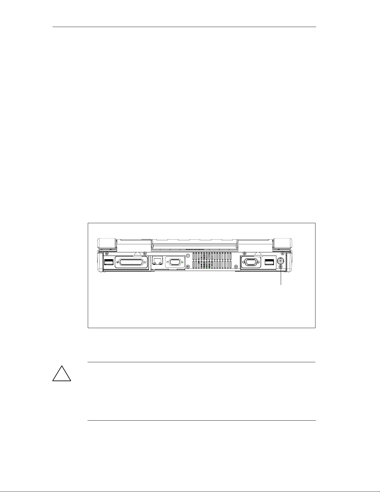
Configuring And Operating The SIMATIC Field PG
3.2 Connecting to the Power Supply
Connecting to the Power Supply
The SIMATIC Field PG can be operated with the supplied external AC adapter
on 120 V/230 V power systems or with the battery. The external power supply
automatically selects the voltage. You should install the supplied battery pack
before you connect the device to the power supply:
1. Turn the Field PG over and place it down on the table while the display unit is
closed.
2. Unlock and open the battery pack cover on the bottom of the device.
3. Insert the battery pack.
4. Close the cover and turn the device over again.
5. Plug the supplied patch cord into the external power supply and plug the
low-voltage plug into the unit’s connector.
6. Connect the external power supply to a socket outlet with grounded protective
conductor.
Connector for an external power supply
VN = 17.5 V DC
Fig. 3-2 Power supply connection
Warning
!
The SIMATIC Field PG must only be operated with the provided power supply unit
and/or battery pack.
The external power supply must not be covered up (risk of over-heating).
For reasons of safety you must use the patch cord and power supply that is inclu-
ded in the delivery. Operation of the unit is only permitted on grounded 120V/230V
power supply networks.
3-4
SIMATIC Field PG Manual
A5E00075760-04
Page 45

3.3 Battery Operation
Battery Operation
If not connected to an external power supply unit, the SIMATIC Field PG can be
operated with the internal battery pack.
1. Switch on the device. Make sure the battery is sufficiently charged before you
start work.
2. Work as usual with your SIMATIC Field PG.
3. In battery mode, the red signal of the battery LED indicates that the battery is in
low condition. Stop your work and save your data. There are only a few minutes
of battery operation remaining.
Notice
Do not start a work session in battery mode unless the battery is fully charged. This
is the only way of ensuring that the full on-battery operating time is available and that
you will be warned in good time when battery power is low. When connected to the
external power supply unit, the orange battery LED indicates that the battery is being
charged.
Configuring And Operating The SIMATIC Field PG
When connected to the external power supply unit, the green battery LED indicates
that the battery is fully charged and that charging has stopped.
The battery might be partially or totally discharged when you start commissioning (fro
example, running-down). Connect the device to the power supply unit and the unit to
mains to charge the battery.
As soon as the device is connected to mains via the power supply unit, the battery
is recharged.
Replacing the Battery
You can replace a run-down or defective battery with a new replacement battery:
1. Turn the Field PG over and place it with closed display unit onto a flat mat.
2. Unlock and open the battery cover on the bottom of the casing.
3. Replace the battery.
4. Close the cover and turn the device over again.
Warning
!
Do not use a battery type other than that supplied. The battery is available as
spare part. Refer to the catalog for ordering data.
SIMATIC Field PG Manual
A5E00075760-04
3-5
Page 46

Configuring And Operating The SIMATIC Field PG
Disposal of Used Batteries
Lithium-Ion batteries can be recycled. Their components can be used as raw
materials for new batteries or other products. Effective recycling of batteries is only
possible when the used batteries are collected according to type.
Notice
Observe the local regulations for disposal of recycling materials.
Charge-Status Indicator
The battery has electronic circuitry for showing the current charge status. The
electronics incorporate a metering unit which has to be calibrated at regular
intervals so that it can compensate for error. The chemical properties of the battery
change in the course of time, so the electronics have to relearn the battery’s
characteristics at regular intervals. A teach-in cycle ensures that the battery’s
maximum charge capacity is at your disposal.
Notice
There is a danger of the charge-status indicator misinterpreting the actual capacity
of the battery if a lengthy period of time is allowed to pass between teach-in cycles. This can result in an unexpected shutdown with no prior warning.
Teach-in Cycle (calibration cycle)
Run a teach-in cycle:
• Approximately every six months,
• if a prolonged period of time has elapsed since the battery was last used,
• if you think that the battery no longer operates at full capacity,
• if the programming device shuts down unexpectedly with no prior warning,
• if operating time on battery becomes shorter.
3-6
SIMATIC Field PG Manual
A5E00075760-04
Page 47

Performing a Teach-in Cycle
Broadly speaking, the procedure for a teach-in cycle is as follows:
1. Power supply operation: Charge the battery until it is full (battery display on
the device is green). Duration: About 3 hours for an empty battery.
2. Battery operation: Discharge the battery until the battery display on the device
changes from orange to red. To do this, remove the power supply unit from the
Field PG.
Duration: approximately 2–4 hours.
3. Power supply operation: Charge the battery for about 30 minutes; to do this
connect the power supply unit again.
You can carry out an automatic teach-in cycle with the “Field PG” panel (see
section 3.5).
Configuring And Operating The SIMATIC Field PG
SIMATIC Field PG Manual
A5E00075760-04
3-7
Page 48

Configuring And Operating The SIMATIC Field PG
3.4 Commissioning
Switching on the Field PG
The operating system and system software supplied with the SIMATIC Field PG
are preinstalled on the hard disk. Time consuming installation of the operating
system and SIMATIC software programs is not required. Just unpack and power
up your unit and you can immediately start your programming tasks without having
to take extensive setup actions.
• To power up the device hold down the On/Off switch for on the top side of the
keybord for at least one second. When powering up the device you have to
distinguish between the following:
– Initial start to set up the Field PG’s software and a
– Restart after cold start and authorization.
3.4.1 Cold Start of the SIMATIC Field PG
When powering up the SIMATIC Field PG for the first time the operating system is
set up automatically (depending on the version delivered: Windows Me,
Windows NT or Windows 2000 Professional). Please proceed as follows:
1. Switch on the Field PG.
2. The PG executes a self-test. During self-test the following message appears on
the screen:
Press <F2> to enter SETUP
Wait until the message disappears and follow the instructions displayed on the
screen.
3. Enter your product key. The product key can be found on the device in the line
“Product Key” of the “Certificate of Authenticity”.
Caution
Do not switch off the PG during cold start. Otherwise, full initialization will fail.
Do not change the BIOS default values.
Startup under Windows
3-8
Once you have entered the requisite information and configured the operating
system the PG is rebooted. The Welcome screen helps you to get familiar with
the Desktop - user interface.
Now the user interface is displayed following system startup every time you power
up or reset the PG.
SIMATIC Field PG Manual
A5E00075760-04
Page 49

Default country code of the Windows 2000 menus, dialogs and keyboard layout is
English. You can set another language and keyboard via the control panel with the
dialog Start >Settings > Control Panel > Regional Options > tab ”General”,
box ”Menus and dialogs”> tab ”Input locales”, box ”Input language”.
Authorization
To use the SIMATIC software e.g. STEP 7 you have to install an authorization,
since it is not possible to run this protected software without authorization. The
authorizations can be found on the Authorization disk that comes with your PG.
To perform the authorization:
• Insert the authorization disk in drive A:
• Click on the Windows ”Start” button and
• select the menu command Simatic > AuthorsW > AuthorsW to open the
Configuring And Operating The SIMATIC Field PG
authorization tool. It will guide you through the installation routine of the
authorization. Copy the STEP 5 and STEP 7 authorization by selecting “All“.
Notice
The authorization diskette supplied with the PG contains authorizations for the SIMATIC software you ordered only. The SIMATIC software you receive will correspond to your order form.
The diskette of the supplied version ”Upgrade Installation” contains only the software for upgrading authorizations already preinstalled.
Software without authorizations in the in the scope of supply cannot be used when
installed on the PG.
Keep the Authorization disk in a safe place so that you can save the authorizations
to disk.
Additional software
You can now install the the supplied operating software for the DVD-ROM or the
DVD-ROM/CD-RW drive. Place the CD in the drive and follow the instructions on
the screen
SIMATIC Field PG Manual
A5E00075760-04
3-9
Page 50

Configuring And Operating The SIMATIC Field PG
3.4.2 Restart of the SIMATIC Field PG
Once the Field PG is configured, the user interface of the corresponding operating
system is displayed following system startup every time you switch on or reset the
PG.
Starting SIMATIC Software Programs
STEP 5 (not available on all delivered versions)
• Click ”Start” on the Windows button and select the desired program choosing
Simatic > STEP 5.
Please note that you have to install the authorization disk before you start
working with STEP 5 (see Section 3.4.1).
Notice
When you use the P Tools (for editing PCP/M files) supplied with STEP 5, remember that these are not fully supported by the Windows Me and Windows 2000 operating systems nor by LS120/LS240 diskette drives. If you use the P Tools, we
recommend that you use MS-DOS, Windows 3.x or Windows 95 and standard
1.44 MB floppies.
STEP 7
• Click on the icon “SIMATIC Manager” on the Windows desktop or
• or click on “Start” and select the desired program by choosing Simatic >
STEP 7.
Note
The transfer of a STEP 7 configuration from on PG to another is supported by the
STEP 7 file archiving functions. Open the SIMATIC Manager. select the menu
command File > Archive or File > Retrieve. You can find details on this proce-
dure in the STEP 7 online help, section “Steps to take for Archiving/Retrieving”.
STEP 7-Micro/WIN 32
• Click on the On the ”STEP7-MicroWIN“ icon on the Windows Desktop or
• Click ”Start” on the Windows task bar and select the desired program with
Simatic > STEP 7-MicroWIN 32.
3-10
SIMATIC Field PG Manual
A5E00075760-04
Page 51

3.5 Panel “Field PG”
Panel “Field PG” helps you to work better with the Field PG. It has the following
functions:
• Automatic execution of battery calibration.
• Setting the display brightness
• Temperature display
• Hardware properties of the PC Card, MPI and Ethernet interface
• Display of firmware versions
The Panel is installed on devices with Windows Me and Windows 2000.
• Start the program via Start > Settings> Control panel> Field PG.
You can find additional support during operation in the respective Online Help.
Configuring And Operating The SIMATIC Field PG
SIMATIC Field PG Manual
A5E00075760-04
3-11
Page 52
Configuring And Operating The SIMATIC Field PG
3.6 Connecting Peripheral Devices
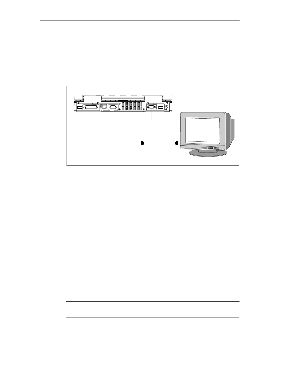
Connecting External Monitors
You must switch the PG off before you connect the monitor cable. You will find
further information about the connector pin assignment in Chapter 7.
VGA socket
Fig. 3-3 Connecting the Monitor
To connect the monitor, proceed as follows:
1. Switch off the SIMATIC Field PG and the monitor.
2. Open the port cover on the rear of the device.
3. Plug the monitor cable into the VGA socket connector.
4. Secure the connector with the screws.
5. Plug the other end of the monitor cable into the monitor.
6. Switch on the SIMATIC Field PG and the monitor.
7. Make the necessary changes in the SETUP program (Menu > Main >
Hardware Options “CRT enabled”, “LCD enabled” “SIMULTANEOUS”).
Note
Default setting is simultaneous operation of the flat screen display and of an external
monitor. The display unit is optimized for a format of 1024*768 pixels. Modes with lower resolution and text mode are expanded to this format.
You can optimize the external monitor display via BIOS Setup in the Main menu item
Hardware Options or the setting ”CRT/LCD selection: CRT enabled”.
3-12
Caution
Ensure that the used monitor is suitable for the set resolution and refresh rate.
SIMATIC Field PG Manual
A5E00075760-04
Page 53
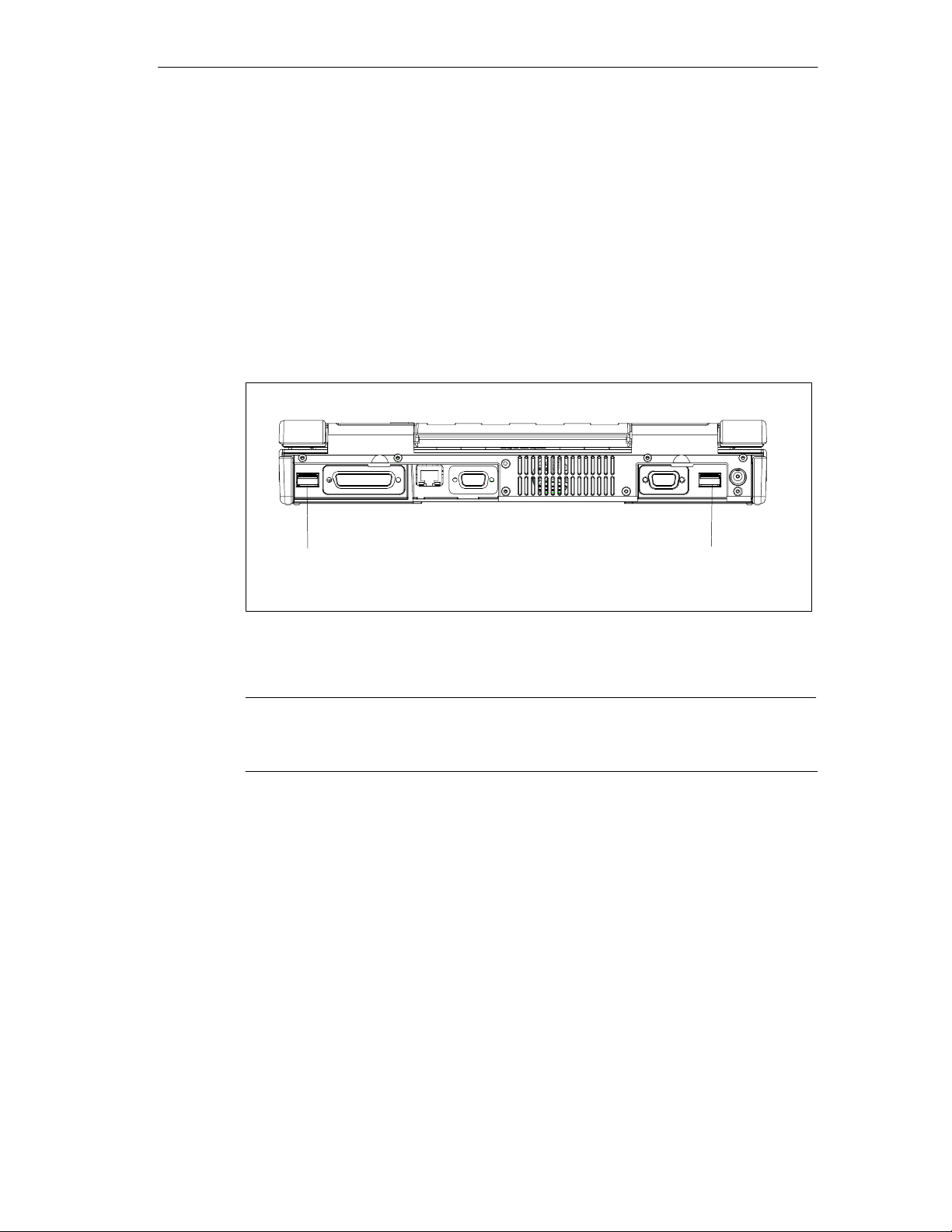
Connecting Devices to the USB Interface
You can connect single or multiple USB devices (mouse, keyboard or printer) to
one USB interface connector.
1. Open the port cover on the rear of the device.
2. Plug the USB device cable into the USB interface.
The Plug and Play operating system recognizes the device and makes it available.
If you wish to connect more than two USB devices you must use a HUB. Only one
of the interfaces can be used as high-current source (refer to the Appendix B,
Technical Data).
Configuring And Operating The SIMATIC Field PG
Fig. 3-4 USB connectors
Note
Devices that do not have a USB plug (for example, printers) can be connected to
the USB interface via adapter.
Using a Mouse
You can connect a USB mouse parallel to the Touchpad.
USB connector
USB connector
SIMATIC Field PG Manual
A5E00075760-04
3-13
Page 54
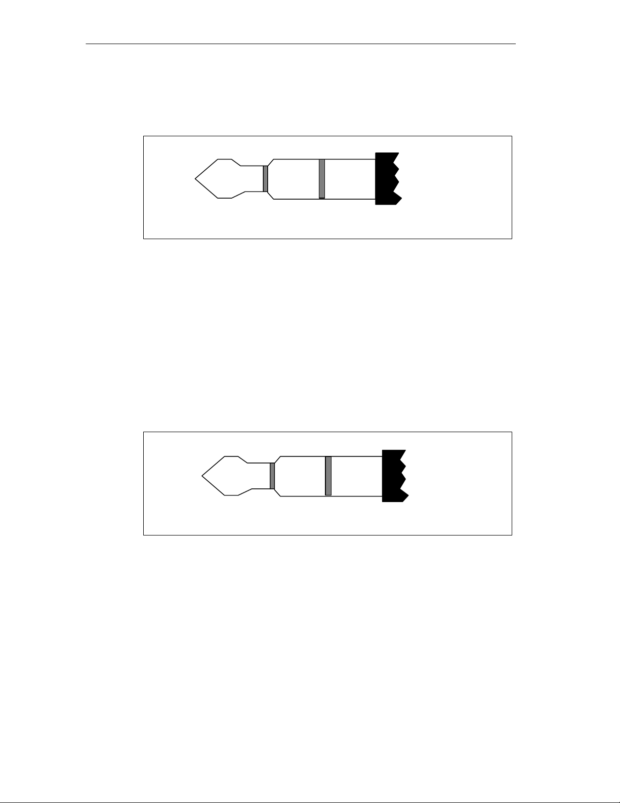
Configuring And Operating The SIMATIC Field PG
Connecting a Microphone
The 3.5-mm phono jack can be used to connect microphones. Pin assignment:
Fig. 3-5 Pin assignment of the microphone plug
For microphone recordings, select Programs > Accessories > Multimedia >
Audio Recorder in the Windows Start menu.
Connecting a Headphone
You can connect headphones or active speakers with 3.5-mm stereo phono plugs
to this jack.
Loudness is controlled via taskbar button or Programs > Accessories >
Multimedia > Loudness in the Windows Start menu. The internal speakers are
switched off when a headphone is connected.
NF
3.5-mm microphone plug
Mic
Power
Micground
3-14
Left
3.5-mm headphone stereo phono plug
Fig. 3-6 Headphone stereo phono plug
Right GND
SIMATIC Field PG Manual
A5E00075760-04
Page 55
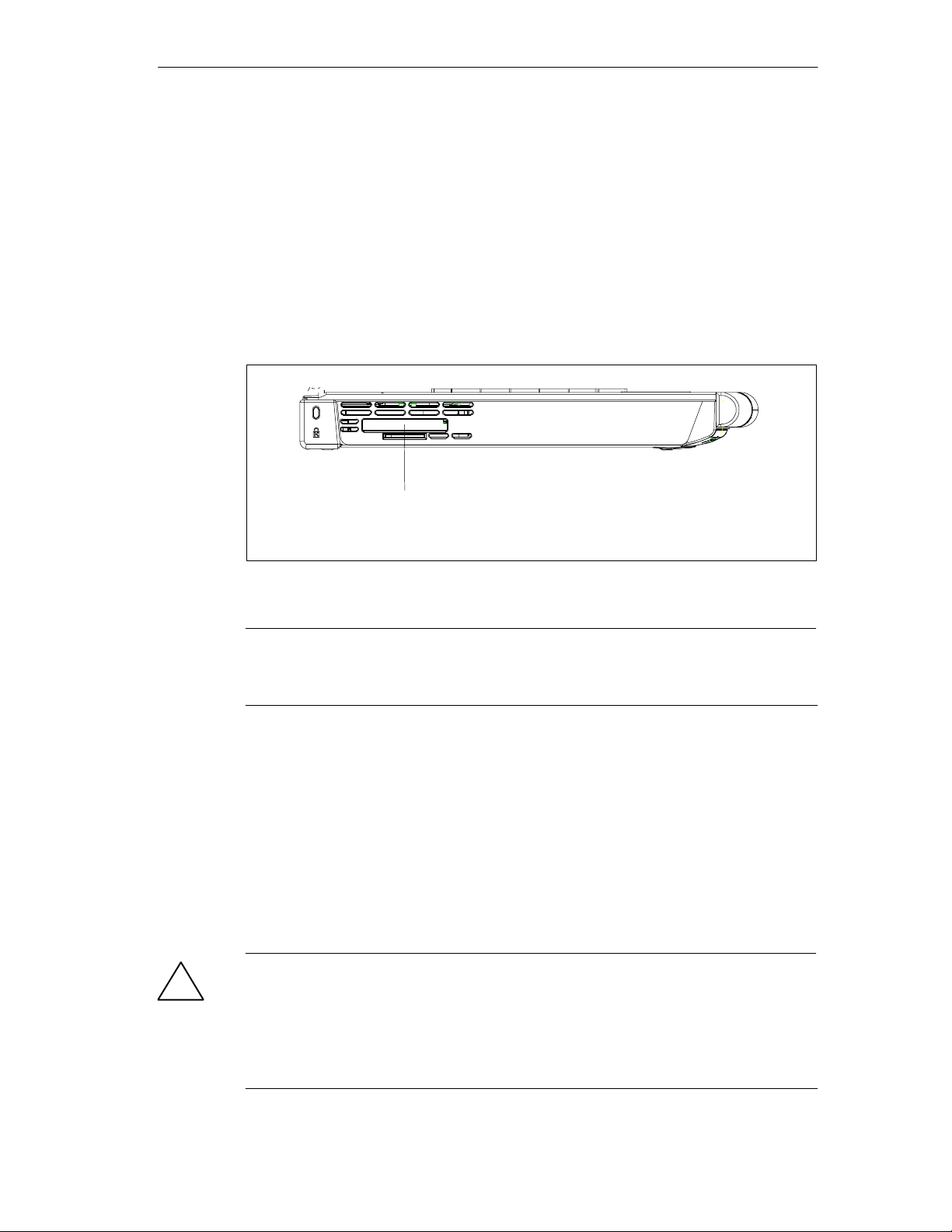
Configuring And Operating The SIMATIC Field PG
3.7 Working with SIMATIC S5 Memory Submodules
Editing SIMATIC S5 Memory Submodules
You can read and program SIMATIC S5 memory submodules (EPROMs or
EEPROMs) via the Memory Card interface. Use the S5 adapter for S5 memory
submodules that is included in the scope of delivery for devices with Step 5
software. The S5 adapter consists of a Memory Card plug with an interface for the
connection of S5 memory modules. Refer to the STEP 5 manual for information on
operating the programming software.
Slot for S5 Adapters,
for SIMATIC S5 memory modules
and SIMATIC Memory Cards
Fig. 3-7 S5 Module Programming Interface
Notice
The S5 adapter and STEP 5 software is not included in all delivered versions.
Proceed as follows when working with S5 memory modules :
1. Switch on your device.
2. In your STEP 5 software, start the function Administration > Edit EPROM.
3. With the type label on the top, insert the SIMATIC S5 Memory Card or the S5
adapter into the Memory Card interface and then the S5 memory module.
4. You can read, program or erase (EEPROMs only) your S5 memory module with
the EPROM functions of the STEP 5 software.
5. Extract the S5 memory module.
6. Close the EPROM functions of your STEP 5 software.
Caution
!
You might damage the module if you insert or extract it while editing is in progress.
You must not remove the S5 memory module as long as the module programming
status display is lit.
Always discharge your body’s static electricity by briefly touching a grounded part
of the device before you insert an S5 Memory Card.
SIMATIC Field PG Manual
A5E00075760-04
3-15
Page 56
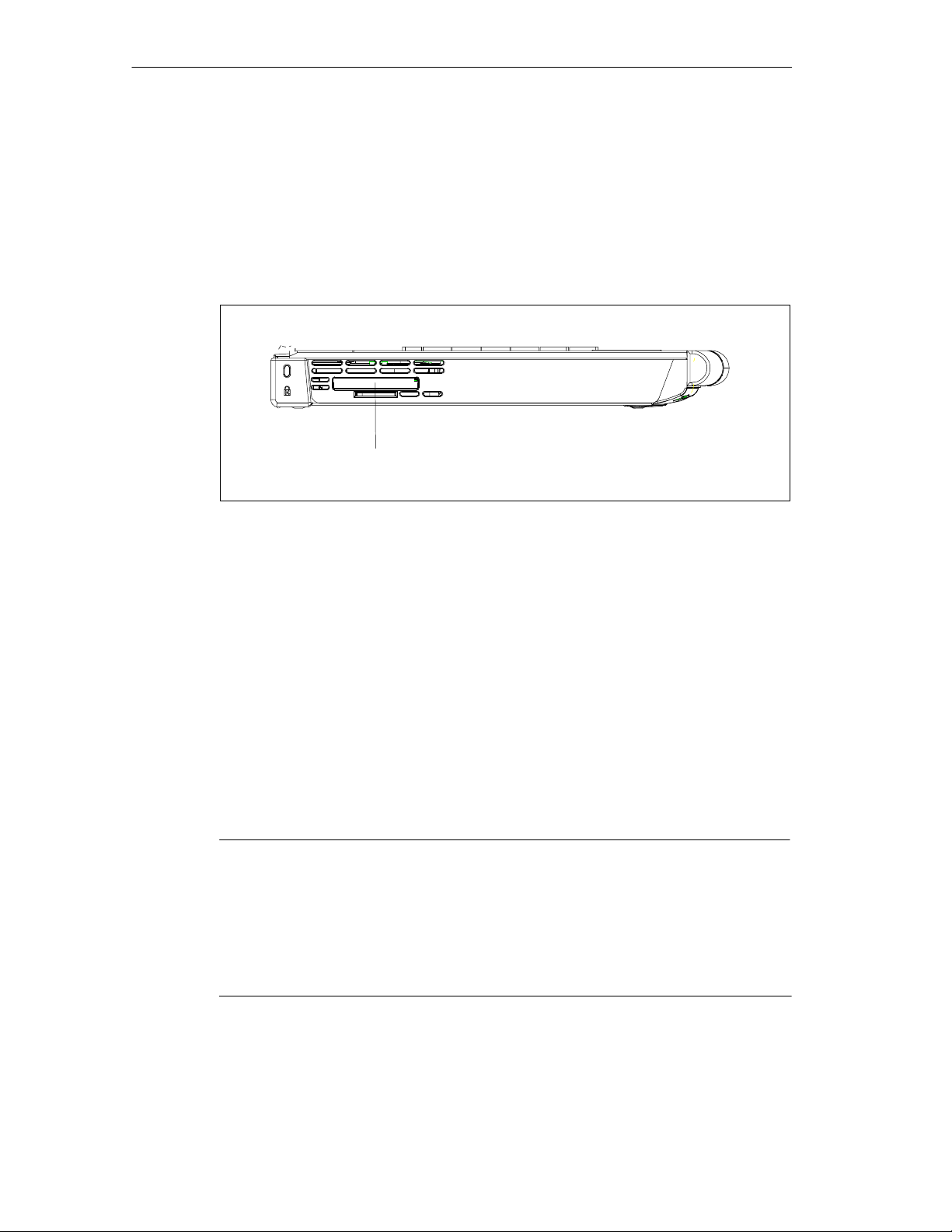
Configuring And Operating The SIMATIC Field PG
3.8 Working with SIMATIC Memory Cards
Working with SIMATIC Memory Cards
SIMATIC memory cards can be read, programmed, and erased. SIMATIC memory
cards are available for SIMATIC S5 and SIMATIC S7 software.
SIMATIC Memory Card
Fig. 3-8 Slot for SIMATIC Memory Cards
Proceed as follows when working with SIMATIC memory cards:
1. Switch on your device.
2. Start your SIMATIC programming function.
3. Plug a SIMATIC Memory Card into the Field PG slot. Correct insertion direction
is spot marked on the Field PG and on the Memory Card.
4. You can read, program, or erase the Memory Card with the programming
function of your SIMATIC programming software.
5. Close the programming function of your SIMATIC software.
6. Remove the SIMATIC memory card from the programming port for further use
in a programmable logic controller.
Caution
You must insert the Memory Card with the type label pointing towards the rear of
the unit.
You must not remove the SIMATIC Memory Card while the module programming
status LED is lit.
Always discharge your body’s static electricity by briefly touching a grounded part
of the device before you insert a SIMATIC Memory Card.
3-16
SIMATIC Field PG Manual
A5E00075760-04
Page 57
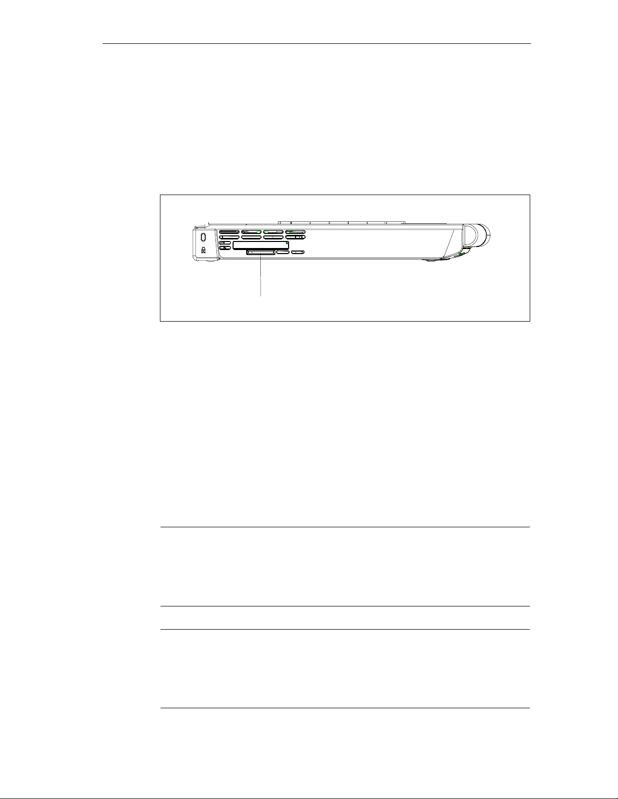
Configuring And Operating The SIMATIC Field PG
3.9 Working with Micro Memory Cards
Working with Micro Memory Cards
Read, program and erase Micro Memory-Cards (MMC) via the Micro Memory Card
interface. Operation with Micro Memory Cards is supported by STEP 7 V5.1 or
higher.
Micro Memory Card
Fig. 3-9 Slot for Micro Memory-Cards
Proceed as follows when working with Micro Memory Cards:
1. Switch on your device.
2. Start your SIMATIC programming function.
3. Insert the Micro Memory-Card into the slot on the side of the device. The card’s
connector is encoded for insertion in one position only (with inclination to the
rear). A symbol on the PG housing indicates the plug-in direction.
4. Read, program, or erase the Micro Memory Card with the programming function
of your SIMATIC programming software.
5. Close the programming function of your SIMATIC programming software.
6. Remove the Micro Memory-Card from the interface.
Caution
You must not remove the SIMATIC Micro Memory Card while the module programming status display is lit.
Always discharge your body’s static electricity by briefly touching a grounded part
of the device before you insert a SIMATIC Micro Memory Card.
Note
Parallel operation of a Micro Memory Card (MMC) and of a Memory Card is not possible. The PG is equipped with a priority circuit that switches off the MMC interface
when a Memory Card is inserted. The internal MMC is switched off a s soon as a Memory Card, an S5 adapter or an MMC adapter is added.
SIMATIC Field PG Manual
A5E00075760-04
3-17
Page 58
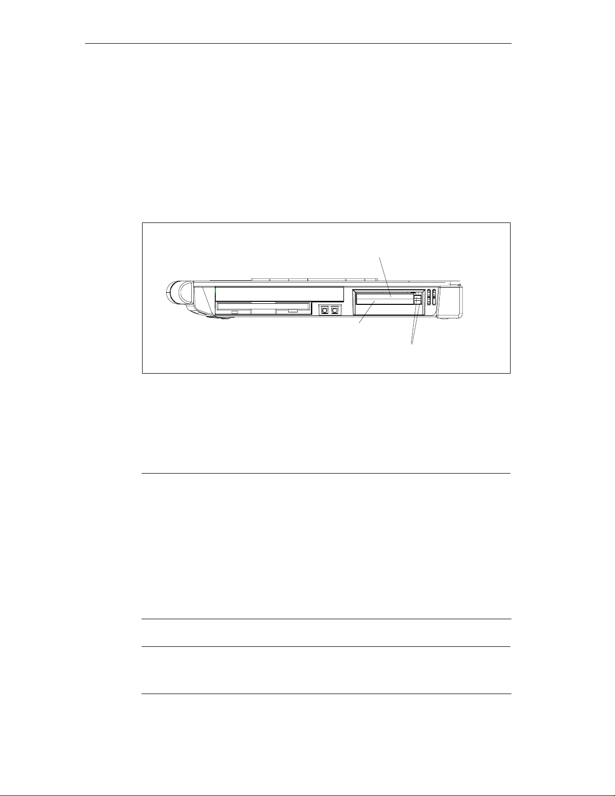
Configuring And Operating The SIMATIC Field PG
3.10 Working with PC Cards
PC-Cards
The PC card interface supports two type II or one type III Cardbus card (32-bit) or
PCMCIA card (16-bit). The SIMATIC Field PG has two PC card ports. You can
plug credit-card format communication modules for MODEM, FAX-MODEM, ISDN,
Token Ring, ETHERNET, memory expansion and SCSI interface modules into
these ports.
PC card interface, type I/II
(Slot 1)
PC card interface, type I/II/III
(Slot 2)
Fig. 3-10 PC Card interface
Ejector for
PC-Cards
The PC-Card ejectors have a ballpoint pen mechanism. Before you insert the card
ensure that the ejector is engaged. To remove the PC-Card, push the ejector once
to unlock it and a second time to eject the card.
Caution
When you plug in the PC-Card, the Label must be on top.
Remove the card only after all data traffic has terminated (risk of data loss and
system failure).
You might damage the SIMATIC Field PG and the PC-Card if you attempt to insert
the card the wrong way round.
Always discharge your body’s charge of static electricity by briefly touching a
grounded part of the device (e.g. the metal mount of the port) before inserting or
removing a card (in accordance with the instructions for handling electrostaticallysensitive components, EGB guidelines). Otherwise, disruptions might occur.
3-18
Notice
In order to use a PC card you must enter BIOS-SETUP, open the Main menu, select the Hardware Option submenu and set “Cardbus/PCMCIA Slot” to “Enabled”.
SIMATIC Field PG Manual
A5E00075760-04
Page 59
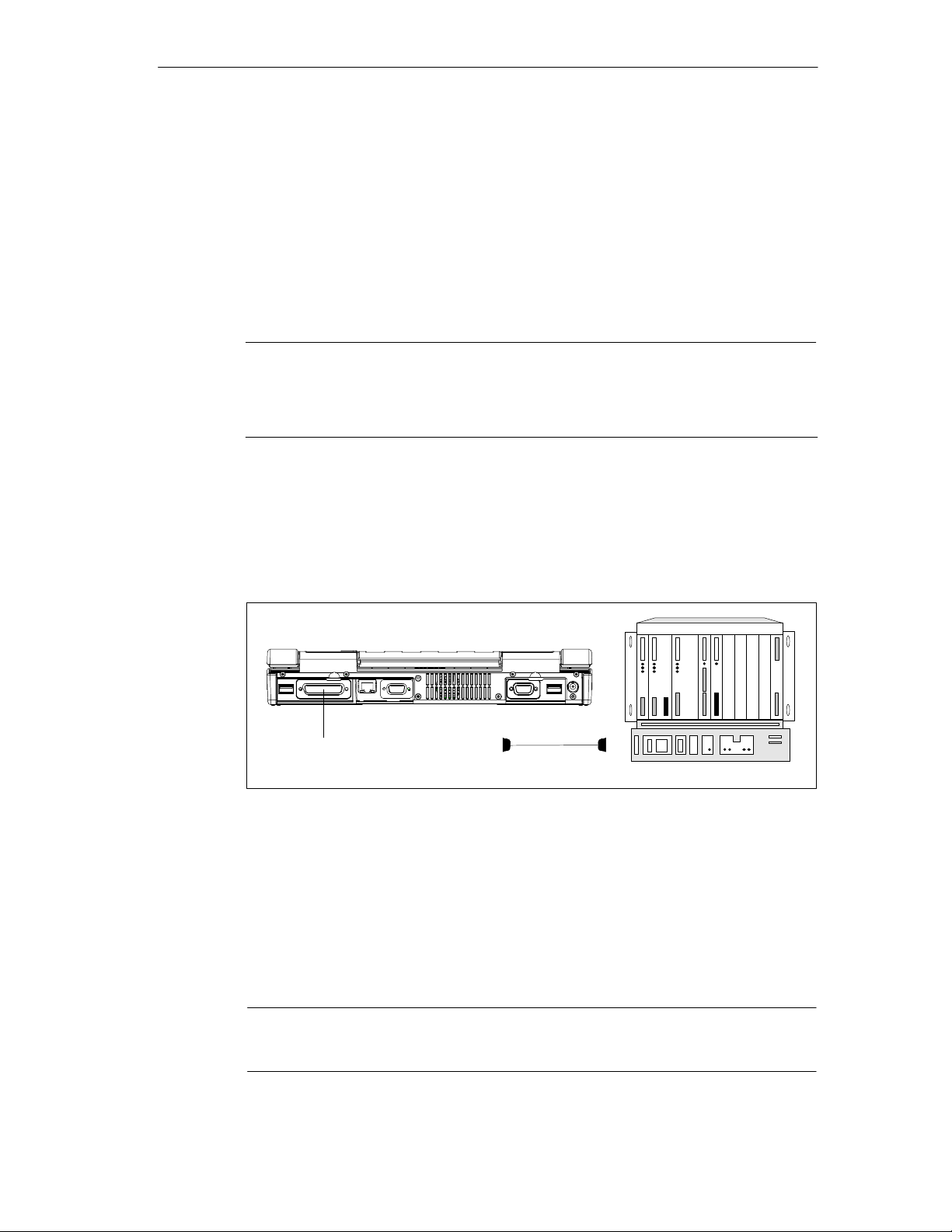
Configuring And Operating The SIMATIC Field PG
3.11 Connecting the Field PG to a SIMATIC S5 Network
Point-To-Point Connection
In this section, you will learn how to connect your Field PG to a programming
device or S5 PLC using a point-to-point connection.
You can establish a point-to-point connection by connecting the Field PG to
another programming device using a TTY connection.
Notice
The interface is connected to potential.
The SIMATIC STEP 5 programming software and the patch cord for the connec-
tion to the S5 PLC is not supplied with all versions.
Connecting the Field PG to the S5 PLC
You can connect the Field PG to a SIMATIC S5 PLC via COM1/TTY interface port.
The patch cord for connecting to SIMATIC S5 CPUs is not included with all
delivered versions (Order no.:6ES5734-2BD20).
COM 1
(Port)
Fig. 3-11 Connecting to an S5 PLC
You connect your Field PG to a SIMATIC S5 PLC as follows:
1. Switch off your device.
2. Open the cover of the interface ports on the rear of the device.
3. Connect the patch cord to the COM1/V.24-Modem/PLC port.
4. Secure the connector with screws.
5. Connect the patch cord to the corresponding port on the CPU of the PLC.
SIMATIC S5 patch cord
Caution
The interface port may be damaged if you use the wrong patch cord.
SIMATIC Field PG Manual
A5E00075760-04
3-19
Page 60
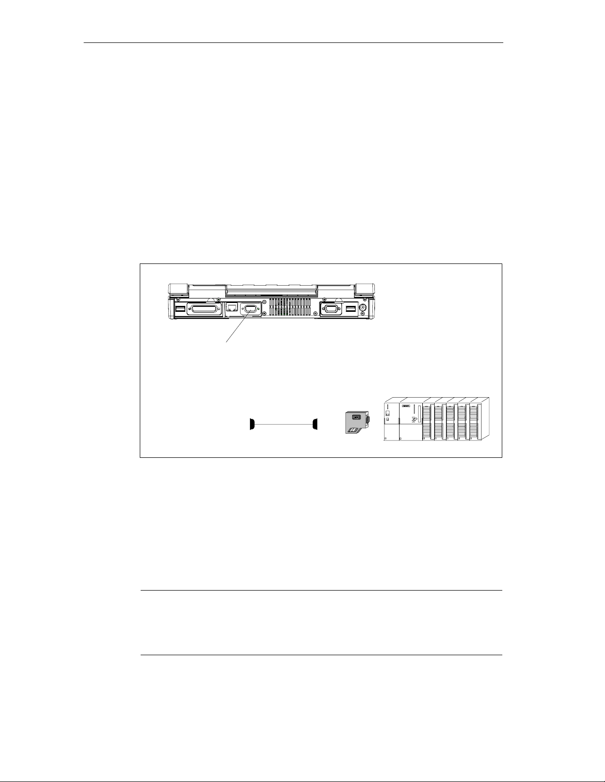
Configuring And Operating The SIMATIC Field PG
3.12 Connecting the Field PG to a SIMATIC S7 Network (MPI/DP)
Connecting an S7 Programmable Controller via an MPI/DP Interface
You can use the potential-separated*) MPI/DP interface to connect the SIMATIC
Field PG to a SIMATIC S7 programmable controller or to a PROFIBUS network.
The MPI patch cord (5m) for connecting to SIMATIC S7-CPUs (Order no.:
6ES7901-0BF00-0AA0) is included in the consignment. The data transfer rate is
limited to 187.5 Kbit/s when using this patch cord. For baud rates > 1.5 Mbit/s you
must use a PROFIBUS cable for 12 Mbit/s (Order no. 6ES7901-4BD00-0XA0).
MPI/DP interface
Fig. 3-12 Connection Using the MPI/DP Interface
For environments free
of interference:
Bus connector
6ES7972-0BB10-0XA0
or
6ES7972-0BB20-0XA0
6ES7901-0BF00-0AA0
(5–m length)
Proceed as follows when connecting to a SIMATIC S7 programmable logic
controller:
1. Switch off your device.
2. Open the interface cover on the left-hand side panel of the device.
3. Connect the cable to the MPI/DP interface.
Caution
Before plugging in the cables, the static charge on your body, the unit, and the
cables must be equalized. You can do this by briefly touching the metal mounting
plate for the interfaces on the rear panel.
3-20
*) Electrical isolation in the safet y extra-low voltage circuit (SELV circuit).
SIMATIC Field PG Manual
A5E00075760-04
Page 61

Connecting
Via the MPI/DP interface, you can connect your programming devices to
• MPI networks (S7-200, S7-300, and S7-400) or
• PROFIBUS DP networks (DP components).
MPI/PROFIBUS DP Network
Up to 32 devices (PC, PG, or AS) can be connected to the MPI/DP interface to
form a network segment. The physical connection to the MPI/PROFIBUS DP
network is via a floating RS485 interface which is a component of the PG basic
module.
Several MPI/PROFIBUS DP network segments can be connected via repeaters.
The complete MPI/PROFIBUS DP network can comprise up to 127 stations. Data
transmission rates from 9.6 Kbps to 12 Mbps are possible in the PROFIBUS-DP
MPI network.
Configuring And Operating The SIMATIC Field PG
SIMATIC Field PG Manual
A5E00075760-04
3-21
Page 62

Configuring And Operating The SIMATIC Field PG
3.13 Networking the Field PG with Other Stations on PROFIBUS
Networking the SIMATIC Field PG on PROFIBUS
PROFIBUS is an open and robust bus system for industrial use. It can be used to
configure networks with up to 32 stations per segment. PROFI BUS -DP suppor ts
data-transfer rates from 9.6 Kbaud to 12 Mbaud.
How the Network Functions
The network operates on the “Master-Slave Principle with Token Passing”
(complying with DIN19245, PROFIBUS). It distinguishes between active and
passive stations. An active station receives the token and passes it on to the next
station within a specified time.
Hardware Requirements
Using the following components, for example, you can connect or network the
SIMATIC Field PG with PROFIBUS:
• RS 485 MPI/DP interface adapter, integrated
• Shielded, twisted pair (bus cable or connecting cable to network).
3.14 Ethernet (RJ45 Ethernet Interface)
Networking Field PG via RJ45 Ethernet Interface
The RJ45 Ethernet interface is a Twisted-Pair (TP) Interface for data transfer rates
of 10/100 Mbaud. This on-board interface is compatible with Intel pro/100+ PCI
Adapters.
The Plug & Play interface is automatically recognized in Windows. Protocols are
configured in the Windows system control.
Notice
A Class 5 Ethernet cable is required for operation with 100 Mbaud.
3-22
SIMATIC Field PG Manual
A5E00075760-04
Page 63

SIMATIC Field PG Expansions
What Does This Chapter Contain?
This chapter shows you how to expand your SIMATIC Field PG with additional
expansion memory submodules to increase its performance. Please note the
included comments on safety.
Chapter Overview
Section Description Page
4.1 Installing Memory Expansion Submodules 4-2
4.2 Processor Upgrade 4-4
4.3 Replacing Backup Battery 4-4
4
SIMATIC Field PG Manual
A5E00075760-04
4-1
Page 64
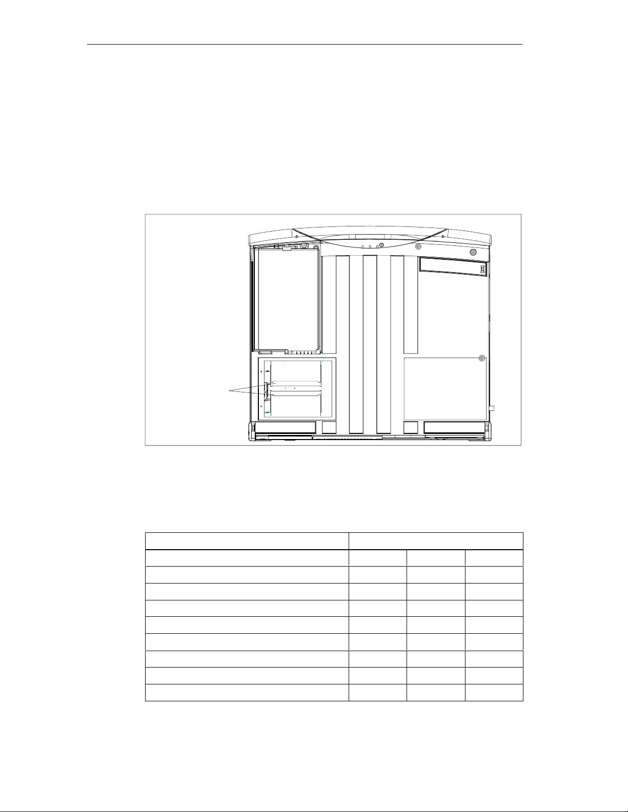
SIMATIC Field PG Expansions
4.1 Installing Memory Expansion Submodules
Standard Memory
The motherboard has 2 slots for 144 pin SO DIMM memory submodules. This
allows you to expand the memory capacity of your SIMATIC Field PG to a
maximum of 512 Mbytes.
Memory Submodules
Fig. 4-1 Positions of the SO DIMM Memory Submodules
You can install submodules of different capacity. Only one module must be
installed. Refer to the catalog for the ordering data for suitable modules.
Memory Modules
64 Mbytes 128 Mbytes 256 Mbytes
64 Mbytes 1 – –
128 Mbytes 2 – –
128 Mbytes – 1 –
192 Mbytes 1 1 –
256 Mbytes – 2 –
256 Mbytes – – 1
384 Mbytes – 1 1
512 Mbytes – – 2
4-2
SIMATIC Field PG Manual
A5E00075760-04
Page 65

Caution
The electronic components of the printed circuit boards are highly sensitive to
electrostatic discharge. Certain precautionary measures are therefore necessary
when handling such components. These measures are explained in the guidelines
for handling electrostatically-sensitive devices in Appendix A.
Installing memory submodules
To plug in expansion submodules, proceed as follows:
1. Switch off the device.
Caution
Do not install a memory module while the PG is switched on. You might damage
the PG as well as the memory module.
SIMATIC Field PG Expansions
2. Disconnect all cables on the device.
3. Close the display unit.
4. Place the Field PG onto a soft mat with the display unit facing down.
5. Remove the four retaining screws of the cover above the memory expansion
slot.
6. Remove the cover.
7. Plug the module into the slot. Note the recess (reversal protection) on the plug
side of the SO DIMM module.
8. Push the module down by applying light pressure until it locks into place.
9. Replace the cover and secure it with the four screws.
Caution
Make sure that the modules are seated securely in the slots, otherwise they can
drop out and be damaged.
The memory configuration is detected automatically. When you switch on the unit,
the distribution of “System and Extended Memory” is displayed on-screen.
SIMATIC Field PG Manual
A5E00075760-04
4-3
Page 66

SIMATIC Field PG Expansions
4.2 Processor Upgrade
You can boost the performance of your SIMATIC Field PG with a processor
upgrade. Consult your local dealer or service partner.
Notice
If an upgrade is implemented, for example to a processor with a different frequency, it may be important to also upgrade the BIOS.
You must only install components approved by Siemens.
4.3 Replacing Backup Battery
The Field PG has a backup battery which powers the hardware clock after the
device has been switched off.
Warning
!
Danger of explosion when replacing the battery improperly. Only replace with the
same type.
The backup battery can be ordered from Siemens as a spare part (order number:
A5E00047601).
Old lithium batteries should be given back to the manufacturer, recycled or disposed of as hazardous waste.
If you have any questions, please consult your local dealer or service partner.
4-4
SIMATIC Field PG Manual
A5E00075760-04
Page 67

Configuring the SIMATIC Field PG
What Does This Chapter Contain?
In this chapter, you will learn how to configure your programming device. You need
to do this if you change your system by adding, removing, or exchanging
expansion modules and memory expansions, or by replacing a system module.
Chapter Overview
Section Description Page
5.1 Changing the Device Configuration with SETUP 5-2
5.2 The Main Menu 5-5
5.3 The Advanced Menu 5-14
5.4 The Security Menu 5-16
5.5 The Power Menu 5-17
5.6 The Boot Menu 5-19
5.7 The Version Menu 5-21
5.8 The Exit Menu 5-22
5
SIMATIC Field PG Manual
A5E00075760-04
5-1
Page 68

Configuring the SIMATIC Field PG
5.1 Changing the Device Configuration with SETUP
Changing the Device Configuration
Your PG configuration is set for working with the software supplied with the unit.
You should only change the preset values if you have modified your Field PG in
any way or if a fault occurs when the unit is powered up.
SETUP-Program
The SETUP program is in the ROM-BIOS. Information about the system
configuration is stored in the battery-buffered RAM of the SIMATIC Field PG.
You can use SETUP to set the hardware configuration (for example, hard disk
type) and define the system characteristics. You can also use SETUP to set the
time of day and date.
Incorrect SETUP Data
If incorrect SETUP data are detected when you boot the system, the BIOS
prompts you to:
• Start SETUP by pressing F2 or
• Continue booting by pressing F1.
Starting SETUP
On completion of the startup test, the BIOS gives you the opportunity of starting
the SETUP program by displaying the following screen prompt:
PRESS < F2 > to enter SETUP
To start SETUP, proceed as follows:
1. Reset your PG (warm or cold restart).
2. Press the F2 key as long as the BIOS prompt appears on the screen.
SETUP Menus
The various menus and submenus are listed on the following pages. You can get
all the information you need for the SETUP entry selected from the “Item Specific
Help” part of the relevant menu.
5-2
SIMATIC Field PG Manual
A5E00075760-04
Page 69

Screen Display Following Power On
With the standard setting of your PG, the screen displays after power-on, for
example:
PhoenixBIOS 4.0 Release 6.0 -A5E0001xxxx-ES00x
Copyright 1985-2000 Phoenix Technologies Ltd.
All Rights Reserved
SIEMENS Field PG
CPU = Intel(R) Mobile Pentium(R)III processor 700MHz
640K System RAM Passed
61M Extended RAM Passed
256K Cache SRAM Passed
System BIOS shadowed
Video BIOS shadowed
UMB upper limit segment address: xxxx
Mouse initialized
Fixed Disk 0: FUJITSU MHK2060AT
ATAPI Removable Drive: LS-120 S200 02 UHD Floppy
ATAPI CD-ROM: TOSHIBA CD-ROM XM-1902B
Configuring the SIMATIC Field PG
Press <F2> to enter SETUP
Notice
All information on on-screen displays and menu displays are samples. Deviations
to this example are possible.
Press the F2 key while the above display is shown, to select the ROM-based BIOS
setup program. In this program, you can set a number of system functions and
hardware configurations of your programming device.
The standard settings are effective on delivery. You can change these settings
using the BIOS setup. The modified settings become effective when you have
saved them and terminated the BIOS setup.
SIMATIC Field PG Manual
A5E00075760-04
5-3
Page 70
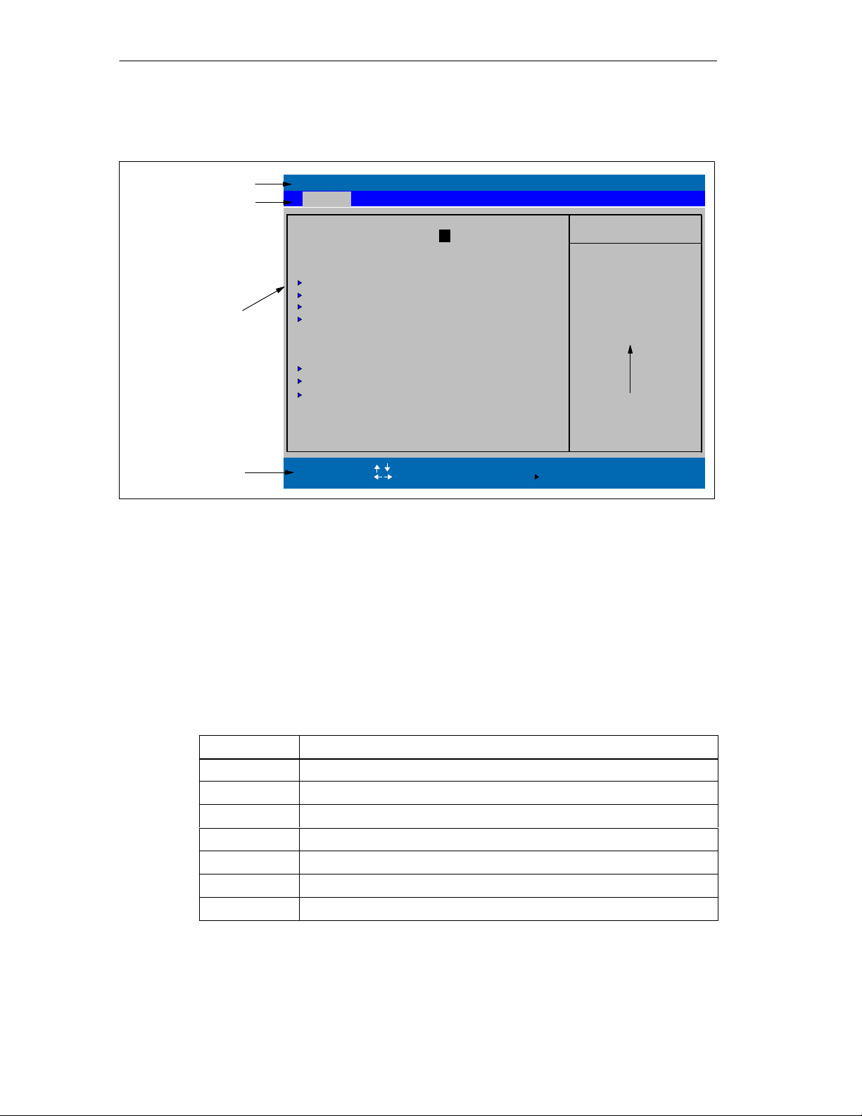
Configuring the SIMATIC Field PG
The following screen form appears when you start the BIOS setup:
Header
Menu bar
System Time:
System Date:
Diskette A: [Disabled]
Primary Master [10056MB]
Primary Slave [None]
Secondary Master [ATAPI Removable]
Secondary Slave [CD-ROM]
Selectable
submenu
Operating keys
Memory Cache:
Boot Options
Keyboard Features
Hardware Options
System Memory:
Extended Memory:
Help
F1
ESC Exit
Fig. 5-1 Main SETUP Menu (sample)
Menu Structure
Advanced Security Power Boot Version ExitMain
PhoenixBIOS Setup Utility
[ 15:35:32 ]
[ 09/05/2000 ]
[Write Back]
640 KB
12851 1 K B
Select Item
Select Menu
+ / -
Enter
Change Values
Select
Sub-MenuF9F10
Item Specific Help
<Tab>, <Shift-Tab>, or
<Enter> selects field.
Example:
Hour/Minute/Second/
Month/Day/Year
Help Window
Setup Defaults
Save and Exit
The screen is divided into four sections. In the top section, you can select the
menu screens [Main], [Advanced], [Security], [Po w er ] , [ B o o t S equence] ,
[Ve rsio n], [Exit]. In the left of the center section you can select various settings or
submenus. Brief help texts appear on the right for the currently selected menu
entry. The bottom section contains information for operator inputs.
You can move between the menu screens using the cursor keys [←] and [→].
Menu Meaning
Main System functions are set here
Advanced An extended system configuration can be set here
Security Security functions are set here, for example a password
Power Power functions can be selected here
Boot The boot priorities are defined here
Version Information about the programming device’s release status
Exit Used for terminating and saving
5-4
SIMATIC Field PG Manual
A5E00075760-04
Page 71
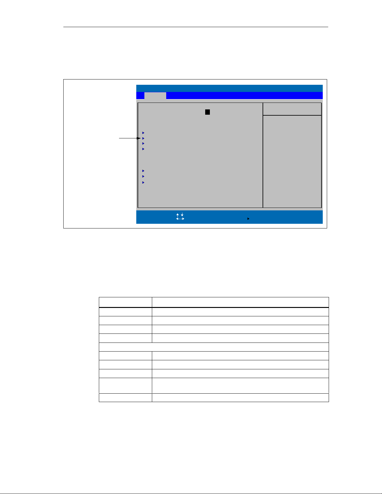
5.2 The Main Menu
Configuring the SIMATIC Field PG
PhoenixBIOS Setup Utility
Advanced Security Power Boot Version ExitMain
Selectable
submenu
Fig. 5-2 Main SETUP Menu
Settings in the Main Menu
In the Main menu, you can move upwards and downwards using the cursor keys
[↑] and [↓] to select the following system parameters:
System Time:
System Date:
Diskette A: [Disabled]
Primary Master [10056MB]
Primary Slave [None]
Secondary Master [ATAPI Removable]
Secondary Slave [CD-ROM]
Memory Cache:
Boot Options
Keyboard Features
Hardware Options
System Memory:
Extended Memory:
Help
F1
ESC Exit
[ 15:35:32 ]
[ 09/05/2000 ]
[Write Back]
12851 1 K B
Select Item
Select Menu
640 KB
+ / -
Enter
Change Values
Select
Sub-MenuF9F10
Item Specific Help
<Tab>, <Shift-Tab>, or
<Enter> selects field.
Example:
Hour/Minute/Second
Month/Day/Year
Setup Defaults
Save and Exit
System Time For viewing and setting the current time
System Date For viewing and setting the current date
Diskette A Type of built-in floppy disk drive
Memory Cache For setting the cache options
By submenus
Primary Master Type of built-in drives
Secondary Master Type of built-in drives
Boot Options For setting boot options
Keyboard
Features
Hardware Options For setting PG hardware options
SIMATIC Field PG Manual
A5E00075760-04
Field Meaning
For setting keyboard-interface options (e. g. NUM Lock, Typematic
Rate)
5-5
Page 72
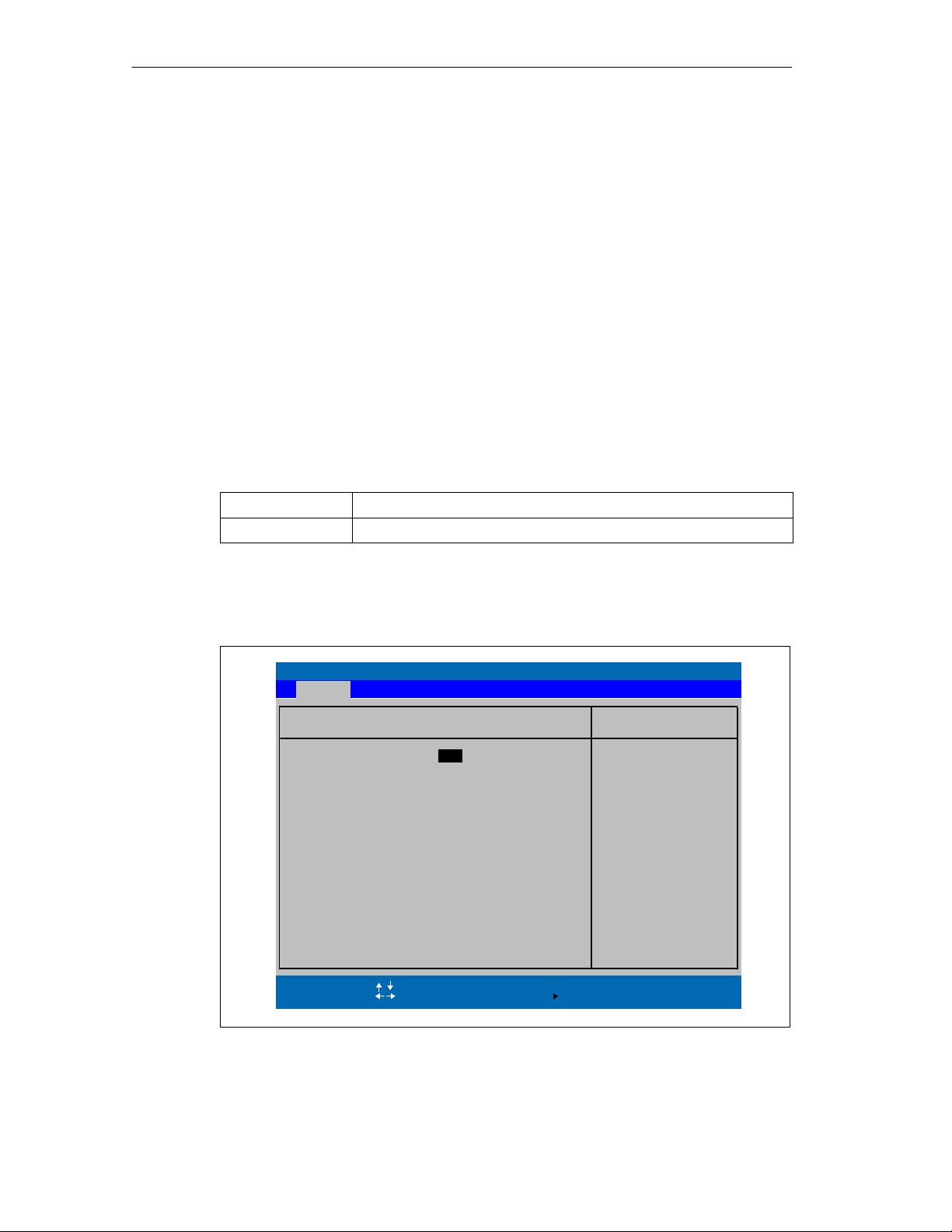
Configuring the SIMATIC Field PG
System Time und System Date
System Time and System Date indicate the current values. Once you have
selected the appropriate option, you can use the [+] and [-] keys to modify the time
setting
Hour:Minute:Second
and the date
Month/Day/Year.
You can move between the entries in the date and time options (for example, from
hour to minute) using the tabulator key.
Diskette A
The type of disk drive built-in to the PG is set here. The following entries are
possible:
[Disabled] If a floppy drive or an LS120 drive does not exist (default)
[1.44 MB, 3 1/2”] Setting for an integrated floppy drive A: for 3 1/2 inch/1.44 MB disks
Primary Master
When you select such a menu field via Enter key the following submenu is opened:
Primary Slave Secondary Master / Secondary Slave
PhoenixBIOS Setup Utility
Main
Primary Master [10056 MB]
Type:
Total Sectors: 19640880
Maximum Capacity: 10056MB
Multi-Sector Transfers: [16 Sectors]
LBA Mode Control: [Enabled]
32 Bit I/O: [Enabled]
Transfer Mode:
[ Auto ]
LBA Format
User = you enter
parameters of hard-disk
drive installed at this
connection.
Auto = autotypes
hard-disk drive
installed here.
1–39 = you select
pre-determined type of
hard-disk drive
installed here.
CD-ROM = a CD-ROM
drive is installed here.
ATAPI Removable =
removable disk drive is
installed here.
Item Specific Help
5-6
Help
F1
ESC Exit
Fig. 5-3 Primary Master
Select Item
Select Menu
+ / –
Enter
Change Values
Select
Sub-MenuF9F10
Setup Defaults
Save and Exit
SIMATIC Field PG Manual
A5E00075760-04
Page 73

”Type” Field
The parameters you can select here are usually stored on the IDE drive. The ’Auto’
setting in the ’Type’ field means that these values are automatically read from the
drive and written into memory .
If Type is selected for a drive that cannot be detected, a timer times out in
approximately 1 minute and the entries remain unchanged. You should always
check that the interfaces for which you select ’Auto’ are in fact connected to drives.
Select “User” if you want to define the hard-disk type yourself, in which case
remember that you also have to set the other fields, including Cylinder, Heads,
Sectors/Track and WritePrecomp, to the correct values for the type of hard disk in
question.
”Multi-Sector Transfer” Field
The entry in the Multi-Sector Transfer field defines the number of sectors
transferred per interrupt. The value depends on the drive and should be set only by
setting the
Type
field to
Auto
Configuring the SIMATIC Field PG
.
Disabled
2,4,8,16 sectors
”LBA Mode Control” field
If the LBA Mode Control field (enabled, disabled) is set to ’Enabled’, the system
supports hard disks with capacities greater than 528 Mbytes. The value depends
on the drive and should be set only by setting the
”32 Bit I/O” Field
The setting in the 32 Bit I/O field defines the mode of access for the drive
Disabled 16-Bit access
Enabled 32-Bit access (default)
”Transfer Mode” Field
The settings in these fields define the interface’s data-transfer rate. The value
depends on the drive and should be set only by setting the
Hit ESC to exit the submenu.
Type
field to
Type
Auto
.
field to
Auto
.
SIMATIC Field PG Manual
A5E00075760-04
5-7
Page 74
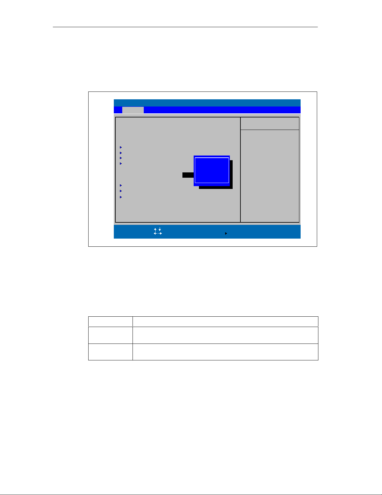
Configuring the SIMATIC Field PG
“Memory Cache” Field
The following pop-up menu appears when you select the option “Memory cache” in
the main menu:
PhoenixBIOS Setup Utility
Advanced Security Power Boot Version ExitMain
System Time:
System Date:
Diskette A: [ Disabled ]
Primary Master [10056MB]
Primary Slave [None]
Secondary Master [ATAPI Removable]
Secondary Slave [CD-ROM]
Memory Cache:
Boot Options
Keyboard Features
Hardware Options
System Memory:
Extended Memory:
Help
F1
ESC Exit
[ 15:35:32 ]
[ 09/05/2000 ]
[Write Back]
12851 1 K B
Select Item
Select Menu
Disabled
Write Through
Write Back
640 KB
+ / –
Enter
Change Values
Select
Item Specific Help
Controls caching of
system conventional
memory and memory
above one megabyte.
Sub-MenuF9F10
Setup Defaults
Save and Exit
Fig. 5-4 “Memory Cache” Menu
A cache is a fast memory buffer between the CPU and main memory (DRAM).
Recurrent memory access operations are executed in the fast cache, instead of
main memory, if the function is enabled. In rare instances involving some hardware
and software combinations, it may be necessary to disable the cache because the
program runtimes or waits are too short on account of the fast cache.
5-8
[Disabled] Cache is disabled
[Write Through] Write access is not concluded until the entry has been made in main
memory
[Write Back] Write access is concluded immediately, the entry in main memory takes
place in the background (default)
SIMATIC Field PG Manual
A5E00075760-04
Page 75
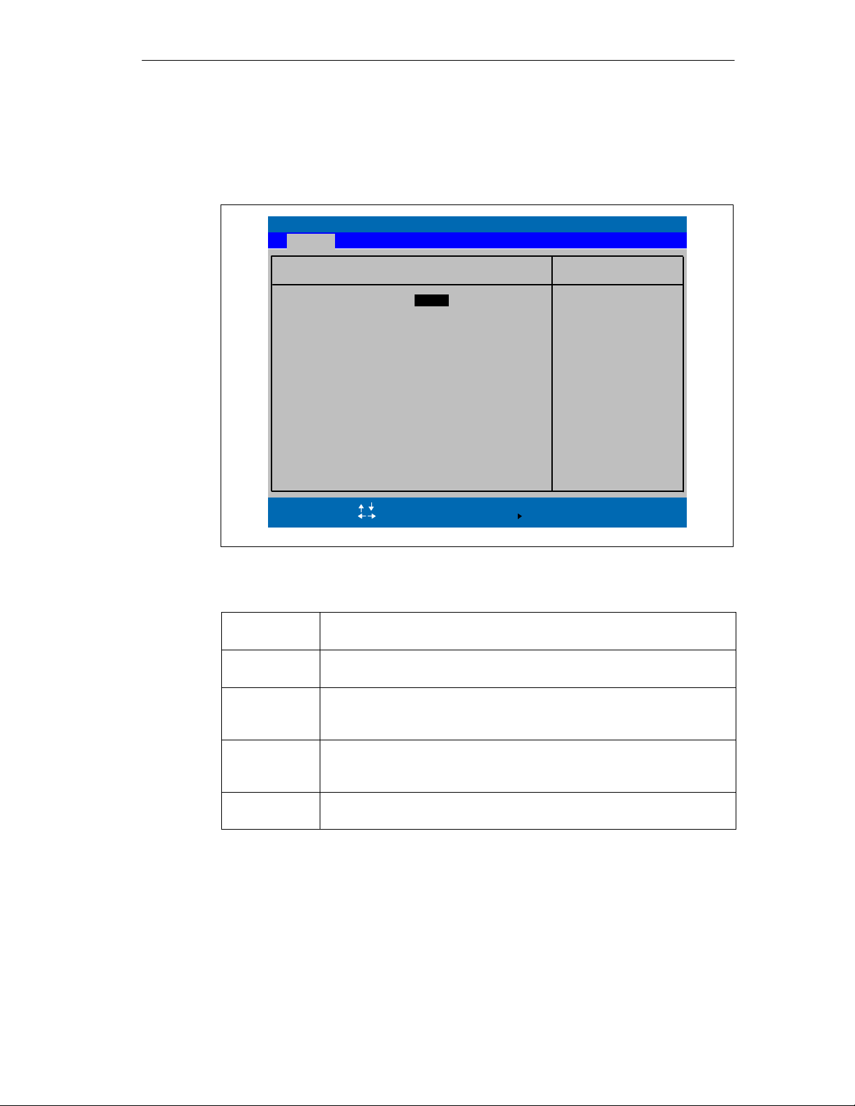
Option “Boot Options”
The following submenu appears when you select the option “Boot Options” in the
main menu:
Main
Configuring the SIMATIC Field PG
PhoenixBIOS Setup Utility
Boot Options
QuickBoot Mode:
SETUP prompt: [Enabled]
POST Errors: [Enabled]
Floppy check:
Summary screen:
Help
F1
ESC Exit
[Enabled]
[Disabled]
[Disabled]
Select Item
Select Menu
+ / –
Enter
Change Values
Select
Item Specific Help
Allows the system to
skip certain tests
while booting. This
will decrease the
time needed to boot
the system.
Sub-MenuF9F10
Setup Defaults
Save and Exit
Fig. 5-5 ”Boot Options” Submenu
Quick Boot
Some hardware tests are skipped to speed up the boot procedure.
Mode
SETUP prompt The message
PRESS <F2> to enter Setup
appears at the bottom of the
screen during the system run-up phase.
POST Errors The boot process is stopped if an error is detected; you must press F1 to
confirm. Enter “Disabled”to avoid the necessity of acknowledging errors,
for example if no keyboard is connected.
Floppy check The floppy head is stepped inward and then back to its original position
during the system run-up phase. This test is useful because it reinitializes the drive.
Summary
screen
The most important system parameters are displayed when the system
run-up phase completes.
’Enabled’ means that the feature is active. ’Disabled’ means that the feature is
inactive.
SIMATIC Field PG Manual
A5E00075760-04
5-9
Page 76

Configuring the SIMATIC Field PG
Example of a Summary screen:
PhoenixBIOS Setup Utility
SIMATIC PG
CPU Type
CPU Speed
System Memory
Ext.Memory
Shadow Ram
Cache Ram
Hard Disk 0
Hard Disk 1
Hard Disk 2
Hard Disk 3
: Field PG Pentium III
: Pentium(R) III
: 550 MHz
: 640 KB
: 128511 KB
: 65408 KB
: 256 KB
: 10056MB
: None
: ATAPI Removable
: CD-ROM
BIOS Number
System ROM
BIOS Date
COM Ports
LPT Ports
Display Type
PS/2 Mouse
Diskette A
: A5E0001xxxx-ES00x
: E7A6 - FFFF
: 09/05/00
: 03F8
: None
: EGA/VGA
: Installed
: Disabled
Fig. 5-6 Summary Screen
The Summary screen appears when the system run-up phase completes.
5-10
SIMATIC Field PG Manual
A5E00075760-04
Page 77
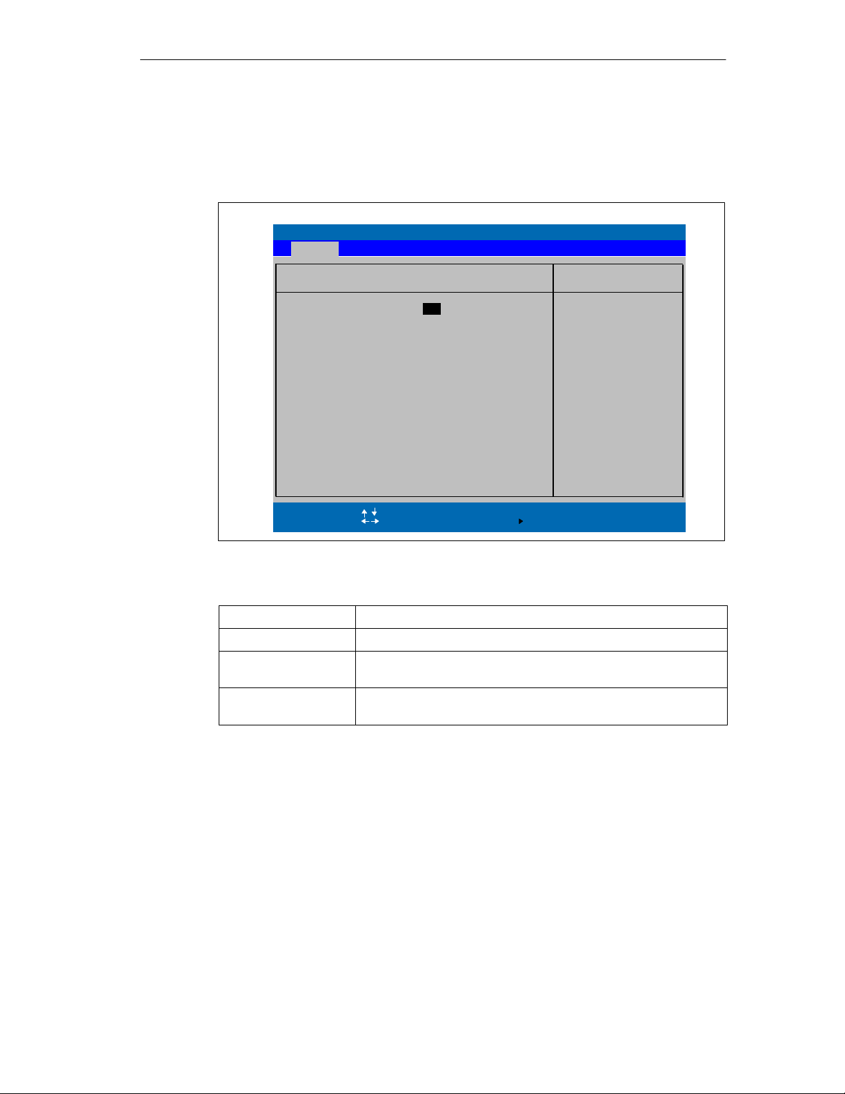
Option “Keyboard Features”
The following submenu appears when you select the “Keyboard Features” field in
the main menu:
Main
Configuring the SIMATIC Field PG
PhoenixBIOS Setup Utility
Keyboard Features
NumLock:
Key Click: [Disabled]
Keyboard auto-repeat rate:
Keyboard auto-repeat delay:
Help
F1
ESC Exit
[ Off ]
[30/sec]
[1/2 sec]
Select Item
Select Menu
+ / –
Enter
Change Values
Select
Item Specific Help
Selects Power-On state
for NumLock on next boot
Sub-MenuF9F10
Fig. 5-7 ”Keyboard Features” Submenu
Numlock Switches Numlock on or off following power on
Key Click A keystroke can be heard
Keyboard auto-repeat
Increase of the automatic keyboard rate
rate
Keyboard auto-repeat
On-delay of automatic keyboard repeat
delay
Setup Defaults
Save and Exit
SIMATIC Field PG Manual
A5E00075760-04
5-11
Page 78
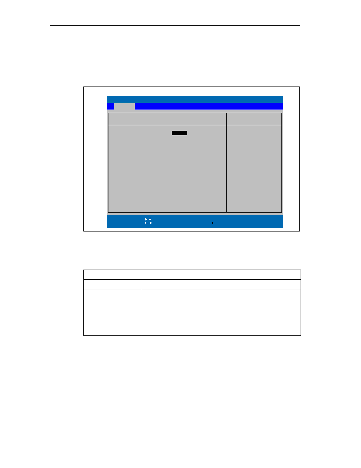
Configuring the SIMATIC Field PG
“Hardware Options” Field
The following submenu appears when you select the “Hardware Options” field in
the main menu:
Main
PhoenixBIOS Setup Utility
Hardware Options
PCI – MPI / DP:
Programming interface: [Enabled]
Cardbus / PCMCIA Slot:
Onboard Ethernet
Ethernet Address
LAN Remote Boot:
CRT / LCD selection: [Simultan Auto]
LCD-Screensize: [Expand]
Touch-Pad
Help
F1
ESC Exit
[ Enabled ]
[Enabled]
[Enabled]
08000624E1CB
[Disabled]
[Auto Detect]
Select Item
Select Menu
+ / –
Enter
Change Values
Select
Item Specific Help
Enable or disable the
PCI - Multi Point
Interface (MPI/DP).
Also, this item
Enables / Disables the
SIMATIC programming
interface.
Sub-MenuF9F10
Setup Defaults
Save and Exit
Fig. 5-8 ”Hardware Options” Submenu
The parameters of the interfaces present on the basic module are set here.
Entry Meaning
PCI - MPI / DP Enables the CP5611 compatible MPI/DP interface.
Programming interface Displays enable or disable status of the SIMATIC Memory Card
Interface. Enable follows the enable of PCI-MPI/DP.
Cardbus / PCMCIA
Slot
[Disabled] Enable Cardbus / PCMCIA-
interface deactivated.
[Enabled] Resources are managed by BIOS PCI
Plug & Play mechanisms.
5-12
SIMATIC Field PG Manual
A5E00075760-04
Page 79

Configuring the SIMATIC Field PG
Entry Meaning
Onboard Ethernet Enable the on-board Ethernet interface. Resources are managed
by the BIOS PCI Plug & Play mechanism.
[Disabled] Ethernet inactive.
Ethernet interface hardware is switched off.
The operating system can not operate the interface
[Enabled] Ethernet active.
Subsequent plugging of the network cable
and its operation possible at any time (Hot-Plug).
If no cable is plugged on system start
the device checks during the boot sequence, for a
time of approx. 30 seconds, and when recovering
from suspend mode, for a time of approx.
40 seconds, for an existing Ethernet connection.
Noticeable delays do not occur as long as an
active network connection does not exist.
LAN Remote Boot [Enabled] [Disabled]
Switch on/off Oprom scan to activate remote
boot via the onboard Ethernet.
CRT / LCD selection [LCD only] All data is output only to the internal
LCD, the 15-way VGA port is disabled
[CRT only] For maximum resolution the display
signals are output only to the 15-way
VGA port; the LCD interface of the VGA
controller is disabled.
[Simultan. Auto] Choose Simultan. Auto if sometimes a CRT is
connected, CRT will only be active if connected.
[Simultan. Forced CRT] Both display interfaces are enabled
and operate simultaneously. Note,
however, that the LCD does not
support all resolutions.
LCD Screensize [Normal] The display window in Text and Graphic
modes is not expanded to full screen size.
[Expand] The Graphic and Text modes are expanded
to full screen size.
Touchpad [Enabled] The Touchpad is switched on.
[Disabled] The Touchpad is switched off
[Auto Detect] The Touchpad is automatically detected.
Note: All modifications of this interface are not active
until a restart of the PG.
Sound Enabling/disabling the soundchips of the basic module.
SIMATIC Field PG Manual
A5E00075760-04
5-13
Page 80
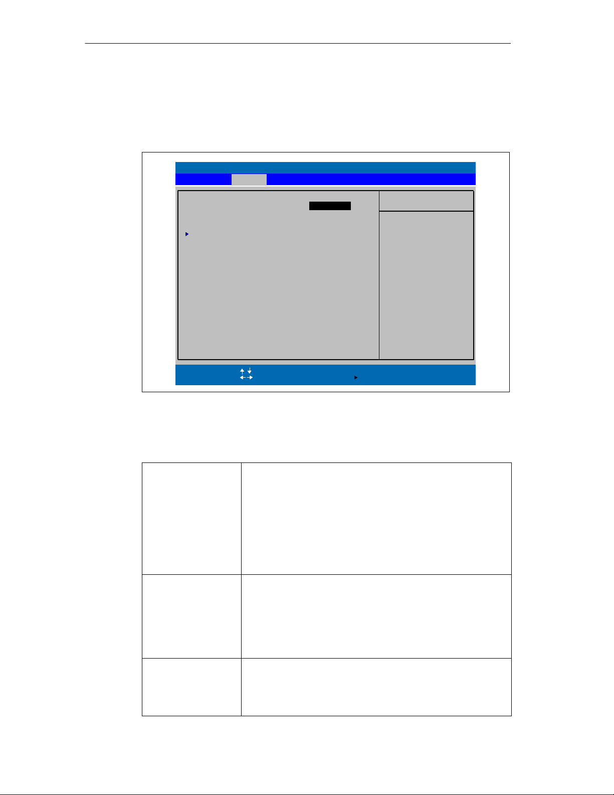
Configuring the SIMATIC Field PG
5.3 The Advanced Menu
Menu Structure
Advanced
PhoenixBIOS Setup Utility
Security Power Boot Version ExitMain
Installed O/S:
Reset Configuration Data:
IRQ Resource Exclusion
Serial port A: [Auto]
Floppy disk controller: [Disabled]
Large Disk Access Mode: [DOS]
Local Bus IDE adapter: [Primary & Secondary]
Legacy USB Support: [Disabled]
Help
F1
ESC Exit
Fig. 5-9 ”Advanced” Menu
Settings in the Advanced Menu
Installed O/S Plug & play means that all modules are automatically detected
Reset Configuration
Data
Serial port A Configure Serial Port A with the options:
Item Specific Help
Select the operating
system installed
on your system which
you will use most
commonly.
Note: An incorrect
setting can cause
some operating
systems to display
unexpected behavior.
Sub-MenuF9F10
Setup Defaults
Save and Exit
Select Item
Select Menu
[ WinMe/2000 ]
[ No ]
+ / –
Change Values
Select
Enter
and installed, providing they support the Plug&Play functionality.
[other] BIOS handles the entire Plug&Play capability, default
configuration
[WinME] The operating system handles part of the Plug& Play
functions
[WinME/2000]
The operating system handles a part of the
Plug&Play functions
[Yes] All installations under Plug&Play are deleted and
reconfiguration is triggered the next time the system
boots. The entry is then reset to [No]. System
components that do not support Plug&Play have to be
entered manually.
[No] The Plug&Play system components are initialized
after the next system start.
[Disabled] No configuaration
[Enabled] User configuration
[Auto] BIOS or OS chooses confuguration.
5-14
SIMATIC Field PG Manual
A5E00075760-04
Page 81
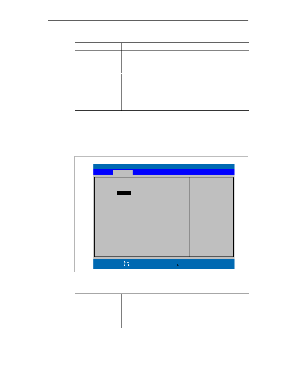
Floppy disk controller Enabling or disabling the floppy controller of the basic module
Large Disk Access
Mode
[OTHER] The tables are not adapted.
[DOS] Drive letters are constructed according to
Local Bus IDE adapter [Disabled] No local IDE adapter.
[Primary] One IDE adapter for max. two drives.
[Secondary]
[Primary & Secondary] Two IDE adapters for max. four drives.
Legacy USB Support [Disabled] Disables the support for Legacy USB
[Enabled] Enables support for Legacy USB
The resources used by an interface are released when you disable the interface in
question.
Submenu IRQ Resource Exclusion
The I/O addresses and interrupts are default settings and recommended
respectively.
Configuring the SIMATIC Field PG
Enhanced IDE compatible
DOS drive access.
PhoenixBIOS Setup Utility
Advanced
IRQ Resource Exclusion
Help
[ Available ]
Select Item
Select Menu
+ / –
Enter
Change Values
Select
IRQ 3:
IRQ 4: [Available]
IRQ 5: [Available]
IRQ 7: [Available]
IRQ 9: [Available]
IRQ 10: [Available]
IRQ 11: [Reserved]
F1
ESC Exit
Fig. 5-10 ”IRQ Resource Exclusion” Submenu
IRQ
Available IRQ can be assigned by the BIOS Plug&Play
mechanism to Plug and Play modules or to basic
board functions.
Reserved Must only be set if the respective interrupt is not to
be specifically assigned to a Plug & Play
PCMCIA module.
Item Specific Help
Reserves the specified
IRQ for use by legacy
ISA devices
Sub-MenuF9F10
Setup Defaults
Save and Exit
SIMATIC Field PG Manual
A5E00075760-04
5-15
Page 82
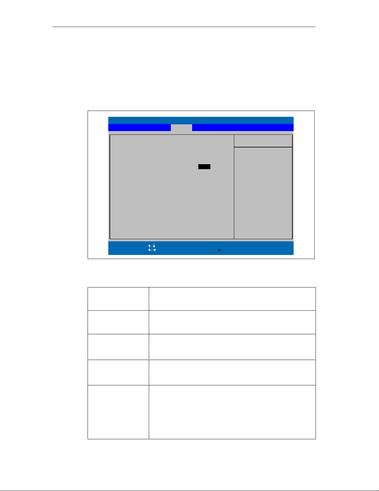
Configuring the SIMATIC Field PG
5.4 The Security Menu
You can only edit the fields enclosed in square brackets. Two passwords are
assigned to protect your programming device from unauthorized use. You can use
the supervisor password to prevent use of diskettes for the normal user and to limit
use of the hard disk.
Advanced Security
PhoenixBIOS Setup Utility
Power Boot Version ExitMain
Supervisor Password is:
User Password is:
Set User Password
Set Supervisor Password
Password on boot: [Disabled]
Fixed disk boot sector: [Normal]
Diskette access: [Supervisor]
Help
F1
ESC Exit
Select Item
Select Menu
+ / –
Enter
Disabled
Disabled
[ Enter ]
[ Enter ]
Change Values
Select
Item Specific Help
Supervisor Password
controls access to the
setup utility
Sub-MenuF9F10
Setup Defaults
Save and Exit
Fig. 5-11 ”Security” Menu
Set Supervisor Password
This field opens the dialog box for entering a password. Once it
has been entered, the supervisor password can be changed or
deleted by pressing ”Return” and thus deactivated.
Set User Password This field opens the dialog box for entering a password. Once it
has been entered correctly, the user password can be changed
or deleted by pressing ”Return” and thus deactivated.
Password on boot [Disabled] No password required for system boot.
[Enabled] Supervisor or user password must be entered for
system boot.
5-16
Fixed disk boot sector Normal All types of hard-disk access are permitted.
protected No operating system can be installed.
This is a way of protecting against boot viruses.
Diskette access This mode of protection is not active unless ”Password on boot ”
is set to [enabled].
Supervisor Diskette access is not possible unless the
supervisor password was entered during
system boot.
User Diskette access is not possible unless the
user password was entered during system boot.
SIMATIC Field PG Manual
A5E00075760-04
Page 83
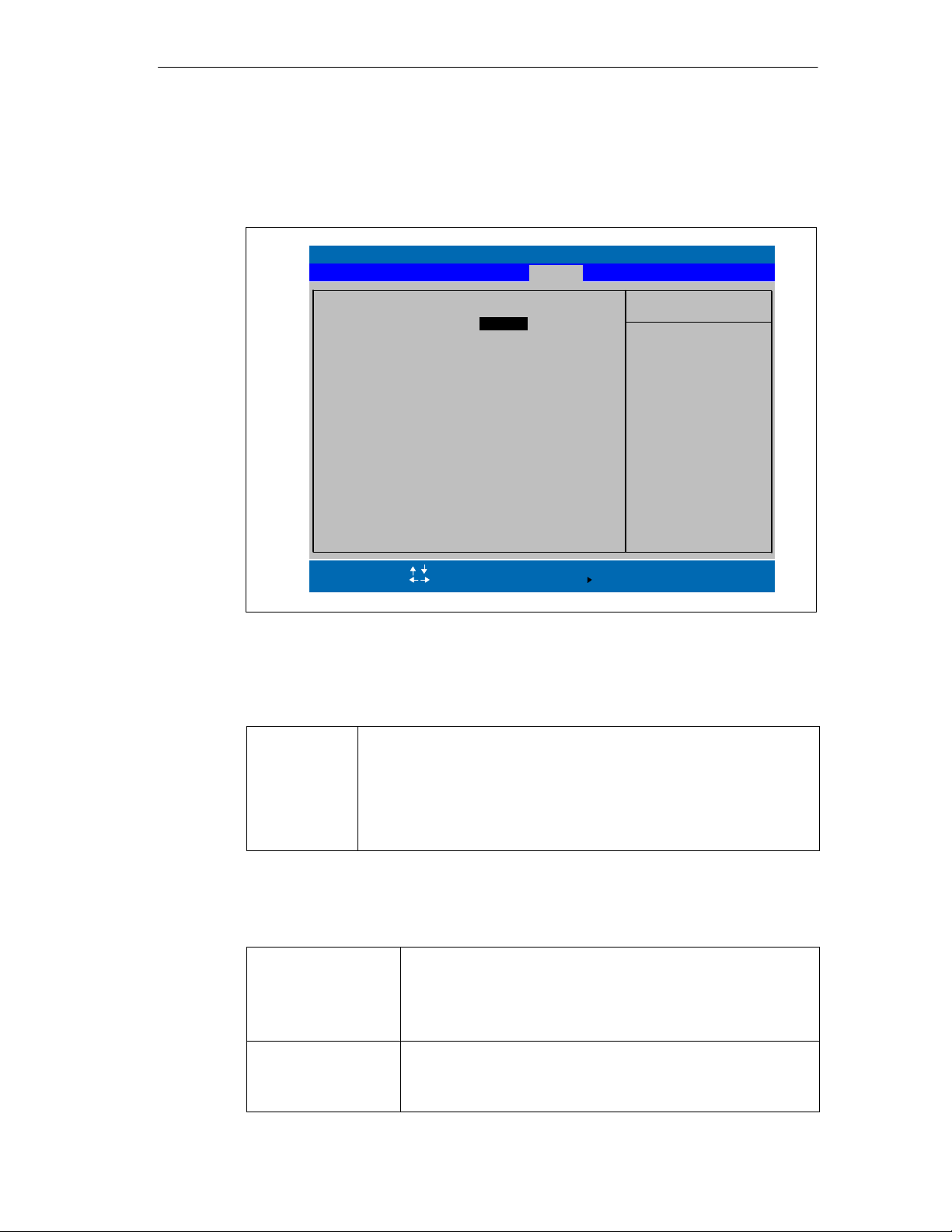
5.5 The Power Menu
This menu has the following structure:
Advanced Security Boot Version ExitMain
Power Savings:
Hard Disk Timeout: [Disabled]
Resume On Time [Off]
Resume Time: [00.00.00]
Resume On Modem Ring: [Off]
After Power Failure: [Stay Off]
Configuring the SIMATIC Field PG
PhoenixBIOS Setup Utility
Power
[Enabled]
Item Specific Help
[Enabled] [Disabled]
Switch on/off Power
Savings to conserves
system power.
To turn off power
management, choose
Disabled, but remember
Power Button also did
not functioning.
Help
F1
ESC Exit
Select Item
Select Menu
+ / –
Enter
Change Values
Select
Sub-MenuF9F10
Setup Defaults
Save and Exit
Fig. 5-12 “Power” Menu
The Power menu offers a number of power-saver modes for environmentally
friendly computing:
Power Savings [Disabled] No power-saving functions
[Customize, Maximum Power Savings, Maximum Performance]
User-selectable and preset power-saving functions
for maximum and minimum power saving.
You can set the parameters for Standby/Suspend
Timeouts and Fixed Disk Timeout or they set
automatically to their defaults.
Major components are shut down in suspend mode. The information needed for
reactivating the programming device is buffered.
Hard Disk Timeout [Disabled] The hard disk does not shut down.
[10, 15, 30, 45] Seconds or
[1, 2, 4, 6, 8, 10, 15] Minutes after the last hard disk access
Resume On Time [On] If this function is enabled the
[Off] ’Off’ means this function is disabled.
The next time it is accessed, the hard disk
starts spinning again after a brief delay.
programming device is automatically
switched on at the preset time.
SIMATIC Field PG Manual
A5E00075760-04
5-17
Page 84

Configuring the SIMATIC Field PG
Resume Time Time for automatic restart
Resume On Modem
Ring
After Power Failure [Stay Off] After power failure the device is not switched
Enabled wakes the system up when an
incoming call is detected on your modem.
on automatically.
[Last State] Provided it was switched on prior to a power
failure, the device is switched on again
[Power On] Restores the previous power state before
loss occured.
5-18
SIMATIC Field PG Manual
A5E00075760-04
Page 85
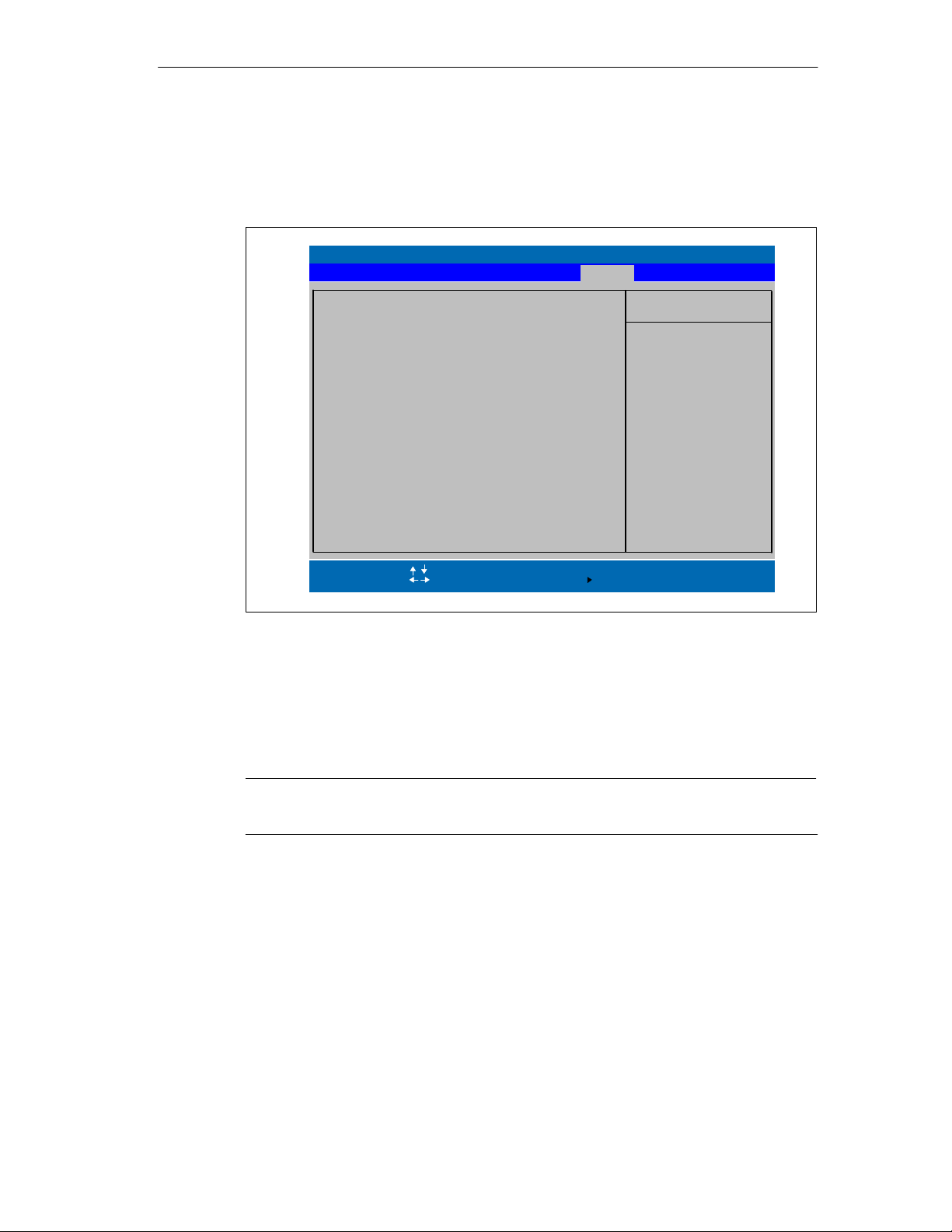
5.6 The Boot Menu
This menu allows you to set the priority of boot devices.
+Removable Devices
+Hard Drive
CD-ROM Drive
Network Boot
PhoenixBIOS Setup Utility
Advanced Security Version ExitMain Power
Configuring the SIMATIC Field PG
Boot
Item Specific Help
Keys used to view or
configure devices:
<Enter> expands or
collapses devices with
a + or <Ctrl+Enter> expands
all
<+> and <-> moves
the device up or down.
Help
F1
ESC Exit
Select Item
Select Menu
+ / -
Enter
Change Values
Select
Sub-MenuF9F10
Setup Defaults
Save and Exit
Fig. 5-13 The ”Boot” Menu
This menu lists the boot devices in groups. The group with the highest priority is at
the top. The procedure for changing the sequence is as follows:
Use the ↑↓ keys to select a group and the + or - keys to move the group to its
new position in the sequence.
Note
During booting the boot drive can be selected with the ESC key.
SIMATIC Field PG Manual
A5E00075760-04
5-19
Page 86
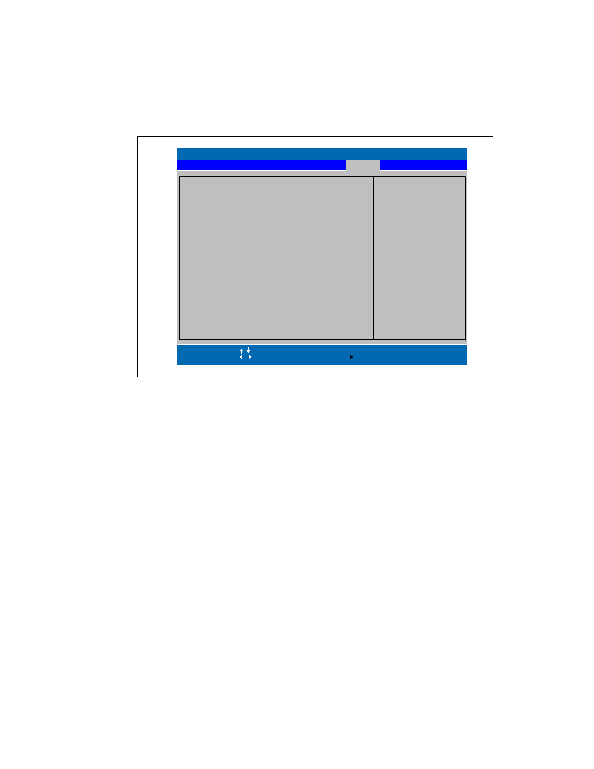
Configuring the SIMATIC Field PG
Groups marked + can contain more than one device. When you select a group
marked in this way, hit Enter to view the list of devices in the group. See the figure
below for an illustration:
–Removable Devices
LS-120 SLIM4 00–(SM)
–Hard Drive
FUJITSU MHM2100AT–(PM)
Alternate Device
CD–ROM Drive
Network Boot
PhoenixBIOS Setup Utility
Advanced Security Version ExitMain Power
Boot
Item Specific Help
Keys used to view or
configure devices:
<Enter> expands or
collapses devices with
a + or –
<Ctrl+Enter> expands
all
<+> and <–> moves
the device up or down.
Help
F1
ESC Exit
Select Item
Select Menu
+ / –
Enter
Change Values
Select
Sub-MenuF9F10
Setup Defaults
Save and Exit
Fig. 5-14 The “Boot” Menu
This screen shows all possible boot devices; within a given group the highest
priority device is always listed first. Here again, you can change the sequence as
described above.
If a boot device is not available, the next device in the sequence is automatically
checked to ascertain whether or not it is bootable.
5-20
SIMATIC Field PG Manual
A5E00075760-04
Page 87
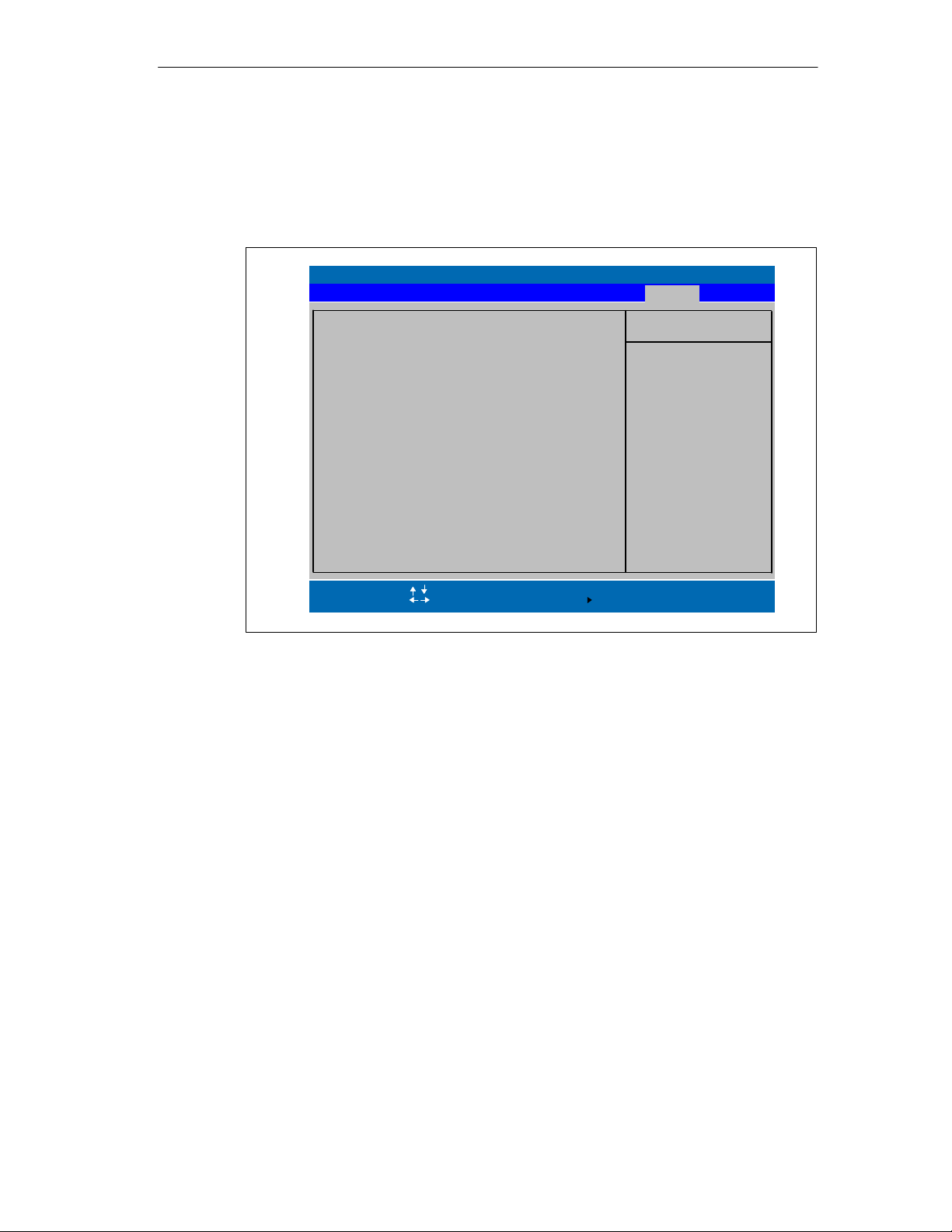
5.7 The Version Menu
This menu contains the information you will have to quote when you send us
technical questions about your system.
Advanced Security ExitMain Power
SIMATIC PG
Bios Version
Bios Number
MPI/DP Firmware
ProgAS Firmware
EC Firmware Vxx
PhoenixBIOS Setup Utility
Field PG
Vxx.xx.xx
A5E000xxxxx-ESxx
Vxx
Vxx
Configuring the SIMATIC Field PG
Boot
Version
Item Specific Help
All items on this menu
cannot be modified in
user mode. If any
items require changes,
please consult your
system Supervisor.
CPU Type
CPU Speed
CPU ID
Code Revision
Help
F1
ESC Exit
Fig. 5-15 The ”Version” Menu
Pentium(R) III
550 MHz
0683
0007
Select Item
Select Menu
+ / -
Enter
Change Values
Select
Sub-MenuF9F10
Setup Defaults
Save and Exit
SIMATIC Field PG Manual
A5E00075760-04
5-21
Page 88
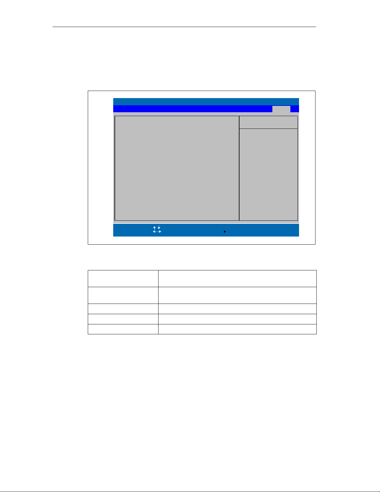
Configuring the SIMATIC Field PG
5.8 The Exit Menu
The setup program is always terminated using this menu.
Save Changes & Exit
Exit Without Saving Changes
Get Default Values
Load Previous Values
Save Changes
PhoenixBIOS Setup Utility
Advanced SecurityMain Power
Boot
Version
Item Specific Help
Exit System Setup and
save your change to
CMOS.
Exit
Help
F1
ESC Exit
Fig. 5-16 The ”Exit” Menu
Save Changes & Exit All changes are saved; a system restart is carried out with the
Discard Changes & Exit All changes are rejected; a system restart is carried out with
Get Default Values All parameters are set to safe values.
Load Previous Values The last saved values are reloaded.
Save Changes Save all Setup settings.
Select Item
Select Menu
+ / -
Enter
Change Values
Select
new parameters.
the previous parameters.
Sub-MenuF9F10
Setup Defaults
Save and Exit
5-22
SIMATIC Field PG Manual
A5E00075760-04
Page 89

Error Diagnostics
6
What Does This Chapter Contain?
This chapter will help you to locate, identify, and in some cases eliminate simple
errors and faults.
Error/Fault Remedy
Device LED does not light up
• PG is switched off
• Power supply not properly connected
• Battery run down or not installed
External monitor remains dark
• LCD enabled is entered in SETUP • Enter CRT enabled or SIMULTANEOUS in SETUP
Message on the Display :”Invalid configuration information... Press the F1 key for continue, F2 to
run Setup utility”
• Configuration data not correct • Hit the “F2” key, check the configuration data in the
Message on the Display ”No boot device available” NTLDR not found, check boot data carrier
• No bootable disk in drive A:
• Wrong hard disk type entered in SETUP
Message on the Display : ”Keyboard stuck key failure”
• A key became blocked during the self-test of
the keyboard
Every time a key is pressed, a beep is heard and no characters are displayed
• Keyboard buffer overflow
< \ > key does not exist
• Wrong keyboard driver • German keyboard: <ALTGr> <ß>
After power on: error message: “Battery needs calibration cycle”
• Battery is no longer calibrated • Confirm error message with the “F1” key
• Press the Power Button
• Check the power supply, power cable, and power
plug
• Charge or install the battery
SETUP program, if necessary adapt the default
values, check the error messages in the first SETUP menu
• Replace the disk with a boot disk
• Use the “Autodetect Fixed Disk” function
• Check the keyboard. Restart the system if need be.
• <CTRL> <PAUSE>
• International keyboard : <\> key
• Run a teach-in cycle
SIMATIC Field PG Manual
A5E00075760-04
6-1
Page 90

Error Diagnostics
6-2
SIMATIC Field PG Manual
A5E00075760-04
Page 91

Hardware Information
Chapter Overview
Section Description Page
7.1 System resources 7-2
7.2 Interface pinout 7-3
7.3 Cables 7-10
7
SIMATIC Field PG Manual
A5E00075760-04
7-1
Page 92

Hardware Information
7.1 System Resources
All system resources (hardware address, memory configuration, IRQ,
DMA channel) are assigned dynamically by the Windows OS, depending on the
hardware configuration, drivers and connected peripheral devices. You can view
the current configuration of system resources or possible conflicts with the
following operating systems:
Windows Me
Start > Programs > Accessories > System Tools > System Information
Windows 2000
Start > Settings > Control Panel > Administrative Tools > Computer
Management > System Information
7-2
SIMATIC Field PG Manual
A5E00075760-04
Page 93
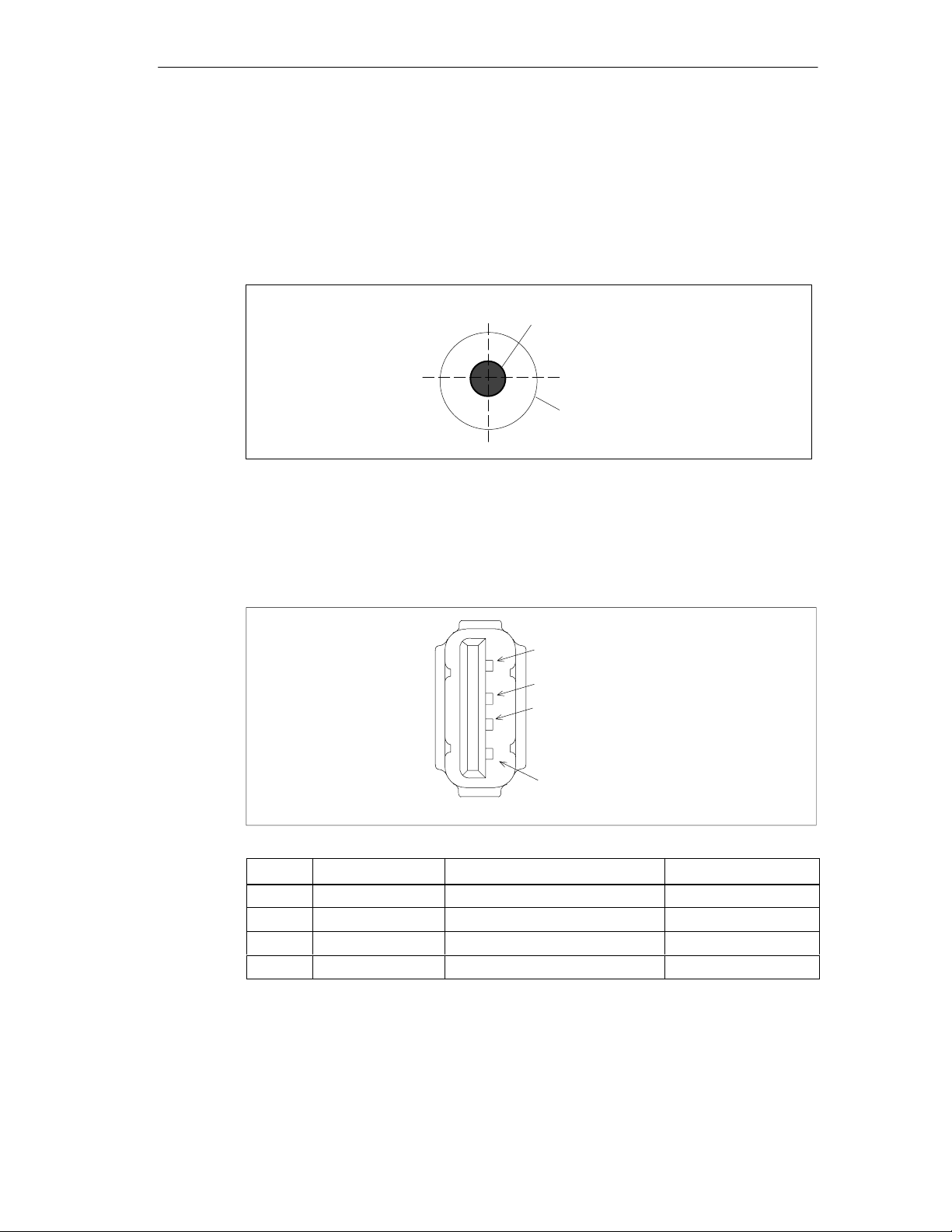
7.2 Interface Pinout
DC-In
Jack for connecting the AC/DC adapter. Potentials:
Hardware Information
+ 17.5 VDC
0 V Ground
USB
Both interfaces are conceived for high-current USB (500mA). However, they
cannot be used simultaneously as high-current interface.
4
3
2
1
Pin-No. Designation Description Input / Output
1 VCC +5V (fused) Output
2 - Data Data line Input / Output
3 + Data Data line Input / Output
4 GND Ground -
SIMATIC Field PG Manual
A5E00075760-04
7-3
Page 94
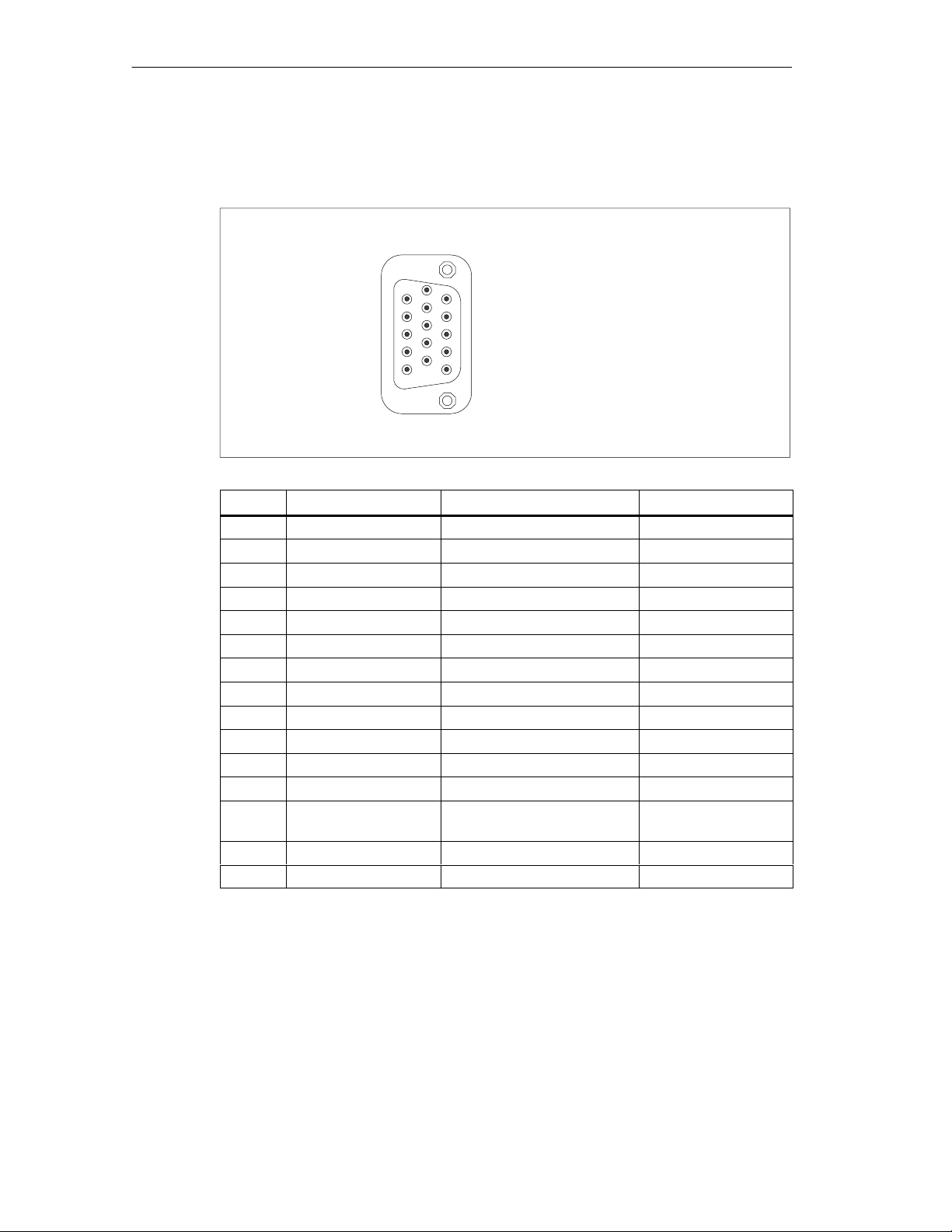
Hardware Information
VGA
15-pole socket for an external monitor. Pinout:
Pin No. Designation Description Input/Output
1 R Red Output
2 G Green Output
3 B Blue Output
4 - Unassigned 5 GND Ground 6 GND Ground 7 GND Ground 8 GND Ground 9 - Unassigned 10 GND Ground 11 - Unassigned 12 DDC_DAT Display Data Channel Data Input / Output
13 EXT_H Horizontal synchronizing
14 EXT_V Vertical synchronizing pulse Output
15 DDC_CLK Display Data Channel Clock Input / Output
6
1
5
11
10
15
Output
pulse
7-4
SIMATIC Field PG Manual
A5E00075760-04
Page 95
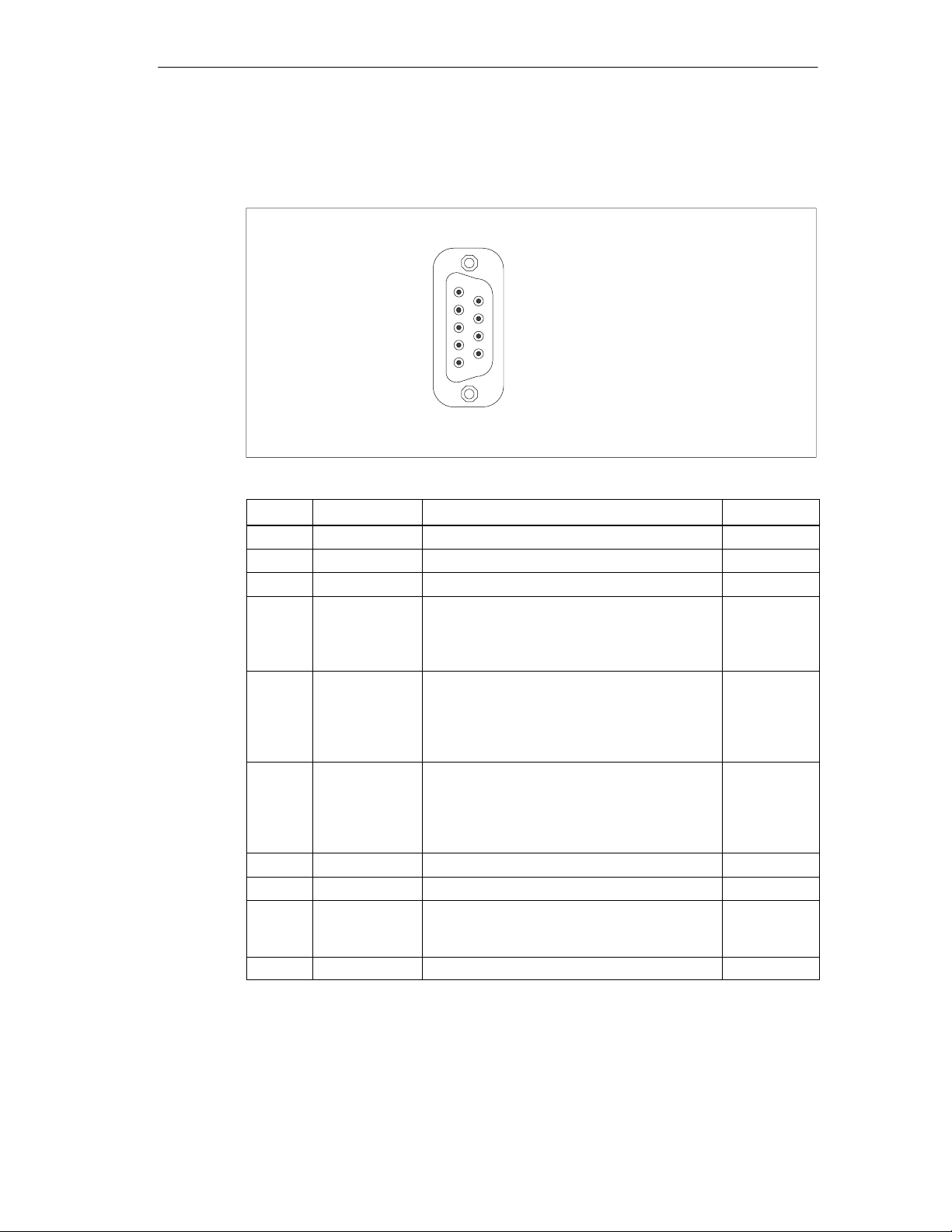
MPI/DP
Pinout of the MPI/DP socket:
Hardware Information
1
6
9
5
Pin No. Designation Description Input/Output
1 - Unassigned 2 - Unassigned 3 LTG_B Signal line B of MPI module Input/output
4 RTS_AS RTSAS, control signal for received data
Input
stream. The signal is “1” active when the
directly connected programmable controller is
sending.
5 M5EXT M5EXT return line (GND) of the 5 V power
Output
supply. The current load caused by an
external user connected between P5EXT and
M5EXT must not exceed the maximum of
90 mA.
6 P5 EXT P5EXT power supply (+5 V) of the 5 V power
Output
supply. The current load caused by an
external user connected between P5EXT and
M5EXT must not exceed the maximum of
90 mA.
7 - Unassigned 8 LTG_A Signal line A of the MPI module Input/output
9 RTS_PG RTS output signal of the MPI module. The
Output
control signal is “1” when the programming
device is sending.
Screen on connector casing
SIMATIC Field PG Manual
A5E00075760-04
7-5
Page 96
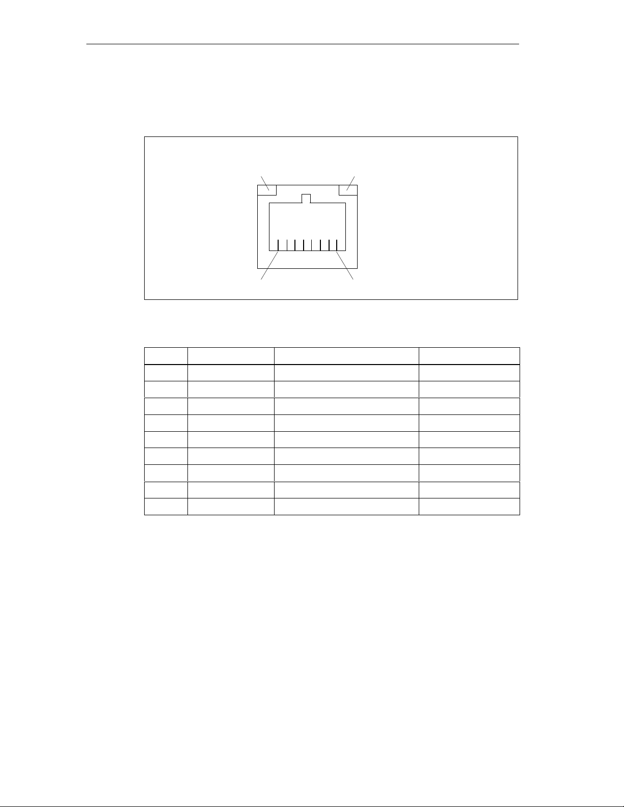
Hardware Information
Ethernet
Pinout of the Ethernet interface:
Fig. 7-1 Ethernet port
LED greenLED yellow
1 8
Pin-No.
1 TD+ Transmitted data Output
2 TD– Transmitted data Output
3 RD+ Received data Input
4, 5 * SYMR Internal 75 Ω output 6 Received data Input
7, 8 * SYMT Internal 75 Ω output S Shield -
Designation Description Input / Output
LED yellow Connection LED green Activity -
* is not necessary for data transfer
7-6
SIMATIC Field PG Manual
A5E00075760-04
Page 97
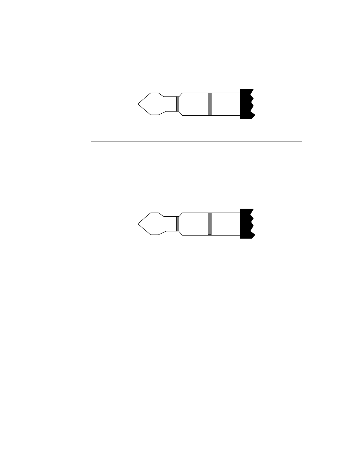
Micro-In
Hardware Information
Plug for external microphone. Pinout:
Headphone
NF
3.5-mm Microphone phono plug
Fig. 7-2 Microphone
Plug for external headphones. Pinout:
Left
3.5-mm Stereo phono plug
Fig. 7-3 Headphone
Right GND
MicPower
Mic
ground
SIMATIC Field PG Manual
A5E00075760-04
7-7
Page 98
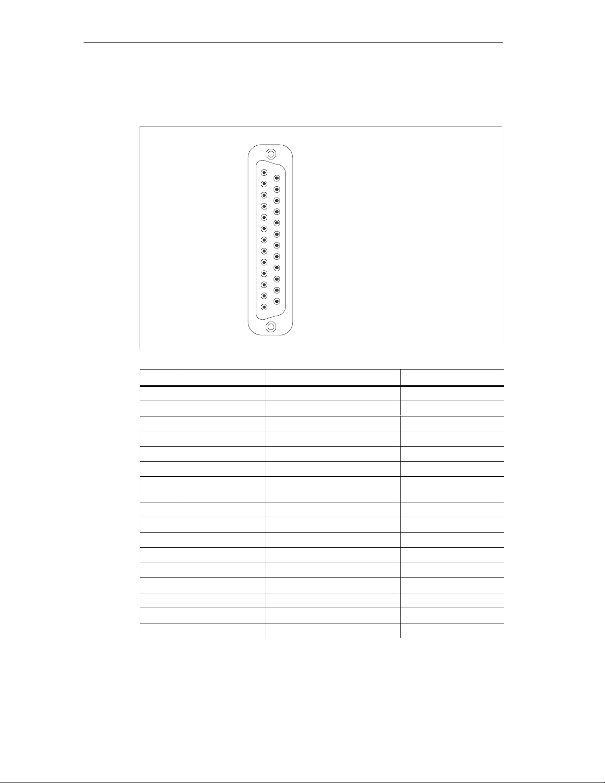
Hardware Information
COM1 (V.24/TTY)
Serial interface COM1 (AG/V.24/Modem). Pinout:
13
1
14
25
Pin No. Designation Description Input /Output
1 - Shield 2 TxD (D1) Serial transmit data Output
3 RxD (D2) Serial receive data Input
4 RTS (S2) Request to send Output
5 CTS (M2) Clear to send Input
6 DSR (M1) Data set ready Input
7 GND (E2) Functional ground
-
(reference potential)
8 DCD (M5) Data carrier detect Input
9 +TTY RxD TTY receive Input
10 - 17 - Unassigned 18 +TTY TxD TTY send Output
19 +20mA Isolated current source 20 DTR (S1) Data terminal ready Output
21 -TTY TxD TTY send Output
22 RI (M3) Incoming call Input
23-25 - Unassigned -
7-8
SIMATIC Field PG Manual
A5E00075760-04
Page 99

Gender Changer for COM1
Use the Gender Changer (25-pin / 9-pin) to convert your COM1/ V24 / PLC
interface to a common 9-pole pin strip. Just plug the Gender Changer into the
COM1 socket and secure it with the two hex head screws.
The V24 and TTY interfaces for COM1 can be alternately used.
Hardware Information
SIMATIC Field PG Manual
A5E00075760-04
7-9
Page 100
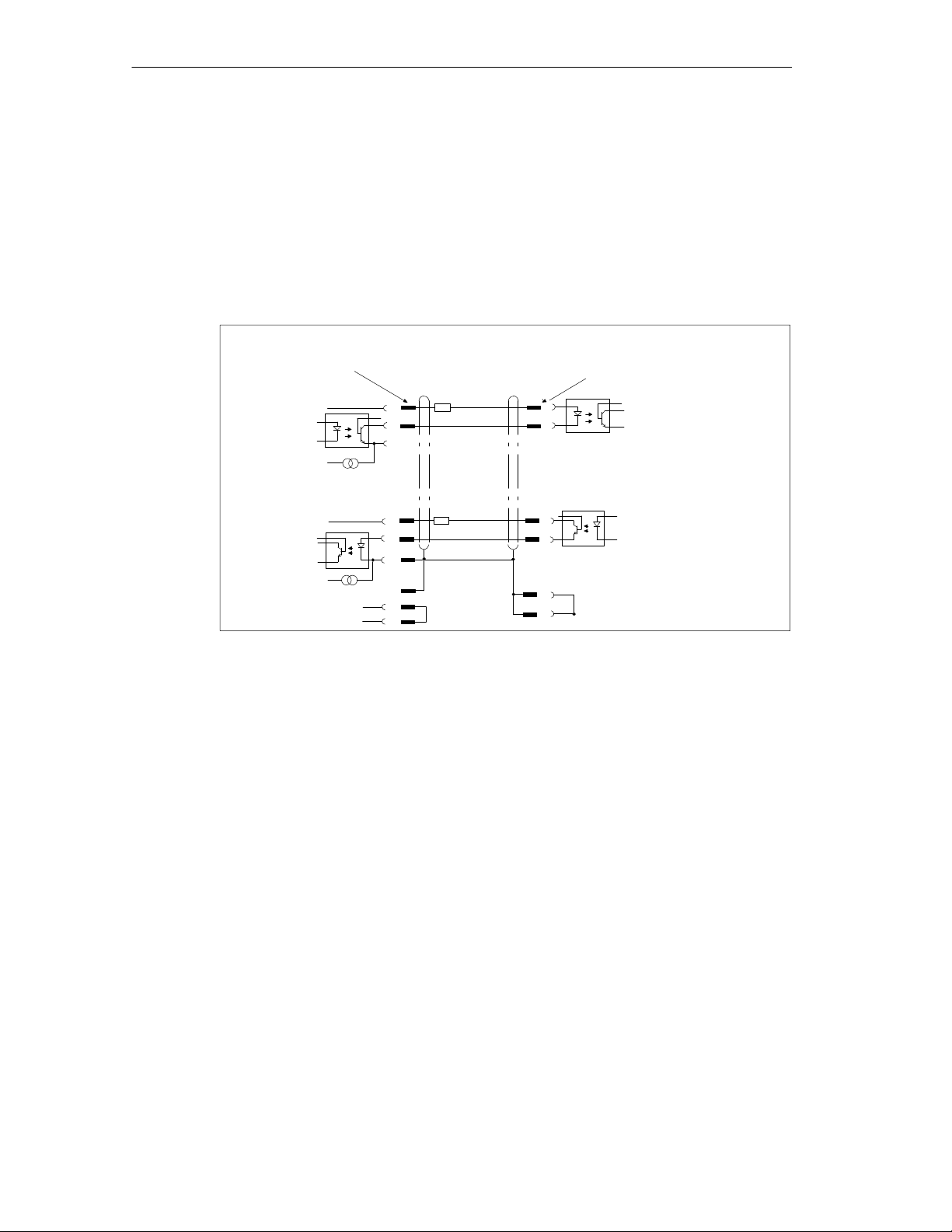
Hardware Information
7.3 Patch Cords
SIMATIC S5 Patch Cord
You can use the SIMATIC S5 cord set (not included in all delivered versions) to
connect your SIMATIC Field PG to a SIMATIC S5 PLC. Please not the comments
in Chapter 3.
PG side
25–pole pin strip
active
+V
–V
+V
–V
Housing
Fig. 7-4 SIMATIC S5 Standard Cord Set
MPI/DP Cord Set for SIMATIC S7
You can use the 6ES7901-0BF00-0AA0 cord set to connect your
SIMATIC Field PG to a SIMATIC S7 PLC. Please not the comments in Chapter 3.
Patch cord
6ES5 734-2BD20
(included in the consignment)
330 Ohm
19
18
21
330 Ohm
19
9
10
1
3
20
PLC side
15–pole pin strip
passiv
9
2
6
7
8
1
Shielding/
Housing
7-10
SIMATIC Field PG Manual
A5E00075760-04
 Loading...