

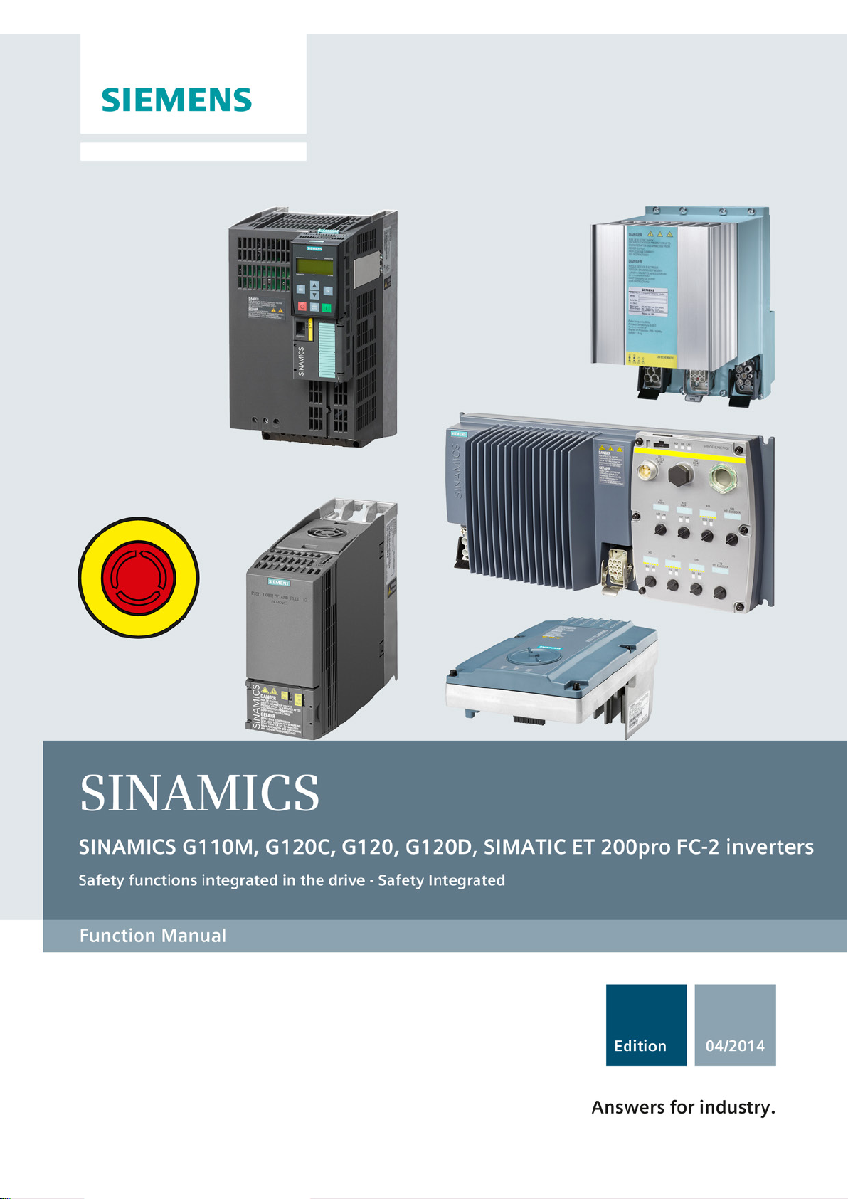
Siemens SINAMICS G120, SINAMICS G110M, SINAMICS G120C, SINAMICS G120D, SIMATIC ET 200pro FC-2 Function Manual
Page 1
Page 2

Page 3
Safety Integrated - SINAMICS G110M,
G120, G120C, G120D and SIMATIC ET
200pro FC-2
___________________
___________________
___________________
___________________
___________________
___________________
___________________
___________________
___________________
___________________
SINAMICS
SINAMICS G120
Safety Integrated - SINAMICS
G110M, G120, G120C, G120D and
SIMATIC ET 200pro FC-2
Function Manual
Edition 04/2014, firmware V4.7
04/2014, FW V4.7
A5E34261271B AA
Change history
Fundamental safety
instructions
1
Introduction
2
Description
3
Installing
4
Commissioning
5
Operation
6
Corrective maintenance
7
System properties
8
Appendix
A
Page 4

Siemens AG
Industry Sector
Postfach 48 48
90026 NÜRNBERG
GERMANY
A5E34261271B AA
Ⓟ
Copyright © Siemens AG 2010 - 2014.
All rights reserved
Legal information
Warning notice system
DANGER
indicates that death or severe personal injury will result if proper precautions are not taken.
WARNING
indicates that death or severe personal injury may result if proper precautions are not taken.
CAUTION
indicates that minor personal injury can result if proper precautions are not taken.
NOTICE
indicates that property damage can result if proper precautions are not taken.
Qualified Personnel
personnel qualified
Proper use of Siemens products
WARNING
Siemens products may only be used for the applications described in the catalog and in the relevant technical
maintenance are required to ensure that the products operate safely and without any problems. The permissible
ambient conditions must be complied with. The information in the relevant documentation must be observed.
Trademarks
Disclaimer of Liability
This manual contains notices you have to observe in order to ensure your personal safety, as well as to prevent
damage to property. The notices referring to your personal safety are highlighted in the manual by a safety alert
symbol, notices referring only to property damage have no safety alert symbol. These notices shown below are
graded according to the degree of danger.
If more than one degree of danger is present, the warning notice representing the highest degree of danger will
be used. A notice warning of injury to persons with a safety alert symbol may also include a warning relating to
property damage.
The product/system described in this documentation may be operated only by
task in accordance with the relevant documentation, in particular its warning notices and safety instructions.
Qualified personnel are those who, based on their training and experience, are capable of identifying risks and
avoiding potential hazards when working with these products/systems.
for the specific
Note the following:
documentation. If products and components from other manufacturers are used, these must be recommended
or approved by Siemens. Proper transport, storage, installation, assembly, commissioning, operation and
All names identified by ® are registered trademarks of Siemens AG. The remaining trademarks in this publication
may be trademarks whose use by third parties for their own purposes could violate the rights of the owner.
We have reviewed the contents of this publication to ensure consistency with the hardware and software
described. Since variance cannot be precluded entirely, we cannot guarantee full consistency. However, the
information in this publication is reviewed regularly and any necessary corrections are included in subsequent
editions.
07/2014 Subject to change
Page 5

Change history
Important changes with respect to the Manual, Edition 01/2013
New functions in firmware V4.7
In Chapter
---
---
Corrections
In Chapter
selecting STO, however, not after a power-on reset.
(Page 162)
functions) has been corrected.
(basic functions) (Page 47)
Connecting an actuator without feedback signal to the safety
removed.
bus cycle time).
When debounce time = 0: t_E = 4 ms instead of 2 ms
Supplements and revised descriptions
In Chapter
Installing (Page 41)
Installing (Page 41)
safety functions have been revised.
functions is now sorted according to functions.
(Page 161)
The "Startdrive" commissioning tool is mentioned.
Commissioning tools (Page 84)
The forced checking procedure (test stop) starts after
Assignment of the signal states in control word 1, bit 0 (basis
output of the SINAMICS G120 with CU250S-2 does not
comply with SIL 2. The connection example has been
The worst-case response times for the extended STO
function have been corrected for an inverter fault/error:
When controlled via PROFIBUS: 56 ms instead of 58 ms.
When controlled via PROFINET: 56 ms instead of 58 ms (+
Worst-case response time for the STO basis function when
controlled via a safety input has been corrected: 6 ms + t_E
instead of 14 ms + t_E.
Worst-case response time for the extended STO function
when controlled via a safety input: 52 ms + t_E instead of
54 ms + t_E.
When debounce time > 0: t_E =debounce time + 3 ms
instead of debounce time + 1 ms
Testing the basic functions
Control word 1 and status word 1
Connecting the safety output for
SINAMICS G120 (Page 73)
Response times (Page 269)
New SINAMICS G110M inverters Description (Page 19)
New SIMATIC ET 200pro FC-2 inverter Description (Page 19)
Overview, preconditions and restrictions when using the
The description of the time response of active safety
The test of the safety inputs has been supplemented. Regularly testing the safety functions
Safety Integrated - SINAMICS G110M, G120, G120C, G120D and SIMATIC ET 200pro FC-2
Function Manual, 04/2014, FW V4.7, A5E34261271B AA
Description (Page 19)
Operation (Page 159)
5
Page 6

Change history
Supplements and revised descriptions
In Chapter
functions (PFH value) (Page 267)
control (Page 176)
The probability of failure PFD has been supplemented. Probability of failure of the safety
Error response of the SBC function has been supplemented. Response to faults in the brake
Safety Integrated - SINAMICS G110M, G120, G120C, G120D and SIMATIC ET 200pro FC-2
6 Function Manual, 04/2014, FW V4.7, A5E34261271B AA
Page 7

Table of contents
Change history ........................................................................................................................................ 5
1 Fundamental safety instructions ............................................................................................................ 13
2 Introduction ........................................................................................................................................... 15
3 Description ............................................................................................................................................ 19
4 Installing ............................................................................................................................................... 41
1.1 General safety instructions .......................................................................................................... 13
1.2 Industrial security ......................................................................................................................... 14
2.1 About this manual ........................................................................................................................ 15
2.2 Guide through the manual ........................................................................................................... 18
3.1 About this chapter ........................................................................................................................ 19
3.2 Overview of the safety functions .................................................................................................. 19
3.3 Overview of the safety-related inverter interfaces ....................................................................... 21
3.4 Preconditions when using the safety functions ............................................................................ 22
3.5 Restrictions when using safety functions ..................................................................................... 23
3.6 Recommendations for stable operation ....................................................................................... 26
3.7 Safe Torque Off (STO) ................................................................................................................. 27
3.8 Safe Brake Control (SBC) ............................................................................................................ 30
3.9 Safe Stop 1 (SS1) ........................................................................................................................ 32
3.10 Safely Limited Speed (SLS) ......................................................................................................... 34
3.11 Safe Direction (SDI) ..................................................................................................................... 37
3.12 Safe Speed Monitoring (SSM) ..................................................................................................... 39
4.1 Installing the inverter .................................................................................................................... 41
4.2 Connection via PROFIsafe .......................................................................................................... 42
4.2.1 Overview of PROFIsafe connections ........................................................................................... 42
4.2.2 PROFIsafe telegrams .................................................................................................................. 46
4.2.3 Control word 1 and status word 1 (basic functions) ..................................................................... 47
4.2.4 Control word 1 and status word 1 (extended functions) .............................................................. 48
4.2.5 Control word 5 and status word 5 ................................................................................................ 50
4.3 Activation via F-DI ........................................................................................................................ 51
4.3.1 Safety inputs ................................................................................................................................ 51
4.3.2 Wiring examples........................................................................................................................... 54
4.3.2.1 Connecting sensors ..................................................................................................................... 54
4.3.2.2 Connecting pre-processing devices ............................................................................................. 62
4.4 Evaluating via F-DO ..................................................................................................................... 71
Safety Integrated - SINAMICS G110M, G120, G120C, G120D and SIMATIC ET 200pro FC-2
Function Manual, 04/2014, FW V4.7, A5E34261271B AA
7
Page 8

Table of contents
5 Commissioning ..................................................................................................................................... 77
4.4.1 Safety output ............................................................................................................................... 71
4.4.2 Connecting the safety output for SINAMICS G120D .................................................................. 72
4.4.3 Connecting the safety output for SINAMICS G120 ..................................................................... 73
4.5 Connecting a motor holding brake to a Safe Brake Relay .......................................................... 74
5.1 Commissioning guidelines .......................................................................................................... 77
5.2 Configure PROFIsafe in the higher-level control system ............................................................ 78
5.2.1 Configuring PROFIBUS communication with telegram 30 via GSD ........................................... 78
5.2.2 Example: Interface to the S7 safety program .............................................................................. 80
5.2.3 Configuring PROFIBUS communication via telegram 900 with the GSDML .............................. 82
5.2.4 Configuring shared device communication via PROFINET ........................................................ 82
5.3 Commissioning tools ................................................................................................................... 84
5.4 Resetting the safety function parameters to the factory setting .................................................. 85
5.5 Changing settings ....................................................................................................................... 86
5.6 Setting basic functions ................................................................................................................ 90
5.6.1 Interconnecting the "STO active" signal ...................................................................................... 91
5.6.2 Configuring PROFIsafe ............................................................................................................... 92
5.6.3 Setting the filter for safety inputs ................................................................................................. 94
5.6.4 Setting the forced checking procedure (test stop) ...................................................................... 98
5.6.5 Setting the delay time for SS1 .................................................................................................... 99
5.6.6 Enabling SBC ............................................................................................................................ 100
5.6.7 Final steps ................................................................................................................................. 101
5.7 Setting extended functions ........................................................................................................ 103
5.7.1 Basic settings ............................................................................................................................ 104
5.7.1.1 Enabling safety functions .......................................................................................................... 104
5.7.1.2 Setting the forced dormant error detection (test stop) .............................................................. 104
5.7.1.3 Setting the gear ratio and actual value tolerance...................................................................... 107
5.7.1.4 Setting encoderless actual value sensing ................................................................................. 109
5.7.2 Setting safety inputs .................................................................................................................. 111
5.7.2.1 Setting the filter for safety inputs ............................................................................................... 113
5.7.2.2 Interconnecting the signal for fail-safe acknowledgment .......................................................... 119
5.7.3 Setting a safety output .............................................................................................................. 120
5.7.3.1 Output signal and setting the test mode ................................................................................... 120
5.7.3.2 Setting the forced dormant error detection (test stop) .............................................................. 125
5.7.4 Configuring PROFIsafe in the converter ................................................................................... 127
5.7.5 Setting SS1 ............................................................................................................................... 130
5.7.5.1 Setting SS1 with braking ramp monitoring ................................................................................ 131
5.7.5.2 Setting SS1 with acceleration monitoring ................................................................................. 134
5.7.6 Setting SLS ............................................................................................................................... 137
5.7.6.1 Setting the monitoring functions ................................................................................................ 137
5.7.6.2 Settings for acceptance test ...................................................................................................... 141
5.7.7 Setting SSM .............................................................................................................................. 142
5.7.8 Setting SDI ................................................................................................................................ 146
5.7.8.1
Setting the monitoring functions ................................................................................................ 146
5.7.8.2 Settings for acceptance test ...................................................................................................... 149
5.7.9 Final steps ................................................................................................................................. 150
5.8 Offline commissioning ............................................................................................................... 153
Safety Integrated - SINAMICS G110M, G120, G120C, G120D and SIMATIC ET 200pro FC-2
8 Function Manual, 04/2014, FW V4.7, A5E34261271B AA
Page 9

Table of contents
6 Operation ............................................................................................................................................ 159
5.9 Series commissioning ................................................................................................................ 155
5.10 Acceptance tests for the safety functions .................................................................................. 156
5.10.1 Acceptance test.......................................................................................................................... 156
5.10.2 Reduced acceptance test after expanding the function ............................................................. 158
6.1 Overview and relevant inverter signals ...................................................................................... 159
6.2 Regularly testing the safety functions ........................................................................................ 161
6.2.1 Overview .................................................................................................................................... 161
6.2.2 Testing safety inputs .................................................................................................................. 161
6.2.3 Testing the basic functions ........................................................................................................ 162
6.2.4 Testing the extended functions .................................................................................................. 163
6.2.5 Testing a safety output ............................................................................................................... 165
6.3 Safe Torque Off (STO) ............................................................................................................... 168
6.3.1 Overview .................................................................................................................................... 168
6.3.2 Selecting and deselecting STO when the motor is switched on ................................................ 169
6.3.3 Response to a discrepancy when STO is active ....................................................................... 170
6.4 Safe Brake Control (SBC) .......................................................................................................... 173
6.4.1 Selecting and deselecting SBC when the motor is switched on ................................................ 173
6.4.2 Response to faults in the brake control ..................................................................................... 176
6.5 Safe Stop 1 (SS1) ...................................................................................................................... 177
6.5.1 Overview .................................................................................................................................... 177
6.5.2 Selecting and deselecting SS1 when the motor is switched on ................................................ 178
6.5.2.1 SS1 without monitoring .............................................................................................................. 178
6.5.2.2 SS1 with braking ramp monitoring ............................................................................................. 179
6.5.2.3 SS1 with acceleration monitoring ............................................................................................... 180
6.5.3 Switching off the motor when SS1 is active ............................................................................... 182
6.5.4 Response to a discrepancy when SS1 is active ........................................................................ 183
6.5.5 Limit value violation when SS1 is active .................................................................................... 187
6.6 Safely Limited Speed (SLS) ....................................................................................................... 188
6.6.1 Overview .................................................................................................................................... 188
6.6.2 Selecting and deselecting SLS when the motor is switched on ................................................ 189
6.6.2.1 SLS with braking ramp monitoring ............................................................................................. 191
6.6.2.2 SLS without braking ramp monitoring ........................................................................................ 193
6.6.3 Switching over SLS levels .......................................................................................................... 195
6.6.3.1 SLS with braking ramp monitoring ............................................................................................. 196
6.6.3.2 SLS without braking ramp monitoring ........................................................................................ 198
6.6.4 Switching off the motor when SLS is active ............................................................................... 199
6.6.5 Switching on the motor when SLS is active ............................................................................... 201
6.6.6 Response to a discrepancy when SLS is active ........................................................................ 202
6.6.7 Limit value violation when SLS is active .................................................................................... 204
6.7 Safe Speed Monitor (SSM) ........................................................................................................ 206
6.7.1 Overview .................................................................................................................................... 206
6.7.2 Selecting SSM when the motor is switched on
.......................................................................... 207
6.7.3 Switching off the motor when SSM is active .............................................................................. 208
6.7.4 Switching on the motor when SSM is active .............................................................................. 213
6.8 Safe Direction (SDI) ................................................................................................................... 215
6.8.1 Overview .................................................................................................................................... 215
Safety Integrated - SINAMICS G110M, G120, G120C, G120D and SIMATIC ET 200pro FC-2
Function Manual, 04/2014, FW V4.7, A5E34261271B AA
9
Page 10

Table of contents
7 Corrective maintenance ....................................................................................................................... 251
8 System properties ................................................................................................................................ 267
A Appendix ............................................................................................................................................. 277
6.8.2 Selecting and deselecting SDI when the motor is switched on ................................................ 216
6.8.3 Switching off the motor when SDI is active ............................................................................... 217
6.8.4 Switching on the motor when SDI is active ............................................................................... 219
6.8.5 Response to a discrepancy when Safe Direction is active (SDI) .............................................. 221
6.8.6 Limit value violation when Safe Direction (SDI) is active .......................................................... 223
6.9 Response to a discrepancy in the signals transferred via PROFIsafe ..................................... 225
6.10 Stop responses ......................................................................................................................... 227
6.10.1 Example 1: Internal event with STO active ............................................................................... 229
6.10.2 Example 2: Internal event with SSM active ............................................................................... 230
6.11 Fail-safe acknowledgment signal .............................................................................................. 232
6.11.1 Acknowledging using a fail-safe signal ..................................................................................... 232
6.11.2 Response to a discrepancy of the fail-safe acknowledge signal .............................................. 233
6.12 Selecting safety function when a safety function is active ........................................................ 234
6.13 List of alarms and faults ............................................................................................................ 242
7.1 Maintaining operational safety .................................................................................................. 251
7.2 Replacing components of the modular SINAMICS G120/G120D/G110M inverters ................. 253
7.2.1 Overview of replacing converter components ........................................................................... 253
7.2.2 Replacing a Control Unit with enabled safety function ............................................................. 255
7.2.3 Replacing the Control Unit without data backup ....................................................................... 258
7.2.4 Replacing a Power Module with enabled safety function ......................................................... 259
7.3 Replacing SINAMICS G120C inverters or SIMATIC ET 200pro FC-2 converters .................... 260
7.3.1 Overview of how to replace an inverter ..................................................................................... 260
7.3.2 Replacing a converter with enabled safety function ................................................................. 261
7.3.3 Replacing a converter without data backup .............................................................................. 265
7.4 Reduced acceptance test after component replacement ......................................................... 266
8.1 Probability of failure of the safety functions (PFH value) .......................................................... 267
8.2 Response times ........................................................................................................................ 269
8.3 Certification ............................................................................................................................... 273
8.4 Safe Brake Relay ...................................................................................................................... 275
A.1 Examples of acceptance tests .................................................................................................. 277
A.1.1 Acceptance test STO (basic functions) ..................................................................................... 278
A.1.2 Acceptance test STO (extended functions) .............................................................................. 280
A.1.3 SS1 acceptance test (basic functions) ...................................................................................... 282
A.1.4 SS1 acceptance test (extended functions) ............................................................................... 284
A.1.5 SBC acceptance test ................................................................................................................. 288
A.1.6 Acceptance test SLS ................................................................................................................. 290
A.1.7 SSM acceptance test ................................................................................................................ 295
A.1.8 Acceptance test SDI .................................................................................................................. 299
A.1.9 Acceptance test for F-DI status in PROFIsafe telegram 900 .................................................... 308
A.2 Documentation for acceptance ................................................................................................. 309
Safety Integrated - SINAMICS G110M, G120, G120C, G120D and SIMATIC ET 200pro FC-2
10 Function Manual, 04/2014, FW V4.7, A5E34261271B AA
Page 11

Table of contents
Index................................................................................................................................................... 339
A.2.1 Creating logs with the settings of the safety functions ............................................................... 309
A.2.2 Example of machine documentation .......................................................................................... 311
A.2.3 Log the settings for the basic functions, firmware V4.4 ... V4.7 ................................................. 313
A.2.4 Log the settings for the extended functions, firmware V4.4 ... V4.7 .......................................... 314
A.3 Standards and specifications ..................................................................................................... 317
A.3.1 General information ................................................................................................................... 317
A.3.1.1 Aims ........................................................................................................................................... 317
A.3.1.2 Functional safety ........................................................................................................................ 317
A.3.2 Safety of machinery in Europe ................................................................................................... 319
A.3.2.1 Machinery Directive ................................................................................................................... 319
A.3.2.2 Harmonized European Standards.............................................................................................. 319
A.3.2.3 Standards for implementing safety-related controllers .............................................................. 321
A.3.2.4 DIN EN ISO 13849-1 (replaces EN 954-1) ................................................................................ 322
A.3.2.5 EN 62061 ................................................................................................................................... 323
A.3.2.6 Series of standards IEC 61508 (VDE 0803) .............................................................................. 325
A.3.2.7 Risk analysis/assessment .......................................................................................................... 326
A.3.2.8 Risk reduction ............................................................................................................................ 327
A.3.2.9 Residual risk ............................................................................................................................... 328
A.3.3 Machine safety in the USA ......................................................................................................... 329
A.3.3.1 Minimum requirements of the OSHA ......................................................................................... 329
A.3.3.2 NRTL listing ................................................................................................................................ 329
A.3.3.3 NFPA 79 ..................................................................................................................................... 330
A.3.3.4 ANSI B11 ................................................................................................................................... 330
A.3.4 Machine safety in Japan ............................................................................................................ 331
A.3.5 Equipment regulations ............................................................................................................... 332
A.3.6 Other safety-related issues ........................................................................................................ 333
A.3.6.1 Additional references ................................................................................................................. 333
A.3.6.2 Information sheets issued by the Employer's Liability Insurance Association ........................... 333
A.4 Manuals and technical support .................................................................................................. 334
A.4.1 Manuals for your inverter ........................................................................................................... 334
A.4.2 Configuring support .................................................................................................................... 336
A.4.3 Product Support ......................................................................................................................... 337
A.5 Mistakes and improvements ...................................................................................................... 338
Safety Integrated - SINAMICS G110M, G120, G120C, G120D and SIMATIC ET 200pro FC-2
Function Manual, 04/2014, FW V4.7, A5E34261271B AA
11
Page 12

Table of contents
Safety Integrated - SINAMICS G110M, G120, G120C, G120D and SIMATIC ET 200pro FC-2
12 Function Manual, 04/2014, FW V4.7, A5E34261271B AA
Page 13
1
1.1
General safety instructions
WARNING
Risk of death if the safety instructions and remaining risks are not carefully observed
WARNING
Danger to life or malfunctions of the machine as a result of incorrect or changed
parameterization
If the safety instructions and residual risks are not observed in the associated hardware
documentation, accidents involving severe injuries or death can occur.
• Observe the safety instructions given in the hardware documentation.
• Consider the residual risks for the risk evaluation.
As a result of incorrect or changed parameterization, machines can malfunction, which in
turn can lead to injuries or death.
• Protect the parameterization (parameter assignments) against unauthorized access.
• Respond to possible malfunctions by applying suitable measures (e.g. EMERGENCY
STOP or EMERGENCY OFF).
Safety Integrated - SINAMICS G110M, G120, G120C, G120D and SIMATIC ET 200pro FC-2
Function Manual, 04/2014, FW V4.7, A5E34261271B AA
13
Page 14
Fundamental safety instructions
1.2
Industrial security
Note
Industrial security
Siemens provides products and solutions with industrial security functions that support the
secure operation of plants, solutions, machines, equipment and/or networks. They are
important components in a holistic industrial security concept. With this in mind, Siemens’
products and solutions undergo continuous development. Siemens recommends strongly that
you regularly check for product updates.
For the secure operation of Siemens
preventive action (e.g. cell protection concept) and integrate each component into a holistic,
state
also be co
(
To stay informed about product updates as they occur, sign up for a
newsletter. For more information, visit Hotspot
).
WARNING
Danger as a result of unsafe operating states resulting from software manipulation
1.2 Industrial security
products and solutions, it is necessary to take suitable
-of-the-art industrial security concept. Third-party products that may be in use should
nsidered. For more information about industrial security, visit Hotspot-Text
http://www.siemens.com/industrialsecurity).
product-specific
-Text (http://support.automation.siemens.com
Software manipulation (e.g. by viruses, Trojan horses, malware, worms) can cause unsafe
operating states to develop in your installation which can result in death, severe injuries
and/or material damage.
• Keep the software up to date.
You will find relevant information and newsletters at this address
(http://support.automation.siemens.com).
• Incorporate the automation and drive components into a holistic, state-of-the-art
industrial security concept for the installation or machine.
You will find further information at this address
(http://www.siemens.com/industrialsecurity).
• Make sure that you include all installed products into the holistic industrial security
concept.
Safety Integrated - SINAMICS G110M, G120, G120C, G120D and SIMATIC ET 200pro FC-2
14 Function Manual, 04/2014, FW V4.7, A5E34261271B AA
Page 15

2
2.1
About this manual
Who requires this manual and why?
What are drive-integrated safety functions?
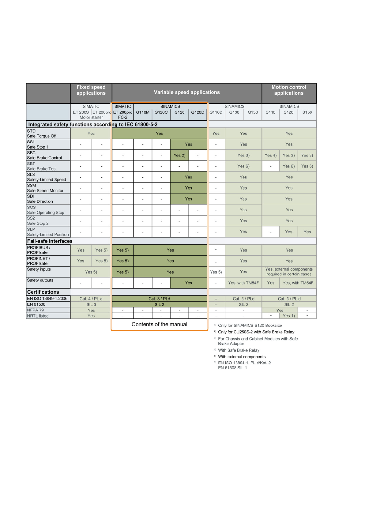
This manual describes the safety functions integrated in the inverter for variable-speed
applications.
The manual is aimed primarily at machine and plant manufacturers, commissioning
engineers, and service personnel.
"Safety" functions have, in comparison to "standard" drive functions, an especially low error
rate. Performance level (PL) and safety integrity level (SIL) of the corresponding standards
are a measure of the error rate.
As a consequence, the safety functions are suitable for use in safety-related applications to
minimize risk. An application is safety-related if the risk analysis of the machine or the
system indicates a special hazard potential in the application.
"Integrated in the drive" means that the safety functions are integrated in the inverter and
can be executed without requiring additional external components.
Safety Integrated - SINAMICS G110M, G120, G120C, G120D and SIMATIC ET 200pro FC-2
Function Manual, 04/2014, FW V4.7, A5E34261271B AA
15
Page 16
Introduction
What inverters are described?
2.1 About this manual
Figure 2-1 Products with drive-integrated safety functions
Safety Integrated - SINAMICS G110M, G120, G120C, G120D and SIMATIC ET 200pro FC-2
16 Function Manual, 04/2014, FW V4.7, A5E34261271B AA
Page 17

Introduction
What applications are described?
What other information do you need?
What is the meaning of the symbols in the manual?
An operating instruction starts here.
This concludes the operating instruction.
2.1 About this manual
This manual covers all the information, procedures, and operations for the following
scenarios:
● Introductory and simplified description of the inverter safety functions
● Controlling the safety functions via safety inputs or PROFIsafe
● Commissioning and acceptance test of the safety functions
● Response of the inverter with active safety functions
● Replacing an inverter where the safety functions are enabled.
● Diagnostics of the safety functions
The appendix contains an overview of the applicable regulations and standards for using the
safety functions.
This manual alone is not sufficient for installing or commissioning the standard inverter
functions. An overview of the documentation available and the associated applications is
provided in the sectionManuals for your inverter (Page 334).
Safety Integrated - SINAMICS G110M, G120, G120C, G120D and SIMATIC ET 200pro FC-2
Function Manual, 04/2014, FW V4.7, A5E34261271B AA
17
Page 18

Introduction
2.2
Guide through the manual
Chapter
In this chapter, you will find answers to the following questions:
2.2 Guide through the manual
Description (Page 19)
Installing (Page 41)
Commissioning (Page 77)
Operation (Page 159)
Corrective maintenance
(Page 251)
System properties
(Page 267)
Appendix (Page 277)
• What safety functions does my inverter have?
• How do the safety functions basically work?
• What are typical applications for the safety functions of the inverter?
• In which applications are the safety functions of my inverter not permitted?
• How many safety inputs and outputs does my inverter have?
• How do I wire up the safety inputs and outputs of my inverter?
• What do I have to observe if the wiring extends beyond the control cabinet?
• How are the PROFIsafe control words and status words assigned?
• How do I configure the communication of my inverter via PROFIsafe?
• How do I start commissioning the safety functions?
• What tool do I need for commissioning?
• How do I transfer the parameters of the safety functions to other inverters?
• How do I reset my inverter to the factory setting?
• How must I select and deselect the safety function?
• How do the inverter and motor respond when the safety function is active?
• How do the safety functions mutually influence one another?
• What happens in the event of a limit violation of the safety functions?
• What happens in the event of a wire breakage at a safety input?
• How do I acknowledge safety function faults?
• How do I replace defective components of the inverter or the inverter itself?
• How do I ensure that the safety functions are still working correctly after making a
replacement?
• What do I have to check after making a replacement?
• What is the meaning of the alarms and faults, which are assigned to the safety
functions?
• How long does it take for my drive to respond when selecting a safety function?
• How long does it take for my drive to respond when the safety function is active and the
motor malfunctions?
• What are the probabilities of failure of the safety functions of my inverter?
• According to which standards are the safety functions of my inverter certified?
• How do I check the safety functions after commissioning?
• How do I document the settings of the safety functions?
• As machine manufacturer or company operating a machine, what standards and
regulations must I observe?
• Where can I find more information on my inverter?
Safety Integrated - SINAMICS G110M, G120, G120C, G120D and SIMATIC ET 200pro FC-2
18 Function Manual, 04/2014, FW V4.7, A5E34261271B AA
Page 19

3
3.1
About this chapter
What can you find in this Chapter?
3.2
Overview of the safety functions
Basic functions and extended functions
Safety functions integrated in the drive
Basic functions
Extended functions
the extended functions.
This section provides an overview of the principle mode of operation of safety functions
integrated in the drive.
● Preconditions and restrictions when using the safety functions
● The principle mode of operation of safety functions integrated in the drive
● Application examples
● The assignment as to which inverters have which safety functions
The safety functions integrated in the drive are split up according to basic functions and
extended functions.
The basic functions prevent hazardous motion
using one or several of the following measures:
• The energy feed to the motor is safely
switched off
• The motor holding brake solenoid is safely
deenergized
The following basic functions are available:
• Safe Torque Off (STO)
• Safe Brake Control (SBC)
• Safe Stop 1 (SS1) without speed monitoring
Each of the inverters described in this manual
has one or several of the basic functions.
Extended functions include several basic
functions and additional functions to safely
monitor the motor speed:
• STO and SBC basic functions
• Safe Stop 1 (SS1) with speed monitoring
• Safely Limited Speed (SLS)
• Safe Direction (SDI)
• Safe Speed Monitor (SSM)
Whether an inverter has extended functions
generally depends on the Control Unit hardware.
The corresponding inverters have an "F" at the
end of the product name, e.g. Control Unit
CU240E-2 F. For SINAMICS G120 with a
CU250S-2 Control Unit, you require a license for
Safety Integrated - SINAMICS G110M, G120, G120C, G120D and SIMATIC ET 200pro FC-2
Function Manual, 04/2014, FW V4.7, A5E34261271B AA
19
Page 20
Description
Inverter
Basic functions
Extended functions
STO
SS1, SBC
SS1, SDI, SSM, SLS
SLS levels
SINAMICS G110M
SINAMICS G120C
CU250S-2 CAN
CU250D-2 PN-F FO
FC-2
2 Requires a license for the safety functions
3.2 Overview of the safety functions
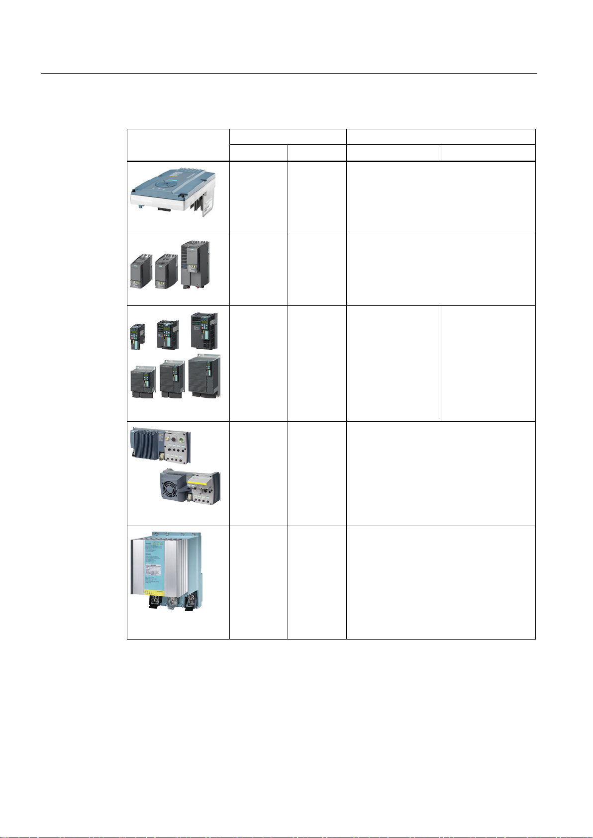
Table 3- 1 Inverters with safety functions integrated in the drive
SINAMICS G120
SINAMICS G120D
Available
with all
product
versions
Available
with all
product
versions
Available
with all
CU240E-2
and
CU250S-2
Control
Units
Available
with all
Control
Units
1)
---
---
--- ---
Available
with all
CU250S-2
Control
Units
Available with the
following Control
Units:
CU240E-2 F
CU240E-2 DP-F
CU240E-2 PN-F
2)
CU250S-2
CU250S-2 DP
CU250S-2 PN
2)
2)
2)
Available with the
following Control
Units:
CU240E-2 DP-F
CU240E-2 PN-F
CU250S-2 DP
CU250S-2 PN
--- Available with the following Control Units:
CU240D-2 DP-F
CU240D-2 PN-F
CU240D-2 PN-F PP
CU240D-2 PN-F FO
CU250D-2 DP-F
CU250D-2 PN-F
CU250D-2 PN-F PP
2)
2)
SIMATIC ET 200pro
1)
---: Not available
Safety Integrated - SINAMICS G110M, G120, G120C, G120D and SIMATIC ET 200pro FC-2
20 Function Manual, 04/2014, FW V4.7, A5E34261271B AA
Available --- ---
Page 21
Description
3.3
Overview of the safety-related inverter interfaces
Inverter
F-DI
F-DO
PROFIsafe
Safety output for a brake
SINAMICS G110M with Control Unit …
CU240M USS
1
---
---
---
CU240M PN
SINAMICS G120C CAN
SINAMICS G120 with Control Unit …
CU240E-2
1
---
---
---
CU240E-2 PN
CU240E-2 F
3
---
---
---
CU240E-2 PN-F
Telegram 900
CU250S-2 CAN
Relay
CU250S-2 PN
Telegram 900
Relay
SINAMICS G120D with Control Unit …
CU240D-2 PN
CU250D-2 PN-F FO
Telegram 900: Function as for telegram 30 and additional feedback signal of the F-DI status
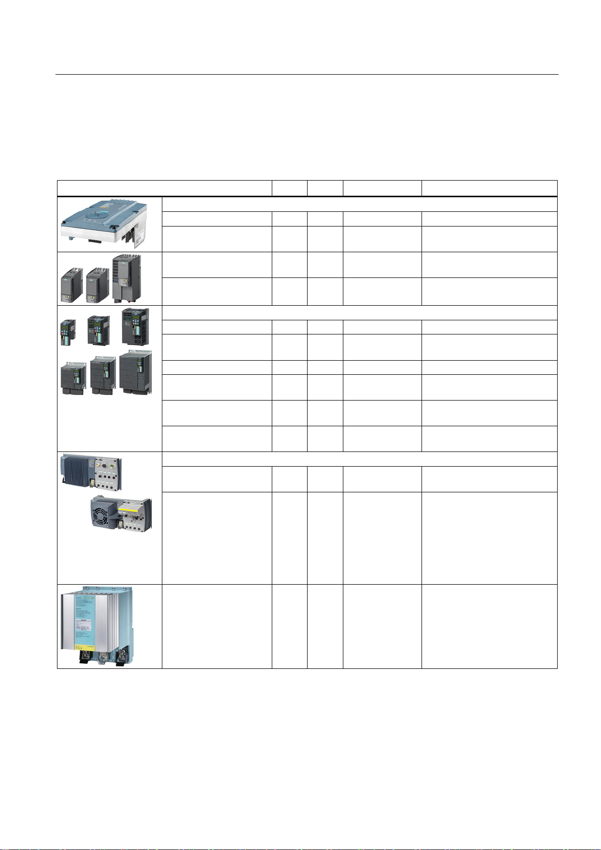
3.3 Overview of the safety-related inverter interfaces
Depending on the particular inverter, the interfaces of the safety functions are safety inputs
and outputs (F-DI, F-DO), the safety-related PROFIsafe fieldbus communication and a safety
output to control a brake.
1)
CU240M DP
1 --- Telegram 30
3)
---
SINAMICS G120C USS
SINAMICS G120C DP
SINAMICS G120C PN
CU240E-2 DP
CU240E-2 DP-F
CU250S-2
CU250S-2 DP
CU240D-2 DP
CU240D-2 DP-F
CU240D-2 PN-F
CU240D-2 PN-F PP
CU240D-2 PN-F FO
CU250D-2 DP-F
CU250D-2 PN-F
CU250D-2 PN-F PP
1 --- --- ---
1 --- Telegram 30
1 --- Telegram 30
3 --- Telegram 30
3)
---
3)
---
3)
,
4)
---
3 1 --- Available with Safe Brake
3 1 Telegram 30
1 --- Telegram 30
3 1 Telegram 30
Telegram 900
3)
,
4)
3)
3)
4)
Available with Safe Brake
---
,
---
SIMATIC ET 200pro
FC-2
1)
--- Not available
2)
The inverter evaluates the F0 rail in the backplane bus of the ET 200pro system using an internal safety input. The
ET 20
0pro
--- ET 200pro
2)
ET-200pro F-RSM and F-Switch modules control the F0 rail.
3)
Telegram 30 for control and for the status feedback signal from the safety functions
4)
Safety Integrated - SINAMICS G110M, G120, G120C, G120D and SIMATIC ET 200pro FC-2
Function Manual, 04/2014, FW V4.7, A5E34261271B AA
2)
---
21
Page 22

Description
3.4
Preconditions when using the safety functions
Risk assessment
Motors and control modes
Encoderless safety functions
Taking into account the slip of induction motors
3.4 Preconditions when using the safety functions
A risk analysis and assessment of the plant or machine is required before using the safety
functions integrated in the drive.
The risk analysis and assessment must show that the safety functions integrated in the drive
are suitable as protective measure to reduce risks associated with the machine. The
required probability of failure of the protective measure must not exceed SIL 2 or PL d.
You can use the basic functions without any restrictions:
● For all control modes: U/f control and speed control with and without encoder
● With synchronous and induction motors
● For group drives, which involves the simultaneous operation of several motors connected
to one inverter
It is only permissible that you use the extended functions under the following preconditions:
● With induction motors for all control modes
● With SIEMOSYN synchronous motors only with U/f control
● For group drives
The safety functions integrated in the drive do not use an encoder.
"Encoderless" means the following:
● You do not require an encoder to use the safety functions integrated in the drive.
● If the inverter has an encoder connection, the inverter uses the encoder signal to control
(closed loop) the motor. The safety functions ignore the encoder signal.
The speed of the motor shaft is relevant for the functional safety in or on a machine.
However, the extended functions monitor the electrical speed of the motor against the limit
values that have been set.
If you use encoderless safety functions with an induction motor, you must take into account
the motor slip when setting the speed monitoring.
Safety Integrated - SINAMICS G110M, G120, G120C, G120D and SIMATIC ET 200pro FC-2
22 Function Manual, 04/2014, FW V4.7, A5E34261271B AA
Page 23
Description
3.5
Restrictions when using safety functions
Not permitted: Operation with pulling loads
WARNING
Death or severe injury when the motor speed is not monitored
Speed monitoring options for pulling loads
Not permitted: Motors with different pole pair numbers
WARNING
Death or serious injury due to unexpected high speeds
Monitoring the speed of motors with different pole pair numbers
3.5 Restrictions when using safety functions
The encoderless actual value sensing does not identify all faults and errors in the closedloop motor control. As a consequence, the encoderless safety functions cannot identify
whether a pulling load unintentionally accelerates due to a fault or error in the closed-loop
motor control.
• Do not use any of the extended encoderless safety functions in a drive with a pulling
load.
It is not permissible that you use the encoderless safety functions in applications involving
pulling loads, e.g. in hoisting gear, elevators and unwinders.
● You can implement speed monitoring in machines with pulling loads in one the following
ways:
– Select a drive with safety functions that use an encoder, for example SINAMICS S120.
– Implement the speed monitoring in the higher-level control by using a suitable
measuring system to acquire the speed/velocity.
● Coupled electric drives, e.g. test stands and winders/unwinders comprise a driving and a
driven drive. Using the extended functions in the drive that has a driving function in a
coupled drive system. In the case of a fault, the drive with the driving function identifies
when a limit value is violated.
If you use the "Drive data set" function to switch over motors with different pole pair
numbers, then the calculated, safety-related speed differs from the mechanical speed of the
motor shaft. As a consequence, the motor shaft can accelerate above the configured
monitoring limits of the safety function. This can result in death or severe injury.
• When using the "drive data set" function, only switch between motors with the same
pole pair number.
Implement the speed monitoring in the higher-level control by using a suitable measuring
system to acquire the velocity or speed.
Safety Integrated - SINAMICS G110M, G120, G120C, G120D and SIMATIC ET 200pro FC-2
Function Manual, 04/2014, FW V4.7, A5E34261271B AA
23
Page 24

Description
Critical applications
Critical application
Remedy
commissioning
identification has been completed.
Setpoint change as step function
long.
Load change as step function
5 % of the rated speed
Operating an inverter at the current
does not reach its current or torque limits – even at full load.
using a control signal.
3.5 Restrictions when using safety functions
For safety functions that have not been enabled, you can use the following applications
without any restrictions.
For active safety functions, several applications can result in errors in the safety-related
actual value sensing. For active or enabled safety functions, faults and errors in the safetyrelated actual value sensing initiate a stop response: Messages C01711, C30711 with
default values 1040 ff.
The stop response does not result in an unsafe drive state, but in a lower drive availability.
Motor data identification during
Reversing the speed
Continuous operation at speeds <
Switching-on the inverter with the
motor rotating ("flying restart"
function)
limit
Braking a motor using the "DC
braking" or "Compound braking"
functions
Only commission the safety functions after the motor data
Set the ramp-function generator times to values > 0.5 s.
If you are using an inverter with position control, then you must
set the position controller and the travel profile so that there is
absolutely no overshoot in the speed/velocity characteristic.
Within 1 s, only one acceleration and one braking ramp are
→ -n
permitted. The cycle 0 → n
Do not use the safety functions.
Avoid using the "flying restart" function when a safety function is
active.
Temporarily deactivate the safety function until the "flying
restart" function has been successfully completed.
It is not permissible that you use the "flying restart" function if
you are using the SSM function. It is not possible to deactivate
SSM using a control signal.
Select and dimension the drive so that the inverter current limit
does not respond. After commissioning, check that the inverter
Avoid using the "DC braking" or "Compound braking" functions
when a safety function is active.
If you require one of these two braking functions, then in the risk
assessment, you must carefully check as to whether you may
deactivate the safety function while braking. If yes, then
deactivate the safety function until braking has been completed.
It is not permissible that you use the braking functions if you are
using the SSM function. It is not possible to deactivate SSM
set
→ 0 must be at least 2 s
set
Safety Integrated - SINAMICS G110M, G120, G120C, G120D and SIMATIC ET 200pro FC-2
24 Function Manual, 04/2014, FW V4.7, A5E34261271B AA
Page 25

Description
Inadmissible SINAMICS G120 Power Modules
Power Module
Restriction
safety functions.
basic functions without speed monitoring are permitted.
3.5 Restrictions when using safety functions
When using the following Power Modules, it is not it permissible to use the safety functions
nor are you able to:
PM230 The PM230 Power Modules of the SINAMICS G120 do not support any
PM240 FSGX With the PM240 Power Module frame size GX, only the STO, SBC and SS1
Safety Integrated - SINAMICS G110M, G120, G120C, G120D and SIMATIC ET 200pro FC-2
Function Manual, 04/2014, FW V4.7, A5E34261271B AA
25
Page 26

Description
3.6
Recommendations for stable operation
3.6 Recommendations for stable operation
The following preconditions must be satisfied to ensure disturbance-free inverter operation
with the extended functions enabled:
● Motor and inverter are adequately dimensioned for this application:
– The inverter is operated below its current limit.
– The rated currents of the motor and inverter must not differ by more than a factor of 5:
Inverter rated current/motor rated current < 5 (r0207[0] / p0305 < 5).
● Before commissioning the safety functions, optimally set the closed-loop control:
– Carry out motor data identification at standstill.
– Carry out a rotating measurement.
– Avoid multiple speed overshoots when settling after a setpoint change.
– Avoid reversing the motor within less than 2 s.
Safety Integrated - SINAMICS G110M, G120, G120C, G120D and SIMATIC ET 200pro FC-2
26 Function Manual, 04/2014, FW V4.7, A5E34261271B AA
Page 27
Description
3.7
Safe Torque Off (STO)
How does the STO safety function work?
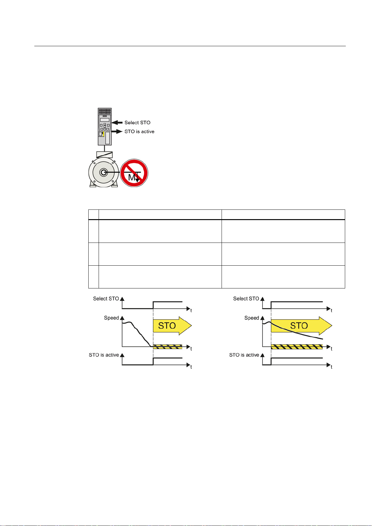
The inverter with active STO function prevents machine
components from inadvertently starting.
Safe Torque Off (STO)
Standard inverter functions linked with STO
safe communication.
not generate any torque.
safe communication.
The STO safety function is standardized
3.7 Safe Torque Off (STO)
Table 3- 2 The principle of operation of STO
1. The inverter recognizes the selection of STO
via a safety-relevant input or via the PROFIsafe
2. The inverter prevents energy from being fed to
the motor. When STO is active, the motor does
3. The inverter signals that "STO is active" via a
safety-relevant output or via the PROFIsafe
---
If you use a motor holding brake, the inverter
closes the brake.
---
Figure 3-1 Functionality of STO when motor is rotating and at a standstill
If the motor is still rotating when STO is selected, then it coasts down to standstill.
The STO function is defined in IEC/EN 61800-5-2:
"[…] [The inverter] does not supply any energy to the motor which can generate a torque (or
for a linear motor, a force)."
Safety Integrated - SINAMICS G110M, G120, G120C, G120D and SIMATIC ET 200pro FC-2
Function Manual, 04/2014, FW V4.7, A5E34261271B AA
The STO inverter function complies with what is defined in the standard.
27
Page 28
Description
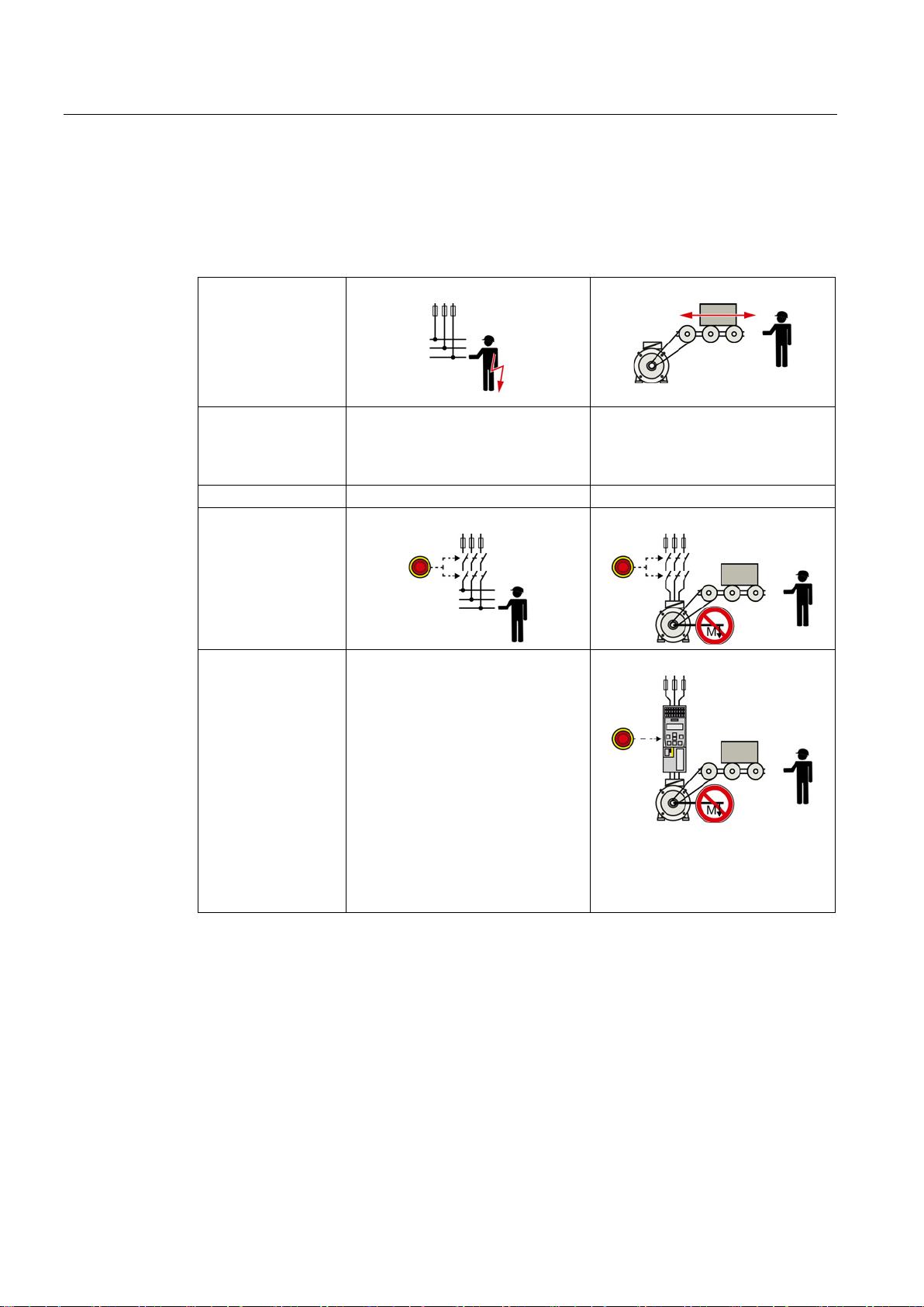
The distinction between Emergency Off and Emergency Stop
Safe switch off
completely or partially.
Safely stop and safely prevent
restarting
Stopping or preventing the dangerous
movement
Command:
Emergency Off
Emergency Stop
measurement.
3.7 Safe Torque Off (STO)
"Emergency Off" and "Emergency Stop" are commands that minimize different risks in the
machine or plant.
The STO function is suitable for achieving an emergency stop but not an emergency off.
Risk: Risk of electric shock:
Measure to minimize
risk:
Switching off the electric power
supply for the installation, either
Risk of unexpected motion:
Classic solution: Switch of the power supply:
Solution with the STO
safety function
integrated in the
drive:
STO is not suitable for safely
switching of an electric voltage.
Switch-of the drive power supply:
Select STO:
It is permissible that you switch of the
inverter supply voltage as well.
However, switching off the voltage is
not required as a risk-reduction
Safety Integrated - SINAMICS G110M, G120, G120C, G120D and SIMATIC ET 200pro FC-2
28 Function Manual, 04/2014, FW V4.7, A5E34261271B AA
Page 29

Description
Application examples for the STO function
Examples
Possible solution
3.7 Safe Torque Off (STO)
The STO function is suitable for applications where the motor is already at a standstill or will
come to a standstill in a short, safe period of time through friction. STO does not shorten the
run-on of machine components with high inertia.
When the Emergency Stop button is pressed, a
stationary motor should not unintentionally start.
A central emergency stop button must prevent the
unintentional acceleration of several motors that
are at a standstill.
• Wire the Emergency Stop button to a
safety-related input of the inverter.
• Select STO via the safety-related input.
• Evaluate the Emergency Stop button in a
central control.
• Select STO via PROFIsafe.
Safety Integrated - SINAMICS G110M, G120, G120C, G120D and SIMATIC ET 200pro FC-2
Function Manual, 04/2014, FW V4.7, A5E34261271B AA
29
Page 30
Description
3.8
Safe Brake Control (SBC)
How does the SBC safety function work?
Safe Brake Control (SBC)
Standard brake functions
inverter requests the SBC function via
The Safe Brake Relay safely switches
connected brake.
3.8 Safe Brake Control (SBC)
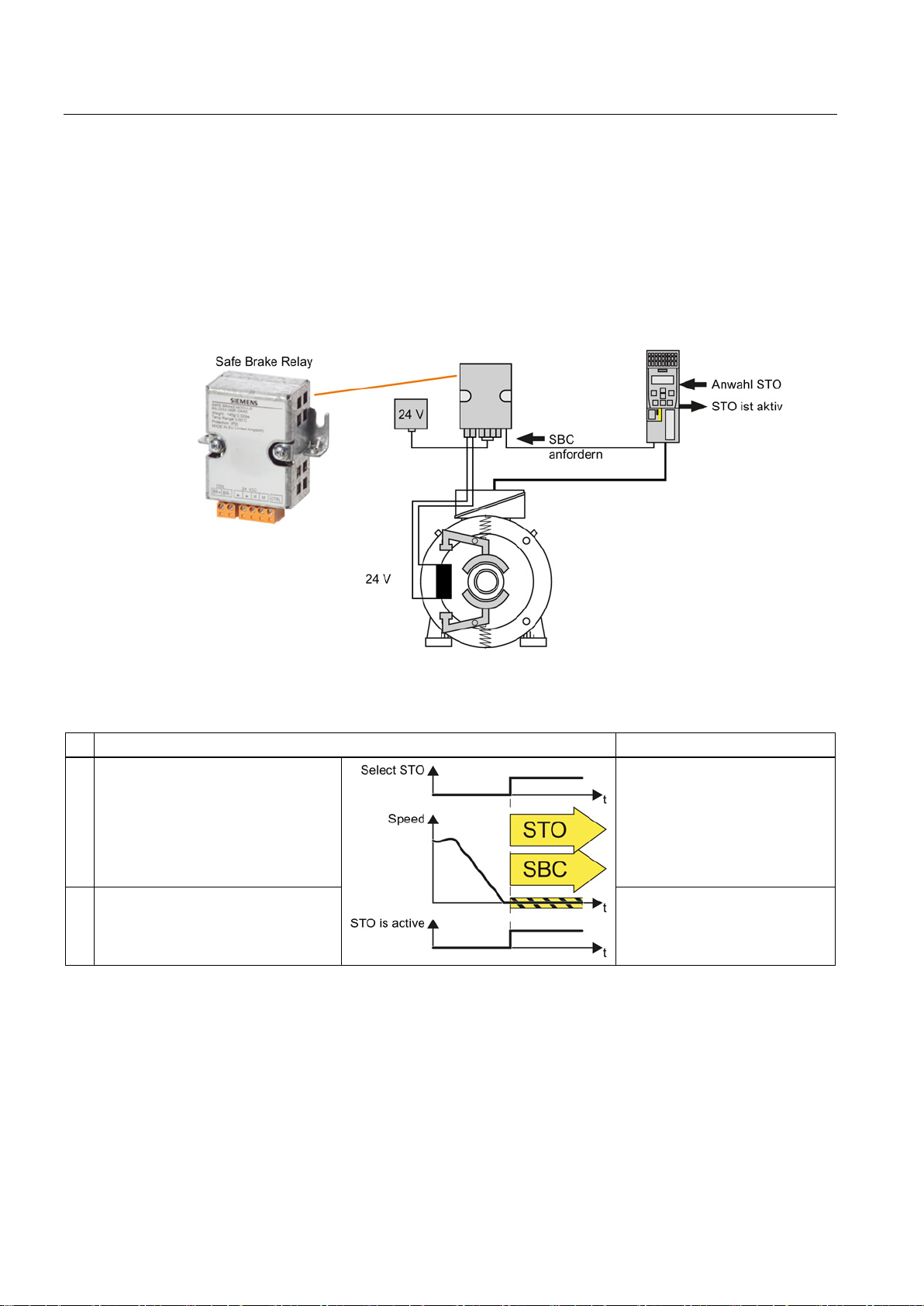
An inverter equipped with the SBC function monitors the cables to an electromagnetic brake
and when requested, safely shuts down the 24 V control of the brake.
You must supplement the inverter with a Safe Brake Relay for the SBC function.
The brake can be integrated in the motor or externally mounted.
Table 3- 3 The principle of operation of SBC
1. When the STO function is active, the
the connecting cable to the Safe
Brake Relay.
off the supply voltage for the
2. The inverter signals that "STO is
active" via a safety output or via the
PROFIsafe safe communication.
The safety-related brake control does not mean that the brake keeps the load in position.
The SBC function is not able to identify as to whether the brake is mechanically worn, for
example.
The brake closes.
The brake maintains the motor
shaft in position.
---
Safety Integrated - SINAMICS G110M, G120, G120C, G120D and SIMATIC ET 200pro FC-2
30 Function Manual, 04/2014, FW V4.7, A5E34261271B AA
Page 31

Description
The SBC safety function is standardized
Application example for the SBC function
Example
Possible solution
3.8 Safe Brake Control (SBC)
The SBC function is defined in IEC/EN 61800-5-2:
"The SBC function supplies a safe output signal to control an external brake."
The SBC inverter function complies with what is defined in the standard.
After a hoisting gear stops, the inverter must close
the brake in order to minimize the risk of the load
falling.
• Connect the motor holding brake to the
inverter via Safe Brake Relay.
• Select STO when the drive stops.
Safety Integrated - SINAMICS G110M, G120, G120C, G120D and SIMATIC ET 200pro FC-2
Function Manual, 04/2014, FW V4.7, A5E34261271B AA
31
Page 32
Description
3.9
Safe Stop 1 (SS1)
How does SS1 function?
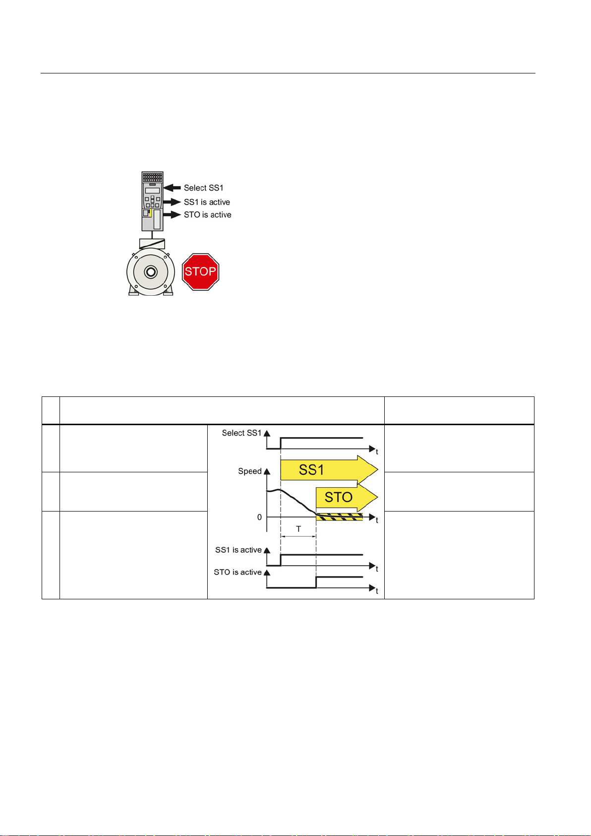
When the SS1 function is active, the inverter reduces the
kinetic energy of the machine components to the lowest
possible level.
SS1 of the basic functions
Safe Stop 1 (SS1)
Standard inverter functions linked
with SS1
communication.
active".
safely switches off the motor torque
3.9 Safe Stop 1 (SS1)
The principle of operation of SS1 differs depending on whether you use SS1 with basic
functions or with extended functions.
Table 3- 4 Principle of operation of SS1, selected when the motor is rotating
1. The inverter recognizes the
selection of SS1 via a safety input
or via the PROFIsafe safe
---
2. SS1 starts a safety timer T.
The inverter signals "SS1 is
3. After the timer expires, the inverter
with the STO function.
The inverter signals that "STO is
active" via a safety output or via the
PROFIsafe safe communication.
Safety Integrated - SINAMICS G110M, G120, G120C, G120D and SIMATIC ET 200pro FC-2
32 Function Manual, 04/2014, FW V4.7, A5E34261271B AA
The inverter brakes the motor along
the OFF3 ramp.
---
Page 33
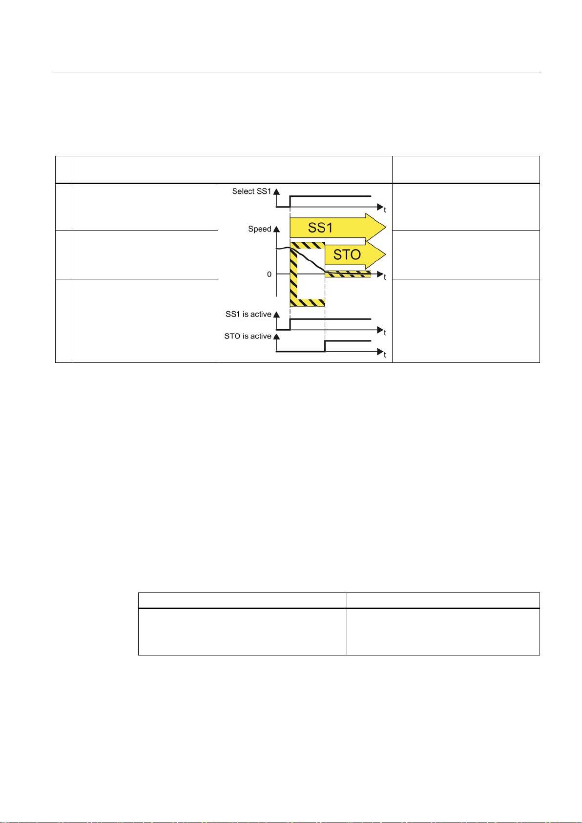
Description
SS1 of the extended functions
Safe Stop 1 (SS1)
Standard inverter functions linked
with SS1
communication.
The inverter monitors as to whether
active".
active" via a safety output or via the
The SS1 safety function is standardized
Application example
Example
Possible solution
undesirably restarts.
3.9 Safe Stop 1 (SS1)
Table 3- 5 Principle of operation of SS1, selected when the motor is rotating
1. The inverter recognizes the
selection of SS1 via a safety input
or via the PROFIsafe safe
2.
the motor speed decreases.
The inverter signals "SS1 is
3. If the motor speed is low enough,
the inverter safely switches off the
motor torque using STO.
The inverter signals that "STO is
PROFIsafe safe communication.
The SS1 function is defined in IEC/EN 61800-5-2:
"[…] [1] Initiate and monitor the magnitude of the motor deceleration within the defined limits
and initiate the STO function if the motor speed falls below a defined limit value.
or
[2] Initiate motor deceleration and activate the STO function after an application-specific time
delay."
---
The inverter brakes the motor along
the OFF3 ramp.
---
Safety Integrated - SINAMICS G110M, G120, G120C, G120D and SIMATIC ET 200pro FC-2
Function Manual, 04/2014, FW V4.7, A5E34261271B AA
The inverter function SS1 of the extended functions complies with the first definition of the
standard.
The inverter function SS1 of the basic functions complies with the second definition of the
standard.
The drive must brake as quickly as possible after
the Emergency Stop button has been pressed. It is
not permissible that the stationary motor
• Select SS1 in the inverter using a safety
input or via PROFIsafe.
33
Page 34
Description
3.10
Safely Limited Speed (SLS)
How does SLS function?
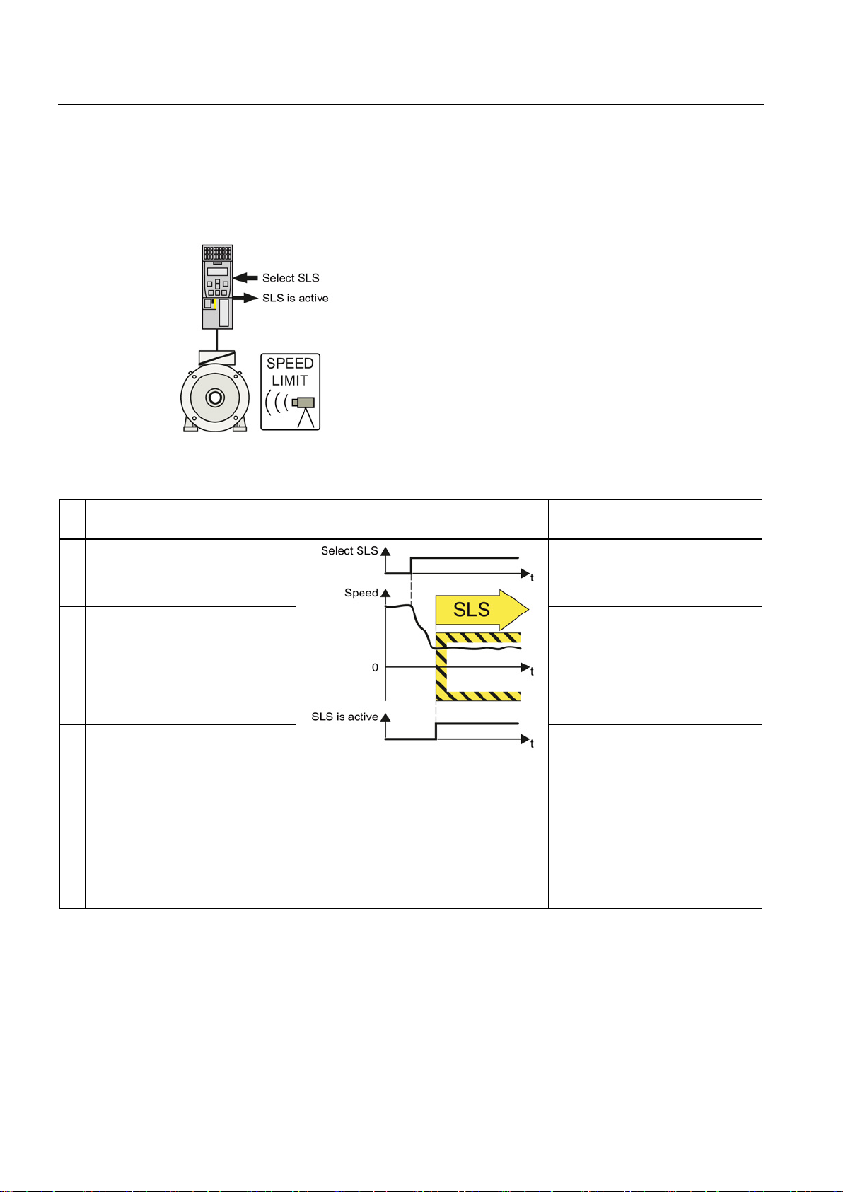
An inverter with active SLS function can reduce the
velocity or speed of a machine component and monitor
it without having to inter
Safely Limited Speed (SLS)
Standard inverter functions linked
with SLS
communication.
active" via a safety output or via the
possible.
The SLS safety function is standardized
3.10 Safely Limited Speed (SLS)
Table 3- 6 Principle of operation of SLS, selected when the motor is rotating
1. The inverter recognizes the
selection of SLS via a safety input
or via the PROFIsafe safe
2. SLS allows a motor to reduce its
possibly inadmissibly high speed
within a defined time – or to reduce
it along a defined braking ramp.
3. The inverter monitors the absolute
actual speed against the set SLS
monitoring.
The inverter signals that "SLS is
rupt machining operation.
---
The inverter limits the speed
setpoint to values below the SLS
monitoring.
If the motor rotates faster than the
SLS monitoring value, then the
inverter brakes the motor along the
OFF3 ramp.
The inverter limits the speed
setpoint to values below the SLS
monitoring.
PROFIsafe safe communication.
If the motor speed exceeds the
SLS monitoring, the inverter
responds with a "safe stop" and
brakes the motor as quickly as
The SLS function is defined in IEC/EN 61800-5-2:
Safety Integrated - SINAMICS G110M, G120, G120C, G120D and SIMATIC ET 200pro FC-2
34 Function Manual, 04/2014, FW V4.7, A5E34261271B AA
"The SLS function prevents the motor from exceeding the defined speed limit."
The SLS inverter function complies with what is defined in the standard.
Page 35
Description
Application examples for the SLS function
Examples
Possible solution
introduce material into a machine part.
from damage.
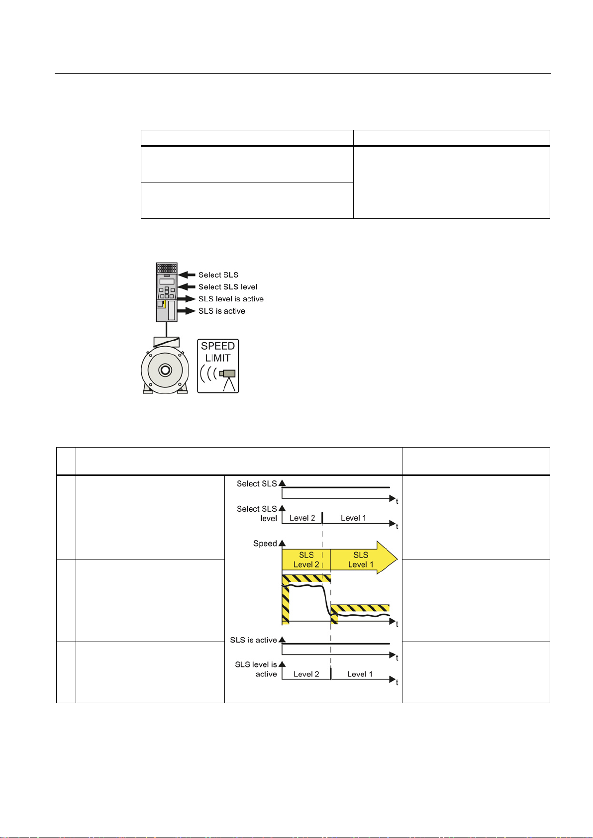
Functional expansion: selecting SLS levels
Expansion of the SLS function to include several SLS
levels:
•
•
Safely Limited Speed (SLS)
Standard inverter functions linked
with SLS
PROFIsafe communication.
2.
OFF3 ramp.
PROFIsafe communication.
3.10 Safely Limited Speed (SLS)
Setup mode: The machine operator must enter the
dangerous area of a machine and manually
A turning machine must not exceed a specific
maximum torque in order to protect the drill chuck
• Select SSL in the inverter via a safety input
or via PROFIsafe.
• The inverter limits and monitors the speed
of the machine part.
The speed monitoring of the SLS function can be
extended to include a maximum of 4 different SLS
levels.
The inverter requires additional safety-related
signals to select an SLS level and to signal back
which SLS level is active.
The switchover from a higher SLS level 2 to a lower SLS level 1 is described as example.
Table 3- 7 Switching over from SLS level 2 to SLS level 1
1. The inverter signals "SLS level 2 is
active" via the safety-related
2. The inverter recognizes the
selection of SLS level 1 via the
safety-related PROFIsafe
communication.
3. SLS allows a motor to reduce its
possibly inadmissibly high speed
within a defined time – or to reduce
it along a defined braking ramp.
4. The inverter monitors the absolute
actual speed against SLS level 1.
The inverter signals "SLS level 1 is
active" via the safety-related
The inverter limits the speed
setpoint to values below SLS level
The inverter limits the speed
setpoint to values below SLS level
1.
If the motor rotates faster than the
SLS monitoring value, then the
inverter brakes the motor along the
The inverter limits the speed
setpoint to values below SLS level
1.
Safety Integrated - SINAMICS G110M, G120, G120C, G120D and SIMATIC ET 200pro FC-2
Function Manual, 04/2014, FW V4.7, A5E34261271B AA
35
Page 36

Description
Application example for selecting SLS levels
Examples
Possible solution
speed.
3.10 Safely Limited Speed (SLS)
Depending on the diameter of the saw blade, a
circular saw must not exceed a specific maximum
• Select SLS and the corresponding SLS
level in the inverter via PROFIsafe.
Safety Integrated - SINAMICS G110M, G120, G120C, G120D and SIMATIC ET 200pro FC-2
36 Function Manual, 04/2014, FW V4.7, A5E34261271B AA
Page 37
Description
3.11
Safe Direction (SDI)
How does SDI function?
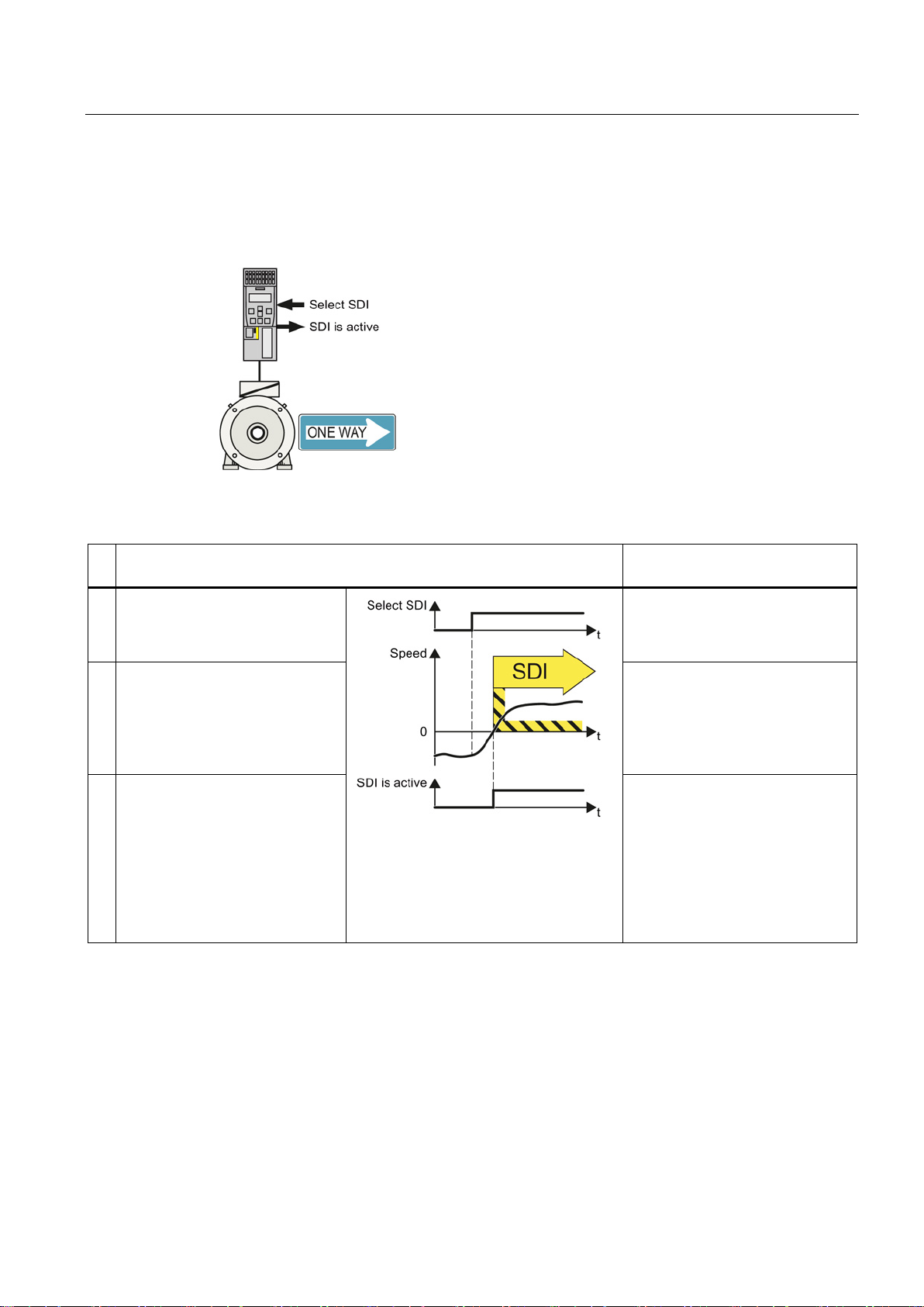
The inverter with active SDI function pre
machine component moves in the inhibited direction.
Safe Direction (SDI)
Standard inverter functions linked
with SDI
communication.
the motor along the OFF3 ramp.
active" via a safety output or via the
motor as quickly as possible.
The SDI safety function is standardized
3.11 Safe Direction (SDI)
Table 3- 8 Principle of operation of SDI, selected when the motor is rotating
1. The inverter recognizes the
selection of SDI via a safety input
or via the PROFIsafe safe
2. SDI allows a motor to stop moving
in the inhibited direction of rotation
within a defined time – or along a
defined braking ramp.
vents that a
---
The inverter limits the speed
setpoint to values in the selected
direction of rotation.
If the motor rotates in the inhibited
direction, then the inverter brakes
3. The inverter monitors the direction
of the actual speed.
The inverter signals that "SDI is
PROFIsafe safe communication.
If the motor rotates in the inhibited
direction, the inverter responds
with a "safe stop" and brakes the
The SDI function is defined in IEC/EN 61800-5-2:
"The SDI function prevents the motor shaft moving in the wrong direction."
The SDI inverter function complies with what is defined in the standard.
Safety Integrated - SINAMICS G110M, G120, G120C, G120D and SIMATIC ET 200pro FC-2
Function Manual, 04/2014, FW V4.7, A5E34261271B AA
The inverter limits the speed
setpoint to values in the selected
direction of rotation.
37
Page 38

Description
Application examples
Example
Possible solution
the safe direction.
the opening direction.
then it may only start in the opposite direction.
the roller must only turn in a specific direction.
3.11 Safe Direction (SDI)
When replacing the pressure cylinders of the
plates, it is only permissible that the drive moves in
After a protective device to detect a jammed door
responds, a rolling shutter gate may only move in
When a crane trolley is at the operating limit switch
To manually clean the roller in a printing machine,
• Select SDI in the inverter via a safety input
or via PROFIsafe.
• In the inverter, inhibit the direction of
rotation that is not permitted.
Safety Integrated - SINAMICS G110M, G120, G120C, G120D and SIMATIC ET 200pro FC-2
38 Function Manual, 04/2014, FW V4.7, A5E34261271B AA
Page 39
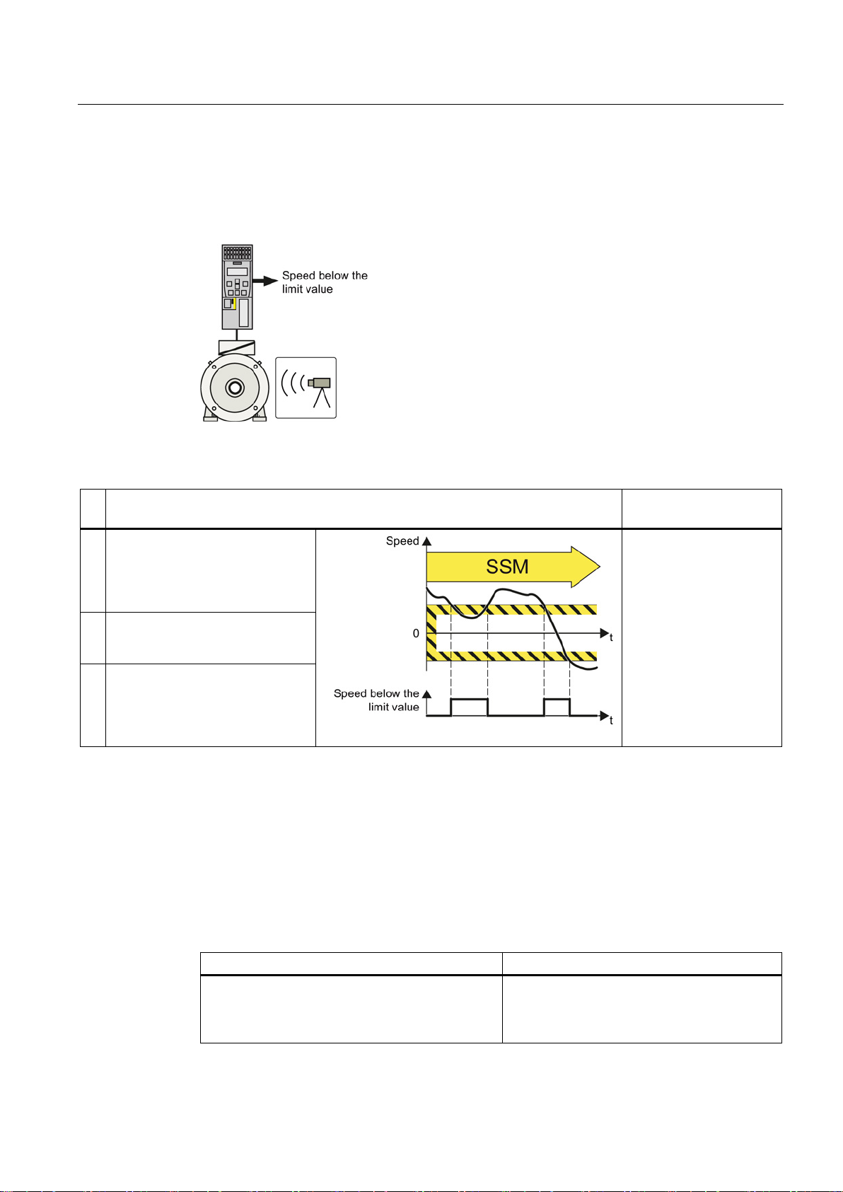
Description
3.12
Safe Speed Monitoring (SSM)
How does SSM function?
The inverter with active SSM function signals
whether the velocity or speed of a machine
component is above or below a limit value.
Safe Speed Monitoring (SSM)
Standard inverter
functions linked with SSM
active.
value.
PROFIsafe communication.
The SSM safety function is standardized
Application example
Example
Possible solution
limit value" via PROFIbus.
3.12 Safe Speed Monitoring (SSM)
Table 3- 9 The principle of operation of SSM
1. The SSM function cannot be
selected or deselected using
external control signals, in the
appropriate setting, it is always
2. The inverter compares the motor
speed with an adjustable limit
---
3. If the speed is less than the limit
value, the inverter signals "Speed
below limit value" via a safety
output or via safety-related
The SSM function is defined in IEC/EN 61800-5-2:
"The SSM function supplies a safe output signal to indicate whether the motor speed is
below a specified limit value."
The SSM inverter function complies with what is defined in the standard.
A centrifuge may only filled below a certain
minimum velocity.
The inverter safely monitors the centrifuge
speed and enables the process to advance to
the next step using the status bit "Speed below
Safety Integrated - SINAMICS G110M, G120, G120C, G120D and SIMATIC ET 200pro FC-2
Function Manual, 04/2014, FW V4.7, A5E34261271B AA
39
Page 40

Description
3.12 Safe Speed Monitoring (SSM)
Safety Integrated - SINAMICS G110M, G120, G120C, G120D and SIMATIC ET 200pro FC-2
40 Function Manual, 04/2014, FW V4.7, A5E34261271B AA
Page 41
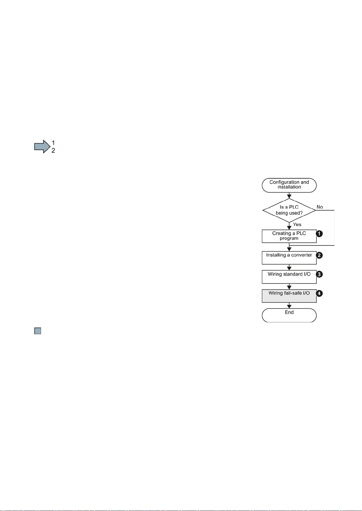
4
4.1
Installing the inverter
Procedure
1.
2.
3.
4.
The following overview shows the procedure for installing integrated safety functions in an
inverter. The step selected in gray is described in this manual. For information on the steps
that are not selected, you will need to consult descriptions in other manuals.
Proceed as follows:
If you are using a higher-level control system (PLC), then
create the control program first.
Install the inverter.
→ operating instructions of your inverter.
Connect the inverter to the line supply, and wire the
standard inputs and outputs of the inverter.
→ operating instructions of your inverter.
Connect the safety inputs and outputs
→ in this manual: Activation via F-DI (Page 51).
→ in this manual: Evaluating via F-DO (Page 71).
You have installed the inverter and prepared it for commissioning.
Safety Integrated - SINAMICS G110M, G120, G120C, G120D and SIMATIC ET 200pro FC-2
Function Manual, 04/2014, FW V4.7, A5E34261271B AA
41
Page 42
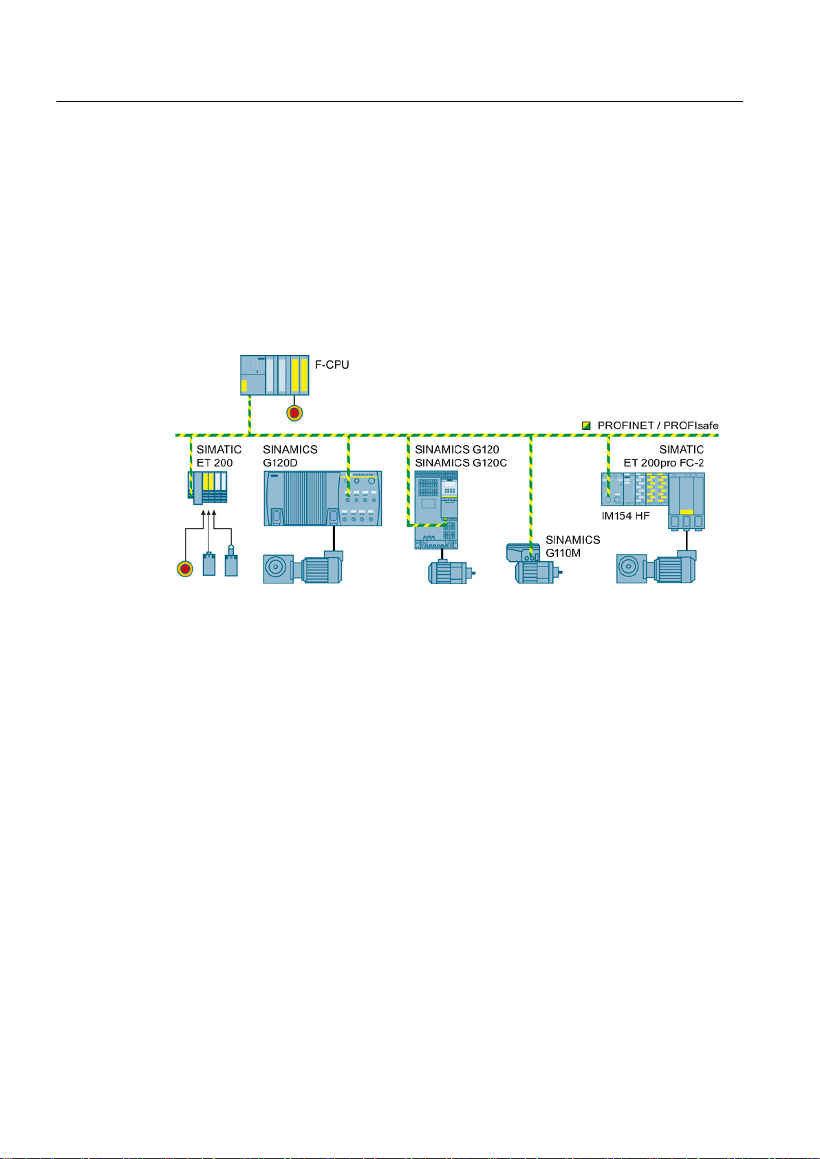
Installing
4.2
Connection via PROFIsafe
4.2.1
Overview of PROFIsafe connections
Communication via PROFIsafe
4.2 Connection via PROFIsafe
For communication via PROFIsafe, you must connect the inverter to a central fail-safe
control (F-CPU) via either PROFIBUS or PROFINET.
Figure 4-1 PROFIsafe communication between an F-CPU and an inverter, e.g. via PROFINET
Safety Integrated - SINAMICS G110M, G120, G120C, G120D and SIMATIC ET 200pro FC-2
42 Function Manual, 04/2014, FW V4.7, A5E34261271B AA
Page 43
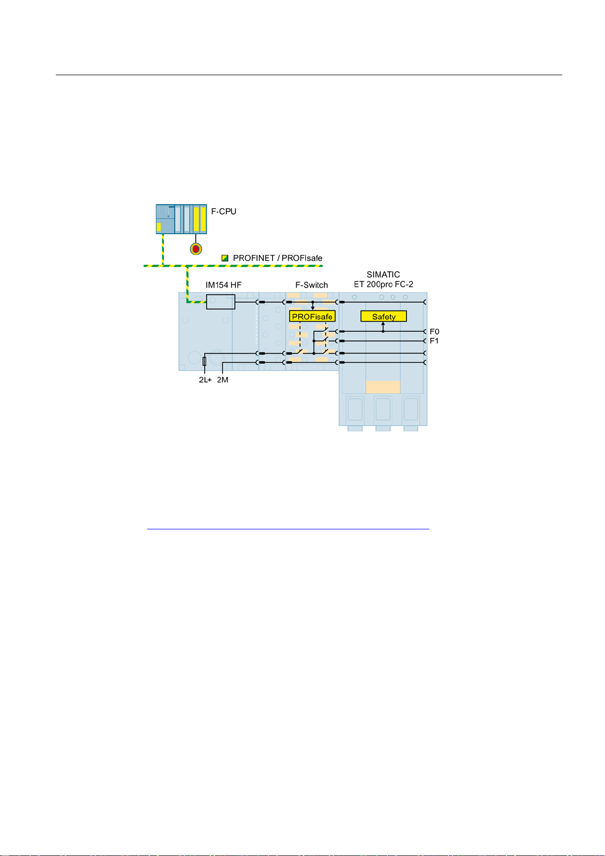
Installing
4.2 Connection via PROFIsafe
The SIMATIC ET 200pro FC-2 converter does not have its own PROFIsafe interface. The
central F-CPU controls the safety functions of the ET 200pro FC-2 via a "High Feature"
interface module and the PROFIsafe "F-Switch" module.
The F-Switch module switches the "F0" and "F1 rails" in the backplane bus of the ET-200pro
system. The inverter evaluates the F0 rail using an internal, safety input.
Figure 4-2 F-Switch to connect PROFIsafe of the ET 200pro FC-2 converter, e.g. via PROFINET
Additional information on the ET 200pro system and the F-Switch module is available in the
"SIMATIC distributed ET 200pro I/O system" Operating instructions. See also Section:
Manuals for your inverter (Page 334).
Additional possibilities of installing the F-Switch module are listed in the Internet: FAQ
(http://support.automation.siemens.com/WW/view/en/26694409).
Safety Integrated - SINAMICS G110M, G120, G120C, G120D and SIMATIC ET 200pro FC-2
Function Manual, 04/2014, FW V4.7, A5E34261271B AA
43
Page 44
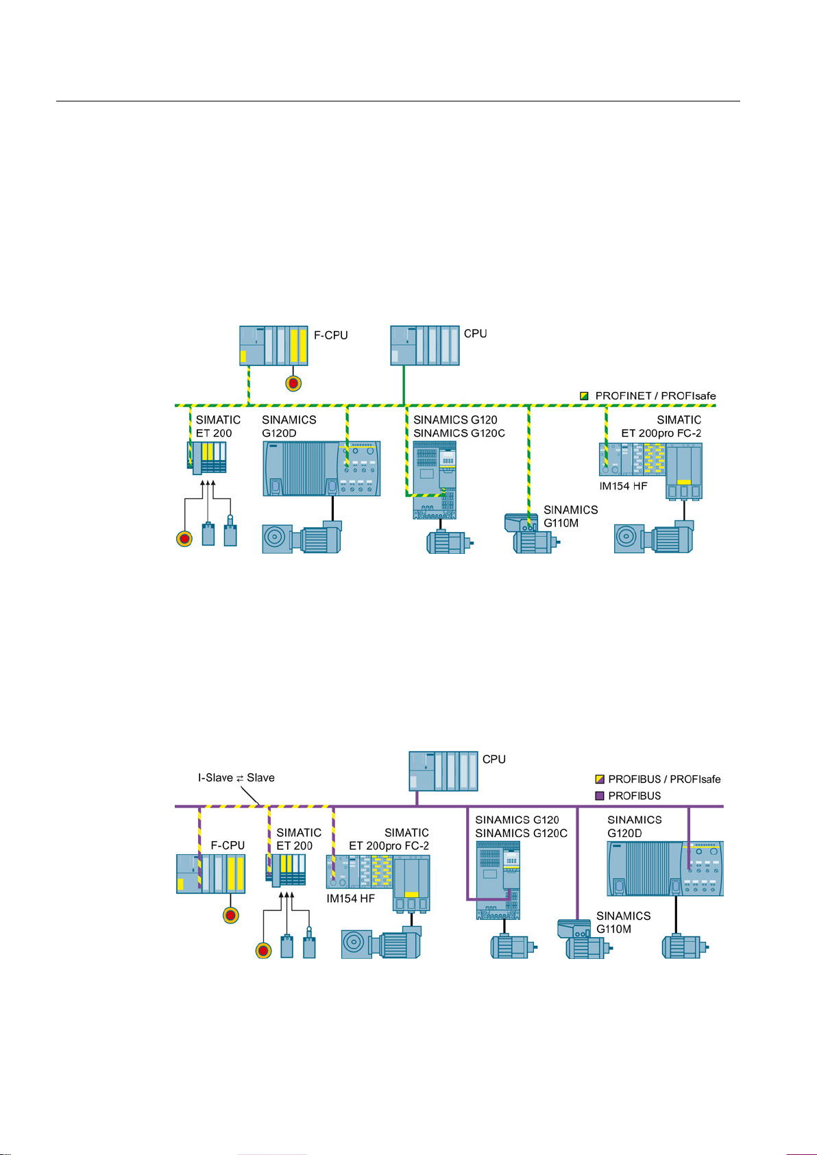
Installing
Shared Device
Communication I-slave ↔ slave
4.2 Connection via PROFIsafe
The PROFINET "Shared Device" function allows two controls to access the same
PROFINET IO device, e.g. on a SIMATIC ET 200 I/O system or on an inverter. Typical
applications for "Shared Device" are systems, in which a standard CPU and a fail-safe CPU
are used as separate controllers:
● The fail-safe controller (F-CPU) is responsible for the safety functions in the inverter or in
the SIMATIC ET 200 I/O system.
● The standard controller transfers all other signals.
Figure 4-3 Shared device is possible with every inverter
It is only possible to use an F-CPU as I slave via PROFIBUS.
The SIMATIC ET 200pro FC-2 converter permits I-slave-slave communication. On one hand,
the F-CPU is slave on PROFIBUS – and on the other hand, controls the safety functions of
the inverter via PROFIsafe.
PROFIsafe communications between SINAMICS inverters and an I-slave is not possible.
Figure 4-4 The I-slave-slave communication is only possible with ET 200pro FC-2
Safety Integrated - SINAMICS G110M, G120, G120C, G120D and SIMATIC ET 200pro FC-2
44 Function Manual, 04/2014, FW V4.7, A5E34261271B AA
Page 45
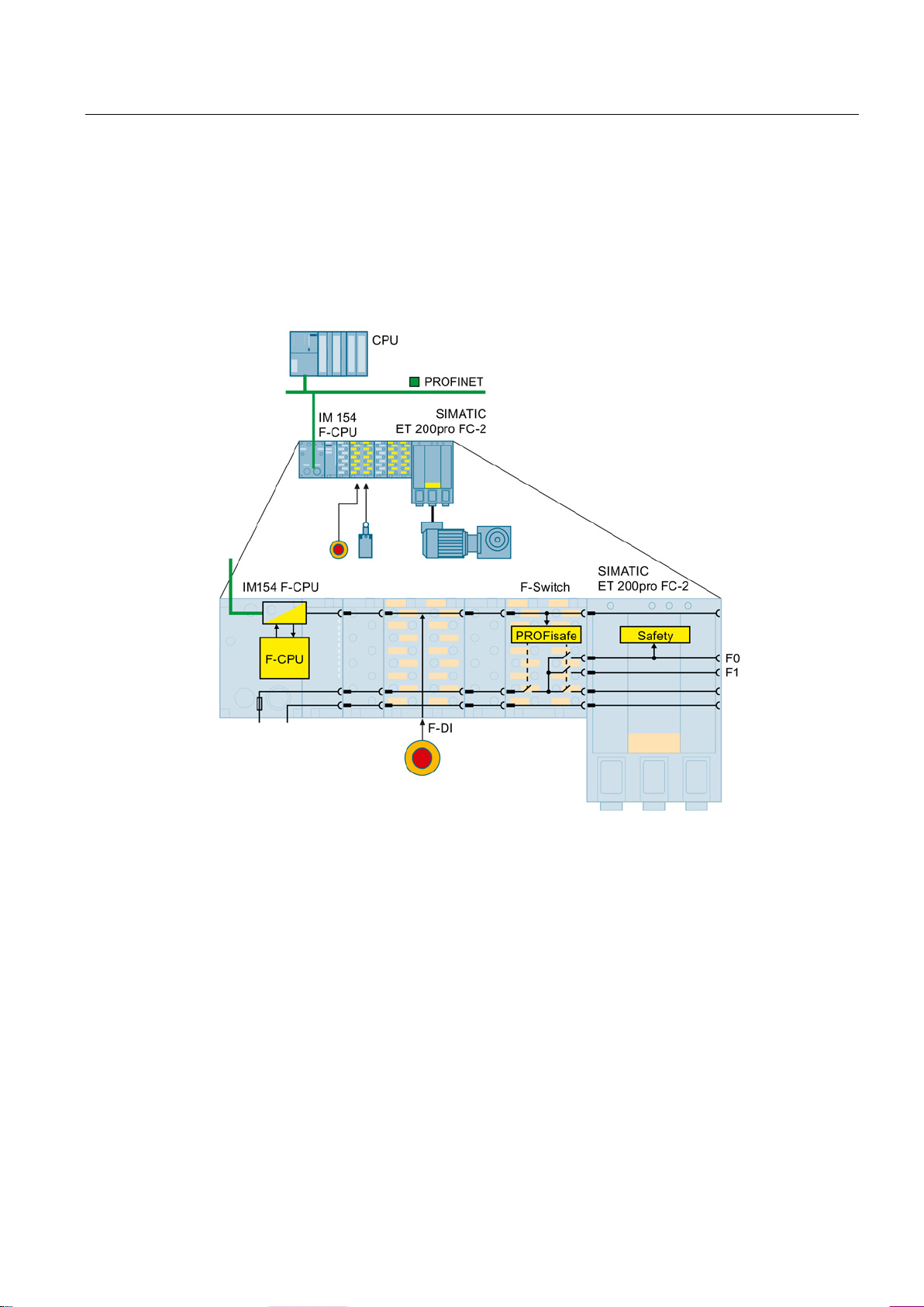
Installing
PROFIsafe communication within the SIMATIC ET 200pro
4.2 Connection via PROFIsafe
The SIMATIC-ET-200pro system allows safety-related communication, restricted to the
system:
● The ET-200pro system is node on the PROFIBUS or PROFINET.
● Within the ET-200pro system, the interface module with integrated fail-safe control (IM F-
CPU) controls the safety functions of the inverter via PROFIsafe.
Figure 4-5 Safety-related communication between an IM F-CPU and inverter within an ET 200pro,
e.g. on PROFINET
Safety Integrated - SINAMICS G110M, G120, G120C, G120D and SIMATIC ET 200pro FC-2
Function Manual, 04/2014, FW V4.7, A5E34261271B AA
45
Page 46
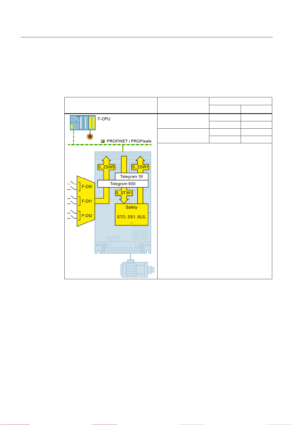
Installing
4.2.2
PROFIsafe telegrams
Overview using PROFINET / PROFIsafe as
example
Telegram
Process data (PZD)
PZD1
PZD2
Telegram 30
S_STW1
---
S_ZSW1
---
Telegram 900
S_STW1
S_STW5
S_ZSW1
S_ZSW5
S_STW: Safety control word; S_ZSW: Safety status word
4.2 Connection via PROFIsafe
Two telegrams are available for the data exchange via PROFIsafe between the inverter and
the higher-level controller:
Table 4- 1 PROFIsafe telegrams
PZD 1/1
PZD 2/2
The higher-level control selects the safety functions in
the inverter via the control word S_STW1. The inverter
uses the status word S_ZSW1 to report the status of
the safety functions to the controller.
Telegram 900 of the PROFIsafe profile also contains
control and status word 5. The inverter uses status
word S_ZSW5 to transfer the state of the safety digital
inputs to the control.
Safety Integrated - SINAMICS G110M, G120, G120C, G120D and SIMATIC ET 200pro FC-2
46 Function Manual, 04/2014, FW V4.7, A5E34261271B AA
Page 47

Installing
4.2.3
Control word 1 and status word 1 (basic functions)
Byte
Bit
Function
Comment
0
Select STO
1
Deselect STO
0
Select SS1
1
Deselect SS1
2 … 6
Not relevant
0
Do not acknowledge faults
1 → 0
Acknowledge "Internal event" for a 1 → 0 signal change
1 8 … 15
Not relevant
Byte
Bit
Function
Comment
0
STO is not active
1
STO is active
0
SS1 is not active
1
SS1 is active
2 … 6
Not relevant
0
Fault-free operation
1
The inverter signals an "internal event"
1 8 … 15
Not relevant
4.2 Connection via PROFIsafe
Table 4- 2 Control word 1 (bit 0 ... 15)
0 0 STO
1 SS1
7 Internal Event
ack
Table 4- 3 Status word 1 (bit 0 ... 15)
0 0 Power removed
1 SS1 active
7 Internal Event
Safety Integrated - SINAMICS G110M, G120, G120C, G120D and SIMATIC ET 200pro FC-2
Function Manual, 04/2014, FW V4.7, A5E34261271B AA
47
Page 48

Installing
4.2.4
Control word 1 and status word 1 (extended functions)
Byte
Bit
Function
Comment
0
Select STO
1
Deselect STO
0
Select SS1
1
Deselect SS1
2, 3 Not relevant
0
Select SLS
1
Deselect SLS
5, 6 Not relevant
0
Do not acknowledge faults
1 → 0
Acknowledge "Internal event" for a 1 → 0 signal change
0 Not relevant
Bit 10
Bit 9
Level 4
1
1
3 Not relevant
1
Deselect SDI with positive direction of rotation
0
Select SDI with negative direction of rotation
1
Deselect SDI with negative direction of rotation
6, 7 Not relevant
4.2 Connection via PROFIsafe
Table 4- 4 Control word 1 (bit 0 ... 15)
0 0 STO
1 SS1
4 SLS
7 Internal event
ack
1
1 SLS level bit 0 Select SLS level
2 SLS level bit 1
Level 1
Level 2
Level 3
0
0
1
0
1
0
4 SDI positive 0 Select SDI with positive direction of rotation
5 SDI negative
Safety Integrated - SINAMICS G110M, G120, G120C, G120D and SIMATIC ET 200pro FC-2
48 Function Manual, 04/2014, FW V4.7, A5E34261271B AA
Page 49

Installing
Byte
Bit
Function
Comment
0
STO is not active
1
STO is active
0
SS1 is not active
1
SS1 is active
2, 3 Not relevant
0
SLS is not active
1
SLS is active
5, 6 Not relevant
0
Fault-free operation
1
The inverter signals an "internal event"
0 Not relevant
Bit 10
Bit 9
Level 4
1
1
3 Not relevant
1
SDI positive direction of rotation is active
1
SDI negative direction of rotation is active
6 Not relevant
value
value
4.2 Connection via PROFIsafe
Table 4- 5 Status word 1 (bit 0 ... 15)
0 0 Power removed
1 SS1 active
4 SLS active
7 Internal Event
1
1 SLS level bit 0 SLS level is active
2 SLS level bit 1
Level 1
Level 2
Level 3
0
0
1
0
1
0
4 SDI positive
active
5 SDI negative
active
7 Status SSM 0 Absolute value of the speed is greater than the SSM limit
0 SDI positive direction of rotation is not active
0 SDI negative direction of rotation is not active
1 Absolute value of the speed is less than the SSM limit
Safety Integrated - SINAMICS G110M, G120, G120C, G120D and SIMATIC ET 200pro FC-2
Function Manual, 04/2014, FW V4.7, A5E34261271B AA
49
Page 50

Installing
4.2.5
Control word 5 and status word 5
Byte
Bit
Function
Comment
15
Byte
Bit
Function
Comment
SINAMICS
G120
SINAMICS
G120D
7
8
Status of safety inputs
0
LOW signal (0 V)
1
HIGH signal (24 V)
9
0
LOW signal (0 V)
1
HIGH signal (24 V)
10
0
LOW signal (0 V)
1
HIGH signal (24 V)
15
4.2 Connection via PROFIsafe
Table 4- 6 Control word 5 (bit 0 ... 15)
0 … 1 0
…
Table 4- 7 Status word 5 (bit 0 ... 15)
0 0
…
1
11
…
Reserved
Reserved
Reserved
Assign the value 0 to the reserved bits.
-
-
At terminals 5
and 6
At terminals 7
and 8
At terminals
16 and 17
At pins X7.2
and X7.4
At pins X8.2
and X8.4
At pins X9.2
and X9.4
An overview of the safety inputs can be found in section Safety inputs (Page 51).
Safety Integrated - SINAMICS G110M, G120, G120C, G120D and SIMATIC ET 200pro FC-2
50 Function Manual, 04/2014, FW V4.7, A5E34261271B AA
If one of the two following conditions is satisfied, the inverter sets the particular bit 8 … 10 in
the status word 5 to zero, independent of the voltage levels that are present:
● The corresponding safety input is not used.
● The inverter has deactivated the relevant safety input due to a discrepancy.
Page 51
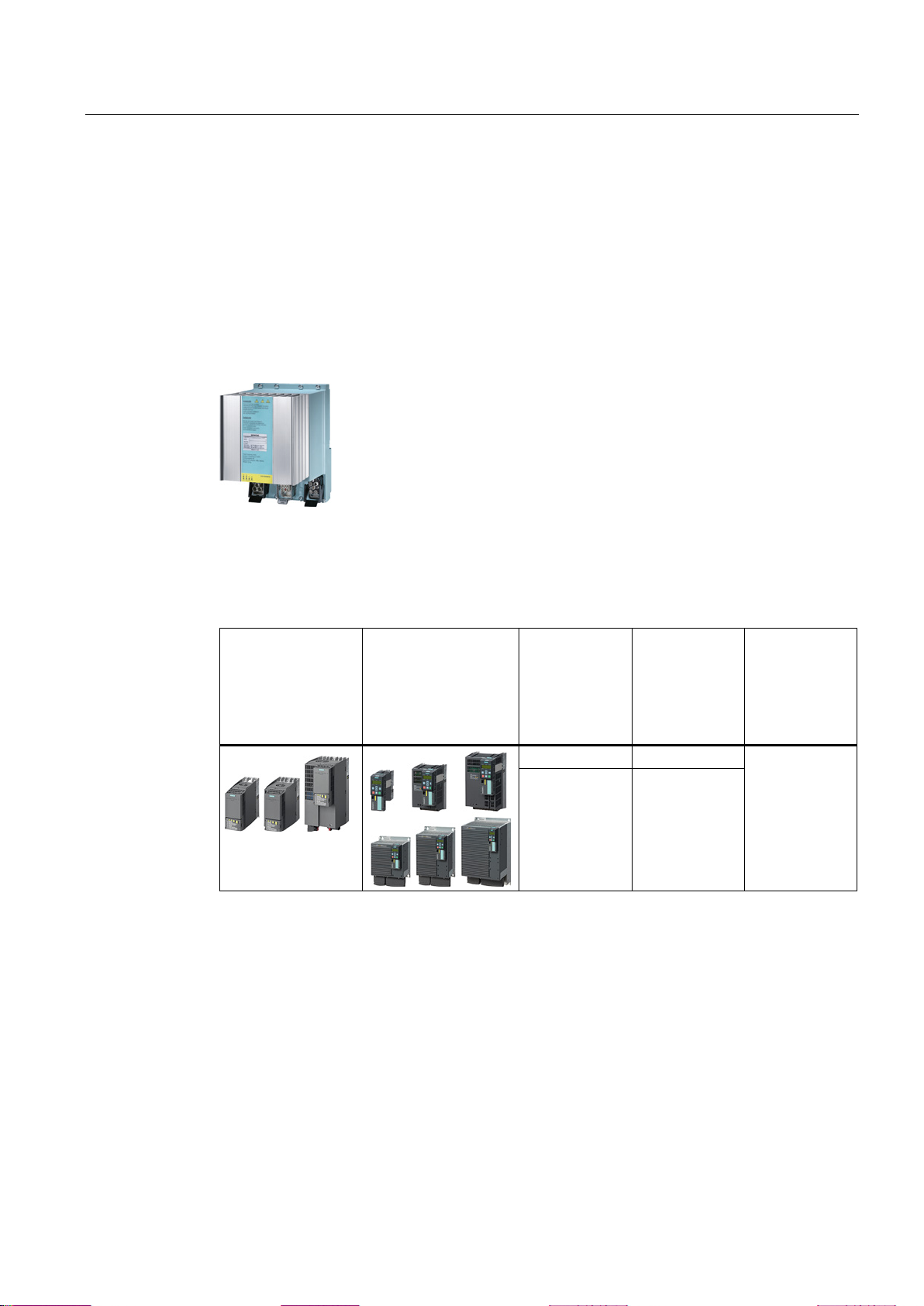
Installing
4.3
Activation via F-DI
4.3.1
Safety inputs
The SIMATIC ET
accessible safety inputs. If you wish to control the safety functions of
this inverter via an input within the ET-200pro station, then you will need
the F
Wiring examples are provided in the following section, also see
examples
Assignment of safety inputs
SINAMICS G120C
SINAMICS G120
with
CU240E-2
CU240E-2 DP
CU240E-2 PN
Control Units
Terminal strip
Digital input
Safety input
16
DI 4
4.3 Activation via F-DI
In the factory setting of the inverter, the safety inputs are not assigned to the integrated
safety functions. Only when commissioning do you define whether you use, for example,
digital inputs DI 4 and DI 5 for standard functions, or by combining them, you create a safety
input.
200pro FC-2 converter does not have directly
-RSM or F-Switch module.
Wiring
(Page 54).
Table 4- 8 Inverters (chassis units, IP20) with only one safety input
F-DI 0
17 DI 5
Safety Integrated - SINAMICS G110M, G120, G120C, G120D and SIMATIC ET 200pro FC-2
Function Manual, 04/2014, FW V4.7, A5E34261271B AA
51
Page 52
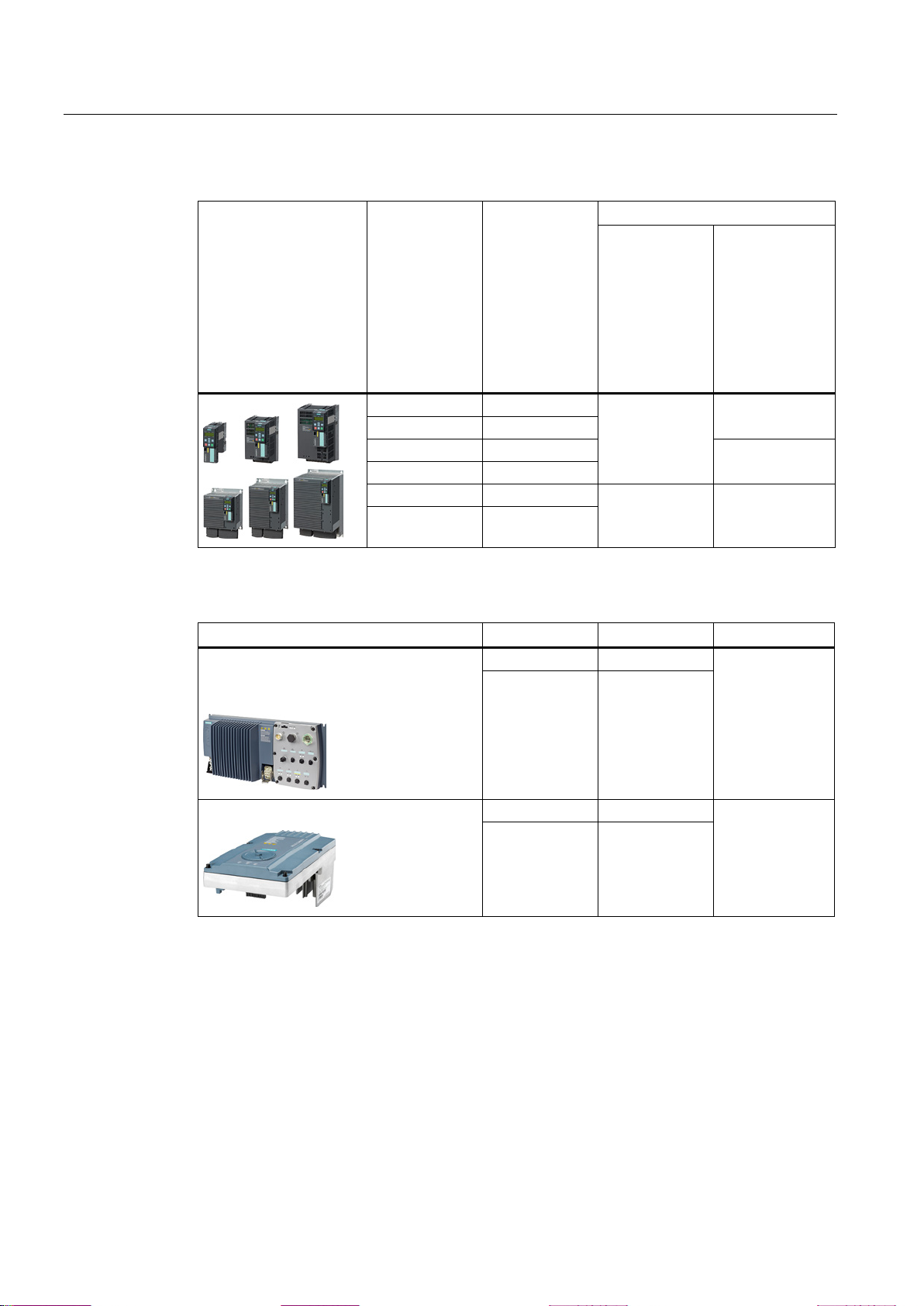
Installing
SINAMICS G120
with
CU240E-2 F
CU240E-2 DP-F
CU240E-2 PN-F
CU250S-2
CU250S-2 CAN
CU250S-2 DP
CU250S-2 PN Control
Units
Terminal strip
Digital input
Safety inputs
Basic functions
Extended
functions
5
DI 0
6
DI 1
7
DI 2
8
DI 3
16
DI 4
Connector.pin
Digital input
Safety input
X9.4
DI 4
X8.4
DI 2
4.3 Activation via F-DI
Table 4- 9 Inverters (chassis units IP20) with several safety inputs
- F-DI 0
F-DI 1
F-DI 0 F-DI 2
17 DI 5
Table 4- 10 Inverters for cabinet-free installation (IP65) with only one safety input
SINAMICS G120D with
CU240D-2 DP
CU240D-2 PN Control Units
X9.2 DI 5
F-DI 0
SINAMICS G110M
F-DI 0
X8.2 DI 3
Safety Integrated - SINAMICS G110M, G120, G120C, G120D and SIMATIC ET 200pro FC-2
52 Function Manual, 04/2014, FW V4.7, A5E34261271B AA
Page 53
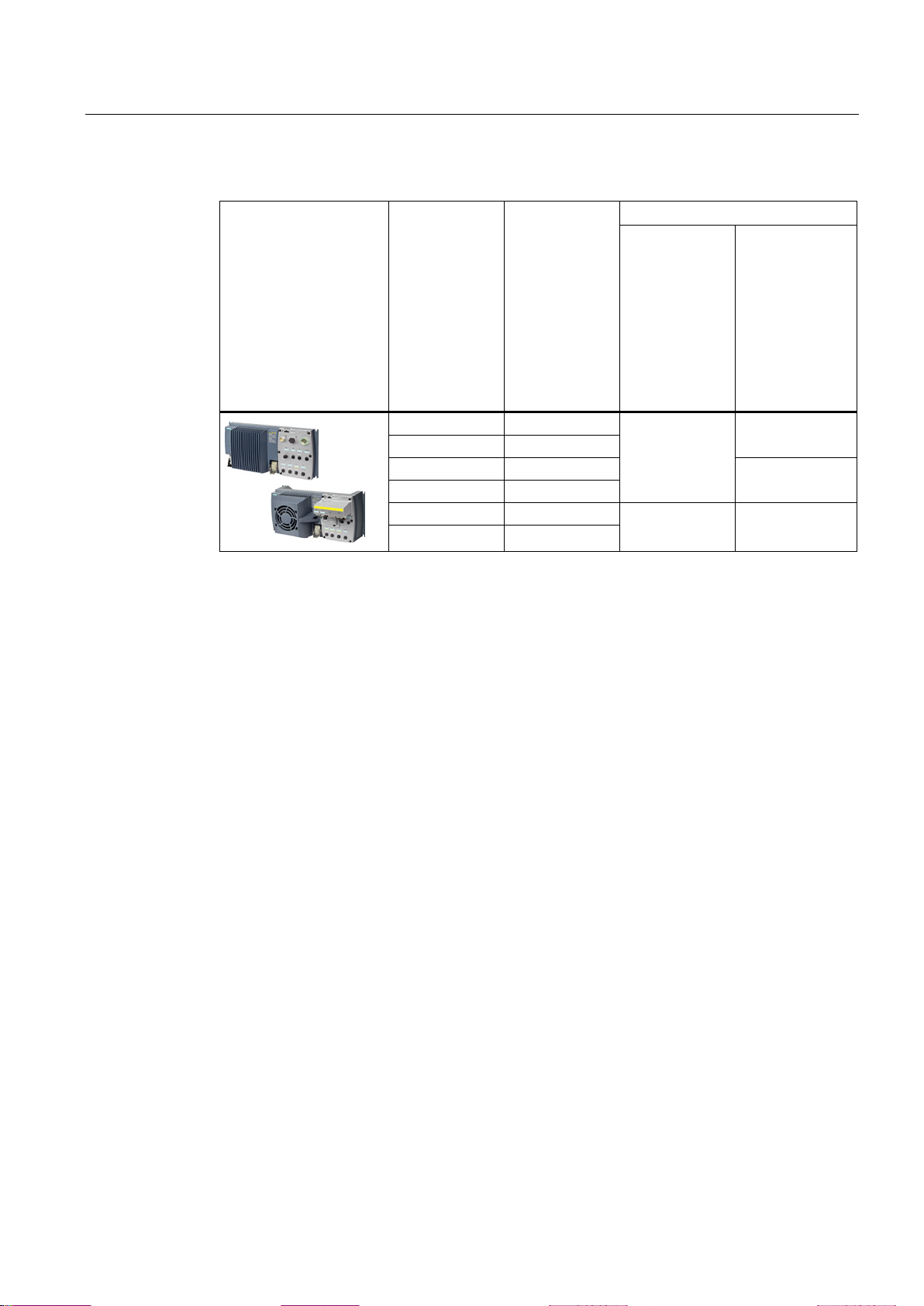
Installing
SINAMICS G120D
with
CU240D-2 DP-F
CU240D-2 PN-F
CU240D-2 PN-F PP
CU240D-2 PN-F FO
CU250D-2 DP-F
CU250D-2 PN-F
CU250D-2 PN-F PP
CU250D-2 PN-F FO
Control Units
Connector.pin
Digital input
Safety inputs
Basic functions
Extended
functions
X7.4
DI 0
X7.2
DI 1
X8.4
DI 2
X8.2
DI 3
X9.4
DI 4
What devices can be connected?
Signal states
Fault detection
4.3 Activation via F-DI
Table 4- 11 Inverters for cabinet-free installation (IP65) with several safety inputs
- F-DI 0
F-DI 1
F-DI 0 F-DI 2
X9.2 DI 5
Safety-related signals, e.g. the switching state of a sensor, must be wired using two
channels with one safety input. The inverter evaluates the signal on two separate signal
paths.
The safety-related input is designed for the following devices:
● Connection of safety sensors, e.g. emergency stop command devices or light curtains.
● Connection of pre-processing devices, e.g. fail-safe control systems and safety relays.
The inverter expects signals with the same state at its safety-related input:
● High signal: The safety function is deselected.
● Low signal: The safety function is selected.
The inverter evaluates deviations in the two signals of the safety-related input. The inverter
thus detects, for example the following faults:
● Cable break
Safety Integrated - SINAMICS G110M, G120, G120C, G120D and SIMATIC ET 200pro FC-2
Function Manual, 04/2014, FW V4.7, A5E34261271B AA
● Defective sensor
The inverter cannot detect the following faults:
● Cross-circuit of the two cables
● Short-circuit between signal cable and 24 V power supply
53
Page 54
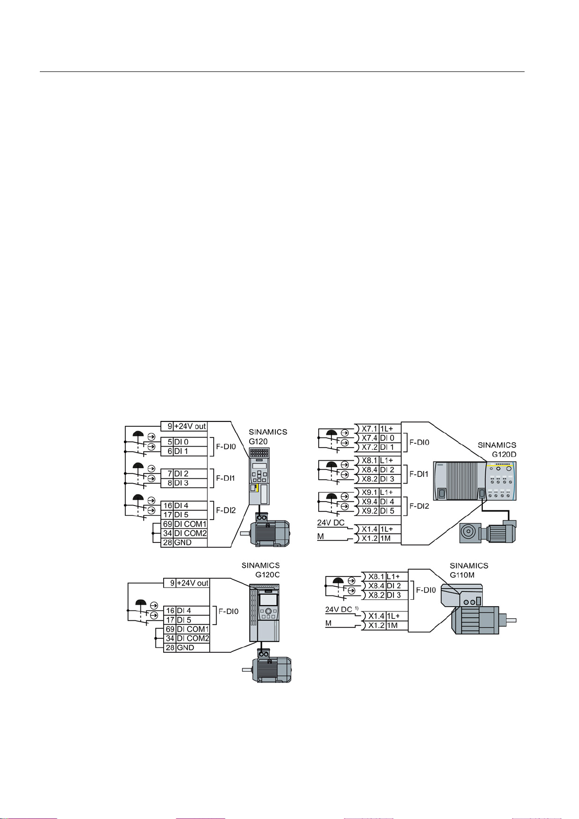
Installing
Special measures when establishing connections
4.3.2
Wiring examples
4.3.2.1
Connecting sensors
Electromechanical sensor
The inverter provides the supply voltage
The 24 V supply is not required when using the G110M "24 V Power Module" option
4.3 Activation via F-DI
When routing cables over longer distances, e.g. between remote control cabinets, you have
the following options to reduce the risk of damaged cables when your plant or machine is
operating:
● Use shielded cables with grounded shield.
● Lay signal cables in steel pipes.
On the following pages, you will find examples of interconnecting safety digital inputs in
accordance with PL d to EN 13849-1 and SIL 2 to IEC 61508.
If there is a risk of cross-circuits or short-circuits, the cables between the sensor and the
inverter must be protected, for example, by routing them in a steel tube.
1)
Figure 4-6 Connecting an electromechanical sensor to the inverter power supply
Safety Integrated - SINAMICS G110M, G120, G120C, G120D and SIMATIC ET 200pro FC-2
54 Function Manual, 04/2014, FW V4.7, A5E34261271B AA
Page 55
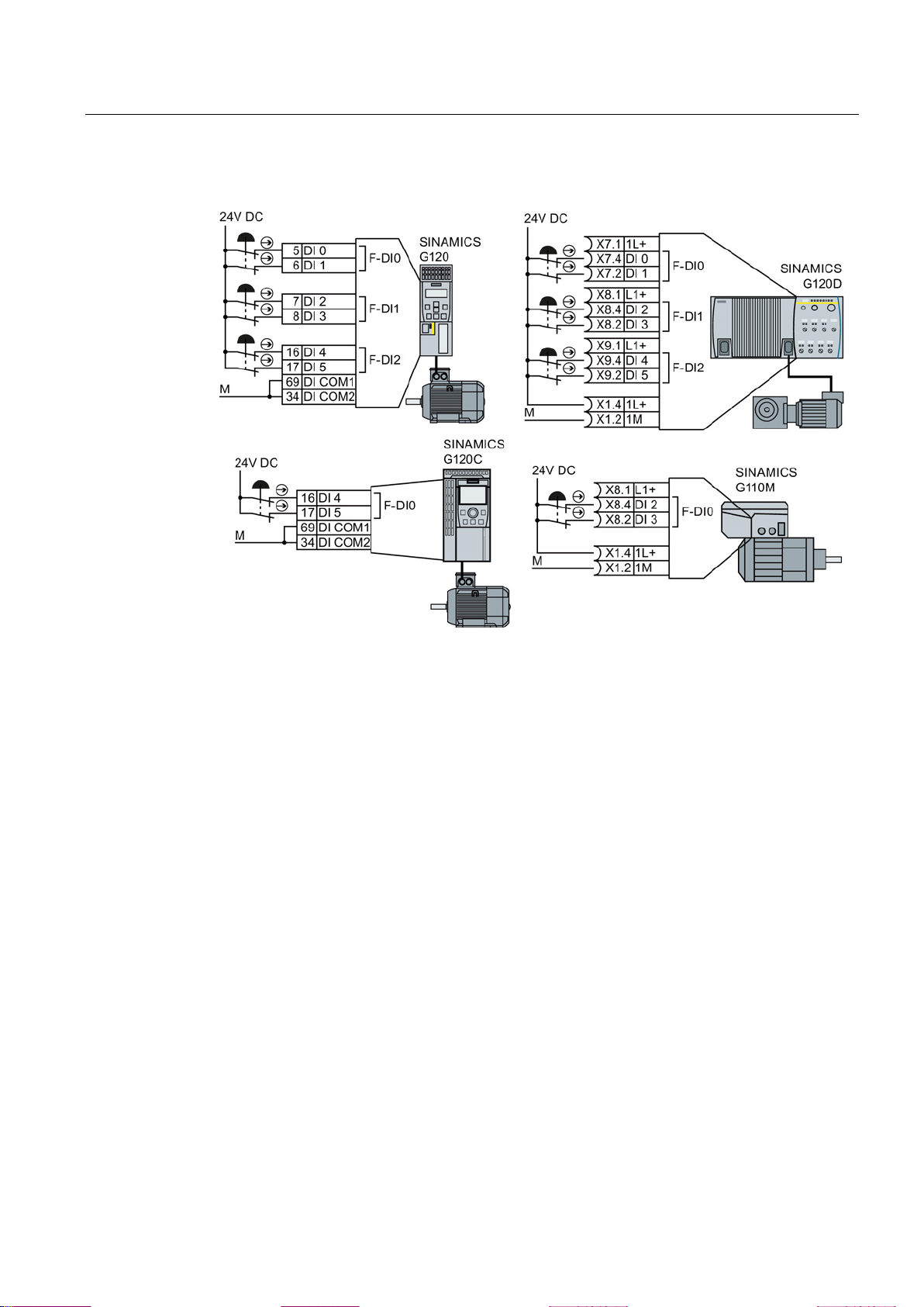
Installing
External power supply
4.3 Activation via F-DI
Figure 4-7 Connecting an electromechanical sensor to an external power supply
Safety Integrated - SINAMICS G110M, G120, G120C, G120D and SIMATIC ET 200pro FC-2
Function Manual, 04/2014, FW V4.7, A5E34261271B AA
55
Page 56
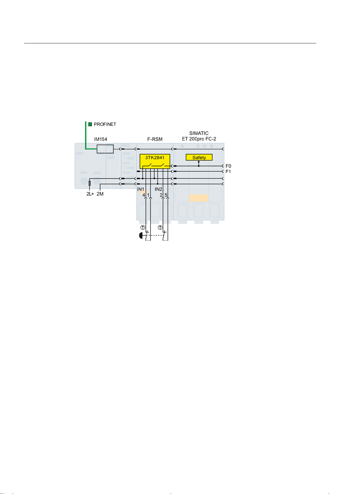
Installing
SIMATIC ET 200pro
4.3 Activation via F-DI
The SIMATIC ET 200pro FC converter does not have its own inputs. If you wish to directly
control the safety functions of the ET 200pro FC-2 via a sensor, then you will require the
F-RSM or the F-Switch module.
The F-RSM module evaluates the sensor, and switches the "F0 rail" in the backplane bus of
the ET-200pro system. The inverter evaluates the F0 rail using an internal, safety input.
Figure 4-8 Directly controlling the safety functions in the ET 200pro FC-2 converter via the F-RSM
module
The F-Switch module evaluates the sensor, and also switches the "F0 rail" in the backplane
bus of the ET-200pro system. The inverter evaluates the F0 rail using an internal, safety
input.
Safety Integrated - SINAMICS G110M, G120, G120C, G120D and SIMATIC ET 200pro FC-2
56 Function Manual, 04/2014, FW V4.7, A5E34261271B AA
Page 57
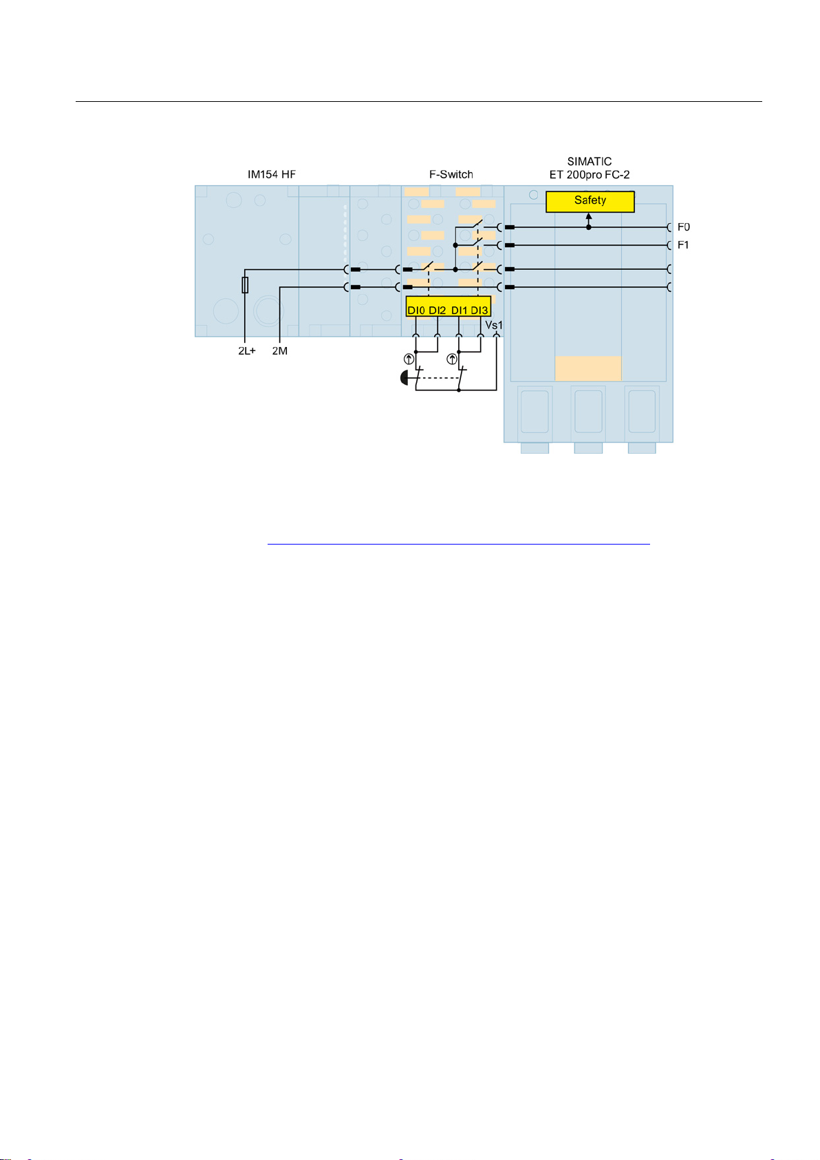
Installing
Series-connected electromechanical sensors
4.3 Activation via F-DI
Figure 4-9 Directly controlling the safety functions in the ET 200pro FC-2 converter via the F-Switch
module
Additional installation options for the F-Switch and F-RSM modules are listed in the following
FAQ: FAQ (http://support.automation.siemens.com/WW/view/en/26694409).
You may connect Emergency Stop control devices in series if it can be ruled out that the
Emergency Stop command devices are simultaneously actuated. The simultaneous failure of
Emergency Stop control devices connected in series can generally be ruled out.
According to IEC 62061 (SIL) and EN ISO 13849-1 (PL), position switches of protective
doors may also connected in series.
Exception: If several protective doors are regularly opened at the same time, it is not
possible for faults to be detected, which means that the position switches must not be
connected in series.
If there is a risk of cross-circuits or short-circuits, the cables between the sensor and the
inverter must be protected, for example, by routing them in a steel tube.
Safety Integrated - SINAMICS G110M, G120, G120C, G120D and SIMATIC ET 200pro FC-2
Function Manual, 04/2014, FW V4.7, A5E34261271B AA
57
Page 58
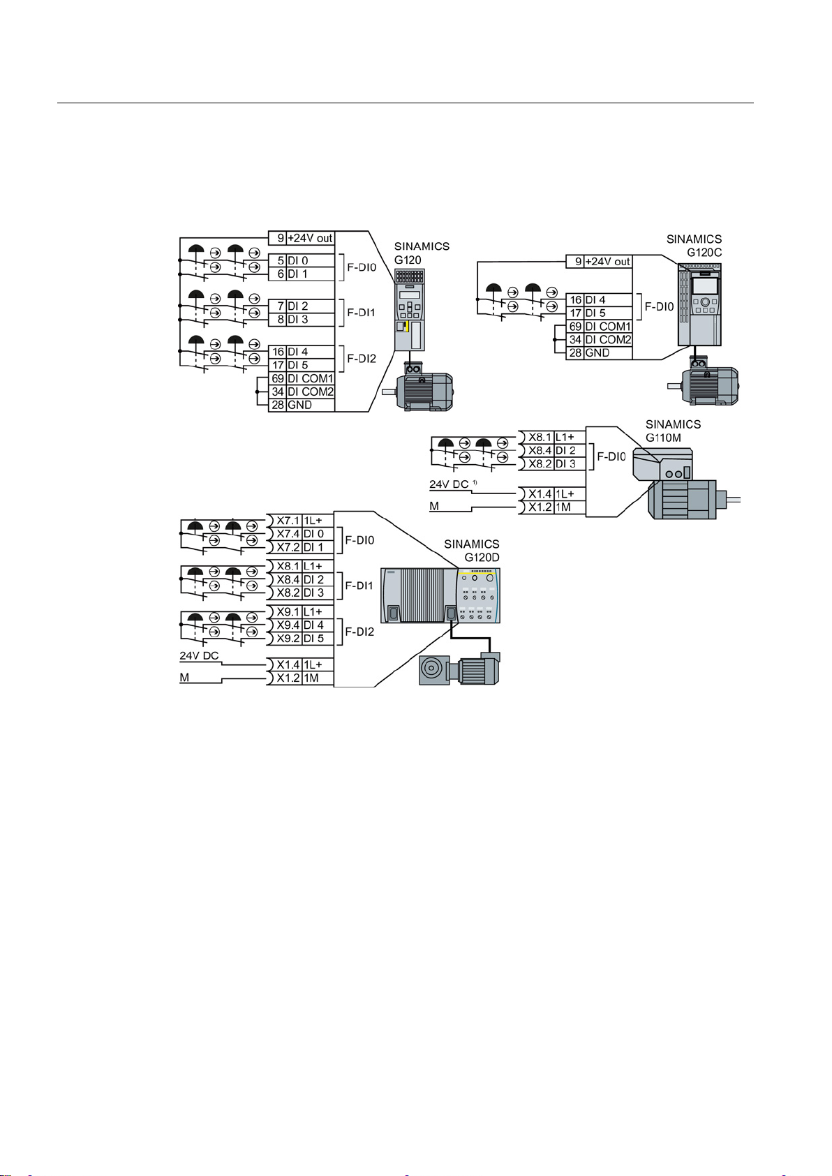
Installing
The inverter provides the supply voltage
4.3 Activation via F-DI
Connect the 24 V supply of the inverter to the sensors and connect the reference potentials
of the inputs used to GND.
1
The 24 V supply is not required when using the G110M "24 V Power Module" option
)
Figure 4-10 Connecting electromechanical sensors to the inverter power supply in series
Safety Integrated - SINAMICS G110M, G120, G120C, G120D and SIMATIC ET 200pro FC-2
58 Function Manual, 04/2014, FW V4.7, A5E34261271B AA
Page 59
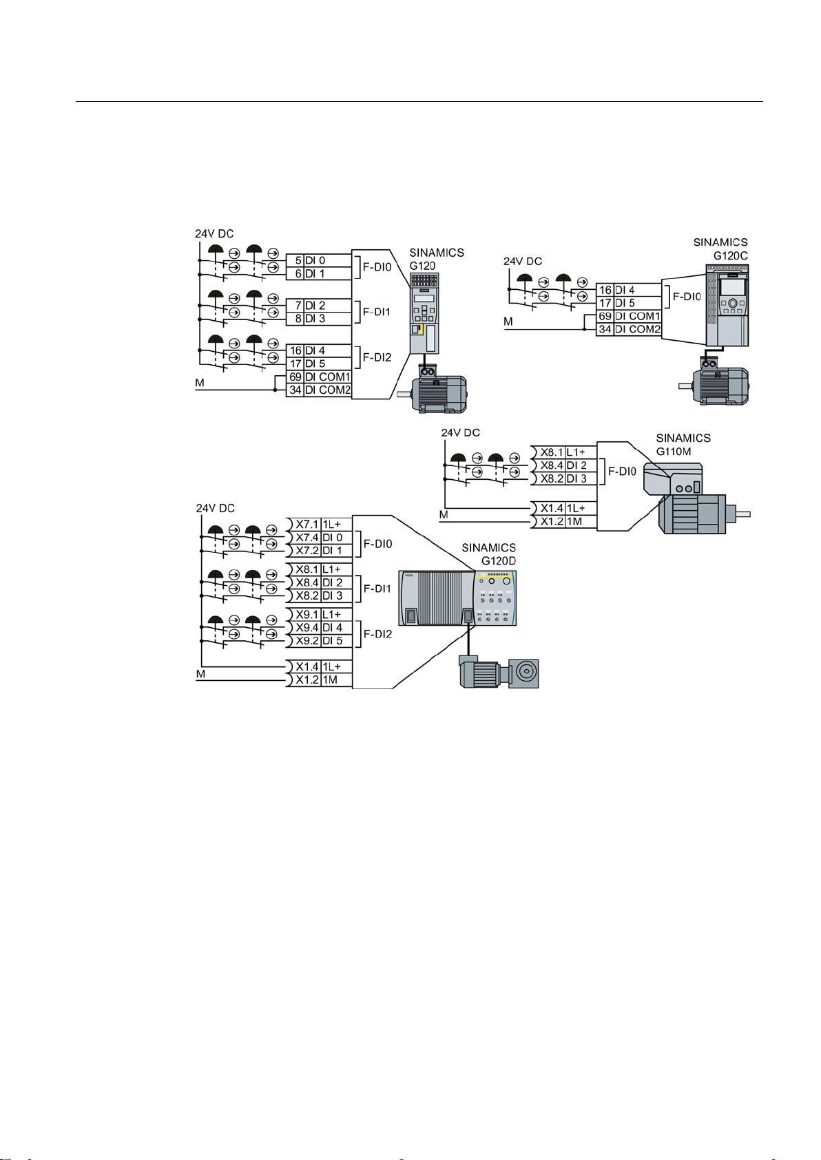
Installing
External power supply
4.3 Activation via F-DI
Connect the external power supply to the sensors and connect the reference potentials of
the inputs used to the reference potential of the external power supply.
Figure 4-11 Connecting electromechanical sensors to an external power supply in series
Safety Integrated - SINAMICS G110M, G120, G120C, G120D and SIMATIC ET 200pro FC-2
Function Manual, 04/2014, FW V4.7, A5E34261271B AA
59
Page 60
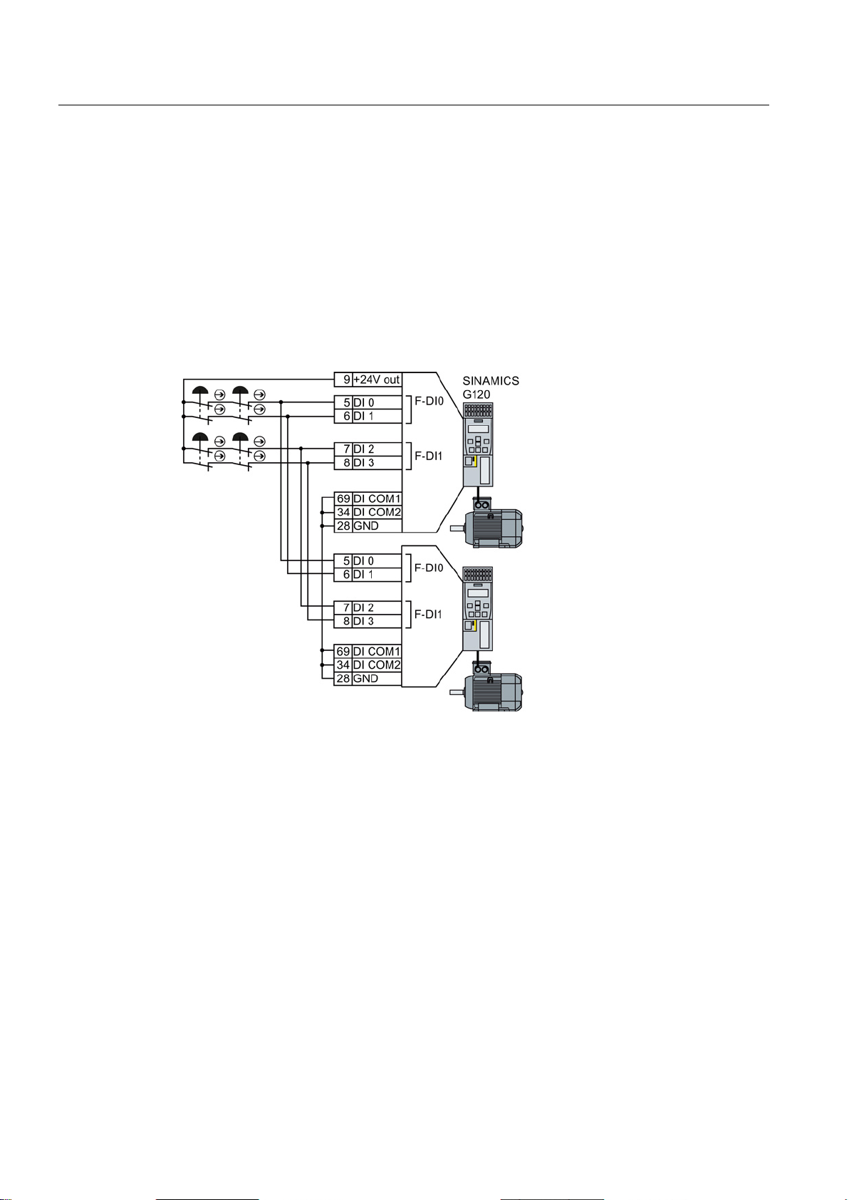
Installing
Activating several inverters simultaneously
The converter provides the supply voltage
4.3 Activation via F-DI
You may activate the safety functions of several converters simultaneously with one or
several series-connected safety sensors.
If there is a risk of cross-circuits or short-circuits, the cables between the sensor and the
converter must be protected, for example, by routing them in a steel tube.
Connect the 24 V supply of the converter to the sensors and connect the reference
potentials of the inputs used to GND.
Figure 4-12 Simultaneous activation of several converters with converter power supply
Safety Integrated - SINAMICS G110M, G120, G120C, G120D and SIMATIC ET 200pro FC-2
60 Function Manual, 04/2014, FW V4.7, A5E34261271B AA
Page 61
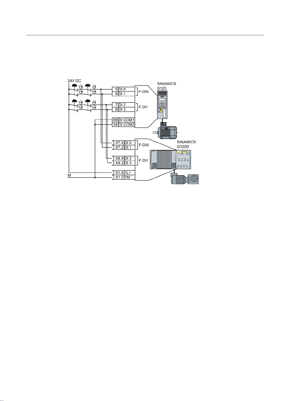
Installing
External power supply
4.3 Activation via F-DI
Connect the external power supply to the sensors and connect the reference potentials of
the inputs used to the reference potential of the external power supply.
Figure 4-13 Simultaneous activation of several converters with external power supply
Safety Integrated - SINAMICS G110M, G120, G120C, G120D and SIMATIC ET 200pro FC-2
Function Manual, 04/2014, FW V4.7, A5E34261271B AA
61
Page 62

Installing
4.3.2.2
Connecting pre-processing devices
3TK28 safety relay
4.3 Activation via F-DI
If you use safety relays with electronic enabling circuits, the relays must feature outputs that
switch to P potential. The safety relay switches the 24 V supply line to the converter but not
the ground return line.
Safety relays with relay enabling circuits are only permitted if, as a minimum, they have an
internal two-channel configuration.
The following pages describe a number of typical circuits for various types of safety relay.
Exactly how these are interconnected depends on whether the safety relay and the converter
are housed in the same or separate control cabinets.
The typical circuits described on the following pages are based on safety relays with relay
enabling circuits. Safety relays with semiconductor enabling circuits can also be used.
The diagrams only show how the safety relay and inverter are interconnected. Information
providing full details of how the safety relay is wired can be found in the product-specific
documentation: SIRIUS 3TK28 safety relays
(http://support.automation.siemens.com/WW/view/en/26414637/133300).
Safety Integrated - SINAMICS G110M, G120, G120C, G120D and SIMATIC ET 200pro FC-2
62 Function Manual, 04/2014, FW V4.7, A5E34261271B AA
Page 63
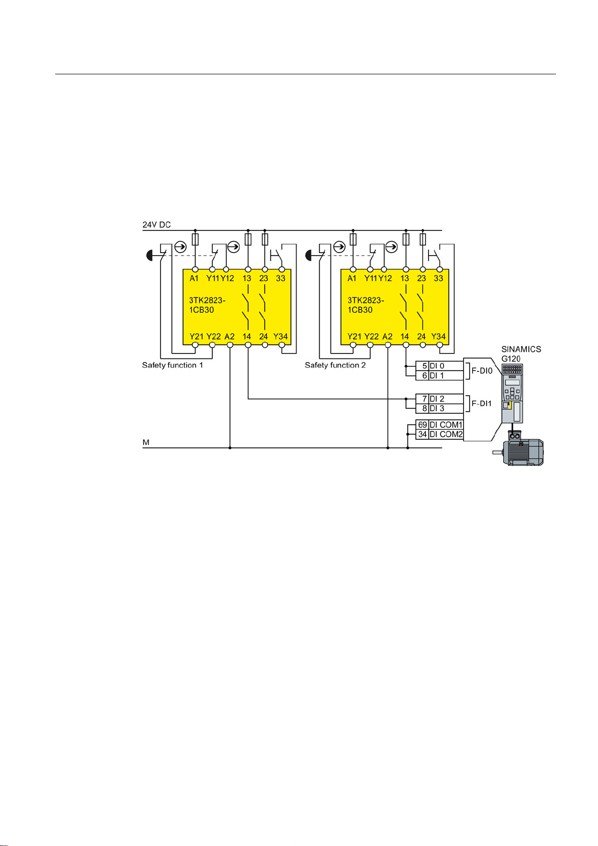
Installing
Components in the same control cabinet
4.3 Activation via F-DI
A control cabinet that has been designed and wired correctly does not contain any damaged
wiring or cross circuits.
Under the assumption that the preprocessing devices switch the output used twice (involves
two contacts in series), within a control cabinet you can interconnect the safety relay and
inverter through a single channel cable connection. The two terminals of the safety input
must be connected to each other at the inverter.
Figure 4-14 Interconnecting the inverter and safety relay within the same control cabinet
Safety Integrated - SINAMICS G110M, G120, G120C, G120D and SIMATIC ET 200pro FC-2
Function Manual, 04/2014, FW V4.7, A5E34261271B AA
63
Page 64
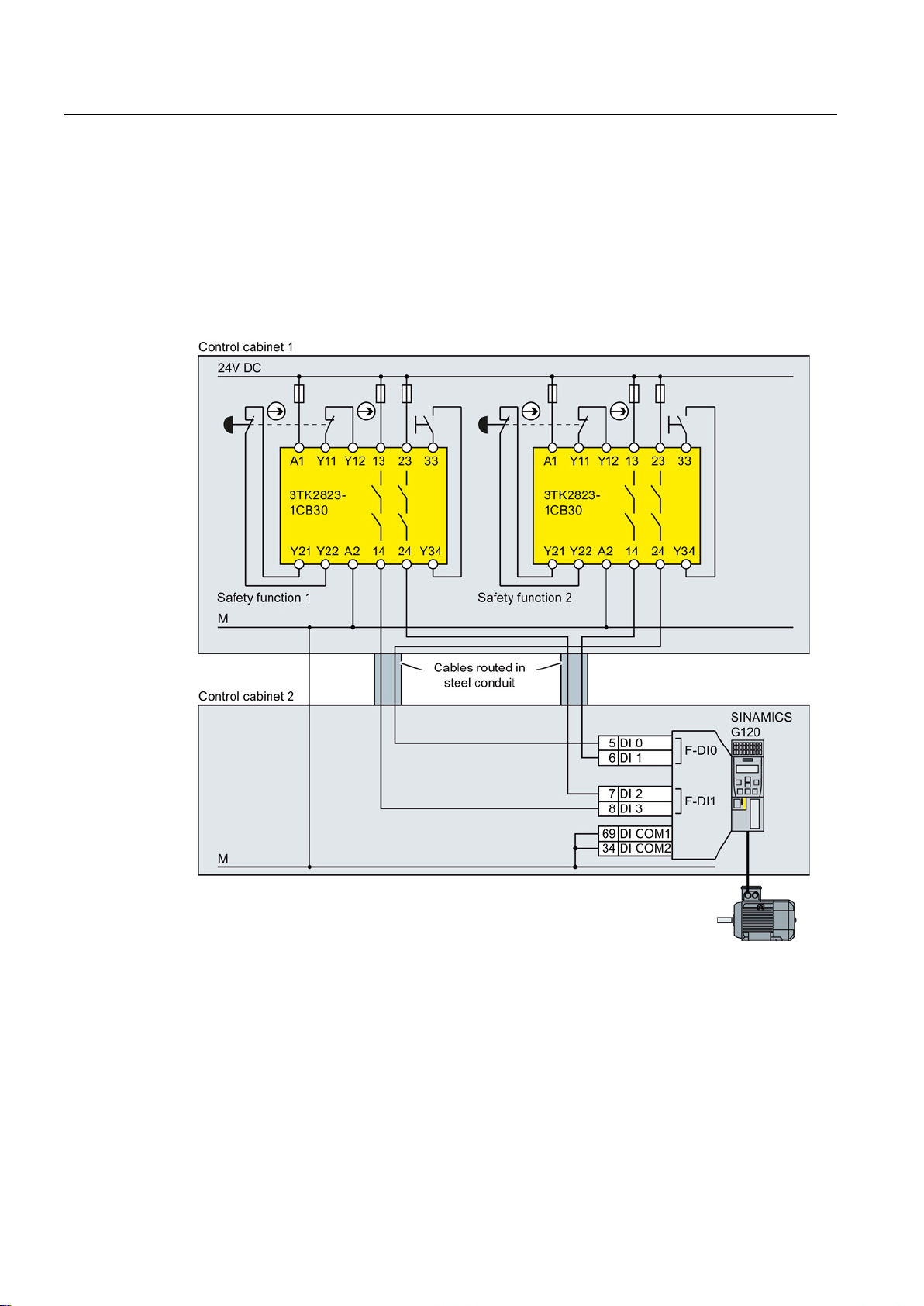
Installing
Components in separate control cabinets
4.3 Activation via F-DI
If the components are located in separate control cabinets, the wiring between the safety
relay and safety inputs in the inverter must be installed such that it is protected against cross
and short-circuits.
Transfer the two signals for activating a safety function via wires in separate lines. In the
example, the signals for terminal 5 and 7 are transferred via the first wire. The signals for
terminal 6 and 8 are then transferred via the second wire.
Figure 4-15 Interconnecting the inverter and safety relay in separate control cabinets
Safety Integrated - SINAMICS G110M, G120, G120C, G120D and SIMATIC ET 200pro FC-2
64 Function Manual, 04/2014, FW V4.7, A5E34261271B AA
Page 65
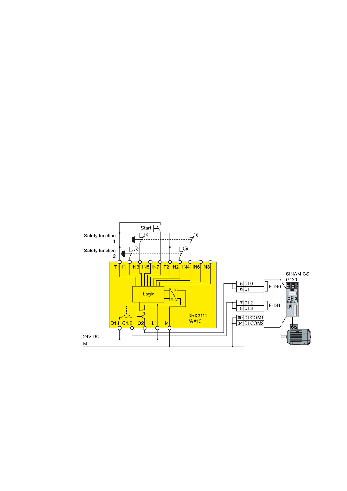
Installing
3RK3 Modular Safety System
Components in the same control cabinet
4.3 Activation via F-DI
You can use both the safety outputs in the MSS Basic central unit of the 3RK3 modular
safety system as well as the outputs in the EM 2/4F-DI 2F-DO expansion module to activate
the F-DIs of the inverter.
The safety relay outputs of the EM 2/4F-DI 1/2F-RO expansion module must not be used
because these only have a single-channel configuration.
The diagrams only show how the 3RK3 Modular Safety System and inverter are
interconnected. Information providing full details of how the 3RK3 Modular Safety System
are wired can be found in the product-specific documentation: SIRIUS 3RK3 Modular Safety
System (http://support.automation.siemens.com/WW/view/en/26412499/133300).
A control cabinet that has been designed and wired correctly does not contain any damaged
wiring or cross circuits.
Under the assumption that the preprocessing devices switch the output used twice (involves
two contacts in series), within a control cabinet you can interconnect the safety relay and
inverter through a single channel cable connection. The two terminals of the safety input
must be connected to each other at the inverter.
Figure 4-16 Interconnecting the inverter and Modular Safety System within the same control cabinet
Safety Integrated - SINAMICS G110M, G120, G120C, G120D and SIMATIC ET 200pro FC-2
Function Manual, 04/2014, FW V4.7, A5E34261271B AA
65
Page 66
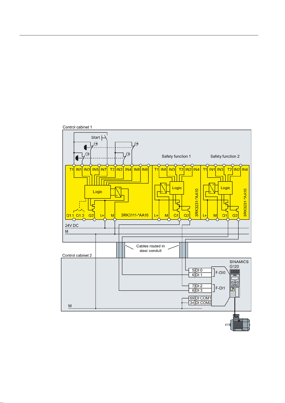
Installing
Components in separate control cabinets
4.3 Activation via F-DI
If the components are located in separate control cabinets, the wiring between the Modular
Safety System and the F-DIs on the inverter must be installed such that it is protected
against cross and short-circuits.
Transfer the two signals for activating a safety function via wires in separate lines. In the
example, the signals for terminal 5 and 7 are transferred via the first wire. The signals for
terminal 6 and 8 are then transferred via the second wire.
If you want to use the safety outputs of the 3RK3 central unit for transferring signals via two
channels, inverter discrepancy monitoring must be adapted to the different switching times of
the electronic output and relay contact.
Figure 4-17 Interconnecting the inverter and Modular Safety System in separate control cabinets
Safety Integrated - SINAMICS G110M, G120, G120C, G120D and SIMATIC ET 200pro FC-2
66 Function Manual, 04/2014, FW V4.7, A5E34261271B AA
Page 67
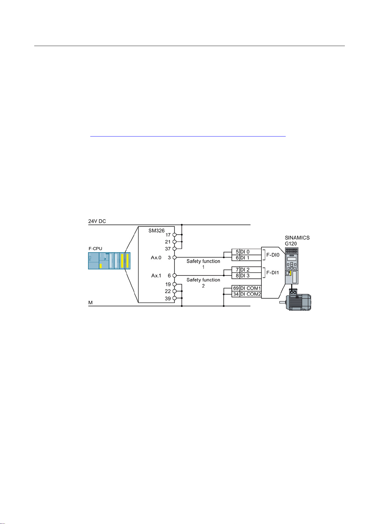
Installing
S7-300 I/O modules
Components in the same control cabinet
4.3 Activation via F-DI
Safety outputs that switch to P potential are required for activating the safety digital inputs of
the SINAMICS G120. From the S7-300 range, the SM326 DO 10 x 24 V / 2 A PP I/O module
fulfills this requirement.
The diagrams only show how the I/O module and inverter are interconnected. Information
providing full details of how the I/O module is wired can be found in the product-specific
documentation: S7-300
(http://support.automation.siemens.com/WW/view/en/10805159/133300).
A control cabinet that has been designed and wired correctly does not contain any damaged
wiring or cross circuits.
Under the assumption that the preprocessing devices switch the output used twice (involves
two contacts in series), within a control cabinet you can interconnect the I/O module SM326
and inverter through a single channel cable connection. The two terminals of the safety input
must be connected to each other at the inverter.
Figure 4-18 Interconnecting the inverter and SM326 I/O module within the same control cabinet
Safety Integrated - SINAMICS G110M, G120, G120C, G120D and SIMATIC ET 200pro FC-2
Function Manual, 04/2014, FW V4.7, A5E34261271B AA
67
Page 68
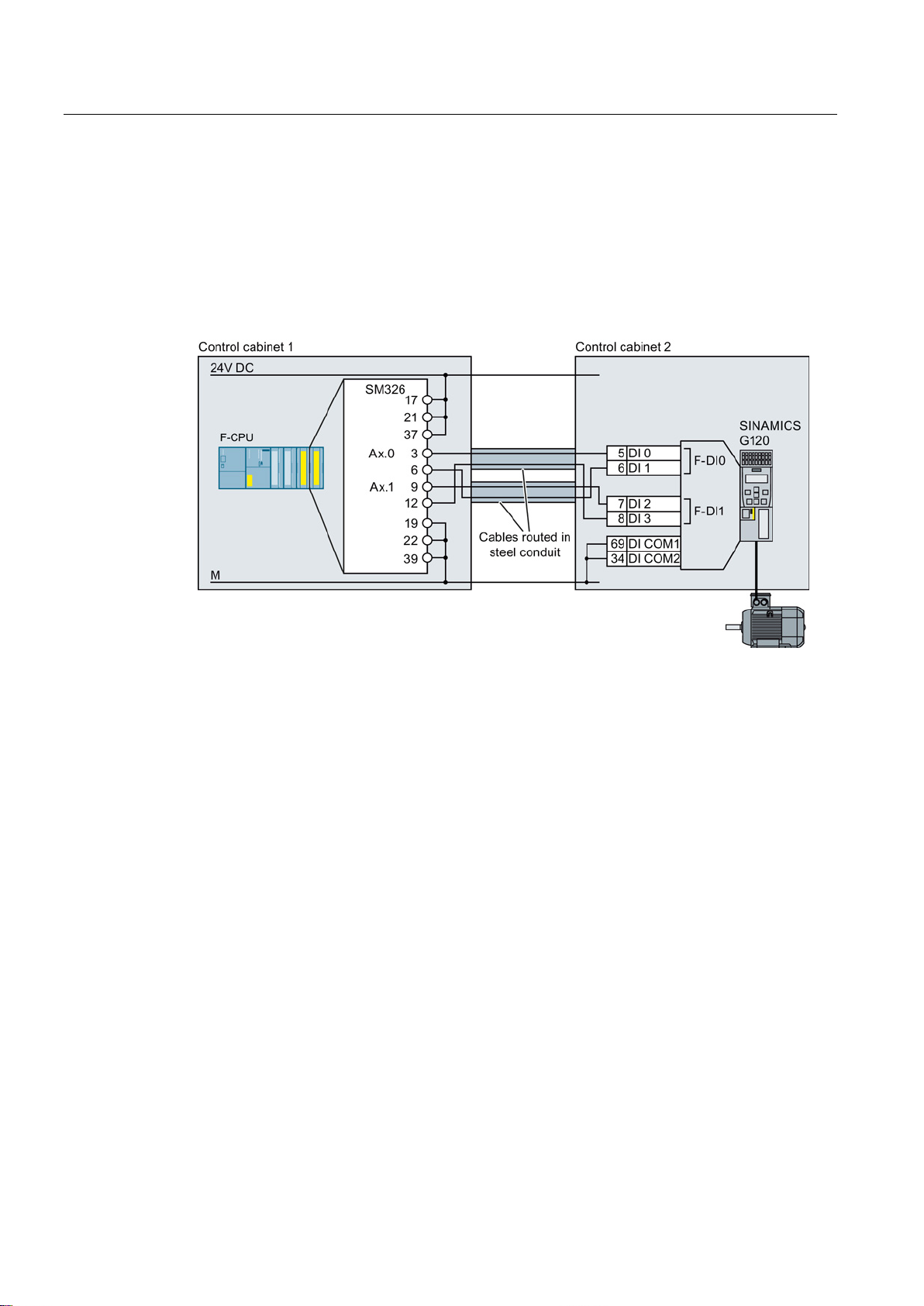
Installing
Components in separate control cabinets
4.3 Activation via F-DI
If the components are located in separate control cabinets, the wiring between the SM326
I/O module and the F-DIs on the inverter must be installed such that it is protected against
cross and short-circuits.
Transfer the two signals for activating a safety function via wires in separate lines. In the
example, the signals for terminal 5 and 7 are transferred via the first wire. The signals for
terminal 6 and 8 are then transferred via the second wire.
Figure 4-19 Interconnecting the inverter and SM326 I/O module in separate control cabinets
Safety Integrated - SINAMICS G110M, G120, G120C, G120D and SIMATIC ET 200pro FC-2
68 Function Manual, 04/2014, FW V4.7, A5E34261271B AA
Page 69
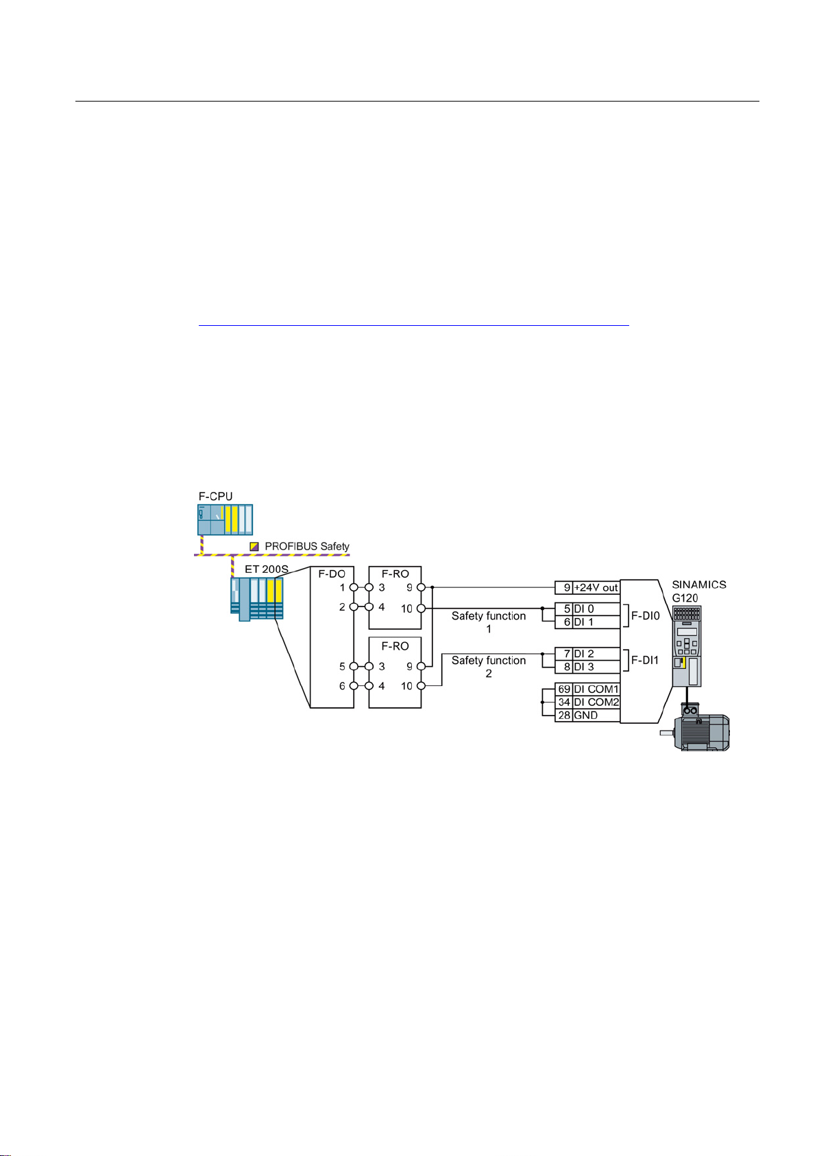
Installing
ET 200 I/O modules
Components in the same control cabinet
4.3 Activation via F-DI
Safety outputs that switch to P potential are required for activating the safety digital inputs of
the SINAMICS G120. From the ET 200 system range, only the fail-safe relay module EM 1
F-RO DC 24 V / AC 24…230 V / 5 A of the ET 200S system fulfills this requirement.
The relay module is controlled via a fail-safe ET 200S output module.
The diagrams only show how the I/O modules and inverter are interconnected. Information
providing full details of how the I/O modules is wired can be found in the product-specific
documentation: ET 200S
(http://support.automation.siemens.com/WW/view/en/10805258/133300).
A control cabinet that has been designed and wired correctly does not contain any damaged
wiring or cross circuits.
For this reason, you may interconnect the I/O modules and inverter in a control cabinet by
means of a single-channel wiring arrangement. The two terminals of the safety input must be
connected to each other at the inverter.
Figure 4-20 Interconnecting the inverter and I/O modules within the same control cabinet
Safety Integrated - SINAMICS G110M, G120, G120C, G120D and SIMATIC ET 200pro FC-2
Function Manual, 04/2014, FW V4.7, A5E34261271B AA
69
Page 70
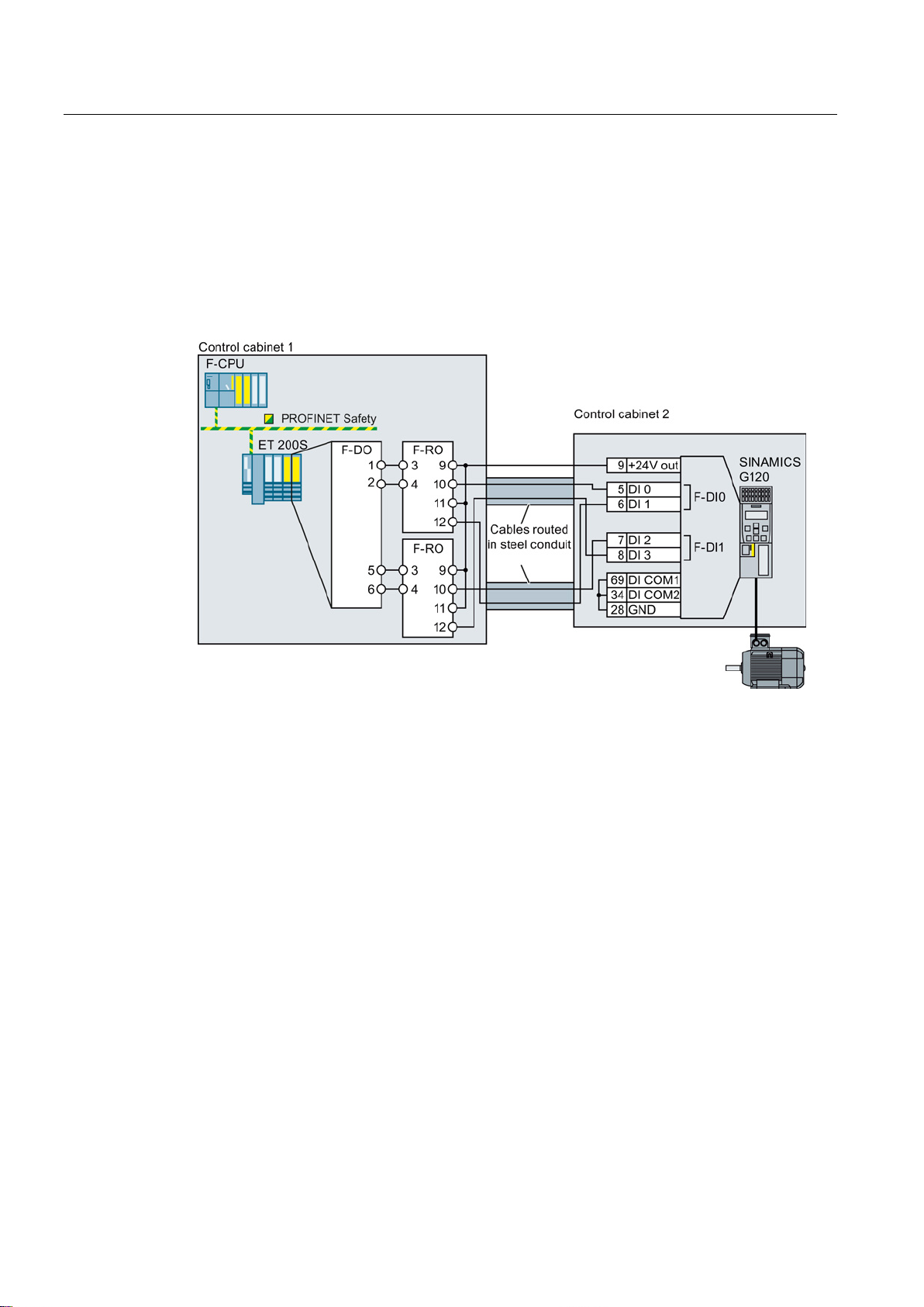
Installing
Components in separate control cabinets
4.3 Activation via F-DI
If the components are located in separate control cabinets, the wiring between the I/O
modules and the F-DIs on the inverter must be installed such that it is protected against
cross and short-circuits.
Transfer the two signals for activating a safety function via wires in separate lines. In the
example, the signals for terminal 5 and 7 are transferred via the first wire. The signals for
terminal 6 and 8 are then transferred via the second wire.
Figure 4-21 Interconnecting the inverter and I/O modules in separate control cabinets
Safety Integrated - SINAMICS G110M, G120, G120C, G120D and SIMATIC ET 200pro FC-2
70 Function Manual, 04/2014, FW V4.7, A5E34261271B AA
Page 71
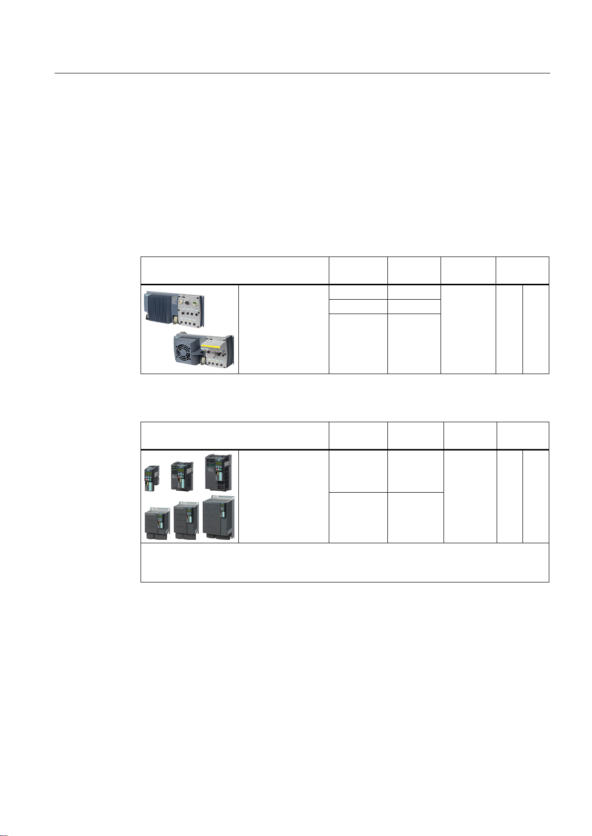
Installing
4.4
Evaluating via F-DO
4.4.1
Safety output
SINAMICS G120D with Control Unit
Connector.
Pin
Digital
output
Safety
output
Read back
input
X5.4
DO 0
X5.2
DO 1
SINAMICS G120 with Control Unit
Terminal
strip
Digital
output
Safety
output
Read back
input
20: COM
inverter. The safe state of the output is always the quiescent state of the two relays.
What devices can be connected?
4.4 Evaluating via F-DO
In the factory setting of the inverter, the safety output is assigned to none of the integrated
safety functions. Only when commissioning do you define whether you use, for example, the
two digital outputs for standard functions, or you combine them to create a safety output.
Table 4- 12 inverters for cabinet-free installation (IP65)
CU240D-2 DP-F
CU240D-2 PN-F
CU240D-2 PN-F PP
CU250D-2 DP-F
CU250D-2 PN-F
CU250D-2 PN-F PP
Table 4- 13 Inverter for installation in a control cabinet (IP20)
CU250S-2
CU250S-2 DP
CU250S-2 PN
CU250S-2 CAN
Most applications require NO contacts for a safety output.
If your application requires it, instead of NO contacts, you can also use the two NC contacts of the
X5.3 2M
18: NC
19: NO
23: NC
24: NO
25: COM
DO 0 F-DO 0 67 DI 6
DO 2
F-DO 0 X9.2 DI 5
The safety output is designed for the following devices:
● Direct connection of a safety input.
● Connection of two relays.
The two signals of the safety output each have the same state:
● High signal or NO contact closed: Safety output is active.
● Low signal or NO contact open: Safety output is not active.
Safety Integrated - SINAMICS G110M, G120, G120C, G120D and SIMATIC ET 200pro FC-2
Function Manual, 04/2014, FW V4.7, A5E34261271B AA
71
Page 72
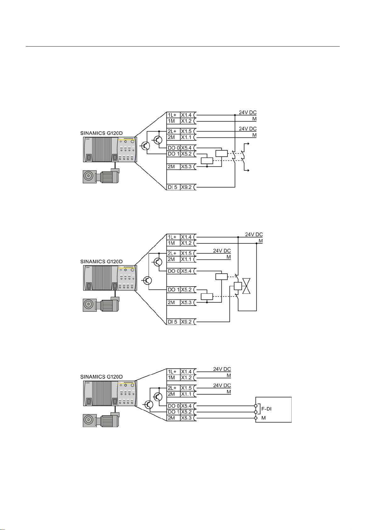
Installing
4.4.2
Connecting the safety output for SINAMICS G120D
Connecting a relay
Connecting an actuator with feedback signal
Connecting a safety input
4.4 Evaluating via F-DO
Figure 4-22 Connecting a relay at the F-DO
Figure 4-23 Connecting an F-DO to an actuator
Figure 4-24 Connecting an F-DO with an F-DI
Safety Integrated - SINAMICS G110M, G120, G120C, G120D and SIMATIC ET 200pro FC-2
72 Function Manual, 04/2014, FW V4.7, A5E34261271B AA
Page 73
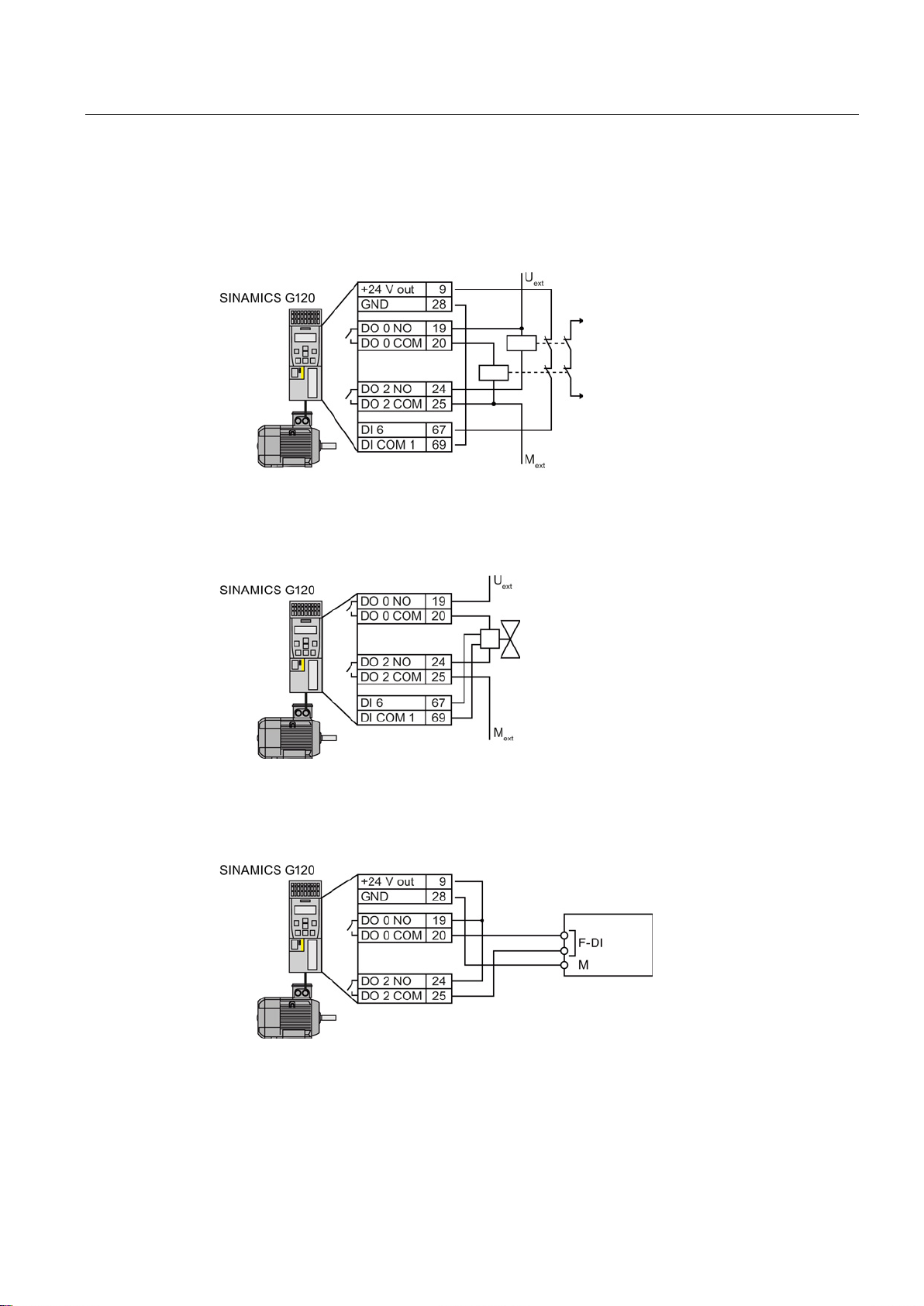
Installing
4.4.3
Connecting the safety output for SINAMICS G120
Connecting a relay
Connecting an actuator with feedback signal
Connecting a safety input
4.4 Evaluating via F-DO
Figure 4-25 Connecting a relay at the F-DO
Figure 4-26 Connecting an F-DO to an actuator
Figure 4-27 Connecting an F-DO with an F-DI
The safety input F-DI must monitor both signals of the safety output for consistency.
Safety Integrated - SINAMICS G110M, G120, G120C, G120D and SIMATIC ET 200pro FC-2
Function Manual, 04/2014, FW V4.7, A5E34261271B AA
73
Page 74
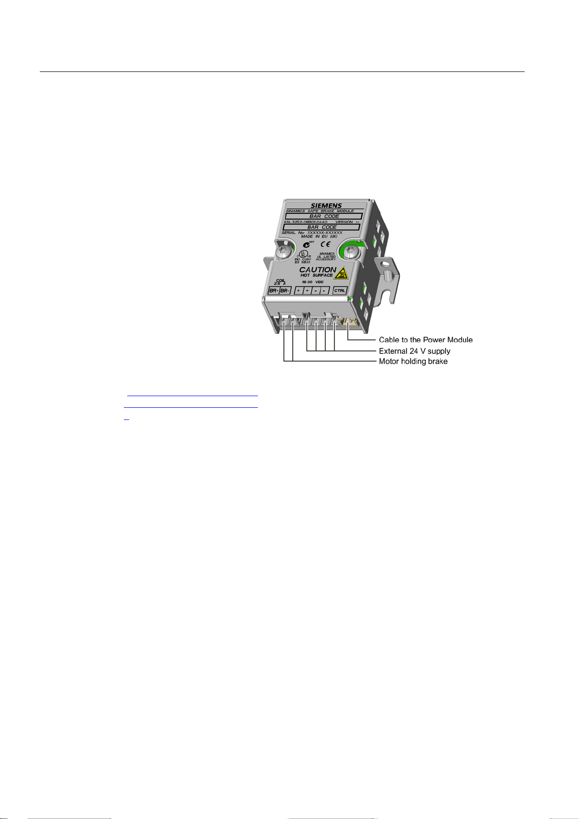
Installing
4.5
Connecting a motor holding brake to a Safe Brake Relay
Connecting a Safe Brake Relay and a motor holding brake
The Safe Brake Relay serves
as an interface between the
Power Module and the motor's
brake coil.
The following options are
available for installing the Safe
Brake Relay:
•
•
•
For additional information,
please refer to the associated
installation instructions:
Installation instructions for the
Brake Relay
(
ens.com/WW/view/en/2362317
9).
Safe Brake Relay connections
4.5 Connecting a motor holding brake to a Safe Brake Relay
On a mounting plate
On the control cabinet wall
On the inverter's shield
connection kit
http://support.automation.siem
Safety Integrated - SINAMICS G110M, G120, G120C, G120D and SIMATIC ET 200pro FC-2
74 Function Manual, 04/2014, FW V4.7, A5E34261271B AA
Page 75
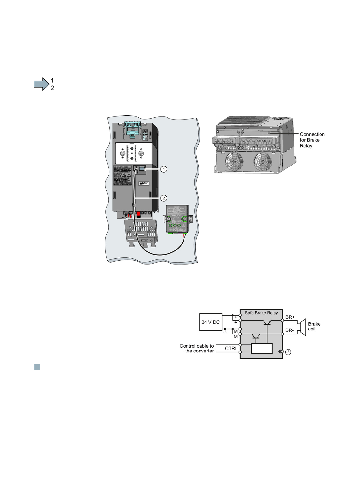
Installing
Procedure
1.
Connect the Safe Brake Relay to the Power Module using the cable harness provided.
Power Modules FSA … FSC:
Power Modules FSD … FSF
•
•
•
2. Connect the motor holding
brake to
Safe Brake Relay:
4.5 Connecting a motor holding brake to a Safe Brake Relay
To interconnect the inverter with the motor holding brake via the Safe Brake Relay, proceed
as follows:
Connect the Safe Brake Relay at the
connector on the lower side of the Power
Module.
Connect the Safe Brake Relay at the
connector on the front of the Power
Module.
Route the control cable in the guide on
the Power Module.
the terminals of the
You have connected the motor holding brake to the inverter via the Safe Brake Relay.
Safety Integrated - SINAMICS G110M, G120, G120C, G120D and SIMATIC ET 200pro FC-2
Function Manual, 04/2014, FW V4.7, A5E34261271B AA
75
Page 76

Installing
4.5 Connecting a motor holding brake to a Safe Brake Relay
Safety Integrated - SINAMICS G110M, G120, G120C, G120D and SIMATIC ET 200pro FC-2
76 Function Manual, 04/2014, FW V4.7, A5E34261271B AA
Page 77
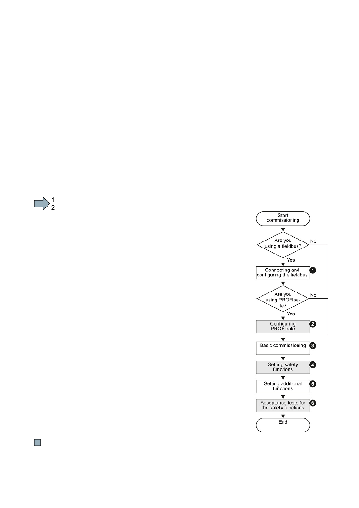
5
5.1
Commissioning guidelines
Procedure
1.
2.
level
3.
4.
5.
6.
The overview below shows the procedure for commissioning an inverter with integrated
safety functions.
The steps for commissioning the safety functions form part of the activities for
commissioning the entire drive.
● The commissioning steps marked in gray are described → in this manual.
● For the other steps, you are supported by → additional manuals.
To commission an inverter with integrated safety functions, proceed as follows:
Connect the fieldbus to the inverter, and configure the
communication in the higher-level control.
→ manual of your control system
→ operating instructions of your inverter
Configure the PROFIsafe communication in the higher-
level control system.
→ in this manual: Configure PROFIsafe in the highercontrol system (Page 78).
Carry out the basic commissioning of the drive.
→ operating instructions of your inverter
Set the inverter safety functions.
→ subsequent pages in this manual
Commission all of the other inverter functions required,
e.g. motor control or the protective functions.
→ operating instructions of your inverter
Perform an acceptance test for the safety functions.
→ in this manual: Acceptance tests for the safety
functions (Page 156)
You have commissioned the inverter with integrated safety functions.
Safety Integrated - SINAMICS G110M, G120, G120C, G120D and SIMATIC ET 200pro FC-2
Function Manual, 04/2014, FW V4.7, A5E34261271B AA
77
Page 78

Commissioning
5.2
Configure PROFIsafe in the higher-level control system
5.2.1
Configuring PROFIBUS communication with telegram 30 via GSD
Procedure
5.2 Configure PROFIsafe in the higher-level control system
You will find the following examples in this chapter:
● Configuring PROFIsafe communication between a higher-level control and an inverter
with a GSD.
● Defining the interface to a SIMATIC control program.
● Configuring shared device communication
You can find additional information as application description or FAQ in the Internet, e.g.
● Configuring a PROFIsafe telegram with Drive ES Basic
(http://support.automation.siemens.com/WW/view/en/64326460)
● Controlling SINAMICS G120 via PROFIsafe, displaying inverter messages on an HMI
(http://support.automation.siemens.com/WW/view/en/61450312)
To configure PROFIsafe communication via PROFIBUS in the higher-level control, proceed
as follows:
1. Configure your SIMATIC CPU (for example, a CPU315F-2 PN/DP ) with a PROFIBUS
network.
2. Integrate the inverter via its GSD into the PROFIBUS network.
3. Assign the first inverter slot to the PROFIsafe telegram.
Safety Integrated - SINAMICS G110M, G120, G120C, G120D and SIMATIC ET 200pro FC-2
78 Function Manual, 04/2014, FW V4.7, A5E34261271B AA
Page 79
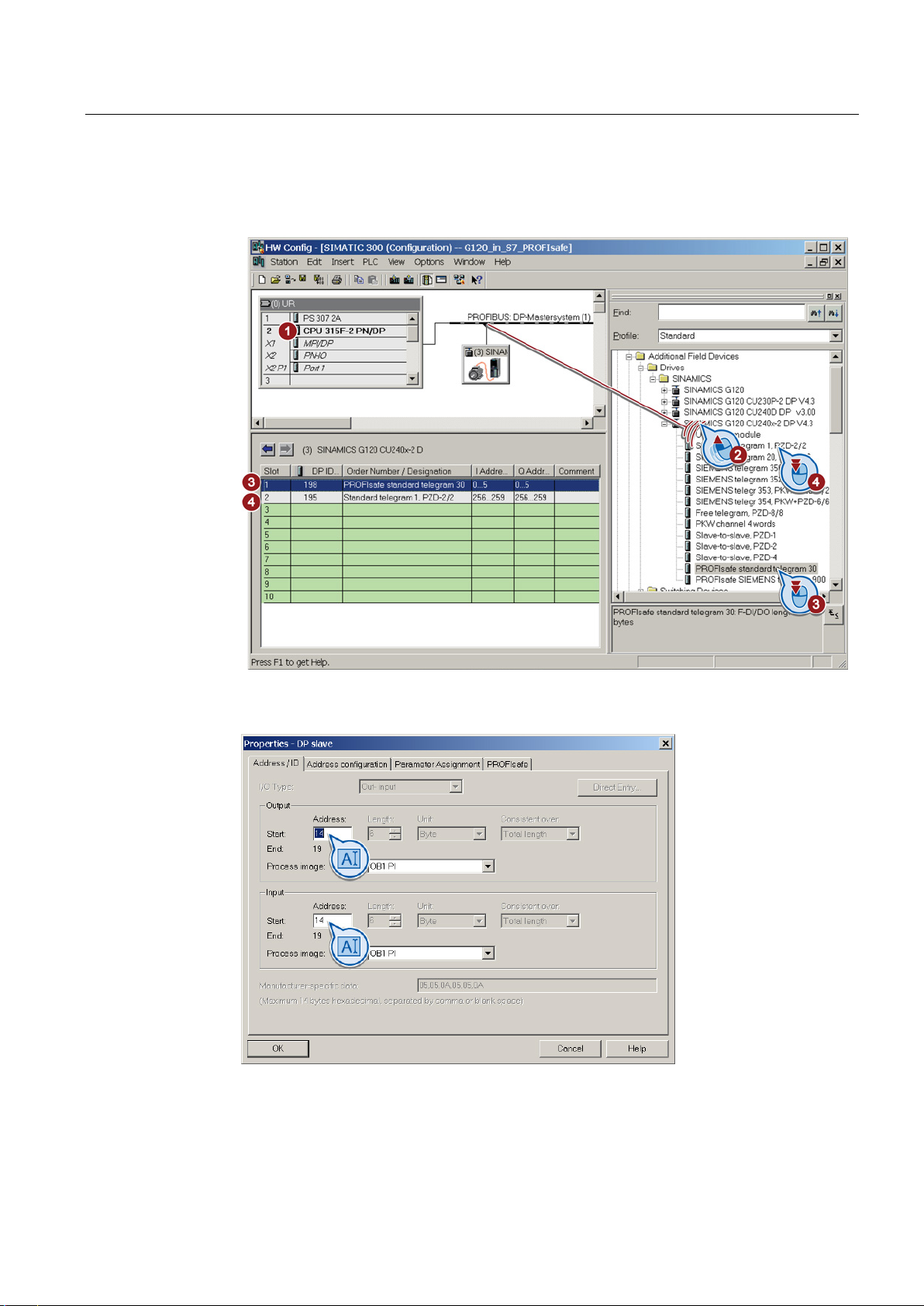
Commissioning
5.2 Configure PROFIsafe in the higher-level control system
4. Assign standard telegram 1, for example, to the other slots of the inverter.
The operating instructions contain further information on the telegrams and slot
sequence.
5. Open the properties dialog by double-clicking on the PROFIsafe telegram.
6. Set the input and output range, e.g. to address 14:
Safety Integrated - SINAMICS G110M, G120, G120C, G120D and SIMATIC ET 200pro FC-2
Function Manual, 04/2014, FW V4.7, A5E34261271B AA
79
Page 80
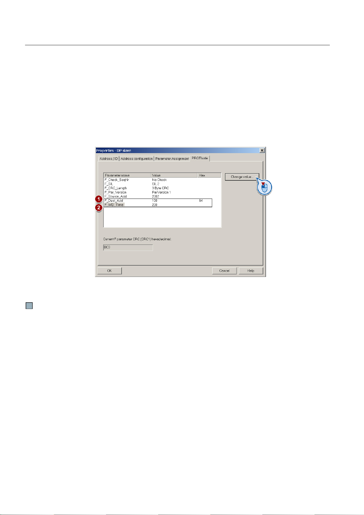
Commissioning
5.2.2
Example: Interface to the S7 safety program
5.2 Configure PROFIsafe in the higher-level control system
7. In this dialog, select the "PROFIsafe" tab.
–
① F_Dest_Add
Note the value of this address. You require this value when commissioning the safety
functions.
–
② F_WD_Time
Set a value which is greater than the cycle time of your safety program.
If your safety program is called every 150 ms, for example, in OB35, set the value of
F_WD_Time to 200.
8. Save and compile your project and download the data to your SIMATIC CPU.
9. Close HW Config.
You have configured the PROFIsafe communication in the higher-level control system.
When you configure the hardware in STEP 7, you assign the control word and status word in
the PROFIsafe profile of the inverter to specific output and input addresses of the SIMATIC
controller. In section Configuring PROFIBUS communication with telegram 30 via GSD
(Page 78), start address 14, for example, was assigned. This results in the following
assignments between the I/O addresses and inverter signals for this example:
Safety Integrated - SINAMICS G110M, G120, G120C, G120D and SIMATIC ET 200pro FC-2
80 Function Manual, 04/2014, FW V4.7, A5E34261271B AA
Page 81

Commissioning
I/O address
Meaning
Comment
0
Select STO
1
Deselect STO
0
Select SS1
1
Deselect SS1
0
Select SLS
1
Deselect SLS
A14.7
Internal event ACK
-
Acknowledge with signal change 1 → 0
A15.1
Select SLS level bit 0
-
A15.2
Select SLS level, bit 1
-
0
Select SDI positive
1
Deselect SDI positive
0
Select SDI negative
1
Deselect SDI negative
I/O address
Meaning
Comment
safely.
1
The motor torque has been switched off safely.
0
SS1 is not active
0
SLS is not active
0
Fault-free operation
responded accordingly, e.g. with a STOP A.
E15.1
Active SLS level, bit 0
-
E15.2
Active SLS level, bit 1
-
0
SDI positive direction of rotation is not active
1
SDI positive direction of rotation is active
0
SDI negative direction of rotation is not active
1
SDI negative direction of rotation is active
SSM limit value
limit value
5.2 Configure PROFIsafe in the higher-level control system
Table 5- 1 Control word 1
A14.0 Select STO
A14.1 Select SS1
A14.4 Select SLS
Selection of the SLS level
A15.4 Select SDI positive
A15.5 Select SDI negative
Table 5- 2 Status word 1
E14.0 Power removed 0 The motor torque has not yet been switched off
E14.1 SS1 active
1 SS1 is active
E14.4 SLS active
1 SLS is active
E14.7 Internal event
1 The inverter has detected an internal fault and
Active SLS level
E15.4 SDI positive active
E15.5 SDI negative active
E15.7 Status SSM 0 Absolute value of the speed is greater than the
1 Absolute value of the speed is less than the SSM
You will find additional information on the PROFIsafe interface in Section Control word 1 and
status word 1 (extended functions) (Page 48).
Safety Integrated - SINAMICS G110M, G120, G120C, G120D and SIMATIC ET 200pro FC-2
Function Manual, 04/2014, FW V4.7, A5E34261271B AA
81
Page 82
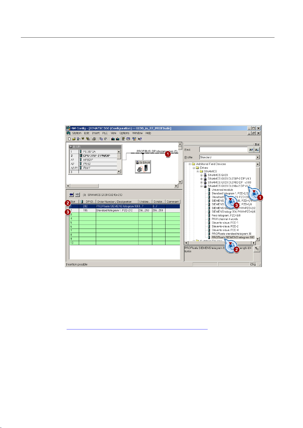
Commissioning
5.2.3
Configuring PROFIBUS communication via telegram 900 with the GSDML
Hardware configuration
5.2.4
Configuring shared device communication via PROFINET
5.2 Configure PROFIsafe in the higher-level control system
If you want to evaluate the status of the safety inputs in the higher-level control directly,
choose PROFIsafe telegram 900. The inverter writes the signals of its safety inputs to status
word 5.
The basic procedure is described in the section Configuring PROFIBUS communication with
telegram 30 via GSD (Page 78). Instead of telegram 30, select telegram 900:
Safety Integrated - SINAMICS G110M, G120, G120C, G120D and SIMATIC ET 200pro FC-2
82 Function Manual, 04/2014, FW V4.7, A5E34261271B AA
In the following example, the standard CPU and the F-CPU are combined in a single project.
The communication via the Shared Device is also possible, even if both controls are
configured in different projects.
Firmware required: see also Support of the IO controller
(http://support.automation.siemens.com/WW/view/en/44383955).
Page 83
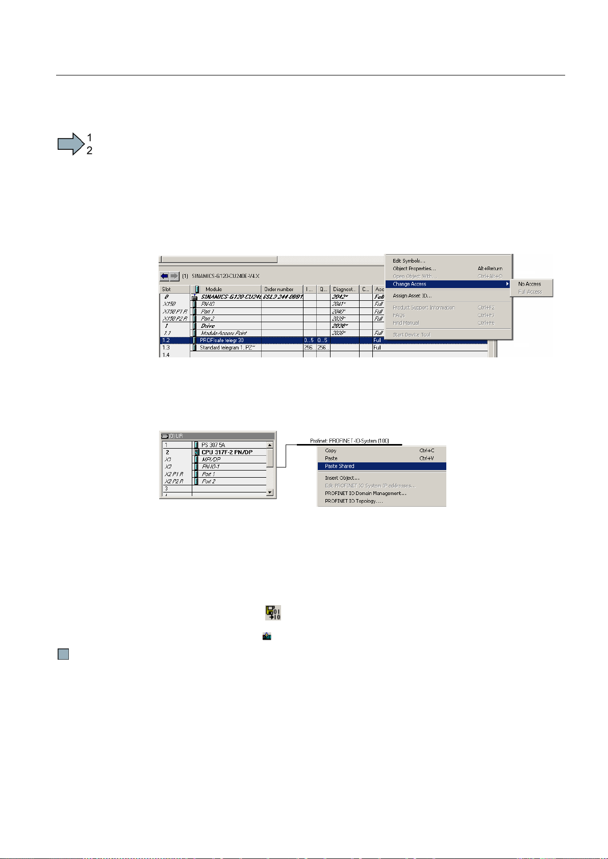
Commissioning
Procedure
5.2 Configure PROFIsafe in the higher-level control system
To configure communication via "Shared Device" in the higher-level control, proceed as
follows:
1. Configuring your system with the standard control.
2. In HW Config, in addition to the protocol for the standard functions (for example: telegram
1), insert your communications protocol for the fail-safe functions (e.g. PROFIsafe
telegram 30).
3. Deactivate the access to the PROFIsafe telegram via the context menu of the right
mouse button:
4. You can configure your F-CPU in HW Config, without inserting an inverter.
5. Copy the inverter into the standard control
6. Insert the inverter as "Shared" in the F-CPU.
This results in the access rights being "reversed".
7. Select the F-CPU in HW Config
8. Open the "Object Properties" dialog window.
9. In this window, select the "Protection" tab.
10.Activate the access protection for F-CPU and assign a password.
11.Check the box for "CPU contains safety program" and exit the screen with OK.
12.Save and compile your
13.Load your project via
project.
into the fail-safe control.
You have configured the communication via "Shared Device" in the higher-level control
system.
Safety Integrated - SINAMICS G110M, G120, G120C, G120D and SIMATIC ET 200pro FC-2
Function Manual, 04/2014, FW V4.7, A5E34261271B AA
83
Page 84
Commissioning
5.3
Commissioning tools
Tool
Can be downloaded at no
charge
Order number
ns.com/WW/view/en/26233208)
ns.com/WW/view/en/68034568)
Commissioning: Online or offline
5.3 Commissioning tools
We strongly recommend that you commission the safety functions using a PC tool.
If you use a PC tool for commissioning, then you set the functions using the graphic screen
forms and you do not have to work with parameters. In this case, you can ignore the
parameter tables in the following sections.
Table 5- 3 PC-based commissioning tools
STARTER STARTER
Startdrive Startdrive
Commissioning the safety functions with STARTER is subsequently described.
A tutorial is available for Startdrive: Startdrive tutorial
(http://support.automation.siemens.com/WW/view/en/73598459).
With STARTER, you can work offline (without a connection to the converter) as well as
online. We recommend that you commission the safety functions online.
This manual provides a detailed description of the online commissioning procedure. The
section Offline commissioning (Page 153) describes the important points to remember when
commissioning the safety functions offline.
Additional information about STARTER is provided in the operating instructions of your
converter.
6SL3072-0AA00-0AG0
(http://support.automation.sieme
6SL3072-4CA02-1XG0
(http://support.automation.sieme
Safety Integrated - SINAMICS G110M, G120, G120C, G120D and SIMATIC ET 200pro FC-2
84 Function Manual, 04/2014, FW V4.7, A5E34261271B AA
Page 85
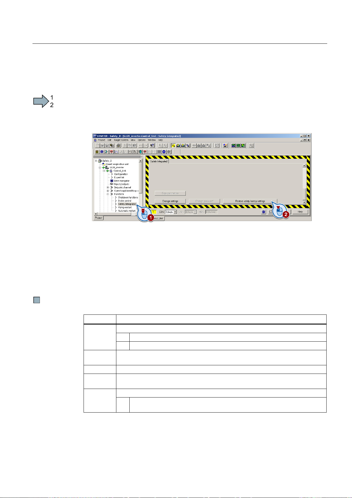
Commissioning
5.4
Resetting the safety function parameters to the factory setting
Procedure
Parameters
Description
Drive, commissioning parameter filter
0
Ready
30
Parameter reset
Enter a password
Permissible passwords lie in the range 1 … FFFF FFFF.
New password
Password confirmation
Confirming the new Safety Integrated password.
Reset drive parameters
After the reset, the inverter sets p0970 = 0.
5.4 Resetting the safety function parameters to the factory setting
To reset the safety function settings to the factory setting without changing the standard
settings, proceed as follows:
1. Go online with STARTER
2. Open the screen form for the safety functions
①.
3. Press the button to restore the factory settings
②.
4. Enter the password,for the safety functions.
5. Confirm saving parameters (RAM to ROM).
6. Go offline with STARTER .
7. Switch off the inverter supply voltage.
8. Wait until all LED on the inverter go dark. Now switch on the inverter supply voltage again
(power on reset).
You have restored the safety functions in the inverter to the factory settings.
p0010
p9761
p9762
p9763
p0970
(factory setting: 0000 hex)
5 Starts a safety parameter reset.
Safety Integrated - SINAMICS G110M, G120, G120C, G120D and SIMATIC ET 200pro FC-2
Function Manual, 04/2014, FW V4.7, A5E34261271B AA
85
Page 86
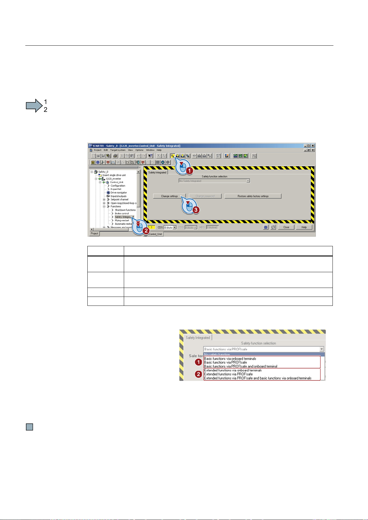
Commissioning
5.5
Changing settings
Procedure
Parameter
Description
Drive commissioning parameter filter
Safety Integrated commissioning
Enter a password
p9762
New password
p9763
Confirm password
4.
Define what the results of your commissioning should look like:
•
with the interface that matches
• If, in addition to STO you use other safety functions, then select the extended functions
Additional information on the basic and extended functions are
pages of this section.
5.5 Changing settings
To start commissioning the safety functions, proceed as follows:
1. Go online with STARTER
2. In STARTER, select the fail-safe functions.
3. Select "Change settings".
p0010 = 95
p9761
(factory setting: 0000 hex)
Permissible passwords lie in the range 1 … FFFF FFFF.
If you are only using STO as
safety function of the inverter,
select the basic functions
①
your particular application.
② with the interface that matches your particular application.
provided on the following
You have completed the following commissioning steps:
● You have started to commission the safety functions.
● You have decided to use either the basic functions or the extended functions.
Safety Integrated - SINAMICS G110M, G120, G120C, G120D and SIMATIC ET 200pro FC-2
86 Function Manual, 04/2014, FW V4.7, A5E34261271B AA
Page 87

Commissioning
Parameter
Description
Enable functions integrated in the drive (factory setting: 0000 bin)
0 hex
Safety functions integrated in the drive inhibited
1 hex
Basic function STO via onboard terminals is enabled
4 hex
Extended Functions via onboard terminals are enabled
8 hex
Basic function STO is enabled via PROFIsafe
9 hex
Basic function STO is enabled via PROFIsafe and onboard terminals
C hex
Extended functions are enabled via PROFIsafe
onboard terminal
5.5 Changing settings
p9601
D hex Extended functions are enabled via PROFIsafe and basic function STO via
Safety Integrated - SINAMICS G110M, G120, G120C, G120D and SIMATIC ET 200pro FC-2
Function Manual, 04/2014, FW V4.7, A5E34261271B AA
87
Page 88
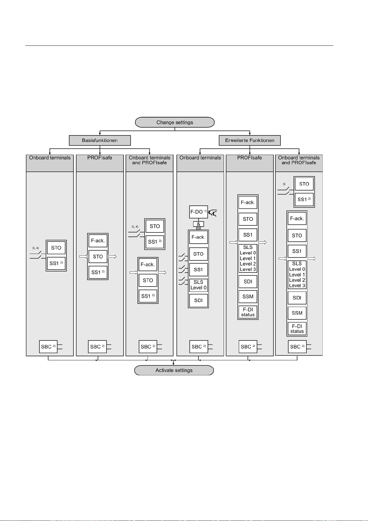
Commissioning
Overview of the safety functions
5.5 Changing settings
When starting to commission the system, you already define the following:
● Which safety functions are available?
● Which interfaces are used to control the safety functions?
1
Not all of the Control Units have a safety output, also refer to Section: Overview of the
safety-related inverter interfaces (Page 21).
2)
The basic SS1 functions and the SBC function are only available with the CU250S-2
Control Unit, also see Section:Overview of the safety functions (Page 19)
3)
Controlling the basic functions for SINAMICS G inverters via F-DI 0, also see Section:
Safety inputs (Page 51).
4)
Controlling the basic functions for SIMATIC ET 200pro FC-2 via the F0 rail.
Safety Integrated - SINAMICS G110M, G120, G120C, G120D and SIMATIC ET 200pro FC-2
88 Function Manual, 04/2014, FW V4.7, A5E34261271B AA
Page 89

Commissioning
Your selection
Outcome of commissioning
See section ...
5.5 Changing settings
Basic functions
via onboard
terminals
Basic functions
via PROFIsafe
Basic functions
via PROFIsafe
and onboard
terminals
Extended
functions via
onboard terminals
Extended
functions via
PROFIsafe
Extended
functions via
PROFIsafe and
basic functions
via onboard
terminals
• Select STO via F-DI.
• Acknowledge safety function faults after selecting and deselecting STO.
Additionally, with CU250S-2:
• Select SS1 via F-DI.
• Control the motor holding brake via SBC.
• Select STO via PROFIsafe.
• Evaluate state of STO via PROFIsafe.
• Acknowledge safety function faults via PROFIsafe.
Additionally, with CU250S-2:
• Select SS1 via PROFIsafe.
• Control the motor holding brake via SBC.
• Select STO via F-DI as well as also via PROFIsafe.
• Evaluate state of STO via PROFIsafe.
• Acknowledge safety function faults:
– via PROFIsafe
– after selecting and deselecting STO
Additionally, with CU250S-2:
• Select SS1 via F-DI or PROFIsafe.
• Control the motor holding brake via SBC.
• Select safety functions via F-DI.
• Only one monitoring limit of SLS can be used (SLS level 0).
• Acknowledge safety function faults:
– via F-DI
– after selecting and deselecting STO
• Select safety functions via PROFIsafe.
• Evaluate the state of the safety functions via PROFIsafe.
• All four monitoring limits of SLS can be used (SLS levels 0 … 3)
• Acknowledge safety function faults via PROFIsafe.
• Evaluate the state of the safety inputs via PROFIsafe.
• Select safety functions via PROFIsafe.
• Additionally select STO via F-DI.
• Evaluate the state of the safety functions via PROFIsafe.
• All four monitoring limits of SLS can be used (SLS levels 0 … 3)
• Acknowledge safety function faults:
– via F-DI
– after selecting and deselecting STO
• Evaluate the state of the safety inputs via PROFIsafe.
Additionally, with CU250S-2:
• Additionally select SS1 via F-DI.
• Control the motor holding brake via SBC.
Setting basic
functions
(Page 90).
Setting extended
functions
(Page 103).
Safety Integrated - SINAMICS G110M, G120, G120C, G120D and SIMATIC ET 200pro FC-2
Function Manual, 04/2014, FW V4.7, A5E34261271B AA
89
Page 90
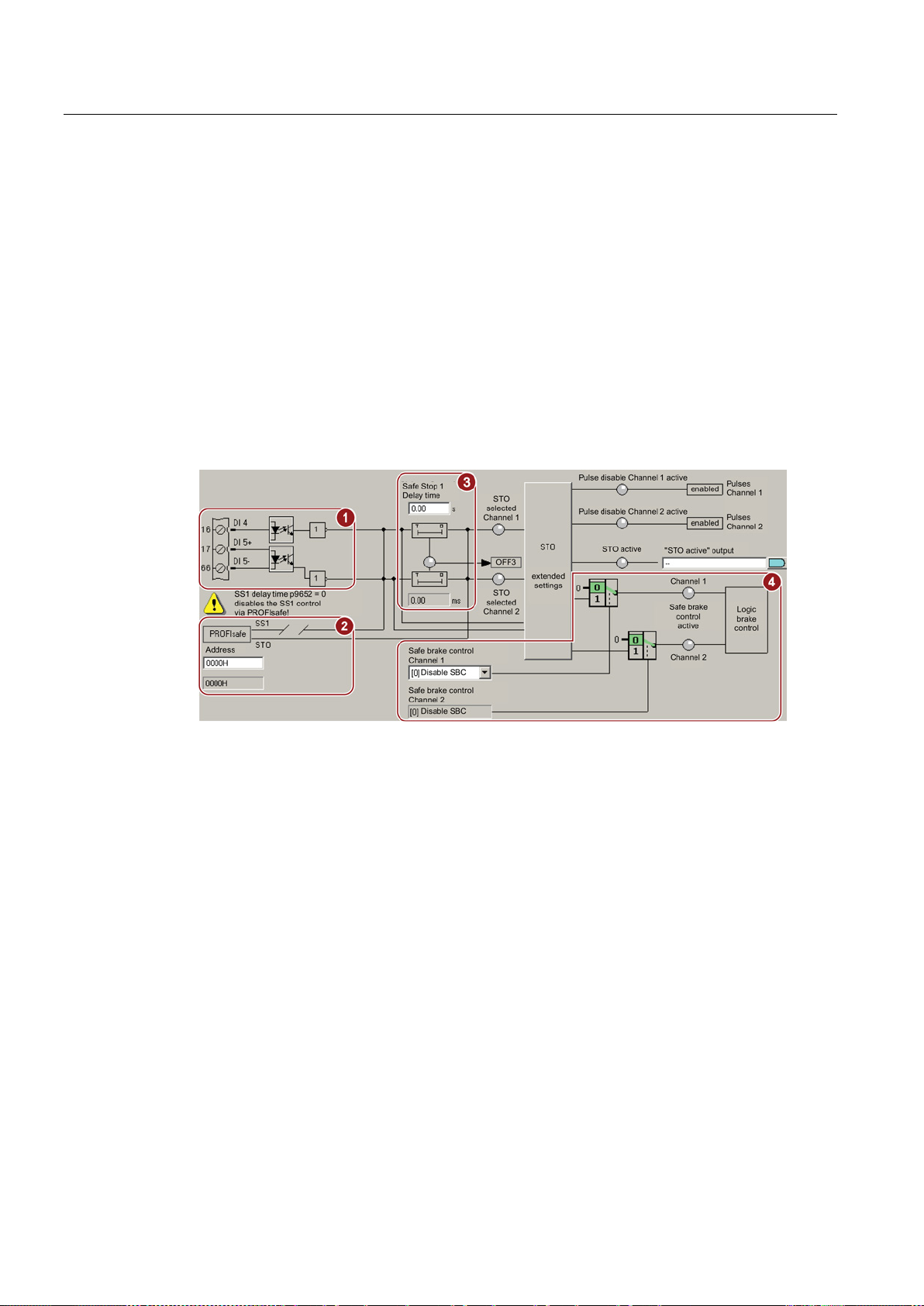
Commissioning
5.6
Setting basic functions
STARTER screen form for the basic functions
5.6 Setting basic functions
Depending on the interface that has been selected, one of the following versions is displayed
on the STARTER screen form of the basic functions:
●
① The onboard terminals for SINAMICS inverters or the F0 rail for
SIMATIC ET 200pro FC.
●
② The PROFIsafe interface
●
① + ② Onboard terminals as well as the PROFIsafe interface
●
③ + ④ if you have an inverter equipped with the CU250S-2 Control Unit, the delay time
for SS1 and the enable for SBC are visible.
Safety Integrated - SINAMICS G110M, G120, G120C, G120D and SIMATIC ET 200pro FC-2
90 Function Manual, 04/2014, FW V4.7, A5E34261271B AA
Page 91
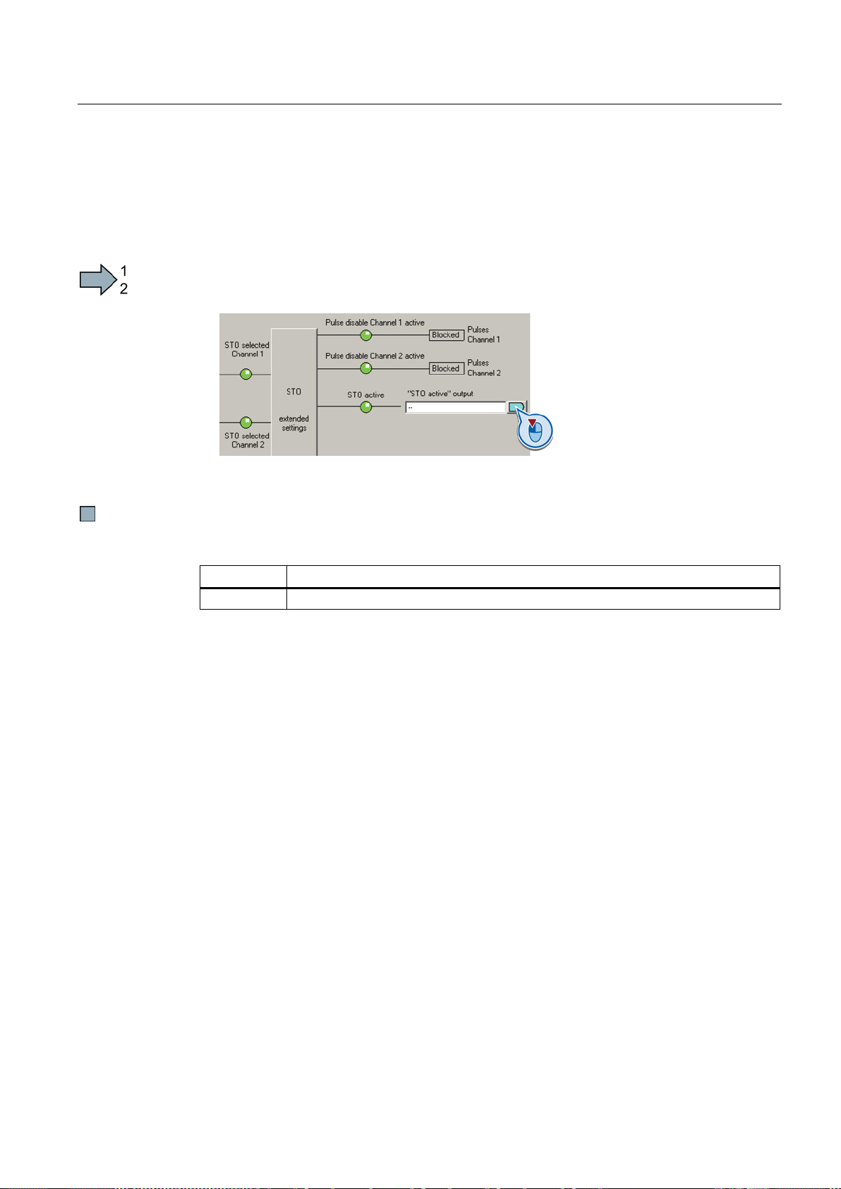
Commissioning
5.6.1
Interconnecting the "STO active" signal
Procedure
Parameter
Description
r9773.01
1 signal: STO is active in the drive
5.6 Setting basic functions
If you require the feedback signal "STO active" of the inverter in your higher-level control
system, then you must appropriately interconnect the signal.
To interconnect the "STO active" checkback signal, proceed as follows:
1. Select the button for the feedback signal.
2. In the following selection menu, select the appropriate setting for your particular
application.
You have interconnected the "STO active" checkback signal. The inverter signals "STO
active" to the higher-level control after STO has been selected.
Safety Integrated - SINAMICS G110M, G120, G120C, G120D and SIMATIC ET 200pro FC-2
Function Manual, 04/2014, FW V4.7, A5E34261271B AA
91
Page 92
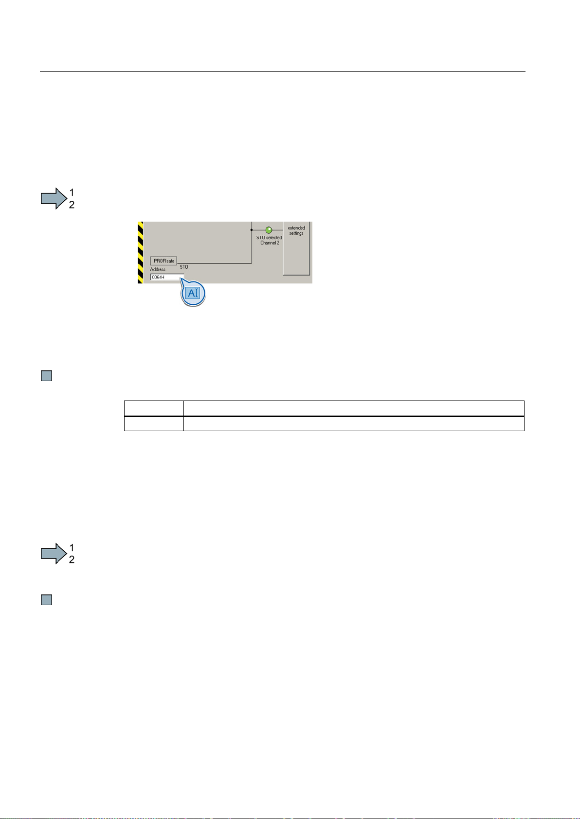
Commissioning
5.6.2
Configuring PROFIsafe
Setting the address
Procedure
Parameter
Description
p9610
PROFIsafe address (factory setting: 0000 hex)
Enabling Shared Device
Procedure
5.6 Setting basic functions
To set the PROFIsafe address, proceed as follows:
1. In STARTER select the input field for the PROFIsafe address
2. Enter the same address as hexadecimal value, which you defined in the hardware
configuration (F_Dest_Add).
See also Section: Configuring PROFIBUS communication with telegram 30 via GSD
(Page 78).
You have configured the communication between the inverter and the higher-level control (FCPU) using PROFIsafe telegram 30.
If you control the inverter safety functions via PROFINET and "Shared Device", you must
enable this function in the inverter.
See also Section: Configuring shared device communication via PROFINET (Page 82).
To configure communication via "Shared Device" in the inverter, proceed as follows:
1. In STARTER change to the expert list.
2. In STARTER, set p8929 = 2.
You have configured the communication via "Shared Device" in the inverter.
Safety Integrated - SINAMICS G110M, G120, G120C, G120D and SIMATIC ET 200pro FC-2
92 Function Manual, 04/2014, FW V4.7, A5E34261271B AA
Page 93

Commissioning
Starting communication via PROFIsafe
5.6 Setting basic functions
When you connect the converter to the higher-level control system (F-CPU) via the fieldbus
for the first time, the central control system sends the PROFIsafe configuration to the
converter. After the configuration data have been received in the converter,
PROFIsafecommunication starts.
The converter only monitors the communication to the F-CPU after the configuration data
have been received from the central control system.
Safety Integrated - SINAMICS G110M, G120, G120C, G120D and SIMATIC ET 200pro FC-2
Function Manual, 04/2014, FW V4.7, A5E34261271B AA
93
Page 94
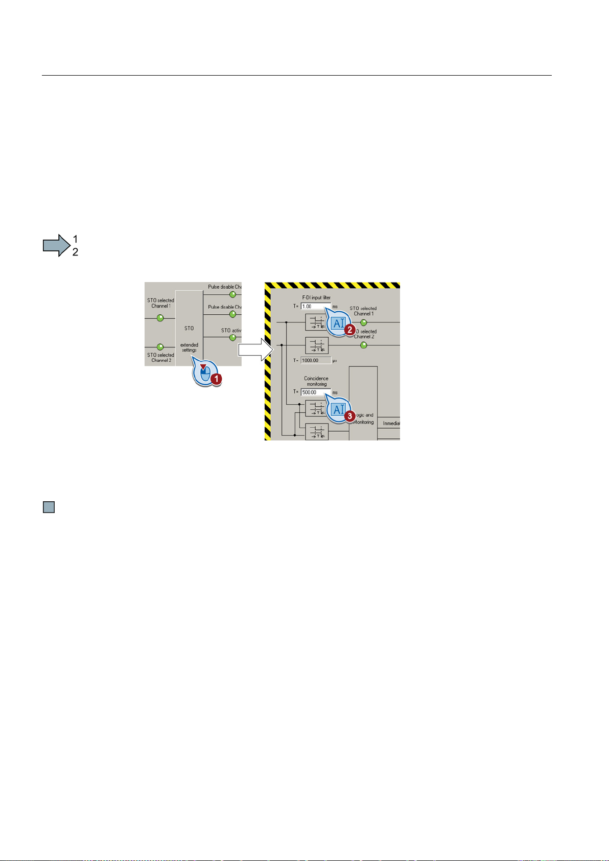
Commissioning
5.6.3
Setting the filter for safety inputs
Procedure
Description of the signal filter
A tolerance for the simultaneous monitoring
5.6 Setting basic functions
You must set the input filter and the simultaneity monitoring of the safety input for all
SINAMICS inverters where the safety F-DI input evaluates two redundant signals.
For SIMATIC ET 200pro FC, the input signal for STO is received from the F0 rail of the
backplane bus of the ET-200pro system. As a consequence, the simultaneity monitoring is
not applicable for this converter.
To set the input filter and simultaneity monitoring of the safety-related input, proceed as
follows:
1. Select the advanced settings for STO.
2. Set the debounce time for the F-DI input filter.
3. Set the discrepancy for the simultaneity monitoring.
4. Close the screen form.
You have set the input filter and the simultaneity monitoring of the safety-related input.
The following are available for the signal processing of the safety-related inputs:
● A tolerance for the simultaneous monitoring.
● A filter to suppress short signals, e.g. test pulses.
The inverter checks whether the signals at both inputs always have the same signal status
(high or low).
With electromechanical sensors (e.g. emergency stop buttons or door switches), the two
sensor contacts never switch at exactly the same time and are therefore temporarily
inconsistent (discrepancy). A long-term discrepancy indicates a fault in the wiring of a safetyrelated input, e.g. a wire break.
When appropriately set, the inverter tolerates brief discrepancies.
Safety Integrated - SINAMICS G110M, G120, G120C, G120D and SIMATIC ET 200pro FC-2
94 Function Manual, 04/2014, FW V4.7, A5E34261271B AA
Page 95
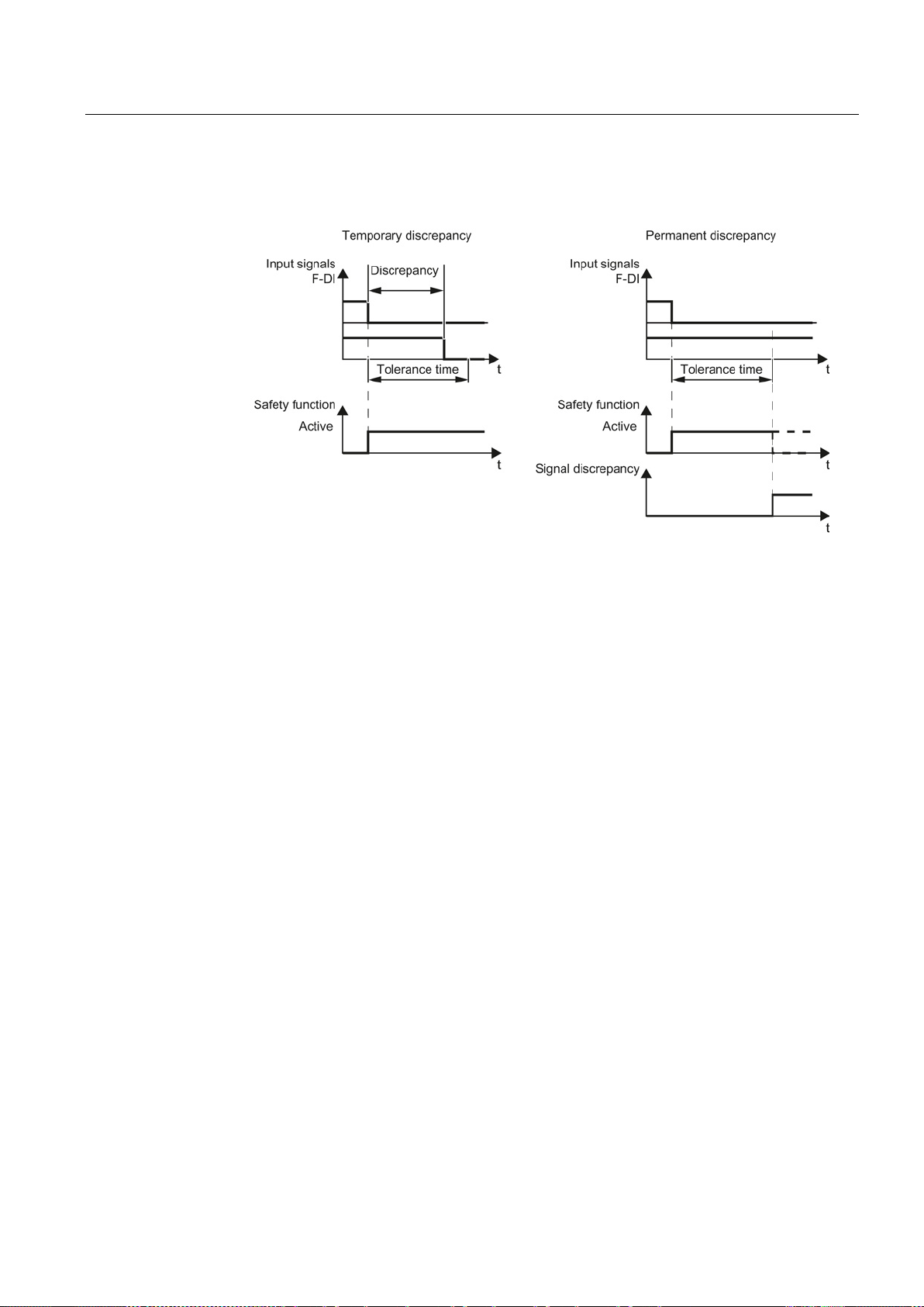
Commissioning
Filter to suppress short signals
5.6 Setting basic functions
The tolerance time does not extend the inverter response time. The inverter selects its safety
function as soon as one of the two F-DI signals changes its state from high to low.
Figure 5-1 Tolerance regarding discrepancy
The inverter normally responds immediately to signal changes at its safety-related inputs.
This is not required in the following cases:
● When you interconnect a safety-related input of the inverter with an electromechanical
sensor, contact bounce may result in signal changes occurring, to which the inverter
responds.
● Several control modules test their safety-related outputs using bit pattern tests
(light/darkness tests) to identify faults due to either short-circuiting or cross circuiting.
When you interconnect a safety-related input of the inverter with a safety-related output of
a control module, the inverter responds to these test signals.
A signal change during a bit pattern test usually lasts:
– On test: 1 ms
– Off test: 4 ms
If the safety-related input signals too many signal changes within a certain time, then the
inverter responds with a fault.
Safety Integrated - SINAMICS G110M, G120, G120C, G120D and SIMATIC ET 200pro FC-2
Function Manual, 04/2014, FW V4.7, A5E34261271B AA
95
Page 96
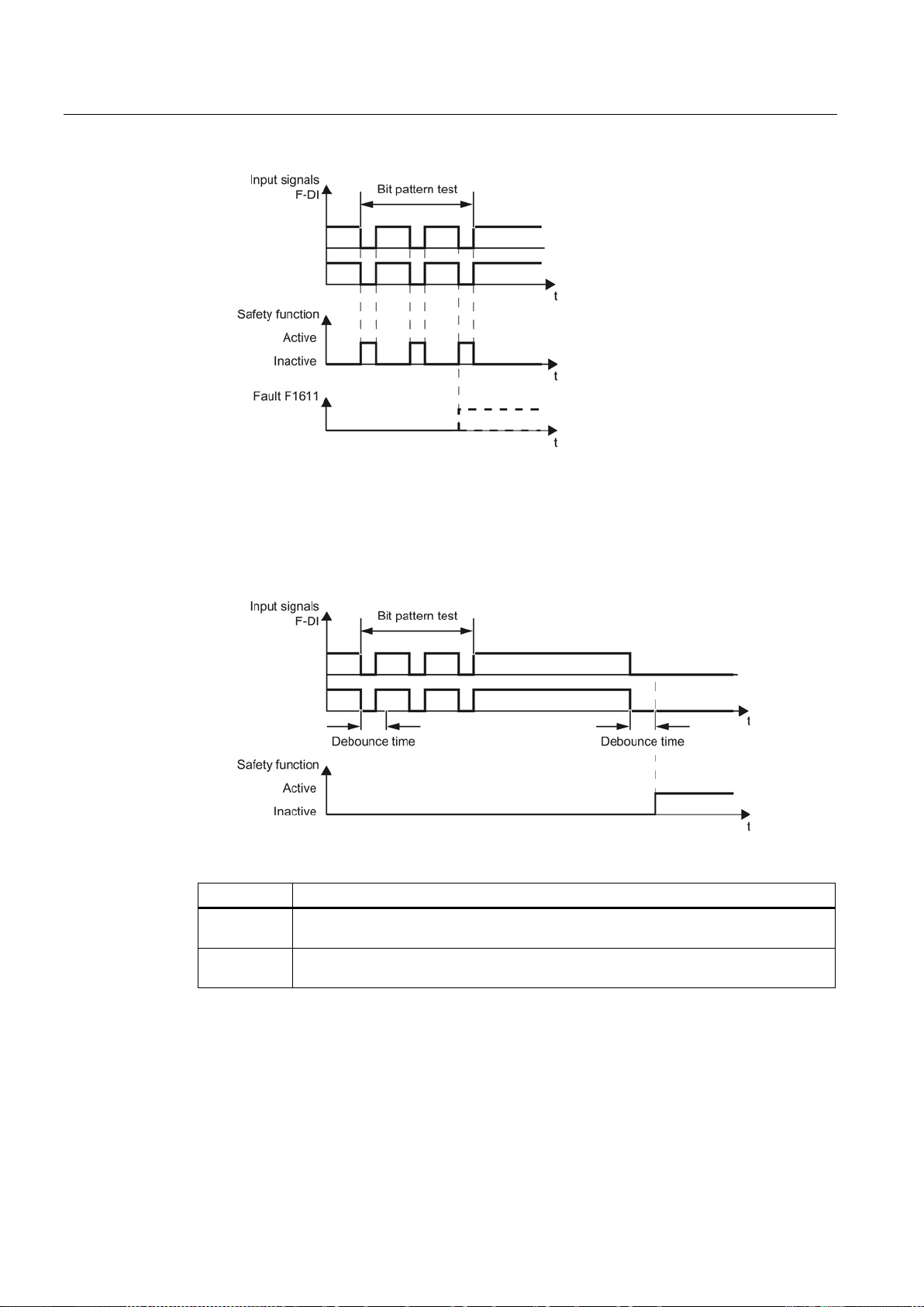
Commissioning
Parameter
Description
F-DI switchover discrepancy time
Tolerance time to switch over the safety input for the basic functions.
STO debounce time
Debounce time of the safety input for the basic functions.
5.6 Setting basic functions
Figure 5-2 Inverter response to a bit pattern test
An adjustable signal filter in the inverter suppresses temporary signal changes using bit
pattern test or contact bounce.
The filter increases the inverter response time. The inverter only selects its safety function
after the debounce time has elapsed.
Figure 5-3 Filter for suppressing temporary signal changes
1)
p9650
p9651
1)
Safety Integrated - SINAMICS G110M, G120, G120C, G120D and SIMATIC ET 200pro FC-2
(factory setting: 1 ms)
(factory setting: 500 ms)
For SIMATIC ET 200pro FC, the tolerance time is always 0 ms.
96 Function Manual, 04/2014, FW V4.7, A5E34261271B AA
Page 97

Commissioning
Debounce times for standard and safety functions
5.6 Setting basic functions
The debounce time p0724 for "standard" digital inputs does not influence the safety input
signals. Conversely, the same applies: The F-DI debounce time does not affect the signals
of the "standard" inputs.
If you use an input as a standard input, set the debounce time using parameter p0724.
If you use an input as a safety input, set the debounce time as described above.
Safety Integrated - SINAMICS G110M, G120, G120C, G120D and SIMATIC ET 200pro FC-2
Function Manual, 04/2014, FW V4.7, A5E34261271B AA
97
Page 98
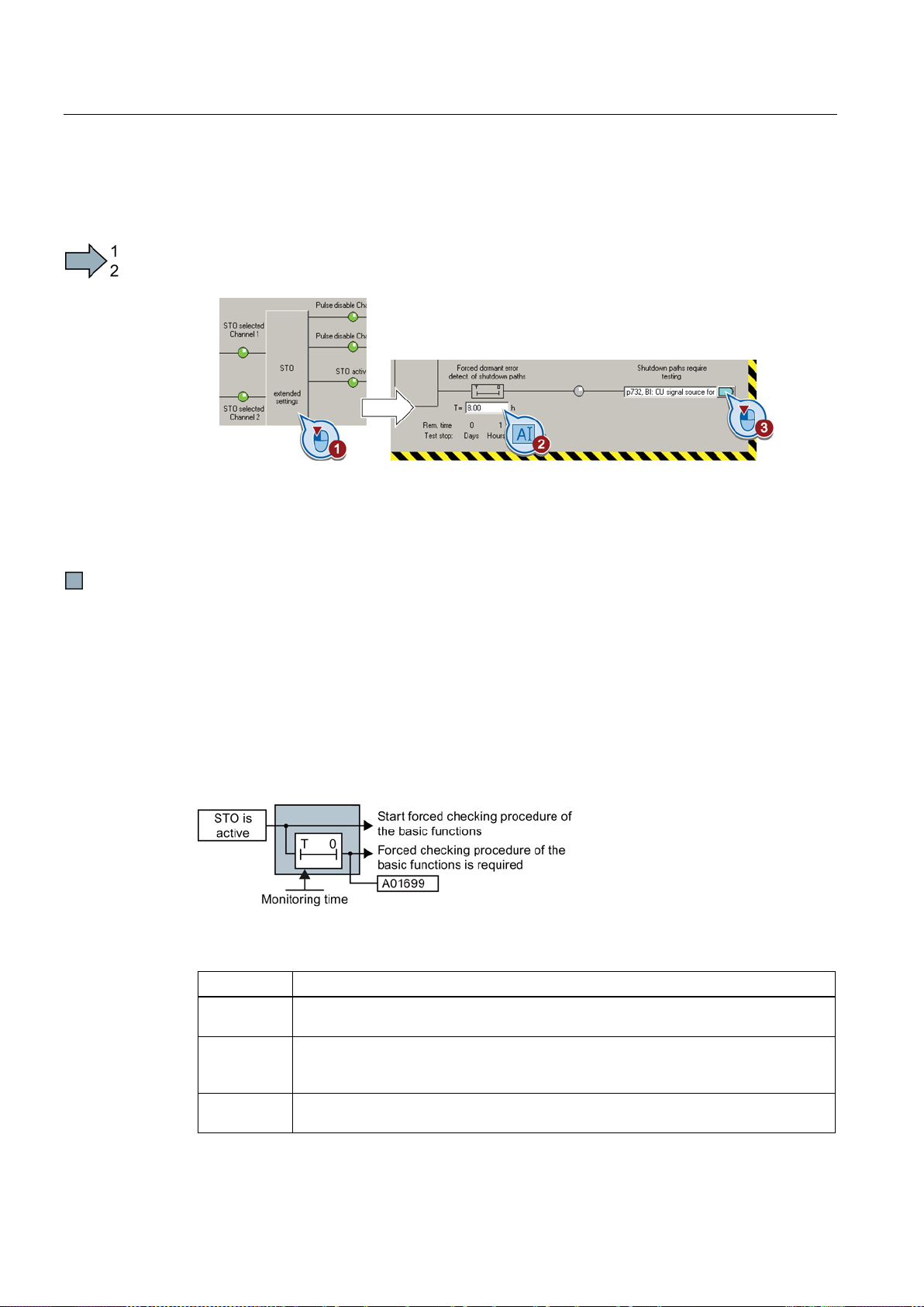
Commissioning
5.6.4
Setting the forced checking procedure (test stop)
Procedure
Description
Parameter
Description
Forced dormant error detection timer
Monitoring time for the forced dormant error detection.
Forced dormant error detection remaining time
safety switch-off signal paths.
1 signal: Forced dormant error detection is required
Signals for the higher-level control system.
5.6 Setting basic functions
To set the forced checking procedure (test stop) of the basic functions, proceed as follows:
1. Select the advanced settings for STO.
2. Set the monitoring time to a value to match your application.
3. Using this signal, the inverter signals that a forced checking procedure (test stop) is
required.
Interconnect this signal with an inverter signal of your choice.
You have set the forced checking procedure (test stop) for the basic functions.
The forced checking procedure (test stop) of the basic functions is an inverter self test. The
inverter checks its circuits to switch off the torque. If you are using the Safe Brake Relay, for
a forced checking procedure, the inverter also checks the circuits of this component.
You start the forced checking procedure each time that the STO function is selected.
Using a timer block, the inverter monitors as to whether the forced checking procedure is
regularly performed.
Figure 5-4 Starting and monitoring the forced checking procedure (test stop)
p9659
r9660
Displays the remaining time until the forced dormant error detection and testing the
r9773.31
Safety Integrated - SINAMICS G110M, G120, G120C, G120D and SIMATIC ET 200pro FC-2
98 Function Manual, 04/2014, FW V4.7, A5E34261271B AA
(Factory setting: 8 h)
Page 99
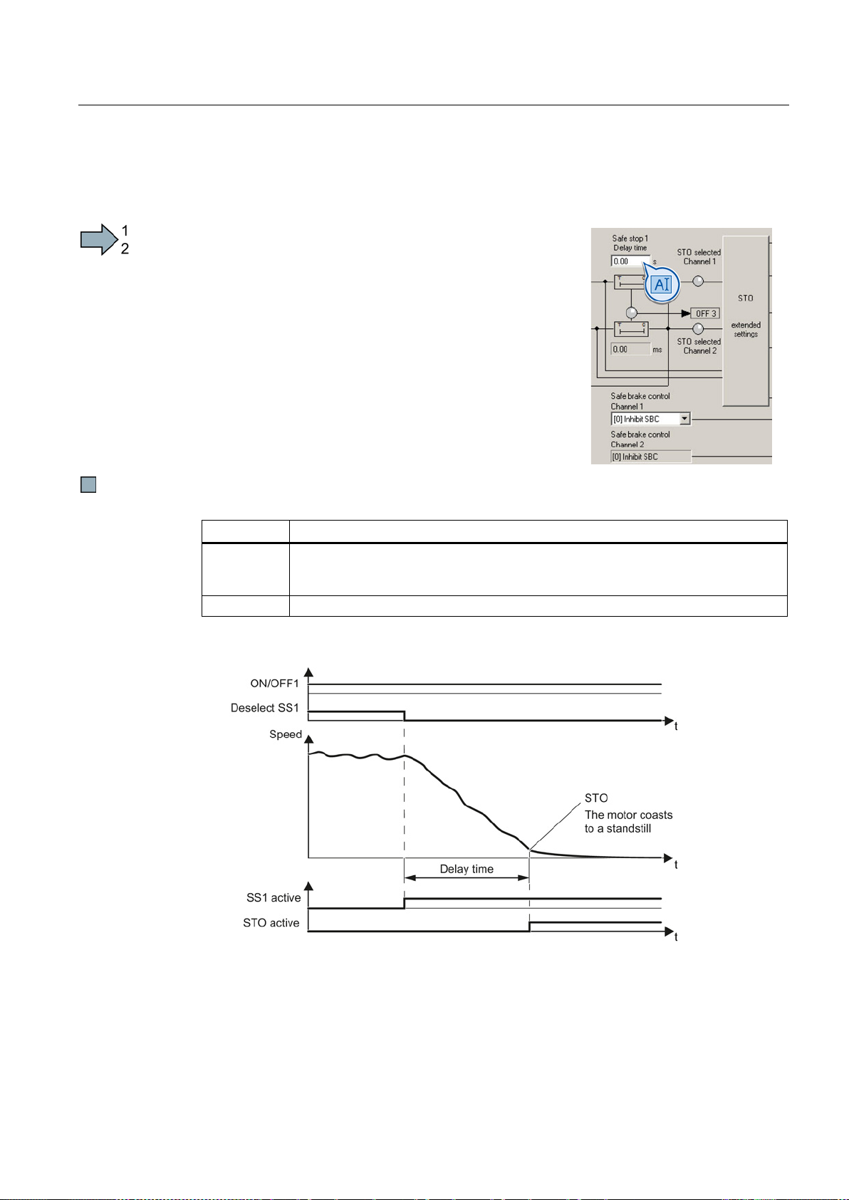
Commissioning
5.6.5
Setting the delay time for SS1
Procedure
Set the delay time for SS1. The delay time
than the OFF3 ramp
Parameter
Description
Safe Stop 1 delay time
brake with the OFF3 ramp-down time.
p1135
OFF3 ramp-down time
Description: the SS1 function without monitoring the speed
5.6 Setting basic functions
must be longer
-down time.
You have set the SS1 function.
p9652
Sets the delay time of the pulse suppression for the "Safe Stop 1" (SS1) function to
Figure 5-5 SS1 without monitoring the speed
When SS1 is selected, the inverter brakes the motor with the OFF3 ramp-down time.
After the delay time, independent of the actual speed, the inverter switches off the motor
torque using the STO function.
Safety Integrated - SINAMICS G110M, G120, G120C, G120D and SIMATIC ET 200pro FC-2
Function Manual, 04/2014, FW V4.7, A5E34261271B AA
99
Page 100
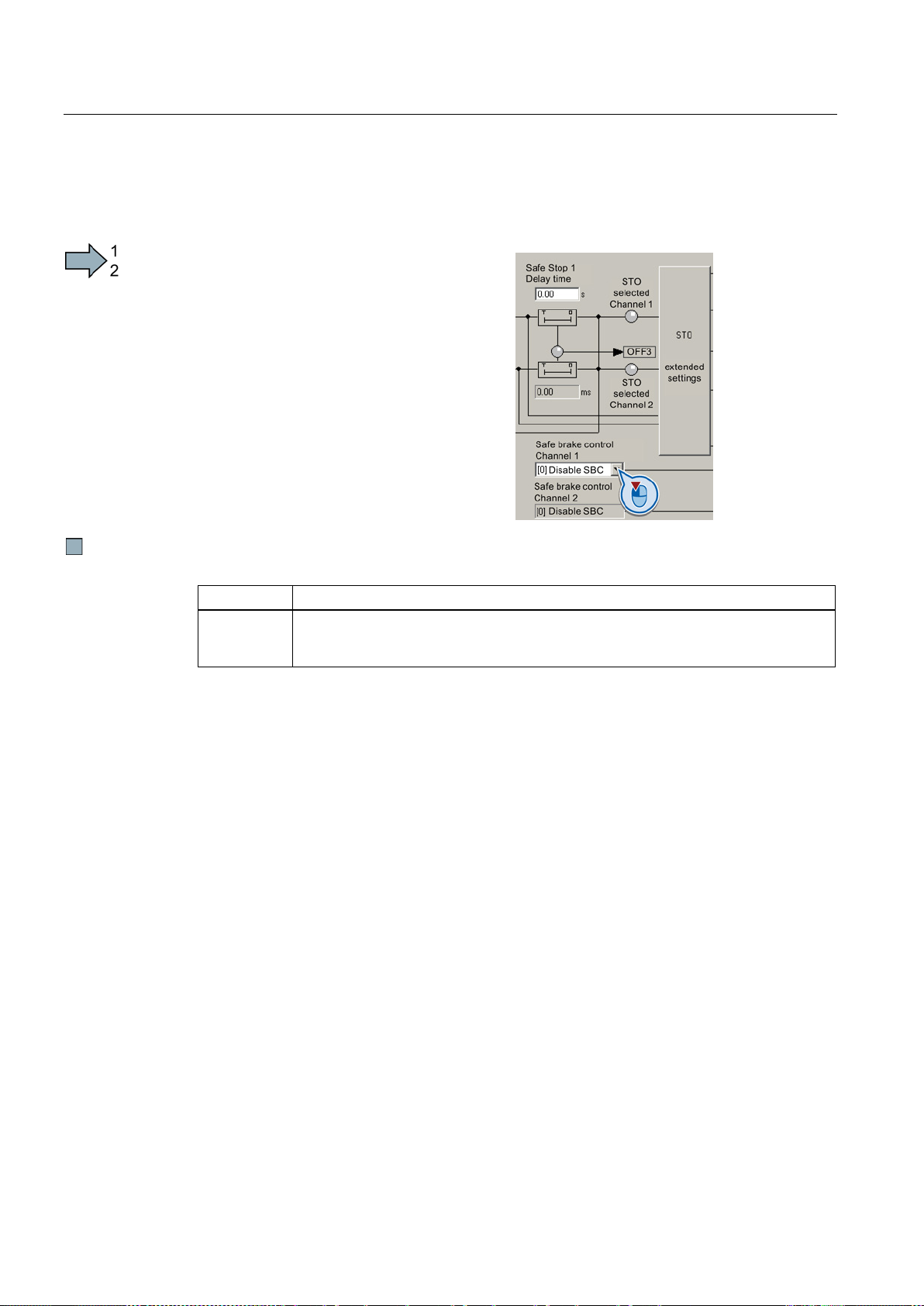
Commissioning
5.6.6
Enabling SBC
Procedure
Enable the SBC function.
Parameter
Description
Enable safe brake control
1: SBC is enabled
5.6 Setting basic functions
You have enabled the SBC function.
p9602
0: SBC is locked
Safety Integrated - SINAMICS G110M, G120, G120C, G120D and SIMATIC ET 200pro FC-2
100 Function Manual, 04/2014, FW V4.7, A5E34261271B AA
 Loading...