

Siemens SIMATIC ET 200eco User Manual

SIMATIC
Preface, Contents
1
Product Overview
2
Installation
ET 200eco
Distributed I/O Station
Manual
Wiring
Commissioning and diagnostics
General Technical Data
Technical Data
Appendices
Order Numbers
Dimensional Drawings
I/O Address Area
3
4
5
6
A
B
C
This manual has the order number
6ES7198-8GA00-8BA0
Edition 02/2003
A5E00158716-02
Glossary, Index
Safety Guidelines
This manual contains notices intended to ensure personal safety, as well as to protect the products and
connected equipment against damage. These notices are highlighted by the symbols shown below and
graded according to severity by the following texts:
Danger
!
indicates that death, severe personal injury or substantial property damage will result if proper precautions
are not taken.
Warning
!
indicates that death, severe personal injury or substantial property damage can result if proper
precautions are not taken.
Caution
!
indicates that minor personal injury can result if proper precautions are not taken.
Caution
indicates that property damage can result if proper precautions are not taken.
Notice
draws your attention to particularly important information on the product, handling the product, or to a
particular part of the documentation.
Qualified Personnel
Only qualified personnel should be allowed to install and work on this equipment. Qualified persons are
defined as persons who are authorized to commission, to ground and to tag circuits, equipment, and
systems in accordance with established safety practices and standards.
Correct Usage
Note the following:
Warning
!
Trademarks
The reproduction, transmission or use of this document or its
contents is not permitted without express written authority.
Offenders will be liable for damages. All rights, including rights
created by patent grant or registration of a utility model or
design, are reserved.
Siemens AG
Bereich Automation and Drives
Geschaeftsgebiet Industrial Automation Systems
Postfach 4848, D- 90327 Nuernberg
Siemens Aktiengesellschaft A5E00158716-02
This device and its components may only be used for the applications described in the catalog or the
technical description, and only in connection with devices or components from other manufacturers which
have been approved or recommended by Siemens.
This product can only function correctly and safely if it is transported, stored, set up, and installed
correctly, and operated and maintained as recommended.
SIMATIC, SIMATIC HMI and SIMA TIC NET are registered trademarks of SIEMENS AG.
Third parties using for their own purposes any other names in this document which refer to trademarks
might infringe upon the rights of the trademark owners.
Disclaim of LiabilityCopyright W Siemens AG 2002-2003 All rights reserved
We have checked the contents of this manual for agreement
with the hardware and software described. Since deviations
cannot be precluded entirely, we cannot guarantee full
agreement. However, the data in this manual are reviewed
regularly and any necessary corrections included in
subsequent editions. Suggestions for improvement are
welcomed.
Siemens AG 2003
Technical data subject to change.

Preface
Purpose of this manual
The information in this manual helps you to operate the ET 200eco distributed
I/O station as DP slave on PROFIBUS DP.
Basic knowledge required
To understand the manual, you require general experience in the field of
automation engineering.
This manual edition contains a description of the components valid at the time of
its release. We reserve the right to append a Product Information that contains
up–to–date information on new components or components of a new version.
Range of validity of this manual
This manual is valid for the ET 200eco distributed I/O station.
Changes as compared to the previous version
This manual contains the following changes and additions as compared to the
previous manual:
• I/O module 16 DO 0.5 A (6ES7 142-3BH00-0XA0)
• I/O module 8 DI / 8 DO 1.3 A (6ES7 143-3BH00-0XA0)
Note: You tell the previous version of the ET 200eco manual by the number
indicated in the footer: A5E00158716-01.
The number of this manual is: A5E00158716-02.
CE label
The product series SIMATIC S7- ET 200eco distributed I/O station is compliant
with requirements and protective aims of following EU guidelines.
• EU guideline 73/23/EEC “Low–voltage guidelines”
• EU guideline 89/336/EEC “EMC compatibility”
C-Tick-Mark
The product series SIMATIC S7- ET 200eco distributed I/O station is compliant
with the standard AS/NZS 2064 (Australia and New Zealand).
ET 200eco Distributed I/O Station
A5E00158716-02
iii

Preface
Standards
The product series SIMATIC S7 ET 200eco distributed I/O station is compliant with
requirements and criteria of IEC 61131–2.
The ET 200eco distributed I/O station is based on the IEC 61784-1:2002 Ed1
CP 3/1 standard.
Its place in information technology
In addition to this documentation, you require the corresponding manual for your
DP master.
Manual
This manual describes the hardware of your ET 200eco distributed I/O station. It
consists of introductory chapters and reference chapters (technical specifications).
The manual deals with the following topics:
• Installation and wiring of the ET 200eco distributed I/O station
• Commissioning and diagnostics of the ET 200eco distributed I/O station
• Components of the ET 200eco distributed I/O station
• Order Numbers
• The glossary contains explanations of important terms.
• The index helps you to quickly find textual information on important keywords.
Recycling and disposal
ET 200eco equipment can be recycled due to the low content of harmful
substances in its components.
Please contact a company certified for disposal of electronic waste material for
environment friendly recycling and disposal of your old equipment.
iv
ET 200eco Distributed I/O Station
A5E00158716-02

Further support
Please contact your local SIEMENS partner if you have any further queries on the
products described in this manual.
http://www.ad.siemens.de/partner
Training Centers
We offer a range of courses to help you get started with the ET 200eco distributed
I/O station and the SIMATIC S7 PLCs. Please contact your local training center or
the central training center in
D 90327 Nuremberg.
Phone: +49 (911) 895-3200.
Internet: http://www.sitrain.com
Preface
ET 200eco Distributed I/O Station
A5E00158716-02
v

Preface
A&D Technical Support
Open round the clock, worldwide:
Johnson City
Nuremberg
Beijing
T echnical Support
Worldwide (Nuremberg)
T echnical Support
Local time:0:00 to 24:00 / 365 days
Phone: +49 (0) 180 5050-222
Phone: +49 (0) 180 5050-223
E-Mail: adsupport@
GMT: +1:00
Europe/Africa (Nuremberg)
Authorization
siemens.com
United States (Johnson City)
Technical Support and
Authorization
Local time: 8:00 to 17:00
Phone: +49 (0) 180 5050-222
Phone: +49 (0) 180 5050-223
E-Mail: adsupport@
siemens.com
GMT: +1:00
German and English spoken at the Technical Support and Authorization hotlines.
Local time: 8:00 to 17:00
Phone: +1 (0) 423 262 2522
Fax: +1 (0) 423 262 2289
E-Mail: simatic.hotline@
sea.siemens.com
GMT: –5:00
Asia/Australia (Beijing)
Technical Support and
Authorization
Local time: 8:00 to 17:00
Phone: +86 10 64 75 75 75
Fax: +86 10 64 74 74 74
E-mail: adsupport.asia@
siemens.com
GMT: +8:00
vi
ET 200eco Distributed I/O Station
A5E00158716-02

Service & Support on the Internet
In addition to our documentation services, we also offer you our knowledge base
on the Internet.
http://www.ad.siemens.de/support
Here, you will find:
• our Newsletter, a source that offers updated information on your products
• your appropriate documentation via our Service & Support search engine
• a forum for the exchange of information between users and specialists
worldwide
• your local Automation & Drives partner via our partner database.
• information on repairs, replacement parts and on–site service. Please refer to
our ”Service” pages for further topics.
Preface
ET 200eco Distributed I/O Station
A5E00158716-02
vii

Preface
viii
ET 200eco Distributed I/O Station
A5E00158716-02

Contents
1 Product overview 1-1. . . . . . . . . . . . . . . . . . . . . . . . . . . . . . . . . . . . . . . . . . . . . . . . . . . . . . .
1.1 What are distributed I/O stations? 1-2. . . . . . . . . . . . . . . . . . . . . . . . . . . . . . . . .
1.2 What is the ET 200eco distributed I/O station? 1-4. . . . . . . . . . . . . . . . . . . . . .
2 Installation 2-1. . . . . . . . . . . . . . . . . . . . . . . . . . . . . . . . . . . . . . . . . . . . . . . . . . . . . . . . . . . . .
2.1 Mounting position/dimensions 2-1. . . . . . . . . . . . . . . . . . . . . . . . . . . . . . . . . . . . .
2.2 I/O module installation 2-2. . . . . . . . . . . . . . . . . . . . . . . . . . . . . . . . . . . . . . . . . . .
2.3 Installation of the terminal block 2-3. . . . . . . . . . . . . . . . . . . . . . . . . . . . . . . . . . .
2.4 Label replacement 2-4. . . . . . . . . . . . . . . . . . . . . . . . . . . . . . . . . . . . . . . . . . . . . . .
2.5 Removing ET 200eco 2-5. . . . . . . . . . . . . . . . . . . . . . . . . . . . . . . . . . . . . . . . . . . .
2.6 PROFIBUS address assignment 2-6. . . . . . . . . . . . . . . . . . . . . . . . . . . . . . . . . .
3 Wiring 3-1. . . . . . . . . . . . . . . . . . . . . . . . . . . . . . . . . . . . . . . . . . . . . . . . . . . . . . . . . . . . . . . . .
3.1 General rules and regulations for the operation of ET 200eco 3-1. . . . . . . . .
3.2 ET 200eco operation on a grounded power supply 3-2. . . . . . . . . . . . . . . . . . .
3.3 Electrical structure of the ET 200eco system 3-4. . . . . . . . . . . . . . . . . . . . . . . .
3.4 Wiring ET 200eco 3-7. . . . . . . . . . . . . . . . . . . . . . . . . . . . . . . . . . . . . . . . . . . . . . .
3.4.1 How to connect ET 200eco to protective earth (PE) 3-8. . . . . . . . . . . . . . . . . .
3.4.2 How to wire I/O modules 3-9. . . . . . . . . . . . . . . . . . . . . . . . . . . . . . . . . . . . . . . . .
3.4.3 How to wire the ECOFAST terminal block 3-19. . . . . . . . . . . . . . . . . . . . . . . . . .
3.4.4 Wiring the M12, 7/8” terminal block 3-23. . . . . . . . . . . . . . . . . . . . . . . . . . . . . . . .
3.4.5 How to loop the PROFIBUS DP and the supply voltage 3-27. . . . . . . . . . . . . . .
4 Commissioning and diagnostics 4-1. . . . . . . . . . . . . . . . . . . . . . . . . . . . . . . . . . . . . . . .
4.1 ET 200eco configuration 4-2. . . . . . . . . . . . . . . . . . . . . . . . . . . . . . . . . . . . . . . . .
4.2 ET 200eco commissioning and startup 4-3. . . . . . . . . . . . . . . . . . . . . . . . . . . . .
4.3 Diagnostics with LED display 4-5. . . . . . . . . . . . . . . . . . . . . . . . . . . . . . . . . . . . .
4.4 ET 200eco diagnostics 4-8. . . . . . . . . . . . . . . . . . . . . . . . . . . . . . . . . . . . . . . . . . .
4.4.1 Reading diagnostic data 4-8. . . . . . . . . . . . . . . . . . . . . . . . . . . . . . . . . . . . . . . . . .
4.4.2 Structure of ET 200eco slave diagnostics 4-11. . . . . . . . . . . . . . . . . . . . . . . . . . .
4.4.3 Station status 1 to 3 4-12. . . . . . . . . . . . . . . . . . . . . . . . . . . . . . . . . . . . . . . . . . . . .
4.4.4 Master PROFIBUS address 4-14. . . . . . . . . . . . . . . . . . . . . . . . . . . . . . . . . . . . . .
4.4.5 Manufacturer ID 4-14. . . . . . . . . . . . . . . . . . . . . . . . . . . . . . . . . . . . . . . . . . . . . . . . .
4.4.6 Device–specific diagnostic data 4-15. . . . . . . . . . . . . . . . . . . . . . . . . . . . . . . . . . .
ET 200eco Distributed I/O Station
A5E00158716-02
ix

Contents
5 General technical data 5-1. . . . . . . . . . . . . . . . . . . . . . . . . . . . . . . . . . . . . . . . . . . . . . . . . .
5.1 Standards and approvals 5-2. . . . . . . . . . . . . . . . . . . . . . . . . . . . . . . . . . . . . . . . .
5.2 EMC compatibility, shipping and storage conditions 5-3. . . . . . . . . . . . . . . . . .
5.3 Mechanical and climatic ambient conditions 5-5. . . . . . . . . . . . . . . . . . . . . . . . .
5.4 Specification of isolation tests, protection class,
type of protection and rated voltage for ET 200eco 5-7. . . . . . . . . . . . . . . . . . .
6 Technical data 6-1. . . . . . . . . . . . . . . . . . . . . . . . . . . . . . . . . . . . . . . . . . . . . . . . . . . . . . . . . .
6.1 ECOFAST terminal block (6ES7 194-3AA00-0AA0) 6-2. . . . . . . . . . . . . . . . . .
6.2 Terminal block M12, 7/8” (6ES7 194-3AA00-0BA0) 6-4. . . . . . . . . . . . . . . . . . .
6.3 I/O module 8 DI (6ES7 141-3BF00-0XA0) 6-7. . . . . . . . . . . . . . . . . . . . . . . . . .
6.4 I/O module 16 DI (6ES7 141-3BH00-0XA0) 6-10. . . . . . . . . . . . . . . . . . . . . . . . .
6.5 I/O module 8 DO 2A (6ES7 142-3BF00-0XA0) 6-13. . . . . . . . . . . . . . . . . . . . . .
6.6 I/O module 16 DO 0.5 A (6ES7 142-3BH00-0XA0) 6-16. . . . . . . . . . . . . . . . . . .
6.7 I/O module 8 DI / 8 DO 2 A (6ES7 143-3BH00-0XA0) 6-19. . . . . . . . . . . . . . . .
6.8 I/O module 8 DI / 8 DO 1.3 A
(6ES7 143-3BH00-0XA0) 6-22. . . . . . . . . . . . . . . . . . . . . . . . . . . . . . . . . . . . . . . . .
A Order numbers A-1. . . . . . . . . . . . . . . . . . . . . . . . . . . . . . . . . . . . . . . . . . . . . . . . . . . . . . . . .
B Dimensional drawings B-1. . . . . . . . . . . . . . . . . . . . . . . . . . . . . . . . . . . . . . . . . . . . . . . . . .
C I/O address area C-1. . . . . . . . . . . . . . . . . . . . . . . . . . . . . . . . . . . . . . . . . . . . . . . . . . . . . . . .
Glossary Glossary-1. . . . . . . . . . . . . . . . . . . . . . . . . . . . . . . . . . . . . . . . . . . . . . . . . . . . . . . . . .
Index Index-1. . . . . . . . . . . . . . . . . . . . . . . . . . . . . . . . . . . . . . . . . . . . . . . . . . . . . . . . . . . . . . . .
x
ET 200eco Distributed I/O Station
A5E00158716-02

Figures
1-1 Typical structure of a PROFIBUS-DP network 1-3. . . . . . . . . . . . . . . . . . . . . . .
1-2 View of the ET 200eco distributed I/O station 1-4. . . . . . . . . . . . . . . . . . . . . . . .
2-1 Mounting the I/O module onto the base 2-3. . . . . . . . . . . . . . . . . . . . . . . . . . . . .
2-2 Inserting and screw–tightening the terminal block at the I/O module 2-4. . . .
2-3 Removing labels 2-5. . . . . . . . . . . . . . . . . . . . . . . . . . . . . . . . . . . . . . . . . . . . . . . .
2-4 How to set the PROFIBUS-DP address at terminal block M12, 7/8” 2-7. . . .
2-5 How to unscrew the configuration module 2-8. . . . . . . . . . . . . . . . . . . . . . . . . . .
2-6 How to set the PROFIBUS address at the configuration module 2-8. . . . . . .
3-1 ET 200eco operation with reference potential bonded to
equipotential earth 3-4. . . . . . . . . . . . . . . . . . . . . . . . . . . . . . . . . . . . . . . . . . . . . . .
3-2 Potentials in an ET 200eco installation with M12, 7/8” terminal block 3-5. . .
3-3 Potentials in an ET 200eco installation with ECOFAST terminal block 3-6. .
3-4 Connecting the I/O module to protective earth 3-9. . . . . . . . . . . . . . . . . . . . . . .
3-5 How to connect the M12 plug 3-14. . . . . . . . . . . . . . . . . . . . . . . . . . . . . . . . . . . . .
3-6 Y connector 3-15. . . . . . . . . . . . . . . . . . . . . . . . . . . . . . . . . . . . . . . . . . . . . . . . . . . .
3-7 Connecting the ECOFAST connector 3-21. . . . . . . . . . . . . . . . . . . . . . . . . . . . . .
3-8 Connecting the ECOFAST connector 3-22. . . . . . . . . . . . . . . . . . . . . . . . . . . . . .
3-9 How to wire the M12, 7/8” plug 3-25. . . . . . . . . . . . . . . . . . . . . . . . . . . . . . . . . . . .
3-10 How to connect the M12 terminating resistor 3-26. . . . . . . . . . . . . . . . . . . . . . . .
3-11 Loop–through of the PROFIBUS DP and power bus 3-27. . . . . . . . . . . . . . . . .
4-1 ET 200eco startup 4-4. . . . . . . . . . . . . . . . . . . . . . . . . . . . . . . . . . . . . . . . . . . . . . .
4-2 LED display on the ET 200eco 4-5. . . . . . . . . . . . . . . . . . . . . . . . . . . . . . . . . . . .
4-3 Structure of ET 200eco slave diagnostics data 4-11. . . . . . . . . . . . . . . . . . . . . .
4-4 Structure of ET 200eco device–specific diagnostics data 4-15. . . . . . . . . . . . . .
6-1 Block diagram of the ECOFAST terminal block 6-3. . . . . . . . . . . . . . . . . . . . . .
6-2 Block diagram of the M12, 7/8” terminal module 6-6. . . . . . . . . . . . . . . . . . . . .
6-3 Block diagram of I/O module 8 DI 6-8. . . . . . . . . . . . . . . . . . . . . . . . . . . . . . . . . .
6-4 Block diagram of I/O module 16 DI 6-11. . . . . . . . . . . . . . . . . . . . . . . . . . . . . . . .
6-5 Block diagram of I/O module 8 DO 2A 6-14. . . . . . . . . . . . . . . . . . . . . . . . . . . . . .
6-6 Block diagram of I/O module 16 DO 0.5 A 6-17. . . . . . . . . . . . . . . . . . . . . . . . . .
6-7 Block diagram of I/O module 8 DI / 8 DO 2A 6-20. . . . . . . . . . . . . . . . . . . . . . . .
6-8 Block diagram of I/O module 8 DI / 8 DO 1.3 A 6-24. . . . . . . . . . . . . . . . . . . . . .
B-1 Dimensional drawing of an I/O module with installed M12, 7/8”
terminal block B-1. . . . . . . . . . . . . . . . . . . . . . . . . . . . . . . . . . . . . . . . . . . . . . . . . . .
B-2 Dimensional drawing of an I/O module with installed ECOFAST
terminal block B-2. . . . . . . . . . . . . . . . . . . . . . . . . . . . . . . . . . . . . . . . . . . . . . . . . . .
C-1 Address area of I/O module 8 DI C-1. . . . . . . . . . . . . . . . . . . . . . . . . . . . . . . . . .
C-2 Address space of I/O module 16 DI C-2. . . . . . . . . . . . . . . . . . . . . . . . . . . . . . . .
C-3 Address area of I/O module 8 DO 2 A C-2. . . . . . . . . . . . . . . . . . . . . . . . . . . . . .
C-4 Address area of I/O module 16 DO 0.5 A C-3. . . . . . . . . . . . . . . . . . . . . . . . . . .
C-5 Address area of I/O module 8 DI / 8 DO 2 A C-4. . . . . . . . . . . . . . . . . . . . . . . .
C-6 Address area of I/O module 8 DI / 8 DO 1.3 A C-5. . . . . . . . . . . . . . . . . . . . . . .
Contents
ET 200eco Distributed I/O Station
A5E00158716-02
xi

Contents
Tables
1-1 ET 200eco components 1-5. . . . . . . . . . . . . . . . . . . . . . . . . . . . . . . . . . . . . . . . . .
2-1 Mounting dimensions 2-1. . . . . . . . . . . . . . . . . . . . . . . . . . . . . . . . . . . . . . . . . . . .
3-1 Pin assignment of the M12 coupler plug for the I/O module 8 DI 3-10. . . . . . .
3-2 Pin assignment of the M12 coupler plug for the I/O module 16 DI 3-10. . . . . .
3-3 Pin Assignment for M12 Coupler Plug for I/O Module 8 DO 2 A 3-11. . . . . . . .
3-4 Pin assignment of M12 coupler plug for I/O module 16 DO 0.5 A 3-11. . . . . .
3-5 Pin assignment of M12 coupler plug for I/O module
8 DI / 8 DO 2 A 3-12. . . . . . . . . . . . . . . . . . . . . . . . . . . . . . . . . . . . . . . . . . . . . . . . .
3-6 Pin assignment of M12 coupler plug for I/O module
8 DI / 8 DO 1.3 A 3-13. . . . . . . . . . . . . . . . . . . . . . . . . . . . . . . . . . . . . . . . . . . . . . . .
3-7 The Y connector and I/O module 16 DI 3-16. . . . . . . . . . . . . . . . . . . . . . . . . . . . .
3-8 Y connector for I/O module 16 DO 0.5 A 3-16. . . . . . . . . . . . . . . . . . . . . . . . . . . .
3-9 Y connector plug for I/O module 8 DI / 8 DO 2 A 3-17. . . . . . . . . . . . . . . . . . . . .
3-10 Y connector plug for I/O module 8 DI / 8 DO 1.3 A 3-18. . . . . . . . . . . . . . . . . . .
3-11 Pin assignment of the ECOFAST connector 3-20. . . . . . . . . . . . . . . . . . . . . . . . .
3-12 Pin assignment of the M12 plug (PROFIBUS DP) 3-24. . . . . . . . . . . . . . . . . . . .
3-13 Pin assignment of the 7/8” plug (Power bus) 3-24. . . . . . . . . . . . . . . . . . . . . . . .
4-1 GSD file Implementation in the configuration software 4-2. . . . . . . . . . . . . . .
4-2 Software required for commissioning 4-3. . . . . . . . . . . . . . . . . . . . . . . . . . . . . . .
4-3 Prerequisite for commissioning the ET 200eco 4-3. . . . . . . . . . . . . . . . . . . . . .
4-4 Steps for commissioning the DP slave 4-3. . . . . . . . . . . . . . . . . . . . . . . . . . . . .
4-5 Status and error display with LEDs 4-5. . . . . . . . . . . . . . . . . . . . . . . . . . . . . . . .
4-6 Reading diagnostics data of ET 200eco under STEP 7 and STEP 5 4-8. . .
4-7 Structure of the station status 1(byte 0) ET 200eco 4-12. . . . . . . . . . . . . . . . . .
4-8 Structure of station status 2 (byte 1) ET 200eco 4-13. . . . . . . . . . . . . . . . . . . . .
4-9 Structure of station status 3 (byte 2) ET 200eco 4-13. . . . . . . . . . . . . . . . . . . . .
4-10 Structure of the ET 200eco manufacturer ID (bytes 4 and 5) 4-14. . . . . . . . . .
6-1 Pin-out of the sockets X01 and X02 6-2. . . . . . . . . . . . . . . . . . . . . . . . . . . . . . . .
6-2 Pin-out of the plugs DP1 and DP2 (M12) 6-5. . . . . . . . . . . . . . . . . . . . . . . . . . .
6-3 Pin-out of the connectors X01 and X02 (7/8”) 6-5. . . . . . . . . . . . . . . . . . . . . . .
6-4 Pin-out of the digital input sockets X1 to X8 6-7. . . . . . . . . . . . . . . . . . . . . . . . .
6-5 Pin-out of the digital input sockets X1 to X8 6-10. . . . . . . . . . . . . . . . . . . . . . . . .
6-6 Pin-out of the digital output sockets X1 to X8 6-13. . . . . . . . . . . . . . . . . . . . . . . .
6-7 Pin-out of the digital output sockets X1 to X8 6-16. . . . . . . . . . . . . . . . . . . . . . . .
6-8 Pin-out of the digital input and output sockets X1 to X8 6-19. . . . . . . . . . . . . . .
6-9 Pin-out of the digital input and output sockets X1 to X8 6-23. . . . . . . . . . . . . . .
A-1 ET 200eco components – Order numbers A-1. . . . . . . . . . . . . . . . . . . . . . . . . .
A-2 ET 200eco accessories – Order numbers A-1. . . . . . . . . . . . . . . . . . . . . . . . . .
A-3 I/O module accessories – Order numbers A-2. . . . . . . . . . . . . . . . . . . . . . . . . .
A-4 Accessories for the ECOFAST terminal block – Order numbers A-2. . . . . . .
A-5 M12, 7/8” terminal block accessories – Order numbers A-3. . . . . . . . . . . . . .
A-6 STEP 7 and SIMATIC S7 Manual A-4. . . . . . . . . . . . . . . . . . . . . . . . . . . . . . . . . .
A-7 PROFIBUS DP and SIMATIC S7 Manual A-4. . . . . . . . . . . . . . . . . . . . . . . . . . .
xii
ET 200eco Distributed I/O Station
A5E00158716-02

Product overview
In this chapter
This product information shows you
• the place of the ET 200eco distributed I/O station in the ET 200 distributed I/O
station and
• the components comprising the ET 200eco distributed I/O station.
Chapter overview
Chapter Topic Page
1.1 What are distributed I/O stations? 1-2
1.2 What is the ET 200eco distributed I/O system? 1-4
1
ET 200eco Distributed I/O Station
A5E00158716-02
1-1

Product overview
1.1 What are distributed I/O stations?
Distributed I/O systems – Field of application
Many systems are configured with a centralized process I/O system in the local
PLC.
Greater distances between remote I/O and the PLC can result in badly arranged
and extensive wiring. Also, electromagnetic interference may reduce reliabilty.
Plants of this type are suitable for operation with distributed I/O systems:
• local controlling CPU
• distributed I/O systems (inputs and outputs) operate at remote locations
• the high–performance PROFIBUS-DP provides high data transmission rates for
trouble–free communication between the controlling CPU and the I/O systems.
What is PROFIBUS–DP?
PROFIBUS-DP is an open bus system according to the IEC 61784-1:2002 Ed1CP
3/1 standard with a “DP” transfer protocol (DP stands for distributed periphery, or
distributed I/O).
PROFIBUS-DP is physically an electrical network that is based on shielded twisted
pair cables or optical waveguide networking.
The ”DP” protocol allows fast, cyclic data exchange between the controlling CPU
and distributed I/O systems.
What are DP masters and DP slaves?
The DP master forms the interface between the controlling CPU and the
distributed I/O system. The DP master exchanges data with distributed I/O
systems via PROFIBUS-DP and monitors the PROFIBUS DP.
Distributed I/O systems (= DP slaves) prepare sensors and actuator data locally
for their transfer to the PLC via PROFIBUS DP.
Which devices can I connect to PROFIBUS-DP?
A wide range of devices can be connected on the PROFIBUS-DP as DP masters
or DP slaves, provided that they operate in accordance with IEC 61784-1:2002
Ed1 CP 3/1. Among others, devices from the following product families can be
used:
1-2
• SIMATIC S5
• SIMATIC S7/M7/C7
• SIMATIC programming devices/PCs
• SIMATIC HMI (operator control and monitoring stations OP, OS, TD)
• Devices from other vendors
ET 200eco Distributed I/O Station
A5E00158716-02
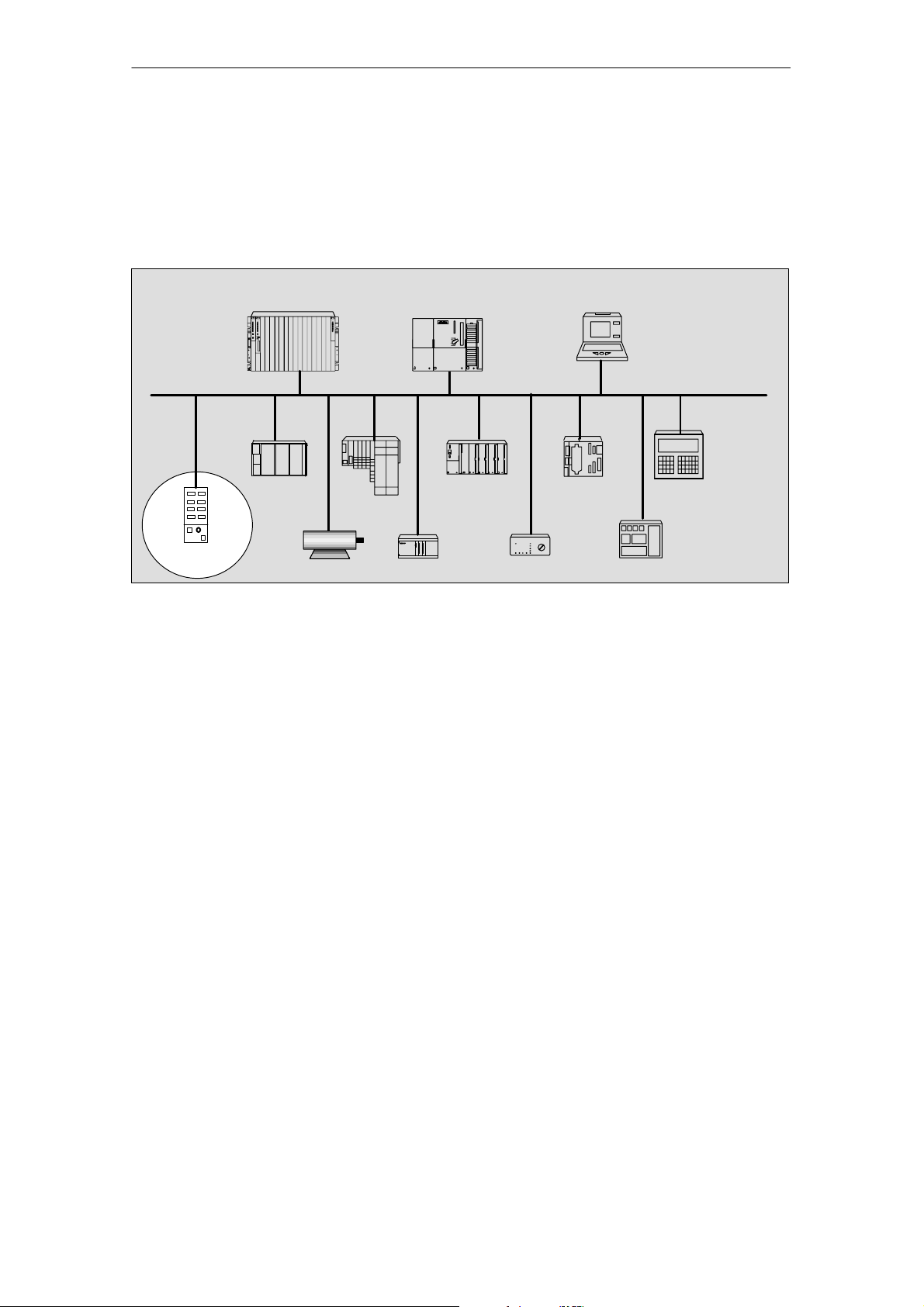
Structure of a PROFIBUS-DP network
The figure below shows you a typical PROFIBUS DP network structure. The DP
masters are integrated in the corresponding unit, e.g. the S7-400 or S7-300 is
equipped with a PROFIBUS-DP interface. The DP slaves, namely the distributed
I/O, are interconnected to the DP masters via PROFIBUS DP.
Product overview
S7-400
ET 200X
ET 200S
ET200eco
drive
Figure 1-1 Typical structure of a PROFIBUS-DP network
S7-300
ET 200M S5-95U-DP
S7-200
DP/AS–I Link
PG/PC
DP master
PROFIBUS-DP
DP slaves
OP/OS
further field devices
ET 200eco Distributed I/O Station
A5E00158716-02
1-3
Product overview
1.2 What is the ET 200eco distributed I/O station?
Definition
The ET 200eco distributed I/O station is a compact DP slave (degree of protection
IP 65, IP 66 or IP 67).
Field of application
• Due to its rugged design and degree of protection IP 65, IP 66 or IP 67, the
ET 200eco distributed I/O station is primarily suitable for operation under harsh
industrial conditions.
• The compact design of ET 200eco allows its use in confined areas and
• its easy handling features ensure efficient commissioning and maintenance.
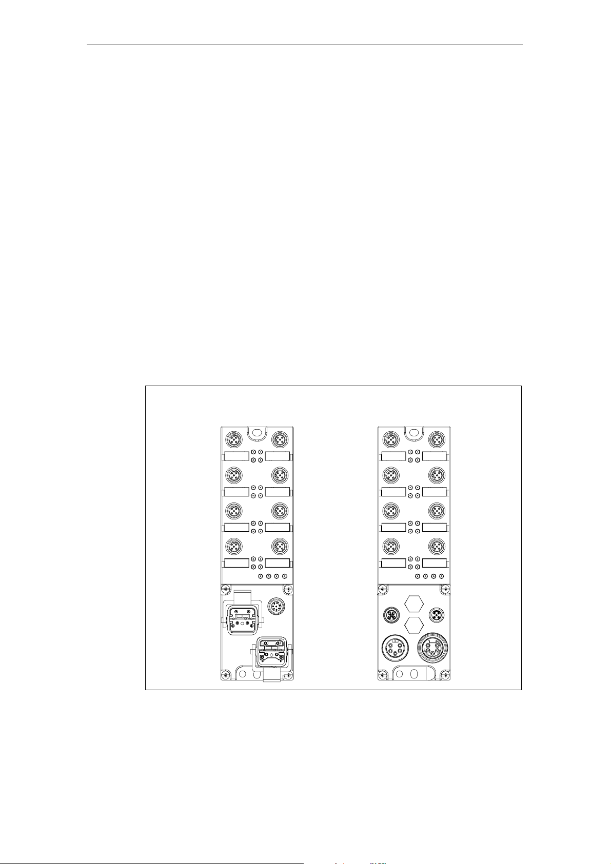
View
The ET 200eco consists of an I/O module and a terminal block. These components
are available in different versions.
ET 200eco with ECO-
FAST terminal block
ET 200eco with M12,
7/8”terminal block
1-4
Figure 1-2 View of the ET 200eco distributed I/O station
ET 200eco Distributed I/O Station
A5E00158716-02
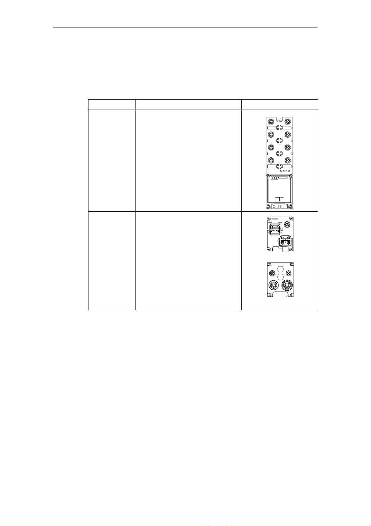
ET200eco components
The table provides an overview of the major components of ET 200eco:
Table 1-1 ET 200eco components
Product overview
Component
I/O module You connect sensors and actuators to
the I/O module. The I/O module is
available in the following versions:
Function Figure
• 8 DI
• 16 DI
• 8 DO 2A
• 16 DO 0.5 A
• 8 DI / 8 DO 2A
• 8 DI / 8 DO 1.3 A
Terminal block You connect the ET 200eco power
supply and the PROFIBUS-DP cable to
the terminal block. The terminal block is
available in the following versions:
• ECOFAST
• M12, 7/8”
DP master
The ET 200eco station can communicate with all DP masters that operate
according to IEC 61784-1:2002 Ed1 CP 3/1.
ET 200eco Distributed I/O Station
A5E00158716-02
1-5

Product overview
1-6
ET 200eco Distributed I/O Station
A5E00158716-02

Installation
Easy installation
The design of the ET 200eco distributed I/O station allows easy installation.
Chapter overview
Chapter Topic Page
2.1 Mounting position/dimensions 2-1
2.2 I/O module installation 2-2
2.3 Installation of the terminal block 2-3
2.4 Label replacement 2-4
2.5 Removing ET 200eco 2-5
2.6 Setting the PROFIBUS address 2-6
2
2.1 Mounting position/dimensions
Mounting position
The ET 200eco can be mounted in any position
Mounting and spacing dimensions
Table 2-1 Mounting dimensions
Dimensions
Mounting width 60 mm
Mounting height 210 mm
Mounting depth • with terminal block ECOFAST: 60 mm (without plug)
• with terminal block M12, 7/8”: 54 mm (without plug)
ET 200eco Distributed I/O Station
A5E00158716-02
2-1

Installation
2.2 I/O module installation
Properties
• The I/O module must be mounted onto a solid base.
• The I/O module (without terminal block) can be prewired.
Requirements
Screws:
Screw type Explanation
M5 cylindrical head screw to ISO
1207/ISO 1580 (DIN 84/DIN 85)
Cylindrical head screw with M5
hexagonal socket to DIN 912
Tools required
Medium size Pillipps screwdriver or 8 mm socket wrench
Minimum screw length: 20 mm.
Additionally required: DIN 125 washers.
Additionally required: DIN 125 washers.
2-2
ET 200eco Distributed I/O Station
A5E00158716-02
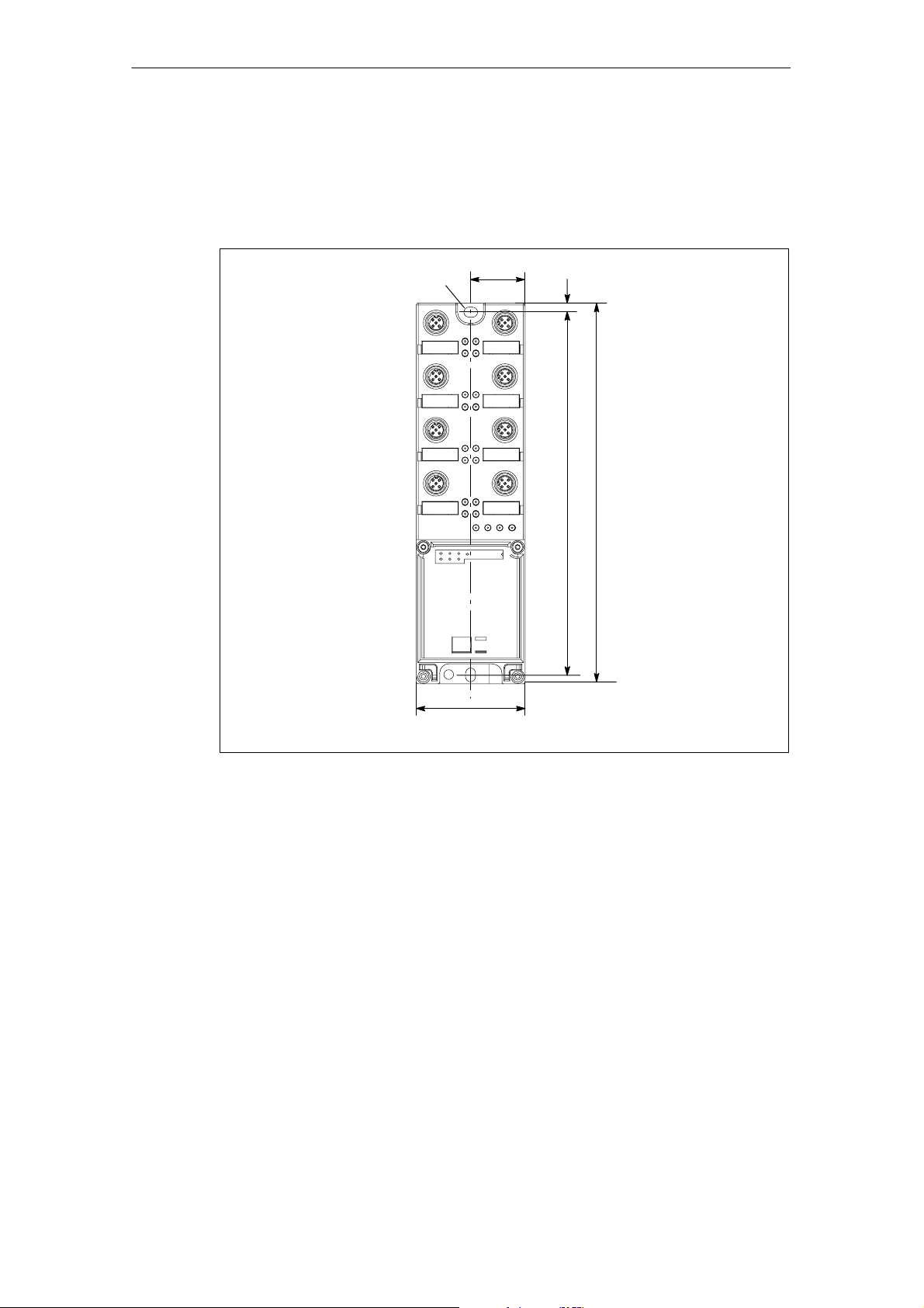
Procedure
Installation
Using the screws, tighten the I/O module onto a level base. The I/O module must
be screwed onto the base at both fastening points (at the front panel top and
bottom). Tightening torque: 3 N/m.
5.5 x 7
30
5
210
200
60
Figure 2-1 Mounting the I/O module onto the base
2.3 Installation of the terminal block
Properties
The terminal block connects the ET 200eco to the power supply and to the
PROFIBUS DP network.
Requirements
The I/O module is installed.
Tools required
Medium size Phillips screwdriver
ET 200eco Distributed I/O Station
A5E00158716-02
2-3
Installation
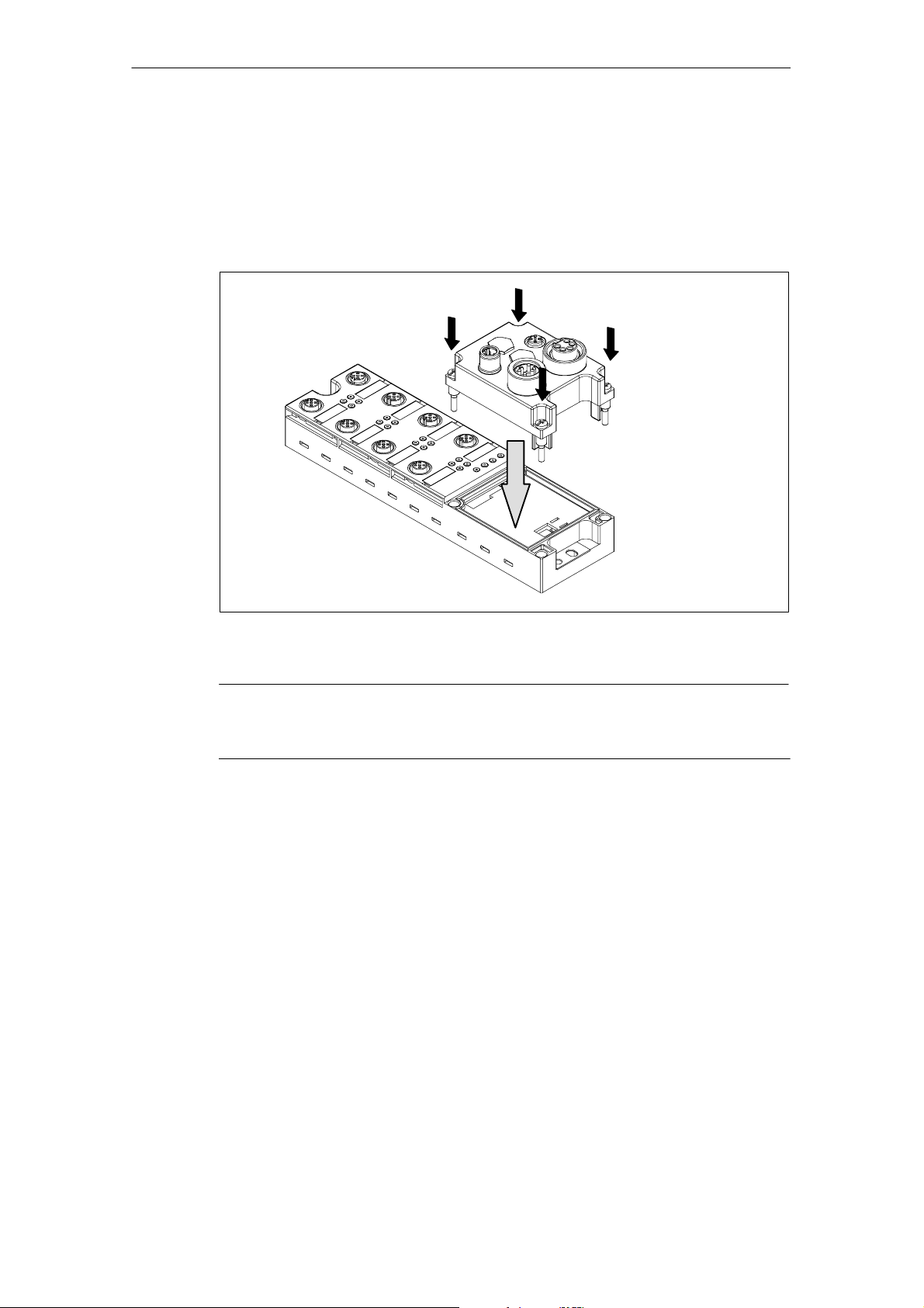
Installation of the terminal block
1. Insert the terminal block into the I/O module.
2. Bolt the terminal block to the I/O module (with a torque of 1 to 1.3 nm). Tighten
the screws evenly in diagonally opposite sequence.
The terminal block is equipped with four captive screws (see Figure 2-2).
2
2
2
1
Figure 2-2 Inserting and screw–tightening the terminal block at the I/O module
Note
The protection type IP 65, IP 66 or IP 67 is only ensured after the terminal block is
screwed tight onto the I/O module!
2
2.4 Label replacement
Properties
You can use these labels to identify each of the I/O module’s channels and the
terminal block. The system is supplied with snap–on labels:
• 8 labels on the I/O module
• 1 label on the terminal block
Requirements
Replacement labels are available on order. For order numbers please refer to
Appendix A.
2-4
ET 200eco Distributed I/O Station
A5E00158716-02
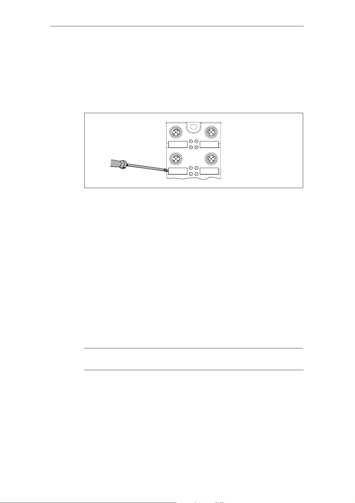
Tools required
Screwdriver, 2.5 mm to 4 mm blade
Label replacement
1. Insert the screwdriver into the small opening on the label and lever it out.
Installation
1
Figure 2-3 Removing labels
2. Snap the new label tag into the holder on the module.
2.5 Removing ET 200eco
Procedure
The ET 200eco is wired and in operation.
1. Switch off the ET 200eco power supply.
2. Disconnect the terminal block wiring.
3. Unscrew the terminal block and remove it from the I/O module.
4. Disconnect the wiring on the I/O module.
5. Unscrew the I/O module.
Note
Please note Chapter 3.4.5 before you replace the I/O module.
ET 200eco Distributed I/O Station
A5E00158716-02
2-5

Installation
2.6 PROFIBUS address assignment
Properties
Specify the PROFIBUS address under which the ET 200eco I/O station is
accessed on PROFIBUS DP.
Requirements
• The PROFIBUS-DP address for ET 200eco is set at the terminal block.
• All PROFIBUS-DP addresses must be unique.
• The set PROFIBUS address must match the PROFIBUS address specified in
your configuration software (for this ET 200eco).
• A change of PROFIBUS–DP address is only valid after the ET 200eco has
been powered up (power ON).
Tools required
• 14 mm socket wrench
• Screwdriver with 2.5 mm blade
2-6
ET 200eco Distributed I/O Station
A5E00158716-02
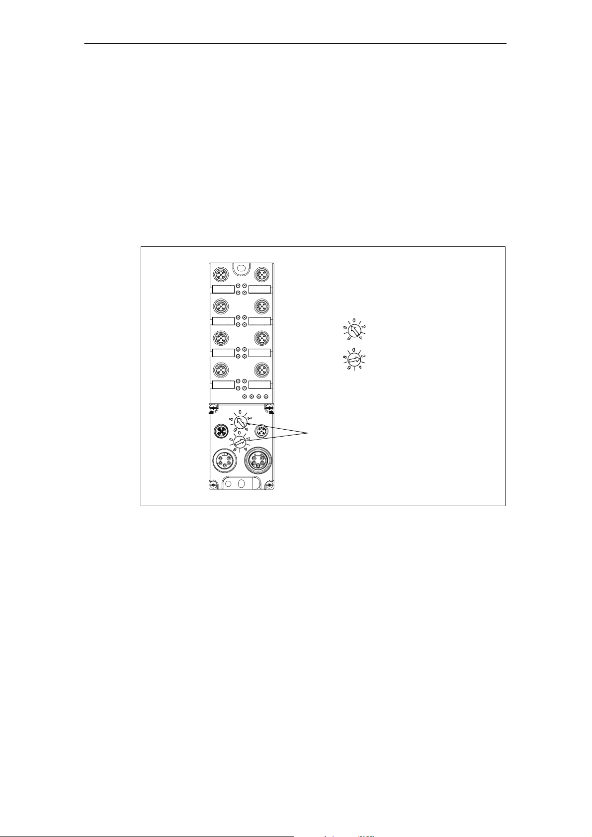
How to set the PROFIBUS-DP address at the terminal block M12, 7/8”
The permitted PROFIBUS-DP address range is 1 to 99.
1. Remove both lock caps on the rotary selector switches (use the 14–mm socket
wrench if need be).
2. Using the screwdriver, set the required PROFIBUS address on the selector
switches.
– Lower selector switch: one’s place
– Upper selector switch: ten’s place
3. Screw the two caps onto the selector switches again (Torque : 0.5 to 0.8 N/m).
Example PROFIBUS address 92:
x10
Position 9
Installation
x1
Position 2
x10
Rotary selector
x1
switch for setting
the PROFIBUS
address
Figure 2-4 How to set the PROFIBUS-DP address at terminal block M12, 7/8”
ET 200eco Distributed I/O Station
A5E00158716-02
2-7
Installation
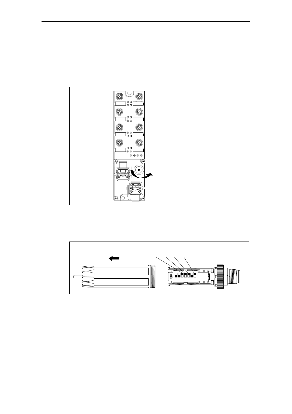
How to set the PROFIBUS-DP address at the ECOFAST terminal block
Valid range of the PROFIBUS DP addresses: 1 to 99. If you select a higher
address, the I/O module will return an error signal via the red bus error LED.
1. Unscrew and remove the configuration module from the ECOFAST terminal
block.
1
Figure 2-5 How to unscrew the configuration module
2. Unscrew and remove the cap of the configuration module.
3. Set the PROFIBUS address on the DIL switches.
Example: PROFIBUS address 92
22 + 23 + 24 + 26 = 4 + 8 + 16 + 64 = 92
2
ON ON
1723456
Figure 2-6 How to set the PROFIBUS address at the configuration module
4. Screw on the cap again. Reinsert the configuration module and fasten it on the
terminal block with the screws.
2-8
ET 200eco Distributed I/O Station
A5E00158716-02

Wiring
Introduction
Special rules and regulations apply to the integration of ET 200eco distributed I/O
stations in plants and systems.
This chapter provides an overview of the essential rules for the integration of
ET 200eco distributed I/O stations in plants or systems.
Chapter overview
Chapter Topic Page
3.1 General rules and regulations for the operation of ET 200eco 3-1
3.2 ET 200eco must be operated on a grounded power supply 3-2
3.3 Electrical installation of ET 200eco 3-4
3.4 Wiring ET 200eco 3-7
3
3.1 General rules and regulations for the operation of ET 200eco
EMERGENCY–OFF devices
All EMERGENCY–OFF devices according to IEC 204 (corresponds to
DIN VDE 113) must be enabled for all plant or system operating states.
ET 200eco Distributed I/O Station
A5E00158716-02
3-1

Wiring
Plant startup after specific events
The table below shows what you need to observe for a restart of the plant after
specific events.
If... then...
Startup after voltage drop or loss
Startup of ET 200eco after an
interrupt of bus communication
Startup after release of the
”EMERGENCY–OFF” device
24 VDC power supply
The table below shows what you have to observe when operating the 24 VDC
power supply.
hazardous states must not develop. If necessary,
force EMERGENCY–OFF!
controlled and defined startup must be ensured at
all times.
For... always provide...
buildings an external lightning
protection
24 VDC supply lines,
signal lines
24 VDC supply safe (electrical) isolation of the extra–low voltage
Power supply routing Power loss in the through–loop (see Chapter 3.4.5).
internal lightning protection
Protection against external electrical interference
The table below shows what you have to observe in order to protect your system
from electrical interference and faults.
For... ensure that...
all plants or systems
equipped with an ET 200eco,
power supply/signal/bus
cables
signal and bus cables a cable/wire break can not cause indefinite plant or
the plant or system is connected to a grounding conductor
in order to discharge electromagnetic interference.
correct installation and cable routing.
system states.
lightning protection measures
(e.g. lightning protection
(e.g. lightning protection
elements)
3.2 ET 200eco operation on a grounded power supply
Below you can find information on the overall structure of an ET 200eco distributed
I/O station that is operated on a grounded power supply (TN-S network). The
topics treated here are: shutdown devices, short–circuit/overload protection to
DIN VDE 0100 and DIN EN 60204-1.
ET 200eco Distributed I/O Station
3-2
A5E00158716-02

Definition: Grounded powersupply
The neutral conductor of grounded power supplies is connected to ground. Any
ground fault at a live conductor or grounded part of the system will trigger a
response of the protection devices.
Components and protective measures
Vario1us components and protective devices are mandatory for plant/system
installation. The type of components and the binding character of the regulations
for protective measures depends on the DIN VDE regulation that applies to your
plant installation. The table below refers to Figure 3-1.
Wiring
Compare... Refe-
Shutdown device for the
controller, signal transducers and actuators
Short–circuit and overload protection
rence to
Figure 3-1
...Part 460:
...Part 725:
DIN VDE 0100 DIN EN 60204
Main switch
Single–pole fusing of circuits
Safety electrical isolation
Safety electrical isolation is required for :
• Modules that require a 60 VDC or 25 VAC power supply
• 24 VDC load current circuit
ET 200eco installation with grounded reference potential
In ET 200eco installations with grounded reference potential all electrical
interference is discharged to protective earth. These connections must be
interconnected externally or in the connector (see Figure 3-1: Interconnecting 1M
and PE).
...Part 1:
Isolating switches
...Part 1:
grounded secondary circuit:
single–pole fusing
ET 200eco installation with floating reference potential
In ET 200eco installations with floating reference potential any electrical
interference is discharged to protective earth via an internal RC network (see
Figure 3-1: No interconnection 1M to PE).
Isolation monitoring
The following situations always require isolation monitoring:
• ungrounded ET 200eco installations
• if hazardous plant states can develop due to successive faults
ET 200eco Distributed I/O Station
A5E00158716-02
3-3
Wiring
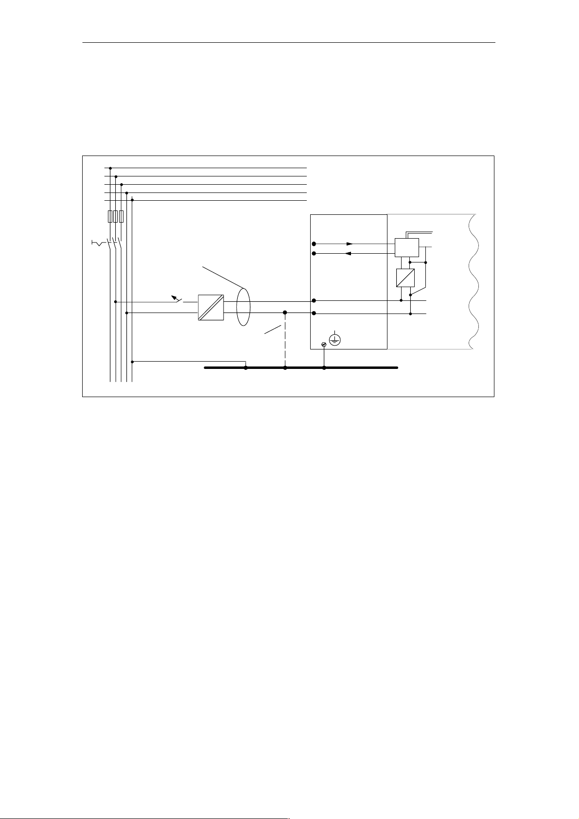
Overall structure of ET 200eco
Figure 3-1 shows the overall structure of an ET 200eco distributed I/O station
((Load supply voltages and grounding concept) with power supply from a TN-S
network.
L1
L2
L3
n
PE
for ET 200eco
with ECOFAST terminal block:
24 VDC NS
AC
DC
PROFIBUS-DP
24 VDC
Low–voltage distribution,
e.g. in a TN-S system (3 400 V)
ET 200eco
Terminal block I/O module
A
B
1 L+
1
M
mP
1M is not connected to PE in installations without grounding.
Grounding bus
Figure 3-1 ET 200eco operation with reference potential bonded to equipotential earth
Data
M
internal
3.3 Electrical structure of the ET 200eco system
Isolated potential
The electrical circuit of an ET 200eco is galvanically separated between:
• 1L+ (electronic circuit/sensor supply):
Potential isolation to PROFIBUS-DP and 2L+ (load voltage supply),except I/O
module 8 DI/8 DO 2 A.
• 2L+ (load voltage supply):
Potential isolation to all other circuit elements execpt I/O module 8 DI/8 DO 2 A.
For I/O module 8 DI/8 DO 2 A, 1M and 2M are interconnected internally.
• PROFIBUS-DP interface:
Potential isolation to other circuit components.
3-4
ET 200eco Distributed I/O Station
A5E00158716-02
 Loading...