

Page 1

Preface, Contents
SIMATIC
ET 200C
Distributed I/O Station
Manual
Configuration
ET 200C Configuration Options
ET 200C Components
Mechanical and Electrical
Installation
Address Assignment and Param-
eterization with COM ET 200
Startup and Test with
COM ET 200
Fault Diagnostics with the
IM 308-B
Fault Diagnostics with the
IM 308-C
Connection of the
ET 200 Handheld
1
2
3
4
5
6
7
8
9
Edition 03
General Technical Specifications
Digital Modules
Analog Modules
Other ET 200C Components
Pin Assignments of the ET 200C
Modules
Type files
Safety-Related Guidelines
Glossary, Index
10
11
12
13
A
B
C
EWA 4NEB 812 6119-02b
Page 2
Safety Guidelines
!
!
!
This manual contains notices which you should observe to ensure your own personal safety,
as well as to protect the product and connected equipment. These notices are highlighted in
the manual by a warning triangle and are marked as follows according to the level of danger:
Danger
indicates that death, severe personal injury or substantial property damage will result if
proper precautions are not taken.
Warning
indicates that death, severe personal injury or substantial property damage can result if
proper precautions are not taken.
Caution
indicates that minor personal injury or property damage can result if proper precautions are
not taken.
Note
draws your attention to particularly important information on the product, handling the
product, or to a particular part of the documentation.
Qualified Personnel
Correct Usage
!
Only qualified personnel should be allowed to install and work on this equipment. Quali-
fied persons are defined as persons who are authorized to commission, to ground, and to tag
circuits, equipment, and systems in accordance with established safety practices and standards.
The device/system may only be set up and operated in conjunction with this manual.
Note the following:
Warning
This device and its components may only be used for the applications described in the catalog or the technical description, and only in connection with devices or components from
other manufacturers which have been approved or recommended by Siemens.
This product can only function correctly and safely if it is transported, stored, set up, and
installed correctly, and operated and maintained as recommended.
SIMATIC and SINEC are registered trademarks of SIEMENS AG.
Copyright
Copyright Siemens AG 1994 All Rights Reserved
The reproduction, transmission or use of this document or its contents
is not permitted without express written authority. Offenders will be
liable for damages. All rights, including rights created by patent grant
or registration of a utility model or design, are reserved.
Exclusion of Liability
We have checked the contents of this manual for agreement with the
hardware and software described. Since deviations cannot be precluded entirely, we cannot guarantee full agreement. However, the data
in this manual is reviewed regularly and any necessary corrections
included in subsequent editions. Suggestions for improvement are
welcomed.
Technical data subject to change.
Page 3
Preface
Purpose
of the Manual
Contents
of the Manual
The information in this manual will enable you to:
install, connect and operate the ET 200C distributed I/O station,
look up the module characteristics and technical data.
This section shows you how the manual is structured.
What is ET 200C?
What configuration options do I
have with ET 200C?
What are the components of ET 200C?
What is involved in mechanical and
electrical installation?
How do I set the address and parameters
with COM ET 200?
How do I perform startup and testing
with COM ET 200?
Errors?
Chap. 1
Chap. 2
Chap. 3
Chap. 4
Chap. 5
Chap. 6
Chap. 7, 8
Scope
of the Manual
ET 200C Distributed I/O Station
EWA 4NEB 812 6119-02b
How do I connect the ET 200 handheld?
T echnical data?
Pin assignment, type files?
This manual covers all the ET 200C modules that can be addressed with the
DP standard bus protocol. Each of these ET 200C modules has an order
number beginning with 6ES7 (See Chapter 10.1).
This manual is applicable to operation of ET 200C in conjunction with
Chap. 9
Chap. 10, 11, 12, 13
Appendix A, B
IM 308-B master interface and COM ET 200
IM 308-C master interface and COM ET 200 Windows.
Operation with the IM 308-B master interface and COM ET 200 is described
in detail in this manual.
iii
Page 4

Preface
Scope
of the Manual
(Continued)
Other Important
Manuals
Quick Access
As regards operation of ET 200C with the IM 308-C master interface and
COM ET 200 Windows, this manual describes only parameterization with
COM ET 200 Windows. See the manual entitled ET 200 Distributed
I/O System (order number 6ES5 998-3ES12) for detailed information on how
to use COM ET 200 Windows and on working with the FB IM 308C standard
function block.
COM ET 200 Windows has an online Help system that provides valuable
assistance for starting up and operating the ET 200C modules.
This manual follows on from the manual entitled ET 200 Distributed
I/O System, which is the master description for the series.
You must read and understand the manual ET 200 Distributed I/O System in
order to use this manual.
A number of features in this manual will help you to obtain quick access to
the information you require:
At the start of the manual you will find a general table of contents, plus a
list of all the illustrations and a list of all the tables in the manual.
On each page throughout the manual, the bold-face headings on the left
summarize the contents of the individual passages.
Standards
Questions
Suggestions
The Appendices are followed by a Glossary containing definitions of the
important terms used in this manual.
The manual closes with a detailed index that you can use to find
information on the topic of your choice.
The ET 200C modules function as DP standard slaves in accordance with the
definitions of DIN E 19245, Parts 1 and 3.
Please address all questions about the ET 200C distributed I/O station to:
Hotline SIMATIC
Erlangen
Phone (+ 49 for Germany) 9131/7-43344
You will find suggestion sheets at the end of the manual. Please note any
suggestions or proposals you may have on these sheets and return them to
use. Your suggestions will help us improve the next edition of the manual.
ET 200C Distributed I/O Station
iv
EWA 4NEB 812 6119-02b
Page 5

Contents
1 Configuration 1-1. . . . . . . . . . . . . . . . . . . . . . . . . . . . . . . . . . . . . . . . . . . . . . . . . . . . . . . .
1.1 What is the ET 200? 1-2. . . . . . . . . . . . . . . . . . . . . . . . . . . . . . . . . . . . . . . . . . .
1.2 What is the ET 200C? 1-3. . . . . . . . . . . . . . . . . . . . . . . . . . . . . . . . . . . . . . . . .
2 ET 200C Configuration Options 2-1. . . . . . . . . . . . . . . . . . . . . . . . . . . . . . . . . . . . . . . .
2.1 Overview of the ET 200C Configuration Options 2-2. . . . . . . . . . . . . . . . . .
2.1.1 Configuration with Power Supply Connector without T Connector 2-4. . . .
2.1.2 Configuration with Power Supply Connector and with T Connectors 2-7.
2.1.3 Configuration using Several Power Supply Connectors 2-10. . . . . . . . . . . .
2.1.4 Configuration without Power Supply Connector 2-12. . . . . . . . . . . . . . . . . . .
2.1.5 Configuration with Programmer Connector 2-16. . . . . . . . . . . . . . . . . . . . . . .
3 ET 200C Components 3-1. . . . . . . . . . . . . . . . . . . . . . . . . . . . . . . . . . . . . . . . . . . . . . . . .
3.1 Digital Input Module ET 200C; DI 8 DC 24V
(6ES7 141-0BF00-0XB0) 3-2. . . . . . . . . . . . . . . . . . . . . . . . . . . . . . . . . . . . . . .
3.2 Digital Output Module ET 200C; DO 8 DC 24V/0.5A
(6ES7 142-0BF00-0XB0) 3-4. . . . . . . . . . . . . . . . . . . . . . . . . . . . . . . . . . . . . . .
3.3 Digital Output Module ET 200C; DO 8 DC 24V/2A
(6ES7 142-0BF10-0XB0) 3-6. . . . . . . . . . . . . . . . . . . . . . . . . . . . . . . . . . . . . . .
3.4 Digital Input/Output Module ET 200C; DI 16/DO 16 DC 24V
(6ES 143-0BL00-0XB0 and 6ES7 143-0BL10-0XB0) 3-8. . . . . . . . . . . . . .
3.5 Analog Input Module ET 200C; AI 4/8 12 Bit
(6ES7 144-0KH00-0XB0) 3-1 1. . . . . . . . . . . . . . . . . . . . . . . . . . . . . . . . . . . . . .
3.6 Analog Input Module ET 200C; AI 4 12 Bit
(6ES7 144-0HF00-0XB0) 3-13. . . . . . . . . . . . . . . . . . . . . . . . . . . . . . . . . . . . . .
3.7 Analog Output Module ET 200C; AO 4 12 Bit
(6ES7 145-0HF00-0XB0) 3-15. . . . . . . . . . . . . . . . . . . . . . . . . . . . . . . . . . . . . .
3.8 T Connector (6ES5 762-2CT11) 3-17. . . . . . . . . . . . . . . . . . . . . . . . . . . . . . . . .
3.9 Power Supply Connector (6ES5 762-2CS11) 3-18. . . . . . . . . . . . . . . . . . . . .
3.10 Programmer Connector (6ES5 762-2CA12) 3-19. . . . . . . . . . . . . . . . . . . . . .
3.1 1 Cables 3-20. . . . . . . . . . . . . . . . . . . . . . . . . . . . . . . . . . . . . . . . . . . . . . . . . . . . . . .
3.12 Terminating Resistor (6ES5 755-2CA11) 3-22. . . . . . . . . . . . . . . . . . . . . . . . .
3.13 Adapter Cable (6ES5 755-8CA11) 3-23. . . . . . . . . . . . . . . . . . . . . . . . . . . . . . .
ET 200C Distributed I/O Station
EWA 4NEB 812 6119-02b
v
Page 6

Contents
4 Mechanical and Electrical Installation 4-1. . . . . . . . . . . . . . . . . . . . . . . . . . . . . . . . . .
4.1 Installation of ET 200C 4-2. . . . . . . . . . . . . . . . . . . . . . . . . . . . . . . . . . . . . . . . .
4.2 Electrical Wiring of the ET 200C Distributed I/O Station 4-3. . . . . . . . . . . .
4.2.1 Grounded Configuration 4-4. . . . . . . . . . . . . . . . . . . . . . . . . . . . . . . . . . . . . . .
4.2.2 Ungrounded Configuration 4-6. . . . . . . . . . . . . . . . . . . . . . . . . . . . . . . . . . . . .
4.3 Wiring of the ET 200C 4-8. . . . . . . . . . . . . . . . . . . . . . . . . . . . . . . . . . . . . . . . .
4.3.1 Wiring of the Bus Connection 4-10. . . . . . . . . . . . . . . . . . . . . . . . . . . . . . . . . . .
4.3.2 Wiring of ET 200C; DI 8 DC 24V (6ES7 141-0BF00-0XB0) 4-13. . . . . . .
4.3.3 Wiring of ET 200C; DO 8 DC 24V/0.5A (6ES7 142-0BF00-0XB0)
and ET 200C; DO 8 DC 24V/2A (6ES7 142-0BF10-0XB0) 4-15. . . . . . .
4.3.4 Wiring of ET 200C; DI 16/DO 16 DC 24V/2A
(6ES7 143-0BL00-0XB0) 4-17. . . . . . . . . . . . . . . . . . . . . . . . . . . . . . . . . . . . . . .
4.3.5 Wiring of ET 200C; DI 16/DO 16 DC 24V/2A
(6ES7 143-0BL10-0XB0) 4-19. . . . . . . . . . . . . . . . . . . . . . . . . . . . . . . . . . . . . . .
4.3.6 Wiring of ET 200C; AI 4/8 12 Bit (6ES7 144-0KH00-0KB0) 4-21. . . . . . .
4.3.7 Wiring of ET 200C; AI 4 12 Bit (6ES7 144-0HF00-0KB0) 4-30. . . . . . . . .
4.3.8 Wiring of ET 200C; AO 4 12 Bit (6ES7 145-0HF00-0KB0) 4-35. . . . . . . .
4.3.9 Wiring of the Load Voltage Supply 4-41. . . . . . . . . . . . . . . . . . . . . . . . . . . . . . .
4.3.10 Wiring of the External Power Supply to the PS Connector 4-42. . . . . . . . . .
4.4 Setting DIL Switches on Analog Modules of ET 200C 4-43. . . . . . . . . . . . . .
4.4.1 Setting the Station Number of Analog Modules by Means of
DIL Switch Block S1 4-44. . . . . . . . . . . . . . . . . . . . . . . . . . . . . . . . . . . . . . . . . . .
4.4.2 Setting the Measurement Type for Analog Module ET 200C;
AI 4/8 12 Bit 4-46. . . . . . . . . . . . . . . . . . . . . . . . . . . . . . . . . . . . . . . . . . . . . . .
4.4.3 Setting Measurement Type for Analog Module ET 200C;
AI 4 12 Bit 4-50. . . . . . . . . . . . . . . . . . . . . . . . . . . . . . . . . . . . . . . . . . . . . . . . .
4.4.4 Setting Connection Mode for Analog Module ET 200C;
AO 4 12 Bit 4-52. . . . . . . . . . . . . . . . . . . . . . . . . . . . . . . . . . . . . . . . . . . . . . . .
5 Address Assignment and Parameterization with COM ET 200 5-1. . . . . . . . . . . .
5.1 Address Assignment with COM ET 200 V4.x 5-2. . . . . . . . . . . . . . . . . . . . . .
5.1.1 Enter Station Number 5-3. . . . . . . . . . . . . . . . . . . . . . . . . . . . . . . . . . . . . . . . . .
5.1.2 Enter Address Area and Station Type 5-5. . . . . . . . . . . . . . . . . . . . . . . . . . . .
5.1.3 Enter Station Name, Addresses and Address Identifier 5-7. . . . . . . . . . . . .
5.1.4 Enter Parameterization Frame with COM ET 200 V4.x 5-12. . . . . . . . . . . . .
6 Startup and Test with COM ET 200 6-1. . . . . . . . . . . . . . . . . . . . . . . . . . . . . . . . . . . . .
6.1 Connecting the Programmer 6-2. . . . . . . . . . . . . . . . . . . . . . . . . . . . . . . . . . . .
6.2 Starting Up and Testing the ET 200C Distributed I/O Station 6-4. . . . . . . .
6.3 Testing the ET 200C Distributed I/O Station 6-6. . . . . . . . . . . . . . . . . . . . . .
7 Fault Diagnostics with the IM 308-B 7-1. . . . . . . . . . . . . . . . . . . . . . . . . . . . . . . . . . . .
7.1 Using LEDs to Diagnose Problems 7-2. . . . . . . . . . . . . . . . . . . . . . . . . . . . . .
7.2 Using COM ET 200 V4.x to Diagnose Problems 7-5. . . . . . . . . . . . . . . . . . .
7.3 Using STEP 5 to Diagnose Problems (Station Diagnosis) 7-7. . . . . . . . . .
7.3.1 “Overview” Diagnostics 7-10. . . . . . . . . . . . . . . . . . . . . . . . . . . . . . . . . . . . . . . .
7.3.2 ”Parameter Assignment and Addressability” Diagnostics 7-12. . . . . . . . . . .
7.3.3 Station Status Diagnostics 7-14. . . . . . . . . . . . . . . . . . . . . . . . . . . . . . . . . . . . .
ET 200C Distributed I/O Station
vi
EWA 4NEB 812 6119-02b
Page 7

7.3.4 Manufacturer Identification Diagnostics 7-17. . . . . . . . . . . . . . . . . . . . . . . . . .
7.3.5 Device-related Diagnostics – Digital ET 200C 7-18. . . . . . . . . . . . . . . . . . . . .
8 Fault Diagnostics with the IM 308-C 8-1. . . . . . . . . . . . . . . . . . . . . . . . . . . . . . . . . . . .
8.1 Using LEDs to Diagnose Problems 8-2. . . . . . . . . . . . . . . . . . . . . . . . . . . . . .
8.2 Using STEP 5 to Diagnose Problems (Station Diagnostics) 8-6. . . . . . . . .
8.2.1 Diagnosing the station status 8-14. . . . . . . . . . . . . . . . . . . . . . . . . . . . . . . . . . .
8.2.2 Diagnosing the Manufacturer Identification 8-17. . . . . . . . . . . . . . . . . . . . . . .
8.2.3 Device-related Diagnostics – Digital ET 200C 8-18. . . . . . . . . . . . . . . . . . . . .
8.2.4 Identification- and Device-related Diagnostics – Analog ET 200C 8-21. . . .
9 Connection of the ET 200 Handheld 9-1. . . . . . . . . . . . . . . . . . . . . . . . . . . . . . . . . . . .
9.1 Connection of the ET 200 Handheld 9-2. . . . . . . . . . . . . . . . . . . . . . . . . . . . .
10 General Technical Specifications 10-1. . . . . . . . . . . . . . . . . . . . . . . . . . . . . . . . . . . . . .
10.1 Overview of Digital and Analog Modules for the ET 200C 10-2. . . . . . . . . . .
10.2 General Technical Specifications 10-3. . . . . . . . . . . . . . . . . . . . . . . . . . . . . . . .
11 Digital Modules 11-1. . . . . . . . . . . . . . . . . . . . . . . . . . . . . . . . . . . . . . . . . . . . . . . . . . . . . .
Contents
11.1 Digital Input Module ET 200C; DI 8 DC 24V
(6ES7 141-0BF00-0BX0) 11-2. . . . . . . . . . . . . . . . . . . . . . . . . . . . . . . . . . . . . . .
11.2 Digital Output Module ET 200C; DO 8 DC 24V/0.5A
(6ES7 142-0BF00-0XB0) 11-6. . . . . . . . . . . . . . . . . . . . . . . . . . . . . . . . . . . . . . .
11.3 Digital Output Module ET 200C; DO 8 DC 24V/2A
(6ES7 142-0BF10-0XB0) 1 1-11. . . . . . . . . . . . . . . . . . . . . . . . . . . . . . . . . . . . . . .
11.4 Digital Input/Output Module ET 200C; DI 16/DO 16 DC 24V/2A
(6ES7 143-0BL00-0XB0 and 6ES7 143-0BL10-0XB0) 11-16. . . . . . . . . . . . .
12 Analog Modules 12-1. . . . . . . . . . . . . . . . . . . . . . . . . . . . . . . . . . . . . . . . . . . . . . . . . . . . . .
12.1 Analog Input Module ET 200C; AI 4/8 12 Bit
(6ES7 144-0KH00-0XB0) 12-2. . . . . . . . . . . . . . . . . . . . . . . . . . . . . . . . . . . . . .
12.2 ET 200C Analog Input Module; AI 4 12 Bit
(6ES7 144-0HF00-0XB0) 12-20. . . . . . . . . . . . . . . . . . . . . . . . . . . . . . . . . . . . . .
12.3 ET 200C Analog Output Module; AO 4 12 Bit
(6ES7 145-0HF00-0XB0) 12-33. . . . . . . . . . . . . . . . . . . . . . . . . . . . . . . . . . . . . .
13 Other ET 200C Components 13-1. . . . . . . . . . . . . . . . . . . . . . . . . . . . . . . . . . . . . . . . . . .
13.1 T Connector (6ES5 762-2CT11) 13-2. . . . . . . . . . . . . . . . . . . . . . . . . . . . . . . . .
13.2 Power Supply Connector (6ES5 762-2CS11) 13-3. . . . . . . . . . . . . . . . . . . . .
13.3 Programmer Connector (6ES5 762-2CA12) 13-5. . . . . . . . . . . . . . . . . . . . . .
13.4 Cables 13-7. . . . . . . . . . . . . . . . . . . . . . . . . . . . . . . . . . . . . . . . . . . . . . . . . . . . . . .
13.5 Terminating Resistor (6ES5 755-2CA11) 13-8. . . . . . . . . . . . . . . . . . . . . . . . .
13.6 Adapter Cable (6ES5 755-8CA11) 13-9. . . . . . . . . . . . . . . . . . . . . . . . . . . . . . .
ET 200C Distributed I/O Station
EWA 4NEB 812 6119-02b
vii
Page 8

Contents
A Pin Assignments of the ET 200C Modules A-1. . . . . . . . . . . . . . . . . . . . . . . . . . . . . .
A.1 Pin Assignments of ET 200C Digital Modules A-2. . . . . . . . . . . . . . . . . . . . .
A.2 Pin Assignments of ET 200C Analog Modules A-5. . . . . . . . . . . . . . . . . . . .
B Type Files B-1. . . . . . . . . . . . . . . . . . . . . . . . . . . . . . . . . . . . . . . . . . . . . . . . . . . . . . . . . . . .
B.1 Type Files, ET 200C Digital Modules for COM ET 200 V4.x B-2. . . . . . . . .
B.1.1 Type File SN8010TD.200: COM ET 200 V4.x - C-8DI DP B-3. . . . . . . . . . .
B.1.2 Type File SN8011TD.200: COM ET 200 V4.x - C-8DO DP B-4. . . . . . . . . .
B.1.3 Type File SN8012TD.200: COM ET 200 V4.x - C-8DO/2A DP B-5. . . . . . .
B.1.4 Type File SN8013TD.200: COM ET 200 V4.x - C-16DI/16DO/2A DP B-6.
B.2 Type Files of ET 200C Analog Modules for COM ET 200 Windows B-7. .
B.2.1 Type File SI800FAD.200: COM ET 200 Windows - C-4/8AI DP B-8. . . . . .
B.2.2 Type File SI800EAD.200: COM ET 200 Windows - C-4AI DP B-13. . . . . . .
B.2.3 Type File SI800DAD.200: COM ET 200 Windows - C-4AO DP B-16. . . . . .
C Safety-Related Guidelines C-1. . . . . . . . . . . . . . . . . . . . . . . . . . . . . . . . . . . . . . . . . . . . .
C.1 Active and Passive Faults in Automation Equipment C-2. . . . . . . . . . . . . . .
C.2 Suggestions for Configuring and Installing a Distributed I/O Station C-3. .
viii
ET 200C Distributed I/O Station
EWA 4NEB 812 6119-02b
Page 9

Figures
1-1 ET 200 Bus Users Described in this Manual 1-2. . . . . . . . . . . . . . . . . . . . . .
1-2 ET 200C Digital and Analog Modules 1-3. . . . . . . . . . . . . . . . . . . . . . . . . . . .
1-3 Other ET 200C Components 1-4. . . . . . . . . . . . . . . . . . . . . . . . . . . . . . . . . . .
2-1 Legend 2-3. . . . . . . . . . . . . . . . . . . . . . . . . . . . . . . . . . . . . . . . . . . . . . . . . . . . . .
2-2 SINEC L2-DP Field Bus and Power Supply Looped Through
at ET 200C Slave Station 2-5. . . . . . . . . . . . . . . . . . . . . . . . . . . . . . . . . . . . . .
2-3 SINEC L2-DP Field Bus and Power Supply Looped Through
with T Connectors 2-8. . . . . . . . . . . . . . . . . . . . . . . . . . . . . . . . . . . . . . . . . . . . .
2-4 Rule for Use of a T Connector 2-9. . . . . . . . . . . . . . . . . . . . . . . . . . . . . . . . . .
2-5 Configuration using Several Power Supply Connectors 2-11. . . . . . . . . . . .
2-6 SINEC L2-DP Field Bus Looped Through with T Connectors –
Individual External Power Supply to Each Slave Station 2-13. . . . . . . . . . . .
2-7 Rules for Use of a T Connector 2-14. . . . . . . . . . . . . . . . . . . . . . . . . . . . . . . . .
2-8 Rules for Current Connection 2-15. . . . . . . . . . . . . . . . . . . . . . . . . . . . . . . . . . .
2-9 Configuration with Programmer Connector 2-16. . . . . . . . . . . . . . . . . . . . . . .
3-1 Digital Input Module ET 200C; DI 8 DC 24V
(6ES7 141-0BF00-0XB0) 3-3. . . . . . . . . . . . . . . . . . . . . . . . . . . . . . . . . . . . . . .
3-2 Digital Output Module ET 200C; DO 8 DC 24V/0.5A
(6ES7 142-0BF00-0XB0) 3-5. . . . . . . . . . . . . . . . . . . . . . . . . . . . . . . . . . . . . . .
3-3 Digital Output Module ET 200C; DO 8 DC 24V/2A
(6ES7 142-0BF10-0XB0) 3-7. . . . . . . . . . . . . . . . . . . . . . . . . . . . . . . . . . . . . . .
3-4 Digital Input/Output Module ET 200C; DI 16/DO 16 DC 24V
with Circular Connector
(6ES7 143-0BL00-0XB0) 3-9. . . . . . . . . . . . . . . . . . . . . . . . . . . . . . . . . . . . . . .
3-5 Digital I/O Module ET 200C; DI 16/DO 16 DC 24 V with
Conduit Thread Glands (6ES7 143-0BL10-0XB0) 3-10. . . . . . . . . . . . . . . . .
3-6 Analog Input Module ET 200C; AI 4/8 12 Bit
(6ES7 144-0KH00-0XB0) 3-12. . . . . . . . . . . . . . . . . . . . . . . . . . . . . . . . . . . . . .
3-7 Analog Input Module ET 200C; AI 4 12 Bit
(6ES7 144-0HF00-0XB0) 3-14. . . . . . . . . . . . . . . . . . . . . . . . . . . . . . . . . . . . . .
3-8 Analog Output Module ET 200C; AO 4 12 Bit
(6ES7 145-0HF00-0XB0) 3-16. . . . . . . . . . . . . . . . . . . . . . . . . . . . . . . . . . . . . .
3-9 T Connector 3-17. . . . . . . . . . . . . . . . . . . . . . . . . . . . . . . . . . . . . . . . . . . . . . . . . .
3-10 Power Supply Connector 3-18. . . . . . . . . . . . . . . . . . . . . . . . . . . . . . . . . . . . . . .
3-11 Programmer Connector 3-19. . . . . . . . . . . . . . . . . . . . . . . . . . . . . . . . . . . . . . . .
3-12 Terminating Resistor 3-22. . . . . . . . . . . . . . . . . . . . . . . . . . . . . . . . . . . . . . . . . . .
3-13 Adapter Cable 3-23. . . . . . . . . . . . . . . . . . . . . . . . . . . . . . . . . . . . . . . . . . . . . . . .
4-1 Grounded Configuration for ET 200C with 24 V DC
Current/Load Voltage Supply 4-5. . . . . . . . . . . . . . . . . . . . . . . . . . . . . . . . . . .
4-2 Ungrounded Configuration for ET 200C 4-7. . . . . . . . . . . . . . . . . . . . . . . . . .
4-3 Bus Connections of the ET 200C Modules 4-10. . . . . . . . . . . . . . . . . . . . . . .
4-4 Sensor Supply Returned to Input without Load 4-14. . . . . . . . . . . . . . . . . . . .
4-5 Sensor Supply Returned to Input with Load 4-14. . . . . . . . . . . . . . . . . . . . . . .
4-6 Output Returned to Input without Load 4-16. . . . . . . . . . . . . . . . . . . . . . . . . . .
4-7 Output Returned to Input with Load 4-16. . . . . . . . . . . . . . . . . . . . . . . . . . . . . .
4-8 Output Returned to Input without Load 4-18. . . . . . . . . . . . . . . . . . . . . . . . . . .
4-9 Output Returned to Input with Load 4-18. . . . . . . . . . . . . . . . . . . . . . . . . . . . . .
4-10 Arrangement of Screw Terminals of ET 200C;
DI 16/DO 16 DC 24V/2A (6ES7 143-0BL10-0XB0) 4-20. . . . . . . . . . . . . .
4-11 Components of the Cable Gland for the Grounding Cable 4-21. . . . . . . . . .
Contents
ET 200C Distributed I/O Station
EWA 4NEB 812 6119-02b
ix
Page 10

Contents
4-12 Arrangement of Screw Terminals and DIL Switches in ET 200C;
AI 4/8 12 Bit 4-23. . . . . . . . . . . . . . . . . . . . . . . . . . . . . . . . . . . . . . . . . . . . . . .
4-13 Connection to ET 200C; AI 4/8 12 Bit of Thermocouples
for Floating Measurement and External Floating Compensation 4-24. . . . .
4-14 Connection to ET 200C; AI 4/8 12 Bit of Thermocouples for
Non-Floating Measurement and External Non-Floating Compensation 4-25
4-15 Connection to ET 200C; AI 4/8 12 Bit of Thermocouples for
Non-Floating Measurement and Internal Compensation 4-26. . . . . . . . . . . .
4-16 Connection to ET 200C; AI 4/8 12 Bit of Resistance Thermometers
(Pt 100) in 2-Wire Circuit for Floating Measurement 4-27. . . . . . . . . . . . . . .
4-17 Connection to ET 200C; AI 4/8 12 Bit of Resistance Thermometers
(Pt 100) in 4-Wire Circuit for Floating Measurement 4-28. . . . . . . . . . . . . . .
4-18 Connection to ET 200C; AI 4/8 12 Bit of Voltage Sensors
in 2-Wire Circuit for Non-Floating Measurement 4-29. . . . . . . . . . . . . . . . . . .
4-19 Components of the Cable Gland for the Grounding Cable 4-30. . . . . . . . . .
4-20 Arrangement of Screw Terminals and DIL Switches in ET 200C;
AI 4 12 Bit 4-32. . . . . . . . . . . . . . . . . . . . . . . . . . . . . . . . . . . . . . . . . . . . . . . . .
4-21 Connection to ET 200C; AI 4 12 Bit of Voltage Sensors
in 2-Wire Circuit for Floating Measurement 4-33. . . . . . . . . . . . . . . . . . . . . . .
4-22 Connection to ET 200C; AI 4 12 Bit of Current Sensors
in 2-Wire Circuit for Floating Measurement 4-34. . . . . . . . . . . . . . . . . . . . . . .
4-23 Components of the Cable Gland for the Grounding Cable 4-35. . . . . . . . . .
4-24 Arrangement of Screw Terminals and DIL Switches in ET 200C;
AO 4 12 Bit 4-37. . . . . . . . . . . . . . . . . . . . . . . . . . . . . . . . . . . . . . . . . . . . . . . .
4-25 Connection of Loads to ET 200C; AO 4 12 Bit, 4-Wire Circuit
for Voltage Output 4-38. . . . . . . . . . . . . . . . . . . . . . . . . . . . . . . . . . . . . . . . . . . . .
4-26 Connection of Loads to ET 200C; AO 4 12 Bit, 2-Wire Circuit
for Voltage Output 4-39. . . . . . . . . . . . . . . . . . . . . . . . . . . . . . . . . . . . . . . . . . . . .
4-27 Connection of Loads to ET 200C; AO 4 12 Bit, 2-Wire Circuit
for Current Output 4-40. . . . . . . . . . . . . . . . . . . . . . . . . . . . . . . . . . . . . . . . . . . . .
4-28 DIL Switch Block in Default Position (As Delivered) 4-44. . . . . . . . . . . . . . . .
4-29 Example of How to Set a Station Number at DIL Switch
Block S1 4-45. . . . . . . . . . . . . . . . . . . . . . . . . . . . . . . . . . . . . . . . . . . . . . . . . . . . .
4-30 Block Diagram of DIL Switches in DIL Switch Block S2 4-47. . . . . . . . . . . . .
4-31 Block Diagram of DIL Switches in DIL Switch Block S4 4-49. . . . . . . . . . . . .
4-32 Block Diagram of DIL Switches in DIL Switch Block S5 4-51. . . . . . . . . . . . .
5-1 “CONFIGURING” Screen (1) 5-4. . . . . . . . . . . . . . . . . . . . . . . . . . . . . . . . . . .
5-2 “CONFIGURING” Screen (2) 5-6. . . . . . . . . . . . . . . . . . . . . . . . . . . . . . . . . . .
5-3 ”CONFIGURING” Screen (3) 5-9. . . . . . . . . . . . . . . . . . . . . . . . . . . . . . . . . . .
5-4 Structure of the Parameterization Frame for ET 200C: Byte 0 5-13. . . . . . .
5-5 Structure of the Parameterization Frame for ET 200C: Byte 1 5-13. . . . . . .
6-1 Connecting the Programmer to the ET 200C 6-2. . . . . . . . . . . . . . . . . . . . . .
6-2 Connecting the Programmer to the SINEC L2-DP Field Bus 6-3. . . . . . . .
6-3 “SYSTEM START-UP/TEST: STATION SELECTED” Screen 6-5. . . . . . . .
6-4 ”SYSTEM START-UP/TEST: STATUS/CONTROL” Screen 6-7. . . . . . . . . .
7-1 ”INDIVIDUAL DIAGNOSTICS” Screen 7-6. . . . . . . . . . . . . . . . . . . . . . . . . . .
7-2 Structure of the Diagnostics Word after Requesting the
Diagnostics ”Overview” 7-1 1. . . . . . . . . . . . . . . . . . . . . . . . . . . . . . . . . . . . . . . .
7-3 Structure of the Diagnostics Word after Requesting the
Diagnostics for ”Parameter Assignment and Addressability” 7-13. . . . . . . .
7-4 Structure of the Diagnostics Word after Requesting the Station
Status (Station Status 1 and Station Status 2) 7-15. . . . . . . . . . . . . . . . . . . .
ET 200C Distributed I/O Station
x
EWA 4NEB 812 6119-02b
Page 11

7-5 Structure of the Diagnostics Word after Requesting the
Station Status (Station Status 3 and Master Address) 7-16. . . . . . . . . . . . . .
7-6 Structure of the Diagnostics Word after Request for Manufacturer
Identification 7-17. . . . . . . . . . . . . . . . . . . . . . . . . . . . . . . . . . . . . . . . . . . . . . . . . .
7-7 Structure of the Diagnostics Word after Requesting the Header
and the Device-related Diagnostics of ET 200C;
DI 16/DO 16 DC 24V/2A 7-19. . . . . . . . . . . . . . . . . . . . . . . . . . . . . . . . . . . . .
7-8 Structure of the Diagnostics Word after Requesting the
Device-related Diagnostics of ET 200C; DI 8 DC 24V, ET 200C;
DO 8 DC 24V/0.5A and ET 200C; DO 8 DC 24V/2A 7-20. . . . . . . . . .
8-1 Diagram Illustrating How Station Diagnostics is Requested
with FB IM308C 8-11. . . . . . . . . . . . . . . . . . . . . . . . . . . . . . . . . . . . . . . . . . . . . . .
8-2 Structure of the Diagnostics Word (Station Status 1 and
Station Status 2) 8-15. . . . . . . . . . . . . . . . . . . . . . . . . . . . . . . . . . . . . . . . . . . . . .
8-3 Structure of the Diagnostics Word ”Station Status 3 and
Master Station Number” 8-16. . . . . . . . . . . . . . . . . . . . . . . . . . . . . . . . . . . . . . . .
8-4 Structure of the ”Manufacturer Identification” Diagnostics Word 8-17. . . . .
8-5 Structure of the Diagnostics Word ”Header and Device-related
Diagnostics” of ET 200C; DI 16/DO 16 DC 24V 8-19. . . . . . . . . . . . . . . . .
8-6 Structure of the Diagnostics Word for ”Device-related Diagnostics”
for ET 200C; DI 8 DC 24V; ET 200C; DO 8 DC 24V/0.5A and
ET 200C; DO 8 DC 24V/2A 8-20. . . . . . . . . . . . . . . . . . . . . . . . . . . . . . . . . .
8-7 Structure of Diagnostics Word for Identification-related Diagnostics
(DW n + 3) for Analog ET 200C Modules 8-24. . . . . . . . . . . . . . . . . . . . . . . . .
8-8 Structure of Diagnostics Word ”Header – Device-related Diagnostics”
(DW n + 4) for Analog ET 200C Modules 8-25. . . . . . . . . . . . . . . . . . . . . . . . .
8-9 Structure of Diagnostics Word ”Device-related Diagnostics –
Diagnostics Alarm” (DW n + 5) for Analog ET 200C Modules 8-25. . . . . . .
8-10 Structure of Diagnostics Word ”Device-related Diagnostics –
Diagnostics Alarm” (DW n + 6) for Analog ET 200C Modules 8-26. . . . . . .
8-11 Structure of Diagnostics Word ”Device-related Diagnostics –
Diagnostics Alarm” (DW n + 7) for Analog ET 200C Modules 8-26. . . . . . .
8-12 Structure of Diagnostics Word ”Device-related Diagnostics –
Diagnostics Alarm” (DW n + 8) for Analog ET 200C Modules 8-27. . . . . . .
8-13 Structure of Diagnostics Word ”Device-related Diagnostics –
Diagnostics Alarm” (DW n + 9) for Analog ET 200C Modules 8-27. . . . . . .
8-14 Structure of Diagnostics Word ”Header and Device-related
Diagnostics – Diagnostics Alarm” (DW n + 10)
for Analog ET 200C Modules 8-28. . . . . . . . . . . . . . . . . . . . . . . . . . . . . . . . . . .
8-15 Structure of Diagnostics Word ”Header and Device-related
Diagnostics – Diagnostics Alarm” (DW n + 12)
for Analog ET 200C Modules 8-29. . . . . . . . . . . . . . . . . . . . . . . . . . . . . . . . . . .
8-16 Structure of Diagnostics Word ”Device-related Diagnostics –
Limit Value Alarm” (DW n + 6) for Analog ET 200C Modules 8-30. . . . . . . .
9-1 Connection of ET 200 Handheld for Configuration with Power Supply
Connector and without T Connector 9-3. . . . . . . . . . . . . . . . . . . . . . . . . . . . .
9-2 Connection of ET 200 Handheld for Configuration with External
Power Supply 9-3. . . . . . . . . . . . . . . . . . . . . . . . . . . . . . . . . . . . . . . . . . . . . . . .
9-3 Connection of the Handheld to the Unassigned Bus Connection
of the ET 200C Station for Configuration with
Power Supply Connector and T Connector 9-4. . . . . . . . . . . . . . . . . . . . . . .
Contents
ET 200C Distributed I/O Station
EWA 4NEB 812 6119-02b
xi
Page 12

Contents
9-4 Connection of the Handheld to the T Connector for Configuration
with Power Supply Connector and T Connector 9-4. . . . . . . . . . . . . . . . . . .
11-1 Digital Input Module ET 200C; DI 8 DC 24V: Block Diagram 11-3. . . . . .
11-2 Digital Input Module ET 200C; DI 8 DC 24 V;
Dimension Drawing 1 1-4. . . . . . . . . . . . . . . . . . . . . . . . . . . . . . . . . . . . . . . . . . .
11-3 Digital Input Module ET 200C; DI 8 DC 24 V; Dimension Drawing
with T Connector and Plug Connectors (with Pin/Socket Inserts) 11-5. . . .
11-4 Digital Output Module ET 200C; DO 8 DC 24V/0.5A:
Block Diagram 11-7. . . . . . . . . . . . . . . . . . . . . . . . . . . . . . . . . . . . . . . . . . . . . . . .
11-5 Digital Output Module ET 200C; DO 8 DC 24 V/0.5A;
Dimension Drawing 1 1-9. . . . . . . . . . . . . . . . . . . . . . . . . . . . . . . . . . . . . . . . . . .
11-6 Digital Output Module ET 200C; DO 8 DC 24 V/0.5A;
Dimension Drawing with T Connector and Plug Connectors
(with Pin/Socket Inserts) 11-10. . . . . . . . . . . . . . . . . . . . . . . . . . . . . . . . . . . . . . .
11-7 Digital Output Module ET 200C; DO 8 DC 24V/2A:
Block Diagram 11-12. . . . . . . . . . . . . . . . . . . . . . . . . . . . . . . . . . . . . . . . . . . . . . . .
11-8 Digital Output Module ET 200C; DO 8 DC 24 V/2A;
Dimension Drawing 1 1-14. . . . . . . . . . . . . . . . . . . . . . . . . . . . . . . . . . . . . . . . . . .
11-9 Digital Output Module ET 200C; DO 8 DC 24 V/2A;
Dimension Drawing with T Connector and Plug Connectors
(with Pin/Socket Inserts) 11-15. . . . . . . . . . . . . . . . . . . . . . . . . . . . . . . . . . . . . . .
11-10 Digital Input/Output Module ET 200C; DI 16/DO 16 DC 24V/2A:
Block Diagram 11-18. . . . . . . . . . . . . . . . . . . . . . . . . . . . . . . . . . . . . . . . . . . . . . . .
11-11 Digital Input/Output Module ET 200C; DI 16/DO 16 DC 24 V/2A
(6ES7 143-0BL00-0XB0); Dimension Drawing 11-20. . . . . . . . . . . . . . . . . . . .
11-12 Digital Input/Output Module ET 200C; DI 16/DO 16 DC 24 V/2A
(6ES7 143-0BL10-0XB0); Dimension Drawing 11-21. . . . . . . . . . . . . . . . . . . .
11-13 Digital Input/Output Module ET 200C; DI 16/DO 16 DC 24 V/2A
(6ES7 143-0BL00-0XB0); Dimension Drawing with T Connector
and Plug Connectors (with Pin/Socket Inserts) 11-22. . . . . . . . . . . . . . . . . . . .
11-14 Digital Input/Output Module ET 200C; DI16/DO 16 DC 24 V/2A
(6ES7 143-0BL10-0XB0); Dimension Drawing with T Connector
and Plug Connectors (with Pin/Socket Inserts) 11-23. . . . . . . . . . . . . . . . . . . .
12-1 ET200C Analog Input Module; AI 4/8 12 Bit: Block Diagram 12-4. . . . . .
12-2 Screw Terminals and Their Assignments in the ET 200C;
AI 4/8 12 Bit 12-4. . . . . . . . . . . . . . . . . . . . . . . . . . . . . . . . . . . . . . . . . . . . . . .
12-3 ET 200C Analog Input Module; AI 4/8 12 Bit:
Dimensional Drawing 12-18. . . . . . . . . . . . . . . . . . . . . . . . . . . . . . . . . . . . . . . . . .
12-4 ET 200C Analog Input Module; AI 4/8 12 Bit:
Dimensional Drawing with T-connector 12-19. . . . . . . . . . . . . . . . . . . . . . . . . . .
12-5 ET200C Analog Input Module; AI 4 12 Bit: Block Diagram 12-21. . . . . . .
12-6 Screw Terminals with Assignments in the ET 200C; AI 4 12 Bit 12-21. . .
12-7 ET 200C Analog Input Module; AI 4 12 Bit:
Dimensional Drawing 12-31. . . . . . . . . . . . . . . . . . . . . . . . . . . . . . . . . . . . . . . . . .
12-8 ET 200C Analog Input Module; AI 4 12 Bit:
Dimensional Drawing with T-connector 12-32. . . . . . . . . . . . . . . . . . . . . . . . . . .
12-9 ET 200C Analog Output Module; AO 4 12 Bit: Block Diagram 12-34. . . .
12-10 Screw Terminals with Assignments in the ET 200C;
AO 4 12 Bit 12-34. . . . . . . . . . . . . . . . . . . . . . . . . . . . . . . . . . . . . . . . . . . . . . . .
xii
ET 200C Distributed I/O Station
EWA 4NEB 812 6119-02b
Page 13

12-11 ET 200C Analog Output Module; AO 4 12 Bit:
Dimensional Drawing 12-42. . . . . . . . . . . . . . . . . . . . . . . . . . . . . . . . . . . . . . . . . .
12-12 ET 200C Analog Output Module; AO 4 12 Bit:
Dimensional Drawing with T-connector 12-43. . . . . . . . . . . . . . . . . . . . . . . . . . .
13-1 Power Supply Connector: Dimension Drawing with Plug Connectors
(with Pin/Socket Insert) 13-3. . . . . . . . . . . . . . . . . . . . . . . . . . . . . . . . . . . . . . . .
13-2 Power Supply Connector: Dimension Drawing 13-4. . . . . . . . . . . . . . . . . . . .
13-3 Programmer Connector: Dimension Drawing with Plug Connectors
(with Pin/Socket Insert) 13-5. . . . . . . . . . . . . . . . . . . . . . . . . . . . . . . . . . . . . . . .
13-4 Programmer Connector: Dimension Drawing 13-6. . . . . . . . . . . . . . . . . . . . .
Contents
ET 200C Distributed I/O Station
EWA 4NEB 812 6119-02b
xiii
Page 14

Contents
T ables
1-1 Maximum baud rates with components of ET 200C 1-6. . . . . . . . . . . . . . . .
1-2 Length of the SINEC L2 Bus Cable in Accordance
with the Baud Rate on the SINEC L2-DP Bus 1-7. . . . . . . . . . . . . . . . . . . . .
2-1 ET 200C Configuration Options 2-2. . . . . . . . . . . . . . . . . . . . . . . . . . . . . . . . .
2-2 Permissible Current Load for Load Voltage Supply 2-6. . . . . . . . . . . . . . . .
2-3 Permissible Current Load for Load Voltage Supply 2-9. . . . . . . . . . . . . . . .
2-4 Length of the Bus Cable, if SINEC L2-DP Field Bus
and Power Supply are Combined in One Cable 2-10. . . . . . . . . . . . . . . . . . .
2-5 Current Consumption of the Digital Modules of ET 200C 2-10. . . . . . . . . . .
2-6 Permissible Current Load for Load Voltage Supply 2-14. . . . . . . . . . . . . . . .
2-7 Length of the Spur Line of the Programmer Connection
in Accordance with the Baud Rate on the SINEC L2-DP Bus 2-17. . . . . . . .
3-1 ET 200C Cables 3-20. . . . . . . . . . . . . . . . . . . . . . . . . . . . . . . . . . . . . . . . . . . . . .
3-2 Order Numbers for Standard Cable Lengths (Core Cross-Sectional
Area 0.75 mm
2
/Max. Current Load 4 A) 3-21. . . . . . . . . . . . . . . . . . . . . . . . . .
3-3 Order Numbers for Standard Cable Lengths (Core Cross-Sectional
Area 0.75 mm
2
/Max. Current Load 4 A) 3-21. . . . . . . . . . . . . . . . . . . . . . . . . .
4-1 Distances between ET 200C Modules and Cable Ducts 4-2. . . . . . . . . . . .
4-2 Order Numbers for Circular Connectors 4-8. . . . . . . . . . . . . . . . . . . . . . . . . .
4-3 Pin Assignment of the Bus Connection where only the SINEC L2-DP
is Connected 4-1 1. . . . . . . . . . . . . . . . . . . . . . . . . . . . . . . . . . . . . . . . . . . . . . . . .
4-4 Pin Assignment of the Bus Connection where only the Power Supply
is Connected 4-12. . . . . . . . . . . . . . . . . . . . . . . . . . . . . . . . . . . . . . . . . . . . . . . . .
4-5 Pin Assignment of the Bus Connection if SINEC L2-DP and
Power Supply are Connected 4-12. . . . . . . . . . . . . . . . . . . . . . . . . . . . . . . . . . .
4-6 Pin Assignment of the Inputs of ET 200C; DI 8 DC 24V
(6ES7 141-0BF00-0XB0) 4-13. . . . . . . . . . . . . . . . . . . . . . . . . . . . . . . . . . . . . . .
4-7 Pin Assignments of the Outputs of ET 200C; DO 8 DC 24V/0.5A
(6ES7 142-0BF00-0XB0) and ET 200C; DO 8 DC 24V/2A
(6ES7 142-0BF10-0XB0) 4-15. . . . . . . . . . . . . . . . . . . . . . . . . . . . . . . . . . . . . . .
4-8 Pin Assignments of the Inputs of ET 200C;
DI 16/DO 16 DC 24V/2A (6ES7 143-0BL00-0XB0) 4-17. . . . . . . . . . . . . .
4-9 Pin Assignments of the Outputs of ET 200C;
DI 16/DO 16 DC 24V/2A (6ES7 143-0BL00-0XB0) 4-17. . . . . . . . . . . . . .
4-10 Connection Assignments of ET 200C; DI 16/DO 16 DC 24V/2A
(6ES7 143-0BL10-0XB0) 4-19. . . . . . . . . . . . . . . . . . . . . . . . . . . . . . . . . . . . . . .
4-11 Connection Assignment of the Inputs of ET 200C; AI 4/8 12 Bit
(6ES7 144-0KH00-0KB0) 4-22. . . . . . . . . . . . . . . . . . . . . . . . . . . . . . . . . . . . . .
4-12 DIL-Switch blocks in the ET 200C; AI 4/8 12 Bit 4-23. . . . . . . . . . . . . . . .
4-13 Connection Assignment of the Inputs of ET 200C; AI 4 12 Bit
(6ES7 144-0HF00-0KB0) 4-31. . . . . . . . . . . . . . . . . . . . . . . . . . . . . . . . . . . . . .
4-14 DIL Switch Blocks in ET 200C; AI 4 12 Bit 4-32. . . . . . . . . . . . . . . . . . . . .
4-15 Pin Assignment, Outputs of ET 200C; AO 4 12 Bit
(6ES7 145-0HF00-0XB0) 4-36. . . . . . . . . . . . . . . . . . . . . . . . . . . . . . . . . . . . . .
4-16 DIL Switch Blocks in ET 200C; AO 4 12 Bit 4-37. . . . . . . . . . . . . . . . . . . .
4-17 Pin Assignment of the Load Voltage Supply 4-41. . . . . . . . . . . . . . . . . . . . . .
4-18 Pin Assignment of the External Power Supply 4-42. . . . . . . . . . . . . . . . . . . . .
4-19 Module-Specific DIL Switch Blocks in ET 200C; AI 4/8 12 Bit 4-46. . . . .
4-20 DIL Switches in DIL Switch Block S2 4-47. . . . . . . . . . . . . . . . . . . . . . . . . . . .
4-21 DIL Switches in DIL Switch Block S3 4-48. . . . . . . . . . . . . . . . . . . . . . . . . . . .
4-22 DIL Switches in DIL Switch Block S4 4-49. . . . . . . . . . . . . . . . . . . . . . . . . . . .
xiv
ET 200C Distributed I/O Station
EWA 4NEB 812 6119-02b
Page 15

4-23 Module-Specific DIL Switch Block in ET 200C; AI 4 12 Bit 4-50. . . . . . . .
4-24 DIL Switches in DIL Switch Block S5 4-51. . . . . . . . . . . . . . . . . . . . . . . . . . . .
4-25 Module-specific DIL-switch block in ET 200C; AO 4 12 Bit 4-52. . . . . . .
4-26 DIL Switches in DIL Switch Block S2 4-53. . . . . . . . . . . . . . . . . . . . . . . . . . . .
5-1 Type File Designations for ET 200C 5-2. . . . . . . . . . . . . . . . . . . . . . . . . . . . .
5-2 Address Identifiers for ET 200C (DP Standard) 5-8. . . . . . . . . . . . . . . . . . .
7-1 Fault Messages through LEDs on the ET 200C; DI 8 DC 24V 7-2. . . .
7-2 Fault Messages through LEDs of the ET 200C;
DO 8 DC 24V/0.5A and ET 200C; DO 8 DC 24V/2A 7-3. . . . . . . . . .
7-3 Fault Messages through LEDs of the ET 200C;
DI 16/DO 16 DC 24V/2A 7-4. . . . . . . . . . . . . . . . . . . . . . . . . . . . . . . . . . . . .
7-4 STEP 5 Diagnostics Facilities 7-7. . . . . . . . . . . . . . . . . . . . . . . . . . . . . . . . . . .
7-5 Structure of the Station Diagnostics for ET 200C 7-8. . . . . . . . . . . . .
7-6 Combination of the Diagnostics ”Overview” and Diagnostics
for ”Parameter Assignment and Addressability” 7-13. . . . . . . . . . . . . . . . . . .
8-1 Fault Messages through LEDs on the ET 200C; DI 8 DC 24V 8-2. . . .
8-2 Fault Messages through LEDs of the ET 200C;
DO 8 DC 24V/0.5A and ET 200C; DO 8 DC 24V/2A 8-3. . . . . . . . . .
8-3 Fault Messages through LEDs of the ET 200C;
DI 16/DO 16 DC 24V/2A 8-4. . . . . . . . . . . . . . . . . . . . . . . . . . . . . . . . . . . . .
8-4 Fault Messages through LEDs of the ET 200C; AI 4/8 12 Bit,
AI 4 12 Bit and AO 4 12 Bit 8-5. . . . . . . . . . . . . . . . . . . . . . . . . . . . . . . .
8-5 STEP 5 Diagnostics Facilities, Operation with IM 308-C 8-6. . . . . . . . . . . .
8-6 Structure of Station Diagnostics for Digital ET 200C Modules 8-7. . . . . . .
8-7 Structure of Station Diagnostics for ET 200C; AI 4/8 12 Bit 8-8. . . . . . .
8-8 Structure of Station Diagnostics for ET 200C; AI 4 12 Bit 8-9. . . . . . . .
8-9 Structure of Station Diagnostics for ET 200C; AO 4 12 Bit 8-10. . . . . . .
8-10 Position of the Diagnostics Data in the Data Block 8-14. . . . . . . . . . . . . . . . .
8-11 Position of Diagnostics Data in Data Block for ET 200C
(digital ET 200C) 8-18. . . . . . . . . . . . . . . . . . . . . . . . . . . . . . . . . . . . . . . . . . . . . .
8-12 Position of Diagnostics Data in Data Block for ET 200C;
AI 4/8 12 Bit 8-21. . . . . . . . . . . . . . . . . . . . . . . . . . . . . . . . . . . . . . . . . . . . . . .
8-13 Position of the Diagnostics Data in the Data Block for ET 200C;
AI 4 12 Bit 8-22. . . . . . . . . . . . . . . . . . . . . . . . . . . . . . . . . . . . . . . . . . . . . . . . .
8-14 Position of the Diagnostics Data in the Data Block for ET 200C;
AO 4 12 Bit 8-23. . . . . . . . . . . . . . . . . . . . . . . . . . . . . . . . . . . . . . . . . . . . . . . .
11-1 Parameters for Digital Input Module ET 200C; DI 8 DC 24 V 11-3. . . . .
11-2 Parameters for Digital Output Module ET 200C;
DO 8 DC 24 V/0.5A 11-8. . . . . . . . . . . . . . . . . . . . . . . . . . . . . . . . . . . . . . . . .
11-3 Parameters for Digital Output Module ET 200C;
DO 8 DC 24 V/2A 11-13. . . . . . . . . . . . . . . . . . . . . . . . . . . . . . . . . . . . . . . . . .
11-4 Parameters for Digital Input/Output Module ET 200C;
DI 16/DO 16 DC 24 V/2A 11-19. . . . . . . . . . . . . . . . . . . . . . . . . . . . . . . . . . . .
12-1 Parameters for ET 200C Analog Input Module; AI 4/8 12 Bit 12-5. . . . . .
12-2 Parameters for ET 200C Analog Input Module; AI 4/8 12 Bit:
Range of Values, Bytes 25 to 28 12-6. . . . . . . . . . . . . . . . . . . . . . . . . . . . . . . .
12-3 Presentation of an Analog Input Value as Bit Pattern for SIMATIC S5
with ET 200C; AI 4/8 12 Bit 12-8. . . . . . . . . . . . . . . . . . . . . . . . . . . . . . . . . .
12-4 Description of Bit for ET 200C; AI 4/8 12 Bit 12-8. . . . . . . . . . . . . . . . . . . .
12-5 Digitized Measured Values for ET 200C; AI 4/8 12 Bit
(Measuring Ranges:
" 80 mV, " 250 mV, " 500 mV and
" 1000 mV) 12-9. . . . . . . . . . . . . . . . . . . . . . . . . . . . . . . . . . . . . . . . . . . . . . . . . .
Contents
ET 200C Distributed I/O Station
EWA 4NEB 812 6119-02b
xv
Page 16

Contents
12-6 Digitized Measured Values for ET 200C; AI 4/8 12 Bit with
Resistance Sensors 12-10. . . . . . . . . . . . . . . . . . . . . . . . . . . . . . . . . . . . . . . . . . .
12-7 Digitized Measured Values for ET 200C; AI 4/8 12 Bit with
Linearization; Type K Thermocouple (Nickel-Chromium/
Nickel-Aluminum, to IEC 584) 12-11. . . . . . . . . . . . . . . . . . . . . . . . . . . . . . . . . . .
12-8 Digitized Measured Values for ET 200C; AI 4/8 12 Bit with
Linearization; Type J Thermocouple (Iron/Copper-Nickel
(Constantan), to IEC 584) 12-12. . . . . . . . . . . . . . . . . . . . . . . . . . . . . . . . . . . . . .
12-9 Digitized Measured Values for ET 200C; AI 4/8 12 Bit
with Linearization; Type L Thermocouple (Iron/Copper-Nickel
(Constantan), to DIN 43710) 12-13. . . . . . . . . . . . . . . . . . . . . . . . . . . . . . . . . . . .
12-10 Presentation of an Analog Input Value as Bit Pattern for SIMATIC S7
with ET 200C; AI 4/8 12 Bit 12-14. . . . . . . . . . . . . . . . . . . . . . . . . . . . . . . . . .
12-11 Digitized Measured Values for ET 200C; AI 4/8 12 Bit
(Measuring Ranges: " 80 mV, " 250 mV, " 500 mV and
" 1000 mV) 12-14. . . . . . . . . . . . . . . . . . . . . . . . . . . . . . . . . . . . . . . . . . . . . . . . . .
12-12 Digitized Measured Values for ET 200C; AI 4/8 12 Bit for Pt 100
Resistance Sensors 12-15. . . . . . . . . . . . . . . . . . . . . . . . . . . . . . . . . . . . . . . . . . .
12-13 Digitized Measured Values for ET 200C; AI 4/8 12 Bit for Type K
Thermocouple 12-15. . . . . . . . . . . . . . . . . . . . . . . . . . . . . . . . . . . . . . . . . . . . . . . .
12-14 Digitized Measured Values for ET 200C; AI 4/8 12 Bit for Type N
Thermocouple 12-16. . . . . . . . . . . . . . . . . . . . . . . . . . . . . . . . . . . . . . . . . . . . . . . .
12-15 Digitized Measured Values for ET 200C; AI 4/8 12 Bit for Type J
Thermocouple 12-16. . . . . . . . . . . . . . . . . . . . . . . . . . . . . . . . . . . . . . . . . . . . . . . .
12-16 Digitized Measured Values for ET 200C; AI 4/8 12 Bit for Type E
Thermocouple 12-17. . . . . . . . . . . . . . . . . . . . . . . . . . . . . . . . . . . . . . . . . . . . . . . .
12-17 Parameters for ET 200C Analog Input Module; AI 4 12 Bit 12-22. . . . . . .
12-18 Presentation of an Analog Input Value as Bit Pattern for ET 200C;
AI 4 12 Bit 12-24. . . . . . . . . . . . . . . . . . . . . . . . . . . . . . . . . . . . . . . . . . . . . . . . .
12-19 Description of bits for ET 200C; AI 4 12 Bit 12-24. . . . . . . . . . . . . . . . . . . . .
12-20 Digitized Measured Values for ET 200C; AI 4 12 Bit
(Measuring Ranges: " 1.25 V, " 2.5 V, " 5 V, " 10 V) 12-25. . . . . . . . . . .
12-21 Digitized Measured Values for ET 200C; AI 4 12 Bit
(Measuring Range: " 20 mA) 12-26. . . . . . . . . . . . . . . . . . . . . . . . . . . . . . . . . .
12-22 Digitized Measured Values for ET 200C; AI 4 12 Bit
(Measuring Range: 0 ... 20 mA) 12-27. . . . . . . . . . . . . . . . . . . . . . . . . . . . . . . . .
12-23 Digitized Measured Values for ET 200C; AI 4 12 Bit
(Measuring Range: 4 ... 20 mA) 12-27. . . . . . . . . . . . . . . . . . . . . . . . . . . . . . . . .
12-24 Presentation of an Analog Input Value as Bit Pattern for SIMATIC S7
with ET 200C; AI 4 12 Bit 12-28. . . . . . . . . . . . . . . . . . . . . . . . . . . . . . . . . . . .
12-25 Digitized Measured Values for ET 200C; AI 4 12 Bit
(Measuring Ranges: " 1.25 V, " 2.5 V, " 5 V and " 10 V) 12-28. . . . . . .
12-26 Digitized Measured Values for ET 200C;
AI 4 12 Bit (Measuring Range: " 20 mA) 12-29. . . . . . . . . . . . . . . . . . . . . .
12-27 Digitized Measured Values for ET 200C; AI 4 12 Bit
(Measuring Ranges: 0 to 20 mA and 4 to 20 mA) 12-30. . . . . . . . . . . . . . . . . .
12-28 Parameters for ET 200C Analog Output Module; AO 4 12 Bit 12-35. . . . .
12-29 Substitute Value Output of ET 200C; AO 4 12 Bit on Interruption
in Communication 12-36. . . . . . . . . . . . . . . . . . . . . . . . . . . . . . . . . . . . . . . . . . . . .
12-30 Presentation of an Analog Input Value as Bit Pattern for ET 200C;
AO 4 12 Bit 12-37. . . . . . . . . . . . . . . . . . . . . . . . . . . . . . . . . . . . . . . . . . . . . . . .
12-31 Description of bits for ET 200C; AO 4 12 Bit 12-37. . . . . . . . . . . . . . . . . . . .
xvi
ET 200C Distributed I/O Station
EWA 4NEB 812 6119-02b
Page 17

12-32 Analog Output Signals of ET 200C; AO 4 12 Bit
(Ranges of Values: " 10 V, 0 ... 10 V, " 20 mA, 0 ... 20 mA,
4 ... 20 mA) 12-38. . . . . . . . . . . . . . . . . . . . . . . . . . . . . . . . . . . . . . . . . . . . . . . . . .
12-33 Presentation of an Analog Input Value as Bit Pattern for SIMATIC S7
with ET 200C; AO 4 12 Bit 12-39. . . . . . . . . . . . . . . . . . . . . . . . . . . . . . . . . . .
12-34 Digitized Measured Values for ET 200C; AO 4 12 Bit
(Output Ranges: " 20 mA, 0 to 20 mA and 4 to 20 mA) 12-40. . . . . . . . . . . .
12-35 Digitized Measured Values for ET 200C; AO 4 12 Bit
(Output Ranges: 0 to 10 V and " 10 V) 12-41. . . . . . . . . . . . . . . . . . . . . . . . . .
A-1 Pin Assignment of Bus Connector for ET 200 C Digital Modules,
only SINEC L2-DP Connected A-2. . . . . . . . . . . . . . . . . . . . . . . . . . . . . . . . . .
A-2 Pin Assignment of Bus Connector for ET 200C Digital Modules,
only Separate Power Supply Connected A-2. . . . . . . . . . . . . . . . . . . . . . . . .
A-3 Pin Assignment of Bus Connector for ET 200C Digital Modules,
SINEC L2-DP and Power Supply Combined in a Common Cable A-2. . . .
A-4 Pin Assignment, Inputs of ET 200C; DI 8 DC 24V and ET 200C;
DI 16/DO 16 DC 24V/2A (6ES7 143-0BL00-0BX0) A-3. . . . . . . . . . . . . .
A-5 Pin Assignment, Outputs of ET 200C; DO 8 DC 24V/0.5A,
ET 200C; DO 8 DC 24V/2A and ET 200C;
DI16/DO16 DC 24V/2A (6ES7 143- 0BL00-0XB0) A-3. . . . . . . . . . . . . .
A-6 Pin Assignment, Inputs and Outputs of ET 200C;
DI 16/DO 16 DC 24V/2A (6ES7 143-0BL10-0XB0) A-3. . . . . . . . . . . . . .
A-7 Pin Assignment for Load Voltage Supply, ET 200C Modules
with Outputs A-4. . . . . . . . . . . . . . . . . . . . . . . . . . . . . . . . . . . . . . . . . . . . . . . . . .
A-8 Pin Assignment, External Power Supply at PSU Feed A-4. . . . . . . . . . . . . .
A-9 Pin Assignment of Bus Connector for ET 200C Analog Modules,
only SINEC L2-DP Connected A-5. . . . . . . . . . . . . . . . . . . . . . . . . . . . . . . . . .
A-10 Pin Assignment of Bus Connector for ET 200C Analog Modules,
only Separate Power Supply Connected A-5. . . . . . . . . . . . . . . . . . . . . . . . .
A-11 Pin Assignment of Bus Connector for ET 200C Analog Modules,
SINEC L2-DP and Power Supply Combined in a Common Cable A-5. . . .
A-12 Pin Assignment, Inputs of ET 200C; AI 4/8 12 Bit
(6ES7 144-0KH00-0XB0) A-6. . . . . . . . . . . . . . . . . . . . . . . . . . . . . . . . . . . . . .
A-13 Pin Assignment, Inputs of ET 200C; AI 4 12 Bit
(6ES7 144-0HF00-0XB0) A-7. . . . . . . . . . . . . . . . . . . . . . . . . . . . . . . . . . . . . .
A-14 Pin Assignment, Outputs of ET 200C; AO 4 12 Bit
(6ES7 145-0HF00-0XB0) A-8. . . . . . . . . . . . . . . . . . . . . . . . . . . . . . . . . . . . . .
B-1 Designations of Type Files for ET 200C Digital Modules B-2. . . . . . . . . . . .
B-2 Designations of Type Files for ET 200C Analog Modules B-7. . . . . . . . . . .
Contents
ET 200C Distributed I/O Station
EWA 4NEB 812 6119-02b
xvii
Page 18

Contents
xviii
ET 200C Distributed I/O Station
EWA 4NEB 812 6119-02b
Page 19

Configuration
1
In this Chapter
This chapter ”Configuration” provides you with information on
the position of the ET 200C distributed I/O station in the distributed I/O
system and
the components of the ET 200C.
ET 200C Distributed I/O Station
EWA 4NEB 812 6119-02b
1-1
Page 20

Configuration
1.1 What is the ET 200?
Definition
Stations Described
in this Manual
The distributed I/O system ET 200 is based on the PROFIBUS standard
(DIN 19245, Part 1) and the PROFIBUS-DP draft standard (DIN 19245,
Part 3).
At SIEMENS, the PROFIBUS is called SINEC L2.
The field bus on which the ET 200 distributed I/O system is based, is a variant
of SINEC L2 called SINEC L2-DP. This version is designed for communication
with the distributed I/O at extremely short response times.
The distributed I/O system comprises active and passive stations, the
SINEC L2-DP field bus and the SINEC L2 network components. The
distributed I/O station is a slave station.
+
IM 308-B
IM 308-C
ET 200CET 200B
ET 200U
SINEC L2-DP Field Bus
(2-wire or Fiber-Optic Cable)
Figure 1-1 ET 200 Bus Users Described in this Manual
Other field
devices
1-2
ET 200C Distributed I/O Station
EWA 4NEB 812 6119-02b
Page 21
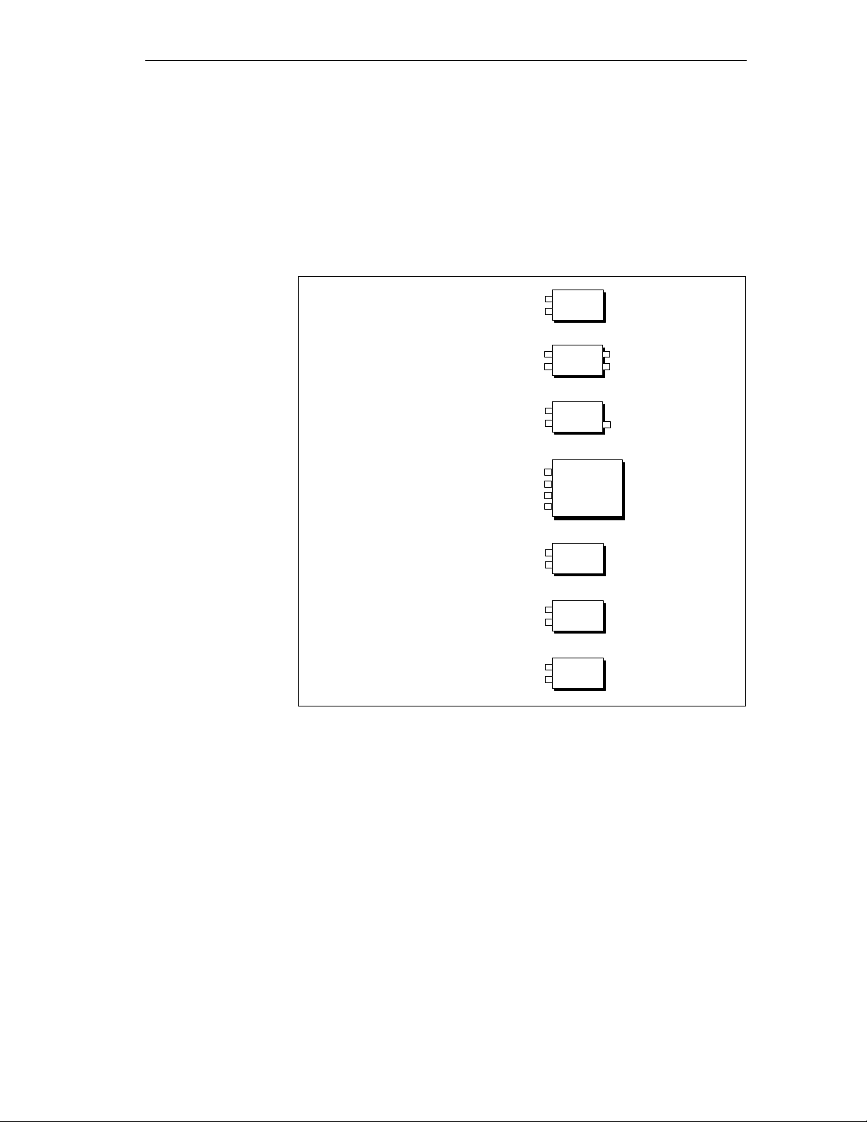
1.2 What is the ET 200C?
Configuration
Range of Modules
The ET 200C Distributed I/O Station is part of the ET 200 Distributed I/O
System.
The ET 200C digital and analog modules each form a slave station.
Digital Input Module
DI 8 DC 24V
Digital Output Module
DO 8 DC 24V/0,5A
Digital Output Module
DO 8 DC 24V/2A
8DI
8DO
8DO/2A
Digital Input/Output Module
DI 16/DO 16 DC 24V/2A
Analog Input Module
AI 4/8 12 Bit
Analog Input Module
AI 4 12 Bit
16DI/16DO
4/8AI
4AI
ET 200C Distributed I/O Station
EWA 4NEB 812 6119-02b
Analog Output Module
AO 4 12 Bit
Figure 1-2 ET 200C Digital and Analog Modules
4AO
1-3
Page 22
Configuration
What is the ET 200C?, Continued
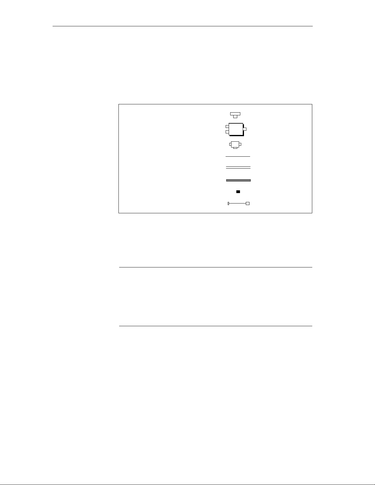
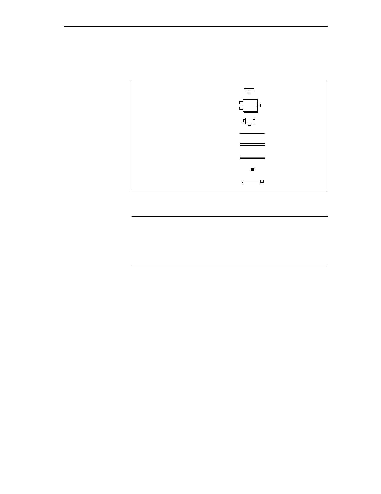
Other Components
Operating ET 200C
ET 200C also includes other components. Not all components may be necessary for operation:
T-Connector
Power Supply Connector
(PS Conn.)
Programmer Connector
Bus Cable
Power Supply Cable
Combined Bus/
Power-Supply Cable
SV-
SV
Einsp.
PG
2-core
3-core
5-core
Terminating Resistor
Adapter Cable
Figure 1-3 Other ET 200C Components
All ET 200C components can be addressed under the DP standard bus protocol.
Note
ET 200C can be operated with the following master interface modules and
versions of COM ET 200:
IM 308-B (revision level 5 or higher) and COM ET 200 (V4.0 or later,
see Chapters 5 and 6), only in conjunction with ET 200C digital modules
IM 308-C (revision level 1 or higher) and COM ET 200 Windows
1-4
ET 200C Distributed I/O Station
EWA 4NEB 812 6119-02b
Page 23

Configuration
Characteristics of
the ET 200C
The ET 200C Distributed I/O Station has the following characteristics:
Degree of protection IP 66/IP 67
All components of the ET 200C (excluding adapter cables) are designed
with degree of protection IP 66 and 67. However, IP 66 and IP 67 are only
ensured if the installation rules in Section 4.1 are observed.
Compact design
ET 200C is ideal for applications where space is at a premium. A digital
input module with T connector, for example, measures only
289 129 57 mm. An analog module with T connector measures a
mere 289 101 57 mm.
Connections
– Digital inputs and/or digital outputs, analog inputs or analog outputs
– Protective conductor connection for each input/output (digital modules
only)
– 2-wire and 3-wire proximity switches can be connected
Electrical isolation between the SINEC L2-DP field bus and the process
side of the ET 200C modules.
Direct connection of programmer or ET 200 handheld possible (with
adapter cable and programmer with programmer interface module
CP5410-S5DOS/ST)
– For setting the station number (digital modules require ET 200
handheld; analog modules by means of internal DIL switches or the
ET 200 handheld)
– For testing and startup
– Diagnostics
Diagnostics of the inputs/outputs for the following types of fault (can be
switched off with COM ET 200)
– Short-circuit/overload of the sensor supply or outputs
– Wire break in sensor supply (except in DI 16/DO 16 DC 24V/2A)
or at the outputs
– Load voltage of the outputs (digital modules only)
A diagnostic report on defective inputs/outputs can also be output via the
IM 308-B master interface module.
ET 200C Distributed I/O Station
EWA 4NEB 812 6119-02b
1-5
Page 24
Configuration
Characteristics of
the ET 200C
(Continued)
The digital modules have the following LEDs
– RUN
– BF (bus fault)
– DIA (diagnostics of the inputs/outputs or undervoltage of the outputs)
–U
in DO 8 DC 24V/0.5A and DO 8 DC 24V/2A or UL1, UL2 in
L
DI 16/DO 16 DC 24V/2A (load voltage supply of the outputs)
– Status of the inputs/outputs or individual diagnostics
The analog modules have the following LEDs
– RUN
– BF (bus fault)
– DIA (diagnostics of the inputs/outputs)
High data throughput:
The bus accommodates, for example, the IM 308-C master interface and
ten ET 200C; DI 16/DO 16 DC 24V/2A distributed I/O stations each
with 2-byte inputs/outputs. The baud rate is 12 Mbaud. The reaction time
for a complete data cycle is thus 0.45 ms.
The reaction time t
A, B, T
= master-dependent constants
byte
for a data cycle is calculated as follows:
DP
t
= A
DP
+ (B + (number of I/O bytes T
+ (B + (number of I/O bytes T
+ ...
+ (B + (number of I/O bytes T
)) [slave 1]
byte
)) [slave 2]
byte
)) [slave n]
byte
1-6
Table 1-1 Maximum baud rates with components of ET 200C
With master interface ET 200C components Maximum baud rate
IM 308-B All digital modules 1.500 kbaud
IM 308-C All digital modules 12.000 kbaud
IM 308-C All digital modules 1.500 kbaud
ET 200C Distributed I/O Station
EWA 4NEB 812 6119-02b
Page 25
Configuration
Length of the SINEC L2 bus cable
The following values apply for the SINEC L2 bus cable in accordance
with the baud rate on the bus when configuring the ET 200C.
Table 1-2 Length of the SINEC L2 Bus Cable in Accordance with the Baud Rate on
the SINEC L2-DP Bus
Baud rate Max. length of bus cable
< 500 kbaud 500 m/segment
500 kbaud 400 m/segment
1500 kbaud 200 m/segment
> 1500 kbaud 100 m/segment
ET 200C Distributed I/O Station
EWA 4NEB 812 6119-02b
1-7
Page 26

Configuration
1-8
ET 200C Distributed I/O Station
EWA 4NEB 812 6119-02b
Page 27

ET 200C Configuration Options
This chapter describes the configuration options offered to you by ET 200C.In this Chapter
2
ET 200C Distributed I/O Station
EWA 4NEB 812 6119-02b
2-1
Page 28

pp y
ET 200C Configuration Options
2.1 Overview of the ET 200C Configuration Options
Configuration
Options
The table below contains the various configuration options made available by
ET 200C.
Table 2-1 ET 200C Configuration Options
PS connector Configuration Described in
Configuration
with power supply
connector
Configuration with power supply
connector and without T connector
Configuration with power supply
Section 2.1.1
Section 2.1.2
connector and with T connector
Configuration with several power
Section 2.1.3
supply connectors (the level of
expansion with one power supply
connector is limited)
Configuration with programmer
Section 2.1.5
connector
Configuration
without power
Configuration without power
supply connector
Section 2.1.4
supply connector
(each module has
a separate power
Configuration with programmer
connector
Section 2.1.5
supply)
2-2
ET 200C Distributed I/O Station
EWA 4NEB 812 6119-02b
Page 29
ET 200C Configuration Options
Legend for the
Following
Sections
The ET 200C configuration options are described in the following sections
by means of diagrams which are based on the following legend:
T Connector
PS
Power Supply Connector
Programmer Connector
Bus Cable incl. PS Cable
Bus Cable
PS Cable
SV
conn.
PG
2-core
3-core (see note)
5-core
Terminating Resistor
Adapter Cable
Figure 2-1 Legend
Note
You will require a 3-core cable for the load voltage supply and the separate
power supply connectors of the digital modules. You can, however, also use
the prefabricated, 5-core cable from Siemens for the load voltage. T wo of
the conductors will then not be used in this case (see Section 3.11).
ET 200C Distributed I/O Station
EWA 4NEB 812 6119-02b
2-3
Page 30

ET 200C Configuration Options
2.1.1 Configuration with Power Supply Connector without T Connector
Definition
Advantage
Constraint
Cables
In a configuration with looped field bus and power supply, the individual
modules are connected directly to the field bus.
The power supply is combined with the field bus in a single cable via the
power supply connector.
You do not need a T connector.
The power supply is run over the bus cable, i.e. no external power supply is
required for the slave station.
If a slave station is disconnected from the bus, the “Bus traffic” is interrupted
for slave stations located further down the line.
Since there is then no terminating resistor available, bus traffic might be disturbed for slave stations still connected to the bus.
The level of expansion using one power supply connector is limited
(see Section 2.1.3).
Different types of cable can be used for the various configurations:
Read Section 3.11 if you wish to use prefabricated cables from Siemens.
Read Section 4.3 if you wish to prepare the cables yourself.
2-4
ET 200C Distributed I/O Station
EWA 4NEB 812 6119-02b
Page 31

ET 200C Configuration Options
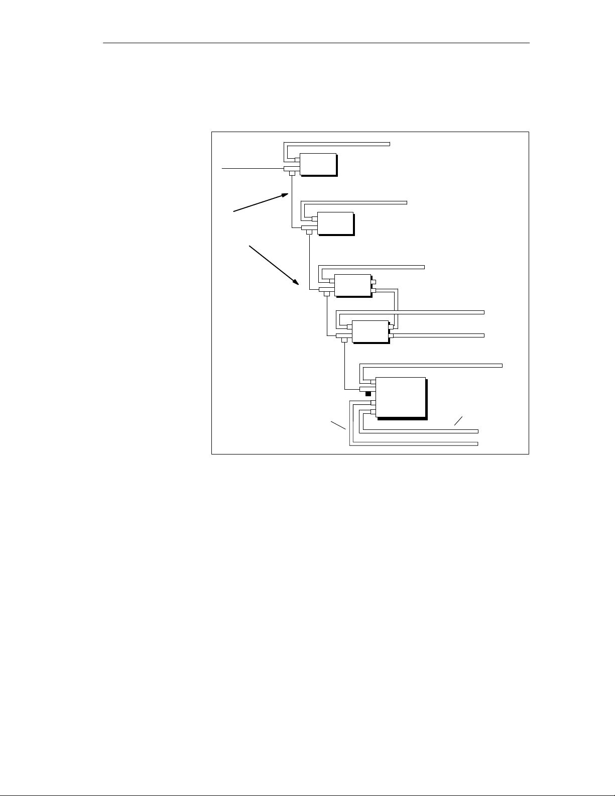
Configuration
A possible configuration with power supply connector and without
T connector can be seen in Fig. 2-2:
External Power
Supply
SINEC L2-DP
1)
No separate load voltage
supply is necessary for
analog output modules
PS
SV
conn.
4/8AI
1)
4AO
8DO
Load Voltage
Supply Looped On
8DO
External Load
V oltage Supply
16DI/16DO
Load V oltage
Supply for
Channel Group Q0
Load V oltage Supply for Channel
Group Q1
ET 200C Distributed I/O Station
EWA 4NEB 812 6119-02b
Figure 2-2 SINEC L2-DP Field Bus and Power Supply Looped Through at
ET 200C Slave Station
2-5
Page 32

ET 200C Configuration Options
Configuration with Power Supply Connector without T Connector,
Continued
Rules for the
External Load
Voltage Supply
The maximum permissible current for the external load voltage supply is
limited:
Table 2-2 Permissible Current Load for Load Voltage Supply
Digital module T otal permissible curr ent load
ET 200C;
max. 4 A
DO 8 DC 24V/0.5A
ET 200C;
DO 8 DC 24V/2A
Ambient temperature:
–25 ... +25 C max. 10 A
+26 ... +40 C max. 8 A
+41 ... +60 C max. 4 A
ET 200C;
DI 16/DO 16 DC 24V/2A
(outputs in groups of 4)
Ambient temperature:
–25 ... +25 C max. 3.5 A per group of 4
+26 ... +40 C max. 2.5 A per group of 4
+41 ... +60 C max. 1.5 A per group of 4
Note
An external load voltage supply can only be looped via the digital output
module DO 8 DC 24V/0.5A until the maximum current of 4 A is reached.
The maximum current load of 4 A is not protected by means of a fuse in the
module.
2-6
ET 200C Distributed I/O Station
EWA 4NEB 812 6119-02b
Page 33

ET 200C Configuration Options
2.1.2 Configuration with Power Supply Connector and with T Connectors
Definition
Advantage
Constraint
Cables
In a configuration with power supply connector and T connectors, the individual modules are connected to the field bus by T connectors.
The power supply is combined with the field bus in a single cable via the
power supply connector.
A slave station can be disconnected at any time from the bus without interrupting the “Bus traffic” for the remaining slave stations.
The power supply is fed over the bus cable, i.e. no external power supply is
required for the slave stations.
The level of expansion with one power supply connector is limited
(see Section 2.1.3).
Different types of cable can be used for the various configurations:
Read Section 3.11 if you wish to use prefabricated cables from Siemens.
Read Section 4.3 if you wish to prepare the cables yourself.
ET 200C Distributed I/O Station
EWA 4NEB 812 6119-02b
2-7
Page 34

ET 200C Configuration Options
Configuration with Power Supply Connector and with T Connectors,
Continued
Configuration
A possible configuration with power supply connector and with T connector
can be seen in Fig. 2-3:
External Power
Supply
PS
SV
conn.
SINEC L2-DP
1)
No separate load voltage
supply is necessary for
analog output modules
4AI
1)
4AO
8DO
8DO
16DI/16DO
Load V oltage Supply for
Channel Group Q1
Load Voltage Supply
Looped On
External Load
V oltage Supply
Load V oltage
Supply for Channel Group Q0
2-8
Figure 2-3 SINEC L2-DP Field Bus and Power Supply Looped Through with
T Connectors
ET 200C Distributed I/O Station
EWA 4NEB 812 6119-02b
Page 35

ET 200C Configuration Options
Rules for the
External Load
Voltage Supply
The maximum permissible current for the external load voltage supply is
limited:
Table 2-3 Permissible Current Load for Load Voltage Supply
Digital module Total permissible current load
ET 200C;
max. 4 A
DO 8 DC 24V/0.5A
ET 200C;
DO 8 DC 24V/2A
Ambient temperature:
–25 ... +25 C max. 10 A
+26 ... +40 C max. 8 A
+41 ... +60 C max. 4 A
ET 200C;
DI 16/DO 16 DC 24V/2A
(outputs in groups of 4)
Ambient temperature:
–25 ... +25 C max. 3.5 A per group of 4
+26 ... +40 C max. 2.5 A per group of 4
+41 ... +60 C max. 1.5 A per group of 4
Note
An external load voltage supply can only be looped via the digital output
module DO 8 DC 24V/0.5A until the maximum current of 4 A is reached.
The maximum current load of 4 A is not protected by means of a fuse in the
module.
Rules for the
T Connector
Spur lines are not permitted on the ET 200C except for the programmer or
the ET 200 handheld. This means that the 12-pin plug of the T connector is
always secured directly to the bus connection of a module.
8DI 8DI
Without Spur Line With Spur Line
Figure 2-4 Rule for Use of a T Connector
ET 200C Distributed I/O Station
EWA 4NEB 812 6119-02b
2-9
Page 36

ET 200C Configuration Options
2.1.3 Configuration using Several Power Supply Connectors
Constraint when
Using One Power
Supply Connector
In the configurations using a power supply connector (see Sections 2.1.2 and
2.1.1), the power supply is fed over the bus cable.
This design is limited by the following factors:
If the power supply and the SINEC L2-DP field bus are combined in one
cable, the following values apply for the length of the bus cable between
the power supply connector and the last slave station connected:
Table 2-4 Length of the Bus Cable, if SINEC L2-DP Field Bus and Power Supply
are Combined in One Cable
Current load Max. cable length
< 1 A 80 m
< 2 A 40 m
< 4 A 20 m
A maximum of 4 A can be looped via the power supply connector. The
current consumption of the digital modules limits the number of digital
modules that can be connected.
Table 2-5 Current Consumption of the Digital Modules of ET 200C
Digital module Current consumption comprises Current
consumption
ET 200C; DI 8 DC 24V Power supply for internal logic
typ. 135 mA
and
Sensor supply
application-specific
(see Section 4.3.2)
ET 200C; DO 8 DC 24V/0.5A Power supply for internal logic typ. 90 mA
ET 200C; DO 8 DC 24V/2A Power supply for internal logic typ. 90 mA
ET 200C; DI16/DO16 DC 24V/2A Power supply for internal logic
typ. 90 mA
and
Sensor supply
application-specific
(see Section 4.3.2)
ET 200C; AI 4/8 12 Bit Power supply for internal logic typ. 80 mA
ET 200C; AI 4 12 Bit Power supply for internal logic typ. 130 mA/ 24 V
ET 200C; AI 4 12 Bit Power supply for internal logic typ. 120 mA
2-10
ET 200C Distributed I/O Station
EWA 4NEB 812 6119-02b
Page 37

ET 200C Configuration Options
Remedy
You are planning several power supply connectors per segment. A possible
configuration with several power supply connectors can be seen in Fig. 2-5.
External
Power Supply
SINEC L2-DP
External
Power Supply
1
In this case, you can use a 2 or 5-core cable. The 2 “left” connections for
“External power supply” and “SINEC L2-DP” are not jumpered!
PS
SV
conn.
SINEC L2-DP
PS
SV
conn.
8DI
1
8DI
8DO
External Load
8DO
V oltage Supply
Figure 2-5 Configuration using Several Power Supply Connectors
ET 200C Distributed I/O Station
EWA 4NEB 812 6119-02b
2-11
Page 38

ET 200C Configuration Options
2.1.4 Configuration without Power Supply Connector
Definition
Advantage
Cables
In a configuration with a separate power supply each slave station is supplied
individually with current. This current supply may not be fed over the bus
cable.
The T connector for connecting SINEC L2-DP is essential for being able to
loop the SINEC L2-DP field bus.
The power supply is not run over the bus (2-core instead of 5-core cable).
A slave station can be disconnected at any time from the bus without the
“Bus traffic” being interrupted for slave stations further down the line, since
the field bus is looped via the T connectors.
Different types of cable can be used for the various configurations:
Read Section 3.11 if you wish to use prefabricated cables from Siemens.
Read Section 4.3 if you wish to prepare the cables yourself.
Note
You must prepare the cables yourself for the load voltage supply of
ET 200C; DO 8 DC 24V/2A or ET 200C; DI 16/DO 16 DC 24V/2A
and for separate power supplies (see Section 4.3).
2-12
ET 200C Distributed I/O Station
EWA 4NEB 812 6119-02b
Page 39
ET 200C Configuration Options
Configuration
A possible configuration without power supply connector can be seen in
Fig. 2-6.
External Power Supply
4AI
SINEC L2-DP
External Power Supply
1)
Two-wire
Cable (!!)
1)
4AO
External Power Supply
8DO
8DO
No separate load voltage
supply is necessary for
analog output modules
External Power Supply
External Load V oltage Supply
External Power Supply
16DI/16DO
Load V oltage Supply for
V oltage Supply for
Channel Group Q0
Channel Group Q1
Figure 2-6 SINEC L2-DP Field Bus Looped Through with T Connectors –
Individual External Power Supply to Each Slave Station
External Load
ET 200C Distributed I/O Station
EWA 4NEB 812 6119-02b
2-13
Page 40

ET 200C Configuration Options
Configuration without Power Supply Connector, Continued
Rules for the
External Load
Voltage Supply
The maximum permissible current for the external load voltage supply is
limited:
Table 2-6 Permissible Current Load for Load Voltage Supply
Digital module Total permissible current load
ET 200C;
Max. 4 A
DO 8 DC 24V/0.5A
ET 200C;
DO 8 DC 24V/2A
Ambient temperature:
–25 ... +25 C max. 10 A
+26 ... +40 C max. 8 A
+41 ... +60 C max. 4 A
ET 200C;
DI 16/DO 16 DC 24V/2A
(outputs in groups of 4)
Ambient temperature:
–25 ... +25 C max. 3.5 A per group of 4
+26 ... +40 C max. 2.5 A per group of 4
+41 ... +60 C max. 1.5 A per group of 4
Note
An external load voltage supply can only be looped via the digital output
module DO 8 DC 24V/0.5A until the maximum current of 4 A is reached.
The maximum current load of 4 A is not protected by means of a fuse in the
module.
Rules for the
T Connector
2-14
Spur lines are not permitted on the ET 200C except for the programmer or
the ET 200 handheld. This means that the 12-pin plug of the T connector is
always secured directly to the bus connection of a module.
8DI 8DI
Without Spur Line With Spur Line
Figure 2-7 Rules for Use of a T Connector
ET 200C Distributed I/O Station
EWA 4NEB 812 6119-02b
Page 41

ET 200C Configuration Options
Rules for Current
Connection
!
Note the following rules for the external power supply:
Caution
Risk of destroying the ET 200C modules.
Do not run the SINEC L2-DP bus and the external power supply together
through an ET 200C module. If you did, the external power supply would be
looped though the field bus to other ET 200C modules. This could cause the
gradual destruction of the ET 200C modules.
If you connect an external power supply to an ET 200C module, it is
imperative
SINEC L2-DP
to use only the 2-core bus cable for connecting the SINEC L2-DP.
External Power
Supply
8DI
SINEC L2-DP
with Power
Supply
External Power
Supply
8DI
External
Power Supply
SINEC L2-DP
SINEC L2-DP
Figure 2-8 Rules for Current Connection
8DI
SINEC L2-DP
with Power
Supply
External
Power Supply
with Prefabricated Cable
8DI
ET 200C Distributed I/O Station
EWA 4NEB 812 6119-02b
2-15
Page 42

ET 200C Configuration Options
2.1.5 Configuration with Programmer Connector
Definition
Connection of the
Programmer
Configuration
If you want to connect the programmer to the SINEC L2-DP field bus within
the IP 66/IP 67 landscape, you will need a programmer (PG) connector.
In order to connect the programmer to the programmer connector, you will
require two connecting cables:
Adapter cable (see Section 3.13) and
Programmer connecting cable (Order No. 6XV1 830-1AH...)
An ET 200 handheld cannot be connected to the programmer connector. It
can only be plugged into the bus connection of a slave station (via the
adapter cable). Connection of the ET 200 handheld is described in detail in
Chapter 9.1.
A possible configuration with a programmer connector can be seen in
Fig. 2-9.
External Power Supply
PS
SV
conn.
SINEC L2-DP
Adapter Cable
PG
8DI
8DO/2A
IP 66/IP 67 World
External Load
V oltage Supply
2-16
Programmer
Connecting Cable
8DO
IP 20 World
Load V oltage Supply
for Channel Group Q1
Figure 2-9 Configuration with Programmer Connector
External Load V oltage Supply
for Channel Group Q0
External Load
V oltage Supply
16DI/16DO
ET 200C Distributed I/O Station
EWA 4NEB 812 6119-02b
Page 43

ET 200C Configuration Options
Rules for
Connecting the
Programmer
Connector
Both the 2-core and the 5-core cable can be connected to the programmer
connector.
A programmer connector can be placed anywhere on the SINEC L2-DP field
bus. The following should be noted here:
The programmer connector should not be located at the end of the bus
cable, otherwise a terminating resistor cannot be fitted.
You can place several programmer connectors on a bus. You can, however,
only connect one programmer to one of the programmer connectors on the
bus since the programmer is a station with the number 0.
The following values apply for the length of the spur line in accordance
with the baud rate on the SINEC L2-DP bus when connecting a
programmer:
Table 2-7 Length of the Spur Line of the Programmer Connection in Accordance
with the Baud Rate on the SINEC L2-DP Bus
Baud rate Max. length of the spur line
< 500 kbaud Max. 32 3 m
Max. 10 5 m
Max. 1 10 m
1500 kbaud Max. 5 2 m
(clearance of 3 m)
or
SINEC L2 bus terminal
ET 200C Distributed I/O Station
EWA 4NEB 812 6119-02b
2-17
Page 44

ET 200C Configuration Options
2-18
ET 200C Distributed I/O Station
EWA 4NEB 812 6119-02b
Page 45

ET 200C Components
3
In this Chapter
All components of the ET 200C with their performance data and characteristics are described in this chapter.
ET 200C Distributed I/O Station
EWA 4NEB 812 6119-02b
3-1
Page 46

ET 200C Components
3.1 Digital Input Module ET 200C; DI 8 DC 24V
(6ES7 141-0BF00-0XB0)
Characteristics
The digital input module ET 200C; DI 8 DC 24V has the following characteristics:
Degree of protection IP 66/IP 67 (see Installation rules, Section 4.1)
Choice of six different baud rates:
9.6; 19.2; 93.75; 187.5; 500; 1500; 3000; 6000 or 12000 kbaud
The baud rates 3000, 6000 and 12000 kbaud are only possible when the
module is operated with the IM 308-C (see Section 1.2).
Channel-by-channel diagnostics of the inputs for wire breaks and
short-circuit/overload of the sensor supply (can be switched off with
COM ET 200, see Section 5.1.4).
The diagnostics can be output via the IM 308-B master interface module.
In addition, each diagnostic message causes the LED ”DIA” or the
respective individual diagnostics LED to light up.
LEDs for
– RUN
– BF (bus fault)
– DIA (diagnostics of the module)
– Status of the inputs or individual diagnostics
Attachment of the module without opening the cover (drill-hole template
at the back of the manual)
3-2
ET 200C Distributed I/O Station
EWA 4NEB 812 6119-02b
Page 47

ET 200C Components
Connections
The digital input module ET 200C; DI 8 DC 24V has the following connections:
8 input channels (4-conductor connection)
2 bus connections (12-pin socket)
The 12-pin sockets can be used for several purposes:
– To connect the SINEC L2-DP field bus
– To connect the power supply
– To connect the field bus and incorporated power supply
The bus connections are interconnected internally.
Figure 3-1 Digital Input Module ET 200C; DI 8 DC 24V
(6ES7 141-0BF00-0XB0)
ET 200C Distributed I/O Station
EWA 4NEB 812 6119-02b
3-3
Page 48

ET 200C Components
3.2 Digital Output Module ET 200C; DO 8 DC 24V/0.5A
(6ES7 142-0BF00-0XB0)
Characteristics
The digital output module ET 200C; DO 8 DC 24V/0.5A has the following characteristics:
Degree of protection IP 66/IP 67 (see Installation rules, Section 4.1)
Output current per channel: 0.5 A
Choice of nine different baud rates:
9.6, 19.2; 93.75; 187.5; 500; 1500; 3000; 6000 and 12000 kbaud
The baud rates 3000, 6000 and 12000 kbaud can only be used if the
module is operated with the IM 308-C (see Section 1.2).
Channel-by-channel diagnostics of the outputs for wire break and
short-circuit/overload and load voltage of the outputs (can be switched off
with COM ET 200, see Section 5.1.4).
The diagnostics can be output via the IM 308-B master interface module.
In addition, each diagnostic message causes the LED ”DIA” or the
respective individual diagnostics LED to light up.
LEDs for
– RUN
– BF (bus fault)
– DIA (diagnostics of the outputs)
–U
(load voltage supply of the outputs)
L
– Status of the outputs or individual diagnostics
3-4
Attachment of the module without opening the cover (drill-hole template
at the back of the manual)
ET 200C Distributed I/O Station
EWA 4NEB 812 6119-02b
Page 49

ET 200C Components
Connections
The digital output module ET 200C; DO 8 DC 24V/0.5A has the following connections:
8 output channels (three-conductor connection)
2 bus connections (12-pin socket)
The 12-pin sockets can be used for several purposes:
– to connect the SINEC L2-DP field bus
– to connect the power supply
– to connect the field bus and incorporated power supply
The bus connections are interconnected internally.
2 connections for external load voltage supply:
– 6-pin male connector for feeding load voltage supply
– 6-pin socket for looping the load voltage supply
The load voltage connections are interconnected internally, i.e. the load
voltage supply can be looped via the digital output module provided a
total current of 4 A is not exceeded.
ET 200C Distributed I/O Station
EWA 4NEB 812 6119-02b
Figure 3-2 Digital Output Module ET 200C; DO 8 DC 24V/0.5A
(6ES7 142-0BF00-0XB0)
3-5
Page 50

ET 200C Components
3.3 Digital Output Module ET 200C; DO 8 DC 24V/2A
(6ES7 142-0BF10-0XB0)
Characteristics
The digital output module ET 200C; DO 8 DC 24V/2A has the following
characteristics:
Degree of protection IP 66/IP 67 (see Installation rules, Section 4.1)
Output current per channel: 2 A
Choice of nine different baud rates:
9.6, 19.2; 93.75; 187.5; 500; 1500; 3000; 6000 and 12000 kbaud
The baud rates 3000, 6000 and 12000 kbaud can only be used if the
module is operated with the IM 308-C (see Section 1.2).
Channel-by-channel diagnostics of the outputs for wire break and
short-circuit/overload and load voltage of the outputs (can be switched off
with COM ET 200, see Section 5.1.4).
The diagnostics can be output via the IM 308-B master interface module.
In addition, each diagnostic message causes the LED ”DIA” or the
respective individual diagnostics LED to light up.
LEDs for
– RUN
– BF (bus fault)
– DIA (diagnostics of the outputs)
–U
(load voltage supply of the outputs)
L
– Status of the outputs or individual diagnostics
3-6
Attachment of the module without opening the cover (drill-hole template
at the back of the manual)
ET 200C Distributed I/O Station
EWA 4NEB 812 6119-02b
Page 51

ET 200C Components
Connections
The digital output module ET 200C; DO 8 DC 24V/2A has the following
connections:
8 output channels (three-conductor connection)
2 bus connections (12-pin socket)
The 12-pin sockets can be used for several purposes:
– to connect the SINEC L2-DP field bus
– to connect the power supply
– to connect the field bus and incorporated power supply
The bus connections are interconnected internally.
1 connection for external load voltage supply (6-pin male connector)
The load voltage supply cannot be looped if the ET 200C;
DO 8 DC 24V/2A is used.
ET 200C Distributed I/O Station
EWA 4NEB 812 6119-02b
Figure 3-3 Digital Output Module ET 200C; DO 8 DC 24V/2A
(6ES7 142-0BF10-0XB0)
3-7
Page 52

ET 200C Components
3.4 Digital Input/Output Module ET 200C; DI 16/DO 16 DC 24V (6ES 143-0BL00-0XB0 and 6ES7 143-0BL10-0XB0)
Characteristics
The digital input/output module ET 200C; DI 16/DO 16 DC 24V has the
following characteristics:
Degree of protection IP 66/IP 67 (see Installation rules, Section 4.1)
T wo versions of the module are available with different connection
systems for the input/output channels:
with circular connectors ³ 6ES7 143-0BL00-0XB0
with cable gland and conduit thread ³ 6ES7 143-0BL10-0XB0
Output current per channel: 2 A
Choice of nine different baud rates:
9.6, 19.2; 93.75; 187.5; 500; 1500; 3000; 6000 and 12000 kbaud
The baud rates 3000, 6000 and 12000 kbaud can only be used if the
module is operated with the IM 308-C (see Section 1.2).
Diagnostics for 4 outputs of a channel group for wire break,
short-circuit/overload and load voltage of the outputs (LED ”DIA” for
output x.0 to x.3, LED ”DIA” for output x.4 to x.7; x = 0.1).
Diagnostics for 4 inputs of a channel group for wire break,
short-circuit/overload of the sensor supply (LED ”DIA” for input x.0 to
x.3, LED ”DIA” for input x.4 to x.7; x = 0.1).
The diagnostics can be output via the IM 308-B master interface module.
Diagnostics can be switched off with COM ET 200 by means of the
parameterization telegram (see Section 5.1.2).
3-8
LEDs for
– RUN
– BF (bus fault)
– DIA (group diagnostics for 4 inputs and 4 outputs)
– Load voltage monitoring (U
– Status of the inputs/outputs
L1
, UL2)
Attachment of the module without opening the cover (drill-hole template
at the back of the manual)
Replaceable labelling strips (order no. 6ES7 790-2CA11, 5 labelling strips
on one DIN A4 sheet)
ET 200C Distributed I/O Station
EWA 4NEB 812 6119-02b
Page 53

ET 200C Components
Connections
The digital output module ET 200C; DI 16/DO 16 DC 24V has the
following connections:
16 input channels, non-floating (four-conductor connection)
16 output channel, floating in groups of 8 channels
2 bus connections (12-pin socket)
The 12-pin sockets can be used for several purposes:
– to connect the SINEC L2-DP field bus
– to connect the power supply
– to connect the field bus and incorporated power supply
The bus connections are interconnected internally.
2 connections for external load voltage supply (6-pin male connector)
There is a separate load voltage connection for each channel group (Q0,
Q1). The load voltage cannot be looped via the digital input/output
module.
Male Connector
for Feeding the
Sockets for Connecting
SINEC L2-DP
Male Connector for Feeding
the Load Voltage Supply for Q1
Figure 3-4 Digital Input/Output Module ET 200C; DI 16/DO 16 DC 24V with Circular Connector
(6ES7 143-0BL00-0XB0)
ET 200C Distributed I/O Station
EWA 4NEB 812 6119-02b
Load Voltage
Supply for Q0
3-9
Page 54

ET 200C Components
Digital Input/Output Module ET 200C; DI 16/DO 16 DC 24V
(6ES 143-0BL00-0XB0 and 6ES7 143-0BL10-0XB0), Continued
Male Connector
Sockets for Connecting
SINEC L2-DP
Male Connector for the Load
Voltage Supply Input for Q1
Figure 3-5 Digital I/O Module ET 200C; DI 16/DO 16 DC 24 V with Conduit Thread Glands
(6ES7 143-0BL10-0XB0)
for the Load
Voltage Supply
Input for Q0
3-10
ET 200C Distributed I/O Station
EWA 4NEB 812 6119-02b
Page 55

3.5 Analog Input Module ET 200C; AI 4/8 12 Bit (6ES7 144-0KH00-0XB0)
ET 200C Components
Characteristics
The analog input module ET 200C; AI 4/8 12 bit has the following
characteristics:
Degree of protection IP 66/IP 67 (see Installation Rules, Section 4.1)
Choice of the following baud rates: 9.6; 19.2; 93.75; 187.5; 500 and
1500 kbaud
Measuring principle: voltage-frequency conversion (integrating)
Measuring range selectable separately for each channel group
– " 80 mV
– " 250 mV
– " 500 mV
– " 1000 mV
– thermocouples (types N, K, T, U, J, L, E)
– Resistance thermometers (Pt100/Ni100)
The analog input module ET 200C; AI 4/8 12 bit is suitable for either
two-wire or four-wire connection. This means that the measuring range can
be set only on the basis of channel groups.
Channel diagnostics of inputs for wire break, range overshoot,
common-mode voltage overshoot, short-circuit and parameterization error
(can be switched off with COM ET 200, see Section 5.1.4).
ET 200C Distributed I/O Station
EWA 4NEB 812 6119-02b
Channel diagnostics can be evaluated only via the IM 308-C master
interface. Each diagnostics message causes the ”DIA” LED to light up.
LEDs for
– RUN
– BF (bus fault)
– DIA (module diagnostics)
No need to open the cover to secure the module (see drill-hole templates
at the back of the manual).
3-11
Page 56
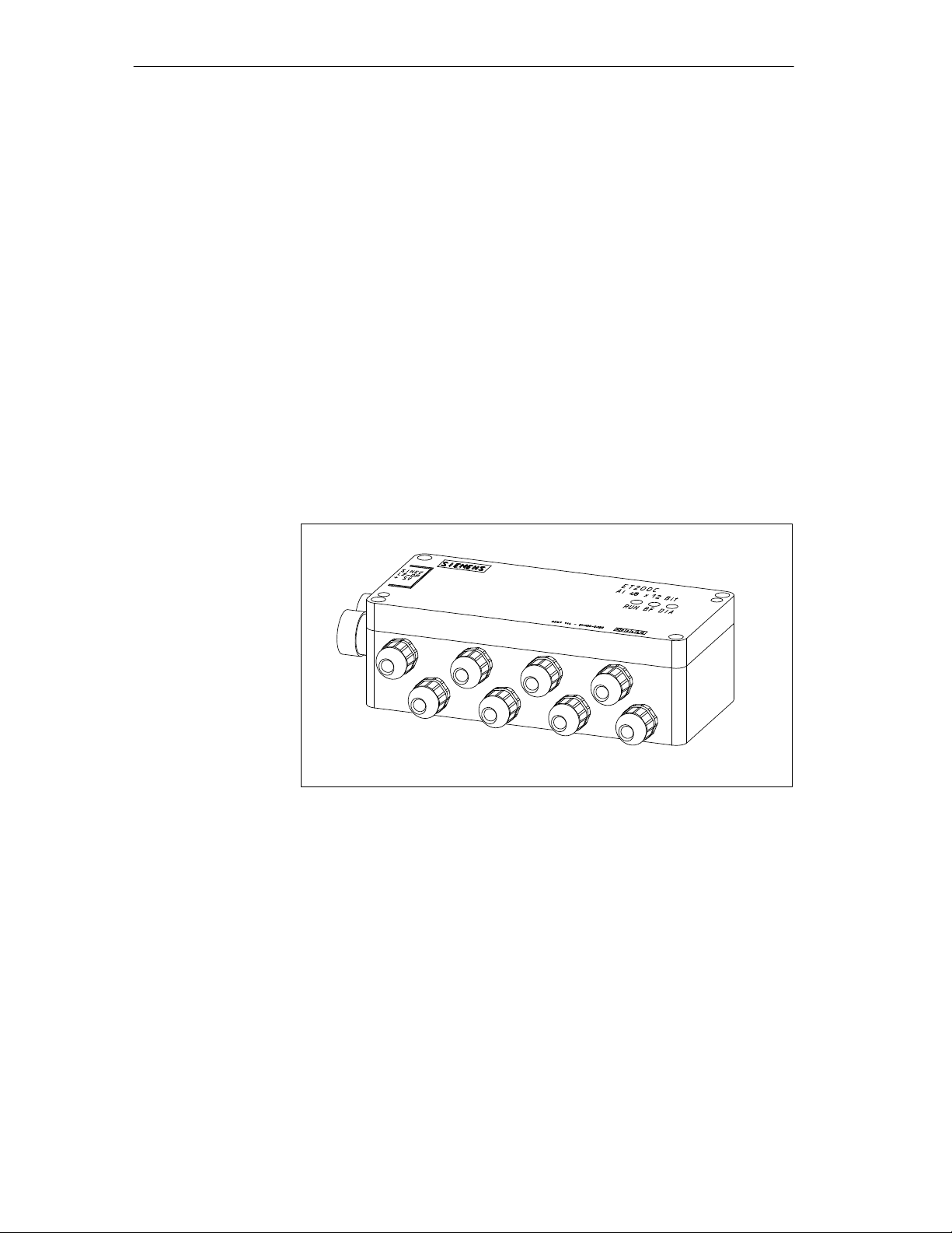
ET 200C Components
Analog Input Module ET 200C; AI 4/8 12 Bit (6ES7 144-0KH00-0XB0),
Continued
Connections
The analog input module ET200C; AI 4/8 12 bit has the following connections:
8 input channels for thermocouples and voltage sensors (2-wire)
or 4 input channels (4-wire)
2 bus connectors (12-pin socket)
The 12-pin sockets can be used for:
– connecting to the SINEC L2-DP field bus
– connecting to the power supply
– connecting to the combined field bus and power supply cable
The bus connectors are linked internally.
3-12
Figure 3-6 Analog Input Module ET 200C; AI 4/8 12 Bit
(6ES7 144-0KH00-0XB0)
ET 200C Distributed I/O Station
EWA 4NEB 812 6119-02b
Page 57

3.6 Analog Input Module ET 200C; AI 4 12 Bit (6ES7 144-0HF00-0XB0)
ET 200C Components
Characteristics
The analog input module ET 200C; AI 4 12 bit has the following
characteristics:
Degree of protection IP 66/IP 67 (see Installation Rules, Section 4.1)
Choice of the following baud rates: 9.6; 19.2; 93.75; 187.5; 500 and
1500 kbaud
Measuring principle: momentary value encryption (successive
approximation)
Measuring range selectable separately for each channel group
– " 1.25 V
– " 2.5 V
– " 5V
– " 10 V
– " 20 mA
– 0 ... 20 mA
– 4 ... 20 mA
Channel diagnostics of inputs for range overshoot and parameterization
error (can be switched off with COM ET 200, see Section 5.1.4).
Channel diagnostics can be evaluated only via the IM 308-C master
interface. Each diagnostics message causes the ”DIA” LED to light up.
ET 200C Distributed I/O Station
EWA 4NEB 812 6119-02b
LEDs for
– RUN
– BF (bus fault)
– DIA (module diagnostics)
No need to open the cover to secure the module (see drill-hole templates
at the back of the manual).
3-13
Page 58

ET 200C Components
Analog Input Module ET 200C; AI 4 12 Bit (6ES7 144-0HF00-0XB0),
Continued
Connections
The analog input module ET200C; AI 4 12 bit has the following connections:
4 input channels (2-wire)
2 bus connectors (12-pin socket)
The 12-pin sockets can be used for:
– connecting to the SINEC L2-DP field bus
– connecting to the power supply
– connecting to the combined field bus and power supply cable
The bus connectors are linked internally.
3-14
Figure 3-7 Analog Input Module ET 200C; AI 4 12 Bit (6ES7 144-0HF00-0XB0)
ET 200C Distributed I/O Station
EWA 4NEB 812 6119-02b
Page 59

3.7 Analog Output Module ET 200C; AO 4 12 Bit (6ES7 145-0HF00-0XB0)
ET 200C Components
Characteristics
The analog output module ET 200C; AO 4 12 bit has the following
characteristics:
Degree of protection IP 66/IP 67 (see Installation Rules, Section 4.1)
Choice of the following baud rates: 9.6; 19.2; 93.75; 187.5; 500 and
1500 kbaud
Output ranges selectable separately for each channel group
– " 10 V
– 0 ... 10 V
– " 20 mA
– 0 ... 20 mA
– 4 ... 20 mA
Channel diagnostics of outputs for wire break, range overshoot,
common-mode voltage overshoot, short-circuit and parameterization error
(can be switched off with COM ET 200, see Section 5.1.4).
Channel diagnostics can be evaluated only via the IM 308-C master
interface. Each diagnostics message causes the ”DIA” LED to light up.
LEDs for
– RUN
– BF (bus fault)
– DIA (module diagnostics)
No need to open the cover to secure the module (see drill-hole templates
at the back of the manual).
ET 200C Distributed I/O Station
EWA 4NEB 812 6119-02b
3-15
Page 60
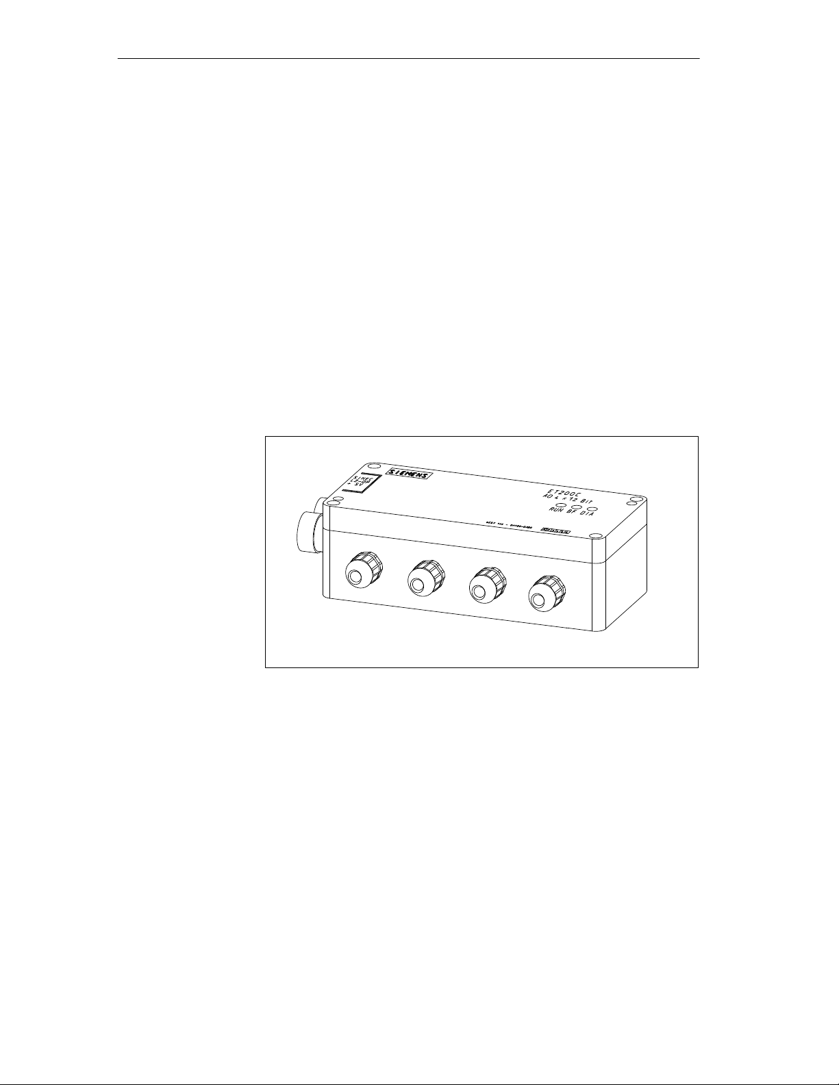
ET 200C Components
Analog Output Module ET 200C; AO 4 12 Bit (6ES7 145-0HF00-0XB0),
Continued
Connections
The analog output module ET200C; AO 4 12 bit has the following connections:
4 output channels
2 bus connectors (12-pin socket)
The 12-pin sockets can be used for:
– connecting to the SINEC L2-DP field bus
– connecting to the power supply
– connecting to the combined field bus and power supply cable
The bus connectors are linked internally.
3-16
Figure 3-8 Analog Output Module ET 200C; AO 4 12 Bit
(6ES7 145-0HF00-0XB0)
ET 200C Distributed I/O Station
EWA 4NEB 812 6119-02b
Page 61

3.8 T Connector (6ES5 762-2CT11)
ET 200C Components
Application
Characteristics
Connections
You need a T connector for the following configurations:
Configuration with power supply connector and with T connectors
(see Section 2.1.2)
Configuration with external current supply (see Section 2.1.4)
This means that the SINEC L2-DP field bus can also continue operating if a
slave station connected via a T connector is disconnected.
The T connector has the following characteristics:
Degree of protection IP 66/IP 67 (see Installation rules, Section 4.1)
Choice of following baud rates:
9.6; 19.2; 93.75; 187.5; 500; 1500; 3000; 6000 or 12000 kbaud
The baud rates 3000, 6000 and 12000 kbaud are only possible when the
module is operated with the IM 308-C (see Section 1.2).
A T connector has 3 bus connections:
T wo 12-pin sockets
One 12-pin male connector
The T connector is attached to the bus connection of an ET 200C module via
the 12-pin male connector. Both bus connections of the ET 200C module can
be used.
ET 200C Distributed I/O Station
EWA 4NEB 812 6119-02b
The bus connection can be used for several purposes (see digital modules).
Figure 3-9 T Connector
3-17
Page 62

ET 200C Components
3.9 Power Supply Connector (6ES5 762-2CS11)
Application
Characteristics
Connections
The power supply connector is used to combine the SINEC L2-DP field bus
and the external power supply.
The power supply connector has the following characteristics:
Degree of protection IP 66/IP 67 (see Installation rules, Section 4.1);
Choice of following baud rates:
9.6; 19.2; 93.75; 187.5; 500; 1500; 3000; 6000 or 12000 kbaud
Baud rates 3000, 6000 and 12000 kbaud are possible only for operation
with the IM 308-C and the digital modules (see Section 1.2).
Loadable with a maximum of 4 A input current. This limits the number of
digital input modules that can be connected (see Section 2.1.3).
Does not represent a bus node with station number
Attachment without opening the cover (drill-hole template at the back of
the manual).
The power supply connector has the following connections:
Connection for “Incoming” SINEC L2-DP field bus
(12-pin socket)
Connection for “Incoming” external power supply
(6-pin male connector)
Connection for “Outgoing” SINEC L2-DP field bus with power supply
(12-pin socket)
Grounding screw for connection of PE
Figure 3-10 Power Supply Connector
3-18
ET 200C Distributed I/O Station
EWA 4NEB 812 6119-02b
Page 63

3.10 Programmer Connector (6ES5 762-2CA12)
ET 200C Components
Application
Characteristics
Connections
A programmer connector is used to connect the programmer within the
IP 66/IP 67 environment to the SINEC L2-DP bus.
The programmer connector has the following characteristics:
Degree of protection IP 66/IP 67 (see Installation rules, Section 4.1)
Choice of following baud rates:
9.6; 19.2; 93.75; 187.5; 500; 1500; 3000; 6000 or 12000 kbaud
Baud rates 3000, 6000 and 12000 kbaud are possible only for operation
with the IM 308-C and the digital modules (see Section 1.2).
Can be placed anywhere on the bus (exception: the programmer
connector may not be attached to the ends of the bus cable, since there is
then no space for the terminating resistor).
Does not represent a bus node with station number
Attachment without opening the cover (drill-hole template at the back of
the manual).
A programmer connector has three bus connections:
Connection for “Incoming” SINEC L2-DP field bus (possibly with power
supply) (12-pin socket)
Connection for “Outgoing” SINEC L2-DP field bus (possibly with power
supply) (12-pin socket)
Connection for adapter cable (see Section 3.13) to the programmer
(12-pin socket)
Figure 3-11 Programmer Connector
ET 200C Distributed I/O Station
EWA 4NEB 812 6119-02b
3-19
Page 64

ET 200C Components
3.11 Cables
Types of Cables
Versions
The ET 200C can be used in various configurations for which you require the
correct cables. The following types of cable are available.
Table 3-1 ET 200C Cables
Number of
Cores
Application
2 SINEC L2-DP field bus, power supply is not incorporated
5 For SINEC L2-DP field bus and power supply in one cable
or
For feeding the power supply to the power connector
or
For external load voltage supply.
Various different cables are available from SIEMENS for the ET 200C.
All of the cables are available precut and terminated at both ends, one end or
not at all
with 12-pin male connector for SINEC L2-DP bus connection and/or
power supply
and/or
with 6-pin connection for load voltage supply.
You can, however, also prepare the cables yourself. The necessary information can be found in Section 4.3.
Note
All prefabricated cables have a core cross-sectional area of 0.75 mm
maximum current load of 4 A.
You will require cables with a minimum core cross-sectional area of
2.5 mm
2
for the load voltage supply of ET 200C; DO 8 DC 24V/2A and
ET 200C; DI 16/DO 16 DC 24V/2A. You must prepare these cables
yourself.
You must also prepare the cable for feeding separate power supplies
yourself.
2
for a
3-20
ET 200C Distributed I/O Station
EWA 4NEB 812 6119-02b
Page 65

ET 200C Components
Order numbers
Table 3-2 Order Numbers for Standard Cable Lengths (Core Cross-Sectional Area 0.75 mm2/Max. Current
Load 4 A)
The following table contains the order numbers for standard cable lengths:
Description Cable
(standard sheath)
(non-welding sheath)
Cable
5-core cable (not prefabricated) 6ES5 717-11 6ES5 718-11
5-core cable, prefabricated at one end
6ES5 717-21 6ES5 718-21
(6-pin circular socket)
5-core cable, prefabricated at both ends
6ES5 717-31 6ES5 718-31
(6-pin circular socket/6-pin circular connector)
5-core cable, prefabricated at one end
(12-pin circular connector)
1
5-core cable, prefabricated at both ends
(12-pin circular connector)
6ES5 717-61 6ES5 718-61
6ES5 717-71
° ° °
6ES5 718-71
° ° °
Length
0.5 m
1 m
2 m
5 m
10 m
A B 4
B B 0
B C 0
B F 0
C B 0
A B 4
B B 0
B C 0
B F 0
C B 0
1
Do not use for feeding the power supply separately (as bus cable is connected ³ may cause interference on the bus)
If you require cables of a different length, you can order these using Z numbers.
Specify the order number and the desired length, e.g. 6ES5 717-1AA01-Z
3.50 m.
Table 3-3 Order Numbers for Standard Cable Lengths (Core Cross-Sectional Area 0.75 mm2/Max. Current
Load 4 A)
Description Cable
(standard sheath)
(non-welding sheath)
Cable
5-core cable (not prefabricated) 6ES5 717-1AA01-Z 6ES5 718-1AA01-Z
5-core cable, prefabricated at one end
6ES5 717-2AA01-Z 6ES5 718-2AA01-Z
(6-pin circular socket)
5-core cable, prefabricated at both ends
6ES5 717-3AA01-Z 6ES5 718-3AA01-Z
(6-pin circular socket/6-pin circular connector)
5-core cable, prefabricated at one end
(12-pin circular connector)
1
5-core cable, prefabricated at both ends
6ES5 717-6AA01-Z 6ES5 718-6AA01-Z
6ES5 717-7AA01-Z 6ES5 718-7AA01-Z
(12-pin circular connector)
1
Do not use for feeding the power supply separately (as bus cable is connected ³ may cause interference on the bus)
ET 200C Distributed I/O Station
EWA 4NEB 812 6119-02b
3-21
Page 66

ET 200C Components
3.12 Terminating Resistor (6ES5 755-2CA11)
Application
Characteristics
A bus cable must always be terminated at both ends with a terminating resistor.
On the ET 200C, the terminating resistor is screwed onto a 12-pin socket.
The terminating resistor can be screwed onto the bus connection of:
Digital and analog modules, or
T connector
The terminating resistor has
Degree of protection IP 66/IP 67 (see Installation rules, Section 4.1)
Figure 3-12 Terminating Resistor
3-22
ET 200C Distributed I/O Station
EWA 4NEB 812 6119-02b
Page 67

3.13 Adapter Cable (6ES5 755-8CA11)
ET 200C Components
Application
Characteristics
Connections
The adapter cable is required for connecting the programmer (with programmer interface module CP5410-S5DOS/ST) or the ET 200 handheld to the
ET 200C.
The programmer or the ET 200 handheld are required for
Setting the station number (digital modules only with ET 200 handheld,
anlog modules optionally with ET200 handheld)
T est and startup
Diagnostics functions
The adapter cable has the following characteristics:
Degree of protection IP 66/IP 67 (see Installation rules, Section 4.1) only
at the end with the IP 66/IP 67 bus connector
Choice of following baud rates:
9.6; 19.2; 93.75; 187.5; 500; 1500; 3000; 6000 or 12000 kbaud
The baud rates 3000, 6000 and 12000 kbaud are only possible when
operating with the IM 308-C and digital modules (see Section 1.2).
The adapter cable has the following connections:
Bus connector in IP 20 (9-pin connector)
Bus connector in IP 66/IP 67 (12-pin connector)
In order to connect the programmer, you also require the programmer connecting cable.
Figure 3-13 Adapter Cable
ET 200C Distributed I/O Station
EWA 4NEB 812 6119-02b
3-23
Page 68

ET 200C Components
3-24
ET 200C Distributed I/O Station
EWA 4NEB 812 6119-02b
Page 69

Mechanical and Electrical Installation
4
In this Chapter
This chapter describes the mechanical and electrical installation of the
ET 200C.
ET 200C Distributed I/O Station
EWA 4NEB 812 6119-02b
4-1
Page 70

Mechanical and Electrical Installation
4.1 Installation of ET 200C
Rules
Degree of
protection
IP 66/IP 67
Installation
Degree of protection IP 66/IP 67 can be guaranteed for the ET 200C modules
only under the following conditions:
The surfaces on which the ET 200C modules are mounted must be flat
(no tensions)
All unused connections must always be sealed with the plastic caps
supplied (inputs/outputs only) or metal caps.
IP 66/IP 67 is not guaranteed if the transparent caps for transport are used.
Bear the following in mind with regard to degree of protection IP 66/IP 67:
Before startup, check the security of all metal and plastic seals on the
ET 200C distributed I/O station.
The ET 200C modules can be installed in any position and inclined at any
angle.
Note the minimum distances between ET 200C modules and cable ducts:
Table 4-1 Distances between ET 200C Modules and Cable Ducts
Between ET 200C module and cable duct ... Distance
.... no T connector is installed 10 cm
... a T connector is installed 5 cm
Captive M4 securing screws are used. You will require a 3.0 mm wrench for
socket-head screws to DIN 911 for installation and removal.
Use the drill-hole templates at the back of this manual to install the ET 200C
modules. Secure each module to a flat surface or carrier using two M4
screws.
4-2
ET 200C Distributed I/O Station
EWA 4NEB 812 6119-02b
Page 71

Mechanical and Electrical Installation
4.2 Electrical Wiring of the ET 200C Distributed I/O Station
Introduction
Both grounded and ungrounded configurations are possible.
The following two sections include a circuit example for
Grounded configuration and
Ungrounded configuration.
The text contains code numbers, which are references to the respective diagram.
Note
We recommend the grounded configuration for analog modules. This
configuration provides additional protection against electromagnetic
interference.
ET 200C Distributed I/O Station
EWA 4NEB 812 6119-02b
4-3
Page 72

Mechanical and Electrical Installation
4.2.1 Grounded Configuration
Definition
Rules
In a grounded configuration, the ground and PE potentials are connected.
For the grounded configuration, the following must be taken into account:
You must provide a main switch (1) according to VDE 0100 for the
ET 200C modules, the sensors and the actuators.
You need a fuse (2) for the mains connection of the load power supply
unit.
Use a Siemens load power supply unit of the 6EV1 series (see Catalog
ET 1) for power supply and load voltage supply.
If you use any other load power supply (24 V DC), note that the voltage
must be in the range of 20 V DC to 30 V DC (including ripple). The load
power supply must generate a functional extra-low voltage with
protective separation in accordance with VDE 0106, Part 101. If you use
a switched-mode power supply, you will need a back-up capacitor (with a
rating of 200 F per 1 A load current) (3).
You should provide in secondary circuit a connection (4) to the protective
conductor on the load power supply (terminal M).
You need a main power fuse to protect the supply voltage (5).
For both grounded and ungrounded configurations, use a low-resistance
conductor to connect the protective ground (PE) terminal of the ET 200C
modules (digital and analog modules, power supply connector,
programmer connector) to the protective ground conductor or the chassis
ground (machine ground) (6).
4-4
The right-hand side of the power supply connector features a screw for
connecting the protective ground conductor. PE is looped in via the power
supply connector.
In addition, the protective ground conductor must be connected to the PE
pin in the 12-pin round connector or 6-pin round connector. PE pin and
housing are linked internally.
All machine parts must be grounded.
Use a minimum cross-section of 10 mm
ground connections!
2
for equipotential bonding and
ET 200C Distributed I/O Station
EWA 4NEB 812 6119-02b
Page 73

Mechanical and Electrical Installation
Configuration
The grounded configuration for the ET 200C is shown below.
(1)
L1
L2
L3
N
PE
(2)
(4)
ML+
Connection
for Grounded
Configuration
(3)
(5)
L+
L+
M
M
PE
PE
(6)
L+
M
PE
PS
Conn.
ET 200C
Sensor/
Actuator
L+
M
ET 200C
PE
I/O
PE
I/O
ML+
Figure 4-1 Grounded Configuration for ET 200C with 24 V DC Current/Load
Voltage Supply
Sensor/
Actuator
PE
ET 200C Distributed I/O Station
EWA 4NEB 812 6119-02b
4-5
Page 74

Mechanical and Electrical Installation
4.2.2 Ungrounded Configuration
Definition
Rules
In an ungrounded configuration, there is no connection between the load
power supply (M terminal) and the protective ground conductor (PE). The
protective ground conductor loses its protective function.
The internal design of the digital and analog modules is such that the supply
voltage is connected to the protective ground conductor through a capacitor,
in order to dissipate high-frequency interference.
For the ungrounded configuration, the following must be taken into account:
You must provide a main switch (1) according to VDE 0100 for the
ET 200C modules, the sensors and the actuators.
You need a fuse (2) for the mains connection of the load power supply
unit.
Use a Siemens load power supply unit of the 6EV1 series (see Catalog
ET 1) for power supply and load voltage supply.
If you use any other load power supply (24 V DC), note that the voltage
must be in the range of 20 V DC to 30 V DC (including ripple). The load
power supply must generate a functional extra-low voltage with
protective separation in accordance with VDE 0106, Part 101. If you use
a switched-mode power supply, you will need a back-up capacitor (with a
rating of 200 F per 1 A load current) (3).
You need a main power fuse to protect the supply voltage (5).
For both grounded and ungrounded configurations, use a low-resistance
conductor to connect the protective ground (PE) terminal of the ET 200C
modules (digital modules, power supply connector, programmer
connector) to the protective ground conductor or the chassis ground
(mache ground) (6).
The right-hand side of the power supply connector features a screw for
connecting the protective ground conductor. PE is looped in via the power
supply connector.
In addition, the protective ground conductor must be connected to the PE
pin in the 12-pin round connector or 6-pin round connector. PE pin and
housing are linked internally.
You must provide insulation monitoring to ground with voltage clamping
(7).
Warning
!
The ungrounded configuration can be neutralized by grounded machine parts
and grounded electrical devices.
Example: A grounded sensor or actuator links the PE protective ground to
the M potential of the control system.
4-6
ET 200C Distributed I/O Station
EWA 4NEB 812 6119-02b
Page 75

Mechanical and Electrical Installation
Configuration
The ungrounded configuration for the ET 200C is shown below.
(1)
L1
L2
L3
N
PE
(2)
(7)
>U
(3)
ML+
(5)
L+
L+
M
M
PE
PE
(6)
L+
M
PE
PS
Conn.
ET 200C
L+
M
PE
Sensor/
Actuator
ET 200C
I/O
I/O
Sensor/
ML+
Figure 4-2 Ungrounded Configuration for ET 200C
Actuator
ET 200C Distributed I/O Station
EWA 4NEB 812 6119-02b
4-7
Page 76

Mechanical and Electrical Installation
4.3 Wiring of the ET 200C
Introduction
Circular
Connectors/
Sockets
Prefabricated cables are available from Siemens for the bus connection and
the power/load voltage supply (see section 3.10). If you use prefabricated
cables, you do not have to read the following section.
Note
All prefabricated cables have a core cross-sectional area of 0.75 mm
2
for a
maximum current load of 4 A.
You will require cables with a minimum core cross-sectional area of
2.5 mm
2
for the load voltage supply of ET 200C; DO 8 DC 24V/2A and
ET 200C; DI 16/DO 16 DC 24V/2A. You must prepare these cables
yourself.
You must also prepare the cable for feeding separate power supplies
yourself.
Read the following instructions if you wish to prepare the cables yourself.
You will require 6-pin and 12-pin circular connectors/sockets for connecting
the bus, power supply and the load voltage supply.
The following table contains the order numbers for 6-pin and 12-pin circular
connectors:
4-8
Table 4-2 Order Numbers for Circular Connectors
Round connector/socket
6-pin connector with a socket insert
(not prefabricated)
6-pin connector with pin insert
(not prefabricated)
12-pin connector with pin insert
(not prefabricated)
Order number
6ES5 760-2CA11
6ES5 760-2CA21
6ES5 760-2CB11
You will require 5-pin circular connectors with pin inserts and M12 external
thread to connect the inputs/outputs of the following modules:
ET 200C; DI 8 DC 24V
ET 200C; DO 8 DC 24V/0.5A
ET 200C; DO 8 DC 24V/2A
ET 200C; DI 16/DO 16 DC 24V/2A (6ES7 143-0BL00-0XB0)
ET 200C Distributed I/O Station
EWA 4NEB 812 6119-02b
Page 77

Mechanical and Electrical Installation
The corresponding 5-pin circular connectors with pin inserts are available
from companies such as Kostal or Lumberg.
Rules:Circular
Connectors/
Sockets
Conduit-Thread
Glands
The following applies for all connections to circular connectors:
Remove the cable insulation so that the screw is tightly held by the
clamping ring in the circular connector.
Always use the same core color for the same signal.
For the green/red SINEC L2 cable, for example, always connect the green
wire to terminal A and the red wire to terminal B.
The inputs/outputs of the
ET 200C; DI 16/DO 16 DC 24V/2A (6ES7 143-0BL10-0XB0)
ET 200C; AI 4/8 12 bit (6ES7 144-0KH00-0XB0)
ET 200C; AI 4 12 bit (6ES7 144-0HF00-0XB0)
ET 200C; AO 4 12 bit (6ES7 145-0HF00-0XB0)
are connected by means of cable glands which carry the cable through the
housing and into the module. Connect the cables as indicated by the labels on
the terminals (see Section 4.3.4).
The inputs/outputs have conduit threads in order to secure the signal lines
and to ensure that the appropriate degree of protection is provided in accordance with IP 66/IP 67.
Rules:
Conduit-Thread
Glands
The cables for ET 200C modules with conduit thread glands must comply
with the following specifications:
Digital modules: ∅ 8 mm cable (PG 9 conduit thread)
Analog modules: ∅ 4.5 ... 6 mm cable
(e.g. 4 0.25 mm
2
or 2 0.34 mm2)
ET 200C Distributed I/O Station
EWA 4NEB 812 6119-02b
4-9
Page 78

Mechanical and Electrical Installation
4.3.1 Wiring of the Bus Connection
Note
The bus connection is a 12-pin socket of the ET 200C module.
Introduction
The following ET 200C modules have a bus connection:
Digital modules (2 bus connections)
Analog modules (2 bus connections)
T connector (2 bus connections – a 3rd bus connection is screwed directly
onto the ET 200C module)
Power supply connector (2 bus connections, 1 SINEC L2-DP,
1 power supply and SINEC L2-DP together)
Programmer connector (3 bus connections)
8DI
8DO
8DO/2A
16DI/16DO
PS
SV
Conn.
PG
4-10
4AI
4/8AI
4AO
Figure 4-3 Bus Connections of the ET 200C Modules
All ET 200C modules have a socket as bus connection, i.e. a plug connector
must be used for all cables as connector.
ET 200C Distributed I/O Station
EWA 4NEB 812 6119-02b
Page 79

Mechanical and Electrical Installation
Connection
Options
!
Connecting only
SINEC L2-DP
The SINEC L2-DP and power supply can be connected in one of three ways:
SINEC L2-DP only connected to the bus connection
Power supply only connected to the bus connection
SINEC L2-DP and power supply connected to a bus connection.
Warning
If you connect an external power supply to a bus connection,
It is only permissible to connect the 2-core (!) SINEC L2 bus cable to the
second bus connection.
It is only permissible to connect the 2-core (!) SINEC L2 bus cable
where a T connector is used.
If you only wish to connect the SINEC L2-DP bus, you will require
12-pin circular connectors
SINEC L2 2-core cable
Connect the circular connectors in accordance with the following table:
Table 4-3 Pin Assignment of the Bus Connection where only the SINEC L2-DP is
Connected
Pin Assignment Pin Assignment
1 reserved 7 reserved
2 A (green) 8 reserved
3 reserved 9 reserved
4 B (red) 10 reserved
5 reserved 11 reserved
6 reserved 12 reserved
ET 200C Distributed I/O Station
EWA 4NEB 812 6119-02b
4-11
Page 80

Mechanical and Electrical Installation
Wiring of the Bus Connection, Continued
Connecting only
power supply
Connecting
SINEC L2-DP and
Power Supply
If you only wish to connect the power supply, you require
12-pin circular connectors
3-core cable with a diameter of 6 to 10 mm.
Connect the circular connectors in accordance with the following table:
Table 4-4 Pin Assignment of the Bus Connection where only the Power Supply is
Connected
Pin Assignment Pin Assignment
1 reserved 7 P 24 V
2 reserved 8 M 24 V
3 reserved 9 PE
4 reserved 10 reserved
5 reserved 11 reserved
6 reserved 12 reserved
If you combine the SINEC L2-DP bus and the power supply in a single cable,
you will require
12-pin circular plugs
Sealing of Unused
Connections
4-12
5-core cable with a diameter of 6 to 10 mm.
Table 4-5 Pin Assignment of the Bus Connection if SINEC L2-DP and Power
Supply are Connected
Pin Assignment Pin Assignment
1 reserved 7 P 24 V
2 A (green) 8 M 24 V
3 reserved 9 PE
4 B (red) 10 reserved
5 reserved 11 reserved
6 reserved 12 reserved
Connections which are not required must be sealed using the enclosed metal
caps.
ET 200C Distributed I/O Station
EWA 4NEB 812 6119-02b
Page 81
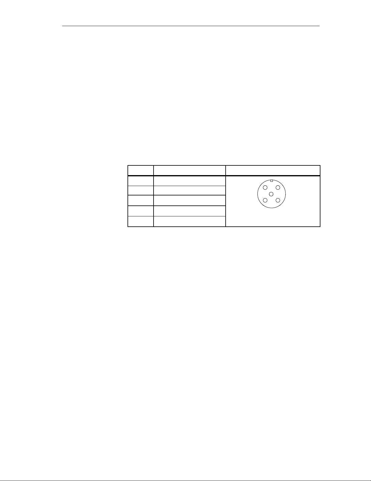
12
5
34
View: Mating Side
Mechanical and Electrical Installation
4.3.2 Wiring of ET 200C; DI 8 DC 24V (6ES7 141-0BF00-0XB0)
Connecting Inputs
T o wire the inputs you will require
5-pin circular plugs
Flexible 4-core Cu cables with a minimum core cross-section of
0.75 mm
Connect the inputs in accordance with the pin assignment in the following
table.
Table 4-6 Pin Assignment of the Inputs of ET 200C; DI 8 DC 24V
Pin
1 24 V DC
2 Free
3 Ground
4 Signal
5 PE
1
The module supplies this 24 V DC at pin 1 as the voltage supply for the connected
sensors.
2
.
(6ES7 141-0BF00-0XB0)
Input View
1
4
Sealing of Unused
Inputs
Inputs which are not required must be sealed using the enclosed twist caps.
ET 200C Distributed I/O Station
EWA 4NEB 812 6119-02b
4-13
Page 82

Mechanical and Electrical Installation
Wiring of ET 200C; DI 8 DC 24V (6ES7 141-0BF00-0XB0), Continued
Return Sensor
Supply to Inputs
The following must be noted if you feed the sensor supply of an input directly to an input (”Read back output” function):
If no load is connected,
– the diagnostics for the sensor supply must be disconnected in the
COM ET 200 (see Section 5.1.4) or
– a resistor (2.4 kW) must be connected to ground at the input for
wire-break recognition.
Wire-Break Recognition with 2.4-kW Resistor
Output Input
2,4 kW
Figure 4-4 Sensor Supply Returned to Input without Load
If a load is connected, only a wire break on the connection to the load will
be recognized. The connection between the sensor supply and the input
cannot be monitored for wire breaks.
4-14
Wire-Break Recognition with Load
Output Input
Wire-Break Recognition not
Load
Figure 4-5 Sensor Supply Returned to Input with Load
Possible
ET 200C Distributed I/O Station
EWA 4NEB 812 6119-02b
Page 83

12
5
34
View: Mating Side
Mechanical and Electrical Installation
4.3.3 Wiring of ET 200C; DO 8 DC 24V/0.5A (6ES7 142-0BF00-0XB0)
and ET 200C; DO 8 DC 24V/2A (6ES7 142-0BF10-0XB0)
Connecting
Outputs
Sealing of Unused
Outputs
T o wire the outputs you will require
5-pin circular plugs
Flexible 3-core Cu cables with a minimum core cross-section of
0.75 mm
Connect the outputs in accordance with the pin assignments in the table
below .
Table 4-7 Pin Assignments of the Outputs of ET 200C; DO 8 DC 24V/0.5A
Pin
1 Free
2 Free
3 Ground
4 Signal
5 PE
Outputs which are not required must be sealed using the enclosed twist caps.
2
.
(6ES7 142-0BF00-0XB0) and ET 200C; DO 8 DC 24V/2A
(6ES7 142-0BF10-0XB0)
Output View
4
ET 200C Distributed I/O Station
EWA 4NEB 812 6119-02b
4-15
Page 84

Mechanical and Electrical Installation
Wiring of ET 200C; DO 8 DC 24V/0.5A (6ES7 142-0BF00-0XB0) and
ET 200C; DO 8 DC 24V/2A (6ES7 142-0BF10-0XB0), Continued
Return Outputs to
Inputs
If you run an output or sensor supply input directly to an input (“Read back
output” function), you must take the following into account:
If no load is connected,
– the diagnostics for the output or sensor supply must be disconnected in
the COM ET 200 (see section 5.1.4) or
– a resistor (2.4 kW) must be connected to ground at the input for
wire-break recognition.
Wire-Break Recognition with 2.4 kW Resistor
Output Input
2.4 kW
Figure 4-6 Output Returned to Input without Load
If a load is connected, a wire break is only recognized on the connection
to the load. The output ³ input connection can not be monitored for
wire-break.
4-16
Wire-Break Recognition with Load
Output Input
No Wire-Break Recognition
Load
Figure 4-7 Output Returned to Input with Load
Possible
ET 200C Distributed I/O Station
EWA 4NEB 812 6119-02b
Page 85

12
5
34
View: Mating Side
12
5
34
Mechanical and Electrical Installation
4.3.4 Wiring of ET 200C; DI 16/DO 16 DC 24V/2A
(6ES7 143-0BL00-0XB0)
Connecting
Inputs/Outputs
T o wire the inputs/outputs you will require
5-pin circular plugs
Flexible 3-core Cu cables with a minimum core cross-section of
0.75 mm
Connect the inputs in accordance with the pin assignments in the following
table.
Table 4-8 Pin Assignments of the Inputs of ET 200C; DI 16/DO 16 DC 24V/2A
Pin Input View
1 24 V DC
2 Free
3 Ground
4 Signal
5 PE
1 The module supplies this 24 V DC at pin 1 as the voltage supply for the connected
sensors.
Connect the outputs in accordance with the pin assignments in the following
table.
2
.
(6ES7 143-0BL00-0XB0)
1
4
Sealing of Unused
Inputs/Outputs
ET 200C Distributed I/O Station
EWA 4NEB 812 6119-02b
Table 4-9 Pin Assignments of the Outputs of ET 200C; DI 16/DO 16 DC 24V/2A
(6ES7 143-0BL00-0XB0)
Pin Input View
1 Free
2 Free
3 Ground
4 Signal
5 PE
View: Mating Side
Seal all unused inputs/outputs with the screw caps supplied.
4-17
Page 86

Mechanical and Electrical Installation
Wiring of ET 200C; DI 16/DO 16 DC 24V/2A (6ES7 143-0BL00-0XB0),
Continued
Return Outputs to
Inputs
If you run an output or sensor supply input directly to an input (“Read back
output” function), you must take the following into account:
If no load is connected,
– the diagnostics for the output or sensor supply must be disconnected in
the COM ET 200 (see section 5.1.4) or
– a resistor (2.4 kW) must be connected to ground at the input for
wire-break recognition.
Wire-Break Recognition with 2.4 kW Resistor
Output Input
2.4 kW
Figure 4-8 Output Returned to Input without Load
If a load is connected, a wire break is only recognized on the connection
to the load. The output ³ input connection can not be monitored for
wire-break.
4-18
Wire-Break Recognition with Load
Output Input
No Wire-Break Recognition
Load
Figure 4-9 Output Returned to Input with Load
Possible
ET 200C Distributed I/O Station
EWA 4NEB 812 6119-02b
Page 87

Mechanical and Electrical Installation
4.3.5 Wiring of ET 200C; DI 16/DO 16 DC 24V/2A
(6ES7 143-0BL10-0XB0)
Connecting Inputs
and Outputs
Terminal
Assignments
Connect the signal lines to the screw terminals in the module.
Proceed as follows:
1. Open the module using a screwdriver.
2. Unscrew the conduit thread slightly, remove the seal and pull the signal
lines through the threaded joint.
3. Strip the signal lines and crimp the ends with wire end ferrules.
4. Connect the lines to the labelled, numbered terminals.
5. Pull the lines taught and tighten the conduit thread.
6. Fill in the labelling strips on the front of the module.
7. Close the module using a screwdriver.
Connect the signal lines in accordance with the terminal assignments in the
following table.
Table 4-10 Connection Assignments of ET 200C; DI 16/DO 16 DC 24V/2A
(6ES7 143-0BL10-0XB0)
Terminal Assignment
I0.0 ... I0.7 I0: Input .0 ... .7
Sealing of Unused
Inputs/Outputs
I1.0 ... I1.7 I1: Input .0 ... .7
Q0.0 ... Q0.7 Q0: Output .0 ... .7
Q1.0 ... Q1.7 Q1: Output .0 ... .7
24V 24 V DC (sensor supply)
0V Ground (sensor supply)
PE PE
M1 Ground (UL1)
M2 Ground (UL2)
Inputs/outputs which are not required must be sealed using the screw-type
seals.
ET 200C Distributed I/O Station
EWA 4NEB 812 6119-02b
4-19
Page 88

Mechanical and Electrical Installation
Wiring of ET 200C; DI 16/DO 16 DC 24V/2A (6ES7 143-0BL10-0XB0),
Continued
Arrangement of
the screw
terminals
Figure 4-10 shows the arrangement of the screw terminals of ET 200C;
DI 16/DO 16 DC 24V/2A (6ES7 143-0BL10-0XB0)
24V
I0.0
0V
PE
24V
I0.2
0V
PE
24V
I0.4
0V
PE
24V
I0.8
0V
PE
24V
I1.0
0V
PE
24V
I1.2
0V
PE
24V
I1.4
0V
PE
24V
I1.8
0V
PE
24V
I0.1
0V
PE
24V
I0.3
0V
PE
24V
I0.5
0V
PE
24V
I0.7
0V
PE
24V
I1.1
0V
PE
24V
I1.3
0V
PE
24V
I1.5
0V
PE
24V
I1.7
0V
PE
Q0.1
M1
PE
Q0.3
M1
PE
Q0.5
M1
PE
Q0.7
M1
PE
Q1.1
M2
PE
Q1.3
M2
PE
Q1.5
M2
PE
Q1.7
M2
PE
Q0.0
M1
PE
Q0.2
M1
PE
Q0.4
M1
PE
Q0.6
M1
PE
Q1.0
M2
PE
Q1.2
M2
PE
Q1.4
M2
PE
Q1.6
M2
PE
1
1
)
1
)
1
)
)
1
)
1)1)1
1
)
)
1) Screw terminals
Figure 4-10 Arrangement of Screw Terminals of ET 200C;
DI 16/DO 16 DC 24V/2A (6ES7 143-0BL10-0XB0)
pre-wired
4-20
ET 200C Distributed I/O Station
EWA 4NEB 812 6119-02b
Page 89

Mechanical and Electrical Installation
4.3.6 Wiring of ET 200C; AI 4/8 12 Bit (6ES7 144-0KH00-0KB0)
Connecting Inputs
Connect the signal cables to the screw terminals on the lower printed-circuit
board in the module.
Proceed as follows:
1. Open the module using a screwdriver.
2. Unscrew the cap of the conduit thread gland for the grounding cable and
remove the seal with the sleeve.
3. Push first the gland cap and then the seal onto the cable.
4. Cut back an appropriate length of the outer cable sheath.
5. Bend the braided shield at the end of the outer sheath up through 90°.
Push the sleeve with a twisting action over the foil until it is under the
braided shield in the outer sheath.
6. Trim off the braided shield flush with the outer edge of the sleeve.
7. Pull the ends of the signal cables though the glands with the foil and cut
off the foil.
8. Strip the ends of the signal lines and crimp the conductors with wire
ferrules.
9. Connect the lines to the corresponding terminals.
10.Pull the lines taut and tighten the gland.
11.Repeat steps 2 through 10 with other signal lines or close the module
using a screwdriver. When closing the module, make sure that the cover is
correctly seated as damage may occur if the cover is not aligned with the
casing.
ET 200C Distributed I/O Station
EWA 4NEB 812 6119-02b
Cap of Gland
Figure 4-11 Components of the Cable Gland for the Grounding Cable
Seal
Sleeve
Analog Module
with Gland for
Grounding Cable
Braided
Shield
Note
When you connect the signal lines, check that the DIL switches on the
printed circuit board (see Figure 4-12) remain easily accessible.
4-21
Page 90

Mechanical and Electrical Installation
Wiring of ET 200C; AI 4/8 12 Bit (6ES7 144-0KH00-0KB0), Continued
T erminal
Connect the signal lines to the terminals in accordance with the table below.
Assignment
Table 4-11 Connection Assignment of the Inputs of ET 200C; AI 4/8 12 Bit (6ES7 144-0KH00-0KB0)
Terminal Assignment for connection of ...
channel resistance sensor channel thermocouple voltage sensor
1 not used Compensator (+) not used
2 not used Compensator (–) not used
3
CH0
Measuring line (+)
4 Measuring line (–) Measuring line (–) Measuring line (–)
5 Constant current line I
6 Constant current line
–
I
C
7
CH1
Measuring line (+)
8 Measuring line (–) Measuring line (–) Measuring line (–)
9 Constant current line I
10 Constant current line
–
I
C
11
CH2
Measuring line (+)
12 Measuring line (–) Measuring line (–) Measuring line (–)
13 Constant current line I
14 Constant current line
–
I
C
15
CH3
Measuring line (+)
16 Measuring line (–) Measuring line (–) Measuring line (–)
17 Constant current line I
18 Constant current line
–
I
C
19 Analog ground (M
20 Analog ground (M
ANA
ANA
C+
CH0
CH1
Measuring line (+) Measuring line (+)
Measuring line (+) Measuring line (+)
Measuring line (–) Measuring line (–)
C+
CH2
CH3
Measuring line (+) Measuring line (+)
Measuring line (+) Measuring line (+)
Measuring line (–) Measuring line (–)
C+
CH4
CH5
Measuring line (+) Measuring line (+)
Measuring line (+) Measuring line (+)
Measuring line (–) Measuring line (–)
C+
CH6
CH7
Measuring line (+) Measuring line (+)
Measuring line (+) Measuring line (+)
Measuring line (–) Measuring line (–)
) Analog ground (M
) Analog ground (M
ANA
ANA
)
)
Sealing of Unused
Inputs
4-22
Seal all unused inputs with the screw caps supplied (module is supplied with
all inputs sealed).
ET 200C Distributed I/O Station
EWA 4NEB 812 6119-02b
Page 91

Mechanical and Electrical Installation
Arrangement of
Screw T erminals
and DIL Switches
Figure 4-12 shows the arrangement of screw terminals and DIL switches in
the ET 200C; AI 4/8 12 Bit.
Screw terminal labels for
resistance thermometers
CH0
CH1
CH2
CH3
M
ANA
COMP
+
-
+
-
+
-
+
-
+
-
+
-
+
-
+
-
CH0
V
CH1
V
CH2
V
CH3
.
V
.
CH4
V
CH5
V
CH6
V
CH7
V
M
ANA
+
-
S3
+
+
+
+
+
-
+
S2
+
-
+
-
S4
Screw terminal labels
for thermocouples and
voltage sensors
S1
DIL switches
Figure 4-12 Arrangement of Screw Terminals and DIL Switches in ET 200C;
AI 4/8 12 Bit
Table 4-12 DIL-Switch Blocks in the ET 200C; AI 4/8 12 Bit
DIL switch block Function Described in
S1 Manually set the station
Section 4.4.1
number
S2 Select 2-wire or 4-wire con-
Section 4.4.2
nection for Pt100 resistance
thermometers
S3 Select external/internal and
Section 4.4.2
floating/non-floating com-
pensation for thermocouples
S4 Select floating or non-floa-
Section 4.4.2
ting measurement
ET 200C Distributed I/O Station
EWA 4NEB 812 6119-02b
4-23
Page 92
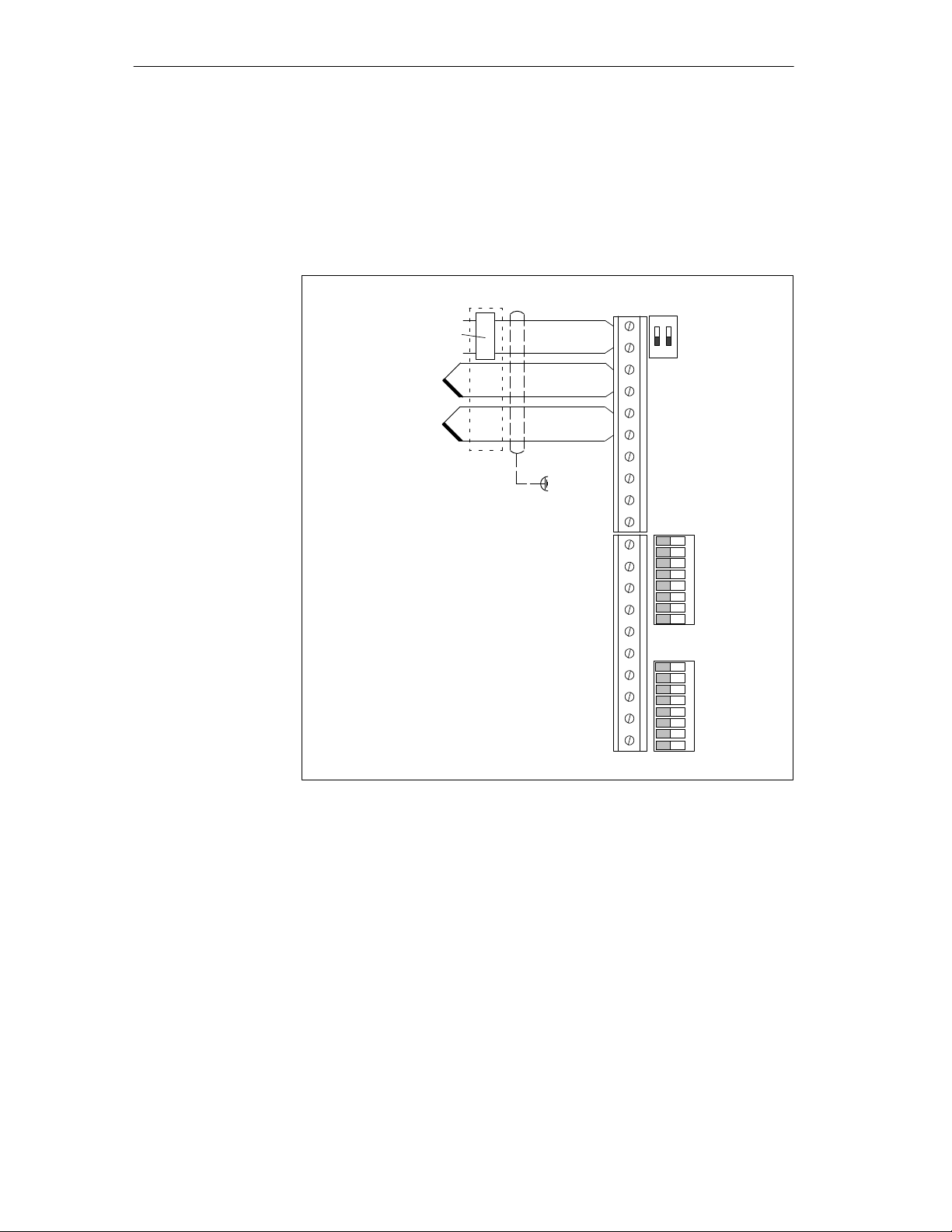
Mechanical and Electrical Installation
Wiring of ET 200C; AI 4/8 12 Bit (6ES7 144-0KH00-0KB0), Continued
Thermocouple:
Floating
Measurement and
Floating External
Compensation
The illustration on this page shows how thermocouples are connected for
floating measurement and external floating compensation:
1
OFF
S3
12345678
1
2345678
2
ON ON
S2 S4
ON ON
Compensator
Thermal
Coupling
+
COMP
CH0
CH1
CH2
CH3
CH4
CH5
CH6
CH7
-
+
-
+
-
+
-
+
-
+
-
+
-
+
-
+
-
.
.
.
.
.
Shield
4-24
M
ANA
Figure 4-13 Connection to ET 200C; AI 4/8 12 Bit of Thermocouples for Floating
Measurement and External Floating Compensation
ET 200C Distributed I/O Station
EWA 4NEB 812 6119-02b
Page 93

Mechanical and Electrical Installation
Thermocouple:
Non-Floating
Measurement and
Non-Floating
External
Compensation
The illustration on this page shows how thermocouples are connected for
non-floating measurement and external non-floating compensation:
1
OFF
S3
12345678
3456
2
S2 S4
ON ON
1
ON ON
2
Compensation
Thermal
Coupling
+
COMP
CH0
CH1
CH2
CH3
CH4
CH5
CH6
CH7
-
+
-
+
-
+
-
+
-
+
-
+
-
+
-
+
-
.
.
.
.
.
Shield
M
ANA
Figure 4-14 Connection to ET 200C; AI 4/8 12 Bit of Thermocouples for
Non-Floating Measurement and External Non-Floating Compensation
78
ET 200C Distributed I/O Station
EWA 4NEB 812 6119-02b
4-25
Page 94

Mechanical and Electrical Installation
Wiring of ET 200C; AI 4/8 12 Bit (6ES7 144-0KH00-0KB0), Continued
Thermocouple:
Non-Floating
Measurement and
Internal
Compensation
The illustration on this page shows how thermocouples are connected for
non-floating measurement and internal compensation:
1
.
.
.
.
.
Schirm
COMP
CH0
CH1
CH2
CH3
CH4
CH5
CH6
CH7
+
-
+
-
+
-
+
-
+
-
+
-
+
-
+
-
+
-
OFF
S3
12345678
3456
2
S2 S4
1
2
ON ON
ON ON
4-26
M
ANA
Figure 4-15 Connection to ET 200C; AI 4/8 12 Bit of Thermocouples for
Non-Floating Measurement and Internal Compensation
78
ET 200C Distributed I/O Station
EWA 4NEB 812 6119-02b
Page 95

Mechanical and Electrical Installation
Resistance
Thermometer,
2-Wire Circuit
The resistance of the resistance thermometer (Pt 100) is measured with the
aid of a 2-wire circuit. A maximum of four Pt 100 thermometers can be connected (1 resistance thermometer per channel group).
The resistance thermometer receives a constant current supply via terminals
CH0
/ CH2+ and CH0– / CH2–. Voltage drops on the measuring lines can
+
falsify the results of measurement. This type of measurement is of practical
value if the precision requirements are low.
The settings of the switches in DIL switch block S4 determine whether measurement is floating or non-floating (see Section 4.4.2).
Note
If a resistance thermometer (Pt100) is used for floating measurement, the
maximum permissible common-mode voltage is U
be overshot relative to M
at any differential input.
ANA
v "1V and must not
CM
The illustration below shows how resistance thermometers (Pt100) are connected to channel 0 and channel 2 in a 2-wire circuit for floating measurement:
Pt 100
Pt 100
.
Schirm
COMP
CH0
CH1
CH2
CH3
CH4
CH5
CH6
CH7
M
ANA
1
OFF
S3
5678
1
23456
78
2
DIL Switch Block S4:
DIL Switches 1 to 4 for
2-Wire Circuit ON
1234
ON ON
DIL Switch Block S4:
DIL Switches 1 and 3
S2 S4
for 4-Wire Circuit OFF
ON ON
+
-
+
-
+
-
+
-
+
-
+
-
+
-
+
-
+
-
ET 200C Distributed I/O Station
EWA 4NEB 812 6119-02b
Figure 4-16 Connection to ET 200C; AI 4/8 12 Bit of Resistance Thermometers
(Pt 100) in 2-Wire Circuit for Floating Measurement
4-27
Page 96

Mechanical and Electrical Installation
Wiring of ET 200C; AI 4/8 12 Bit (6ES7 144-0KH00-0KB0), Continued
Resistance
Thermometer,
4-Wire Circuit
The resistance of the resistance thermometer (Pt 100) is measured with the
aid of a 4-wire circuit.
The resistance thermometer receives a constant current Ic via terminals CH0
/ CH2+ and CH0– / CH2–. The voltage generated at the resistance thermometer is measured via CH1
/ CH3+ and CH1– / CH3–. In this configuration,
+
voltage fluctuations on the constant-current lines do not falsify the results of
measurement. The measuring inputs are high-ohmic, so the voltage drop on
the measuring lines is negligible.
Note
If a resistance thermometer (Pt100) is used for floating measurement, the
maximum permissible common-mode voltage is U
be overshot relative to M
at any differential input.
ANA
v "1V and must not
CM
The illustration below shows how resistance thermometers (Pt 100) are connected in a 4-wire circuit for floating measurement:
1
2
OFF
S3
1234
5678
S2 S4
1
23456
78
ON ON
ON ON
Pt 100
.
Pt 100
.
.
.
.
Shield
COMP
CH0
CH1
CH2
CH3
CH4
CH5
CH6
CH7
M
ANA
+
-
+
-
+
-
+
-
+
-
+
-
+
-
+
-
+
-
+
4-28
Figure 4-17 Connection to ET 200C; AI 4/8 12 Bit of Resistance Thermometers
(Pt 100) in 4-Wire Circuit for Floating Measurement
ET 200C Distributed I/O Station
EWA 4NEB 812 6119-02b
Page 97

Mechanical and Electrical Installation
Voltage Sensors
Free channels can be used to connect voltage sensors ("80 mV, "250 mV,
"500 mV, "1000 mV).
The settings of the switches in DIL switch block S4 determine whether measurement is floating or non-floating (see Section 4.4.2).
Note
If a voltage sensor is used for floating measurement, the maximum
permissible common-mode voltage is U
overshot relative to M
at any differential input.
ANA
v "1V and must not be
CM
The illustration below shows how voltage sensors are connected in a 2-wire
circuit for non-floating measurement:
1
OFF
S3
12345678
3456
2
S2 S4
ON ON
1
ON ON
2
+
COMP
-
+
U
–
+
U
–
.
Shield
CH0
CH1
CH2
CH3
CH4
CH5
CH6
CH7
+
-
+
-
+
-
+
-
+
-
+
-
+
-
+
-
ET 200C Distributed I/O Station
EWA 4NEB 812 6119-02b
M
ANA
Figure 4-18 Connection to ET 200C; AI 4/8 12 Bit of Voltage Sensors in 2-Wire
Circuit for Non-Floating Measurement
78
4-29
Page 98

Mechanical and Electrical Installation
4.3.7 Wiring of ET 200C; AI 4 12 Bit (6ES7 144-0HF00-0KB0)
Connecting Inputs
Connect the signal cables to the screw terminals on the lower printed-circuit
board in the module.
Proceed as follows:
1. Open the module using a screwdriver.
2. Unscrew the cap of the conduit thread gland for the grounding cable and
remove the seal with the sleeve.
3. Push first the gland cap and then the seal onto the cable.
4. Cut back an appropriate length of the outer cable sheath.
5. Bend the braided shield at the end of the outer sheath up through 90°.
Push the sleeve with a twisting action over the foil until it is under the
braided shield in the outer sheath.
6. Trim off the braided shield flush with the outer edge of the sleeve.
7. Pull the ends of the signal cables though the glands with the foil and cut
off the foil.
8. Strip the ends of the signal lines and crimp the conductors with wire
ferrules.
9. Connect the lines to the corresponding terminals.
10.Pull the lines taut and tighten the gland.
11.Repeat steps 2 through 10 with other signal lines or close the module
using a screwdriver. When closing the module, make sure that the cover is
correctly seated as damage may occur if the cover is not aligned with the
casing.
4-30
Cap of Gland
Figure 4-19 Components of the Cable Gland for the Grounding Cable
Seal
Braided
Shield
Sleeve
Analog Module
with Gland for the
Grounding Cable
Note
When you connect the signal lines, check that the DIL switches on the
printed circuit board (see Figure 4-20) remain easily accessible.
ET 200C Distributed I/O Station
EWA 4NEB 812 6119-02b
Page 99

Mechanical and Electrical Installation
T erminal
Assignment
Sealing of Unused
Inputs
Connect the signal lines to the terminals in accordance with the table below.
Table 4-13 Connection Assignment of the Inputs of ET 200C; AI 4 12 Bit
(6ES7 144-0HF00-0KB0)
Channel
CH0
CH1
CH2
CH3
Terminal Assignment
1 Measuring line (+)
2 Measuring line (–)
3 Measuring line (+)
4 Measuring line (–)
5 Measuring line (+)
6 Measuring line (–)
7 Measuring line (+)
8 Measuring line (–)
9 Analog ground (M
10 Analog ground (M
ANA
ANA
)
)
Seal all unused inputs with the screw caps supplied (module is supplied with
all inputs sealed).
ET 200C Distributed I/O Station
EWA 4NEB 812 6119-02b
4-31
Page 100

Mechanical and Electrical Installation
Wiring of ET 200C; AI 4 12 Bit (6ES7 144-0HF00-0KB0), Continued
Arrangement of
Screw T erminals
and DIL Switches
Figure 4-20 shows the arrangement of screw terminals and DIL switches in
the ET 200C; AI 4 12 bit
CH0
+
V
A
-
CH1
+
V
A
-
CH2
V
A
CH3
V
A
M
+
-
+
-
ANA
S1
DIL Switches
S5
4-32
Figure 4-20 Arrangement of Screw Terminals and DIL Switches in ET 200C;
AI 4 12 Bit
Table 4-14 DIL Switch Blocks in ET 200C; AI 4 12 Bit
DIL switch block Function Described in
S1 Manually set the station
Section 4.4.1
number
S5
Select voltage or current
Section 4.4.3
measurement
Select floating/non-floating
measurement
ET 200C Distributed I/O Station
EWA 4NEB 812 6119-02b
 Loading...