

Siemens SIMATIC ET 200AL User Manual

___________________
___________________
___________________
___________________
___________________
___________________
___________________
___________________
___________________
___________________
SIMATIC
ET 200AL
Communication module
CM 4xIO-Link 4xM12
(6ES7147-5JD00-0BA0)
Manual
10/2017
A5E32352322
-AE
Preface
Documentation guide
1
Product overview
2
Wiring
3
Parameters/address space
4
Diagnostics alarms
5
Technical specifications
6
Replacing modules
7
PROFIenergy
8
Dimension drawing
A
Siemens AG
Division Digital Fac
tory
Postfach 48 48
90026 NÜRNBERG
GERMANY
A5E32352322-AE
Ⓟ
11/2017 Subject to change
Copyright © Siemens AG 2014 - 2017.
All rights reserved
Legal information
Warning notice system
This manual contains notices you have to observe in order to ensure your personal safety, as well as to prevent
damage to property. The notices referring to your personal safety are highlighted in the manual by a safety alert
symbol, notices referring only to property damage have no safety alert symbol. These notices shown below are
graded according to the degree of danger.
DANGER
indicates that death or severe personal injury will result if proper precautions are not taken.
WARNING
indicates that death or severe personal injury may result if proper precautions are not taken.
CAUTION
indicates that minor personal injury can result if proper precautions are not taken.
NOTICE
indicates that property damage can result if proper precautions are not taken.
If more than one degree of danger is present, the warning notice representing the highest degree of danger will
be used. A notice warning of injury to persons with a safety alert symbol may also include a warning relating to
property damage.
Qualified Personnel
The product/system described in this documentation may be operated only by
personnel qualified
for the specific
task in accordance with the relevant documentation, in particular its warning notices and safety instructions.
Qualified personnel are those who, based on their training and experience, are capable of identifying risks and
avoiding potential hazards when working with these products/systems.
Proper use of Siemens products
Note the following:
WARNING
Siemens products may only be used for the applications described in the catalog and in the relevant technical
documentation. If products and components from other manufacturers are used, these must be recommended
or approved by Siemens. Proper transport, storage, installation, assembly, commissioning, operation and
maintenance are required to ensure that the products operate safely and without any problems. The permissible
ambient conditions must be complied with. The information in the relevant documentation must be observed.
Trademarks
All names identified by ® are registered trademarks of Siemens AG. The remaining trademarks in this publication
may be trademarks whose use by third parties for their own purposes could violate the rights of the owner.
Disclaimer of Liability
We have reviewed the contents of this publication to ensure consistency with the hardware and software
described. Since variance cannot be precluded entirely, we cannot guarantee full consistency. However, the
information in this publication is reviewed regularly and any necessary corrections are included in subsequent
editions.

Communication module CM 4xIO-Link 4xM12(6ES7147-5JD00-0BA0)
4 Manual, 10/2017, A5E32352322-AE
Preface
Purpose of the documentation
This manual supplements the ET 200AL distributed I/O system
(http://support.automation.siemens.com/WW/view/en/89254965) system manual. Functions
that are generally applicable to the ET 200AL distributed I/O system are described there.
The information provided in the present manual, the system manual and the function
manuals enables you to commission the ET 200AL distributed I/O system.
Conventions
Please also observe notes marked as follows:
Note
Indicates important product info
rmation to which particular attention should be paid.
Security information
Siemens provides products and solutions with industrial security functions that support the
secure operation of plants, systems, machines and networks.
In order to protect plants, systems, machines and networks against cyber threats, it is
necessary to implement – and continuously maintain – a holistic, state-of-the-art industrial
security concept. Siemens' products and solutions constitute one element of such a concept.
Customers are responsible for preventing unauthorized access to their plants, systems,
machines and networks. Such systems, machines and components should only be
connected to an enterprise network or the internet if and to the extent such a connection is
necessary and only when appropriate security measures (e.g. firewalls and/or network
segmentation) are in place.
For additional information on industrial security measures that may be implemented, please
visit (https://www.siemens.com/industrialsecurity).
Siemens' products and solutions undergo continuous development to make them more
secure. Siemens strongly recommends that product updates are applied as soon as they are
available and that the latest product versions are used. Use of product versions that are no
longer supported, and failure to apply the latest updates may increase customers' exposure
to cyber threats.
To stay informed about product updates, subscribe to the Siemens Industrial Security RSS
Feed under (https://www.siemens.com/industrialsecurity).

Communication module CM 4xIO-Link 4xM12(6ES7147-5JD00-0BA0)
Manual, 10/2017, A5E32352322-AE
5
Table of contents
Preface ...................................................................................................................................................... 4
1 Documentation guide ................................................................................................................................. 6
2 Product overview ..................................................................................................................................... 10
2.1 Properties ................................................................................................................................ 10
2.2 Operator controls and display elements ................................................................................. 13
2.3 Functions ................................................................................................................................ 14
2.4 Reset communication module to factory settings ................................................................... 14
3 Wiring ...................................................................................................................................................... 15
3.1 Terminal and block diagram ................................................................................................... 15
3.2 Pin assignment ....................................................................................................................... 16
4 Parameters/address space ...................................................................................................................... 19
4.1 Parameters ............................................................................................................................. 19
4.2 Explanation of the parameters ................................................................................................ 21
5 Diagnostics alarms .................................................................................................................................. 25
5.1 Status and error displays ........................................................................................................ 25
5.2 Diagnostics alarms .................................................................................................................. 27
6 Technical specifications ........................................................................................................................... 29
7 Replacing modules .................................................................................................................................. 32
8 PROFIenergy ........................................................................................................................................... 33
8.1 Pause function ........................................................................................................................ 33
8.2 DI operating mode .................................................................................................................. 34
8.3 DQ operating mode ................................................................................................................. 35
8.4 IO-Link operating mode .......................................................................................................... 36
A Dimension drawing .................................................................................................................................. 38
Communication module CM 4xIO-Link 4xM12(6ES7147-5JD00-0BA0)
6 Manual, 10/2017, A5E32352322-AE
1
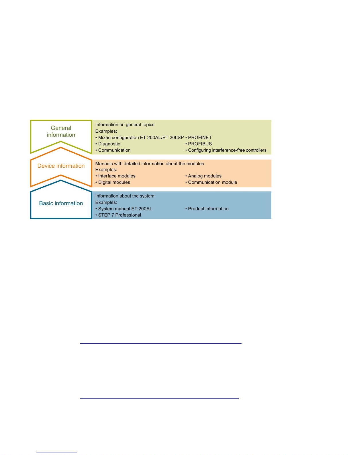
The documentation for the SIMATIC ET 200AL distributed I/O system is arranged into three
areas.
This arrangement enables you to access the specific content you require.
Basic information
The System Manual and Getting Started describe in detail the configuration, installation,
wiring and commissioning of the SIMATIC ET 200AL distributed I/O system. The STEP 7
online help supports you in the configuration and programming.
Device information
Product manuals contain a compact description of the module-specific information, such as
properties, terminal diagrams, characteristics and technical specifications.
General information
The function manuals contain detailed descriptions on general topics regarding the SIMATIC
ET 200AL distributed I/O system, e.g. diagnostics, communication, Motion Control, Web
server.
You can download the documentation free of charge from the Internet
(https://support.industry.siemens.com/cs/ww/en/view/109742667).
Manual Collection ET 200AL
The Manual Collection contains the complete documentation on the SIMATIC ET 200AL
distributed I/O system gathered together in one file.
You can find the Manual Collection on the Internet
(http://support.automation.siemens.com/WW/view/en/95242965).

Documentation guide
Communication module CM 4xIO-Link 4xM12(6ES7147-5JD00-0BA0)
Manual, 10/2017, A5E32352322-AE
7
"mySupport"
With "mySupport", your personal workspace, you make the best out of your Industry Online
Support.
In "mySupport", you can save filters, favorites and tags, request CAx data and compile your
personal library in the Documentation area. In addition, your data is already filled out in
support requests and you can get an overview of your current requests at any time.
You must register once to use the full functionality of "mySupport".
You can find "mySupport" on the Internet (https://support.industry.siemens.com/My/ww/en).
"mySupport" - Documentation
In the Documentation area in "mySupport" you can combine entire manuals or only parts of
these to your own manual.
You can export the manual as PDF file or in a format that can be edited later.
You can find "mySupport" - Documentation on the Internet
(http://support.industry.siemens.com/My/ww/en/documentation).
"mySupport" - CAx data
In the CAx data area in "mySupport", you can access the current product data for your CAx
or CAe system.
You configure your own download package with a few clicks.
In doing so you can select:
● Product images, 2D dimension drawings, 3D models, internal circuit diagrams, EPLAN
macro files
● Manuals, characteristics, operating manuals, certificates
● Product master data
You can find "mySupport" - CAx data on the Internet
(http://support.industry.siemens.com/my/ww/en/CAxOnline).
Application examples
The application examples support you with various tools and examples for solving your
automation tasks. Solutions are shown in interplay with multiple components in the system separated from the focus on individual products.
You will find the application examples on the Internet
(https://support.industry.siemens.com/sc/ww/en/sc/2054).

Documentation guide
Communication module CM 4xIO-Link 4xM12(6ES7147-5JD00-0BA0)
8 Manual, 10/2017, A5E32352322-AE
TIA Selection Tool
With the TIA Selection Tool, you can select, configure and order devices for Totally
Integrated Automation (TIA).
This tool is the successor of the SIMATIC Selection Tool and combines the known
configurators for automation technology into one tool.
With the TIA Selection Tool, you can generate a complete order list from your product
selection or product configuration.
You can find the TIA Selection Tool on the Internet
(http://w3.siemens.com/mcms/topics/en/simatic/tia-selection-tool).
SIMATIC Automation Tool
You can use the SIMATIC Automation Tool to perform commissioning and maintenance
activities simultaneously on different SIMATIC S7 stations as a bulk operation, independently
of the TIA Portal.
General function overview:
● Network browsing and creation of a table showing the accessible devices in the network
● Flashing of device LEDs or HMI display to locate a device
● Downloading of addresses (IP, subnet, gateway) to a device
● Downloading the PROFINET name (station name) to a device
● Placing a CPU in RUN or STOP mode
● Setting the time in a CPU to the current time of your PG/PC
● Downloading a new program to a CPU or an HMI device
● Downloading from CPU, downloading to CPU or deleting recipe data from a CPU
● Downloading from CPU or deleting data log data from a CPU
● Backup/restore of data from/to a backup file for CPUs and HMI devices
● Downloading service data from a CPU
● Reading the diagnostics buffer of a CPU
● Performing a CPU memory reset
● Resetting devices to factory settings
● Downloading a firmware update to a device
You can find the SIMATIC Automation Tool on the Internet
(https://support.industry.siemens.com/cs/ww/en/view/98161300).

Documentation guide
Communication module CM 4xIO-Link 4xM12(6ES7147-5JD00-0BA0)
Manual, 10/2017, A5E32352322-AE
9
PRONETA
With SIEMENS PRONETA (PROFINET network analysis), you analyze the system network
during commissioning. PRONETA features two core functions:
● The topology overview independently scans the PROFINET network and all connected
components.
● The IO check is a fast test of the wiring and the module configuration of a system.
You can find SIEMENS PRONETA on the Internet
(https://support.industry.siemens.com/cs/ww/en/view/67460624).
SINETPLAN
SINETPLAN, the Siemens Network Planner, supports you in planning automation systems
and networks based on PROFINET. The tool facilitates professional and predictive
dimensioning of your PROFINET installation as early as in the planning stage. In addition,
SINETPLAN supports you during network optimization and helps you to exploit network
resources optimally and to plan reserves. This helps to prevent problems in commissioning
or failures during productive operation even in advance of a planned operation. This
increases the availability of the production plant and helps improve operational safety.
The advantages at a glance
● Network optimization thanks to port-specific calculation of the network load
● Increased production availability thanks to online scan and verification of existing systems
● Transparency before commissioning through importing and simulation of existing STEP 7
projects
● Efficiency through securing existing investments in the long term and optimal exploitation
of resources
You can find SINETPLAN on the Internet (https://www.siemens.com/sinetplan).
Communication module CM 4xIO-Link 4xM12(6ES7147-5JD00-0BA0)
10 Manual, 10/2017, A5E32352322-AE
2
2.1
Properties
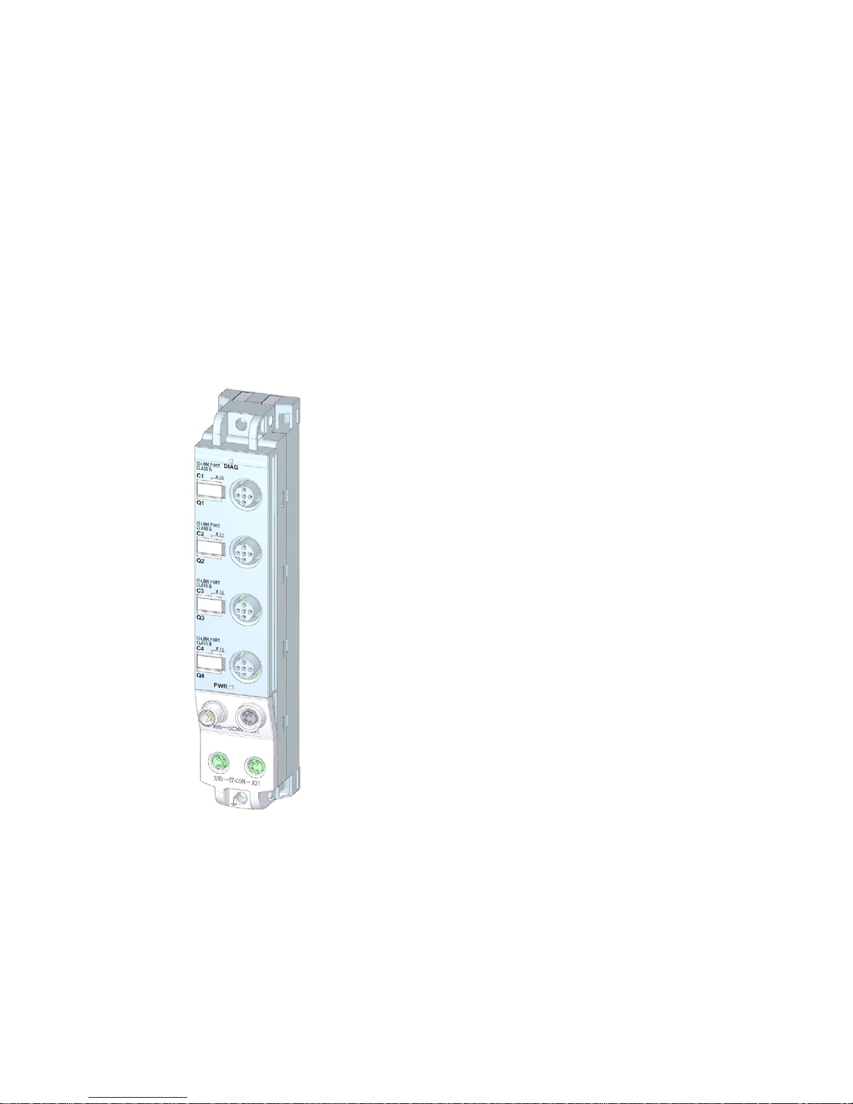
Article number
6ES7147-5JD00-0BA0
View of the module
Figure 2-1 View of the CM 4xIO-Link 4xM12 communication module

Product overview
2.1 Properties
Communication module CM 4xIO-Link 4xM12(6ES7147-5JD00-0BA0)
Manual, 10/2017, A5E32352322-AE
11
Properties
The module has the following technical properties:
● IO-Link Master according to IO-Link specification V1.1
● 4 ports, type class B
● 4 M12 connectors
● SIO mode (standard IO mode)
● Supported data transmission rates:
– COM1 (4.8 kBd)
– COM2 (38.4 kBd)
– COM3 (230.4 kBd)
● Configuration limits:
– Max. 32 bytes input and output data per port
– Max. 32 bytes input and output data per module
● Automatic backup of device parameters during replacement of the IO-Link device
(only for V1.1 devices)
● Suitable for connection of IO-Link devices with 3-wire and 5-wire connection
● Configurable diagnostics can be set for each channel
● Dimensions 30 x 159 mm
The module supports the following functions:
Table 2- 1 Version dependencies of the module functions
Function
Firmware version of the module
Firmware update
V1.0 or higher
Identification and maintenance data (I&M) V1.0 or higher
PROFIenergy
V1.0 or higher
IO-Link port configuration with S7-PCT (as of V3.2)
V1.0 or higher
IO-Link port configuration without S7-PCT
V1.1 or higher
Master backup with "IO_LINK_MASTER" function block
V1.1 or higher
Port Qualifier Information (PQI)
V1.1 or higher
Accessories
The following components are included in the module package:
● Identification labels
● Spacers

Product overview
2.1 Properties
Communication module CM 4xIO-Link 4xM12(6ES7147-5JD00-0BA0)
12 Manual, 10/2017, A5E32352322-AE
Other components
The following component can be ordered as spare part:
● Identification labels
The following components can be ordered as accessories:
● Connectors
● Cables
● Stripping Tool for ET-Connection
● M8 sealing cap
● M12 sealing cap
See also
You can find more information on accessories in the Accessories/spare parts section of the
ET 200AL distributed I/O system
(http://support.automation.siemens.com/WW/view/en/89254965) system manual.
 Loading...