

Siemens SIMATIC EM 300 User Manual

Important Information,
Contents
SIMATIC
EM 300 Motor Starters
Manual
Product Overview
Wiring
Commissioning
Hand-held Controller
Technical Specifications
SIGUARD Safety Integrated
Order Numbers
Dimension Drawings
1
2
3
4
5
6
A
B
GWA-4NEB 640070302-05
Edition 03/2010
Configuration Frame
Selection Help
Index
C
D

Safety guidelines
This manual contains notices which you should observe to ensure your own personal safety, as well as to protect the product and connected equipment. These notices are highlighted in the manual by a warning triangle
and are marked as follows according to the level of danger:
Danger
indicates that death, severe personal injury or substantial property damage will result if proper precautions
are not taken.
Warning
indicates that death, severe personal injury or substantial property damage can result if proper precautions are
not taken.
Caution
indicates that minor personal injury or property damage can result if proper precautions are not taken.
Caution
indicates that property damage can result if proper precautions are not taken.
Attention
draws your attention to particularly important information on the product, handling the product, or to a particular part of the documentation.
Qualified personnel
Only qualified personnel should be allowed to install and work on this equipment. Qualified persons are defined as persons who are authorized to commission, to ground, and to tag circuits, equipment, and systems in
accordance with established safety practices and standards.
Correct usage
Note the following:
Warning
This device and its components may only be used for the applications described in the catalogue or the technical descriptions, and only in connection with devices or components from other manufacturers which have
been approved or recommended by Siemens.
This product can only function correctly and safely if it is transported, stored, set up, and installed correctly,
and operated and maintained as recommended.
Brands
SIMATIC®, SIMATIC HMI® and SIMATIC NET® are brands of SIEMENS AG.
Some other designations used in these documents are also brands; the owner's rights may be violated if they
are used by third parties for their own purposes.
Copyright Siemens AG 2003 All rights reserved
The reproduction, transmission or use of this document or its contents is not permitted without express written authority. Offenders
will be liable for damages. All rights, including rights created by
patent grant or registration of a utility model or design, are reserved.
Disclaimer of liability
We have checked this manual to ensure that its contents are correct
and applicable in relation to the hardware and software it describes.
Despite all our endeavors, however, discrepancies cannot be wholly
excluded and so we cannot guarantee complete correctness and
applicability. However, the data in this manual are reviewed regularly
and any necessary corrections included in subsequent editions. Suggestions for improvement are welcomed.
Technical Assistance: Telephone: +49 (0) 911-895-5900 (8°° - 17°° CET) SIEMENS AG
Fax: +49 (0) 911-895-5907 Technical Assistance
Würzburger Str. 121
D-90766 Fürth
SIEMENS AG
Industry Sector
Postfach 4848
90026 Nürnberg
GERMANY
Siemens Aktiengesellschaft
E-mail: technical-assistance@siemens.com
Internet: www.siemens.com/industrial-controls/technical-assistance
Siemens AG 2003
Technical data subject to change without notice.

Important Information
Purpose of the Manual
This manual complements the ET 200X Distributed I/O Device manual. It describes all the functions of the EM 300 motor starters. The manual does not
deal with functions that have general applicability to the ET 200X. You will find
descriptions of these in the ET 200X Distributed I/O Device manual.
The information in this manual and in the ET 200X Distributed I/O Device
manual allows you to run the ET 200X with a EM 300 motor starter as a DPSlave on the PROFIBUS.
Target group
The manual describes the hardware of the EM 300 motor starters and is aimed
at configuration engineers, commissioning engineers and maintenance personnel, who use the ET 200X with PLC functionality.
It consists of chapters containing instructions and reference chapters.
Delivery package
This delivery package (order number 6ES7 198-8FA01-8BA0) consists of 4 manuals with the following contents:
BM 147/CPU
Basic Module
• Addressing
• ET 200X with
BM 147/CPU with
PROFIBUS DP
• Commissioning
and diagnostics
• Technical
specifications
• Order numbers
•List of STEP 7
operations
ET 200X
Distributed I/O Device
• Installing and wiring
• Commissioning
and diagnostics
• Technical
specifications of
digital and analog
modules
• Order numbers
for digital and
analog modules
EM 300
Motor Starters
• Wiring
• Commissioning
and diagnostics
• Technical
specifications
• Order numbers
• SIGUARD
Safety Integrated
EM 148-FC
Frequency Converter
• Wiring
• Commissioning
and diagnostics
• Functions and
technical
specifications
• Order numbers
SIMATIC - EM 300 Motor Starters
GWA-4NEB 640070302-05
i

Important Information
Applicability
This manual is valid for the EM 300 motor starters. It contains a description of
the components that were valid at the time the manual was published. We
reserve the right to enclose a Product Information bulletin containing up-to-date
information about new components and new versions of components.
Standards, Certificates and Approvals
The ET 200X distributed I/O device is based on EN 50170, Volume 2, PROFIBUS.
The ET 200X complies with the requirements and criteria of IEC 61131, Part 2 as
well as the requirements of the CE marking. CSA, UL and FM certifications
habe been obtained for the ET 200X. You will find detailed information on these
standards, certificates and approvals in the ET 200X Distributed I/O Device
manual.
Position in the Information Landscape
In addition to the ET 200X manuals, you will also need the manual for the DP
master used and the documentation for the configuration and programming
software used (see the list in Appendix A of the ET 200X Distributed I/O Device
manual).
Note
You will find a detailed list of the contents of the ET 200X manuals in Section 1.3
of this manual.
We recommend that you begin by reading this section so as to find out which
parts of which manuals are most relevant to you in helping you to do what you
want to do.
Aids to Finding Information
You can quickly access specific information in the manual by using the following
aids:
• At the beginning of the manual you will find a comprehensive table of contents.
• The sections of the chapters in the manual contain subheadings that allow
you to gain a quick overview of the content of the section.
• At the end of the manual you will find a detailed index that enables you to
find the information you require quickly and easily.
SIMATIC - EM 300 Motor Starters
ii GWA-4NEB 640070302-05

Contents
1 Product Overview . . . . . . . . . . . . . . . . . . . . . . . . . . . . . . . . . . . . 1-1
1.1 What are the Motor Starters EM 300 DS and EM 300 RS? . . . . . . . . . . . . 1-2
1.2 What are the Motor Starters EM 300 EDS and EM 300 ERS? . . . . . . . . . . 1-3
1.3 Guide to the ET 200X Manuals. . . . . . . . . . . . . . . . . . . . . . . . . . . . . . . . . . 1-4
2 Wiring . . . . . . . . . . . . . . . . . . . . . . . . . . . . . . . . . . . . . . . . . . . . . 2-1
2.1 Rules for Wiring. . . . . . . . . . . . . . . . . . . . . . . . . . . . . . . . . . . . . . . . . . . . . 2-2
2.2
2.2.1 Making up Connecting Cables . . . . . . . . . . . . . . . . . . . . . . . . . . . . . . . . . . 2-4
2.2.2 Wiring the Power Connectors . . . . . . . . . . . . . . . . . . . . . . . . . . . . . . . . . . 2-5
2.2.3 Electrical Design . . . . . . . . . . . . . . . . . . . . . . . . . . . . . . . . . . . . . . . . . . . . 2-7
2.3
2.3.1 Making up Connecting Cables . . . . . . . . . . . . . . . . . . . . . . . . . . . . . . . . . . 2-8
2.3.2 Wiring the Power Connectors . . . . . . . . . . . . . . . . . . . . . . . . . . . . . . . . . . 2-9
2.3.3 Electrical Design . . . . . . . . . . . . . . . . . . . . . . . . . . . . . . . . . . . . . . . . . . . . 2-11
2.4
2.4.1 Making up Connecting Cables . . . . . . . . . . . . . . . . . . . . . . . . . . . . . . . . . . 2-12
2.4.2 Wiring the Power Connectors . . . . . . . . . . . . . . . . . . . . . . . . . . . . . . . . . . 2-13
2.4.3 Electrical Design . . . . . . . . . . . . . . . . . . . . . . . . . . . . . . . . . . . . . . . . . . . . 2-15
Motor Starters EM 300 without a Braking Contact . . . . . . . . . . . . . . . . . . . . . 2-4
Motor Starters EM 300 with a 24 V DC Braking Contact . . . . . . . . . . . . . . . . 2-8
Motor Starters EM 300 with a 400 V AC resp. 500 V DC Braking Contact . . . . 2-12
3 Commissioning . . . . . . . . . . . . . . . . . . . . . . . . . . . . . . . . . . . . . . 3-1
3.1 Motor Starters EM 300 DS and EM 300 RS . . . . . . . . . . . . . . . . . . . . . . . . . . . 3-2
3.1.1 Commissioning . . . . . . . . . . . . . . . . . . . . . . . . . . . . . . . . . . . . . . . . . . . . . 3-2
3.1.2 Operation. . . . . . . . . . . . . . . . . . . . . . . . . . . . . . . . . . . . . . . . . . . . . . . . . . 3-3
3.1.3 Diagnostics . . . . . . . . . . . . . . . . . . . . . . . . . . . . . . . . . . . . . . . . . . . . . . . . 3-4
3.2
Motor Starters EM 300 EDS and EM 300 ERS . . . . . . . . . . . . . . . . . . . . . . . . . 3-6
3.2.1 Commissioning . . . . . . . . . . . . . . . . . . . . . . . . . . . . . . . . . . . . . . . . . . . . . 3-6
3.2.2 Operation. . . . . . . . . . . . . . . . . . . . . . . . . . . . . . . . . . . . . . . . . . . . . . . . . . 3-8
3.2.3 Diagnostics . . . . . . . . . . . . . . . . . . . . . . . . . . . . . . . . . . . . . . . . . . . . . . . . 3-10
SIMATIC - EM 300 Motor Starters
GWA-4NEB 640070302-05
iii

Contents
4 Hand-held Controller . . . . . . . . . . . . . . . . . . . . . . . . . . . . . . . . . . 4-1
4.1 Functions and View . . . . . . . . . . . . . . . . . . . . . . . . . . . . . . . . . . . . . . . . . . 4-2
4.2 Operation. . . . . . . . . . . . . . . . . . . . . . . . . . . . . . . . . . . . . . . . . . . . . . . . . . 4-3
4.3 LEDs . . . . . . . . . . . . . . . . . . . . . . . . . . . . . . . . . . . . . . . . . . . . . . . . . . . . . 4-4
4.4 Buttons . . . . . . . . . . . . . . . . . . . . . . . . . . . . . . . . . . . . . . . . . . . . . . . . . . . 4-5
5 Technical Specifications . . . . . . . . . . . . . . . . . . . . . . . . . . . . . . . 5-1
5.1 General Technical Specifications of Motor Starters . . . . . . . . . . . . . . . . . . 5-2
5.2 Voltages and Currents . . . . . . . . . . . . . . . . . . . . . . . . . . . . . . . . . . . . . . . . 5-3
5.3 Braking Current Circuit. . . . . . . . . . . . . . . . . . . . . . . . . . . . . . . . . . . . . . . . 5-4
5.4 Specifications of Motor Starters EM 300 DS/RS . . . . . . . . . . . . . . . . . . . . 5-5
5.5 Specifications of Motor Starters EM 300 EDS/ERS . . . . . . . . . . . . . . . . . . 5-6
5.6 Shipping and Storage Conditions . . . . . . . . . . . . . . . . . . . . . . . . . . . . . . . . 5-7
5.7 Mechanical and Climatic Environment Conditions . . . . . . . . . . . . . . . . . . . 5-8
6 SIGUARD Safety Integrated . . . . . . . . . . . . . . . . . . . . . . . . . . . . . 6-1
6.1 Suggested Circuits. . . . . . . . . . . . . . . . . . . . . . . . . . . . . . . . . . . . . . . . . . . 6-2
6.1.1 Safety category 1 (EN 954-1) . . . . . . . . . . . . . . . . . . . . . . . . . . . . . . . . . . . 6-2
6.1.2 Safety category 2 (EN 954-1) . . . . . . . . . . . . . . . . . . . . . . . . . . . . . . . . . . 6-2
6.1.3 Safety category 3 (EN 954-1) . . . . . . . . . . . . . . . . . . . . . . . . . . . . . . . . . . 6-3
6.1.4 Safety category 4 (EN 954-1) . . . . . . . . . . . . . . . . . . . . . . . . . . . . . . . . . . 6-3
A Order Numbers . . . . . . . . . . . . . . . . . . . . . . . . . . . . . . . . . . . . . . . . . . . . . . . . . . A-1
B Dimension Drawings . . . . . . . . . . . . . . . . . . . . . . . . . . . . . . . . . . . . . . . . . . . . . B-1
C Configuration Frame . . . . . . . . . . . . . . . . . . . . . . . . . . . . . . . . . . . . . . . . . . . . . C-1
D Selection Help . . . . . . . . . . . . . . . . . . . . . . . . . . . . . . . . . . . . . . . . . . . . . . . . . . . D-1
Index
SIMATIC - EM 300 Motor Starters
iv GWA-4NEB 640070302-05

Product Overview 1
Section Subject Page
1. 1
1. 2
1. 3
What are the Motor Starters EM 300 DS and
EM 300 RS?
What are the Motor Starters EM 300 DS and
EM 300 ERS?
Guide to the ET 200X Manuals
1-2
1-3
1-4
SIMATIC - EM 300 Motor Starters
GWA-4NEB 640070302-05
1-1
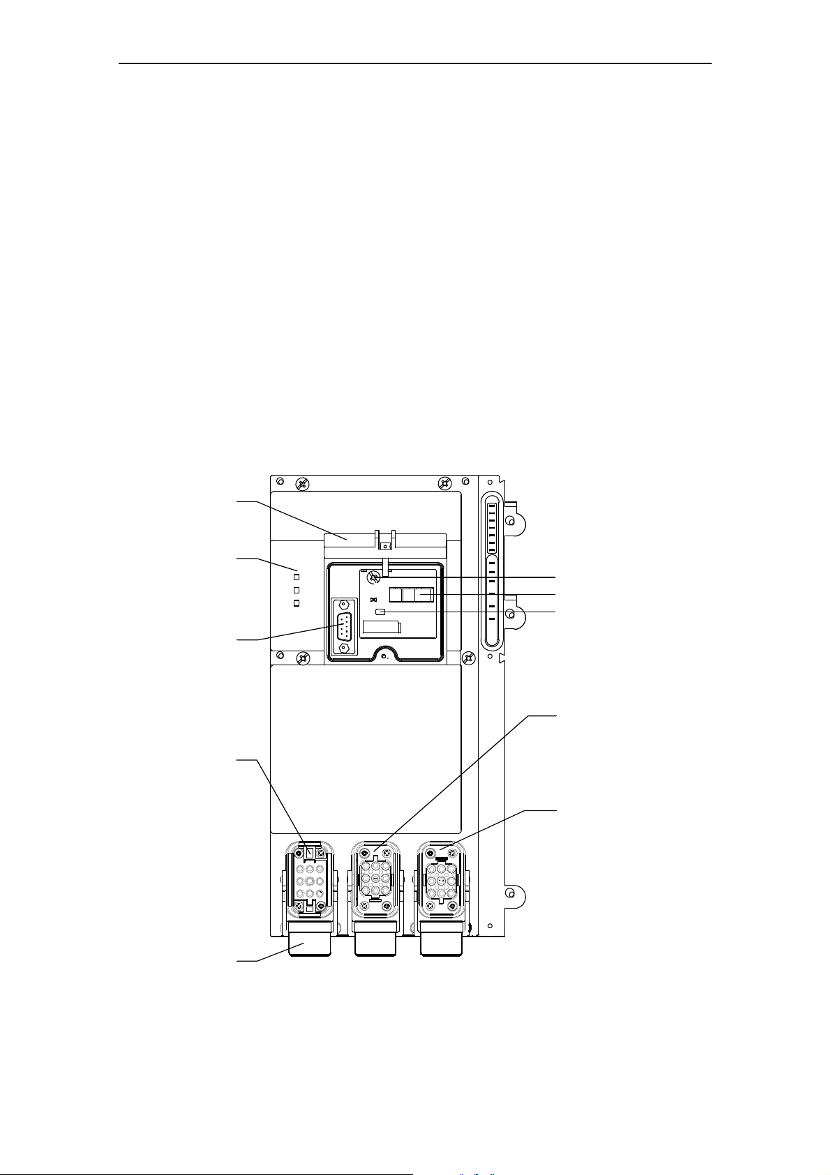
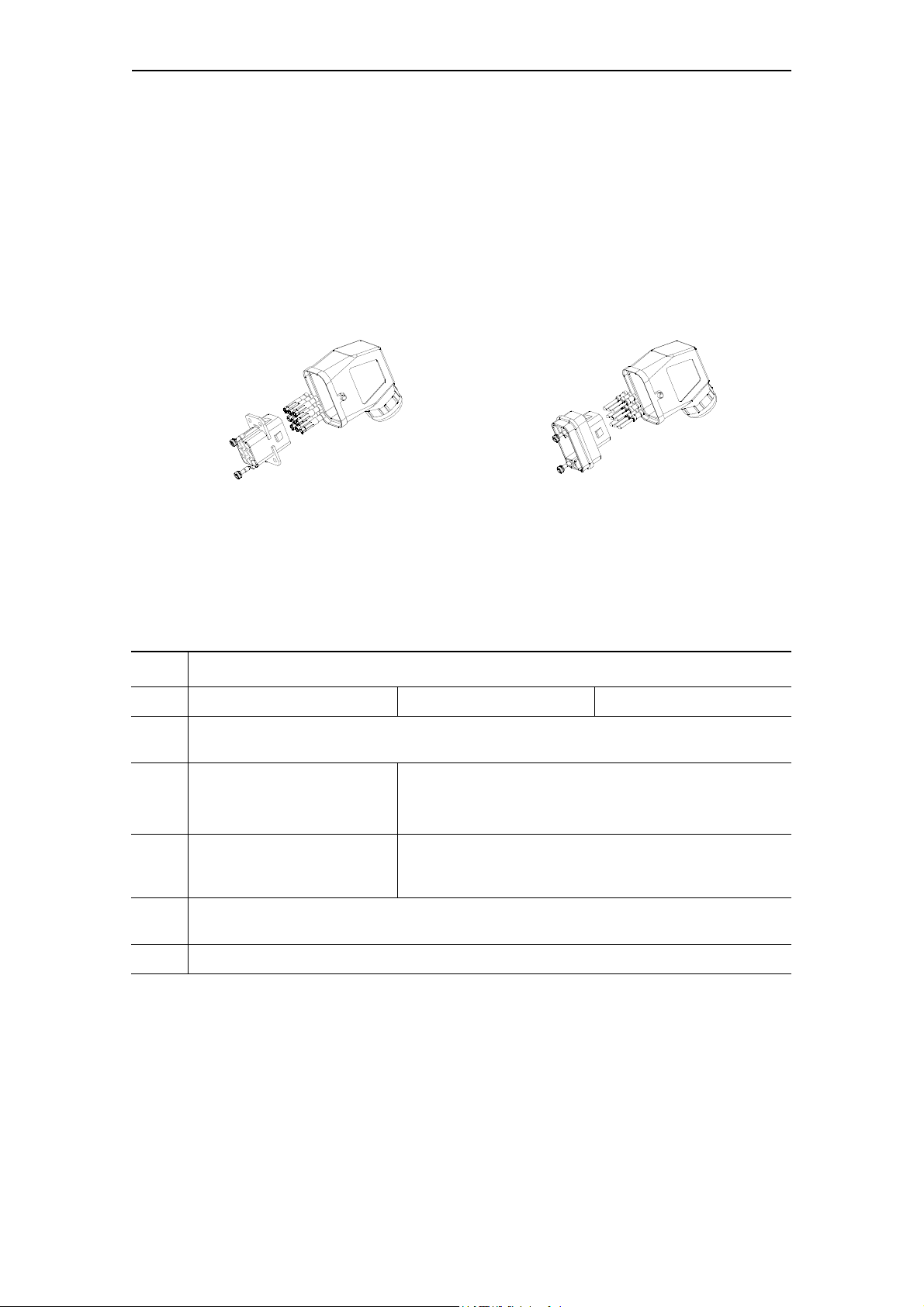
Product Overview
Interlock
DC24V
STATE
Power connector
for feeding
– load supply voltage
– braking voltage (on
versions with a 24 V
DC braking contact)
Circuit-breaker
– Scale for current setting
– Toggle switch
– Test opening
LEDs
– Auxiliary power
–State
Power socket
for connecting
– load
–brake
Power socket
for looping through
– load supply voltage
– braking voltage (on
versions with a 24 V
DC braking contact)
Transparent cover,
open
SUB-D
(for hand-held
controller only!)
1.1 What are the Motor Starters EM 300 DS and EM 300 RS?
Motor starters EM 300 DS/RS
Motor starters EM 300 DS and EM 300 RS are electromechanical motor starters, that can be used on the ET 200X distributed I/O device as expansion
module. Up to six motor starters EM 300 can be added to the basic module.
Characteristics
The motor starters EM 300 DS/RS:
• Are suitable for switching and protecting any three-phase loads up to 5.5 kW
with 400 V AC.
• Are available as either direct starters (EM 300 EDS) or reversing starters
(EM 300 ERS) with adjustment ranges from 0.14 to 0.2 A and 9 to 12 A
respectively.
• Can be equipped with a 24 V DC, max. 3 A, or 500 V DC, max. 0,2 A, braking
contact as an option.
View
The diagram below shows the components of a motor starter EM 300 DS/RS.
SIMATIC - EM 300 Motor Starters
1-2 GWA-4NEB 640070302-05
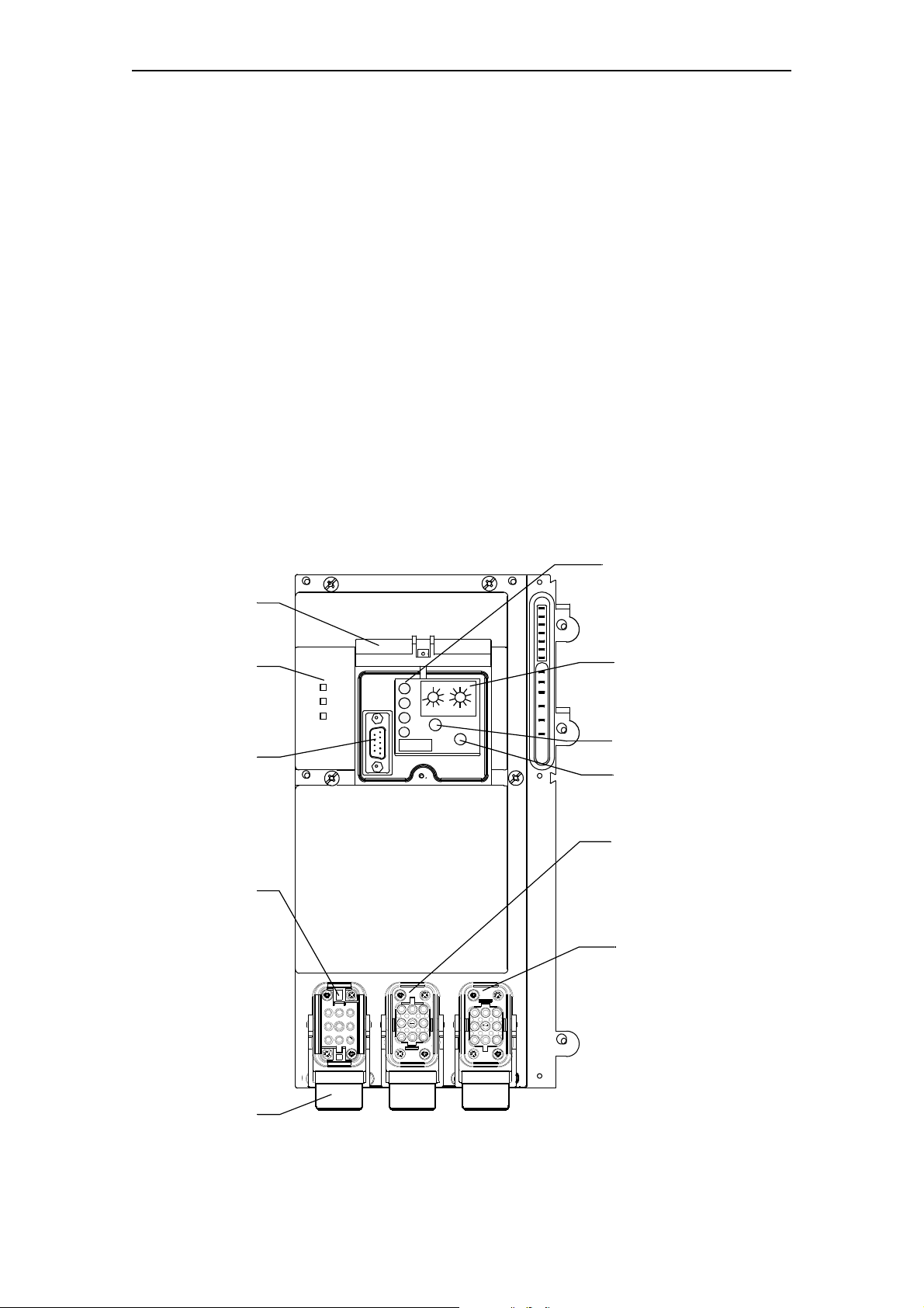
Product Overview
Interlock
TEST/RESET button
DC24V
STATE
LEDs
– Auxiliary power
–State
(from Version 2)
Transparent cover,
open
SUB-D
(for hand-held
controller only!)
Power connector
for feeding
– load supply voltage
– braking voltage (on
versions with a 24 V
DC braking contact)
Power socket
for looping through
– load supply voltage
– braking voltage (on
versions with a 24 V
DC braking contact)
Power socket
for connecting
– load
–brake
LEDs
–READY
–RUN
–FAULT
–OVERLOAD
Rotary encoder switches
1 and 2 for setting the
current
Rotary encoder switch
Tripping REMOTE/LOCAL
Power connector
for feeding
– load supply voltage
– braking voltage (on
versions with a 24 V
DC braking contact)
SUB-D
(for hand-held
controller only!)
1.2 What are the Motor Starters EM 300 EDS and EM 300 ERS?
Motor starters EM 300 EDS/ERS
Motor starters EM 300 EDS and EM 300 ERS are electronic motor starters,
which can be used on the ET 200X distributed I/O device as expansion module.
Up to six motor starters EM 300 can be added to the basic module.
Characteristics
The motor starters EM 300 EDS/ERS:
• Are suitable for switching and protecting any three-phase loads up to 2.2 kW
with 400 V AC.
• Are available as either direct starters (EM 300 EDS) or reversing starters
(EM 300 ERS) with adjustment ranges from 0.6 to 2.18 A and 2.0 to 5.95 A
respectively.
• Can be equipped with a 24 V DC, max. 3 A, or 400 V AC, max. 0.5 A, or
500 V DC, max. 0.2 A braking contact as an option.
View
The diagram below shows the components of a motor starter EM 300 EDS/ERS.
SIMATIC - EM 300 Motor Starters
GWA-4NEB 640070302-05
1-3
Product Overview
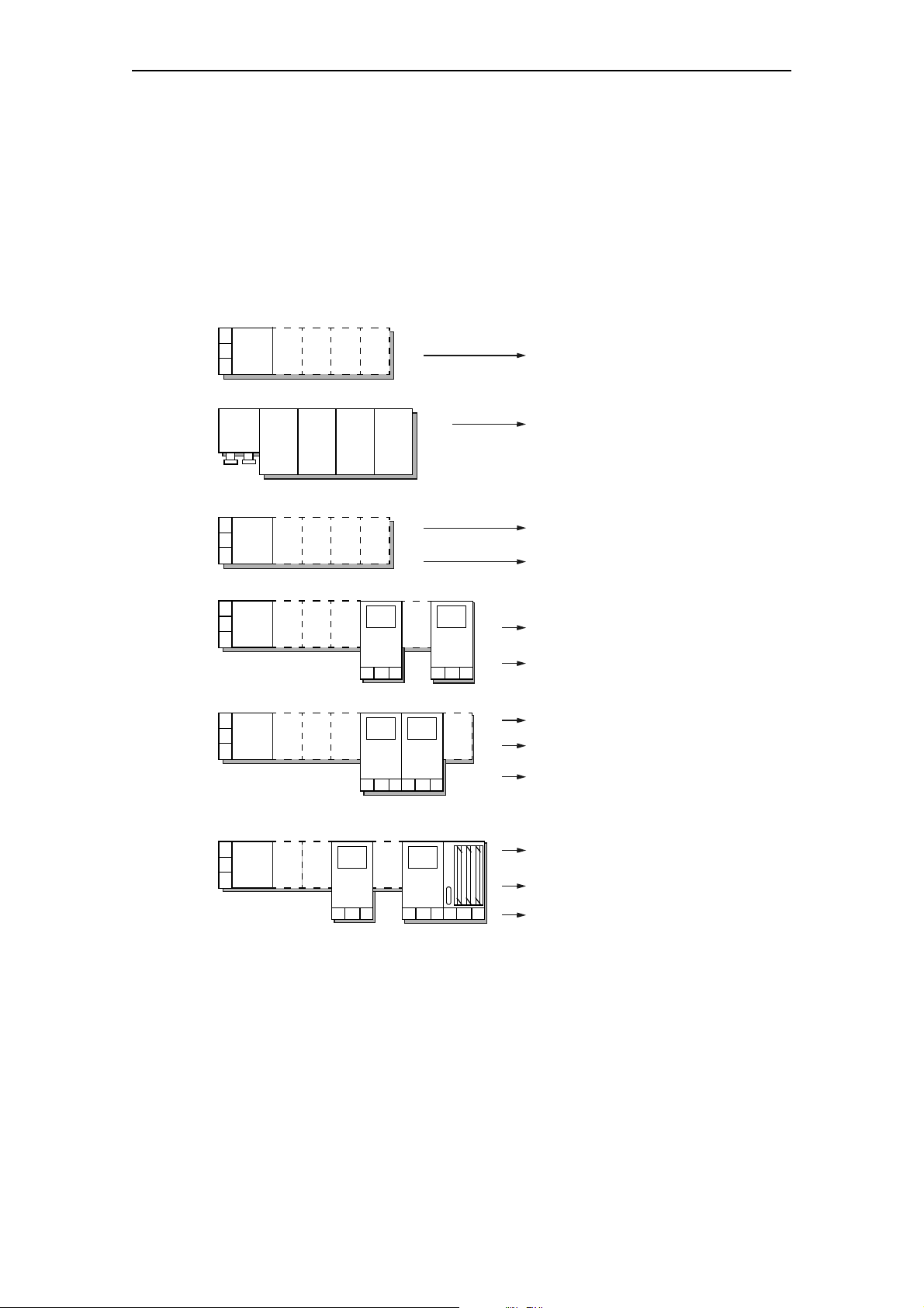
The ET 200X consists of the
following components:
You need the information contained in the following manuals:
ET 200X-DESINA/ECOFAST
ET 200X
ET 200X
Distributed I/O Device
EM 300 Motor Starters
BM 147/CPU Basic module
ET 200X
Distributed I/O Device
EM 300 Motor Starters
ET 200X
Distributed I/O Device
ET 200X
Distributed I/O Device
Distributed I/O Device
+
+
+
EM 300 Motor Starters
+
Frequency Converter
Distributed I/O Device
+
+
BM 147/CPU Basic module
EM
DI
EMDOEM
AI
EM
AO
MS
MS
BM
DI/DO
EM
DI
EMDOEM
AI
EM
AO
BM
DI/DO
EM
143
EM
DI
EMDOEM
AI
EM
AO
BM
147
DI/DO
EM
143
DI/DO
EM
143
DI/DO
EM
143
DI/DO
EM
DI
EMDOEM
AI
MS
BM
147
EM
AO
MS
EM
DI
EM
AI
EM
AO
MS MS
BM
DI/DO
EM-FC
1.3 Guide to the ET 200X Manuals
You are Using the following Components ...
The components of the ET 200X are described in various manuals in the
ET 200X package. The figure below shows possible ET 200X configurations
and the manuals required for them.
Where Do You Find What Information?
The table below will help you get your bearings and find the information you
need quickly. It tells you which manual you need to refer to and which chapter
deals with the topic you are interested in.
1-4 GWA-4NEB 640070302-05
SIMATIC - EM 300 Motor Starters

Manual
Product Overview
Subject
ET 200X configuration options
Installing the ET 200X, motor starters
and frequency converters;
setting the PROFIBUS address;
connecting a terminating resistor
Installing the ET 200X-DESINA/ECOFAST;
setting the PROFIBUS address
BM 147/CPU addressing
Electrical configuration and wiring
of the ET 200X
Electrical configuration and wiring
of the ET 200X-DESINA/ECOFAST
Wiring of motor starters
Wiring of frequency converters
The ET 200X with the BM 147/CPU
with PROFIBUS DP
ET 200X
Distributed
I/O Device
x
x
x
x
x
BM 147/
CPU
Basic
Module
x
x
EM 300
Motor
Starters
x
EM 148-FC
Frequency
Converter
x
Chapter/
Appendix
2
3
3
2
4
4
2
2
3
Commissioning and diagnostics
of the ET 200X
Commissioning and diagnostics
of the ET 200X-DESINA/ECOFAST
Commissioning and diagnostics
of the ET 200X with BM 147/CPU
Commissioning and diagnostics
of the ET 200X with motor starters
Commissioning and diagnostics of the
ET 200X with frequency converters
General technical specifications of
the ET 200X (standards, cerificates
and approvals, EMC, environmental
conditions etc.)
Technical specifications of the basic
and expansion modules with DI, DO,
AI and AO
Technical specifications of the
BM 147/CPU
Technical specifications of the motor
starters
x
x
x
x
x
x
x
x
x
5
5
4
3
3
6
7
5
5
SIMATIC - EM 300 Motor Starters
GWA-4NEB 640070302-05
1-5

Product Overview
Manual
Subject
Functions and technical specifications
of frequency converters
BM 147/CPU cycle and response times
Order numbers of the components
Order numbers of the motor starters
Order numbers of frequency converters
Dimensioned drawings of the basic
modules and digital and analog
expansion modules
Dimensioned drawings of the motor
starters
Dimensioned drawings of frequency
converters
Configuration and parameter assignment frames
Configuration and parameter assignment frames for the BM 147/CPU
ET 200X
Distributed
I/O Device
x
x
x
BM 147/
CPU
Basic
Module
x
x
EM 300
Motor
Starters
x
x
EM 148-FC
Frequency
Converter
x
x
x
Chapter/
Appendix
4
6
A
A
A
C
B
B
C
A
Configuration frame for motor starters
List of STEP 7 operations
Execution times of SFCs
Glossary
x
x
xx
x
C
B
C
Glossary
SIMATIC - EM 300 Motor Starters
1-6 GWA-4NEB 640070302-05

Wiring 2
Section Subject Page
2.1 Rules for Wiring 2-2
2.2 Motor Starters EM 300 without a Braking Contact 2-4
2.2.1 Making up Connecting Cables 2-4
2.2.2 Wiring the Power Connectors 2-5
2.2.3 Electrical Design 2-7
2.3 Motor Starters EM 300 with a 24 V DC Braking Contact 2-8
2.3.1 Making up Connecting Cables 2-8
2.3.2 Wiring the Power Connectors 2-9
2.3.3 Electrical Design 2-11
2.4 Motor Starters EM 300 with a 400 V AC resp.
500 V DC Braking Contact
2.4.1 Making up Connecting Cables 2-12
2.4.2 Wiring the Power Connectors 2-13
2.4.3 Electrical Design 2-15
2-12
SIMATIC - EM 300 Motor Starters
GWA-4NEB 640070302-05
2-1

Wiring
2.1 Rules for Wiring
Warning
Dangerous high voltage! Take care to avoid electric shock and injuries from
burns. Always deenergize the system and the device before carrying out any
work.
Selecting the motor connecting cables
The core cross section of the motor connecting cables must match the given
environmental conditions. The cross section is governed by:
• the nominal current set on the unit,
• the method of cable laying,
• the ambient temperature,
• the insulation material of the motor connecting cable (PVC, rubber).
For PVC motor connecting cables laid in cable ducts, the following maximum
current carrying capacities apply according to environment temperature:
T
= 30 °C 40 °C 45 °C 50 °C 55 °C
env
4 x 1.5 mm
4 x 2.5 mm
4 x 4.0 mm
2
2
2
Wiring power connectors
The rules and procedure for wiring the power connectors apply both to the
electromechanical (
EDS/ERS). Observe the following rules when wiring the power plug:
Current carrying capacity of the connection depending on the
connected core cross-section and the environment temperature
1. 5 m m
Permissible outside diameter of cable
Sealing insert green
Bared length of cores 8 mm
Bared length of cable sheath 20 mm
14 A 12.2 A 11.1 A 9.9 A 8.5 A
19 A 16.5 A 15.0 A 13.5 A 11.6 A
26 A 22.6 A 20.5 A 18.5 A 15.9 A
EM 300 DS/RS) and the electronic motor starter (EM 300
Rules for flexible conductors Data
at T
env
55 °C 40 °C
2.5 mm
4.0 mm
red
white
2
2
2
12 A
20 A
30 A
7.0 ... 10.5 mm
9.0 ... 13.0 mm
11.5 ... 15.5 mm
15 A
25 A
35 A
SIMATIC - EM 300 Motor Starters
2-2 GWA-4NEB 640070302-05

Motor starter EM 300 with braking contact
The 400 V power supply for the motor and the 24 V DC power supply for the
brake are fed to the load through a common cable and connector. There is a danger of voltage overspill if the cable is flattened. Do not therefore connect loads
with degree of protection "extra-low voltage" to the braking circuit.
In order to avoid voltage overspill in case of fault the supply voltage for the
brake must be drawn from a power supply unit with safe electrical isolation
(PELV).
Motor starter EM 300 without braking contact
The braking supply voltage of motor starters without a 24 V braking contact is
internally not looped through. The 24 V DC braking voltage must then be drawn
from the power supply unit again.
Unused connections
Seal unused connections with caps, only then is degree of protection IP 65
guaranteed (order number 3 RK1 902-0CK00 (1 piece) or 3 RK1 902-0CJ00
(10 pieces).
Wiring
SIMATIC - EM 300 Motor Starters
GWA-4NEB 640070302-05
2-3

Wiring
X2
X1
X3
2.2 Motor Starters EM 300 without a Braking Contact
2.2.1 Making up Connecting Cables
Accessories
If you want to make up your own connecting cable for motor starters EM 300
without braking contact, you will need one crimping tool for contact pins/jacks
(alternatively, they can be soldered) and the following components.
Yo u n e ed . . .
For connecting load
supply voltage
One flexible 4-core copper
cable 2.5 mm
(3 conductors + PE)
One set of connectors
• 2.5 mm
• 4.0 mm2:3RK1902-0CB00
—resp.
2
/ 4.0 mm
2
:3RK1902-0CA00
2
For connecting load For looping through
load supply voltage
One flexible 4-core copper
cable 1.5 mm
(3 conductors + PE)
One set of connectors
• 1.5 mm2: 3RK1902-0CE00
• 2.5 mm2: 3RK1902-0CC00
one motor connecting cable
with plug, 4 x 1.5 mm
• 3 m: 3 RK1 902-0CM00
• 5 m: 3 RK1 902-0CP00
• 10 m: 3 RK1 902-0CQ00
2
/ 2.5 mm
2
2
One flexible 4-core copper
cable 2.5 mm
(3 conductors + PE)
One set of connectors
• 2.5 mm2: 3RK1902-0CC00
• 4.0 mm2: 3RK1902-0CD00
resp.
one power connecting cable
with plug and socket
• 6 x 2.5 mm2, 0.12 m:
• 4 x 4.0 mm2, 0.15 m:
2
/ 4.0 mm
3 RK1 902-0CH00
3 RK1 902-0CG00
2
SIMATIC - EM 300 Motor Starters
2-4 GWA-4NEB 640070302-05
2.2.2 Wiring the Power Connectors
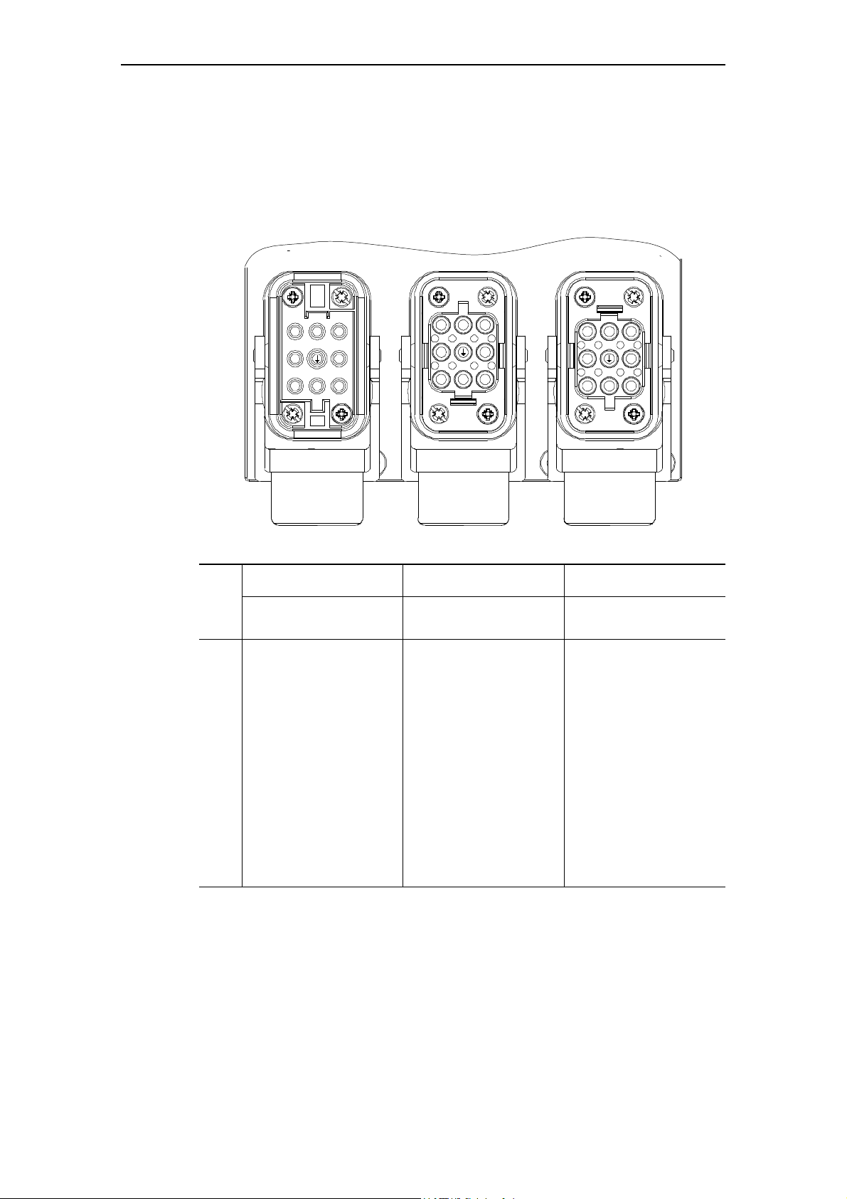
1
2
3
4
5
6
7
8
12
3
45
6
7
8
1
23
4
5
6
7
8
Pinout
The diagram and the table below indicate the pinout of the power connector and
the two power sockets on the motor starter without a braking contact.
Wiring
Coding
Pin-
Plug X1 Socket X2 Socket X3
out
Connecting load
supply voltage
Connecting load Looping through
load supply voltage
1 — Phase 1 —
2 Phase 2 — Phase 2
3 — Phase 3 —
4———
5———
6 Phase 1 — Phase 3
7 — Phase 2 —
8 Phase 3 — Phase 1
PE PE PE
e
To avoid confusion of compact starter power sockets X2 and X3, the mounting
position of X2 is rotated by 180° relative to the mounting position of X3.
SIMATIC - EM 300 Motor Starters
GWA-4NEB 640070302-05
2-5
Wiring
connector shell connector shell
socket insert
jacks contact pins
pin insert
Power socket
• for connecting load supply voltage
Power connector
• for connecting the load
• for looping through the load supply
voltage
Power connectors
The power connectors of a motor starter without a braking contact consist of
the following components:
Installing and wiring power connectors
Install the power connectors of a motor starter without a braking contact as follows. Please note the wiring rules described in Chapter 2.1.
Step Procedure
Socket for X1 Connector for X2 Connector for X3
1 Feed the cable through the gland, the appropriately-sized sealing ring supplied and the
connector shell.
2 Fasten the jacks to the cores
• for phases 1 to 3
•for PE
3 Press the jacks into the
socket insert until they snap
into place.
4 Withdraw the cable sufficiently to be able to screw the socket or pin insert tightly inside
the connector shell with the enclosed screws.
5 Screw the gland tight.
Fasten the contact pins to the cores
• for phases 1 to 3
•for PE
Press the contact pins into the pin insert until they snap
into place.
SIMATIC - EM 300 Motor Starters
2-6 GWA-4NEB 640070302-05
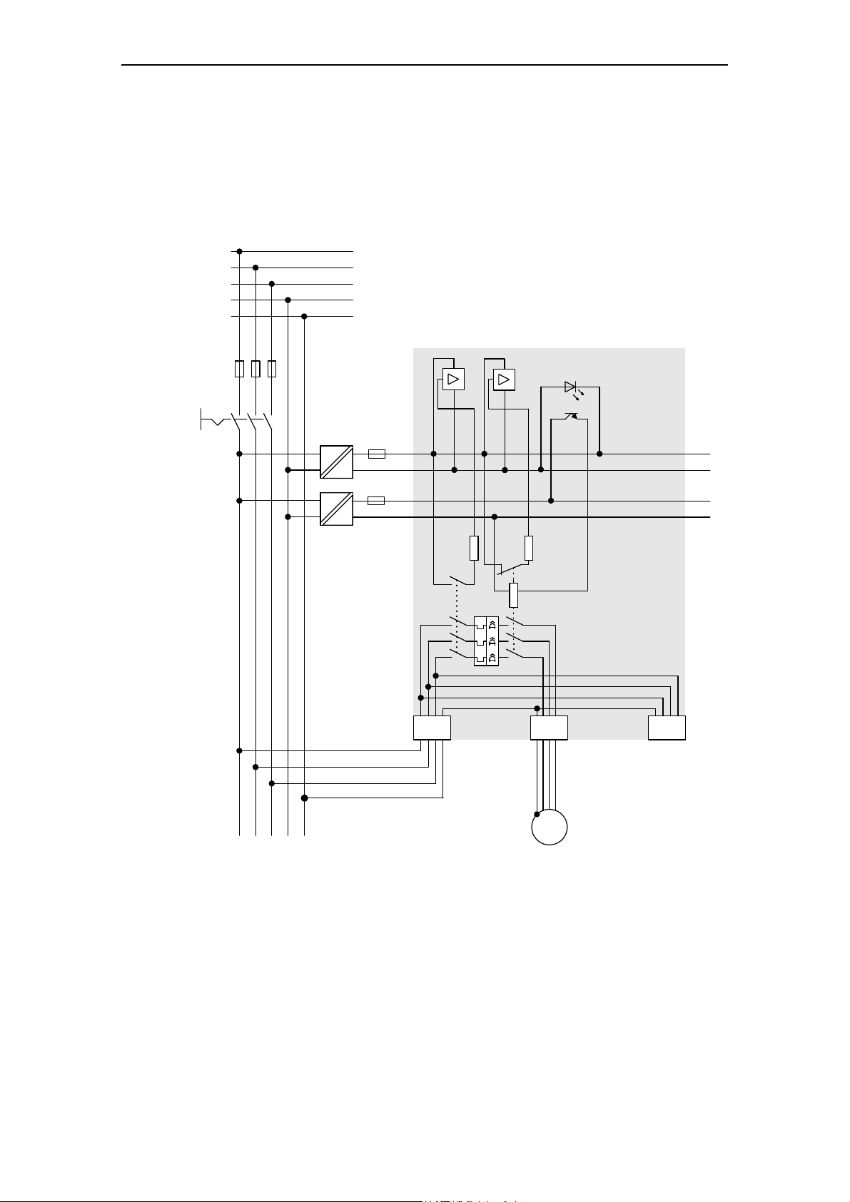
2.2.3 Electrical Design
AC
DC
AC
DC
M
3~
L1
L2
L3
N
PE
1L+
X2 X3X1
1M
2L+
2M
Configuration
The following diagram shows the electrical design of a motor starter EM 300
DS/RS without a braking contact.
Wiring
SIMATIC - EM 300 Motor Starters
GWA-4NEB 640070302-05
2-7

Wiring
X2
X1
X3
2.3 Motor Starters EM 300 with a 24 V DC Braking Contact
2.3.1 Making up Connecting Cables
Accessories
If you want to make up your own connecting cable for motor starters EM 300
with a 24 V DC braking contact, you will need one crimping tool for contact
pins/jacks (alternatively, they can be soldered) and the following components.
Yo u n e ed . . .
For connecting load
supply voltage
One flexible 6-core copper
cable 2.5 mm
2
/ (4.0 mm2)
(3 conductors + PE + 24 V + M)
One set of connectors
• 2.5 mm
• 4.0 mm
2
:3RK1902-0CA00
2
:3RK1902-0CB00
For connecting load
with a brake 24 V DC
One flexible 6-core copper
cable 1.5 mm2 / 2.5 mm
(3 conductors + PE + 24 V + M)
One set of connectors
• 1.5 mm
• 2.5 mm
— resp.
one motor connecting cable
with plug, 6 x 1.5 mm
• 3 m:3 RK1 902-0CN00
• 5 m:3 RK1 902-0CR00
• 10 m:3 RK1 902-0CS00
2
2
: 3RK1902-0CE00
2
: 3RK1902-0CC00
2
For looping through
load supply voltage
and brake voltage
One flexible 6-core copper
cable 2.5 mm2 / (4.0 mm2)
(3 conductors + PE + 24 V + M)
One set of connectors
• 2.5 mm
• 4.0 mm
2
: 3RK1902-0CC00
2
: 3RK1902-0CD00
resp.
one power connecting cable
with plug and socket,
6 x 2.5 mm
2
• 0.12 m: 3 RK1 902-0CH00
SIMATIC - EM 300 Motor Starters
2-8 GWA-4NEB 640070302-05

2.3.2 Wiring the Power Connectors
1
2
3
4
5
6
7
8
12
3
45
6
7
8
1
23
4
5
6
7
8
Pinout
The diagram and the table below indicate the pinout of the power connector and
the two power sockets on a motor starter with a 24 V DC braking contact.
Wiring
Pin-
Plug X1 Socket X2 Socket X3
out
Connecting load
supply voltage
Connecting load
with brake
Looping through load
supply voltage and
brake voltage
1 — Phase 1 —
2 Phase 2 — Phase 2
3 — Phase 3 —
4 GND GND + 24 V DC
5 + 24 V DC + GND
6 Phase 1 — Phase 3
7 — Phase 2 —
8 Phase 3 — Phase 1
PE PE PE
e
SIMATIC - EM 300 Motor Starters
GWA-4NEB 640070302-05
2-9

Wiring
connector shell connector shell
socket insert
jacks contact pins
pin insert
Power socket
• for connecting load supply voltage
Power connector
• for connecting the load with a brake
• for looping through the load supply
voltage and the braking voltage
Power connectors
The power connectors of a motor starter EM 300 with a 24 V DC braking contact consist of the following components:
Installing and wiring power connectors
Install the power connectors of a motor starter with a 24 V DC braking contact
as follows. Please note the wiring rules described in Chapter 2.1
Step Procedure
Socket for X2 Connector for X2 Connector for X3
1 Feed the cable through the gland, the appropriately-sized sealing ring supplied and the
connector shell.
2 Fasten the jacks to the cores
• for phases 1 to 3
• for the brake
•for PE
3 Press the jacks into the
socket insert until they snap
into place.
4 Withdraw the cable sufficiently to be able to screw the socket or pin insert tightly inside the
connector shell with the enclosed screws.
5 Screw the gland tight.
Fasten the contact pins to the cores
• for phases 1 to 3
• for the brake
•for PE
Press the contact pins into the pin insert until they snap
into place.
SIMATIC - EM 300 Motor Starters
2-10 GWA-4NEB 640070302-05
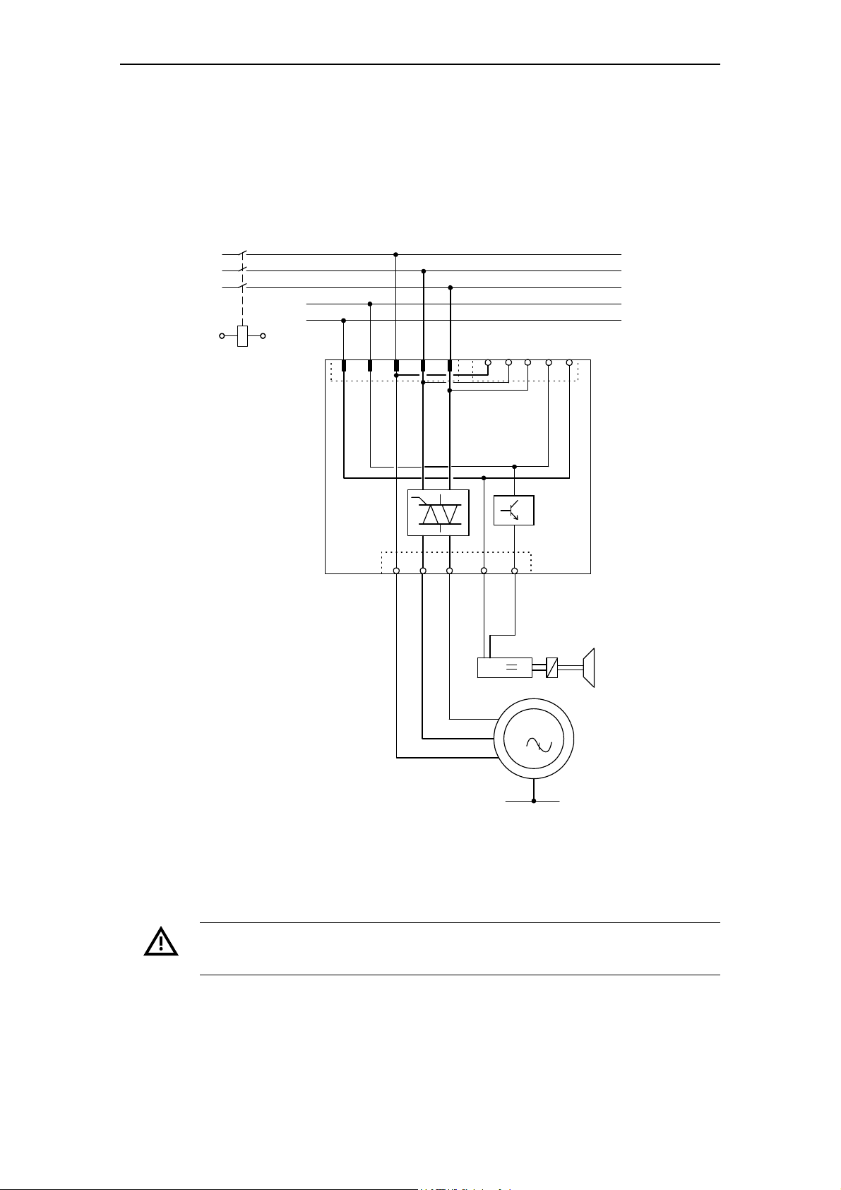
2.3.3 Electrical Design
Motor with 24 V DC brake
6
2
8
X1
X3
8
2
6
1
7
3
X2
4
5
1 W
1 V
1 U
P E
5
4
54
M
3
+24 V DC
M
L1
L2
L3
K1
A1 A2
Galvanic
isolation
Suggested circuit
The following diagram suggests one way of controlling the motor with a
24 V DC brake via an electronic compact starter EM 300 EDS/ERS.
Wiring
Galvanic isolation
An external isolating contactor must be fitted to ensure galvanic isolation from
the power supply system!
SIMATIC - EM 300 Motor Starters
GWA-4NEB 640070302-05
2-11
 Loading...