

Page 1

___________________
___________
___________
___________________
___________
___________________
___________________
___________________
___________
___________________
___________________
___________________
___________________
___________________
___________________
___________________
___________________
___________________
___________________
___________________
___________________
SIMATIC
PCS 7 process control system
CPU 410 Process Automation/CPU
410 SMART
System Manual
05/2017
A5E31622160
Preface
1
Introduction to the CPU 410
2
Configuration of the CPU
410
3
PROFIBUS DP
4
PROFINET IO
5
I/O configuration variants
6
System and operating states
of the CPU 410
7
Link-up and update
8
Special functions of the CPU
410
9
Time synchronization and
time stamping
10
Plant changes in RUN - CiR
11
Plant changes during
redundant operation - H-CiR
12
Replacement of failed
components during
redundant operation
13
Synchronization modules
14
System expansion card
15
Technical data
16
Properties and technical
specifications of CPU 410
SMART
17
Supplementary information
18
Characteristic values of
redundant automation
systems
A
Function and communication
modules that can be used in
a redundant configuration
B
Connection examples for
redundant I/Os
C
-AC
Page 2

Siemens AG
Division Process Industries
Postfach 48 48
90026 NÜRNBERG
GERMANY
A5E31622160-AC
Ⓟ
Copyright © Siemens AG 2017.
All rights reserved
Legal information
Warning notice system
DANGER
indicates that death or severe personal injury will result if proper precautions are not taken.
WARNING
indicates that death or severe personal injury may result if proper precautions are not taken.
CAUTION
indicates that minor personal injury can result if proper precautions are not taken.
NOTICE
indicates that property damage can result if proper precautions are not taken.
Qualified Personnel
personnel qualified
Proper use of Siemens products
WARNING
Siemens products may only be used for the applications described in the catalog and in the relevant technical
maintenance are required to ensure that the products operate safely and without any problems. The permissible
ambient conditions must be complied with. The information in the relevant documentation must be observed.
Trademarks
Disclaimer of Liability
This manual contains notices you have to observe in order to ensure your personal safety, as well as to prevent
damage to property. The notices referring to your personal safety are highlighted in the manual by a safety alert
symbol, notices referring only to property damage have no safety alert symbol. These notices shown below are
graded according to the degree of danger.
If more than one degree of danger is present, the warning notice representing the highest degree of danger will
be used. A notice warning of injury to persons with a safety alert symbol may also include a warning relating to
property damage.
The product/system described in this documentation may be operated only by
task in accordance with the relevant documentation, in particular its warning notices and safety instructions.
Qualified personnel are those who, based on their training and experience, are capable of identifying risks and
avoiding potential hazards when working with these products/systems.
Note the following:
documentation. If products and components from other manufacturers are used, these must be recommended
or approved by Siemens. Proper transport, storage, installation, assembly, commissioning, operation and
All names identified by ® are registered trademarks of Siemens AG. The remaining trademarks in this publication
may be trademarks whose use by third parties for their own purposes could violate the rights of the owner.
We have reviewed the contents of this publication to ensure consistency with the hardware and software
described. Since variance cannot be precluded entirely, we cannot guarantee full consistency. However, the
information in this publication is reviewed regularly and any necessary corrections are included in subsequent
editions.
for the specific
and Drives
06/2017 Subject to change
Page 3

Table of contents
1 Preface ................................................................................................................................................. 17
2 Introduction to the CPU 410 .................................................................................................................. 23
3 Configuration of the CPU 410 ................................................................................................................ 35
4 PROFIBUS DP ..................................................................................................................................... 49
5 PROFINET IO ....................................................................................................................................... 51
6 I/O configuration variants ...................................................................................................................... 55
1.1 Preface .................................................................................................................................... 17
1.2 Security information ................................................................................................................ 20
1.3 Documentation ........................................................................................................................ 21
2.1 Area of application of the CPU 410 in SIMATIC PCS 7 ......................................................... 23
2.2 Possible applications .............................................................................................................. 25
2.3 The CPU 410 basic system for stand-alone operation ........................................................... 27
2.4 The basic system for redundant operation ............................................................................. 28
2.5 Rules for H station assembly .................................................................................................. 30
2.6 I/O for the CPU 410 ................................................................................................................ 30
2.7 I/O configuration variants of the fault-tolerant system ............................................................ 31
2.8 Configuration tools (STEP 7 HW Config, SIMATIC PCS 7) ................................................... 31
2.9 The SIMATIC PCS 7 project ................................................................................................... 31
2.9.1 Scaling and licensing (scaling concept) .................................................................................. 32
3.1 Operator controls and indicators on the CPU 410 .................................................................. 35
3.2 CPU 410 monitoring functions ................................................................................................ 39
3.3 Status and error displays ........................................................................................................ 41
3.4 PROFIBUS DP interface (X1) ................................................................................................. 45
3.5 PROFINET IO interfaces (X5, X8) .......................................................................................... 45
3.6 Summary of parameters for CPU 410 .................................................................................... 48
4.1 CPU 410 as PROFIBUS DP master ....................................................................................... 49
4.2 Diagnostics of the CPU 410 as PROFIBUS DP master ......................................................... 49
5.1 Introduction ............................................................................................................................. 51
5.2 PROFINET IO systems ........................................................................................................... 52
5.3 Device replacement without exchangeable medium / ES ...................................................... 53
6.1 Stand-alone operation............................................................................................................. 55
CPU 410 Process Automation/CPU 410 SMART
System Manual, 05/2017, A5E31622160-AC
3
Page 4

Table of contents
7 System and operating states of the CPU 410 ....................................................................................... 101
8 Link-up and update .............................................................................................................................. 119
6.2 Fail-safe operation ................................................................................................................. 58
6.3 Fault-tolerant automation systems (redundancy operation) .................................................. 61
6.3.1 Redundant SIMATIC automation systems ............................................................................. 61
6.3.2 Increase of plant availability, reaction to errors ..................................................................... 62
6.4 Introduction to the I/O link to fault-tolerant system ................................................................ 65
6.5 Using single-channel switched I/O ......................................................................................... 66
6.6 Versions of I/O connection to the PROFINET IO interface .................................................... 73
6.6.1 Use of I/O connected to the PROFINET IO interface, system redundancy ........................... 73
6.6.2 Redundant I/O in an ET 200SP HA ....................................................................................... 76
6.7 Connection of two-channel I/O to the PROFIBUS DP interface ............................................ 80
6.7.1 Connecting redundant I/O ...................................................................................................... 80
6.7.2 Signal modules for redundancy ............................................................................................. 83
6.7.3 Evaluating the passivation status ........................................................................................... 97
6.8 Media redundancy ................................................................................................................. 97
7.1 CPU 410 operating modes ................................................................................................... 101
7.1.1 RUN mode ........................................................................................................................... 101
7.1.2 STOP mode ......................................................................................................................... 102
7.1.3 STARTUP mode .................................................................................................................. 103
7.1.4 HOLD mode ......................................................................................................................... 104
7.1.5 LINK-UP and UPDATE modes ............................................................................................ 105
7.1.6 ERROR-SEARCH mode ...................................................................................................... 105
7.1.7 DEFECTIVE state ................................................................................................................ 106
7.2 System states of the redundant CPU 410 ........................................................................... 107
7.2.1 Introduction .......................................................................................................................... 107
7.2.2 The system states of the fault-tolerant system .................................................................... 109
7.2.3 Displaying and changing the system state of a fault-tolerant system .................................. 110
7.2.4 System status change from the STOP system state ........................................................... 110
7.2.5 System status change from the standalone mode system status ....................................... 111
7.2.6 System status change from the redundant system state ..................................................... 111
7.2.7 System diagnostics of a fault-tolerant system ..................................................................... 112
7.3 Self-test ................................................................................................................................ 114
7.4 Performing a memory reset ................................................................................................. 117
8.1 Effects of link-up and updating ............................................................................................. 119
8.2 Link-up and update via an ES command ............................................................................. 120
8.3 Time monitoring ................................................................................................................... 120
8.3.1 Time response ..................................................................................................................... 123
8.3.2 Determining the monitoring times ........................................................................................ 123
8.3.3 Performance values for link-up and update ......................................................................... 130
8.3.4 Influences on time response ................................................................................................ 130
8.4 Special features in link-up and update operations ............................................................... 131
CPU 410 Process Automation/CPU 410 SMART
4 System Manual, 05/2017, A5E31622160-AC
Page 5

Table of contents
9 Special functions of the CPU 410 ........................................................................................................ 133
10 Time synchronization and time stamping ............................................................................................. 151
11 Plant changes in RUN - CiR ................................................................................................................ 155
9.1 Security functions of the CPU 410 ........................................................................................ 133
9.2 Security levels ....................................................................................................................... 134
9.3 Security event logging........................................................................................................... 136
9.4 Field Interface Security ......................................................................................................... 139
9.5 Access-protected blocks ....................................................................................................... 139
9.6 Retentive load memory ......................................................................................................... 140
9.7 Type update with interface change in RUN .......................................................................... 141
9.8 Resetting the CPU 410 to delivery condition (reset to factory setting) ................................. 142
9.9 Reset during operation.......................................................................................................... 143
9.10 Response to fault detection .................................................................................................. 144
9.11 Reading service data ............................................................................................................ 145
9.12 Updating firmware in stand-alone operation ......................................................................... 146
9.13 Updating firmware in redundant mode.................................................................................. 148
11.1 Motivation for CiR via PROFINET IO .................................................................................... 155
11.2 Permitted changes over PROFINET IO ................................................................................ 157
11.3 Procedure for PROFINET IO ................................................................................................ 158
11.3.1 Overview ............................................................................................................................... 158
11.3.2 Add IO devices or I/O modules ............................................................................................. 159
11.3.3 Rebuild hardware when adding an IO device ....................................................................... 160
11.3.4 Change process image partition assignment ....................................................................... 160
11.3.5 Re-configuring existing I/O modules in IO devices ............................................................... 161
11.3.6 Replacing IO devices or I/O modules ................................................................................... 161
11.4 Re-configuring I/O modules and ports in IO devices ............................................................ 161
11.4.1 Requirements for Reconfiguration ........................................................................................ 161
11.4.2 I/O module response to re-configuration .............................................................................. 162
11.4.3 CPU response during reconfiguration ................................................................................... 162
11.4.4 Reconfiguration Procedure ................................................................................................... 164
11.4.4.1 Using a Previously Unused Channel .................................................................................... 164
11.4.4.2 Reconfiguring an already used channel. .............................................................................. 164
11.4.4.3 Delete an already used channel. .......................................................................................... 166
11.4.4.4 Change the update time ....................................................................................................... 166
11.5 Motivation for CiR via PROFINET DP .................................................................................. 166
11.6 Permitted changes over PROFIBUS DP .............................................................................. 168
11.7 CiR objects and CiR modules for PROFINET DP ................................................................ 170
11.7.1 Basic Requirements .............................................................................................................. 170
11.7.2 Types of CiR Elements ......................................................................................................... 170
11.7.3 CiR Elements and I/O Address Areas .................................................................................. 171
11.8 Procedure for PROFIBUS DP ............................................................................................... 172
CPU 410 Process Automation/CPU 410 SMART
System Manual, 05/2017, A5E31622160-AC
5
Page 6

Table of contents
12 Plant changes during redundant operation - H-CiR ............................................................................... 197
11.8.1 Basic Procedures in STOP Mode ........................................................................................ 172
11.8.1.1 Overview .............................................................................................................................. 172
11.8.1.2 Defining CiR Elements ......................................................................................................... 174
11.8.1.3 Deleting CiR Elements ......................................................................................................... 176
11.8.2 Basic Procedure in RUN Mode ............................................................................................ 177
11.8.2.1 Overview .............................................................................................................................. 177
11.8.2.2 add slaves or modules ......................................................................................................... 178
11.8.2.3 Reconfigure the hardware when adding a slave .................................................................. 179
11.8.2.4 change process image partition assignment ....................................................................... 179
11.8.2.5 reconfigure existing modules in ET200M / ET200iSP stations ............................................ 179
11.8.2.6 Undo previous changes (Undo function): ............................................................................ 180
11.8.2.7 Replacing Slaves or Modules .............................................................................................. 180
11.8.2.8 Using CiR Elements in RUN Mode ...................................................................................... 181
11.8.2.9 Undoing Previous Changes ................................................................................................. 184
11.9 Reconfigure existing modules in ET200M / ET200iSP stations .......................................... 185
11.9.1 Requirements for Reconfiguration ....................................................................................... 185
11.9.2 Module Response During a Reconfiguration ....................................................................... 186
11.9.3 CPU response during reconfiguration .................................................................................. 186
11.9.4 Reconfiguration Procedure .................................................................................................. 188
11.9.4.1 Using a Previously Unused Channel ................................................................................... 188
11.9.4.2 Reconfiguring an already used channel. ............................................................................. 188
11.9.4.3 Delete an already used channel. ......................................................................................... 189
11.10 Notes on Reconfiguration in RUN Mode Depending on the I/O .......................................... 190
11.10.1 Modules in IO devices of the type ET 200SP HA ................................................................ 190
11.10.2 DP and PA Slaves ............................................................................................................... 190
11.10.3 Modules in ET 200M Modular Slaves .................................................................................. 193
11.10.4 Modules in ET200iSP Modular Slaves ................................................................................ 194
11.11 Effects on the process when re-configuring in RUN ............................................................ 194
11.11.1 Effects on Operating System Functions During the CiR Synchronization Time .................. 194
11.11.2 Behavior of the CPU after download of the configuration in RUN ....................................... 195
11.11.2.1 Overview .............................................................................................................................. 195
11.11.2.2 Error displays ....................................................................................................................... 196
12.1 The H-CiR wizard ................................................................................................................. 197
12.2 Replacing central components ............................................................................................. 198
12.3 Addition of interface modules ............................................................................................... 199
12.4 Motivation for H-CiR via PROFINET IO ............................................................................... 201
12.5 Permitted changes over PROFINET IO ............................................................................... 202
12.6 Motivation for H-CiR via PROFIBUS DP ............................................................................. 204
12.7 Permitted changes over PROFIBUS DP ............................................................................. 205
12.8 Adding components ............................................................................................................. 207
12.8.1 Modify hardware................................................................................................................... 207
12.8.2 Change hardware configuration offline ................................................................................ 208
12.8.3 Opening the H-CiR wizard ................................................................................................... 209
12.8.4 Modify and download the user program .............................................................................. 210
12.8.5 Use of free channels on an existing module ........................................................................ 211
CPU 410 Process Automation/CPU 410 SMART
6 System Manual, 05/2017, A5E31622160-AC
Page 7

Table of contents
13 Replacement of failed components during redundant operation ........................................................... 223
14 Synchronization modules .................................................................................................................... 239
15 System expansion card ....................................................................................................................... 251
16 Technical data .................................................................................................................................... 253
17 Properties and technical specifications of CPU 410 SMART ................................................................ 283
12.9 Removal of components ....................................................................................................... 211
12.9.1 Change hardware configuration offline ................................................................................. 212
12.9.2 Modify and download the user program ............................................................................... 213
12.9.3 Opening the H-CiR wizard .................................................................................................... 214
12.9.4 Modify hardware ................................................................................................................... 215
12.9.5 Removal of interface modules .............................................................................................. 216
12.10 Editing CPU parameters ....................................................................................................... 217
12.10.1 Editing CPU parameters ....................................................................................................... 217
12.10.2 Changing CPU parameters offline ........................................................................................ 219
12.10.3 Opening the H-CiR wizard .................................................................................................... 219
12.11 Re-parameterization of a module ......................................................................................... 220
12.11.1 Re-configuring a module/PDEV submodule ......................................................................... 220
12.11.2 Editing parameters offline ..................................................................................................... 221
12.11.3 Opening the H-CiR wizard .................................................................................................... 221
13.1 Replacement of central components .................................................................................... 223
13.1.1 Replacement of a CPU during redundant operation ............................................................. 223
13.1.2 Replacement of a power supply module............................................................................... 225
13.1.3 Replacement of an input/output module or function module ................................................ 226
13.1.4 Replacement of a communication module............................................................................ 227
13.1.5 Replacement of synchronization module or fiber-optic cable ............................................... 228
13.1.6 Replacement of an IM 460 and IM 461 interface module ..................................................... 231
13.2 Replacement of components of the distributed I/O on PROFINET IO ................................. 231
13.2.1 Replacement of a PROFINET IO device .............................................................................. 231
13.2.2 Replacement of PROFINET IO cables ................................................................................. 232
13.3 Replacement of components of the distributed I/O on PROFIBUS DP ................................ 233
13.3.1 Replacement of a PROFIBUS DP master ............................................................................ 234
13.3.2 Replacement of a redundant PROFIBUS DP interface module ........................................... 236
13.3.3 Replacement of a PROFIBUS DP slave ............................................................................... 236
13.3.4 Replacement of PROFIBUS DP cables ................................................................................ 237
14.1 Synchronization modules for the CPU 410. .......................................................................... 239
14.2 Installation of fiber-optic cables ............................................................................................ 243
14.3 Selecting fiber-optic cables ................................................................................................... 245
15.1 Variants of the system expansion card ................................................................................. 251
16.1 Technical specifications of CPU 410-5H; (6ES7410-5HX08-0AB0) ..................................... 253
16.2 Technical specifications of CPU 410E (6ES7410-5HM08-0AB0) ........................................ 263
16.3 Technical specifications of the system expansion card ........................................................ 273
17.1 CPU 410 SMART .................................................................................................................. 283
17.2 Technical specifications of the CPU 410 SMART; (6ES7 410-5HN08-0AB0) ...................... 285
CPU 410 Process Automation/CPU 410 SMART
System Manual, 05/2017, A5E31622160-AC
7
Page 8

Table of contents
18 Supplementary information .................................................................................................................. 297
17.3 Technical specifications of the SEC PO 800 ....................................................................... 295
18.1 Supplementary information on PROFIBUS DP ................................................................... 297
18.2 Supplementary information on diagnostics of the CPU 410 as PROFIBUS DP master ...... 298
18.3 System status lists for PROFINET IO .................................................................................. 301
18.4 Configuring with STEP 7 ...................................................................................................... 302
18.4.1 Rules for arranging fault-tolerant station components ......................................................... 302
18.4.2 Configuring hardware ........................................................................................................... 303
18.4.3 Assigning parameters to modules in a fault-tolerant station ................................................ 304
18.4.4 Recommendations for setting CPU parameters, fixed settings ........................................... 304
18.4.5 Networking configuration ..................................................................................................... 305
18.5 The STEP 7 user program ................................................................................................... 306
18.5.1 The user program................................................................................................................. 306
18.6 Programming device functions in STEP 7 ........................................................................... 308
18.7 Communication services ...................................................................................................... 308
18.7.1 Overview of communication services................................................................................... 308
18.7.2 PG communication ............................................................................................................... 310
18.7.3 OP communication ............................................................................................................... 310
18.7.4 S7 communication ............................................................................................................... 310
18.7.5 S7 routing ............................................................................................................................. 312
18.7.6 Data set routing .................................................................................................................... 316
18.7.7 SNMP network protocol ....................................................................................................... 317
18.7.8 Open Communication Via Industrial Ethernet ...................................................................... 318
18.8 Basics and terminology of fault-tolerant communication ..................................................... 321
18.9 Usable networks................................................................................................................... 325
18.10 Communication via S7 connections ..................................................................................... 325
18.10.1 Communication via S7 connections - one-sided mode........................................................ 326
18.10.2 Communication via redundant S7 connections ................................................................... 328
18.10.3 Communication via point-to-point CP on the ET 200M ....................................................... 329
18.10.4 Custom connection to single-channel systems .................................................................... 331
18.11 Communication via fault-tolerant S7 connections ................................................................ 332
18.11.1 Communication between fault-tolerant systems .................................................................. 334
18.11.2 Communication between fault-tolerant systems and a fault-tolerant CPU .......................... 337
18.11.3 Communication between fault-tolerant systems and PCs ................................................... 338
18.12 Consistent data .................................................................................................................... 340
18.12.1 Consistency of communication blocks and functions .......................................................... 340
18.12.2 Consistency rules for SFB 14 "GET" or read variable, and SFB 15 "PUT" or write
variable ................................................................................................................................. 340
18.12.3 Consistent reading and writing of data from and to DP standard slaves/IO devices ........... 341
18.13 Link-
up and update sequence .............................................................................................. 343
18.13.1 Link-up sequence ................................................................................................................. 346
18.13.2 Update sequence ................................................................................................................. 347
18.13.3 Switch to CPU with modified configuration .......................................................................... 351
18.13.4 Disabling of link-up and update ............................................................................................ 352
18.14 The user program................................................................................................................. 353
CPU 410 Process Automation/CPU 410 SMART
8 System Manual, 05/2017, A5E31622160-AC
Page 9

Table of contents
A Characteristic values of redundant automation systems ...................................................................... 379
B Function and communication modules that can be used in a redundant configuration .......................... 389
C Connection examples for redundant I/Os ............................................................................................. 391
18.15 Other options for connecting redundant I/Os ........................................................................ 354
18.16 CPU 410 cycle and reaction times ........................................................................................ 357
18.16.1 Cycle time ............................................................................................................................. 357
18.16.2 Calculating the cycle time ..................................................................................................... 359
18.16.3 Cycle load due to communication ......................................................................................... 362
18.16.4 Response time ...................................................................................................................... 364
18.16.5 Calculating cycle and response times .................................................................................. 369
18.16.6 Examples of calculating the cycle and response times ........................................................ 370
18.16.7 Interrupt response time ......................................................................................................... 373
18.16.8 Example of calculation of the interrupt response time .......................................................... 375
18.16.9 Reproducibility of delay and watchdog interrupts ................................................................. 376
18.17 Runtimes of the FCs and FBs for redundant I/Os ................................................................ 377
A.1 Basic concepts ...................................................................................................................... 379
A.2 Comparison of MTBF for selected configurations ................................................................ 383
A.2.1 System configurations with redundant CPU 410 .................................................................. 383
A.2.2 System configurations with distributed I/Os .......................................................................... 384
A.2.3 Comparison of system configurations with standard and fault-tolerant communication ...... 388
C.1 MTA terminal modules (Marshalled Termination Assemblies) ............................................. 391
C.2 Interconnection of output modules ........................................................................................ 391
C.3 8-channel HART analog input MTA ...................................................................................... 393
C.4 8-channel HART analog output MTA .................................................................................... 394
C.5 SM 321; DI 16 x DC 24 V, 6ES7 321–1BH02–0AA0 ............................................................ 395
C.6 SM 321; DI 32 x DC 24 V, 6ES7 321–1BL00–0AA0 ............................................................. 396
C.7 SM 321; DI 16 x AC 120/230V, 6ES7 321–1FH00–0AA0 .................................................... 397
C.8 SM 321; DI 8 x AC 120/230 V, 6ES7 321–1FF01–0AA0 ...................................................... 398
C.9 SM 321; DI 16 x DC 24V, 6ES7 321–7BH00–0AB0 ............................................................. 399
C.10 SM 321; DI 16 x DC 24V, 6ES7 321–7BH01–0AB0 ............................................................. 400
C.11 SM 326; DO 10 x DC 24V/2A, 6ES7 326–2BF01–0AB0 ...................................................... 401
C.12 SM 326; DI 8 x NAMUR, 6ES7 326–1RF00–0AB0 ............................................................... 402
C.13 SM 326; DI 24 x DC 24 V, 6ES7 326–1BK00–0AB0 ............................................................ 403
C.14 SM 421; DI 32 x UC 120 V, 6ES7 421–1EL00–0AA0 ........................................................... 404
C.15 SM 421; DI 16 x DC 24 V, 6ES7 421–7BH01–0AB0 ............................................................ 405
C.16 SM 421; DI 32 x DC 24 V, 6ES7 421–1BL00–0AB0 ............................................................. 406
C.17 SM 421; DI 32 x DC 24 V, 6ES7 421–1BL01–0AB0 ............................................................. 407
C.18 SM 322; DO 8 x DC 24 V/2 A, 6ES7 322–1BF01–0AA0 ...................................................... 408
C.19 SM 322; DO 32 x DC 24 V/0,5 A, 6ES7 322–1BL00–0AA0 ................................................. 409
CPU 410 Process Automation/CPU 410 SMART
System Manual, 05/2017, A5E31622160-AC
9
Page 10

Table of contents
Index ................................................................................................................................................... 429
Tables
C.20 SM 322; DO 8 x AC 230 V/2 A, 6ES7 322–1FF01–0AA0 .................................................... 410
C.21 SM 322; DO 4 x DC 24 V/10 mA [EEx ib], 6ES7 322–5SD00–0AB0 .................................. 411
C.22 SM 322; DO 4 x DC 15 V/20 mA [EEx ib], 6ES7 322–5RD00–0AB0 .................................. 412
C.23 SM 322; DO 8 x DC 24 V/0.5 A, 6ES7 322–8BF00–0AB0 .................................................. 413
C.24 SM 322; DO 16 x DC 24 V/0.5 A, 6ES7 322–8BH01–0AB0 ................................................ 414
C.25 SM 332; AO 8 x 12 Bit, 6ES7 332–5HF00–0AB0 ................................................................ 415
C.26 SM 332; AO 4 x 0/4...20 mA [EEx ib], 6ES7 332–5RD00–0AB0 ......................................... 416
C.27 SM 422; DO 16 x AC 120/230 V/2 A, 6ES7 422–1FH00–0AA0 .......................................... 417
C.28 SM 422; DO 32 x DC 24 V/0.5 A, 6ES7 422–7BL00–0AB0 ................................................ 418
C.29 SM 331; AI 4 x 15 Bit [EEx ib]; 6ES7 331–7RD00–0AB0 .................................................... 419
C.30 SM 331; AI 8 x 12 Bit, 6ES7 331–7KF02–0AB0 .................................................................. 420
C.31 SM 331; AI 8 x 16 Bit; 6ES7 331–7NF00–0AB0 .................................................................. 421
C.32 SM 331; AI 8 x 16 Bit; 6ES7 331–7NF10–0AB0 .................................................................. 422
C.33 AI 6xTC 16Bit iso, 6ES7331-7PE10-0AB0 .......................................................................... 423
C.34 SM331; AI 8 x 0/4...20mA HART, 6ES7 331-7TF01-0AB0 ................................................. 424
C.35 SM 332; AO 4 x 12 Bit; 6ES7 332–5HD01–0AB0 ................................................................ 426
C.36 SM332; AO 8 x 0/4...20mA HART, 6ES7 332-8TF01-0AB0 ................................................ 427
Table 3- 1 LED displays on the CPUs ........................................................................................................... 36
Table 3- 2 Possible states of the RUN and STOP LEDs .............................................................................. 41
Table 3- 3 Possible states of the MSTR, RACK0 and RACK1 LEDs ............................................................ 42
Table 3- 4 Possible states of the INTF and EXTF LEDs ............................................................................... 42
Table 3- 5 Possible states of the BUS1F, BUS5F, and BUS8F LEDs .......................................................... 42
Table 3- 6 Possible states of the IFM1F and IFM2F LEDs ........................................................................... 43
Table 3- 7 Possible states of the LINK and RX/TX LEDs ............................................................................. 43
Table 3- 8 Possible states of the REDF LED ................................................................................................ 43
Table 3- 9 Possible states of the LINK1 OK and LINK2 OK LEDs ............................................................... 44
Table 4- 1 Meaning of the "BUSF" LED of the CPU 410 as DP master ....................................................... 49
Table 6- 1 System modifications during operation ........................................................................................ 56
Table 6- 2 Measures in PROFIsafe for error avoidance ............................................................................... 60
Table 6- 3 Interface modules for use of single-channel switched I/O configuration at the PROFIBUS
DP interface ................................................................................................................................. 67
Table 6- 4 Bus modules for hot swapping ..................................................................................................... 68
CPU 410 Process Automation/CPU 410 SMART
10 System Manual, 05/2017, A5E31622160-AC
Page 11

Table of contents
Table 6- 5 Interface module for use of single-channel switched I/O configuration at the PROFINET
IO interface ................................................................................................................................... 71
Table 6- 6 Signal modules for redundancy ................................................................................................... 84
Table 7- 1 Causes of error leading to redundancy loss .............................................................................. 102
Table 7- 2 Overview of system states of the fault-tolerant system ............................................................. 109
Table 7- 3 Response to errors during the self-test ...................................................................................... 114
Table 7- 4 Response to a recurring comparison error ................................................................................ 115
Table 7- 5 Reaction to checksum errors ..................................................................................................... 115
Table 7- 6 Hardware fault with one-sided OB 121 call, checksum error, 2nd occurrence .......................... 116
Table 8- 1 Properties of link-up and update functions ................................................................................ 119
Table 8- 2 PG commands for link-up and update ....................................................................................... 120
Table 8- 3 Typical values for the user program part ................................................................................... 130
Table 9- 1 Protection levels of a CPU ......................................................................................................... 134
Table 9- 2 CPU properties in the factory settings ....................................................................................... 142
Table 9- 3 LED patterns .............................................................................................................................. 142
Table 12- 1 Modifiable CPU parameters ....................................................................................................... 218
Table 14- 1 Accessory fiber-optic cable ........................................................................................................ 246
Table 14- 2 Specification of fiber-optic cables for indoor applications .......................................................... 247
Table 14- 3 Specification of fiber-optic cables for outdoor applications ........................................................ 248
Table 18- 1 Reading the diagnostics data with STEP 7 ................................................................................ 298
Table 18- 2 Event detection of the CPU 41xH as a DP master .................................................................... 300
Table 18- 3 Comparison of the system status lists of PROFINET IO and PROFIBUS DP........................... 301
Table 18- 4 Communication services of the CPUs ....................................................................................... 308
Table 18- 5 Availability of connection resources ........................................................................................... 309
Table 18- 6 SFBs for S7 Communication ...................................................................................................... 311
Table 18-
7 Job lengths and "local_device_id" parameter ............................................................................ 320
Table 18- 8 For the monitoring times with redundant I/O .............................................................................. 357
Table 18- 9 Cyclic program processing ......................................................................................................... 358
Table 18- 10 Factors influencing cycle time .................................................................................................... 359
Table 18- 11 Portion of the process image transfer time, CPU 410-5H.......................................................... 360
Table 18- 12 Extending the cycle time ............................................................................................................ 361
Table 18- 13 Operating system execution time at the cycle control point ...................................................... 361
Table 18- 14 Extended cycle time due to nested interrupts ............................................................................ 361
Table 18- 15 Direct access of the CPUs to I/O modules in the central controller ........................................... 368
Table 18- 16 Direct access of the CPUs to I/O modules in the expansion unit with local link ........................ 368
CPU 410 Process Automation/CPU 410 SMART
System Manual, 05/2017, A5E31622160-AC
11
Page 12

Table of contents
Figures
Table 18- 17 Direct access of the CPUs to I/O modules in the expansion unit with remote link, setting
100 m ......................................................................................................................................... 369
Table 18- 18 Example of calculating the response time ................................................................................. 370
Table 18- 19 Hardware and interrupt response times; maximum interrupt response time without com-
munication .................................................................................................................................. 373
Table 18- 20 Reproducibility of time-delay and cyclic interrupts of the CPUs ................................................ 376
Table 18- 21 Runtimes of the blocks for redundant I/Os ................................................................................. 377
Table C- 1 Interconnecting digital output modules with/without diodes ....................................................... 391
Figure 2-1 Purpose of redundant automation systems ................................................................................. 23
Figure 2-2 Overview ...................................................................................................................................... 26
Figure 2-3 Hardware of the S7-400H basic system ...................................................................................... 27
Figure 2-4 Hardware of the S7-400H basic system ...................................................................................... 28
Figure 3-1 Arrangement of the operator controls and indicators on the CPU 410 ........................................ 35
Figure 6-1 Processing chain: acquire, process, output ................................................................................. 58
Figure 6-2 Safety-related communication ..................................................................................................... 59
Figure 6-3 Operating objectives of redundant automation systems .............................................................. 61
Figure 6-4 Example of redundancy in a network without error ...................................................................... 63
Figure 6-5 Example of redundancy in a 1-out-of-2 system with error ........................................................... 64
Figure 6-6 Example of redundancy in a 1-out-of-2 system with total failure ................................................. 65
Figure 6-7 Single-channel switched distributed I/O configuration at the PROFIBUS DP interface............... 67
Figure 6-8 Single-channel switched distributed I/O configuration at the PROFINET IO interface ................ 70
Figure 6-9 System redundancy ..................................................................................................................... 74
Figure 6-10 IO devices in multiple cabinets..................................................................................................... 76
Figure 6-11 S7-400 H-system with sensors and actuators on module pairs (redundant signal pro-
cessing) ........................................................................................................................................ 78
Figure 6-12 AS 410 with redundant module pairs ........................................................................................... 79
Figure 6-13 Redundant I/O in the switched DP slave ..................................................................................... 80
Figure 6-14 Fault-tolerant digital input module in 1-out-of-2 configuration with one encoder ......................... 89
Figure 6-15 Fault-tolerant digital input modules in 1-out-of-2 configuration with two encoders ...................... 90
Figure 6-16 Fault-tolerant digital output modules in 1-out-of-2 configuration.................................................. 90
Figure 6-17 Fault-tolerant analog input modules in 1-out-of-2 configuration with one encoder ...................... 92
Figure 6-18 Fault-tolerant analog input modules in 1-out-of-2 configuration with two encoders .................... 94
CPU 410 Process Automation/CPU 410 SMART
12 System Manual, 05/2017, A5E31622160-AC
Page 13

Table of contents
Figure 6-19 Fault-tolerant analog output modules in 1-out-of-2 configuration ................................................ 95
Figure 7-1 Synchronizing the subsystems .................................................................................................. 108
Figure 8-1 Meanings of the times relevant for updates ............................................................................... 122
Figure 8-2 Correlation between the minimum I/O retention time and the maximum inhibit time for
priority classes > 15 ................................................................................................................... 125
Figure 14-1 Synchronization modules 6ES7 960-1AA08-0XA0 and 6ES7 960-1Ax06-0xA0 ....................... 240
Figure 14-2 Fiber-optic cables, installation using distribution boxes ............................................................. 249
Figure 15-1 SEC ............................................................................................................................................ 252
Figure 18-1 Diagnostics with CPU 410 ......................................................................................................... 299
Figure 18-2 S7 routing ................................................................................................................................... 313
Figure 18-3 S7 routing gateways: PROFINET IO - DP - PROFINET IO ....................................................... 314
Figure 18-4 S7 routing: TeleService application example ............................................................................. 315
Figure 18-5 Data set routing .......................................................................................................................... 316
Figure 18-6 Example of an S7 connection .................................................................................................... 322
Figure 18-7 Example that shows that the number of resulting partial connections depends on the con-
figuration .................................................................................................................................... 324
Figure 18-8 Example of linking standard and fault-tolerant systems in a simple bus system ....................... 326
Figure 18-9 Example of linking standard and fault-tolerant systems in a redundant bus system ................. 327
Figure 18-10 Example of linking of standard and fault-tolerant systems in a redundant ring ......................... 327
Figure 18-11 Example of linking standard and fault-tolerant systems in a single bus system ........................ 328
Figure 18-12 Example of redundancy with fault-tolerant systems and a redundant bus system with re-
dundant standard connections ................................................................................................... 329
Figure 18-13 Example of connecting a fault-tolerant system to a single-channel third-party system via
switched PROFIBUS DP ............................................................................................................ 330
Figure 18-14 Example of connecting a fault-tolerant system to a single-channel third-party system via
PROFINET IO with system redundancy .................................................................................... 330
Figure 18-15 Example of linking a fault-tolerant system to a single-channel third-party system .................... 331
Figure 18-16 Example of redundancy with fault-tolerant system and redundant ring .....................................
335
Figure 18-17 Example of redundancy with fault-tolerant system and redundant bus system ........................ 335
Figure 18-18 Example of fault-tolerant system with additional CP redundancy .............................................. 336
Figure 18-19 Example of redundancy with fault-tolerant system and fault-tolerant CPU ............................... 337
Figure 18-20 Example of redundancy with fault-tolerant system and redundant bus system ........................ 339
Figure 18-21 Example of redundancy with a fault-tolerant system, redundant bus system and redun-
dant connection to the PC. ......................................................................................................... 339
Figure 18-22 Sequence of link-up and update ................................................................................................ 344
Figure 18-23 Update sequence ....................................................................................................................... 345
CPU 410 Process Automation/CPU 410 SMART
System Manual, 05/2017, A5E31622160-AC
13
Page 14

Table of contents
Figure 18-24 Example of minimum signal duration of an input signal during the update ............................... 346
Figure 18-25 Redundant one-sided and switched I/O ..................................................................................... 354
Figure 18-26 Flow chart for OB 1 .................................................................................................................... 356
Figure 18-27 Elements and composition of the cycle time .............................................................................. 358
Figure 18-28 Formula: Influence of communication load ................................................................................ 362
Figure 18-29 Distribution of a time slice .......................................................................................................... 362
Figure 18-30 Dependency of the cycle time on communication load .............................................................. 363
Figure 18-31 DP cycle times on the PROFIBUS DP network ......................................................................... 365
Figure 18-32 Shortest response time .............................................................................................................. 366
Figure 18-33 Longest response time ............................................................................................................... 367
Figure A-1 MDT ............................................................................................................................................ 380
Figure A-2 MTBF .......................................................................................................................................... 381
Figure A-3 Common Cause Failure (CCF) .................................................................................................. 382
Figure A-4 Availability .................................................................................................................................. 383
Figure C-1 Interconnection example for SM 331, Al 8 x 0/4...20mA HART ................................................. 393
Figure C-2 Interconnection example for SM 322, Al 8 x 0/4...20mA HART ................................................. 394
Figure C-3 Example of an interconnection with SM 321; DI 16 x DC 24 V.................................................. 395
Figure C-4 Example of an interconnection with SM 321; DI 32 x DC 24 V.................................................. 396
Figure C-5 Example of an interconnection with SM 321; DI 16 x AC 120/230 V ......................................... 397
Figure C-6 Example of an interconnection with SM 321; DI 8 x AC 120/230 V ........................................... 398
Figure C-7 Example of an interconnection with SM 321; DI 16 x DC 24V................................................... 399
Figure C-8 Example of an interconnection with SM 321; DI 16 x DC 24V................................................... 400
Figure C-9 Example of an interconnection with SM 326; DO 10 x DC 24V/2A ........................................... 401
Figure C-10 Example of an interconnection with SM 326; DI 8 x NAMUR .................................................... 402
Figure C-11 Example of an interconnection with SM 326; DI 24 x DC 24 V.................................................. 403
Figure C-12 Example of an interconnection with SM 421; DI 32 x UC 120 V................................................ 404
Figure C-13 Example of an interconnection with SM 421; DI 16 x 24 V ........................................................ 405
Figure C-14 Example of an interconnection with SM 421; DI 32 x 24 V ........................................................
406
Figure C-15 Example of an interconnection with SM 421; DI 32 x 24 V ........................................................ 407
Figure C-16 Example of an interconnection with SM 322; DO 8 x DC 24 V/2 A ........................................... 408
Figure C-17 Example of an interconnection with SM 322; DO 32 x DC 24 V/0.5 A ...................................... 409
Figure C-18 Example of an interconnection with SM 322; DO 8 x AC 230 V/2 A.......................................... 410
Figure C-19 Example of an interconnection with SM 322; DO 16 x DC 24 V/10 mA [EEx ib] ....................... 411
Figure C-20 Example of an interconnection with SM 322; DO 16 x DC 15 V/20 mA [EEx ib] ....................... 412
Figure C-21 Example of an interconnection with SM 322; DO 8 x DC 24 V/0.5 A ........................................ 413
Figure C-22 Example of an interconnection with SM 322; DO 16 x DC 24 V/0.5 A ...................................... 414
CPU 410 Process Automation/CPU 410 SMART
14 System Manual, 05/2017, A5E31622160-AC
Page 15

Table of contents
Figure C-23 Example of an interconnection with SM 332, AO 8 x 12 Bit ...................................................... 415
Figure C-24 Example of an interconnection with SM 332; AO 4 x 0/4...20 mA [EEx ib] ............................... 416
Figure C-25 Example of an interconnection with SM 422; DO 16 x 120/230 V/2 A ...................................... 417
Figure C-26 Example of an interconnection with SM 422; DO 32 x DC 24 V/0.5 A ...................................... 418
Figure C-27 Example of an interconnection with SM 331, AI 4 x 15 Bit [EEx ib] ........................................... 419
Figure C-28 Example of an interconnection with SM 331; AI 8 x 12 Bit ........................................................ 420
Figure C-29 Example of an interconnection with SM 331; AI 8 x 16 Bit ........................................................ 421
Figure C-30 Example of an interconnection with SM 331; AI 8 x 16 Bit ........................................................ 422
Figure C-31 Example of an interconnection AI 6xTC 16Bit iso ...................................................................... 423
Figure C-32 Interconnection example 1 SM 331; AI 8 x 0/4...20mA HART ................................................... 424
Figure C-33 Interconnection example 2 SM 331; AI 8 x 0/4...20mA HART ................................................... 425
Figure C-34 Example of an interconnection with SM 332, AO 4 x 12 Bit ...................................................... 426
Figure C-35 Interconnection example 3 SM 332; AO 8 x 0/4...20mA HART ................................................. 427
CPU 410 Process Automation/CPU 410 SMART
System Manual, 05/2017, A5E31622160-AC
15
Page 16

Table of contents
CPU 410 Process Automation/CPU 410 SMART
16 System Manual, 05/2017, A5E31622160-AC
Page 17

1
1.1
Preface
Purpose of this manual
Changes compared with the previous version
Scope of the manual
The information in this manual enables you to look up operator inputs, function descriptions
and technical specifications of the CPU 410-5H Process Automation, CPU 410E Process
Automation and CPU 410 SMART.
For information on installing and wiring this and other modules in order to set up an
automation system, refer to Manual
Changes compared with the previous version of the SIMATIC PCS 7 Process Control
System CPU 410-5H Process Automation/CPU 410 SMART, 09/2014 edition
(A5E32631620-AB):
Automation System S7-400, Hardware and Installation
.
● CPU 410E has been added.
● The connection of redundant I/O via the PROFINET interface is described.
● The "Configuration changes during operation" functionality via the PROFINET interface is
● The "Configuration changes during redundant operation" functionality via the PROFINET
● The retentive load memory is described.
● A two-step firmware update procedure is described.
● Time synchronization for purposes of time stamping via PROFINET is described.
● The signaling of security events via SysLog is described.
The manual is relevant to the following components:
● CPU 410-5H Process Automation; 6ES7 410-5HX08-0AB0 as of Firmware Version V8.2
● CPU 410E Process Automation; 6ES7410-5HM08-0AB0 as of Firmware Version V8.2
● CPU 410 SMART; 6ES7 410-5HN08-0AB0 as of firmware version V8.2
described.
interface is described.
CPU 410 Process Automation/CPU 410 SMART
System Manual, 05/2017, A5E31622160-AC
17
Page 18

Preface
Note
CPU 410-5H and CPU 410E
Except for different technical specifications and quantity frameworks, the CPU 410E behaves
the same as a CPU 410
CPU 410 apply to both the CPU 410
Note
CPU 410 and CPU 410 SMART
Except for the special features described in the s
specifications of CPU 410 SMART
While taking this section into co
410 also apply to the CPU 410 SMART.
Basic knowledge required
Approvals
Online help
1.1 Preface
Use of the current version of PCS 7 or the engineering tools is only required if the current
CPU has new functions compared to the last firmware version and you want to use these
functions. The same applies when an old CPU is replaced by a CPU with current firmware: If
you do not want to use any properties beyond the scope of the replaced CPU, you can use
the CPU with the old article number and old firmware version when configuring in HW
Config.
-5H. For this reason, the statements made in this manual about a
-5H and the CPU 410E.
ection Properties and technical
(Page 283), CPU 410 SMART reacts like a CPU 410.
nsideration, the statements made in this manual about CPU
This manual requires general knowledge of automation engineering.
Knowledge of the use of computers or PC-like tools such as programming devices with a
Windows operating system is also required. The SIMATIC PCS 7 readme includes
information on which operating system is suitable for your SIMATIC PCS 7 configuration.
The CPU 410 is configured using the SIMATIC PCS 7 software, and you should therefore be
familiar with this software.
In particular when operating a CPU 410 in potentially explosive atmospheres, please always
observe the information on the safety of electronic control systems provided in the appendix
Automation System S7-400, Hardware and Installation
to the
For details on certifications and standards, refer to Manual
Module Data
specification for the entire S7-400.
You will need the SIMATIC PCS 7 Programming Package V9.0 or higher to work with CPU
410.
In addition to the manual, you will find detailed support on how to use the software in the
integrated online help system of the software.
manual.
S7-400 Automation System,
, section 1.1, Standards and Certifications. Here you will also find the technical
CPU 410 Process Automation/CPU 410 SMART
18 System Manual, 05/2017, A5E31622160-AC
Page 19

Preface
Help
Contents
Configuring fault-tolerant systems
Using Help
Recycling and disposal
Additional support
Functional Safety Services
1.1 Preface
The help system can be accessed using various interfaces:
● The
help on fault-tolerant systems in
●
● The context-sensitive help system provides information on the current context, for
example, on an open dialog or active window. You can call this help by clicking "Help" or
using the F1 key.
● The status bar provides a further form of context-sensitive help. It shows a short
description of each menu command when you position the mouse pointer over a
command.
● A short info text is also shown for the toolbar buttons when you hold the mouse pointer
briefly over a button.
If you prefer to read the information of the online help in printed form, you can print individual
topics, books or the entire help system.
Because it is constructed from environmentally compatible materials, the CPU 410 can be
recycled. For ecologically compatible recycling and disposal of your old device, contact a
certificated disposal service for electronic scrap.
menu contains several commands:
provides detailed instructions on using the online help system.
opens the Help index. You will find
.
If you have any questions relating to the products described in this manual, and do not find
the answers in this documentation, please contact your Siemens partner at our local offices.
You will find information on who to contact at:
Contact partners (http://www.siemens.com/automation/partner)
A guide to the technical documents for the various SIMATIC products and systems is
available at:
Documentation (http://www.automation.siemens.com/simatic/portal/html_76/techdoku.htm)
You can find the online catalog and order system under:
Catalog (http://mall.automation.siemens.com/)
Siemens Functional Safety Services is a comprehensive performance package that supports
you in risk assessment and verification all the way to plant commissioning and
modernization. We also offer consulting services for the application of fail-safe and faulttolerant SIMATIC S7 automation systems.
Additional information is available at:
Functional Safety Services (http://www.siemens.com/safety-services)
Submit your requests to:
Mail Functional Safety Services (mailto:[email protected])
CPU 410 Process Automation/CPU 410 SMART
System Manual, 05/2017, A5E31622160-AC
19
Page 20

Preface
Training center
Technical Support
Service & Support on the Internet
1.2
Security information
1.2 Security information
We offer a range of relevant courses to help you to get started with the SIMATIC S7
automation system. Please contact your local training center or the central training center.
Training (http://www.sitrain.com/index_en.html)
For technical support of all Industry Automation products, fill in and submit the online
Support Request:
Support Request (http://www.siemens.de/automation/support-request)
In addition to our documentation, we offer a comprehensive online knowledge base on the
Internet at:
Service & Support (http://www.siemens.com/automation/service&support)
There you will find:
● The newsletter containing the latest information on your products.
● The latest documents via our search function in Service & Support.
● A forum for global information exchange by users and specialists.
● Your local Automation representative.
● Information on field service, repairs and spare parts. Much more can be found under
"Services".
Siemens provides products and solutions with industrial security functions that support the
secure operation of plants, systems, machines, and networks.
In order to protect plants, systems, machines and networks against cyber threats, it is
necessary to implement – and continuously maintain – a holistic, state-of-the-art industrial
security concept. Siemens’ products and solutions only form one element of such a concept.
Customer is responsible to prevent unauthorized access to its plants, systems, machines
and networks. Systems, machines and components should only be connected to the
enterprise network or the internet if and to the extent necessary and with appropriate security
measures (e.g. use of firewalls and network segmentation) in place.
Additionally, Siemens’ guidance on appropriate security measures should be taken into
account. For more information about industrial security, please visit:
http:/www.siemens.com/industrialsecurity.
Siemens’ products and solutions undergo continuous development to make them more
secure. Siemens strongly recommends to apply product updates as soon as available and to
always use the latest product versions. Use of product versions that are no longer supported,
and failure to apply latest updates may increase customer’s exposure to cyber threats.
CPU 410 Process Automation/CPU 410 SMART
20 System Manual, 05/2017, A5E31622160-AC
Page 21

Preface
1.3
Documentation
User documentation
Topic
Documentation
See also
ns.com/WW/view/en/1117849)
ns.com/WW/view/en/1117740)
System
en)
ns.com/WW/view/en/22063748)
ns.com/WW/view/en/1142696)
en)
8/en)
1.3 Documentation
To stay informed about product updates, subscribe to the Siemens Industrial Security RSS
Feed under
http://www.siemens.com/industrialsecurity.
The table below provides an overview of the descriptions of the various components and
options in the S7-400 automation system.
Setting up an automation system
Data of the standard modules of
an automation system
IM 155-6 PN HA ET 200SP HA Distributed I/O
IM 152 ET 200iSP Distributed I/O Sys-
IM 153-2
IM 153-4 PN
IM 157
S7-400, Hardware and Installation
S7-400 Module Data SIMATIC S7-400 S7-400 Auto-
tem
ET 200M Distributed I/O Device SIMATIC ET 200M Distributed
DP/PA Link and Y Link Bus
Links
S7-400 Automation System
Hardware and Installation
(http://support.automation.sieme
mation System Module Data
(http://support.automation.sieme
SIMATIC Distributed I/O System
ET 200iSP
(https://support.industry.siemen
s.com/cs/ww/de/view/28930789/
I/O Device, HART Analog Modules
(http://support.automation.sieme
SIMATIC Bus Links DP/PA
Coupler, Active Field Distributors, DP/PA Link and Y Link
(http://support.automation.sieme
CPU 410 Process Automation/CPU 410 SMART
System Manual, 05/2017, A5E31622160-AC
IM 153-2 FF FF Link Bus Links SIMATIC Bus Links - FF Link
Bus Link
(https://support.industry.siemen
s.com/cs/ww/de/view/47357205/
Compact FF Link Compact FF Link Bus Links SIMATIC Bus Link Compact FF
Link
(https://support.industry.siemen
s.com/cs/ww/de/view/10973957
21
Page 22

Preface
Topic
Documentation
See also
IO system
ns.com/WW/view/en/19292127)
0/en)
dok-pcs7/Seiten/Default.aspx)
ns.com/WW/view/en/18652631)
ns.com/WW/view/en/14044916)
1.3 Documentation
Configuring, commissioning,
and operation of a PROFINET
Fail-safe systems
Configuring and programming
fail-safe systems
Working with S7 F-Systems V
6.2
Solution concepts
Function mechanisms
Configurations of SIMATIC PCS
7
Configuring hardware Configuring Hardware and
System Modifications during
Stand-Alone Operation
PROFINET IO System Description
S7 F/FH Systems SIMATIC Industrial Software S7
SIMATIC PCS 7 Technical Documentation
Communication Connections
with STEP 7
Modifying the System during
Operation via CiR
PROFINET system description
(http://support.automation.sieme
F/FH Systems - Configuring and
Programming
(https://support.industry.siemen
s.com/cs/ww/de/view/10974210
SIMATIC PCS 7 Process Control System
(http://www.automation.siemenh
ttps://support.industry.siemens.c
om/cs/ww/en/view/59538371s.c
om/mcms/industrial-automationsystemssimatic/en/handbuchuebersicht/tech-
Configuring Hardware and
Communication Connections
with STEP 7
(http://support.automation.sieme
Modifying the System during
Operation via CiR
(http://support.automation.sieme
CPU 410 Process Automation/CPU 410 SMART
22 System Manual, 05/2017, A5E31622160-AC
Page 23
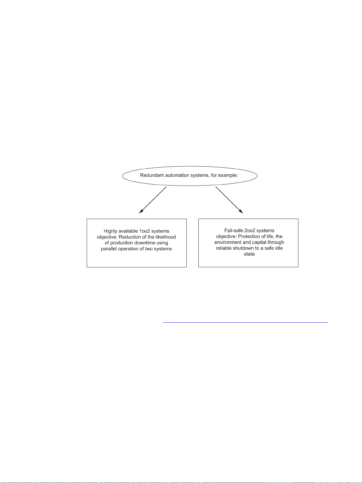
2
2.1
Area of application of the CPU 410 in SIMATIC PCS 7
Purpose of redundant automation systems
Why use fault-tolerant automation systems?
In practice, redundant automation systems are used to achieve fault-tolerant or fail-safe
systems.
Figure 2-1 Purpose of redundant automation systems
Please note the difference between fail-tolerant and fail-safe
systems. The AS 410 H is a fault-tolerance automation system. You may only use it for
controlling safety-related processes if you program and configure it in accordance with the
rules for F systems. You can find information on this in following manual: SIMATIC Industrial
Software S7 F/FH Systems (http://support.automation.siemens.com/WW/view/en/2201072)
The purpose of fault-tolerance automation systems is to reduce production downtime caused
by faults or by maintenance work.
The greater the costs of downtime, the more worthwhile a fault-tolerant system. The costs of
investing in a fault-tolerant system are generally higher, but are rapidly recovered by the
avoidance of production downtime.
CPU 410 Process Automation/CPU 410 SMART
System Manual, 05/2017, A5E31622160-AC
23
Page 24

Introduction to the CPU 410
SIMATIC PCS 7 and CPU 410-5H Process Automation
The SIMATIC PCS 7 project
SIMATIC PCS 7 applications
2.1 Area of application of the CPU 410 in SIMATIC PCS 7
SIMATIC PCS 7 uses selected standard hardware and software components from the TIA
building block system for the process control system in the company-wide automation
network called Totally Integrated Automation. It offers an open basis for automation solutions
with its consistent data management, communication and configuration.
You can use SIMATIC PCS 7 to create customized and project-specific solutions tailored to
specific requirements. Further information about these customized solutions can be found in
the configuration manuals.
The CPU 410-5H Process Automation is a controller of the latest generation. This controller
is specifically designed for the SIMATIC PCS 7 control system. As with previous controllers
of the SIMATIC PCS 7 system, the CPU 410-5H Process Automation can be used in all
Process Automation industries. Highly flexible scalability based on SIMATIC PCS 7 process
objects makes it possible to cover the entire performance range from the smallest to the
largest controller in standard, fault-tolerant and fail-safe applications with just one hardware.
You must create a new configuration for use of a CPU 410-5H. The parameters of a CPU
410-5H are set to SIMATIC PCS 7 default values when a new configuration is created. Some
parameters that were previously freely assignable cannot be changed in the CPU 410-5H.
You can apply charts from existing SIMATIC PCS 7 projects.
A SIMATIC PCS 7 project includes the following objects:
● Hardware configuration
● Blocks
● CFCs and SFCs
These objects are always present - regardless of the number of operator stations and
modules and their networking.
You create a SIMATIC PCS 7 project on an engineering station (ES for short). A variety of
applications are available on the ES:
● SIMATIC Manager - the central application of SIMATIC PCS 7. From here, you can open
all other applications in which you need to make settings for the SIMATIC PCS 7 project.
You will set up your entire project from SIMATIC Manager.
● HW Config – configuration of all hardware of a system, e.g., CPUs, power supply,
communications processors.
● CFC editor and SFC editor - creation of continuous function charts (CFC) and sequential
control systems.
● SIMATIC PCS 7 OS in conjunction with various editors - Implementation of OS
configuration
Every application has a graphic user interface for easy operation and clear representation of
your configuration data.
CPU 410 Process Automation/CPU 410 SMART
24 System Manual, 05/2017, A5E31622160-AC
Page 25
Introduction to the CPU 410
Important information on configuration
WARNING
Open equipment
Additional information
See also
2.2
Possible applications
Important information on configuration
WARNING
Open equipment
2.2 Possible applications
Risk of death or serious injury.
S7–400 modules are classified as open equipment, meaning you must install the S7–400 in
an enclosure, cabinet, or switch room that can only be accessed by means of a key or tool.
Only instructed or authorized personnel are permitted to access these enclosures, cabinets,
or switch rooms.
The components of the standard S7-400 system, e.g., power supplies, I/O modules, CPs,
and FMs, are also used in the high availability S7-400H automation system. For a detailed
description of all hardware components for S7-400, refer to Reference Manual
Automation System, Module Data
.
S7-400
For the S7-400H high availability automation system, the same rules apply for planning the
user program and for using blocks as for a standard S7-400 system. Please observe the
descriptions in the
Programming with STEP 7
300/400 System and Standard Functions
Summary of parameters for CPU 410 (Page 48)
S7–400 modules are classified as open equipment, meaning you must install the S7–400 in
an enclosure, cabinet, or switch room that can only be accessed by means of a key or tool.
Only instructed or authorized personnel are permitted to access these enclosures, cabinets,
or switch rooms.
manual and the
reference manual.
System Software for S7-
CPU 410 Process Automation/CPU 410 SMART
System Manual, 05/2017, A5E31622160-AC
The following figure shows an example of an S7–400H configuration with shared distributed
I/O and connection to a redundant plant bus. The next pages deal with the hardware and
software components required for the installation and operation of the S7–400H.
25
Page 26
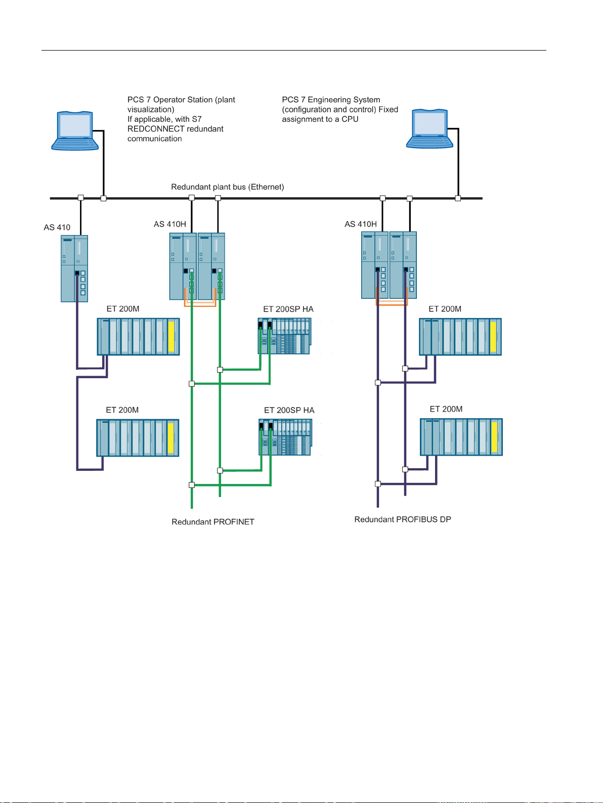
Introduction to the CPU 410
Additional information
2.2 Possible applications
Figure 2-2 Overview
The components of the S7–400 standard system are also used in connection with the CPU
410-5H Process Automation. For a detailed description of all hardware components for S7400, refer to Reference Manual
CPU 410 Process Automation/CPU 410 SMART
S7-400 Automation System; Module Specifications
26 System Manual, 05/2017, A5E31622160-AC
.
Page 27
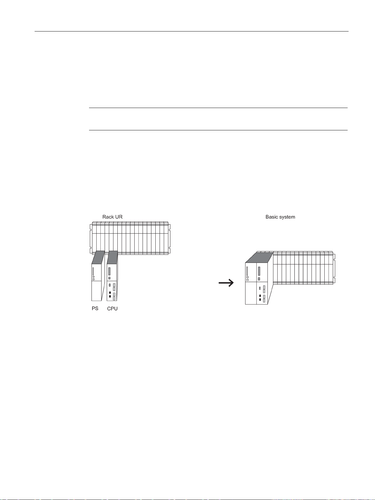
Introduction to the CPU 410
2.3
The CPU 410 basic system for stand-alone operation
Definition
Note
Rack number "0" must be set on the CPU.
Hardware of the basic system
Central controller and expansion units
Power supply
2.3 The CPU 410 basic system for stand-alone operation
Stand-alone operation refers to the use of a CPU 410 in a standard SIMATIC-400 station.
The basic system consists of the required hardware components of a controller. The
following figure shows the components in the configuration.
You can expand the basic system with standard S7-400 modules. There are limitations in the
case of function and communication modules. See Appendix Function and communication
modules that can be used in a redundant configuration (Page 389).
Figure 2-3 Hardware of the S7-400H basic system
The rack containing the CPU is called the central controller (CC). The racks in the system
that are equipped with modules and connected to the CC are the expansion units (EU).
For the power supply you need a power supply module from the standard S7-400 system
spectrum.
To increase availability of the power supply, you can also use two redundant power supplies.
In this case, you use the power supply modules PS 405 R / PS 407 R.
A combination of these can also be used in redundant configurations (PS 405 R with PS 407
R).
CPU 410 Process Automation/CPU 410 SMART
System Manual, 05/2017, A5E31622160-AC
27
Page 28
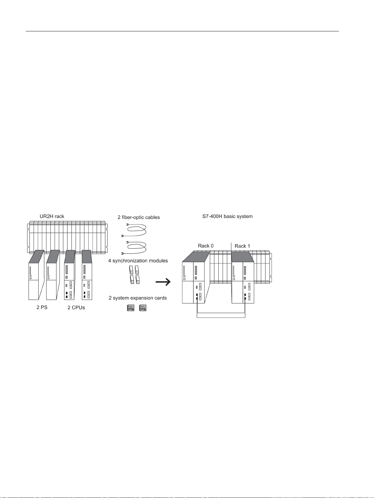
Introduction to the CPU 410
Operation
2.4
The basic system for redundant operation
Hardware of the basic system
Central processing units
on the rear
Rack for S7-400H
2.4 The basic system for redundant operation
You need a system expansion card for operation of a CPU 410. The system expansion card
specifies the maximum number of process objects that can be loaded to the CPU and saves
the license information in case of a system expansion. The system expansion card forms a
hardware unit with the CPU 410.
The basic system consists of the hardware components required for a fault-tolerant
controller. The following figure shows the components in the configuration.
The basic system can be expanded with standard modules of the S7-400. There are
restrictions for the function modules and communication processors. See Appendix Function
and communication modules that can be used in a redundant configuration (Page 389).
Figure 2-4 Hardware of the S7-400H basic system
The two CPUs are the heart of the S7-400H. Use the switch
the rack numbers. In the following sections, we will refer to the CPU in rack 0 as CPU 0, and
to the CPU in rack 1 as CPU 1.
of the CPU to set
The UR2-H rack supports the installation of two separate subsystems with nine slots each,
and is suitable for installation in 19" cabinets.
You can also set up the S7-400H in two separate racks. The racks UR1, UR2, and CR3 are
available for this purpose.
CPU 410 Process Automation/CPU 410 SMART
28 System Manual, 05/2017, A5E31622160-AC
Page 29

Introduction to the CPU 410
Power supply
Synchronization modules
Fiber-optic cable
Operation
2.4 The basic system for redundant operation
You require a power supply module from the standard system range of the S7-400 for each
of the two subsystems of the S7-400H.
To increase availability of the power supply, you can also use two redundant power supplies
in each subsystem. In this case, you use the power supply modules PS 405 R / PS 407 R.
A combination (PS 405 R with PS 407 R) can also be used.
The synchronization modules are used to link the two CPUs. They are installed in the CPUs
and interconnected by means of fiber-optic cables.
Two types of synchronization modules are available:
● Synchronization modules for synchronization cables up to 10 meters long
● Synchronization modules for synchronization cables up to 10 kilometers long
You must use 4 synchronization modules of the same type in a fault-tolerant system. For a
description of the synchronization modules, refer to the section Synchronization modules for
the CPU 410. (Page 239).
The fiber-optic cables are used to interconnect the synchronization modules for the
redundant link between the two CPUs. They interconnect the upper and lower
synchronization modules in pairs.
You will find the specification of the fiber-optic cables you can use in an S7-400H in the
section Selecting fiber-optic cables (Page 245).
You need a system expansion card for operation of a CPU 410. The system expansion card
specifies the maximum number of process objects that can be loaded to the CPU and saves
the license information in case of a system expansion. The system expansion card forms a
hardware unit with the CPU 410. In redundant operation, each CPU 410 must have a system
expansion card with identical quantity framework and scope of functions.
CPU 410 Process Automation/CPU 410 SMART
System Manual, 05/2017, A5E31622160-AC
29
Page 30

Introduction to the CPU 410
2.5
Rules for H station assembly
2.6
I/O for the CPU 410
2.5 Rules for H station assembly
The following rules have to be complied with for a fault-tolerant station, in addition to the
rules that generally apply to the arrangement of modules in the S7-400:
● The CPUs have to be inserted in the same slots.
● Redundantly used external CP443-5DX DP master interfaces or communication modules
must be inserted in the same slots in each case.
● External DP master interface modules for redundant DP master systems may only be
inserted in central controllers and not in expansion units.
● Redundantly used CPUs must be identical, which means they must have the same article
number, product version and firmware version. It is not the marking on the front side that
is decisive for the product version, but the revision of the "Hardware" component
("Module status" dialog mask) to be read using STEP 7.
● Redundantly used other modules must be identical, i.e. they must have the same article
number, product version and - if available - firmware version.
● Two CPU 410-5H must have system expansion cards with the same configuration size
and the same functional scope.
You can use SIMATIC S7 input/output modules with the CPU 410. The I/O modules can be
used in the following devices:
● Central controllers
● Expansion units
● Distributed via PROFIBUS DP
● Distributed via PROFINET IO
The function modules (FM) and communication modules (CP) that can be used with CPU
410 are listed in the appendix Function and communication modules that can be used in a
redundant configuration (Page 389).
CPU 410 Process Automation/CPU 410 SMART
30 System Manual, 05/2017, A5E31622160-AC
Page 31

Introduction to the CPU 410
2.7
I/O configuration variants of the fault-tolerant system
I/O configuration variants
2.8
Configuration tools (STEP 7 HW Config, SIMATIC PCS 7)
Optional software
2.9
The SIMATIC PCS 7 project
STEP 7
2.7 I/O configuration variants of the fault-tolerant system
The following configuration variants are available for the input/output modules:
● In stand-alone operation: one-sided configuration.
In the one-sided configuration, there is a single set of the input/output modules (singlechannel) that are addressed by the CPU.
● In redundant operation: Single-channel switched configuration with enhanced availability.
In the single-channel switched distributed configuration, there is a single set of the I/O
modules, but they can be addressed by both subsystems.
● In redundant operation: Dual-channel configuration with maximum availability.
In dual-channel switched configuration, there are two of each of the input/output modules
and the modules can be addressed by both subsystems.
Like S7-400, CPU 410-5H Process Automation is configured with STEP 7 HW Config.
You can find information on limitations for configuring CPUs and the fault-tolerant system in
the STEP 7 HW Config online help.
You can use all optional packages available in SIMATIC PCS 7.
STEP 7 is the core component for configuring the SIMATIC PCS 7 process control system
with the engineering system.
STEP 7 supports the various tasks involved in creating a project with the following project
views:
● Component view (HW Config)
● Process object view
● Technological perspective
The hardware that you need in a SIMATIC project, such as automation systems,
communication components, and process I/O, is stored in an electronic catalog. You
configure this hardware and assign the hardware parameters with HW Config.
CPU 410 Process Automation/CPU 410 SMART
System Manual, 05/2017, A5E31622160-AC
31
Page 32

Introduction to the CPU 410
2.9.1
Scaling and licensing (scaling concept)
License management
Use of the system expansion card
Expansion of a PCS 7 project
Expanding the number of POs by replacing the SEC
2.9 The SIMATIC PCS 7 project
You can protect function blocks (FBs) and functions (FCs) against unauthorized access
using the S7 Block Privacy application. You can no longer edit protected blocks in STEP 7.
Only the interfaces of the blocks are then visible.
If you protect blocks with S7 Block Privacy, you may encounter longer download and startup
times.
License objects are process objects (PO) and their associated runtime licenses (RT-PO).
When a SIMATIC PCS 7 application is created, the SIMATIC PCS 7 system determines the
number of POs that corresponds to the scope of that application.
For productive operation of the SIMATIC PCS 7 application, there must be enough runtime
licenses (AS RT POs) to cover the required number of POs. The system expansion card of
the associated CPU 410-5H must also have at least the same PO count.
The CPU is scaled by means of the system expansion card, which means the system
expansion card determines the maximum quantity of POs. The CFC counts and manages
the POs used in the application. The number of POs that can be downloaded to the CPU is
limited to the maximum number of POs specified by the system expansion card.
The number of POs of a CPU 410 is stored on a system expansion card (SEC). You insert
the SEC in a slot on the back of the CPU before commissioning the CPU. The SEC is an
essential part of the CPU hardware. The CPU cannot be operated without an SEC. If no
valid SEC is detected, the corresponding CPU does not start up. A loss of synchronization is
triggered in the fault-tolerant system, in which a start-up block prevents automatic
reconnection. You cannot operate two CPUs 410 redundantly with two different SECs.
When you expand a SIMATIC PCS 7 project and load it to the CPU, the system checks
whether the project can run in the CPU with the current number of POs. If this is not the
case, you have two options to expand the number of POs:
● Replacing the system expansion card
● Online with CPU 410 expansion packs.
There are expansion packs with 100 POs and with 500 POs. These can also be
combined.
To replace the system expansion card (SEC), you must remove the CPU. You must replace
both SECs for redundant operation. The new SECs must have the same number of POs.
CPU 410 Process Automation/CPU 410 SMART
32 System Manual, 05/2017, A5E31622160-AC
Page 33

Introduction to the CPU 410
Expanding the number of POs without replacing the SEC
Note
This function can
expand
number of POs without replacing the SEC.
Expansion of the functionality of the CPU
2.9 The SIMATIC PCS 7 project
You can expand the number of POs in four steps without replacing the SEC.
Step 1: Order the number CPU 410 expansion packs you need using the regular ordering
process. You can order expansions for 100 POs and 500 POs.
Step 2: Assign the CPU 410 expansion packs to the respective CPU.
Step 3: Activate the expansion.
Step 4: Transfer the release of the expansion to the CPU.
A detailed description of the procedure is available in the
Service support and diagnostics (V8.1)
only be used to
You can activate support for redundant subsystems for the CPU:
● Step 1: Follow the standard ordering procedure to obtain the necessary license.
● Step 2: Assign the license to the relevant CPU.
● Step 3: Activate the expansion.
● Step 4: Transfer the activation of the expansion to the CPU.
PCS 7 process control system,
manual.
the number of POs. You cannot the reduce the
CPU 410 Process Automation/CPU 410 SMART
System Manual, 05/2017, A5E31622160-AC
33
Page 34

Introduction to the CPU 410
2.9 The SIMATIC PCS 7 project
CPU 410 Process Automation/CPU 410 SMART
34 System Manual, 05/2017, A5E31622160-AC
Page 35
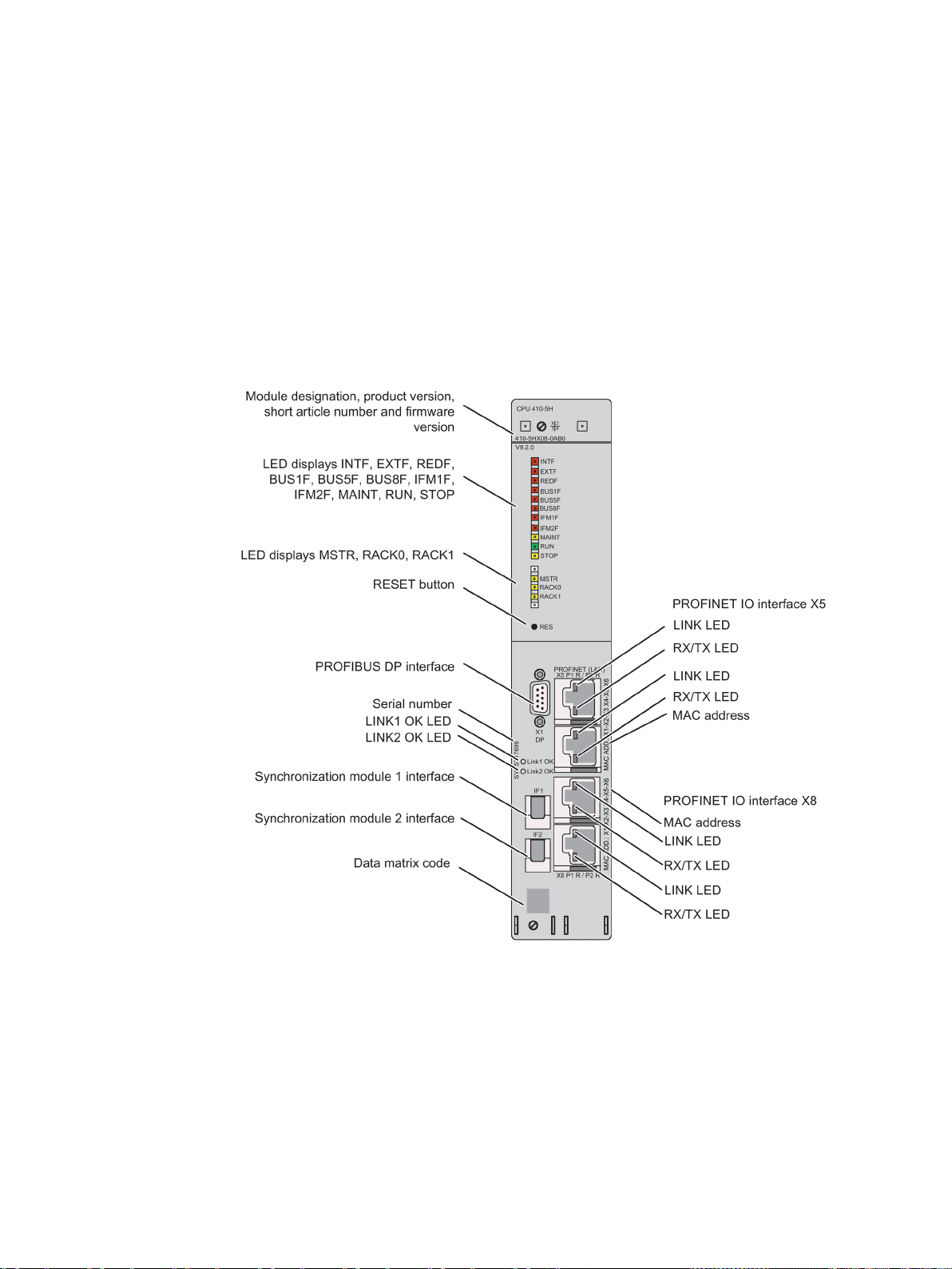
3
3.1
Operator controls and indicators on the CPU 410
Arrangement of the operator controls and indicators on the CPU 410
Figure 3-1 Arrangement of the operator controls and indicators on the CPU 410
CPU 410 Process Automation/CPU 410 SMART
System Manual, 05/2017, A5E31622160-AC
35
Page 36

Configuration of the CPU 410
LED displays
LED display
Color
Meaning
Top bar
EXTF
red
External error
REDF
red
Loss of redundancy/Redundancy fault
BUS1F
red
Bus fault at the PROFIBUS interface
BUS5F
red
Bus fault at the first PROFINET IO interface
BUS8F
red
Bus fault at the second PROFINET IO interface
IFM1F
red
Error in synchronization module 1
IFM2F
red
Error in synchronization module 2
MAINT
yellow
Maintenance request pending
RUN
green
RUN mode
STOP
yellow
STOP mode
Bottom bar
MSTR
yellow
CPU controls the process
RACK0
yellow
CPU in rack 0
RACK1
yellow
CPU in rack 1
For the interfaces
LINK
green
Connection at the PROFINET IO interface is active
RX/TX
orange
Receiving or sending data at the PROFINET IO interface.
LINK 1 OK
green
Connection via synchronization module 1 is active and OK
Reset button
Slot for synchronization modules
3.1 Operator controls and indicators on the CPU 410
The following table gives an overview of the available LED displays.
Sections CPU 410 monitoring functions (Page 39) and Status and error displays
(Page 41) describe the states and errors/faults indicated by these LEDs.
Table 3- 1 LED displays on the CPUs
INTF red Internal error
LINK 2 OK green Connection via synchronization module 2 is active and OK
You operate the reset button in the following cases:
● You want to reset the CPU to the factory state, see section Resetting the CPU 410 to
delivery condition (reset to factory setting) (Page 142)
● You want to reset the CPU during operation, see section Reset during operation
(Page 143)
The reset button is on the front of the CPU directly below the LED strip. Press it with a
suitably thin round object.
The synchronization modules for redundant operation are inserted in these slots. See
section Synchronization modules (Page 239).
CPU 410 Process Automation/CPU 410 SMART
36 System Manual, 05/2017, A5E31622160-AC
Page 37

Configuration of the CPU 410
PROFIBUS DP interface
PROFINET IO interface
Label
Meaning
X5 P1 R
Interface X5, Port 1, ring port possible
X8 P1 R
Interface X8, Port 1, ring port possible
X8 P2 R
Interface X8, Port 2, ring port possible
When media redundancy is activated, the corresponding port is configured as a ring port.
NOTICE
Connecting only to Ethernet LAN
3.1 Operator controls and indicators on the CPU 410
You can connect the distributed I/O to the PROFIBUS DP interface.
The PROFINET IO interfaces establish the connection to Industrial Ethernet. The
PROFINET IO interfaces also serve as the access point for the engineering system. The
PROFINET IO interfaces feature two switched ports with external connectors (RJ 45). You
can find further information on PROFINET IO in sections PROFINET IO systems (Page 52).
The meaning of the interface labels is as follows:
X5 P2 R Interface X5, Port 2, ring port possible
These interfaces only allow connection to an Ethernet LAN. You cannot connect them to
the public telecommunication network, for example.
You may only connect PROFINET IO-compliant network components to this interface.
CPU 410 Process Automation/CPU 410 SMART
System Manual, 05/2017, A5E31622160-AC
37
Page 38
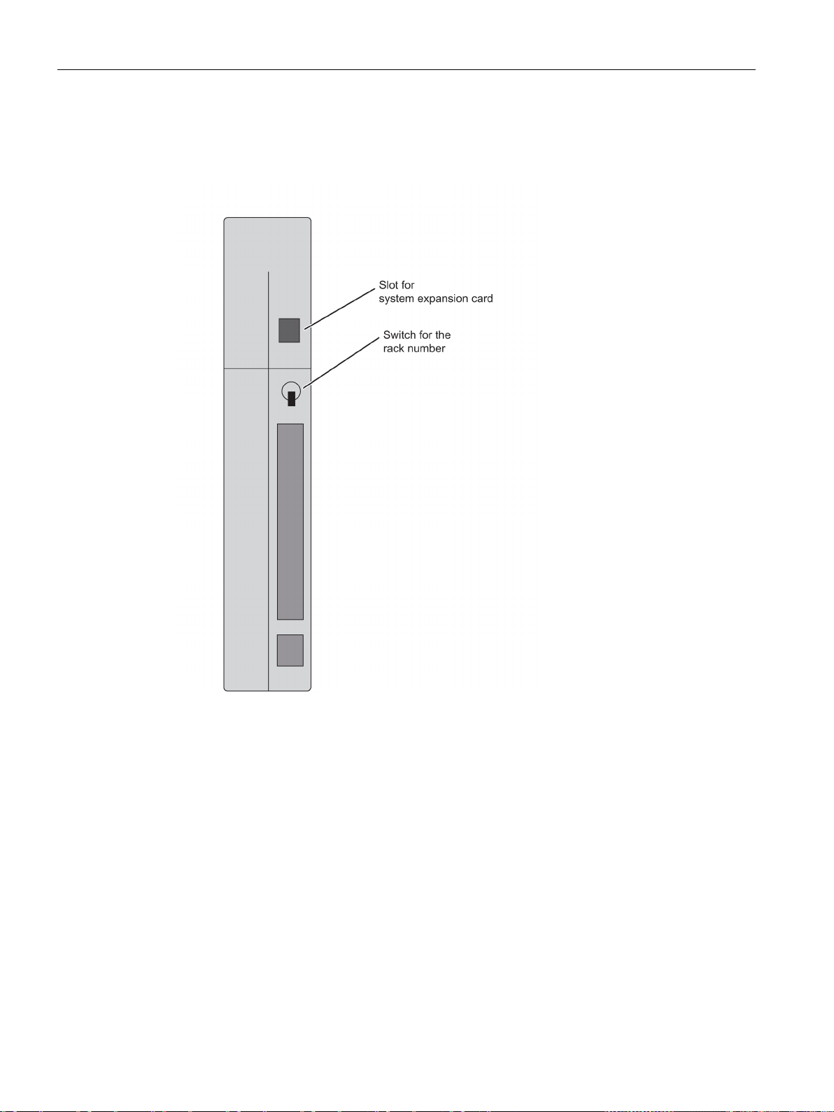
Configuration of the CPU 410
Rear of the CPU 410
Setting the rack number
Slot for system expansion card
3.1 Operator controls and indicators on the CPU 410
Use the switch on the rear panel of the CPU to set the rack number. The switch has two
positions: 1 (up) and 0 (down). One CPU is allocated rack number 0, and the partner CPU is
assigned rack number 1. The default setting of all CPUs is rack number 0.
The back of the CPU has a slot in which you insert the system expansion card (SEC) before
commissioning the CPU. The SEC contains information that specifies the performance class
of the CPU in terms of the amount of POs it supports. The SEC is an essential part of the
CPU hardware. The CPU cannot be operated without an SEC. If an SEC is not detected, the
corresponding CPU goes to STOP and requests a memory reset. "STOP by CPU memory
management" is also entered in the diagnostics buffer.
You need a small screwdriver to remove the SEC. Place the screwdriver at the top of the
SEC slot and lift out the SEC with the screwdriver.
CPU 410 Process Automation/CPU 410 SMART
38 System Manual, 05/2017, A5E31622160-AC
Page 39

Configuration of the CPU 410
3.2
CPU 410 monitoring functions
Monitoring functions and error messages
Type of error
Cause of error
Error LED
Access error
Module failure (SM, FM, CP)
EXTF
and goes out with the outgoing diagnostic interrupt.
Removing a synchronization module.
3.2 CPU 410 monitoring functions
The hardware of the CPU and operating system provide monitoring functions to ensure
proper operation and defined reactions to errors. Various errors may also trigger a reaction
in the user program.
The table below provides an overview of possible errors and their causes, and the
corresponding responses of the CPU.
Additional test and information functions are available in each CPU; they can be initiated in
STEP 7.
Time error
Power supply module(s)
fault (not power failure)
Diagnostic interrupt An I/O module with interrupt capability reports a diagnostic interrupt
Swapping interrupt Removing or inserting a module as well as inserting an incorrect
Redundancy error
CPU hardware fault
Program execution error
• The user program execution time (OB 1 and all interrupts and
error OBs) exceeds the specified maximum cycle time.
• OB request error
• Overflow of the start information buffer
• Time-of-day error interrupt
In the central or S7-400 expansion rack
• at least one backup battery of the power supply module is com-
pletely discharged.
• the backup battery voltage is missing.
• the 24 V supply to the power supply module has failed.
The synchronization module signals a diagnostic interrupt; see
Chapter Synchronization modules for the CPU 410. (Page 239)
The LED EXTF lights up with the first incoming diagnostic interrupt
module type.
• Loss of redundancy on the CPUs
• Redundancy loss/ station failure of a switched DP station
• Failure of a DP master
• Redundancy loss/station failure of a switched IO device
• A memory error was detected and eliminated
• Priority class is called, but the corresponding OB is not availa-
ble.
• In the event of an SFB call: Missing or faulty instance DB
• Process image update error
INTF
EXTF
EXTF
EXTF
REDF
INTF
INTF
EXTF
CPU 410 Process Automation/CPU 410 SMART
System Manual, 05/2017, A5E31622160-AC
39
Page 40

Configuration of the CPU 410
Type of error
Cause of error
Error LED
brary.
software
error).
brary.
compiled user program, for example, illegal OP code or
brary.
3.2 CPU 410 monitoring functions
Failure of a rack/station
Communication error Communication error:
Execution canceled The execution of a program block was canceled. Possible reasons
Missing license for Runtime
Programming error User program error:
• Power failure in an S7-400 expansion unit
• Failure of a DP/PN segment
• Failure of a coupling segment: Missing or defective IM, inter-
rupted cable
• Time synchronization
• Access to DB when exchanging data via communications func-
tion blocks
for the cancellation are:
• Nesting depth of nesting levels too great
• Nesting depth of master control relay too great
• Nesting depth of synchronization errors too great
• Nesting depth of block call commands (U stack) too great
• Nesting depth of block call commands (B stack) too great
• Error during allocation of local data
Such errors cannot occur with blocks from a SIMATIC PCS 7 li-
The Runtime software could not be completely licensed (internal
• BCD conversion error
• Range length error
• Range error
• Alignment error
• Write error
• Timer number error
• Counter number error
• Block number error
• Block not loaded
Such errors cannot occur with blocks from a SIMATIC PCS 7 li-
EXTF
BUSF for PN and DP
REDF for redundant
segments
INTF
INTF
INTF
INTF
MC7 code error Error in the
CPU 410 Process Automation/CPU 410 SMART
40 System Manual, 05/2017, A5E31622160-AC
INTF
a jump beyond the block end
Such errors cannot occur with blocks from a SIMATIC PCS 7 li-
Page 41

Configuration of the CPU 410
3.3
Status and error displays
RUN and STOP LEDs
LED
Meaning
RUN
STOP
possible.
2 Hz
2 Hz
0.5 Hz
RUN, there might be an error in the system configuration, for example.
0.5 Hz
access to the CPU until completed.
the load memory, set the CPU to delivery state before powering it up.
3.3 Status and error displays
The RUN and STOP LEDs provide information about the CPU's currently active operating
state.
Table 3- 2 Possible states of the RUN and STOP LEDs
Lit Dark CPU is in RUN state.
Dark Lit CPU is in STOP state. The user program is not being executed. Cold restart/restart is
Flashes
Flashes
Flashes
2 Hz
Dark Flashes
Dark Flashes
Flashes
0.5 Hz
Flashes
0.5 Hz
Flashes
Lit HOLD status has been triggered by a test function.
Lit A cold restart/restart was initiated. The cold restart/warm start may take a minute or
2 Hz
Flashes
0.5 Hz
Flashes
2 Hz
The CPU has detected a serious error that is blocking startup. All other LEDs also
flash at 2 Hz.
longer, depending on the length of the called OB. If the CPU still does not change to
• A high-quality RAM test (self-test) is executed after POWER ON. The duration of
the self-test is at least 7 minutes.
• CPU memory reset is active.
The CPU requests a memory reset.
• Troubleshooting mode
• Startup (POWER ON) of a CPU on which a large number of blocks is loaded. If
encrypted blocks are loaded, startup may take a longer time depending on the
number of such blocks.
This display also indicates that internal processes are busy on the CPU and prevent
The CPU has downloaded another program and is powering up after power on.
Note that, if necessary, another program and a configuration may be present in the
retentive load memory in the CPU. Ensure that this cannot pose a hazard if the CPU
switches automatically to RUN state. If you have no information about the content of
CPU 410 Process Automation/CPU 410 SMART
System Manual, 05/2017, A5E31622160-AC
41
Page 42

Configuration of the CPU 410
MSTR, RACK0, and RACK1 LEDs
LED
Meaning
MSTR
RACK0
RACK1
Lit
Irrelevant
Irrelevant
CPU controls switched I/O
Irrelevant
Lit
Dark
CPU on rack number 0
INTF and EXTF LEDs
LED
Meaning
INTF
EXTF
error).
Irrelevant
Lit
An external error has been detected (i.e. an error not caused by the CPU)
BUS1F, BUS5F, and BUS8F LEDs
LED
Meaning
BUS1F
BUS5F
BUS8F
Lit
Irrelevant
Irrelevant
An error was detected on the PROFIBUS DP interface X1.
A PROFINET IO system is configured but not connected.
A PROFINET IO system is configured but not connected.
Irrelevant
Flashes
Irrelevant
One or more devices on the first PROFINET IO interface X5 is not responding.
Irrelevant
Irrelevant
Flashes
One or more devices on the second PROFINET IO interface X8 is not responding.
Flashes
Irrelevant
Irrelevant
One or more slaves on the PROFIBUS DP interface X1 is not responding.
3.3 Status and error displays
The three LEDs MSTR, RACK0, and RACK1 provide information about the rack number set
on the CPU and show which CPU controls the switched I/O.
Table 3- 3 Possible states of the MSTR, RACK0 and RACK1 LEDs
Irrelevant Dark Lit CPU on rack number 1
The two INTF and EXTF LEDs provide information about errors and other particular things
that happen during user program execution.
Table 3- 4 Possible states of the INTF and EXTF LEDs
Lit Irrelevant An internal error was detected (programming, parameter assignment, or license
The BUS1F, BUS5F and BUS8F LEDs indicate errors associated with the PROFIBUS DP
interface and the PROFINET IO interfaces.
Table 3- 5 Possible states of the BUS1F, BUS5F, and BUS8F LEDs
Irrelevant Lit Irrelevant An error was detected on the first PROFINET IO interface X5.
Irrelevant Irrelevant Lit An error was detected on the second PROFINET IO interface X8.
CPU 410 Process Automation/CPU 410 SMART
42 System Manual, 05/2017, A5E31622160-AC
Page 43

Configuration of the CPU 410
IFM1F and IFM2F LEDs
LED
Meaning
IFM1F
IFM2F
Irrelevant
Lit
An error was detected on synchronization module 2
LINK and RX/TX LEDs
LED
Meaning
LINK
RX/TX
Lit
Irrelevant
Connection at the PROFINET IO interface is active
Note
The LINK and RX/TX LEDs are located directly next to the sock
interfaces. They are not labeled.
REDF LED
REDF LED
System state
Basic requirements
0.5 Hz
2 Hz
3.3 Status and error displays
The IFM1F and IFM2F LEDs indicate errors on the first or second synchronization module.
Table 3- 6 Possible states of the IFM1F and IFM2F LEDs
Lit Irrelevant An error was detected on synchronization module 1.
The LINK and RX/TX LEDs indicate the current state of the PROFINET IO interfaces.
Table 3- 7 Possible states of the LINK and RX/TX LEDs
Irrelevant Flashes
6 Hz
Receiving or sending data at the PROFINET IO interface.
The REDF LED indicates specific system states and redundancy errors.
Table 3- 8 Possible states of the REDF LED
Flashes
Flashes
Link-up -
Update -
ets of the PROFINET IO
CPU 410 Process Automation/CPU 410 SMART
System Manual, 05/2017, A5E31622160-AC
43
Page 44

Configuration of the CPU 410
REDF LED
System state
Basic requirements
Dark
Redundant (CPUs are redundant)
No redundancy error
LEDs LINK1 OK and LINK2 OK
LED LINKx OK
Meaning
Lit
The connection is OK
Check whether the synchronization module works in another CPU.
If necessary, replace the synchronization module in the other CPU.
LED MAINT
Diagnostics buffer
3.3 Status and error displays
Lit Redundant (CPUs are redundant) There is an I/O redundancy error:
• Failure of a DP master, or partial or total failure of a
DP master system
• Failure of a PN IO subsystem
• Loss of redundancy on the DP slave
• Loss of redundancy at the PN IO device
• Loss of redundancy on the DP slave/slave failure
• Loss of redundancy at the PN IO device/device
failure
When commissioning the fault-tolerant system, you can use the LINK1 OK and LINK2 OK
LEDs to check the quality of the connection between the CPUs.
Table 3- 9 Possible states of the LINK1 OK and LINK2 OK LEDs
Flashes The connection is not reliable, and the signal is disrupted
Check the connectors and cables
Ensure that the fiber-optic cables are installed in accordance with the guidelines in Chapter
Installation of fiber-optic cables (Page 243).
Dark The connection is interrupted, or there is insufficient light intensity
Check the connectors and cables
Ensure that the fiber-optic cables are installed in accordance with the guidelines in Chapter
Installation of fiber-optic cables (Page 243).
Check whether the synchronization module works in another CPU.
This LED indicates that maintenance is required. Maintenance is required when there are
problems with the synchronization modules or if maintenance is demanded by one of the
PROFINET devices. For more information, refer to the STEP 7 Online Help.
The LED MAINT also displays an error during address assignment of the PROFINET
interfaces X5 or X8.
In STEP 7, you can select "PLC -> Module Information" to read the cause of an error from
the diagnostics buffer.
CPU 410 Process Automation/CPU 410 SMART
44 System Manual, 05/2017, A5E31622160-AC
Page 45

Configuration of the CPU 410
3.4
PROFIBUS DP interface (X1)
Connectable devices
Connectors
Redundant operation
3.5
PROFINET IO interfaces (X5, X8)
Assigning an IP address
Devices that can be connected via PROFINET IO (PN)
3.4 PROFIBUS DP interface (X1)
The PROFIBUS DP interface can be used to set up a PROFIBUS master system, or to
connect PROFIBUS I/O devices.
All DP slaves that conform to the standard can be connected to the PROFIBUS DP interface.
You can connect the PROFIBUS DP I/O to the PROFIBUS DP interface in redundant or
single-channel switched configuration.
In this case, the CPU is the DP master, which is connected to the passive slave stations or,
in stand-alone operation, to other DP masters.
Some of the devices that can be connected draw 24 V from the interface for their power
supply. This voltage is provided as non-isolated voltage at the PROFIBUS DP interface.
Use only PROFIBUS DP bus connectors or PROFIBUS cables for connecting devices to the
PROFIBUS DP interface (
see installation manual
).
The PROFIBUS DP interfaces have the same baud rate and the same operating mode in
redundant operation.
You assign an IP address to an Ethernet interface in the CPU properties using HW Config.
Download the modified configuration to the CPU. The IP address is valid for the duration of
the project.
For technical reasons, the two interfaces X5/X8 must be located in different IP subnets.
● SIMATIC PCS 7 ES/OS with Ethernet network card or CP16xx communications
processor
● Active network components, e.g., Scalance X200
● S7-300/S7-400, e.g., CPU 417-5H or communication processor CP443-1
● PROFINET IO devices, e.g. ET 200SP HA or ET 200M
CPU 410 Process Automation/CPU 410 SMART
System Manual, 05/2017, A5E31622160-AC
45
Page 46

Configuration of the CPU 410
Connectors
Properties of the PROFINET IO interfaces
Protocols and communication functions
PROFINET IO
PG functions
Yes
Detection of the network topology (LLDP)
Yes
Media redundancy (MRP)
Yes
Time synchronization in NTP method as client
Yes
Time synchronization in SIMATIC method
Yes
Time synchronization in pTCP method
Yes
Connection per interface
Version
2 x RJ45
Switch with 2 ports
Media
Twisted pair Cat5
Transmission rate
10/100 Mbps
Autonegotiation
3.5 PROFINET IO interfaces (X5, X8)
The PROFINET interfaces are implemented as Ethernet RJ45 interfaces. Always use RJ45
connectors to hook up devices to a PROFINET interface.
According to IEC 61784-2 Conformance Class A und B
Open block communication over
S7 communication Yes
Port statistics of PN IO devices (SNMP) Yes
• TCP
• UDP
• ISO-on-TCP
You can find further information about the properties of the PROFINET IO interfaces in the
technical specifications of the CPUs in section Technical data (Page 253).
Autosensing
Autocrossing
CPU 410 Process Automation/CPU 410 SMART
46 System Manual, 05/2017, A5E31622160-AC
Page 47

Configuration of the CPU 410
Note
Networking of PROFINET IO components
The PROFINET IO interfaces of our devices are set to "automatic setting" (autonegotiation)
by default. Verify that all devices connected to the PROFINET IO interface of the CPU are
also set to the "Autonegot
IO/Ethernet components.
If you connect a device to a PROFINET IO interface of the CPU that does not support the
"automatic setting" (Autonegotiation) operating mode or you choose a setting othe
"automatic setting" (Autonegotiation) for this device, note the following:
•
•
Background: If a switch that is
interface of the CPU, the "Autonegotiation" setting forces the CPU to adapt itself to the
settings of the partner device, which means the communication operates de facto at
"10
PROFINET IO demands operation at 100
option to address IO devices.
Reference
3.5 PROFINET IO interfaces (X5, X8)
iation" mode. This is the default setting of standard PROFINET
r than the
PROFINET IO requires 100 Mbps full-duplex operation, which means if the PROFINET
IO interface of the CPU is used simultaneously for PROFINET IO communication and
Ethernet communication, operation of the PROFINET IO interface is permissible only in
100 Mbps full-duplex mode.
If an PROFINET IO interface of the CPU is used for Ethernet communication only, 100
Mbps full-duplex mode is possible.
permanently set to "10 Mbps half-duplex" is connected to an
Mbps half-duplex". This is permitted for an Ethernet communication. But because
Mbps full-duplex, this would not be a long-term
● For details about PROFINET, refer to PROFINET System Description
(http://support.automation.siemens.com/WW/view/en/19292127)
● For detailed information about Ethernet networks, network configuration and network
components refer to SIMATIC NET Manual: Twisted-Pair and Fiber-Optic Networks
(http://support.automation.siemens.com/WW/view/en/8763736).
● For additional information about PROFINET IO, refer to: PROFINET
(http://www.profibus.com/)
CPU 410 Process Automation/CPU 410 SMART
System Manual, 05/2017, A5E31622160-AC
47
Page 48

Configuration of the CPU 410
3.6
Summary of parameters for CPU 410
Default values
Parameter blocks
Parameter assignment tool
Further settings
3.6 Summary of parameters for CPU 410
All parameters are set to factory defaults. These defaults are suitable for a wide range of
standard applications and can be used to operate the CPU 410 directly without having to
make any additional settings.
You can define the defaults using the "Configuring Hardware" tool in STEP 7.
The responses and properties of the CPU are defined in parameters. The CPU 410 has a
defined default setting. You can modify this default setting by editing the parameters in the
hardware configuration.
The list below provides an overview of the assignable system properties of the CPUs.
● General properties such as the CPU name
● Watchdog interrupts, e.g., priority, interval duration
● Diagnostics/clock, e.g., time-of-day synchronization
● Security levels
● H parameters, e.g., duration of a test cycle
● Startup, for example, times for completed message from modules and transfer of
parameters to modules
You can set the individual CPU parameters using "Configuring hardware" in STEP 7. For
additional information, see I/O configuration variants (Page 55).
● The rack number of a CPU 410, 0 or 1
Use the selector switch on the rear panel of the CPU to change the rack number.
● The operating mode of a CPU 410, stand-alone operation or redundant operation
You set the operating mode by configuring a SIMATIC 400 station (stand-alone
operation) or a SIMATIC H station in HW Config.
CPU 410 Process Automation/CPU 410 SMART
48 System Manual, 05/2017, A5E31622160-AC
Page 49

4
4.1
CPU 410 as PROFIBUS DP master
Startup of the DP master system
PROFIBUS address of the DP master
Output and input data length
4.2
Diagnostics of the CPU 410 as PROFIBUS DP master
Diagnostics using LED displays
BUS1F
Meaning
Remedy
all configured slaves are addressable
You use the following parameters to set startup monitoring of the DP master:
● Ready message from module
● Transfer of parameters to modules
This means that the DP slaves must be started up and their parameters assigned by the
CPU (as DP master) within the set time.
PROFIBUS addresses 0 to 126 are permissible.
The maximum output or input data length you can use for each DP station is 244 bytes.
When an ET 200PA SMART is used, the maximum usable output or input data length is 242
bytes
For each ET 200PA SMART you are using in a DP line, the total number of user data of this
DP line is reduced by one output word and one input word.
Table 4- 1 Meaning of the "BUSF" LED of the CPU 410 as DP master
Off Configuration correct;
The following table explains the meaning of the BUS1F LED.
-
Lit
CPU 410 Process Automation/CPU 410 SMART
System Manual, 05/2017, A5E31622160-AC
• Bus fault (physical fault) • Check whether the bus cable has shorted.
• DP interface fault
• Different baud rates in multi-DP master
operation (only in stand-alone operation)
• Analyze the diagnostic data. Reconfigure or correct the
configuration.
49
Page 50

PROFIBUS DP
BUS1F
Meaning
Remedy
Diagnostic addresses for the DP master
4.2 Diagnostics of the CPU 410 as PROFIBUS DP master
Flashes
• Station failure
• At least one of the assigned slaves cannot
be addressed
You assign diagnostic addresses for PROFIBUS DP for the CPU 410.
When configuring the DP master, you specify a diagnostic address for the DP slave in the
associated project of the DP master.
This diagnostic address is used by DP master to obtain information about the status of DP
slave or a bus interruption.
• Check whether the bus cable is connected to the
CPU 410 or the bus is interrupted.
• Wait until the CPU 410 has started up. Check the DP
slaves if the LED does not stop flashing. If possible,
evaluate the diagnostics of the DP slaves with direct access via the bus.
CPU 410 Process Automation/CPU 410 SMART
50 System Manual, 05/2017, A5E31622160-AC
Page 51

5
5.1
Introduction
What is PROFINET IO?
RT communication (real-time communication)
Documentation on the Internet
PROFINET IO is the open, cross-vendor Industrial Ethernet standard for automation. It
enables continuous communication from the business management level down to the field
level. PROFINET IO is based on switched Ethernet with full duplex mode and a bandwidth of
100 Mbps.
With PROFINET IO a switching technology is implemented that allows all stations to access
the network at any time. As a result, the network can be utilized more efficiently through
simultaneous data transmission of multiple nodes. Simultaneous sending and receiving is
enabled through the full-duplex operation of Switched Ethernet.
In PROFINET IO communication, a portion of the transmission time is reserved for cyclic,
deterministic data transmission (real-time communication). This allows you to split the
communication cycle into a deterministic and an open part. Communication takes place in
real-time.
RT communication is the basic communication mechanism for PROFINET IO and is used
during device monitoring. The transmission of real-time data with PROFINET IO is based on
the cyclic data exchange with a provider-consumer model. To better scale the
communication options and therefor the determinism for PROFINET IO, real-time classes
have been defined for data exchange. These are unsynchronized and synchronized
communication. The details are handled independently in the field devices. Real-time
automatically includes an increase in priority with PROFINET compared to UDP/IP frames.
This is necessary to prioritize the transmission of data in the switches so that RT frames are
not delayed by UDP/IP frames.
Comprehensive information about PROFINET (http://www.profibus.com/) is available on the
Internet.
Also observe the following documents:
● Installation guideline
● Assembly guideline
● PROFINET_Guideline_Assembly
Additional information on the use of PROFINET IO in automation engineering is available at
the following Internet address (http://www.siemens.com/profinet/).
CPU 410 Process Automation/CPU 410 SMART
System Manual, 05/2017, A5E31622160-AC
51
Page 52
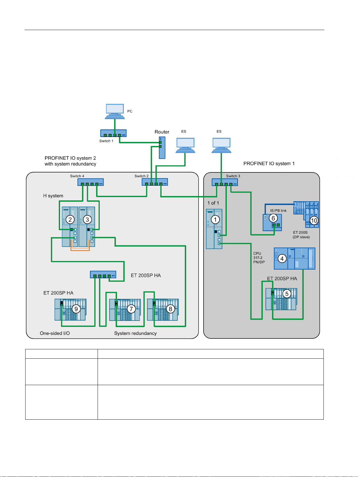
PROFINET IO
5.2
PROFINET IO systems
Functions of PROFINET IO
The graphic shows
Examples of connection paths
can also access one of the other areas of the Industrial Ethernet from an ES on the field
5.2 PROFINET IO systems
The following graphic shows the new functions in PROFINET IO:
The connection of company
network and field level
Connections between the
automation system and field
level
CPU 410 Process Automation/CPU 410 SMART
52 System Manual, 05/2017, A5E31622160-AC
You can access devices at the field level from PCs in your company network
• Example:
PC - Firewall - Switch 1 - Router - Switch 2 - Switch 3 - CPU 410
You
level.
Example:
• ES - Integrated switch 3 - Switch 2 - Switch 4 - CPU 410
①.
③.
Page 53

PROFINET IO
The graphic shows
Examples of connection paths
Further information
5.3
Device replacement without exchangeable medium / ES
5.3 Device replacement without exchangeable medium / ES
The IO controller of CPU
① spans
410
PROFINET IO system 1
and directly controls devices
on the Industrial Ethernet
and PROFIBUS.
The fault-tolerant system,
consisting of CPU 410
② + ③, spans the
PROFINET IO system 2 as
IO controller.
This IO controller operates
IO devices in system redundancy as well as a onesided IO device.
You will find further information about PROFINET IO in the documents listed below:
At this point, you see the IO features between the IO controller, intelligent device, and the
IO device(s) on Industrial Ethernet:
• The CPU 410
– for the ET 200SP HA I/O device
– for switch 3
– for the I device CPU 317-2 PN/DP
– for the IE/PB link ⑥
• The IE/PB link is the master for the DP slave ⑩ and maps the latter as a device ⑩ in
the PROFINET IO.
The fault-tolerant system, consisting of CPU 410 ② + ③, spans the PROFINET IO controller system 2 as IO controller. This IO controller operates IO devices in system redundancy
as well as a one-sided IO device.
Here, you can see that a fault-tolerant system can operate both system-redundant IO devic-
es and one-sided IO devices:
• The fault-tolerant system with its two IO controllers in rack 0 and rack 1 provides the IO
controller for both system-redundant IO devices ET 200
IO device
① is the IO controller for the following components:
⑤
④
⑦ + ⑧ and for the one-sided
⑨.
● In manual PROFINET system description
(http://support.automation.siemens.com/WW/view/en/19292127)
● In Programming Manual Migration from PROFIBUS DP to PROFINET IO
(http://support.automation.siemens.com/WW/view/en/19289930)
IO devices having this function can be replaced in a simple manner:
● No exchangeable medium with stored device name is required. The name that you
assigned for the IO device in HW Config applies.
● The PROFINET IO topology must be configured in HW Config for this.
● The "Support device replacement without exchangeable medium" option must be
selected on the interface of the IO controller.
● The device name does not have to be assigned with the ES.
The replacement IO device receives the device name from the IO controller. The IO
controller uses the configured topology and the relations determined by the IO devices.
The configured target topology must match the actual topology.
Before reusing IO devices that you already had in operation, reset these to factory settings.
CPU 410 Process Automation/CPU 410 SMART
System Manual, 05/2017, A5E31622160-AC
53
Page 54

PROFINET IO
Additional information
5.3 Device replacement without exchangeable medium / ES
For additional information, refer to the STEP 7 Online Help and to the PROFINET System
Description (http://support.automation.siemens.com/WW/view/en/19292127) manual.
CPU 410 Process Automation/CPU 410 SMART
54 System Manual, 05/2017, A5E31622160-AC
Page 55

6
6.1
Stand-alone operation
Overview
Definition
Reasons for stand-alone operation
Note
The self
performed in stand
What you must observe for stand-alone operation of a CPU 410
This section provides information needed for stand-alone operation of the CPU 410. You will
learn:
● how stand-alone operation is defined
● when stand-alone operation is required
● what you have to take into account for stand-alone operation
● how the fault tolerance-specific LEDs react in stand-alone operation
● how you configure a CPU 410 for stand-alone operation
● how you can expand a CPU 410 into a fault-tolerant system
● which system modifications are possible during stand-alone operation and which
hardware requirements must be met
Stand-alone operation is the use of a CPU 410 in a standard SIMATIC-400 station.
● No requirements for increased availability
● Use of fault-tolerant communication connections
● Configuration of the S7-400F fail-safe automation system
-test is an integral component of the F-concept of the CPU 410 and is also
-alone operation.
CPU 410 Process Automation/CPU 410 SMART
System Manual, 05/2017, A5E31622160-AC
Observe the following for stand-alone operation of a CPU 410:
● No synchronization modules are permitted to be inserted in stand-alone operation of a
CPU 410.
● The rack number must be set to "0".
55
Page 56

I/O configuration variants
CPU 410 in stand-alone operation
CPU 410 in redundant system state
operation - H-CiR (Page 197) for redundant operation.
Fault tolerance-specific LEDs
LED
Behavior
IFM1F
Dark
MSTR
Lit
RACK0
Lit
RACK1
Dark
Configuring stand-alone operation
Expanding the configuration to a fault-tolerant system
Note
You can only expand your system to a fault
odd numbers to expansion units in stand
6.1 Stand-alone operation
Note the different procedures described below for any system change during operation:
Table 6- 1 System modifications during operation
As described in Plant changes in RUN - CiR (Page 155). As described in section Plant changes during redundant
The REDF, IFM1F, IFM2F, MSTR, RACK0 and RACK1 LEDs show the reaction specified in
the table below in stand-alone operation.
REDF Dark
IFM2F Dark
Requirement: No synchronization module is permitted to be inserted in the CPU 410.
Procedure:
1. Insert the CPU 410 in a standard rack (Insert > Station > SIMATIC 400 Station in
SIMATIC Manager).
2. Configure the station with the CPU 410 corresponding to your hardware configuration.
3. Assign the parameters of the CPU 410. Use the default values, or customize the
necessary parameters.
4. Configure the necessary networks and connections. For stand-alone operation, you can
also configure "fault-tolerant S7 connections".
For help on procedure refer to the Help topics in SIMATIC Manager.
-tolerant system if you have not assigned any
-alone operation.
CPU 410 Process Automation/CPU 410 SMART
56 System Manual, 05/2017, A5E31622160-AC
Page 57

I/O configuration variants
Changing the operating mode of a CPU 410
Change from stand-alone to redundant operation, rack number 0
Change from stand-alone mode to redundant operation, rack number 1
Changing from redundant to stand-alone operation
6.1 Stand-alone operation
If you later want to expand the CPU 410 to a fault-tolerant system, proceed as follows:
1. Open a new project and insert a fault-tolerant station.
2. Copy the entire rack from the standard SIMATIC-400 station and insert it twice into the
fault-tolerant station.
3. Insert the required subnets and IO devices.
4. Copy the DP slaves from the old stand-alone operation project to the fault-tolerant station
as required.
5. Reconfigure the communication connections.
6. Carry out all changes required, such as the insertion of one-sided I/O.
For information on how to configure the project, refer to the online help.
To change the operating mode of a CPU 410, you proceed differently depending on which
operating mode you want to change to and which rack number was configured for the CPU:
1. Insert the synchronization modules into the CPU.
2. Carry out a CPU memory reset or load a project to the CPU in which the CPU is
configured for redundant operation.
3. Insert the synchronization cables into the synchronization modules.
1. Set rack number 1 on the CPU.
2. Install the CPU.
3. Carry out a CPU memory reset.
4. Insert the synchronization modules into the CPU.
5. Insert the synchronization cables into the synchronization modules.
1. Remove the CPU.
2. Remove the synchronization modules.
3. Set rack number 0 on the CPU.
4. Install the CPU.
5. Download a project to the CPU in which the CPU is configured for stand-alone operation.
CPU 410 Process Automation/CPU 410 SMART
System Manual, 05/2017, A5E31622160-AC
57
Page 58
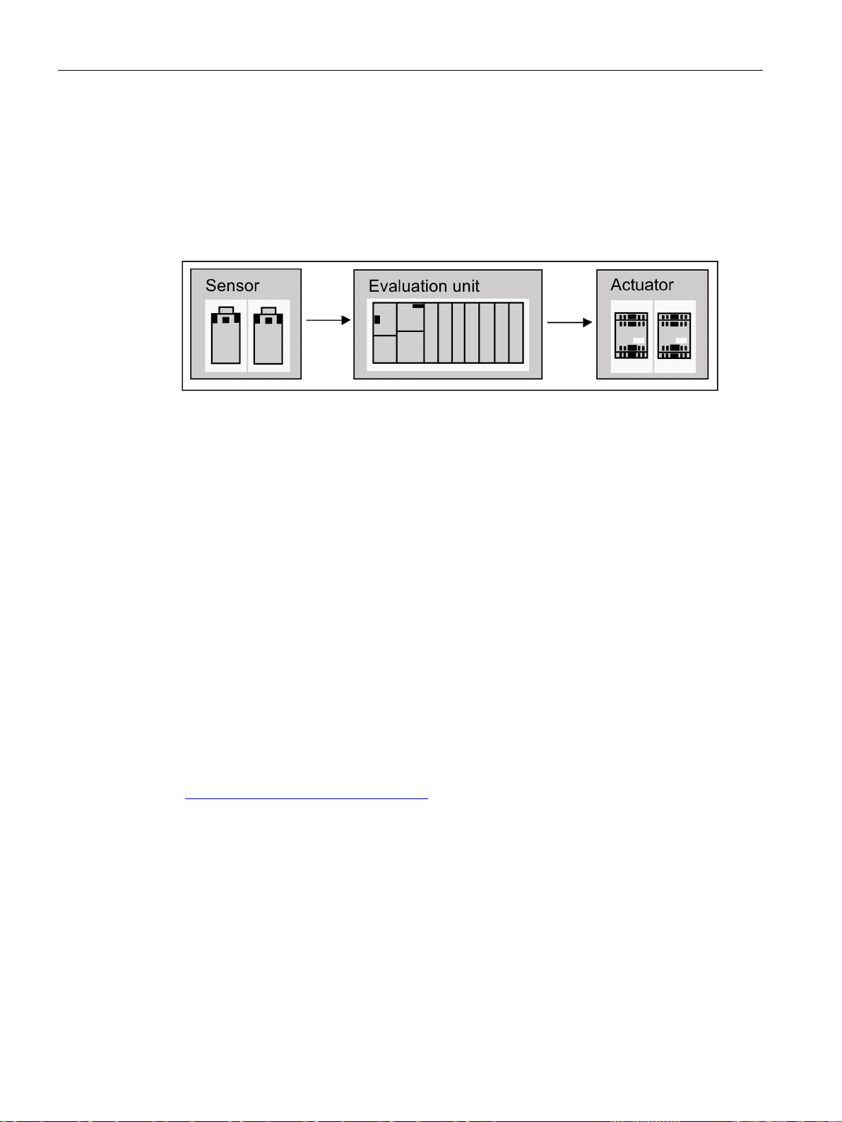
I/O configuration variants
6.2
Fail-safe operation
Ensuring functional safety
Safety of fail-safe SIMATIC Safety Integrated systems
Functions of a fail-safe CPU
S7 F/FH Systems
Fail-safe I/O modules (F-modules)
6.2 Fail-safe operation
A safety-related system encompasses sensors for signal acquisition, an evaluation unit for
processing the signals, and actuators for signal output.
Figure 6-1 Processing chain: acquire, process, output
All of the components contribute to the functional safety of the system, in order, when a
dangerous event occurs, to put the system into a safe state or to keep it in a safe state.
For SIMATIC Safety Integrated systems, the evaluation unit consists, for example, of failsafe single-channel CPUs and fail-safe dual-channel I/O modules. The fail-safe
communications take place via the safety-related PROFIsafe profile.
A fail-safe CPU has the following functions:
● Comprehensive self-tests and self-diagnostics check the fail-safe state of the CPU.
● Simultaneous execution of standard and safety programs on one CPU. When there are
changes to the standard user program, there are no unwanted effects on the safety
program.
The S7 F Systems optional package adds security functions to the CPU 410. The current
TÜV certificates are available on the Internet: TÜV certificates
(http://support.automation.siemens.com) under "Product Support".
F-modules have all of the required hardware and software components for safe processing
in accordance with the required safety class. This includes wire tests for short-circuit and
cross-circuit. You only program the user safety functions.
Safety-related input and output signals form the interface to the process. This enables, for
example, direct connection of single-channel and two-channel I/O signals from devices such
as EMERGENCY STOP buttons or light barriers.
CPU 410 Process Automation/CPU 410 SMART
58 System Manual, 05/2017, A5E31622160-AC
Page 59
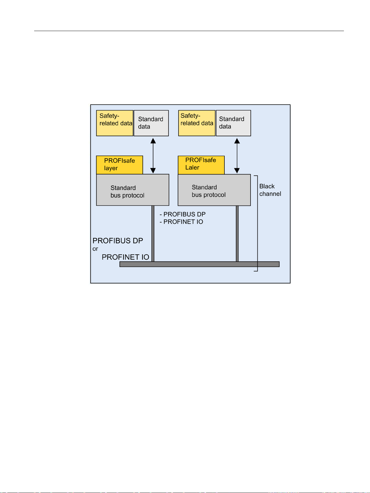
I/O configuration variants
Safety-related communication with PROFIsafe profile
6.2 Fail-safe operation
PROFIsafe was the first communication standard according to the IEC 61508 safety
standard that permits both standard and safety-related communication on one bus line. This
not only results in an enormous savings potential with regard to cabling and part variety, but
also the advantage of retrofit ability.
Figure 6-2 Safety-related communication
Safety-related and standard data are transmitted with PROFIsafe over the same bus line.
Black channel means that collision-free communication via a bus system with mediaindependent network components (also wireless) is possible.
PROFIsafe is an open solution for safety-related communication via standard fieldbuses.
Numerous manufacturers of safety components and end users of safety technology have
helped to develop this vendor-neutral and open standard for PROFIBUS International (PI).
The PROFIsafe profile supports safe communication for the open PROFIBUS and
PROFINET standard buses. An IE/PB Link ensures integrated, safety-related communication
between PROFIBUS DP and PROFINET IO.
PROFIsafe is is certified to IEC 61784-3 and meets the highest requirements for the
manufacturing and process industry.
PROFIBUS is the global standard for fieldbuses with approximately 13 million installed
nodes. Its market acceptance is so high because a large number of manufacturers offer
many products for PROFIBUS. With the PA transmission variant (IEC 1158-2), PROFIBUS
extends the unified system concept of distributed automation to the process world.
CPU 410 Process Automation/CPU 410 SMART
System Manual, 05/2017, A5E31622160-AC
59
Page 60

I/O configuration variants
Measure/
Error
Consecutive number
Time expectation with
acknowledgment
Identifier for sender
and receiver
Data backup CRC
Repetition
✓
Insertion
✓ ✓ ✓
Incorrect sequence
✓
Data falsification
✓
Delay
✓
(masquerade)
sequence)
See also
6.2 Fail-safe operation
PROFINET IO is the innovative and open Industrial Ethernet standard for automation. It
enables fast reaction times and transmission of large data quantities.
PROFIsafe uses the PROFIBUS or PROFINET IO services for safe communication. A failsafe CPU 410 and the fail-safe I/O exchange both user data as well as status and control
information; no additional hardware is required for this.
PROFIsafe takes the following measures to counteract the various possible errors when
transferring messages.
Table 6- 2 Measures in PROFIsafe for error avoidance
Loss ✓ ✓
Coupling of safetyrelated messages and
standard messages
FIFO errors (first-infirst-out data register
for maintaining the
✓ ✓ ✓
✓
S7 F Systems optional package
(http://support.automation.siemens.com/WW/view/en/35130252)
CPU 410 Process Automation/CPU 410 SMART
60 System Manual, 05/2017, A5E31622160-AC
Page 61
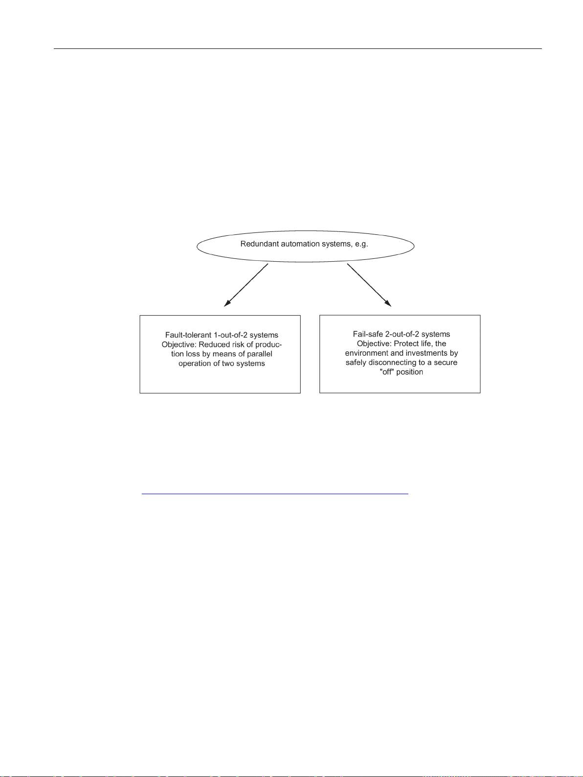
I/O configuration variants
6.3
Fault-tolerant automation systems (redundancy operation)
6.3.1
Redundant SIMATIC automation systems
Operating objectives of redundant automation systems
Why fault-tolerant automation systems?
Redundant I/O
6.3 Fault-tolerant automation systems (redundancy operation)
Redundant automation systems are used in practice with the aim of achieving a higher
degree of availability or fault tolerance.
Figure 6-3 Operating objectives of redundant automation systems
Note the difference between fault-tolerant and fail-safe systems.
The S7-400H is a fault-tolerant automation system. You may only use the S7-400H to
control safety-related processes if you have programmed it and assigned its parameters in
accordance with the rules for F-systems. You can find information on this in following
manual: SIMATIC Industrial Software S7 F/FH Systems
(http://support.automation.siemens.com/WW/view/en/2201072)
The purpose of using fault-tolerant automation systems is to reduce production downtimes,
regardless of whether the failures are caused by an error/fault or are due to maintenance
work.
The higher the costs of production stops, the greater the need to use a fault-tolerant system.
The generally higher investment costs of fault-tolerant systems are soon recovered since
production stops are avoided.
Input/output modules are termed redundant when they exist twice and they are configured
and operated as redundant pairs. The use of redundant I/O provides the highest degree of
availability, because the system tolerates the failure of a CPU or of a signal module.
CPU 410 Process Automation/CPU 410 SMART
System Manual, 05/2017, A5E31622160-AC
61
Page 62

I/O configuration variants
Single-channel switched I/O
See also
6.3.2
Increase of plant availability, reaction to errors
System-wide integration
Graduated availability by duplicating components
Redundancy nodes
one
6.3 Fault-tolerant automation systems (redundancy operation)
In single-channel switched configuration, there is one of each of the input/output modules. In
redundant operation, these modules can addressed by both subsystems. The single-channel
switched I/O configuration is recommended for system components which tolerate the failure
of individual modules.
Connection of two-channel I/O to the PROFIBUS DP interface (Page 80)
The CPU 410 and all other SIMATIC components, such as the SIMATIC PCS 7 control
system, are matched to one another. The system-wide integration, ranging from the control
room to the sensors and actuators, is implemented as a matter of course and ensures
maximum system performance.
The redundant structure of the S7-400H ensures requirements to reliability at all times. This
means: all essential components are duplicated.
This redundant structure includes the CPU, the power supply, and the hardware for linking
the two CPUs.
You yourself decide on any other components you want to duplicate to increase availability
depending on the specific process you are automating.
Redundant nodes represent the fail safety of systems with redundant components. A
redundant node can be considered as independent when the failure of a component within
the node does not result in reliability constraints in other nodes or in the overall system.
The availability of the overall system can be illustrated simply in a block diagram. With a 1out-of-2 system,
operability of the overall system. The weakest link in the chain of redundant nodes
determines the availability of the overall system
component of the redundant node may fail without impairing the
CPU 410 Process Automation/CPU 410 SMART
62 System Manual, 05/2017, A5E31622160-AC
Page 63
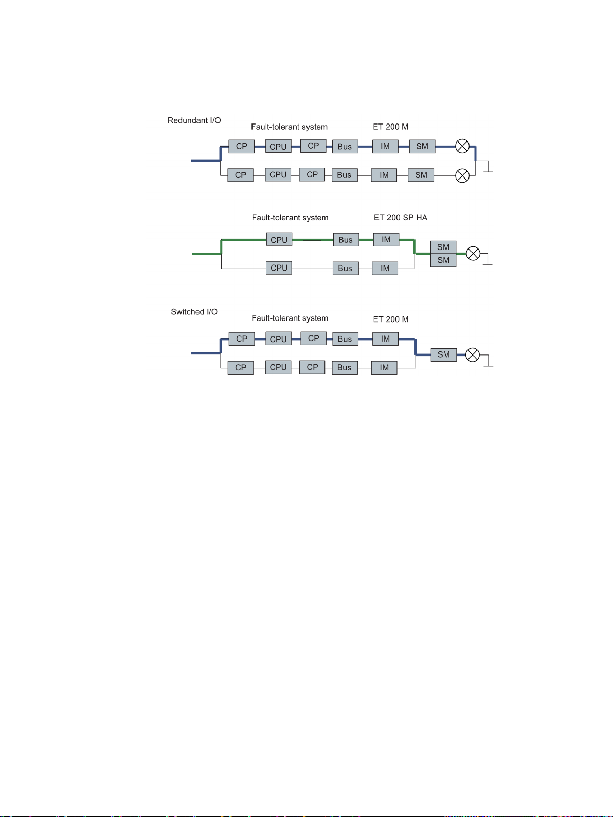
I/O configuration variants
No error/fault
6.3 Fault-tolerant automation systems (redundancy operation)
Figure 6-4 Example of redundancy in a network without error
CPU 410 Process Automation/CPU 410 SMART
System Manual, 05/2017, A5E31622160-AC
63
Page 64
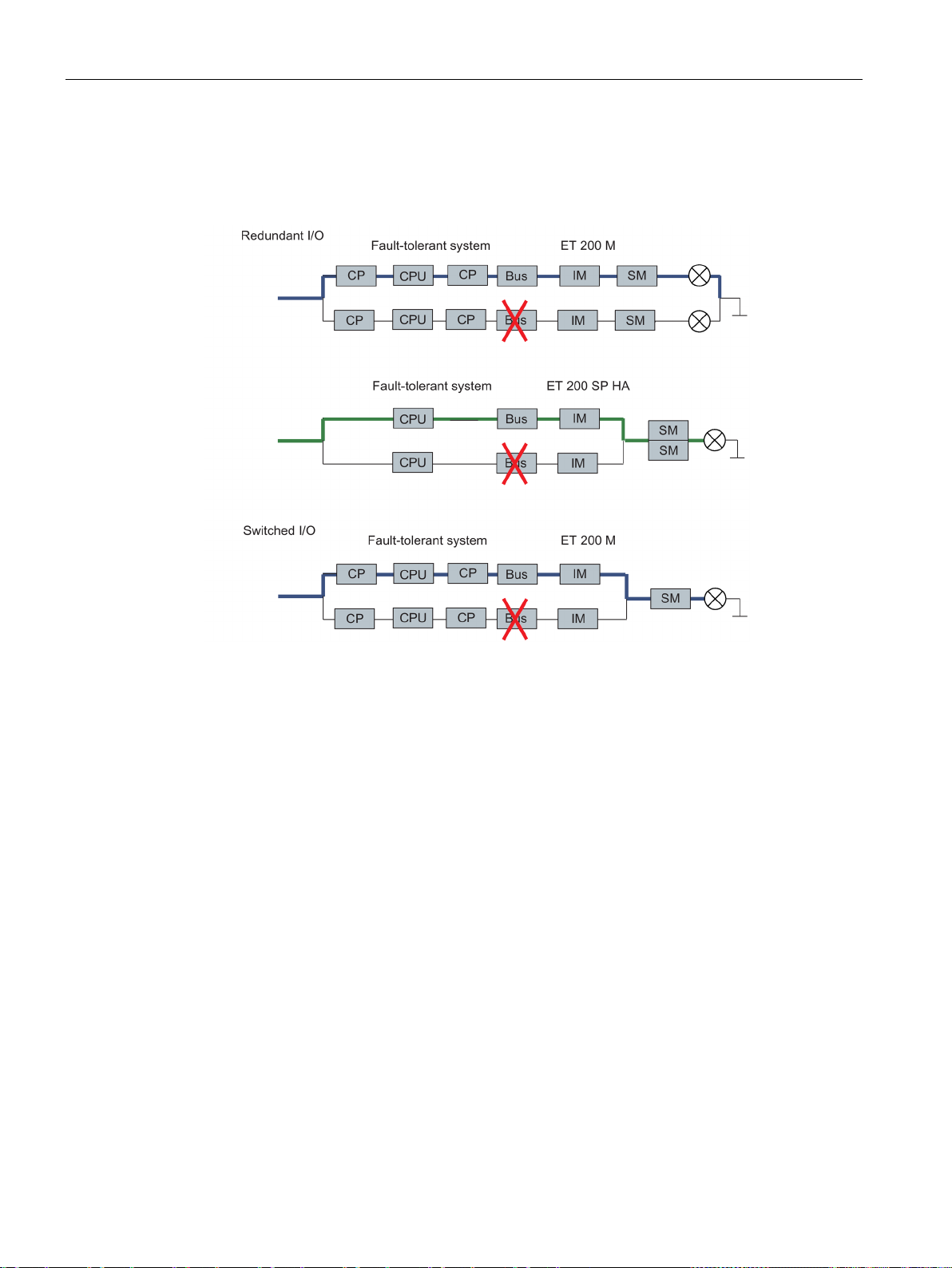
I/O configuration variants
With error/fault
6.3 Fault-tolerant automation systems (redundancy operation)
The following figure shows how a component may fail without impairing the functionality of
the overall system.
Figure 6-5 Example of redundancy in a 1-out-of-2 system with error
CPU 410 Process Automation/CPU 410 SMART
64 System Manual, 05/2017, A5E31622160-AC
Page 65
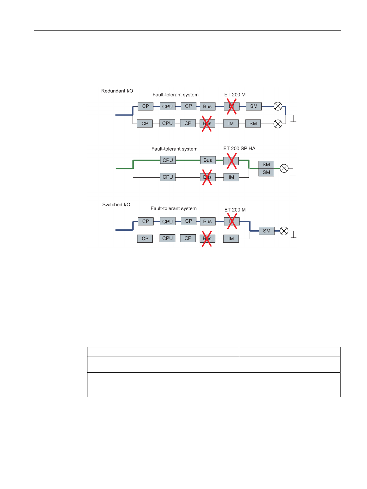
I/O configuration variants
Failure of a redundant node (total failure)
6.4
Introduction to the I/O link to fault-tolerant system
I/O installation types
Configuration
Availability
or switched I/O
switched I/O
Redundant I/O
High
6.4 Introduction to the I/O link to fault-tolerant system
The following figure shows that the overall system is no longer operable, because both
subunits have failed in a 1-out-of-2 redundancy node (total failure).
Figure 6-6 Example of redundancy in a 1-out-of-2 system with total failure
In addition to the power supply module and CPUs, which are always redundant, the
operating system supports the following I/O installation types. You specify the I/O installation
types when configuring in HW Config.
Fault-tolerant PROFINET IO (S2 with system redundancy)
Redundant PROFINET IO (R1 with system redundancy) or
Enhanced
Enhanced
CPU 410 Process Automation/CPU 410 SMART
System Manual, 05/2017, A5E31622160-AC
65
Page 66

I/O configuration variants
Note
IO redundancy
The term IO redundancy is als
Addressing
6.5
Using single-channel switched I/O
What is single-channel switched I/O?
all switched I/O
6.5 Using single-channel switched I/O
o used for the connection of a redundant I/O to PROFINET IO
If you are using an I/O in a system-redundant configuration, you always use the same
address when addressing the I/O.
In single-channel switched configuration, there is one of each of the input/output modules.
In redundant operation, these can addressed by both subsystems.
In stand-alone operation, the master subsystem always addresses
contrast to one-sided I/O).
The single-channel switched I/O configuration is recommended for system components
which tolerate the failure of individual modules within the ET 200M, ET 200iSP or ET 200SP
HA.
(in
CPU 410 Process Automation/CPU 410 SMART
66 System Manual, 05/2017, A5E31622160-AC
Page 67

I/O configuration variants
Single-channel switched I/O configuration at the PROFIBUS DP interface
Interface module
Article No.
IM 152 for ET 200iSP
6ES7152-1AA00-0AB0
6ES7153-2BA02-0XB0
6.5 Using single-channel switched I/O
The installation with single-channel switched I/O is possible with the ET 200M distributed I/O
device with active backplane bus and redundant PROFIBUS DP slave interface and with the
ET 200iSP distributed I/O device.
Figure 6-7 Single-channel switched distributed I/O configuration at the PROFIBUS DP interface
You can use the following interface modules for the I/O configuration at the PROFIBUS DP
interface:
Table 6- 3 Interface modules for use of single-channel switched I/O configuration at the PROFIBUS
DP interface
IM 153-2 for ET 200M 6ES7153-2BA82-0XB0
Each S7-400H subsystem is interconnected with one of the two DP slave interfaces of the
ET 200M over a DP master interface.
CPU 410 Process Automation/CPU 410 SMART
System Manual, 05/2017, A5E31622160-AC
67
Page 68

I/O configuration variants
Bus modules for hot swapping
Bus module
Article No.
and IM 153
width
design of redundant systems
DP/PA link
DP/PA link
Article No.
6ES7153-2BA70-0XB0
Y-Link
Y-Link
Article No.
6ES7153-2BA70-0XB0
6.5 Using single-channel switched I/O
You can use the following bus modules for hot swapping a variety of components:
Table 6- 4 Bus modules for hot swapping
BM PS/IM for load power supply
BM 2 x 40 for two modules with 40
mm width
BM 1 x 80 for a module with 80 mm
BM IM/IM for two IM 153-2/2 FO for
The DP/PA link consists of one or two IM 153-2 interface modules, and one to five DP/PA
couplers that are either connected with one another via passive bus couplers or via bus
modules.
The DP/PA link creates a gateway from a PROFIBUS DP master system to PROFIBUS PA.
In this case the two bus systems are non-interacting through the IM 153-2 both physically
(galvanically) and in terms of protocols and time.
PROFIBUS PA can be connected to a redundant system via a DP/PA link. The following IM
157 PA coupler is permissible: 6ES7157-0AC83-0XA0
You can use the following DP/PA links:
6ES7195-7HA00-0XA0
6ES7195-7HB00-0XA0
6ES7195-7HC00-0XA0
6ES7195-7HD10-0XA0
ET 200M as DP/PA link with 6ES7153-2BA82-0XB0
6ES7153-2BA81-0XB0
The Y Link consists of two IM 153-2 interface modules and one Y coupler that are connected
with one another by bus modules.
The Y Link creates a gateway from the redundant DP master system of an S7-400H to a
non-redundant DP master system. This means that devices with only one PROFIBUS DP
interface can be connected to a S7-400H as switched I/Os.
A single-channel DP master system can be connected to a redundant system via a Y
coupler.
The following IM 157 Y coupler is permissible: 6ES7197-1LB00 0XA0.
You can use the following Y-Links:
ET 200M as Y-Link with 6ES7153-2BA82-0XB0
CPU 410 Process Automation/CPU 410 SMART
68 System Manual, 05/2017, A5E31622160-AC
Page 69

I/O configuration variants
FF Link
FF Link
FDC 157
6ES7157-0AC85-0XA0
Rule for PROFIBUS DP
6.5 Using single-channel switched I/O
The FF Link bus link is a gateway between a PROFIBUS DP master system and a
FOUNDATION Fieldbus H1 segment and thus enables the integration of FF devices in
SIMATIC PCS 7. The two bus systems are uncoupled from each other by the IM 153-2 FF
both physically (galvanically) and with respect to protocol and time.
The FF Link bus link consists of one or two IM 153-2 FF interface modules and an FDC 157
field device coupler or a redundant FDC 157 coupler pair, which are connected to one
another via passive bus connectors or, in the case of the redundant installation, via bus
modules.
The Compact FF Link bus link consists of one or two IM 655-5 FF interface modules.
IM 153-2
Compact FF Link 6ES7655-5BA00-0AB0
A single-channel switched I/O configuration must always be symmetrical.
● This means the fault-tolerant CPU and other DP masters must be installed in the same
slots in both subsystems (for example slot 4 in both subsystems) or
● The DP slaves must be connected to the same DP interface in both subsystems (for
example to the PROFIBUS DP interfaces of both fault-tolerant CPUs).
6ES7153-2DA80-0XB0
CPU 410 Process Automation/CPU 410 SMART
System Manual, 05/2017, A5E31622160-AC
69
Page 70
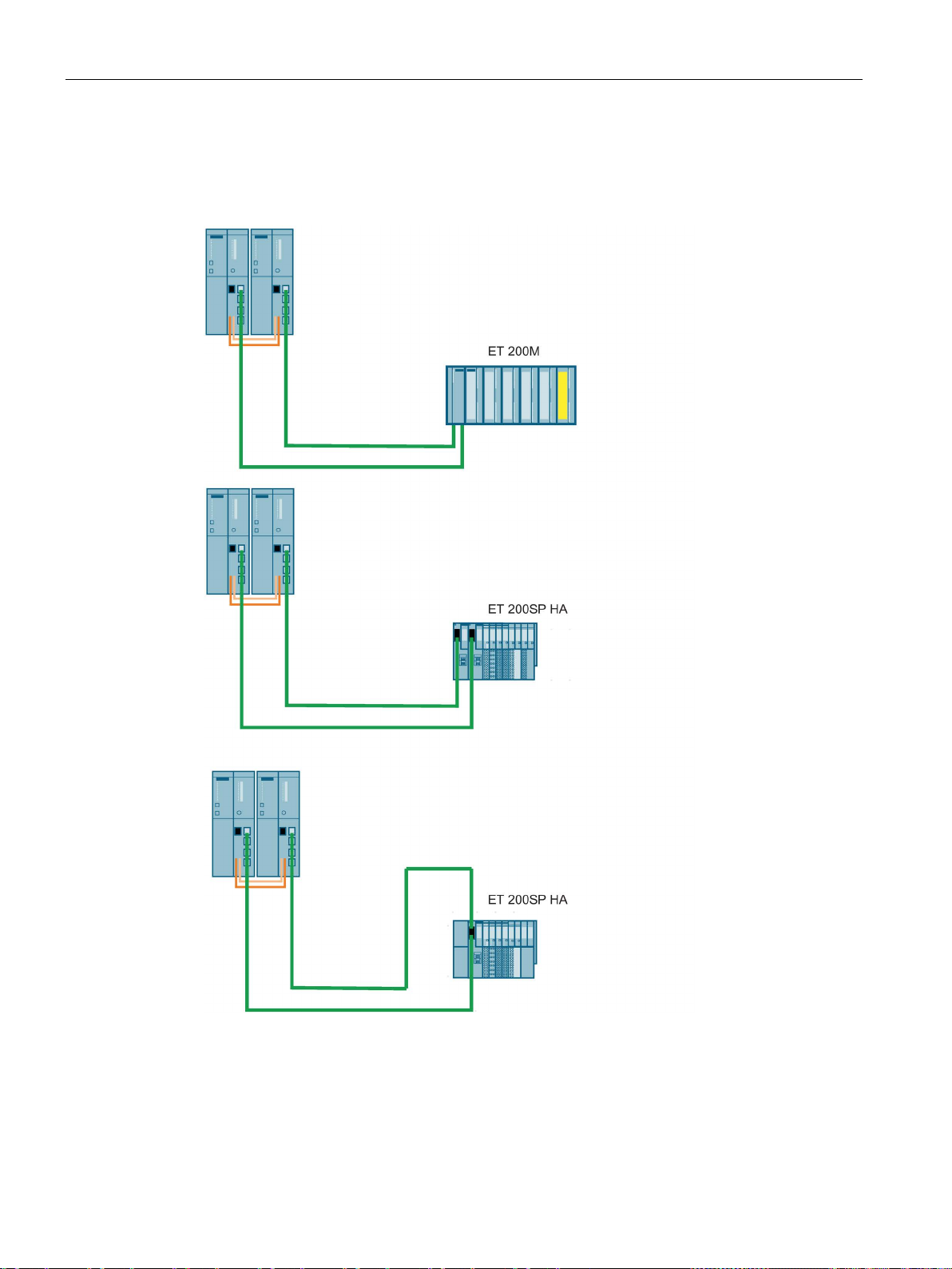
I/O configuration variants
Single-channel switched I/O configuration at the PROFINET IO interface
6.5 Using single-channel switched I/O
The installation with single-channel switched I/O is possible with the ET 200M and ET 200SP
HA distributed I/O devices with active backplane bus and redundant PROFINET IO interface.
Figure 6-8 Single-channel switched distributed I/O configuration at the PROFINET IO interface
Each subsystem of the S7-400H is connected (over a PROFINET IO interface) to the
PROFINET IO interface of the ET 200M or ET 200SP HA over one connection each. If the
two PROFINET IO interfaces are located on one IM, this is known as an S2 configuration.
The S stands for a single (single) IM and thus for only one PROFINET IO interface. If the
CPU 410 Process Automation/CPU 410 SMART
70 System Manual, 05/2017, A5E31622160-AC
Page 71

I/O configuration variants
Interface module
Article No.
IM 153-4 PN V4.0 and higher
6ES7153-4BA00-0XB0
Single-channel switched I/O and user program
active
channel
passive channel
Failure of the single-channel switched I/O
6.5 Using single-channel switched I/O
PROFINET IO interfaces are located on two different IMs, this is known as an R1
configuration The R stands for redundant IMs and thus for two PROFINET IO interfaces. See
Chapter Communication services (Page 308).
You can use the following interface module for the I/O configuration at the PROFINET IO
interface:
Table 6- 5 Interface module for use of single-channel switched I/O configuration at the PROFINET
IO interface
IM 155-6 PN HA 6DL1155-6AU00-0PM0
In redundant operation, in principle any subsystem can access single-channel switched I/O.
The data is automatically transferred via the synchronization link and compared. An identical
value is available to the two subsystems at all times owing to the synchronized access.
If you have connected the I/O over two IMs, the CPU accesses the I/O over one IM. The
active IM is indicated by illumination of the ACT LED.
The path via the currently active DP interface or PROFINET IO interface is called the
, while the path via the other interface is called the
cycle is always active on both channels. However, only the input and output values of the
active channel are processed in the user program or output to the I/O. The same applies to
asynchronous activities, such as interrupt processing and the exchange of data records.
The fault-tolerant system with single-channel switched I/O responds to errors as follows:
● The faulty I/O is no longer available if an input/output module or a connected device fails.
● In certain failure situations (for example failure of a subsystem, a DP master system or an
IM153-2 DP slave interface), the single-channel switched I/O continues to be available for
the process.
This is achieved by a changeover between active and passive channel. This changeover
takes place separately for each DP or PNIO station. A distinction is made between the
following two types of failure:
– Failures affecting only one station (such as failure of the DP slave interface of the
channel currently active)
– Failures affecting all stations of a DP master system or PNIO system
. The DP or PNIO
CPU 410 Process Automation/CPU 410 SMART
System Manual, 05/2017, A5E31622160-AC
These include removal of the connector at the DP master interface or PNIO interface,
shutdown of the DP master system (for example a RUN-STOP transition on a CP 443-
5), and short-circuits at the cable harness of a DP master system or PNIO system.
The following applies to each station affected by a failure: If both DP slave interfaces or PN
IO connections are functional and the active channel fails, the channel previously passive
automatically becomes the active channel. A redundancy loss is reported to the user
program when OB 70 starts (event W#16#73A3).
71
Page 72

I/O configuration variants
Note
If the external DP master interface module can detect failure of the entire DP master system
(due to a short
nt ("Master system failure entering
state" W#16#39C3). The operating system no longer reports individual station failures. This
feature can be used to accelerate the changeover between the active and passive channel.
Duration of a changeover of the active channel
Note
When using fail
longer than the changeover time of
ignore this rule, you risk passivation of the fail
active channel.
You can use the Excel file "s7ftimea.xls" to calculate the monitoring and reaction times.
file is available at the following address:
http://support.automation.siemens.com/WW/view/en/22557362
Note
Please note that the CPU can only detect a signal change if the signal duration is greater
than the specified changeover time.
When there is
slowest DP component applies to all DP components. A DP/PA link or Y
determines the changeover time and the corresponding minimum signal duration. We
therefore recommend t
6.5 Using single-channel switched I/O
Once the problem is eliminated, redundancy is restored. This also starts OB 70 (event
W#16#72A3). In this situation, there is no changeover between the active and passive
channel.
If one channel has already failed, and the remaining (active) channel also fails, then there is
a complete station failure. This starts OB 86 (event W#16#39C4).
There is also complete station failure if an IM fails in an S2 configuration. This starts OB 86
(event W#16#39C4).
-circuit, for example), it reports only this eve
The maximum changeover time is
DP/PN error detection time + DP/PN changeover time + changeover time of the DP slave
interface/PNIO interface
You can determine the first two values from the bus parameters of your DP master system or
PNIO system in STEP 7. You determine the last two values using the manuals of the DP
slave interfaces or PNIO interfaces in question.
-safe modules, always set a monitoring time for each fail-safe module that is
the active channel in the fault-tolerant system. If you
-safe modules during the changeover of the
The
a changeover of the entire DP master system, the changeover time of the
-Link usually
hat you connect DP/PA and Y-Links to a separate DP master system.
CPU 410 Process Automation/CPU 410 SMART
72 System Manual, 05/2017, A5E31622160-AC
Page 73

I/O configuration variants
Changeover of the active channel during link-up and updating
Bumpless changeover of the active channel
System configuration and project engineering
See also
6.6
Versions of I/O connection to the PROFINET IO interface
6.6.1
Use of I/O connected to the PROFINET IO interface, system redundancy
System redundancy
Note
The PROFINET IO device must support this function in order to be operated redundantly on
the fault
created, thereby achieving system redundancy.
6.6 Versions of I/O connection to the PROFINET IO interface
During link-up and updating with master/standby changeover (see Link-up sequence
(Page 346)), a changeover between the active and passive channels occurs for all stations
of the switched I/O. At the same time OB 72 is called.
To prevent the I/O failing temporarily or outputting substitute values during the changeover
between the active and passive channel, the DP or PNIO stations of the switched I/O put
their outputs on hold until the changeover is completed and the new active channel has
taken over.
To ensure that total failure of a DP or PNIO station is also detected during the changeover,
the changeover is monitored by both the various DP/PNIO stations and by the DP master
system or IO system.
You should allocate switched I/O with different changeover times to separate chains. This,
for example, simplifies the calculation of monitoring times.
Time monitoring (Page 120)
You can configure the PROFINET IO system redundancy with switched devices connected
to an IM. The configuring of the PROFINET I/O is comparable to the configuring of the
PROFIBUS I/O.
You can connect a maximum of 256 IO devices to each of the two integrated PN/IO
interfaces. You can configure these as one-sided or switched devices as desired. The station
numbers are disjoint across both PN/IO interfaces and are between 1 and 256.
-tolerant system. Two ports does not mean that two system connections can be
CPU 410 Process Automation/CPU 410 SMART
System Manual, 05/2017, A5E31622160-AC
73
Page 74
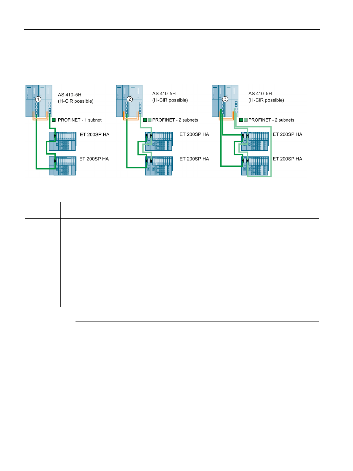
I/O configuration variants
Configuration
Configuration
Properties
This type of connection is also known as fault-tolerant PROFINET IO.
②
tolerant system. Each IM is assigned
③
Note
Logical configuration and topology
The topology alone does not determine whether IO devices are configured at one side
(assigned to only one CPU in
configuration. This is specified in configuration. The IO devices in configuration
example, also be configured on one side instead of in a system
6.6 Versions of I/O connection to the PROFINET IO interface
The following figure shows various different configurations for connecting IO devices to the
fault-tolerant system.
Figure 6-9 System redundancy
①
and ③
Switched I/O at the PROFINET IO
Each IO device is connected over one IM with two logic connections (system redundancy) to the two CPUs
in the fault-tolerant system.
Switched I/O at the redundant PROFINET IO
Each IO device is connected over two IMs to the two CPUs in the fault-
to one of the CPUs. The IM must support system redundancy.
This type of connection is also known as redundant PROFINET IO.
This allows independent redundant PROFINET networks to operate in the fault-tolerant system. At the
same time, the two IMs increase availability.
, the connection to the CPU is also configured as a ring (redundant fault-tolerant PROFINET IO).
In
the fault-tolerant system) or in a system-redundant
① can, for
-redundant configuration.
CPU 410 Process Automation/CPU 410 SMART
74 System Manual, 05/2017, A5E31622160-AC
Page 75

I/O configuration variants
Configuration with two IO devices with independent, system-redundant connection
Network addresses on the PROFINET IO subsystem
Commissioning of a system-redundant configuration
Note
To edit the topology of a project, use the topology editor in HW Config.
S2 and R1 devices
6.6 Versions of I/O connection to the PROFINET IO interface
This configuration has the following advantage: The complete system can continue operating
after a wire break, no matter where the wire break is located. One of the two communication
connections of the IO devices is always retained. The IO devices that are redundant up this
point continue operating as one-sided IO devices.
In a redundant configuration, the network addresses of the interface modules must be
unique across both PROFINET IO subsystems.
● In a ring structure, all network addresses must be within a PROFINET IO subsystem and
you must specify the MRP role for each node.
● In the case of system redundancy with two subnets, the two interface modules of a
station must be assigned to the following PROFINET IO subnet:
– Interface module in slot 0 of the IO device is assigned to rack 0 of the IO controller.
– Interface module in slot 1 of the IO device is assigned to rack 1 of the IO controller.
It is imperative that you assign unique names when commissioning.
When you change a project or download a new project, follow these steps:
1. Put the fault-tolerant system in STOP state on both ends
2. Perform a memory reset of the standby CPU
3. Download the new project to the master CPU
4. Start the Fault-tolerant system
S2 device: There is one IM connected to both CPUs.
R1 device: There are two IM (redundant). Each IM is connected to one CPU.
CPU 410 Process Automation/CPU 410 SMART
System Manual, 05/2017, A5E31622160-AC
75
Page 76
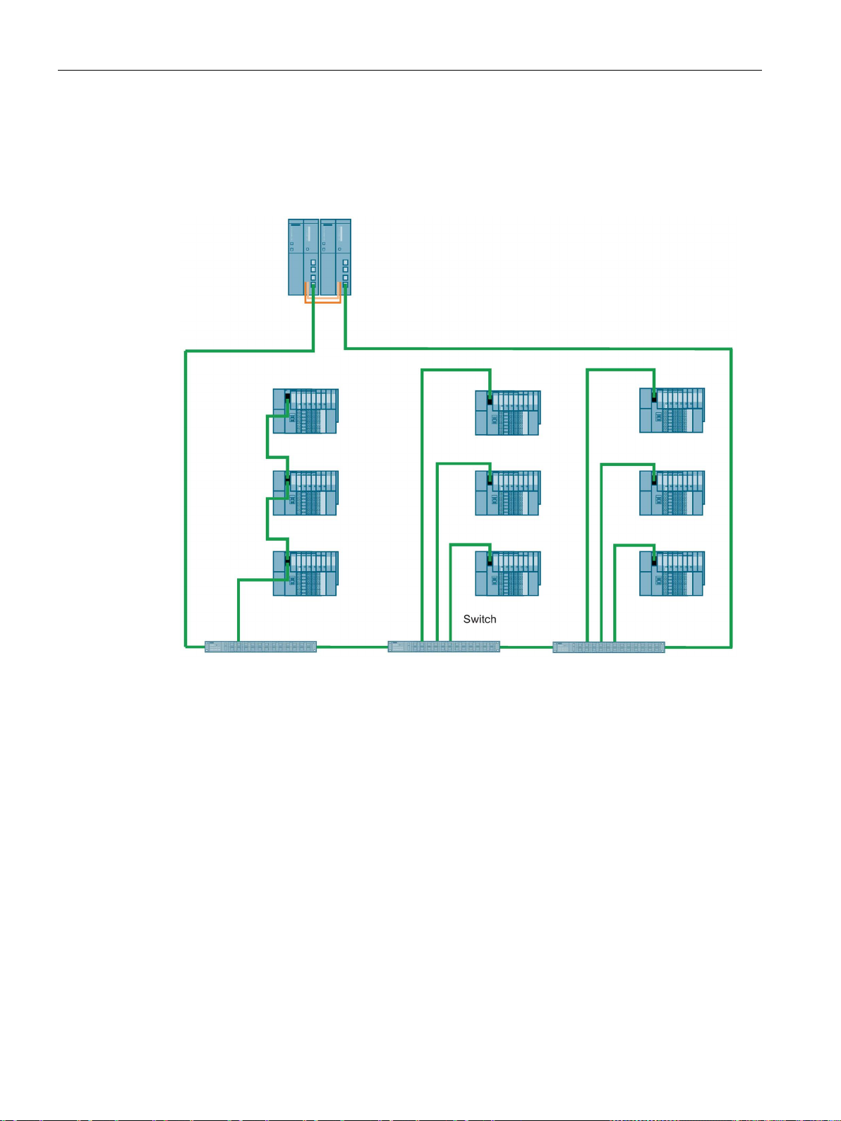
I/O configuration variants
Cabinet concept with switched I/O connected to PROFINET IO
6.6.2
Redundant I/O in an ET 200SP HA
Redundant I/O
6.6 Versions of I/O connection to the PROFINET IO interface
The following figure shows the system-redundant connection of nine IO devices via three
switches. With this configuration, for example, IO devices can be arranged in multiple
cabinets.
Figure 6-10 IO devices in multiple cabinets
To configure the redundant I/O connected to PROFINET IO, insert two I/O modules of the
same type next to each other in a special terminal block (TB45R...).
CPU 410 Process Automation/CPU 410 SMART
76 System Manual, 05/2017, A5E31622160-AC
Page 77

I/O configuration variants
Application planning
Hardware rule
Mounting rule
TB45R
Note
Specific wiring
Always read the documentation of the I/O module used.
Configuring
6.6 Versions of I/O connection to the PROFINET IO interface
This terminal block connects the respective process signals of the two IO modules to a
common process terminal.
● There is less wiring work compared to connecting separate I/O modules, because the
interconnection of the process signals is integrated in the system.
● The redundant signal processing of the sensors and actuators on the module level
increases the availability of the system.
● In redundant operation, the switching characteristics of the output modules that can
control the actuator in parallel are improved.
Observe the following rules for configuring redundant I/O modules:
● The I/O modules must be approved for redundant operation. You can find this information
in the manual for the respective module.
● Redundantly deployed I/O modules must be identical, i.e. they must have the same article
number, the same hardware version and the same firmware version.
I/O modules of the same type are plugged in pairs next to each other in the same IO device.
● Both slots are located on the same support module.
● Both slots are located on the same terminal block (
).
● Configure redundancy for the I/O module.
The settings you make for an I/O module always apply to the module pair.
CPU 410 Process Automation/CPU 410 SMART
System Manual, 05/2017, A5E31622160-AC
77
Page 78
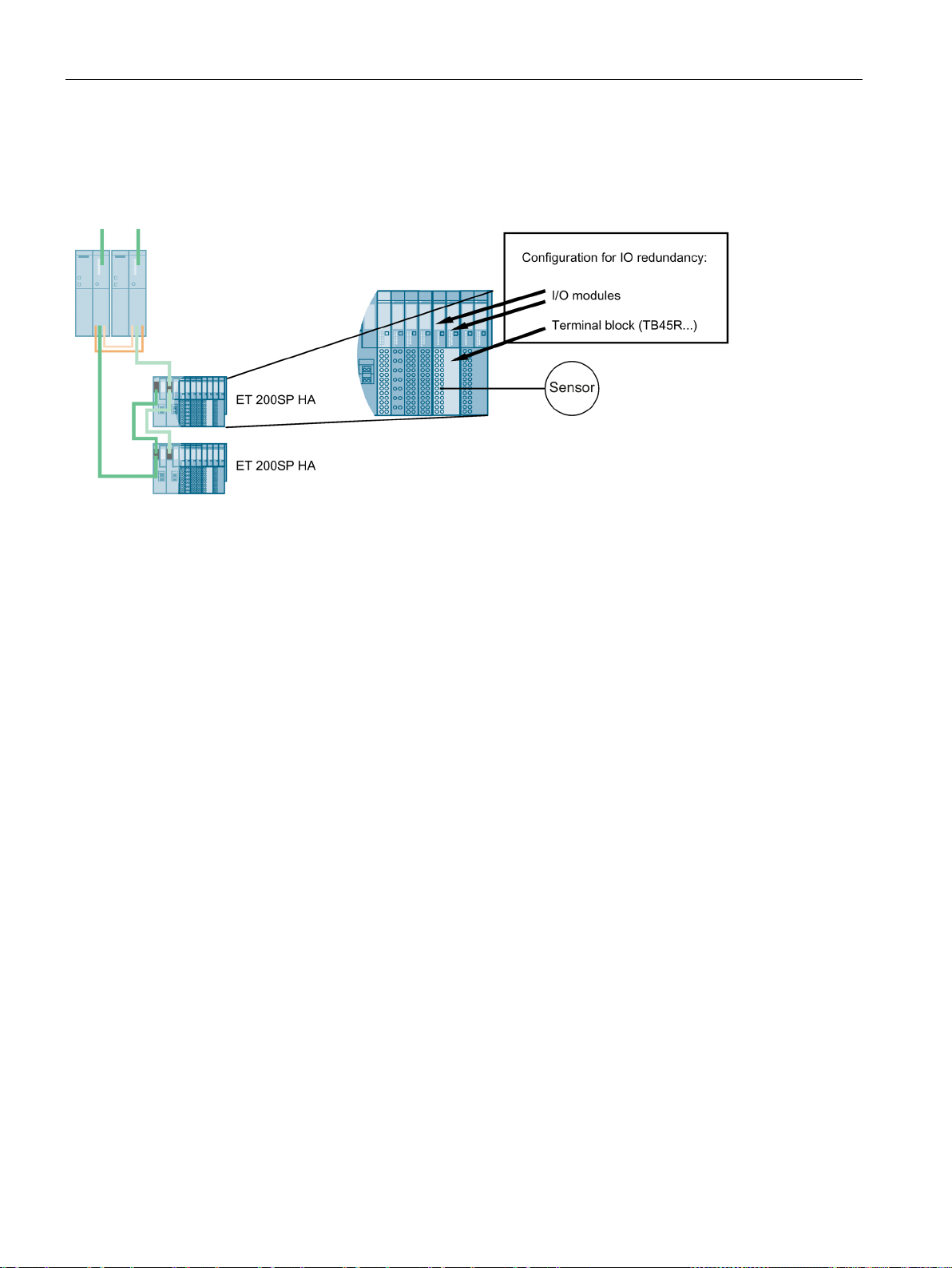
I/O configuration variants
Configuration
Response to failure
Connecting sensors/actuators
6.6 Versions of I/O connection to the PROFINET IO interface
The following figure shows an example for the connection of the sensors or actuators each
with two redundantly used input/output modules.
Figure 6-11 S7-400 H-system with sensors and actuators on module pairs (redundant signal processing)
The following applies when a I/O module or a channel of the two I/O modules fails (valid for
input/output and mixed modules):
● The inputs continue to be available in the system.
● The outputs are controlled in the system.
You can connect a sensor/actuator to two redundant input/output modules.
The failure of an input module does not result in the loss of sensor data. When an output
module fails, the connected actuator continues to be controlled.
In some cases, the hardware design requires the sensor also to be implemented
redundantly, for example for RTD thermal resistors. Sensors can be powered using suitable
input modules.
The redundant signal processing of the sensors and actuators at the module level increases
the availability of the system. Firmware update and module replacement are possible during
operation.
In redundant operation, the switching characteristics of the output modules that can control
the actuator in parallel are improved. The modules can operate with twice the switching
current and power distribution between two output modules.
The figure below shows a configuration with one sensor and one actuator for a pair of
redundant I/O modules.
CPU 410 Process Automation/CPU 410 SMART
78 System Manual, 05/2017, A5E31622160-AC
Page 79
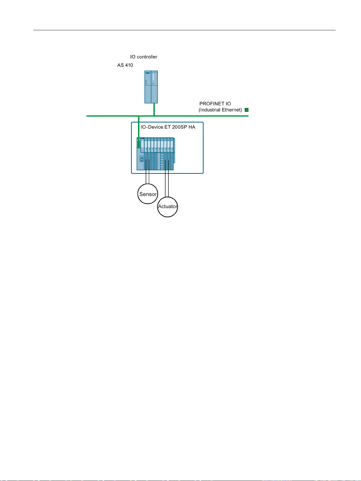
I/O configuration variants
Maintenance and service
6.6 Versions of I/O connection to the PROFINET IO interface
Figure 6-12 AS 410 with redundant module pairs
One of the following functions is possible in each case during operation:
● Firmware update
● Replacing a module
CPU 410 Process Automation/CPU 410 SMART
System Manual, 05/2017, A5E31622160-AC
79
Page 80
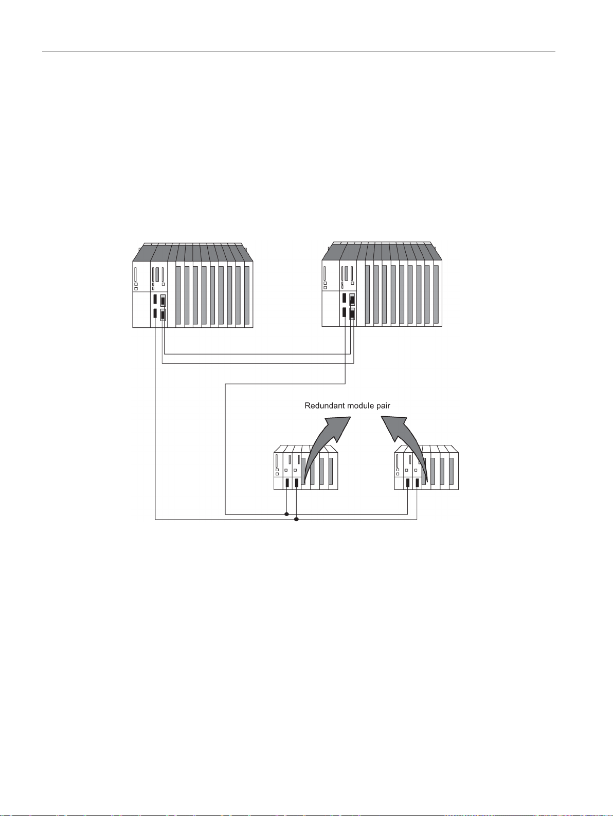
I/O configuration variants
6.7
Connection of two-channel I/O to the PROFIBUS DP interface
6.7.1
Connecting redundant I/O
Redundant I/O in the switched DP slave
6.7 Connection of two-channel I/O to the PROFIBUS DP interface
To achieve this, the signal modules are installed in pairs in ET 200M distributed I/O devices
with active backplane bus.
Figure 6-13 Redundant I/O in the switched DP slave
CPU 410 Process Automation/CPU 410 SMART
80 System Manual, 05/2017, A5E31622160-AC
Page 81

I/O configuration variants
Principle of channel group-specific redundancy
Note
Channel and channel group
Depending on the module, a
channels, or all channels of the module. You can therefore operate all modules with
redundancy capability in channel group
"Functional I/O redundancy" block library
Using the blocks
6.7 Connection of two-channel I/O to the PROFIBUS DP interface
Channel errors due to discrepancy cause the passivation of the respective channel. Channel
errors due to diagnostic interrupts (OB82) cause the passivation of the channel group
affected. Depassivation depassivates all affected channels as well as the modules
passivated due to module errors. Channel group-specific passivation significantly increases
availability in the following situations:
● Relatively frequent encoder failures
● Repairs that take a long time
● Multiple channel errors on one module
channel group contains a single channel, a group of several
-specific redundancy mode.
You can find an up-to-date list of modules with redundancy capability in Signal modules for
redundancy (Page 83).
The blocks you use for channel group-specific redundancy are located in the "Redundant IO
CGP V50" library.
The "Functional I/O redundancy" block libraries that support the redundant I/O each contain
the following blocks:
● FC 450 "RED_INIT": Initialization function
● FC 451 "RED_DEPA": Initiate depassivation
● FB 450 "RED_IN": Function block for reading redundant inputs
● FB 451 "RED_OUT": Function block for controlling redundant outputs
● FB 452 "RED_DIAG": Function block for diagnostics of redundant I/O
● FB 453 "RED_STATUS": Function block for redundancy status information
Configure the numbers of the management data blocks for the redundant I/O in HW Config
under "CPU properties -> Fault-tolerant parameters". Assign unassigned DB numbers for
these data blocks. The data blocks are created by FC 450 "RED_INIT" during CPU startup.
The default setting for the management data block numbers is 1 and 2. These data blocks
are not the instance data blocks of FB 450 "RED_IN" or FB 451 "RED_OUT".
You can open the libraries in the SIMATIC Manager with "File -> Open -> Libraries"
The relevant online help describes the functions and use of the blocks.
Before using the blocks, configure the redundant modules as redundant in HW Config.
CPU 410 Process Automation/CPU 410 SMART
System Manual, 05/2017, A5E31622160-AC
81
Page 82

I/O configuration variants
Block
OB
Depassivation is delayed by 10 s.
Note
Use of FB 450 "RED_IN" and 451 "RED_OUT" when using process image partitions
For each priority class used (OB 1, OB 30 ... OB 38), you must use a separate process
image partition.
6.7 Connection of two-channel I/O to the PROFIBUS DP interface
The OBs into which you need to link the various blocks are listed in the table below:
FC 450 "RED_INIT"
FC 451 "RED_DEPA" If you call FC 451 in OB 83 while inserting modules or in OB 85 dur-
FB 450 "RED_IN"
FB 451 "RED_OUT"
FB 452 "RED_DIAG"
FB 453 "RED_STATUS"
• OB 72 "CPU redundancy error" (only with fault-tolerant systems)
FC 450 is only processed after start event
B#16#33:"Standby/master switchover by operator"
• OB 80 "Timeout error" (only in single mode)
FC 450 is only executed after the start event "Resume RUN after
reconfiguring"
• OB 100 "Restart" (the administration DBs are recreated, see the
online help)
• OB 102 "Cold restart"
ing alarm output, depassivation is delayed by approximately 3 seconds.
In addition the FC 451 should be executed after the removal of the
error response as specific call in OB 1 and/or OB 30 to 38. The
FC451 only depassivates modules in the corresponding process
image partition.
• OB 1 "Cyclic program"
• OB 30 to OB 38 "Watchdog interrupt"
• OB 1 "Cyclic program"
• OB 30 to OB 38 "Watchdog interrupt"
• OB 72 "CPU redundancy error"
• OB 82 "Diagnostic interrupt"
• OB 83 "Remove/insert interrupt"
• OB 85 "Program execution error"
• OB 1 "Cyclic program" (fault-tolerant systems only)
• OB 30 to OB 38 "Watchdog interrupt"
To be able to address redundant modules using process image partitions in watchdog
interrupts, the relevant process image partition must be assigned to this pair of modules and
to the watchdog interrupt. Call FB 450 "RED_IN" in this watchdog interrupt before you call
the user program. Call FB 451 "RED_OUT" in this watchdog interrupt after you call the user
program.
The valid values that can be processed by the user program are always located at the lower
address of both redundant modules. This means that only the lower address can be used for
the application; the values of the higher address are not relevant for the application.
CPU 410 Process Automation/CPU 410 SMART
82 System Manual, 05/2017, A5E31622160-AC
Page 83

I/O configuration variants
HW configuration and configuring the redundant I/O
Note
System modifications during operation are also supported with redundant I/O. You are
not permitted to change the parameter settings for a redundant module per SFC.
Note
Always swit
module that does not support diagnostics functions and is not passivated. You might
otherwise passivate the wrong module. This procedure is necessary, for example, when
replaci
Redundant modules must be in the process image of the inputs or outputs. Redundant
modules are always accessed using the process image.
If you use redundant modules, you need to make the following settings on
"Cycle/clock memory" tab under "HW Config
"OB 85 call on I/O area access error > Only incoming and outgoing errors"
6.7.2
Signal modules for redundancy
Signal modules as redundant I/O
Note
The statements on the individual signal modules in this section refer e
in redundant operation. Restrictions and special features listed here especially do not apply
to the use of the corresponding module in stand
6.7 Connection of two-channel I/O to the PROFIBUS DP interface
Follow the steps below to use redundant I/O:
1. Insert all the modules you want to operate redundantly. Please also observe the default
rules for configuration detailed below.
2. Configure module redundancy in HW Config in the object properties of the relevant
module.
Either search for a partner module for each module or use the default settings.
If the module is inserted in the slave with a DP address at slot X, the module in the slave
with the next Profibus address at slot X will be suggested.
3. Enter the remaining redundancy parameters for the input modules.
ch off power to the station or rack before you remove a redundant digital input
ng the front connector of a redundant module.
You can use the signal modules listed below as redundant distributed I/O connected to
PROFIBUS DP. Please note the latest information on use of the modules in the SIMATIC
PCS 7 readme.
the
-> CPU 41x-H properties":
-alone operation.
Take into account that you can only use modules of the same product version and same
firmware version as redundant pairs.
CPU 410 Process Automation/CPU 410 SMART
System Manual, 05/2017, A5E31622160-AC
xclusively to their use
83
Page 84

I/O configuration variants
Module
Article No.
Redundant DI dual-channel
DI16xDC 24 V
6ES7 321-7BH01-0AB0
DI16xDC 24 V
6ES7 321-1BH02-0AA0
the second module is removed. This is prevented by using series diodes.
DI32xDC 24 V
6ES7 321-1BL00-0AA0
the second module is removed. This is prevented by using series diodes.
DI 8xAC 120/230V
6ES7 321-1FF01-0AA0
DI 4xNamur [EEx ib]
6ES7 321-7RD00-0AB0
properties with the specified input characteristics. Remember that this function
DI 16xNamur
6ES7321-7TH00-0AB0
6ES7326-1BK02-0AB0
DI 8xNAMUR [EEx ib]
6ES7326-1RF00-0AB0
F module in standard mode
6.7 Connection of two-channel I/O to the PROFIBUS DP interface
A complete list of all modules released for SIMATIC PCS 7 V9.0 can be found in the
SIMATIC PCS 7 technical documentation, see Technical documentation.
Table 6- 6 Signal modules for redundancy
DI16xDC 24 V, interrupt 6ES7 321-7BH00-0AB0
In the event of an error on one channel, the entire group (2 channels) is passivated. When using the module with HF index,
only the faulty channel is passivated in the event of a channel error.
Use with non-redundant encoder
• This module supports the "wire break" diagnostic function. To implement this function, make sure that a total current
between 2.4 mA and 4.9 mA flows even at signal state "0" when you use an encoder that is evaluated at two inputs in
parallel.
You achieve this by connecting a resistor across the encoder. Its value depends on the type of switch and usually
ranges between 6800 and 8200 ohms for contacts.
For BEROS, calculate the resistance using the following formula:
(30 V / (4.9 mA - I_R_Bero) < R < (20 V / (2.4 mA - I_R_Bero)
In some system states, it is possible that an incorrect value of the first module is read in briefly when the front connector of
In some system states, it is possible that an incorrect value of the first module is read in briefly when the front connector of
You cannot use the module in redundant operation for applications in hazardous areas.
Use with non-redundant encoder
• You can only connect 2-wire NAMUR encoders or contact makers.
• Equipotential bonding of the encoder circuit should always be at one point only (preferably encoder negative).
• When selecting encoders, compare their
must always be available, regardless of whether you are using one or two inputs.
Use with non-redundant encoder
• Equipotential bonding of the encoder circuit should always be at one point only (preferably encoder negative).
• Operate the two redundant modules on a common load power supply.
• When selecting encoders, compare their properties with the specified input characteristics. Remember that this function
must always be available, regardless of whether you are using one or two inputs.
DI 24xDC 24 V 6ES7326-1BK01-0AB0
F module in standard mode
CPU 410 Process Automation/CPU 410 SMART
84 System Manual, 05/2017, A5E31622160-AC
Page 85

I/O configuration variants
Module
Article No.
Redundant DO dual-channel
ally in your configuration.
DO32xDC 24 V/0.5 A
6ES7322-1BL00-0AA0
DO8xAC 120/230 V/2 A
6ES7322-1FF01-0AA0
DO 4x24 V/10 mA [EEx ib]
6ES7322-5SD00-0AB0
You cannot use the module in redundant operation for applications in hazardous areas.
DO 4x15 V/20 mA [EEx ib]
6ES7322-5RD00-0AB0
You cannot use the module in redundant operation for applications in hazardous areas.
DO 16xDC 24 V/0.5 A
6ES7322-8BH01-0AB0
DO 16xDC 24 V/0.5 A
6ES7322-8BH10-0AB0
6ES7326-2BF01-0AB0
F module in standard mode
Redundant AI dual-channel
AI8x12Bit
6ES7331-7KF02-0AB0
6.7 Connection of two-channel I/O to the PROFIBUS DP interface
DO8xDC 24 V/0.5 A 6ES7322-8BF00-0AB0
Definite evaluation of the diagnostics information "P short-circuit" and "wire break" is not possible. Deselect these individu-
DO8xDC 24 V/2 A 6ES7322-1BF01-0AA0
• The equipotential bonding of the load circuit should always be at one point only (preferably load minus).
• Diagnostics of the channels is not possible.
• The equipotential bonding of the load circuit should always be at one point only (preferably load minus).
DO 10xDC 24 V/2 A 6ES7326-2BF00-0AB0
Use in voltage measurement
• The "wire break" diagnostics function in HW Config must not be enabled either the modules are operated with transmit-
ters or when thermocouples are connected.
Use for indirect current measurement
• When determining the measuring error, observe the following: The total input resistance in measuring ranges > 2.5 V is
reduced from a nominal 100 kilohms to 50 kilohms when you operate two inputs connected in parallel.
• The "wire break" diagnostics function in HW Config must not be enabled either the modules are operated with transmit-
ters or when thermocouples are connected.
• Use a 50 ohm resistor (measuring range +/- 1 V) or 250 ohm resistor (measuring range 1 to 5 V) to map the current on
a voltage. The tolerance of the resistor must be added on to the module error.
• This module is not suitable for direct current measurement.
Use of redundant encoders:
• You can use a redundant encoder with the following voltage settings:
+/- 80 mV (only without wire break monitoring)
+/- 250 mV (only without wire break monitoring)
+/- 500 mV (wire break monitoring not configurable)
+/- 1 V (wire break monitoring not configurable)
+/- 2.5 V (wire break monitoring not configurable)
+/- 5 V (wire break monitoring not configurable)
+/- 10 V (wire break monitoring not configurable)
1...5 V (wire break monitoring not configurable)
CPU 410 Process Automation/CPU 410 SMART
System Manual, 05/2017, A5E31622160-AC
85
Page 86

I/O configuration variants
Module
Article No.
AI 8x16Bit
6ES7 331-7NF00-0AB0
When using indirect current measurement, ensure a reliable connection between the sensor resistances and the actual
AI 8x16Bit
6ES7 331-7NF10-0AB0
AI 6xTC 16Bit iso
6ES7331-7PE10-0AB0
Notice:
6.7 Connection of two-channel I/O to the PROFIBUS DP interface
Use in voltage measurement
• The "wire break" diagnostics function in HW Config must not be enabled when the modules are operated with transmit-
ters.
Use in indirect current measurement
•
inputs, because a reliable wire break detection cannot be guaranteed in the case of a wire break of individual cables of
this connection.
• Use a 250 ohm resistor (measuring range 1 to 5 V) to map the current on a voltage.
Use in direct current measurement
• Suitable Zener diode: BZX85C8v2
• Circuit-specific additional error: If one module fails, the other may suddenly show an additional error of approx. 0.1%.
• Load capability of 4-wire transmitters: R
(determined for worst case: 1 input + 1 Zener diode at an S7 overload value of 24 mA to R
• Input voltage in the circuit when operating with a 2-wire transmitter: U
(determined for worst case: 1 input + 1 Zener diode at an S7 overload value of 24 mA to U
> 610 ohms
B
e-2w
< 15 V
= (RE * I
B
= RE * I
e-2w
max
+ U
max
+ U
z max
z max
) / I
)
max)
Use in voltage measurement
• The "wire break" diagnostics function in HW Config must not be enabled either the modules are operated with transmit-
ters or when thermocouples are connected.
Use in indirect current measurement
• Use a 250 ohm resistor (measuring range 1 to 5 V) to map the current on a voltage.
Use in direct current measurement
• Suitable Zener diode: BZX85C8v2
• Load capability of 4-wire transmitters: R
(determined for worst case: 1 input + 1 Zener diode at an S7 overload value of 24 mA to R
> 610 ohms
B
= (RE * I
B
• Input voltage in the circuit when operating with a 2-wire transmitter:
U
< 15 V (determined for worst case: 1 input + 1 Zener diode at an S7 overload value of 24 mA to U
e-2w
U
)
z max
You may use this module only with redundant sensors.
You can use this module with Version 3.5 or higher of FB 450 "RED_IN" in the library "Redundant IO MGP" and Version
5.8 or higher of FB 450 "RED_IN" in the library "Redundant IO CGP" V50.
Observe the following when measuring temperatures by means of thermocouples and assigned redundancy:
The value specified in "Redundancy" under "Tolerance window" is always based on 2765 °C. For example, a check is
made for a tolerance of 27 degrees when "1" is entered and 138 degrees when "5" is entered.
A FW update is not possible in redundant operation
An online calibration is not possible in redundant operation.
Use in voltage measurement
• The "wire break" diagnostics function in HW Config must not be enabled when the modules are operated with thermo-
couples.
Use in indirect current measurement
• Due to the maximum voltage range +/- 1 V, the indirect current measurement can be carried out exclusively via a 50
ohm resistor. Mapping that conforms to the system is only possible for the area +/- 20 mA.
max
+ U
e-2w
) / I
z max
= RE * I
max)
max
+
CPU 410 Process Automation/CPU 410 SMART
86 System Manual, 05/2017, A5E31622160-AC
Page 87

I/O configuration variants
Module
Article No.
AI 4x15Bit [EEx ib]
6ES7331-7RD00-0AB0
Note:
ply only 5 V to the transmitter.
AI 8x0/4...20mA HART
6ES7 331-7TF01-0AB0
See Manual
ET 200M Distributed I/O Device; HART Analog Modules
manual
AI6x0/4...20mA HART
6ES7336-4GE00-0AB0
F module in standard mode
AI 6x13Bit
6ES7 336-1HE00-0AB0
F module in standard mode
Redundant AO dual-channel
AO4x12 Bit
6ES7332-5HD01-0AB0
AO8x12 Bit
6ES7332-5HF00-0AB0
AO4x0/4...20 mA [EEx ib]
6ES7332-5RD00-0AB0
You cannot use the module in redundant operation for applications in hazardous areas.
AO 8x0/4...20mA HART
6ES7 332-8TF01-0AB0
See Manual
ET 200M Distributed I/O Device; HART Analog Modules
Note
You need to install the F
The F C
You can find it on the Customer Support site at Download of F Configuration Pack
(
Using digital input modules as redundant I/O
6.7 Connection of two-channel I/O to the PROFIBUS DP interface
You cannot use the module in redundant operation for applications in hazardous areas.
It is not suitable for indirect current measurement.
Use in direct current measurement
• Suitable Zener diode 6.2 V, for example BZX85C6v2
• Load capability of 4-wire transmitters: RB > 325 ohms
)/I
z max
max
determined for worst case: 1 input + 1 Zener diode at an S7 overload value of 24 mA to RB = (RE * I
• Input voltage for 2-wire transmitters: Ue-2Dr < 8 V
calculated for worst case: 1 input + 1 Zener diode at an S7 overload value of 24 mA to Ue-2Dr = RE * I
You can only connect 2-wire transmitters with a 24 V external supply or 4-wire transmitters. The internal power sup-
ply for transmitters cannot be used in the circuit because it outputs only 13 V, which means in the worst case it would sup-
A firmware update is not possible in redundant operation.
Online calibration is not possible in redundant operation.
max + Uz max
+ U
max
A firmware update is not possible in redundant operation.
Online calibration is not possible in redundant operation.
-ConfigurationPack for F modules.
onfigurationPack can be downloaded free of charge from the Internet.
http://support.automation.siemens.com/WW/view/en/15208817)
The following parameters were set to configure digital input modules for redundant
operation:
● Discrepancy time (maximum permitted time in which the redundant input signals may
differ). The specified discrepancy time must be a multiple of the update time of the
CPU 410 Process Automation/CPU 410 SMART
System Manual, 05/2017, A5E31622160-AC
87
Page 88

I/O configuration variants
Note
The time that the system actually needs to determine a discrepancy depends on various
factors: Bus runtimes, cycle times and call times of the user program, conversion times,
etc. For this reason, it is possible for redundant input
than the configured discrepancy time.
MTA Terminal Modules
6.7 Connection of two-channel I/O to the PROFIBUS DP interface
process image and therefore also the basic conversion time of the channels.
When there is still a discrepancy in the input values after the configured discrepancy time
has expired, an error has occurred.
● Response to a discrepancy in the input values
First, the input signals of the paired redundant modules are checked for consistency. If the
values match, the uniform value is written to the lower memory area of the process input
image. If there is a discrepancy and it is the first, it is marked accordingly and the
discrepancy time is started.
During the discrepancy time, the most recent matching (non-discrepant) value is written to
the process image of the module with the lower address. This procedure is repeated until the
values once again match within the discrepancy time or until the discrepancy time of a bit
has expired.
If the discrepancy continues past the expiration of the configured discrepancy time, an error
has occurred.
The defective side is localized according to the following strategy:
1. During the discrepancy time, the most recent matching value is retained as the result.
2. Once the discrepancy time has expired, the following error message is displayed:
Error code 7960: "Redundant I/O: discrepancy time at digital input expired, error not yet
localized". Passivation is not performed and no entry is made in the static error image.
Until the next signal change occurs, the configured response is performed after the
discrepancy time expires.
3. If another signal change now occurs, the channel in which the signal change occurred is
the intact channel and the other channel is passivated.
Modules with diagnostics capability are also passivated by calling OB 82.
MTA terminal modules (Marshalled Termination Assemblies) can be used to connect field
devices, sensors and actuators to the I/O modules of the ET 200M remote I/O stations
simply, quickly and reliably. They can be used to significantly reduce the costs and required
work for cabling and commissioning, and prevent wiring errors.
The individual MTA terminal modules are each tailored to specific I/O modules from the
ET 200M range. MTA versions for standard I/O modules are also available, as for redundant
and safety-related I/O modules. The MTA terminal modules are connected to the I/O
modules using 3 m or 8 m long preassembled cables.
Details on combinable ET 200M modules and suitable connecting cables and on the current
MTA product range can be found at the following address: Update and expansion of the
MTA terminal modules (http://support.automation.siemens.com/WW/view/en/29289048)
signals to be different for longer
CPU 410 Process Automation/CPU 410 SMART
88 System Manual, 05/2017, A5E31622160-AC
Page 89
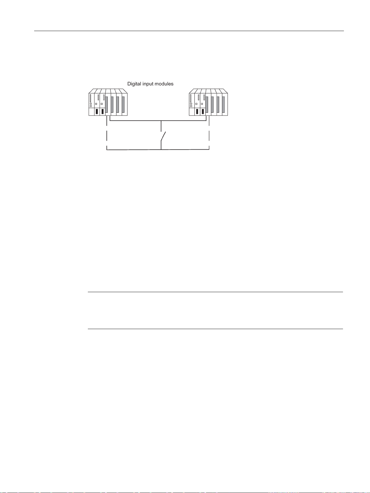
I/O configuration variants
Using redundant digital input modules with non-redundant encoders
Note
Remember that the proximity switches (Beros) must provide the current for the channels of
both digital input modules. The technical specifications of the respective modules, however,
specify only the required current per input.
6.7 Connection of two-channel I/O to the PROFIBUS DP interface
With non-redundant encoders, you use digital input modules in a 1-out-of-2 configuration:
Figure 6-14 Fault-tolerant digital input module in 1-out-of-2 configuration with one encoder
The use of redundant digital input modules increases their availability.
Discrepancy analysis detects "Continuous 1" and "Continuous 0" errors of the digital input
modules. A "Continuous 1" error means the value 1 is applied permanently at the input; a
"Continuous 0" error means that the input is not energized. This can be caused, for example,
by a short-circuit to L+ or M.
The current flow over the chassis ground connection between the modules and the encoder
should be the minimum possible.
When connecting an encoder to several digital input modules, the redundant modules must
operate at the same reference potential.
If you want to replace a module during operation and are not using redundant encoders, you
will need to use decoupling diodes.
If you do not use terminal modules, see the interconnection examples in the Appendix
Connection examples for redundant I/Os (Page 391).
CPU 410 Process Automation/CPU 410 SMART
System Manual, 05/2017, A5E31622160-AC
89
Page 90
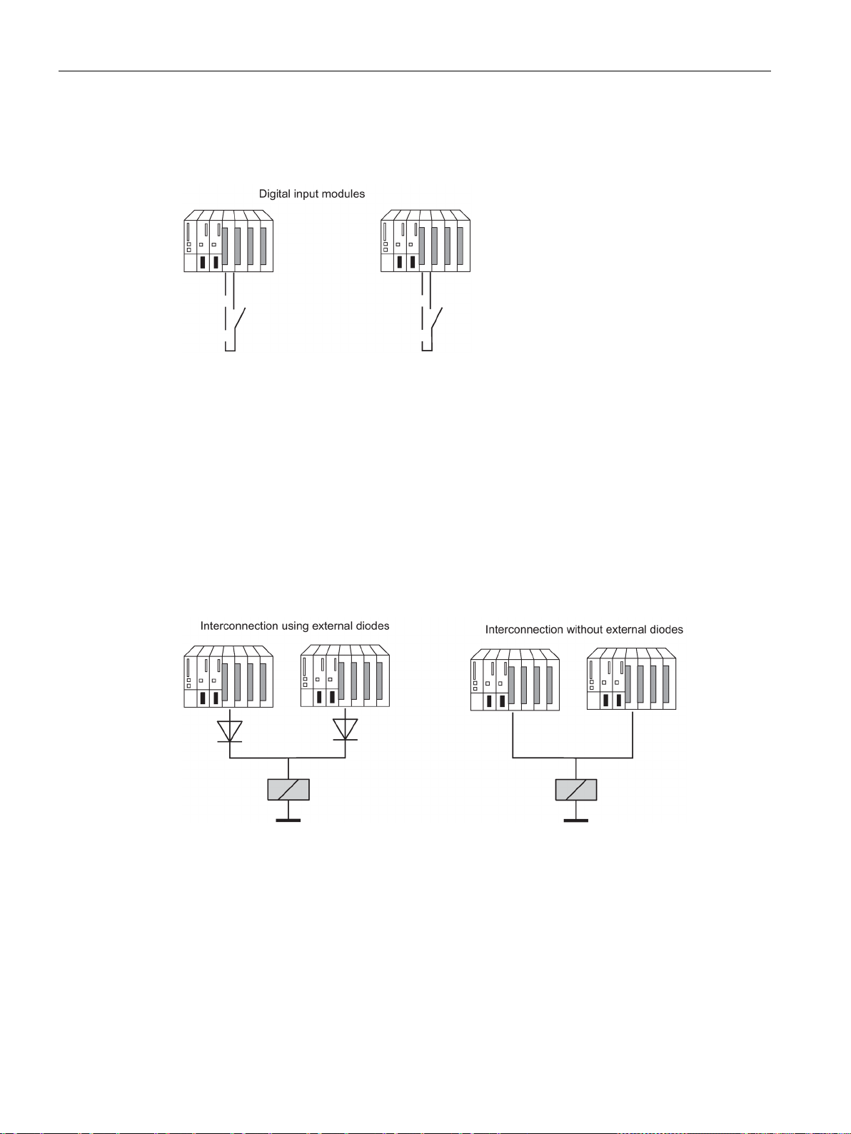
I/O configuration variants
Using redundant digital input modules with redundant encoders
Redundant digital output modules
6.7 Connection of two-channel I/O to the PROFIBUS DP interface
With redundant encoders, you use digital input modules in a 1-out-of-2 configuration:
Figure 6-15 Fault-tolerant digital input modules in 1-out-of-2 configuration with two encoders
The use of redundant encoders also increases their availability. A discrepancy analysis
detects all errors, except for the failure of a non-redundant load voltage supply. You can
enhance availability by installing redundant load power supplies.
You will find interconnection examples in Appendix Connection examples for redundant I/Os
(Page 391).
Fault-tolerant control of a final controlling element can be achieved by connecting two
outputs of two digital output modules or fail-safe digital output modules in parallel (1-out-of-2
configuration).
Figure 6-16 Fault-tolerant digital output modules in 1-out-of-2 configuration
The digital output modules must be connected to a common load voltage supply.
If you do not use terminal modules, see the interconnection examples in the Appendix
Connection examples for redundant I/Os (Page 391).
CPU 410 Process Automation/CPU 410 SMART
90 System Manual, 05/2017, A5E31622160-AC
Page 91

I/O configuration variants
Using analog input modules as redundant I/O
Note
The time that the system actually needs to determine a discrepancy de
factors: Bus runtimes, cycle times and call times of the user program, conversion times, etc.
For this reason, it is possible for redundant input signals to be different for longer than the
configured discrepancy time.
Note
There is no
underflow with 16#8000. The relevant channel is passivated immediately.
You should therefore disable all unused inputs in HW Config using the "Measurement type"
parameter.
6.7 Connection of two-channel I/O to the PROFIBUS DP interface
You specified the following parameters when you configured the analog input modules for
redundant operation:
● Tolerance window (configured as a percentage of the end value of the measuring range)
Two analog values are considered equal if they are within the tolerance window.
● Discrepancy time (maximum permitted time in which the redundant input signals can be
outside the tolerance window). The specified discrepancy time must be a multiple of the
update time of the process image and therefore also the basic conversion time of the
channels.
An error is generated when there is an input value discrepancy after the configured
discrepancy time has expired.
If you connect identical sensors to both analog input modules, the default value for the
discrepancy time is usually sufficient. If you use different sensors, in particular
temperature sensors, you will have to increase the discrepancy time.
● Applied value
The applied value represents the value of the two analog input values that is applied to
the user program.
The system verifies that the two read-in analog values are within the configured tolerance
window. If they are, the applied value is written to the lower data memory area of the process
input image. If there is a discrepancy and it is the first, it is marked accordingly and the
discrepancy time is started.
When the discrepancy time is running, the most recent valid value is written to the process
image of the module with the lower address and made available to the current process. If the
discrepancy time expires, the channel with the configured standard value is declared as valid
and the other channel is passivated. If the maximum value from both modules is configured
as the standard value, this value is then taken for further program execution and the other
channel is passivated. If the minimum value is set, this channel supplies the data to the
process and the channel with the maximum value is passivated. Whichever is the case, the
passivated channels are entered in the diagnostic buffer.
If the discrepancy is eliminated within the discrepancy time, analysis of the redundant input
signals is still carried out.
pends on various
discrepancy analysis when a channel reports an overflow with 16#7FFF or an
CPU 410 Process Automation/CPU 410 SMART
System Manual, 05/2017, A5E31622160-AC
91
Page 92
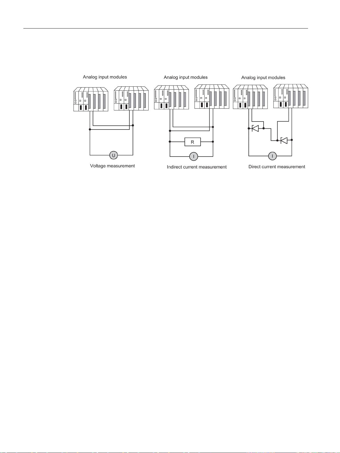
I/O configuration variants
Redundant analog input modules with non-redundant encoder
Redundant analog input modules for indirect current measurement
6.7 Connection of two-channel I/O to the PROFIBUS DP interface
With non-redundant encoders, analog input modules are used in a 1-out-of-2 configuration:
Figure 6-17 Fault-tolerant analog input modules in 1-out-of-2 configuration with one encoder
Remember the following when connecting an encoder to multiple analog input modules:
● Connect the analog input modules in parallel for voltage sensors (left in figure).
● You can convert a current into voltage using an external load to be able to use voltage
analog input modules connected in parallel (center in the figure).
● 2-wire transmitters are powered externally to allow you to repair the module online.
The redundancy of the fail-safe analog input modules enhances their availability.
If you do not use terminal modules, see the interconnection examples in the Appendix
Connection examples for redundant I/Os (Page 391).
The following applies to the wiring of analog input modules:
● Suitable encoders for this circuit are active transmitters with voltage output and
thermocouples.
● The "wire break" diagnostics function in HW Config must not be enabled either the
modules are operated with transmitters or when thermocouples are connected.
● Suitable encoder types: active 4-wire and passive 2-wire transmitters with output ranges
+/-20 mA, 0 to 20 mA, and 4 to 20 mA. 2-wire transmitters are powered by an external
auxiliary voltage.
● Criteria for the selection of resistance and input voltage range are the measurement
accuracy, number format, maximum resolution and possible diagnostics.
● In addition to the options listed, other input resistance and voltage combinations
according to Ohm’s law are also possible. However, note that the number format,
diagnostic capability and resolution may then be lost. The measurement error also
depends largely on the size of the measure resistance of certain modules.
● Use a measure resistance with a tolerance of +/- 0.1% and TC 15 ppm.
CPU 410 Process Automation/CPU 410 SMART
92 System Manual, 05/2017, A5E31622160-AC
Page 93

I/O configuration variants
Additional conditions for specific modules
Resistor
50 ohms
250 ohms
Current measuring range
+/-20 mA
+/-20 mA *)
4...20 mA
Measuring range cube position
"A"
"B"
Resolution
12 bits + sign
12 bits + sign
12 bits
S7 number format
x
x
- 1 input
"Wire break" diagnostics
- - x *)
Load for 4-wire transmitters
50 ohms
250 ohms
Input voltage for 2-wire transmitters
> 1.2 V
> 6 V
*) The AI 8x12bit outputs diagnostic interrupt and measured value "7FFF" in the event of wire break.
Resistor
250 ohms *)
Current measuring range
+/-20 mA
4...20 mA
Input range to be assigned
+/-5 V
1...5 V
Resolution
15 bits + sign
15 bits
S7 number format
x
- 1 input
"Wire break" diagnostics
-
x
Load for 4-wire transmitters
250 ohms
Input voltage for 2-wire transmitters
> 6 V
6.7 Connection of two-channel I/O to the PROFIBUS DP interface
AI 8x12 bit 6ES7 331-7K..02-0AB0
● Use a 50 ohm or 250 ohm resistor to map the current on a voltage:
Input range to be assigned +/-1 V +/-5 V 1...5 V
Circuit-specific measuring error
- 2 parallel inputs
-
-
0.5%
0.25%
The listed measuring error results solely from the interconnection of one or two voltage
inputs with a measure resistance. Allowance has neither been made here for the tolerance
nor for the basic/operational limits of the modules.
The measuring error for one or two inputs shows the difference in the measurement result
depending on whether two inputs or, in case of error, only one input acquires the current of
the transmitter.
AI 8x16 bit 6ES7 331-7NF00-0AB0
● Use a 250 ohm resistor to map the current on a voltage:
Circuit-specific measuring error
- 2 parallel inputs
*) It may be possible to use the freely connectible internal module 250 ohm resistors
CPU 410 Process Automation/CPU 410 SMART
System Manual, 05/2017, A5E31622160-AC
-
-
93
Page 94
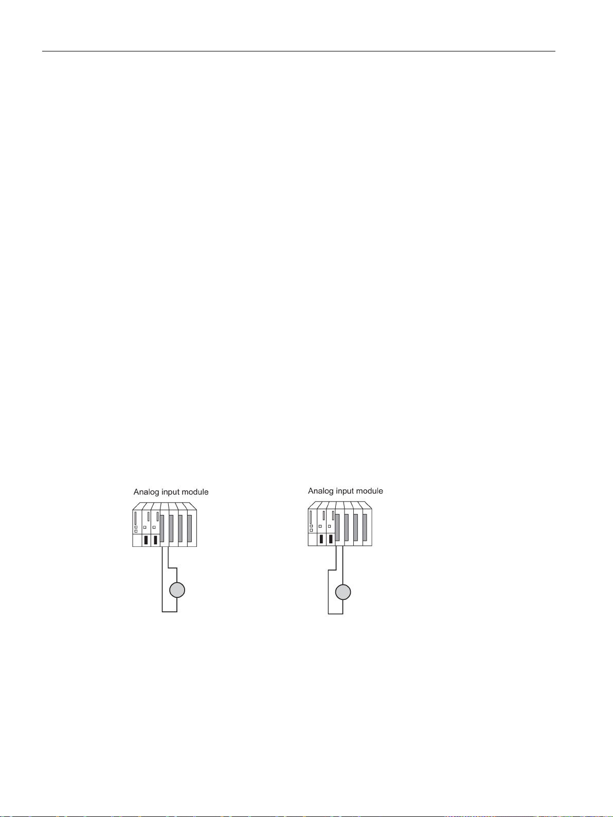
I/O configuration variants
Redundant analog input modules for direct current measurement
Redundant analog input modules with redundant encoders
6.7 Connection of two-channel I/O to the PROFIBUS DP interface
The following applies for wiring analog input modules:
● Suitable encoder types: active 4-wire and passive 2-wire transmitters with output ranges
+/-20 mA, 0 to 20 mA, and 4 to 20 mA. 2-wire transmitters are powered by an external
auxiliary voltage.
● The "wire break" diagnostics function supports only the 4...20 mA input range. All other
unipolar or bipolar ranges are excluded in this case.
● Suitable diodes include the types of the BZX85 or 1N47..A series (1.3 W Zener diodes)
with the voltages specified for the modules. When selecting other elements, make sure
that the reverse current is as low as possible.
● A fundamental measuring error of max. 1 µA results from this type of circuit and the
specified diodes due to the reverse current. In the 20 mA range and at a resolution of
16 bits, this value leads to an error of < 2 bits. Individual analog inputs in the circuit above
lead to an additional error, which may be listed in the constraints. The errors specified in
the manual must be added to these errors for all modules.
● The 4-wire transmitters used must be capable of driving the load resulting from the circuit
above. You will find details in the technical specifications of the individual modules.
● When connecting 2-wire transmitters, please note that the Zener diode circuit weighs
heavily in the power budget of the transmitter. The required input voltages are therefore
included in the technical specifications of the individual modules. Together with the
inherent supply specified on the transmitter data sheet, the minimum supply voltage is
calculated to L+ > U
e-2w
+ U
IS-TR
With double-redundant encoders, it is better to use fail-safe analog input modules in a 1-outof-2 configuration:
Figure 6-18 Fault-tolerant analog input modules in 1-out-of-2 configuration with two encoders
The use of redundant encoders also increases their availability.
A discrepancy analysis also detects external errors, except for the failure of a non-redundant
load voltage supply.
You will find interconnection examples in Appendix Connection examples for redundant I/Os
(Page 391).
The general comments made at the beginning of this documentation apply.
CPU 410 Process Automation/CPU 410 SMART
94 System Manual, 05/2017, A5E31622160-AC
Page 95
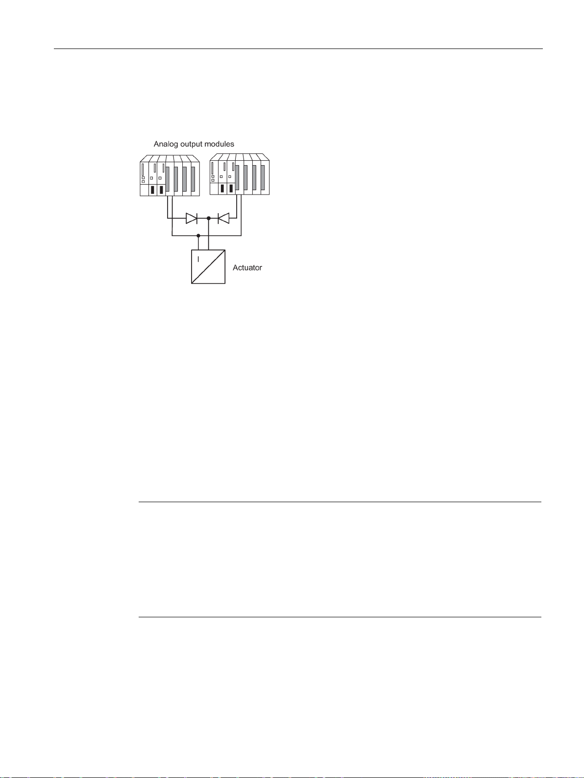
I/O configuration variants
Redundant analog output modules
Analog output signals
Note
The output value drops briefly to half, and after
the proper value. The duration of the output value drop is determined by the following time
intervals:
•
•
•
6.7 Connection of two-channel I/O to the PROFIBUS DP interface
You implement fault-tolerant control of a final controlling element by wiring two outputs of two
analog output modules in parallel (1-out-of-2 configuration)
Figure 6-19 Fault-tolerant analog output modules in 1-out-of-2 configuration
The following applies to the wiring of analog output modules:
● Wire the ground connections in a star structure to avoid output errors (limited common-
mode suppression of the analog output module).
If you do not use terminal modules, see the interconnection examples in the Appendix
Connection examples for redundant I/Os (Page 391)
Only analog output modules with current outputs (0 to 20 mA, 4 to 20 mA) can be operated
redundantly.
The output value is divided by 2, and each of the two modules outputs half. If one of the
modules fails, the failure is detected and the remaining module outputs the full value. As a
result, the surge at the output module in the event of an error is not as high.
Time interval between the initial occurrence of an interrupt and the interrupt report
reaching the CPU.
Time interval until the next RED_OUT (FB 451) call.
Time interval until the intact analog output module has doubled the output value.
the reaction in the program it is returned to
In the case of passivation or a CPU STOP, redundant analog outputs output an assignable
minimum current of approximately 120-1000 μA per module (or 240-1000 μA for HART
analog output modules), i.e., a total of approximately 240-2000 µA (or 480-2000 μA for
HART analog output modules). Considering the tolerance, this means that the output value
is always positive.
CPU 410 Process Automation/CPU 410 SMART
System Manual, 05/2017, A5E31622160-AC
95
Page 96

I/O configuration variants
Note
If both channels of a channel pair were passivated (e.g., by OB 85), the respective half of the
current value is still output to both storage locations in the process image of outputs. If one
channel is depassivated, then the full value is output on the available channel. If this is not
required, a substitute value must be writte
executing FB 451 "RED_OUT".
Depassivation of modules
Note
When a redundant module is assigned a process image partition and the corresponding OB
is not available on the CPU, the complete passivation process may take approximately 1
minute.
See also
6.7 Connection of two-channel I/O to the PROFIBUS DP interface
A configured substitute value of 0 mA will produce at least these output values. In a
redundant configuration of analog outputs, the substitute value of the current outputs is
automatically set permanently to "zero current and zero voltage". You can also specify a
configurable compensation current of 0-400 µA for an output range of 4-20 mA.
This means you have the option of matching the minimum/compensation current to the
connected I/O.
To minimize the error of the total current at the summing point in case of one-sided
passivation, the assigned compensation current is subtracted in this case from the current of
the depassivated (i.e., active) channel with a pre-set value of 4 mA (range +-20 µA).
n to the lower channels of both modules prior to
Passivated modules are depassivated by the following events:
● When the fault-tolerant system starts up
● When the fault-tolerant system switched to "redundant" mode
● After system modifications during operation
● If you call FC 451 "RED_DEPA" and at least one redundant channel or module is
passivated.
The depassivation is executed in FB 450 "RED IN" after one of these events has occurred.
Completion of the depassivation of all modules is logged in the diagnostics buffer.
SIMATIC Process Control System PCS 7 Released Modules
(https://support.industry.siemens.com/cs/ww/de/view/109736547/en)
S7-400H Systems Redundant I/O
(http://support.automation.siemens.com/WW/view/en/9275191)
CPU 410 Process Automation/CPU 410 SMART
96 System Manual, 05/2017, A5E31622160-AC
Page 97

I/O configuration variants
6.7.3
Evaluating the passivation status
Procedure
Evaluating the passivation status using the status byte
Evaluating the passivation status of individual module pairs by means of MODUL_STATUS_WORD
6.8
Media redundancy
Note
Support of PRP (Parallel Redundancy Protocol) or MRPD (Media Redundancy Protocol
Domain) does not equal MRP functionality or vice versa.
6.8 Media redundancy
First, determine the passivation status by evaluating the status byte in the status/control
word "FB_RED_IN.STATUS_CONTROL_W". If you see that one or more modules have
been passivated, determine the status of the respective module pairs in
MODUL_STATUS_WORD.
The status word "FB_RED_IN.STATUS_CONTROL_W" is located in the instance DB of FB
450 "RED_IN". The status byte returns information on the status of the redundant I/Os. The
assignment of the status byte is described in the online help for the respective block library.
MODUL_STATUS_WORD is an output parameter of FB 453 and can be interconnected
accordingly. It returns information on the status of individual module pairs.
The assignment of the MODUL_STATUS_WORD status byte is described in the online help
for the respective function block library.
Media redundancy is a function for ensuring network availability and thus contributes to
increasing the plant availability. Redundant transmission links in a ring topology ensure that
an alternative communication path is always available if a transmission link fails. Following a
fault in one transmission link, data traffic can resume over the alternative link after a
maximum reconfiguration time of 200 ms.
For the components involved, you can enable the media redundancy protocol (MRP) in HW
Config. The components (IO devices, switches) must support MRP. MRP is a component of
the PROFINET IO standardization according to IEC 61158.
In the case of media redundancy with MRP, one device is specified as the media
redundancy manager (MRM) in HW Config. All other devices are redundancy clients.
CPU 410 Process Automation/CPU 410 SMART
System Manual, 05/2017, A5E31622160-AC
97
Page 98
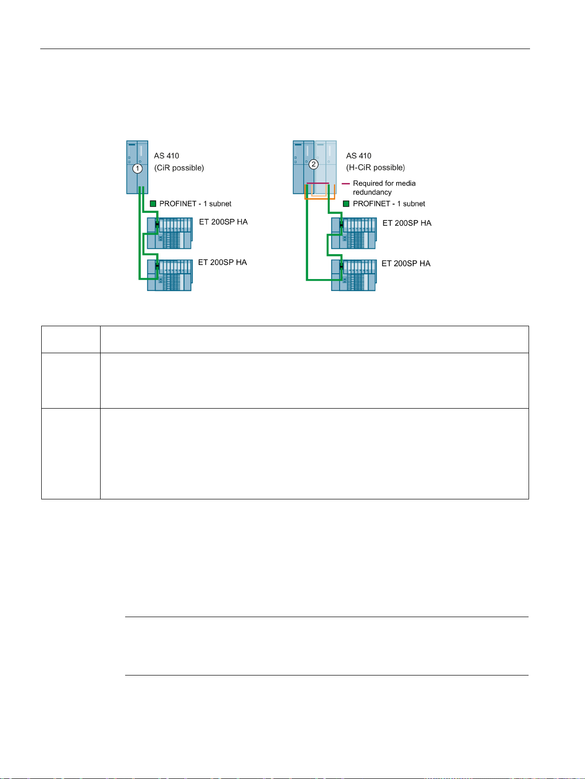
I/O configuration variants
Configuration
Configuration
Properties
The nodes connected to PROFINET IO must be assigned unique names.
The nodes on the fieldbus (PROFINET IO) must be assigned unique names.
Installing a ring topology
Note
The real
the ring exceeds the selected watc
whose IO data is transmitted over a ring.
6.8 Media redundancy
The following figure shows examples of the connection of IO devices to the PROFINET IO
system:
①
②
Media redundancy
Each node is connected to two other nodes in a ring configuration.
The IO controller must be configured as an MRP manager in HW Config.
Media redundancy + system redundancy
The PROFINET IO system begins and ends at one IO controller each in this example.
Each node is connected to two other nodes in a ring configuration.
The MRP parameter assignment must be complete. If a PROFINET IO system is created at each PN IO
connection of the CPU, a newly inserted interface module is automatically connected to the PROFINET IO
system of the CPU.
To set up a ring topology with media redundancy, you must join both free ends of a line
network topology in the same device. You join the line topology to form a ring via two ports
(ring ports, port ID "R") of a device connected to the ring.
The data paths between the individual devices are automatically reconfigured if the ring is
interrupted at any point. The devices are available again after reconfiguration.
-time communication is interrupted (station failure) when the reconfiguration time of
hdog time of the IO devices. This applies to all IO devices
CPU 410 Process Automation/CPU 410 SMART
98 System Manual, 05/2017, A5E31622160-AC
Page 99

I/O configuration variants
Note
Before physically joining the ring together, download the configuration of your project to the
individual devices.
Topology
Additional information
6.8 Media redundancy
You can also combine media redundancy under PROFINET IO with other PROFINET IO
functions.
For additional information, refer to the STEP 7 Online Help and to Manual PROFINET
System Description (http://support.automation.siemens.com/WW/view/en/19292127).
CPU 410 Process Automation/CPU 410 SMART
System Manual, 05/2017, A5E31622160-AC
99
Page 100

I/O configuration variants
6.8 Media redundancy
CPU 410 Process Automation/CPU 410 SMART
100 System Manual, 05/2017, A5E31622160-AC
 Loading...