

Siemens SIMATIC CPU 1515SP PC2 F, SIMATIC CPU 1515SP PC2 T, SIMATIC CPU 1515SP PC2 TF User Manual
Page 1
Page 2

___________________
___________________
___________________
___________________
___________________
___________________
___________________
___________________
___________________
___________________
___________________
___________________
___________________
___________________
___________________
___________________
SIMATIC
ET 200SP Open Controller
CPU 1515SP PC2 (F/T/TF)
Operating Instructions
09/2018
A5E42603425
Introduction
1
Safety information
2
Areas of application
3
Product overview
4
Application planning
5
Installation
6
Wiring
7
Commissioning
8
Interrupt, error and system
messages
9
Functions
10
Maintenance
11
Technical specifications
12
Dimension drawings
13
Spare parts/accessories
14
Appendix
A
List of abbreviations
B
-AA
Page 3
Siemens AG
Division Digital Factory
Postfach 48 48
90026 NÜRNBERG
GERMANY
A5E42603425-AA
Ⓟ
Copyright © Siemens AG 2018.
All rights reserved
Legal information
Warning notice system
DANGER
indicates that death or severe personal injury will result if proper precautions are not taken.
WARNING
indicates that death or severe personal injury may result if proper precautions are not taken.
CAUTION
indicates that minor personal injury can result if proper precautions are not taken.
NOTICE
indicates that property damage can result if proper precautions are not taken.
Qualified Personnel
personnel qualified
Proper use of Siemens products
WARNING
Siemens products may only be used for the applications described in the catalog and in the relevant technical
ambient conditions must be complied with. The information in the relevant documentation must be observed.
Trademarks
Disclaimer of Liability
This manual contains notices you have to observe in order to ensure your personal safety, as well as to prevent
damage to property. The notices referring to your personal safety are highlighted in the manual by a safety alert
symbol, notices referring only to property damage have no safety alert symbol. These notices shown below are
graded according to the degree of danger.
If more than one degree of danger is present, the warning notice representing the highest degree of danger will
be used. A notice warning of injury to persons with a safety alert symbol may also include a warning relating to
property damage.
The product/system described in this documentation may be operated only by
task in accordance with the relevant documentation, in particular its warning notices and safety instructions.
Qualified personnel are those who, based on their training and experience, are capable of identifying risks and
avoiding potential hazards when working with these products/systems.
Note the following:
documentation. If products and components from other manufacturers are used, these must be recommended
or approved by Siemens. Proper transport, storage, installation, assembly, commissioning, operation and
maintenance are required to ensure that the products operate safely and without any problems. The permissible
All names identified by ® are registered trademarks of Siemens AG. The remaining trademarks in this publication
may be trademarks whose use by third parties for their own purposes could violate the rights of the owner.
We have reviewed the contents of this publication to ensure consistency with the hardware and software
described. Since variance cannot be precluded entirely, we cannot guarantee full consistency. However, the
information in this publication is reviewed regularly and any necessary corrections are included in subsequent
editions.
for the specific
07/2018 Subject to change
Page 4

Table of contents
1 Introduction ............................................................................................................................................. 6
2 Safety information ................................................................................................................................. 13
3 Areas of application .............................................................................................................................. 17
4 Product overview .................................................................................................................................. 18
5 Application planning .............................................................................................................................. 28
6 Installation ............................................................................................................................................ 34
7 Wiring ................................................................................................................................................... 36
1.1 Documentation on CPU 1515SP PC2 ...................................................................................... 8
1.2 Information about third-party software updates ...................................................................... 12
1.3 Notes on protecting administrator accounts ........................................................................... 12
2.1 Security information ................................................................................................................ 13
2.2 General safety instructions ..................................................................................................... 14
2.3 Notes on use ........................................................................................................................... 16
3.1 Areas of application of fail-safe CPUs .................................................................................... 17
3.2 Areas of application of technology CPUs ............................................................................... 17
4.1 Field of application .................................................................................................................. 18
4.2 Characteristics ........................................................................................................................ 19
4.3 Sample configuration .............................................................................................................. 20
4.4 Components ............................................................................................................................ 22
4.5 Operator controls and connection elements ........................................................................... 24
4.6 Scope of delivery .................................................................................................................... 27
5.1 Basics...................................................................................................................................... 28
5.2 Unpacking the device.............................................................................................................. 29
5.3 Identification data .................................................................................................................... 30
5.4 Installation location ................................................................................................................. 31
5.5 Hardware configuration ........................................................................................................... 33
6.1 Installing the device ................................................................................................................ 34
7.1 Notes on connection ............................................................................................................... 36
7.2 Terminal and block diagram ................................................................................................... 37
7.3 Electrical configuration ............................................................................................................ 38
7.4 Connecting devices to networks ............................................................................................. 40
CPU 1515SP PC2 (F/T/TF)
Operating Instructions, 09/2018, A5E42603425-AA
3
Page 5

Table of contents
8 Commissioning ..................................................................................................................................... 42
9 Interrupt, error and system messages ................................................................................................... 51
10 Functions .............................................................................................................................................. 54
11 Maintenance ......................................................................................................................................... 58
12 Technical specifications ........................................................................................................................ 66
7.5 Securing cables...................................................................................................................... 41
8.1 Notes on commissioning ........................................................................................................ 42
8.2 Basic commissioning procedure ............................................................................................ 43
8.2.1 Requirements ......................................................................................................................... 43
8.2.2 Preparing commissioning ....................................................................................................... 43
8.2.3 Commissioning procedure ..................................................................................................... 43
8.3 Initial commissioning an open controller ................................................................................ 45
8.3.1 Creating the configuration of the Open Controller ................................................................. 45
8.3.2 Setting the IP address ............................................................................................................ 46
8.3.3 Changing the properties of the S7-1500 Software Controller ................................................ 46
8.3.4 Establishing the HMI connection............................................................................................ 47
8.3.5 Downloading a project to the target system ........................................................................... 47
8.3.6 Transferring license keys ....................................................................................................... 48
8.3.7 Switching the Open Controller on/off ..................................................................................... 50
9.1 Status and error display ......................................................................................................... 51
10.1 Monitoring functions ............................................................................................................... 54
10.1.1 Requirements ......................................................................................................................... 54
10.1.2 Temperature monitoring ......................................................................................................... 55
10.1.3 Monitoring drives .................................................................................................................... 55
10.1.4 Operating hours counter ........................................................................................................ 55
10.2 Retentive memory NVRAM .................................................................................................... 55
10.3 BIOS setup ............................................................................................................................. 56
10.4 Power options ........................................................................................................................ 56
10.5 "Unified Write Filter (UWF)" write filter ................................................................................... 57
11.1 Backing up and restoring data ............................................................................................... 58
11.2 Partitions in the delivery state ................................................................................................ 59
11.3 Restoring the delivery state ................................................................................................... 60
11.4 Updating software .................................................................................................................. 62
11.5 Windows 10 IoT Enterprise (64-bit) ....................................................................................... 62
11.6 Sending the device to customer service ................................................................................ 63
11.7 Removing and inserting the CFast card ................................................................................ 64
11.8 Recycling and disposal .......................................................................................................... 65
12.1 Standards and approvals ....................................................................................................... 66
12.2 Electromagnetic compatibility ................................................................................................ 71
12.3 Shipping and storage conditions ............................................................................................ 73
CPU 1515SP PC2 (F/T/TF)
4 Operating Instructions, 09/2018, A5E42603425-AA
Page 6

Table of contents
13 Dimension drawings ............................................................................................................................ 121
14 Spare parts/accessories ...................................................................................................................... 123
A Appendix............................................................................................................................................. 124
B List of abbreviations ............................................................................................................................ 126
Glossary ............................................................................................................................................. 128
Index................................................................................................................................................... 131
12.4 Mechanical and climatic ambient conditions .......................................................................... 74
12.5 Information on insulation, protection class, degree of protection and rated voltage .............. 76
12.6 Use of the ET 200SP in zone 2 potentially explosive atmospheres ....................................... 77
12.7 Module data ............................................................................................................................ 78
12.7.1 Technical specifications of CPU 1515SP PC2 - basic device ................................................ 78
12.7.2 Technical specifications CPU 1515SP PC2 ........................................................................... 81
12.7.3 Technical specifications of CPU 1515SP PC2 + HMI 128PT ................................................. 85
12.7.4 Technical specifications of CPU 1515SP PC2 + HMI 512PT ................................................. 89
12.7.5 Technical specifications of CPU 1515SP PC2 + HMI 2048PT ............................................... 93
12.7.6 Technical specifications of CPU 1515SP PC2 F .................................................................... 97
12.7.7 Technical specifications of CPU 1515SP PC2 F + HMI 128PT ............................................ 101
12.7.8 Technical specifications of CPU 1515SP PC2 F + HMI 512PT ............................................ 105
12.7.9 Technical specifications of CPU 1515SP PC2 F + HMI 2018PT .......................................... 109
12.7.10 Technical specifications of CPU 1515SP PC2 T .................................................................. 113
12.7.11 Technical specifications of CPU 1515SP PC2 TF ................................................................ 117
12.7.12 S7-1500 Software Controller CPU 1505SP (F/T/TF) ............................................................ 120
13.1 CPU 1515SP PC2 ................................................................................................................. 121
14.1 Accessories/spare parts........................................................................................................ 123
A.1 Siemens Industry Online Support ......................................................................................... 124
A.2 Industry Mall .......................................................................................................................... 124
A.3 Troubleshooting .................................................................................................................... 125
B.1 Abbreviations ........................................................................................................................ 126
CPU 1515SP PC2 (F/T/TF)
Operating Instructions, 09/2018, A5E42603425-AA
5
Page 7

1
Purpose of the documentation
Basic knowledge required
These operating instructions supplement the system manual
ET 200SP distributed I/O system. Functions that generally relate to the system are described
in this manual.
The information provided in these operating instructions and in the system/function manuals
supports you in commissioning the CPU 1515SP PC2.
The system must be operated and used by qualified staff only.
The following knowledge is required:
● Installation guideline for SIMATIC ET 200SP
● Totally Integrated Automation Portal, in particular:
– Hardware configuration with
– Communication between CPUs
● PC based automation with an S7-1500 software controller and with
WinCC Runtime Advanced
● Basic knowledge of fail-safe automation systems
● Basic knowledge of PC technology
● Windows 10 IoT Enterprise operating system (64-bit)
hardware and network editor
CPU 1515SP PC2 (F/T/TF)
6 Operating Instructions, 09/2018, A5E42603425-AA
Page 8

Introduction
Conventions
only
only
only
Note
A note contains important information on the product described in the documentation, on the
handling of the product or on the section of the documentation to which particular attention
should be paid.
Scope of validity of the documentation
ET 200SP Open Controller
Article number
Standard CPU
Fail-safe CPUs
Technology CPUs
Fail-safe technology CPUs
1.1 Documentation on CPU 1515SP PC2
STEP 7: In this documentation, "STEP 7" is used as a synonym for all versions of the
configuration and programming software "STEP 7 (TIA Portal)".
"CPU1515SP PC2 T" means that the respective section applies
"CPU 1515SP PC2 T".
"CPU1515SP PC2 F" means that the respective section applies
"CPU 1515SP PC2 F".
"CPU1515SP PC2 TF" means that the respective section applies
"CPU 1515SP PC2 TF".
"CPU 1515SP PC2" also includes "CPU1 515SP PC2 F", "CPU 1515SP PC2 T" and
"CPU 1515SP PC2 TF".
Please also observe notes marked as follows:
This documentation is valid for the following products:
to the
to the
to the
• CPU 1515SP PC2 basic device
• CPU 1515SP PC2
• CPU 1515SP PC2 + HMI 128PT
• CPU 1515SP PC2 + HMI 512PT
• CPU 1515SP PC2 + HMI 2048PT
• CPU 1515SP PC2 F
• CPU 1515SP PC2 F + HMI 128PT
• CPU 1515SP PC2 F + HMI 512PT
• CPU 1515SP PC2 F + HMI 2048PT
• CPU 1515SP PC2 T
• CPU 1515SP PC2 TF
6ES7677-2DB40-0AA0
6ES7677-2DB42-0GB0
6ES7677-2DB42-0GK0
6ES7677-2DB42-0GL0
6ES7677-2DB42-0GM0
6ES7677-2SB42-0GB0
6ES7677-2SB42-0GK0
6ES7677-2SB42-0GL0
6ES7677-2SB42-0GM0
6ES7677-2VB42-0GB0
6ES7677-2WB42-0GB0
CPU 1515SP PC2 (F/T/TF)
Operating Instructions, 09/2018, A5E42603425-AA
7
Page 9
Introduction
1.1
Documentation on CPU 1515SP PC2
1.1 Documentation on CPU 1515SP PC2
The following additional documentation is required to use the CPU 1515SP PC2:
● Operating instructions CPU 1505SP (F/T/TF), CPU 1507S (F) Version 2.5
(http://support.automation.siemens.com/WW/view/en/109740725
● STEP 7 and WinCC Engineering V15 system manual
(https://support.industry.siemens.com/cs/ww/en/view/109755202
● ET 200SP distributed I/O system manual
(http://support.automation.siemens.com/WW/view/en/58649293
● ET 200SP server module manual
(http://support.automation.siemens.com/WW/view/en/63257531
● SIMATIC Safety - Configuring and Programming
(http://support.automation.siemens.com/WW/view/en/54110126
● SIMATIC S7-1200/S7-1500 F-CPUs
(http://support.automation.siemens.com/WW/view/en/109478599
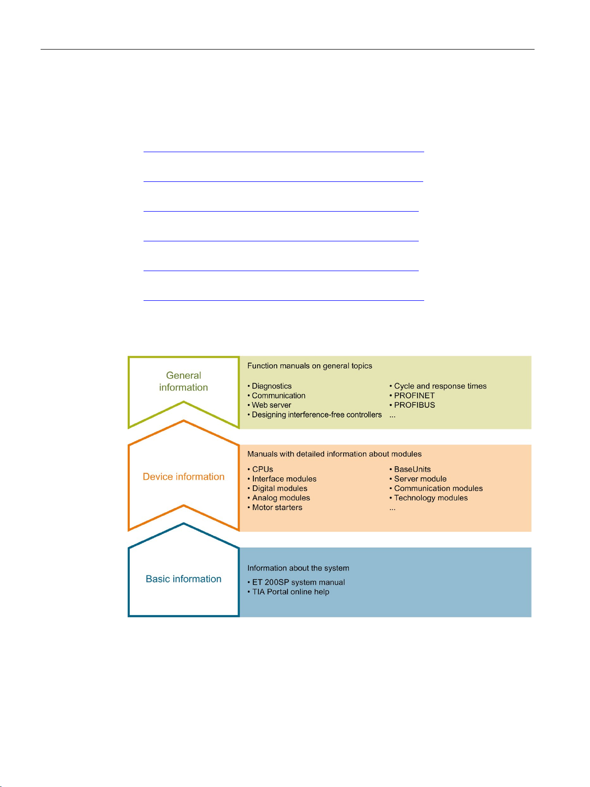
The documentation for the SIMATIC ET 200SP distributed I/O system is arranged into three
areas.
This arrangement enables you to access the specific content you require.
)
)
)
)
)
)
CPU 1515SP PC2 (F/T/TF)
8 Operating Instructions, 09/2018, A5E42603425-AA
Page 10

Introduction
Basic information
Device information
General information
Manual Collection ET 200SP
"mySupport"
"mySupport" - Documentation
1.1 Documentation on CPU 1515SP PC2
The system manual describes in detail the configuration, installation, wiring and
commissioning of the SIMATIC ET 200SP. distributed I/O system. The STEP 7 online help
supports you in the configuration and programming.
Product manuals contain a compact description of the module-specific information, such as
properties, wiring diagrams, characteristics and technical specifications.
The function manuals contain detailed descriptions on general topics regarding the SIMATIC
ET 200SP distributed I/O system, e.g. diagnostics, communication, Web server, motion
control and OPC UA.
You can download the documentation free of charge from the Internet
http://w3.siemens.com/mcms/industrial-automation-systems-simatic/en/manual-
(
overview/tech-doc-et200/Pages/Default.aspx).
Changes and supplements to the manuals are documented in a Product Information.
You can download the product information free of charge from the Internet
(https://support.industry.siemens.com/cs/us/en/view/73021864
The Manual Collection contains the complete documentation on the SIMATIC ET 200SP
distributed I/O system gathered together in one file.
You can find the Manual Collection on the Internet
(http://support.automation.siemens.com/WW/view/en/84133942
With "mySupport", your personal workspace, you make the most of your Industry Online
Support.
In "mySupport" you can store filters, favorites and tags, request CAx data and put together
your personal library in the Documentation area. Furthermore, your data is automatically
filled into support requests and you always have an overview of your current requests.
You need to register once to use the full functionality of "mySupport".
You can find "mySupport" in the Internet (https://support.industry.siemens.com/My/ww/en
).
).
).
In the Documentation area of "mySupport", you have the possibility to combine complete
manuals or parts of them to make your own manual.
You can export the manual in PDF format or in an editable format.
You can find "mySupport" - Documentation in the Internet
(http://support.industry.siemens.com/My/ww/en/documentation
CPU 1515SP PC2 (F/T/TF)
Operating Instructions, 09/2018, A5E42603425-AA
).
9
Page 11

Introduction
"mySupport" - CAx Data
Application examples
TIA Selection Tool
1.1 Documentation on CPU 1515SP PC2
In the CAx Data area of "mySupport", you can have access the latest product data for your
CAx or CAe system.
You configure your own download package with a few clicks.
In doing so you can select:
● Product images, 2D dimension drawings, 3D models, internal circuit diagrams, EPLAN
macro files
● Manuals, characteristics, operating manuals, certificates
● Product master data
You can find "mySupport" - CAx Data in the Internet
(http://support.industry.siemens.com/my/ww/en/CAxOnline
).
The application examples support you with various tools and examples for solving your
automation tasks. Solutions are shown in interplay with multiple components in the system separated from the focus in individual products.
You can find the application examples on the Internet
(https://support.industry.siemens.com/sc/ww/en/sc/2054
With the TIA Selection Tool, you can select, configure and order devices for Totally
Integrated Automation (TIA).
This tool is the successor of the SIMATIC Selection Tool and combines the known
configurators for automation technology into one tool.
With the TIA Selection Tool, you can generate a complete order list from your product
selection or product configuration.
You can find the TIA Selection Tool on the Internet
(http://w3.siemens.com/mcms/topics/en/simatic/tia-selection-tool
).
).
CPU 1515SP PC2 (F/T/TF)
10 Operating Instructions, 09/2018, A5E42603425-AA
Page 12

Introduction
SIMATIC Automation Tool
PRONETA
1.1 Documentation on CPU 1515SP PC2
You can use the SIMATIC Automation Tool to run commissioning and maintenance activities
simultaneously on various SIMATIC S7 stations as a bulk operation independently of the
TIA Portal.
The SIMATIC Automation Tool provides a multitude of functions:
● Scanning of a PROFINET/Ethernet network and identification of all connected CPUs
● Address assignment (IP, subnet, gateway) and station name (PROFINET device) to a
CPU
● Transfer of the data and the programming device/PC time converted to UTC time to the
module
● Program download to CPU
● Operating mode switchover RUN/STOP
● Localization of the CPU by means of LED flashing
● Reading out CPU error information
● Reading the CPU diagnostic buffer
● Reset to factory settings
● Updating the firmware of the CPU and connected modules
You can find the SIMATIC Automation Tool on the Internet
(https://support.industry.siemens.com/cs/ww/en/view/98161300
).
With SIEMENS PRONETA (PROFINET network analysis), you analyze the plant network
during commissioning. PRONETA features two core functions:
● The topology overview independently scans PROFINET and all connected components.
● The IO check is a fast test of the wiring and the module configuration of a system.
You can find SIEMENS PRONETA on the Internet
(https://support.industry.siemens.com/cs/ww/en/view/67460624
).
CPU 1515SP PC2 (F/T/TF)
Operating Instructions, 09/2018, A5E42603425-AA
11
Page 13

Introduction
SINETPLAN
1.2
Information about third-party software updates
1.3
Notes on protecting administrator accounts
1.2 Information about third-party software updates
SINETPLAN, the Siemens Network Planner, supports you in planning automation systems
and networks based on PROFINET. The tool facilitates professional and predictive
dimensioning of your PROFINET installation as early as in the planning stage. In addition,
SINETPLAN supports you during network optimization and helps you to exploit network
resources optimally and to plan reserves. This helps to prevent problems in commissioning
or failures during productive operation even in advance of a planned operation. This
increases the availability of the production plant and helps improve operational safety.
The advantages at a glance
● Network optimization thanks to port-specific calculation of the network load
● Increased production availability thanks to online scan and verification of existing systems
● Transparency before commissioning through importing and simulation of existing STEP 7
projects
● Efficiency through securing existing investments in the long term and optimal exploitation
of resources
You can find SINETPLAN on the Internet.
This product contains third-party software. Siemens accepts liability with respect to
updates/patches for the third-party software only when these are distributed by Siemens in
the context of a Software Update Service contract or officially approved by Siemens.
Otherwise, updates/patches are installed at the user's own risk. You can find more
information about our software update service offer under
http://w3.siemens.com/mcms/topics/en/simatic/licenses/software-update-
(
service/Pages/Default.aspx).
A user with administrator rights has extensive access and manipulation possibilities.
Therefore, make sure that the administrator account is adequately protected to prevent
unauthorized changes. To do this, set secure passwords and use a standard user account
for regular operation. Other measures, such as the use of security policies, should be
applied as required.
CPU 1515SP PC2 (F/T/TF)
12 Operating Instructions, 09/2018, A5E42603425-AA
Page 14

2
2.1
Security information
Siemens provides products and solutions with industrial security functions that support the
secure operation of plants, systems, machines and networks.
In order to protect plants, systems, machines and networks against cyber threats, it is
necessary to implement – and continuously maintain – a holistic, state-of-the-art industrial
security concept. Siemens' products and solutions constitute one element of such a concept.
Customers are responsible for preventing unauthorized access to their plants, systems,
machines and networks. Such systems, machines and components should only be
connected to an enterprise network or the internet if and to the extent such a connection is
necessary and only when appropriate security measures (e.g. firewalls and/or network
segmentation) are in place.
For additional information on industrial security measures that may be implemented, please
visit (https://www.siemens.com/industrialsecurity
).
Siemens' products and solutions undergo continuous development to make them more
secure. Siemens strongly recommends that product updates are applied as soon as they are
available and that the latest product versions are used. Use of product versions that are no
longer supported, and failure to apply the latest updates may increase customers' exposure
to cyber threats.
To stay informed about product updates, subscribe to the Siemens Industrial Security RSS
Feed under (https://www.siemens.com/industrialsecurity
).
CPU 1515SP PC2 (F/T/TF)
Operating Instructions, 09/2018, A5E42603425-AA
13
Page 15
Safety information
2.2
General safety instructions
WARNING
Life-endangering voltage when control cabinet is open
Safe operation of a plant
NOTICE
Protective measures
PC2
Repairs
WARNING
Damage caused by opening the device
2.2 General safety instructions
If the device is installed in a control cabinet, areas or components can be under lifeendangering voltage when the control cabinet is open.
Contact with these areas or components may lead to death through electric shock.
Switch off the power before opening the control cabinet.
If the device is operated in a machine in accordance with the machinery directive, the
provisions of the guideline 2006/42/EC apply.
To ensure safe operation of a plant, you have to take suitable IT security measures, for
example, network segmentation.
Seal the cover to protect the CFast card with the operating system of the CPU 1515SP
from unauthorized access.
For more information on Industrial Security, refer to the Internet
(http://www.siemens.com/industrialsecurity
).
If you have questions about whether it is permissible to install the device in the planned
environment, please contact your service representative.
Unauthorized opening of and improper repairs to the device may result in substantial
damage to equipment or endanger the user.
Only authorized personnel are permitted to repair the device.
You can find more information on the repair in the section Sending device in for repair
(Page 63).
CPU 1515SP PC2 (F/T/TF)
14 Operating Instructions, 09/2018, A5E42603425-AA
Page 16

Safety information
ESD guidelines
2.2 General safety instructions
Modules containing electrostatic sensitive devices (ESDs) can be identified by the following
label:
Strictly follow the guidelines mentioned below when handling modules which are sensitive to
ESD:
● Before working with modules with ESD, you need to ensure that you are free of
electrostatic charge (e.g. by touching a grounded object).
● All devices and tools must be free of static charge.
● Always pull the mains connector and disconnect the battery before installing or removing
modules which are sensitive to ESD.
● Handle modules fitted with ESDs only by their edges.
● Do not touch any connector pins or conductors on modules containing ESDs.
CPU 1515SP PC2 (F/T/TF)
Operating Instructions, 09/2018, A5E42603425-AA
15
Page 17

Safety information
2.3
Notes on use
WARNING
Hazards at an unprotected machine or plant
NOTICE
Ambient conditions
2.3 Notes on use
According to the results of a risk analysis, hazards can occur at an unprotected machine.
The hazards may lead to personal injury.
According to the risk analysis, the risk of injury to persons can be countered with the
following measures:
• Additional protective equipment at the machine or plant. In this case, the programming,
parameter assignment and wiring of the I/O used, in particular, must be performed in
accordance with the safety criteria (SIL, PL or Cat.) ascertained by means of an
appropriate risk analysis.
• Use of the device for its intended purpose, which can be established by performing a
functional test on the plant. This allows errors in programming, parameter assignment
and wiring to be detected.
• Documentation of the test results which can be entered, if required, into the relevant
safety certificates.
Ambient conditions for which the device is not suitable can lead to faults or damage the
device.
Note the following:
• Only operate the device in enclosed areas. If you do not comply with this instruction, the
warranty becomes void.
• Only operate the device in accordance with the ambient conditions given in the technical
specifications.
• Protect the device from dust, moisture and heat.
• Do not expose the device to direct sunlight or other strong sources of light.
• The device must not be used in places with more difficult operating conditions through
corrosive vapors or gases without taking additional protective measures, for example,
supply of clean air.
CPU 1515SP PC2 (F/T/TF)
16 Operating Instructions, 09/2018, A5E42603425-AA
Page 18

3
3.1
Areas of application of fail-safe CPUs
Areas of application
Reference
3.2
Areas of application of technology CPUs
Areas of application
Reference
F-CPUs are mainly designed for personal and machine protection. In addition to the safety
program, you can also program standard applications. You can operate the F-CPUs in safety
mode or in standard mode.
Information on the use of F-CPUs in safety mode is available in the programming and
operating manual SIMATIC Safety - Configuring and Programming
(http://support.automation.siemens.com/WW/view/en/54110126
).
You can find information on using the CPU 1505SP (F) Software Controller in the associated
manual (https://support.industry.siemens.com/cs/ww/en/view/109740725
F-product information (https://support.industry.siemens.com/cs/ww/en/view/109478599).
Areas of application of T-CPUs are motion control applications such as gearing and
camming as well as control of kinematics. Due to the supported technology functions, the
S7-1500T CPUs are suitable for controlling packaging machines, converting applications,
assembly automation, etc.
You can operate the TF-CPUs in safety mode or in standard mode.
You can find information on using the T-CPUs in the function manual SIMATIC S7-1500T
Motion Control (http://support.automation.siemens.com/WW/view/en/109749263
You can find information on using the T-CPUs in the function manual SIMATIC S7-1500T
kinematics functions (http://support.automation.siemens.com/WW/view/en/109749264
) and in the
).
).
You can find information on using the F-CPUs and TF-CPUs in safety mode in the product
information for SIMATIC S7-1200/S7-1500 F-CPUs
(http://support.automation.siemens.com/WW/view/en/109478599
CPU 1515SP PC2 (F/T/TF)
Operating Instructions, 09/2018, A5E42603425-AA
).
17
Page 19
4
4.1
Field of application
Article number
View of the module
The article number depends on the pre-installed S7-1500 Software Controller and
HMI Runtime.
You can find an overview of the article numbers in the section Scope of validity of the
documentation (Page 6).
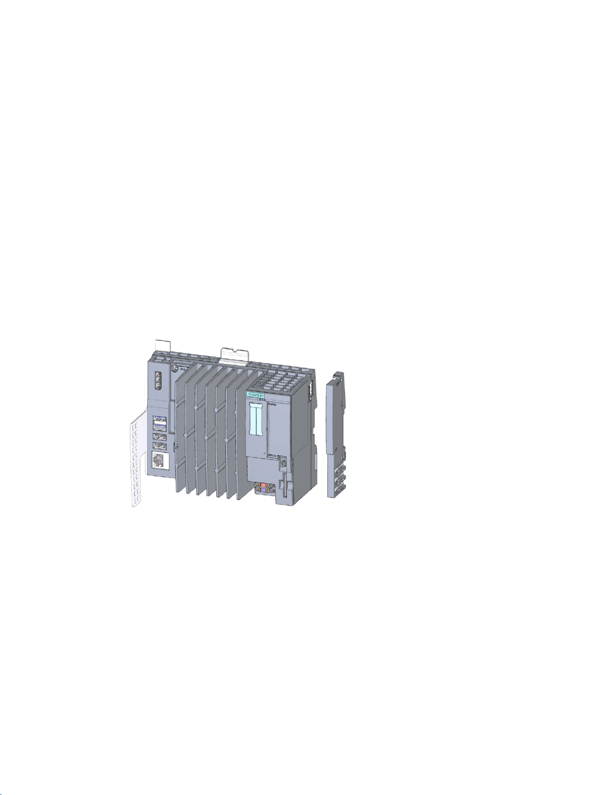
The following figure shows the CPU 1515SP PC2:
Figure 4-1 CPU 1515SP PC2 with supplied accessories
CPU 1515SP PC2 (F/T/TF)
18 Operating Instructions, 09/2018, A5E42603425-AA
Page 20

Product overview
4.2
Characteristics
General characteristics
Additional information
4.2 Characteristics
The CPU 1515SP PC2 is a PC-based automation device in the design of the ET 200SP. It is
used for control and visualization purposes. The supplied IPC DiagBase software provides
basic diagnostics functions and supports you in handling the BIOS.
● A removable CFast card with the following pre-installations is used as storage medium:
– Windows 10 IoT Enterprise operating system (64-bit)
– S7-1500 Software Controller CPU 1505SP, CPU 1505SP F, CPU 1505SP T,
CPU 1505SP TF
– Optionally with HMI: WinCC Runtime Advanced as of V15
● Interfaces:
– An interface for the exchangeable ET 200SP BusAdapters for connection of
PROFINET IO (2 ports) Accessories/spare parts (Page 123)
– An interface for connecting devices using Industrial Ethernet (Gigabit Ethernet)
– 4 interfaces for USB devices (2 x USB 3.0 and 2 x USB 2.0)
– A DisplayPort interface (DPP) for a monitor
– A sealable slot for the CFast card
– A slot for an SD/MMC card as additional optional drive
● Supply voltage 1L+ 24 V DC (SELV/PELV). The connection plug is included in the scope
of delivery.
● The CPU 1515SP PC2 is suitable for use in industrial environments:
– Compact design
– Fan-less operation
– High robustness
● The CPU 1515SP PC2 complies with IP 20 degree of protection and is intended for
installation in a control cabinet.
You can find more information on the system versions and ordering options in the section
Scope of validity of the documentation (Page 6).
CPU 1515SP PC2 (F/T/TF)
Operating Instructions, 09/2018, A5E42603425-AA
19
Page 21

Product overview
4.3
Sample configuration
Configuration
4.3 Sample configuration
The CPU 1515SP PC2 is mounted on a mounting rail according to EN 60715. A modular
system is formed with ET 200SP modules in the central rack. You can also expand the
CPU 1515SP PC2 with fail-safe I/O modules.
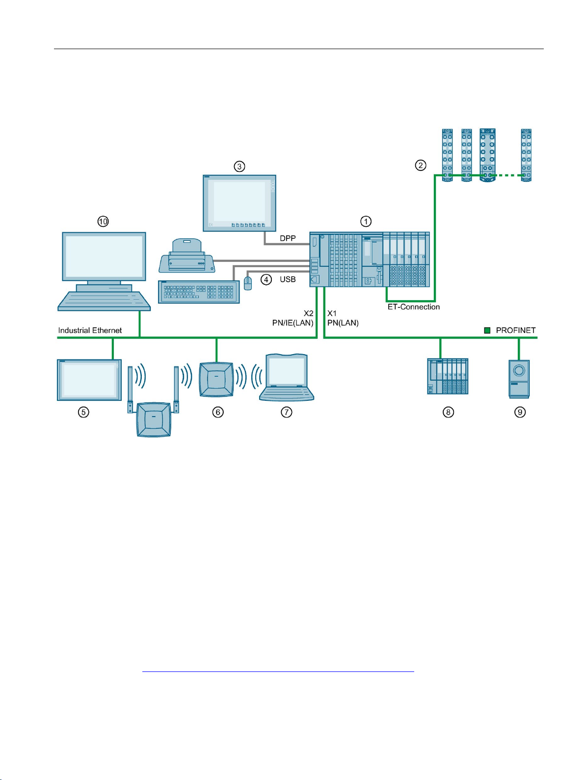
You can use the CPU 1515SP PC2 as PROFINET IO controller. The PROFINET IO devices
are connected via the ports of the X1 PN(LAN) interface using a SIMATIC BusAdapter.
Devices can be connected via Industrial Ethernet using the integrated interface
X2 PN/IE(LAN).
The connection to PROFIBUS can be made using the DP master module.
CPU 1515SP PC2 (F/T/TF)
20 Operating Instructions, 09/2018, A5E42603425-AA
Page 22
Product overview
Sample configuration
①
CPU 1515SP PC2, I/O modules, server module, BusAdapter
②
ET 200AL modules with ET-Connection
③
Flat Panel - Wide Screen Display
④
USB devices: Keyboard, mouse, printer ...
⑤
Industrial Thin Client ITC
⑥
SCALANCE W786
⑦
Field PG
⑧
PROFINET IO device
⑨
Camera
⑩
PC/Programming device
Reference
4.3 Sample configuration
The following figure shows a sample configuration with the CPU 1515SP PC2:
Figure 4-2 Configuration example with the CPU 1515SP PC2
You can find more information about configuring the ET 200AL modules in the system
manual ET 200AL distributed I/O system
(https://support.industry.siemens.com/cs/ww/en/view/89254965
).
CPU 1515SP PC2 (F/T/TF)
Operating Instructions, 09/2018, A5E42603425-AA
21
Page 23
Product overview
4.4
Components
Components of the CPU 1515SP PC2
Component
Function
Figure
4.4 Components
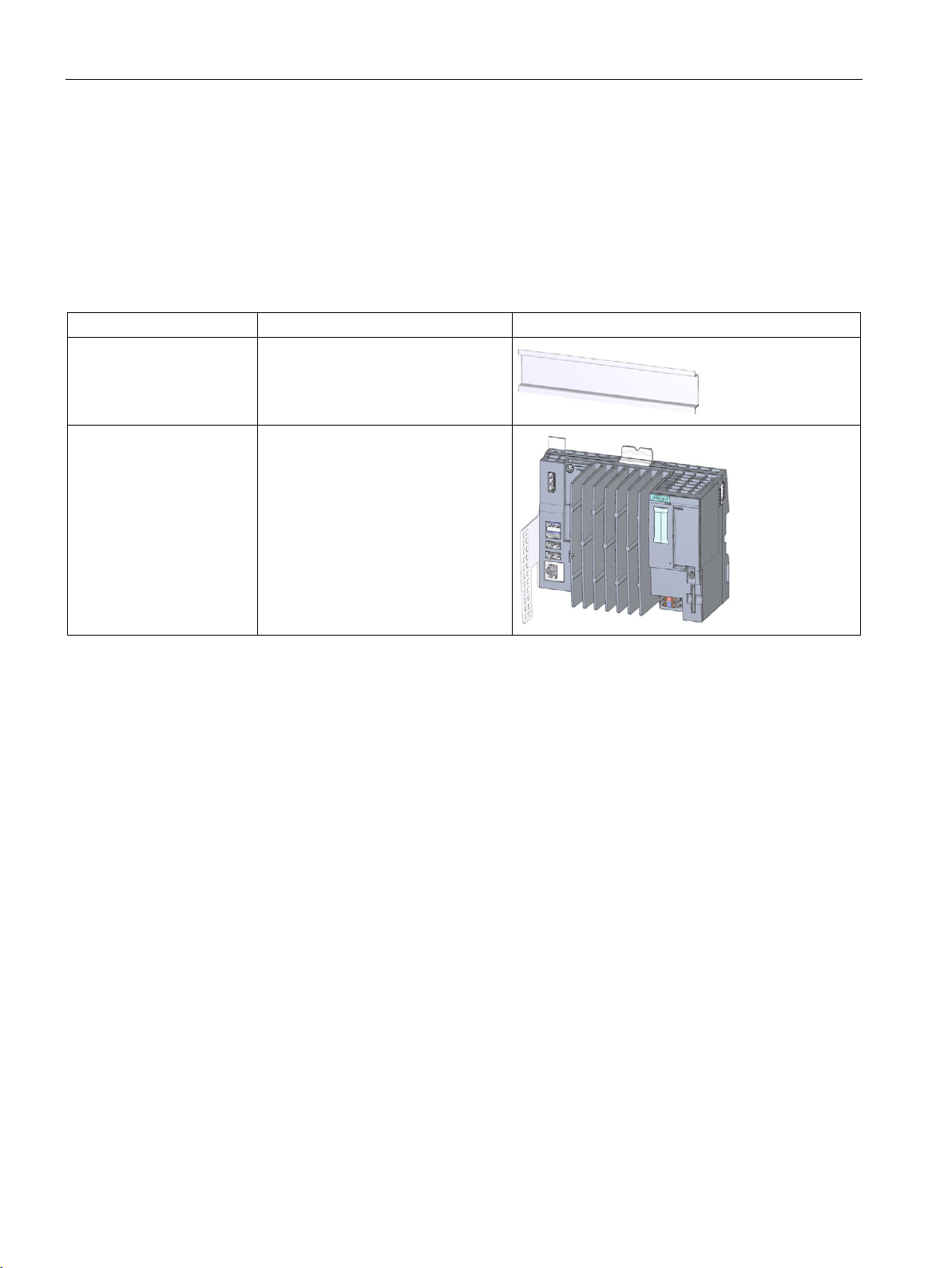
The following table provides an overview of the components of the CPU 1515SP PC2:
Table 4- 1 Components of the CPU 1515SP PC2
Mounting rail in accordance
with EN 60715
CPU 1515SP PC2 CPU with strain relief and white refer-
The mounting rail is the rack for the
CPU 1515SP PC2.
ence labels
CPU 1515SP PC2 (F/T/TF)
22 Operating Instructions, 09/2018, A5E42603425-AA
Page 24
Product overview
Component
Function
Figure
4.4 Components
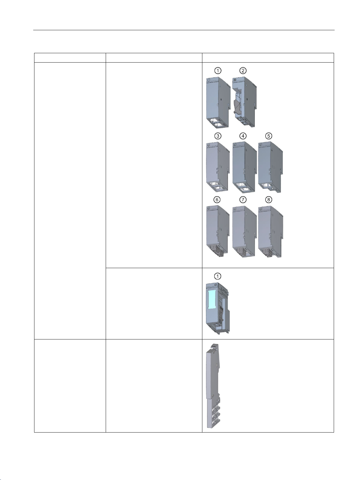
BusAdapter The BusAdapter allows free selection
of the connection technology for
PROFINET IO.
The following versions are available
for CPU 1515SP PC2:
• For standard RJ45 connector
(BA 2×RJ45) ①
• For direct connection of the bus
cable (BA 2×FC) ②
• For POF/PCF fiber-optic cable
(BA 2xSCRJ) ③
• As media converter for POF/PCF
fiber-optic cable ⇔ standard RJ45
connector (BA SCRJ/RJ45)
• As media converter for POF/PCF
fiber-optic cable ⇔ direct connec-
tion of the bus cable
(BA SCRJ/FC)
• For glass fiber-optic cable
(BA 2xLC) ⑥
• As media converter for glass fiber-
optic cable ⇔ standard RJ45 connector (BA LC/RJ45)
• As media converter for glass fiber-
optic cable ⇔ direct connection of
the bus cable (BA LC/FC)
For mixed configuration with an
ET 200AL , you require the
BusAdapter BA-Send 1xFC
(plugged into the BaseUnit BU-Send).
Connect the bus cable for ET-
Connection to the BusAdapter
BA-Send 1xFC.
⑤
④
⑦
⑧
①
Server module The server module completes the
configuration of the
CPU 1515SP PC2 with I/O modules.
The server module is included in the
CPU's scope of delivery.
CPU 1515SP PC2 (F/T/TF)
Operating Instructions, 09/2018, A5E42603425-AA
23
Page 25
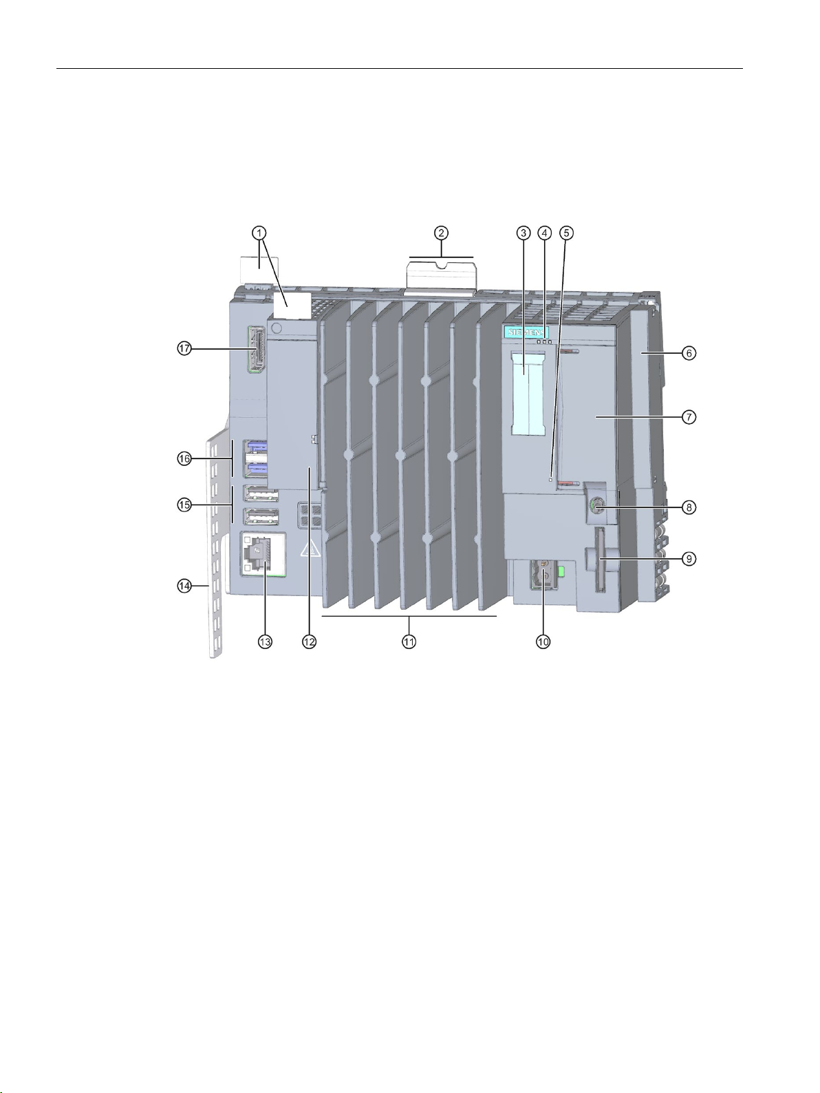
Product overview
4.5
Operator controls and connection elements
View of the module
①
Reference identification labels
②
Mounting rail release
③
Labeling strips
④
LEDs for the current operating state and diagnostic status of the CPU 1505SP
⑤
Power LED
⑥
Server module
⑦
X50:
Slot for the CFast card (flash memory), sealable
⑧
Mode selector
⑨
X51:
Slot for an optional SD/MMC card
⑩
X80:
Connector for 24 V DC supply voltage
⑪
Cooling fins
⑫
X1 PROFINET (LAN):
Slot for BusAdapter for connection of PROFINET IO;
Status display for PROFINET
⑬
X2 PN/IE(LAN):
GbE Ethernet connection with integrated display
⑭
Strain relief
⑮
X62, X63:
2 x USB 2.0 ports
⑯
X60, X61:
2 x USB 3.0 ports
⑰
X70:
DisplayPort interface (DPP)
4.5 Operator controls and connection elements
The following figure shows the operator controls and connection elements of the
CPU 1515SP PC2:
Figure 4-3 View of the CPU 1515SP PC2
CPU 1515SP PC2 (F/T/TF)
24 Operating Instructions, 09/2018, A5E42603425-AA
Page 26

Product overview
Slot for CFast card
Note
Unauthorized access
Seal the cover of the slo
CPU
Slot for SD/MMC card
USB connections
MAC addresses
Assignment
MAC address 1
MAC address 2
MAC address 3
Port X1 P1 (required for LLDP, for example)
MAC address 4
4.5 Operator controls and connection elements
The operating system, Runtime software and project are installed on the supplied
SIMATIC CFast card. The CFast card is the only mass storage device of the
CPU 1515SP PC2.
t to protect the CFast card with the operating system of the
1515SP PC2 from unauthorized access and manipulation.
You can use a SIMATIC SD or MMC card as additional storage drive. This drive can be used
to store data via Windows, for example a backup, but not the operating system, the Runtime
software or the project.
Permitted SD cards: SDHC up to 32 GB, SDXC up to 2 TB.
● 2 x USB 3.0 with I
● 2 x USB 2.0 with I
= 1 A per interface
max
= 0.5 A per interface
max
The MAC address consists of a 3-byte manufacturer ID and a 3-byte device ID (consecutive
number).
Each device is already assigned four MAC addresses in the factory. The front of the
CPU 1515SP PC2 is lasered with the MAC address 1 and 4. With the MAC addresses 2 and
3, the consecutive numbers are incremented. If, for example, the first MAC address is
08-00-06-6B-80-C0, the second MAC address is 08-00-06-6B-80-C1.
Table 4- 2 Assignment of the MAC addresses
X2 PN/IE(LAN)
• Visible in STEP 7 for accessible devices
• Lasered on the front of the CPU (start of the number range)
X1 PROFINET (LAN)
• Visible in STEP 7 for accessible devices
Port X1 P2 R (required for LLDP, for example)
CPU 1515SP PC2 (F/T/TF)
Operating Instructions, 09/2018, A5E42603425-AA
• Lasered on the front of the CPU (end of the number range)
25
Page 27

Product overview
Connector for supply voltage
Mode selector
Position
Meaning
Description
RUN
Operating mode RUN1
The CPU is processing the user program.
The outputs are set to a "safe" state.
For active S7-1500 software controller
CPU memory reset
1
selected
actual
2
See manual S7-1500 Software Controller CPU 1505SP (F), CPU 1507S (F) Version 2
4.5 Operator controls and connection elements
The CPU 1515SP PC2 is equipped with a 2-pin connection terminal for the power supply.
The connection plug for the supply voltage is plugged in when the CPU is shipped from the
factory.
Use the mode selector to set the CPU operating mode.
Table 4- 3 Mode selector positions
STOP Operating mode STOP1 The CPU is not processing the user program.
MRES Memory reset
RUN and STOP indicate the
the CPU 1515SP PC2.
operating state. The RUN and STOP LEDs indicate the
2
only:
operating mode of
CPU 1515SP PC2 (F/T/TF)
26 Operating Instructions, 09/2018, A5E42603425-AA
Page 28

Product overview
4.6
Scope of delivery
Note
The device always comes with the CPU 1515SP PC2
6ES7677
only
Only
4.6 Scope of delivery
label with article number
-2DB40-0AA0, regardless of the order options.
The following components are included in the scope of delivery of the CPUs:
● CPU 1515SP PC2 basic device
● Strain relief with fixing screws
● Server module
● CFast card with the following pre-installations:
– Windows 10 IOT Enterprise operating system (64-bit)
– S7-1500 Software Controller CPU 1505SP
– Optional
of V15
● Restore USB stick for image restore
● Windows-Certificate of Authenticity (CoA)
● Certificate of License (CoL)
●
for CPU 1515SP PC2 (F) with HMI and CPU 1515SP PC2 T/ TF: USB stick with
SIMATIC license keys
● Product information
for CPU 1515SP PC2/CPU 1515SP PC2 F: WinCC RT Advanced as
CPU 1515SP PC2 (F/T/TF)
Operating Instructions, 09/2018, A5E42603425-AA
27
Page 29

5
5.1
Basics
Introduction
Installation location
Installation position
NOTICE
Damage to the modules
50 °C for an installation with up to 32 I/O modules.
The CPU 1515SP PC2 is open equipment. This means you may only set up the CPU in
enclosures, cabinets or electrical equipment rooms and in a dry environment (IP20 degree of
protection). The housings, cabinets and electrical operating rooms must guarantee
protection against electric shock and spread of fire. The requirements regarding mechanical
strength must also be observed. The housings, cabinets, and electrical operating rooms
must not be accessible without a key or tool. Access may only be possible for instructed or
authorized personnel.
Install the CPU 1515SP PC2 in a suitable enclosure/control cabinet with at least IP54 degree
of protection according to EN 60529 and take into consideration the ambient conditions for
operating the devices.
You can install the ET 200SP distributed I/O system in any position. The preferred mounting
position is horizontal mounting on a vertical wall.
Depending on the mounting position, restrictions on ambient temperature and maximum
configuration apply to the CPU 1515SP PC2.
Modules can be damaged if exposed to ambient temperatures higher than permitted.
The following ambient temperatures must not be exceeded during operation:
• Horizontal mounting
• Vertical mounting
60 °C for an installation with up to 32 I/O modules.
55 °C for an installation with up to 64 I/O modules.
Additional information can be found in the section Mechanical and climatic environmental
CPU 1515SP PC2 (F/T/TF)
28 Operating Instructions, 09/2018, A5E42603425-AA
conditions (Page 74).
Page 30

Application planning
5.2
Unpacking the device
When unpacking
NOTICE
Damage to the device during transport and storage
NOTICE
Damage to the device caused by condensation
5.2 Unpacking the device
When unpacking, make sure to check the following:
● Check packaging and contents for visible damage from transport. Damaged or
incomplete devices should never be commissioned.
● Check the delivery for correctness and completeness.
Please inform your Siemens contact partner should you notice any irregularities.
● Keep the supplied documentation and licenses. They belong to the device and are the
proof that you have purchased the software preinstalled on the CFast card.
Documentation and licenses are required for initial commissioning and for any questions
that arise.
● Keep the original packaging in case the device needs to be transported again.
● Note the identification data (Page 30) of the device.
If a device is transported or stored without packaging, it is unprotected from shocks,
vibrations, pressure and moisture. Damaged packaging indicates that environmental
conditions have already had a significant impact on the device.
The device might be damaged.
Do not dispose of the original packaging. Pack the device for transport and storage.
If the device was exposed to low temperatures or extreme variations in temperature during
transport, this may cause moisture to build up on or in the device (condensation). Please
note the specified mechanical and climatic ambient conditions (Page 74).
Moisture can cause short-circuits in the electrical circuits and damage the device.
Proceed as follows to avoid damage:
• Store the device in dry conditions.
• Make sure it adapts to room temperature before commissioning.
• Do not expose the device to direct heat radiation from a heater.
• If condensation has developed, wait until the device is completely dry before you switch
it on.
CPU 1515SP PC2 (F/T/TF)
Operating Instructions, 09/2018, A5E42603425-AA
29
Page 31

Application planning
WARNING
Electric shock and fire hazard from damaged device
5.3
Identification data
5.3 Identification data
A damaged device can carry dangerous voltage and trigger a fire in the machine or plant. A
damaged device has unpredictable properties and states.
Death or severe injury could occur.
Make sure that the damaged device is not installed and commissioned accidentally. Label
the damaged device correspondingly and keep it locked up. Have the device repaired
without delay.
The identification data can be used to clearly identify the device when a repair is necessary.
Note the following data:
● Printed on the nameplate of the device, please find the following information:
– Article number
– Serial number
– The first and the last MAC address
● Depending on the scope of delivery, the "Certificate-of-License" is provided as proof of
license. This document is valid for the following product:
– S7-1500 Software Controller CPU 1505SP
– S7-1500 Software Controller CPU 1505SP F/T/TF
– WinCC Runtime Advanced V15
● The "Microsoft Windows Product Key" can be found on the "Certificate of Authenticity"
label.
CPU 1515SP PC2 (F/T/TF)
30 Operating Instructions, 09/2018, A5E42603425-AA
Page 32

Application planning
5.4
Installation location
Introduction
Mounting rail
Note
If the ET 200SP distributed I/O system is exposed to vibration and shock loads, both ends of
the ET 200SP system assembly must be mechanically fixed to the mounting rail (e.g using
8WA1010
the side.
Note
If the ET 200SP distributed I/O system is exposed to high vibration and shock load, we
recommend that you screw the mounting rail to the mounting surface at int
200 mm.
Note
Mounting rails of other manufacturers
If you use mounting rails from other manufacturers, ensure that they have the properties
required for your climatic and mechanical ambient conditions.
5.4 Installation location
Install the CPU 1515SP PC2 in a suitable housing/control cabinet with sufficient mechanical
strength, fire protection and at least IP54 degree of protection according to EN 60529, and
take into consideration the ambient conditions for operating the devices.
You must ground the mounting rail separately in the control cabinet. Exception: If you install
the rail on grounded, zinc-plated mounting plates, there is no need to ground the rail
separately.
-1PH01 ground terminals). This measure prevents the ET 200SP from shifting to
ervals of approx.
Suitable surface finishes are:
● Steel strip in accordance with Appendix A of EN 60715 or
● Tinned steel strip. We recommend the use of the mounting rails in section (Page 123).
CPU 1515SP PC2 (F/T/TF)
Operating Instructions, 09/2018, A5E42603425-AA
31
Page 33
Application planning
Minimum clearances
Installation rules
Note
Install the CPU
5.4 Installation location
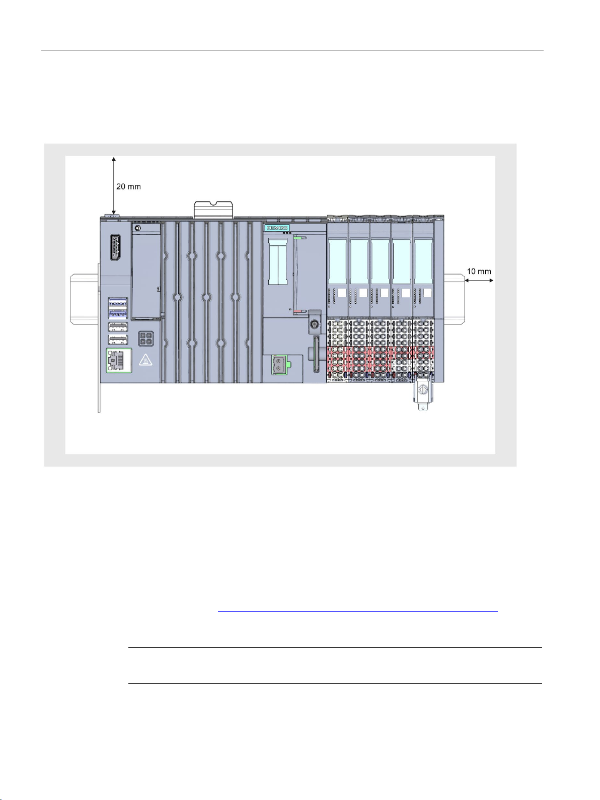
Make sure to maintain the following minimum clearances when installing the
CPU 1515SP PC2.
Figure 5-1 Minimum clearances
● After the CPU 1515SP PC2, there is a BaseUnit BU..D with incoming supply voltage L+
(light-colored terminal box).
● This is followed by BaseUnits BU..B (with dark-colored terminal box).
● The respective corresponding I/O modules can be connected to the BaseUnits.
Suitable combinations of BaseUnits and I/O modules can be found in the ET 200SP
System Manual (http://support.automation.siemens.com/WW/view/en/84133942
● The server module completes the installation.
1515SP PC2 only with disconnected supply voltage.
CPU 1515SP PC2 (F/T/TF)
32 Operating Instructions, 09/2018, A5E42603425-AA
).
Page 34

Application planning
5.5
Hardware configuration
Maximum mechanical configuration
Electrical maximum configuration
USB load
and
and
and
Address space
5.5 Hardware configuration
As soon as one of the following rules applies, the maximum configuration has been reached.
Backplane bus length: Maximum 1 m mounting width (without CPU 1515SP PC2, including
server module)
The number of operable I/O modules of a potential group is limited by the
● Power consumption of the I/O modules
● Power consumption of the components supplied via these I/O modules
The maximum current-carrying capability of the terminals on the BaseUnit L+/ground is 10 A.
When using the CPU 1515SP PC2 with the maximum configuration, the USB load must also
be considered:
● Horizontal mounting
– Ambient temperature of 0 to 60 °C with maximum 32 I/O modules
(500 mA) USB load
– Ambient temperature of 0 to 55 °C with maximum 64 I/O modules
(900 mA) + 2 x low-current (500 mA) USB load
● Vertical mounting
– Ambient temperature of 0 to 50 °C with maximum 32 I/O modules
(500 mA) USB load
The address space is predefined. However, you can adjust the address space in the user
program.
4 x low-current
2 x high-current
4 x low-current
CPU 1515SP PC2 (F/T/TF)
Operating Instructions, 09/2018, A5E42603425-AA
33
Page 35
6
6.1
Installing the device
Requirements
Required tools
Fixing strain relief
Installing the CPU 1515SP PC2
The mounting rail is fitted.
3 to 3.5 mm screwdriver (only to fix the strain relief and dismantle the BusAdapter)
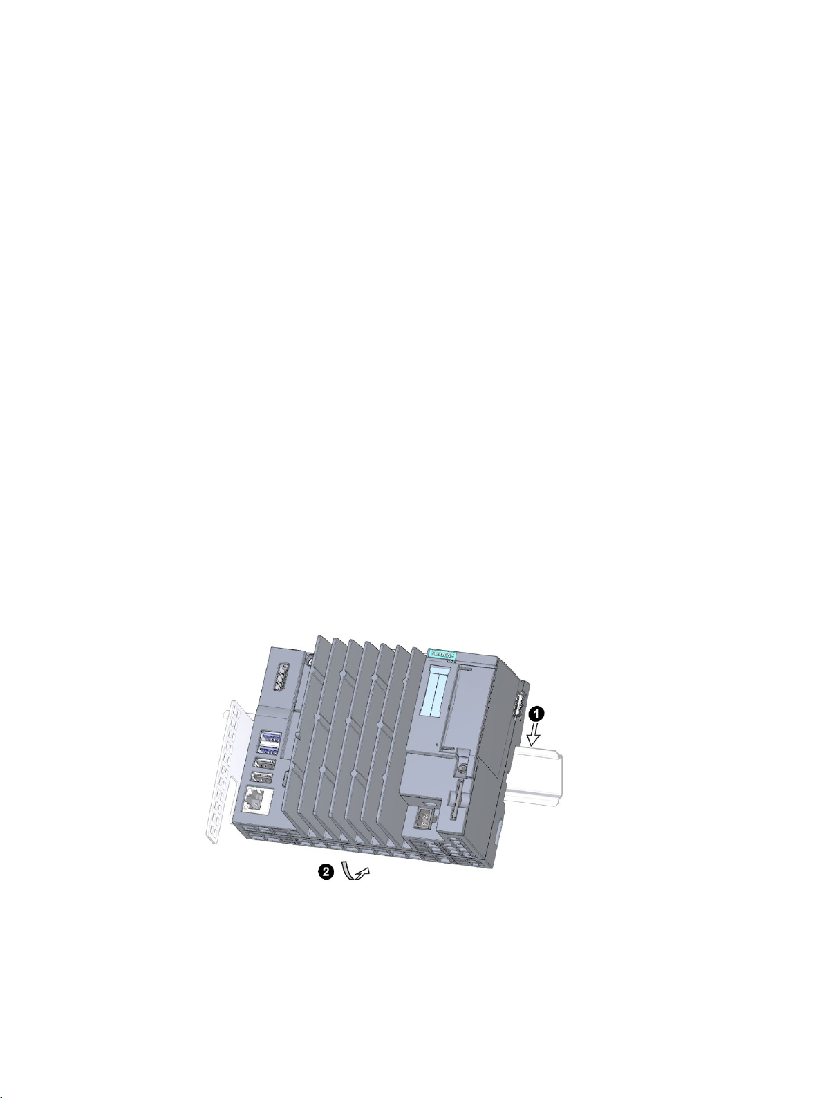
Fix the strain relief to the top and bottom of the left-hand side of the CPU 1515SP PC2 with
the supplied screws.
1. Install the CPU on the mounting rail.
2. Swivel the CPU back until you hear the mounting rail release click into place
3. To check that the CPU has correctly clicked into place, pull on the underside of the
enclosure.
Figure 6-1 Installing the CPU 1515SP PC2
CPU 1515SP PC2 (F/T/TF)
34 Operating Instructions, 09/2018, A5E42603425-AA
Page 36

Installation
Uninstalling the CPU 1515SP PC2
Note
It is not necessary
6.1 Installing the device
The BaseUnits with the I/O modules are located to the right of the CPU 1515SP PC2:
1. Switch off the supply voltage on the CPU.
2. Press the mounting rail release button on the first BaseUnit and, at the same time, move
the CPU parallel to the left until it comes off the rest of the module group.
Note: The mounting rail release button is located above the CPU.
3. While pressing the mounting rail release button on the CPU, swivel the CPU out of the
mounting rail.
to remove the BusAdapter from the CPU 1515SP PC2.
CPU 1515SP PC2 (F/T/TF)
Operating Instructions, 09/2018, A5E42603425-AA
35
Page 37

7
7.1
Notes on connection
Note
Rules and regulations for operation
Observe the information contained in the
distributed I/O system (
in the function manual Designing interference
(
NOTICE
Risk of hazardous system states
http://support.automation.siemens.com/WW/view/en/59193566).
Wiring
section in the system manual ET 200SP
http://support.automation.siemens.com/WW/view/en/84133942) and
-free controllers function manual
If you remove and insert I/O devices with the supply voltage switched on, this can result in
hazardous system states.
Injury to persons and damage to the machine or plant could result.
Therefore, I/O devices can only be inserted and removed when the supply voltage is
switched off.
Only connect I/O devices which are suitable for use in industrial environments according to
EN 61000-6-2 / IEC 61000-6-2.
CPU 1515SP PC2 (F/T/TF)
36 Operating Instructions, 09/2018, A5E42603425-AA
Page 38
Wiring
7.2
Terminal and block diagram
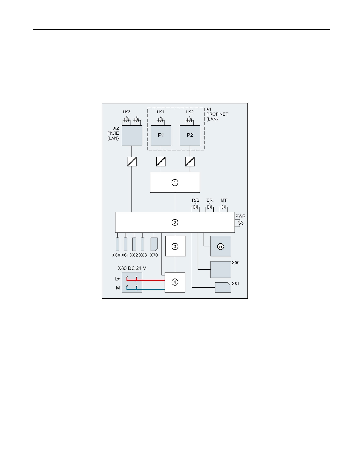
Block diagram
①
Switch
X1 PN(LAN)
PROFINET interface X1
②
Electronics
P1
PROFINET interface X1 Port 1
③
Backplane bus interface
P2
PROFINET interface X1 Port 2
④
Internal supply voltage
L+
24 V DC supply voltage
⑤
Mode selector
M
Ground
X50
CFast card
LK1, LK2
LED Link TX/RX
X51
SD/MMC card
LK3
LED Link
X60, X61
USB 3.0 interfaces, max. 0.9 A
R/S
RUN/STOP LED (yellow/green)
X62, X63
USB 2.0 interfaces, max. 0.5 A
ER
ERROR LED (red)
X70
DPP interface
MT
MAINT LED (yellow)
X80 24 V DC
Infeed of supply voltage
PWR
POWER LED (yellow/green)
X2 PN/IE(LAN)
Ethernet interface X2
7.2 Terminal and block diagram
The following figure shows the block diagram for the CPU 1515SP PC2.
Figure 7-1 Block diagram for the CPU 1515SP PC2
CPU 1515SP PC2 (F/T/TF)
Operating Instructions, 09/2018, A5E42603425-AA
37
Page 39

Wiring
7.3
Electrical configuration
Non-isolated configuration
Note
Unlike the ET 200SP distributed I/O system, the CPU
with a non
7.3 Electrical configuration
1515SP PC2 can only be operated
-isolated configuration.
CPU 1515SP PC2 (F/T/TF)
38 Operating Instructions, 09/2018, A5E42603425-AA
Page 40
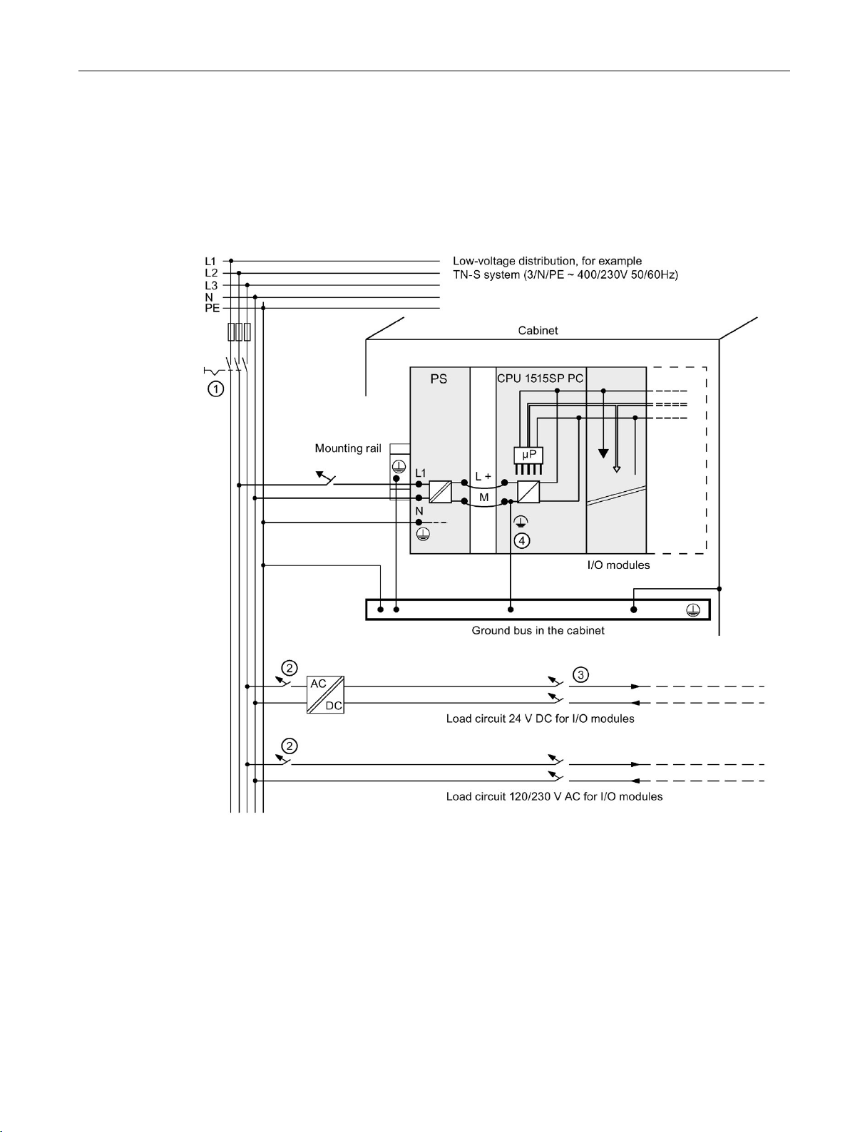
Wiring
①
Master switch
②
Short-circuit and overload protection
③
Load current supply (galvanic isolation)
④
This connection is established automatically with the CPU 1515SP PC2.
chosen for demonstration purposes only.
7.3 Electrical configuration
The following figure shows the overall configuration of a CPU 1515SP PC2 with power
supply from a TN-S system. The power supply supplies the CPU 1515SP PC2 and the load
circuit for the 24 V DC modules.
For the CPU 1515SP PC2, there is a fixed connection between the ground infeed terminal
and the contact springs to the mounting rail. You must ground the mounting rail separately in
the control cabinet.
The represented layout of the power connections does not correspond to the actual layout; it was
Figure 7-2 Connecting the load voltage reference potential
CPU 1515SP PC2 (F/T/TF)
Operating Instructions, 09/2018, A5E42603425-AA
39
Page 41

Wiring
7.4
Connecting devices to networks
Ethernet
Note
Use a Category 5e Ethernet
PROFINET
PROFIBUS
7.4 Connecting devices to networks
The following options are available for integrating devices into existing or planned system
environments and networks.
You can use the integrated Ethernet interface X2 PN/IE(LAN) (10/100/1000 Mbps) for
communication and data exchange with automation devices, for example, SIMATIC S7.
Only ASCII characters are permitted in the name of the X2 PN/IE(LAN) interface in the
TIA Portal, e.g. PROFINET_2.
You need suitable software to do this: STEP 7, WinCC, SIMATIC NET.
cable (Cat-5e cable) for operation with 1000 Mbps.
PROFINET operation is possible via the X1 PN(LAN) interface and the approved
BusAdapter.
The connection to PROFIBUS can be made using the DP master module.
CPU 1515SP PC2 (F/T/TF)
40 Operating Instructions, 09/2018, A5E42603425-AA
Page 42
Wiring
7.5
Securing cables
WARNING
Flying sparks due to loose cables
Requirements
Procedure
7.5 Securing cables
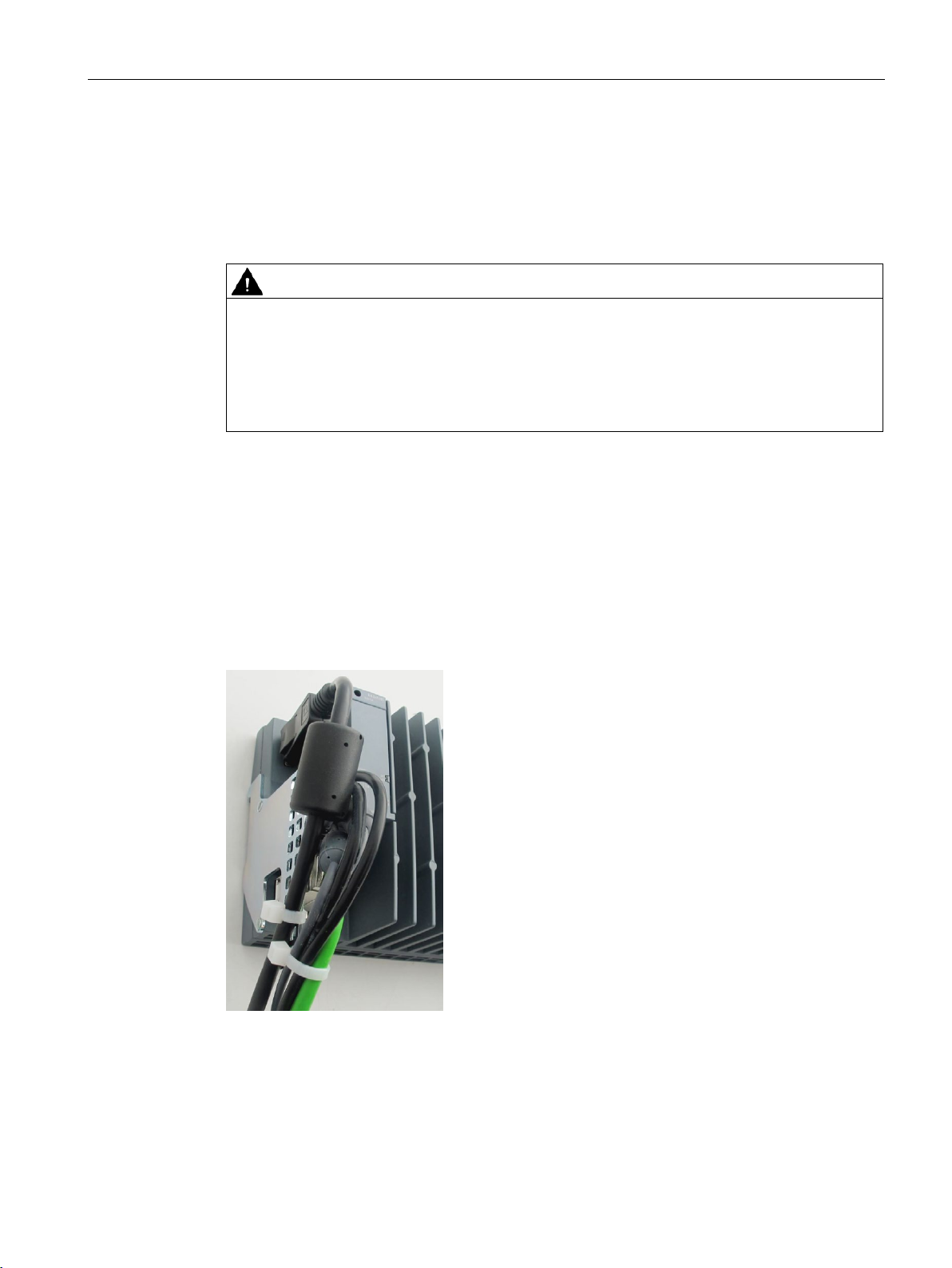
The strain relief for connecting cables prevents the USB cables and PROFINET connectors
detaching from the CPU 1515SP PC2. The strain relief is included in the scope of delivery.
Risk of explosion in hazardous areas.
USB cables and PROFINET connectors may detach from the device in the case of strong
oscillation and high vibrating loads.
Attach these cables to the strain relief of the device using cable ties.
● The strain relief is fixed to the CPU.
● The CPU is installed.
Secure the USB and PROFINET cables to the strain relief using cable ties.
Figure 7-3 Secured cables
CPU 1515SP PC2 (F/T/TF)
Operating Instructions, 09/2018, A5E42603425-AA
41
Page 43
8
8.1
Notes on commissioning
WARNING
Improper commissioning in hazardous areas
NOTICE
Condensation in the device
NOTICE
Data loss
Device failure or risk of explosion in hazardous areas.
• Do not commission the device unless it is fully mounted and connected according to the
specifications in the section Wiring (Page 36).
• Before commissioning, please consider the effects on other devices in the plant.
Damage to the device due to condensation if the temperature between transport or storage
and the installation point differs.
Before commissioning the device, leave it to stand until it is dry.
Data loss may occur if write filters are used incorrectly.
Therefore, note the information on write filters.
The following configurable write filter is available under Windows 10:
• Unified Write Filter (UWF) (Page 57)
CPU 1515SP PC2 (F/T/TF)
42 Operating Instructions, 09/2018, A5E42603425-AA
Page 44

Commissioning
8.2
Basic commissioning procedure
Step
Execution
Section
1
Requirements
8.2.1 (Page 43)
2
Preparing commissioning
8.2.2 (Page 43)
3
Commissioning procedure
8.2.3 (Page 43)
8.2.1
Requirements
8.2.2
Preparing commissioning
Procedure
Result
8.2.3
Commissioning procedure
Note
The initial commissioning is not possible with a Multitouch panel,
only available after the installation of the operating system.
8.2 Basic commissioning procedure
The following requirements must be met before you commission the Open Controller for the
first time:
● The CPU 1515SP PC2 is mounted.
● The supplied CFast card is inserted.
● No data carriers are connected via USB.
When the requirements are met, proceed as follows with the commissioning:
1. Connect a monitor using a DisplayPort cable.
2. Connect a keyboard and a mouse to the CPU via USB.
The Open Controller is prepared for commissioning.
When you start up your CPU 1515SP PC2 for the first time, basic settings and the
administrator password are queried. The device is then automatically set up for the operating
system that is installed on the CFast card. Restart the device after the operating system has
been set up.
CPU 1515SP PC2 (F/T/TF)
Operating Instructions, 09/2018, A5E42603425-AA
as the Multitouch driver is
43
Page 45

Commissioning
Procedure
NOTICE
Faulty installation
not
Information on users/user groups in Windows
Note
When you assign a password, change the ent
using the Windows user administration.
8.2 Basic commissioning procedure
When the requirements (Page 43) are met and the preparations for commissioning
(Page 43) are complete, proceed as follows with the commissioning:
1. Connect the power supply.
→ The PWR LED lights up yellow first, then green.
→ The device carries out the hardware initialization.
2. Wait until the Siemens logo disappears from the screen.
3. Follow the instructions on the screen to configure the device:
– Set <Language>, <Country/region>, <App language>, <Keyboard layout>, <Time
zone for>
– Accept license conditions
– Setting the account
4. Finally, you will be prompted to restart the device.
If you change the device during the installation, the installation will be disrupted and the
operating system will not be installed correctly. The operational reliability of the device and
the plant is endangered.
Do
switch off the device during the entire installation process.
A user "Operator" with standard user rights is already created on the Windows system.
The user is in a user group "SIEMENS TIA Engineer". This grants the user the rights to use
the installed SIMATIC software products.
To use the CPU 1515SP PC2 directly, the Windows "Autologon" function is enabled for the
"Operator" user. No password is preset.
ry for the "Autologon" function accordingly
CPU 1515SP PC2 (F/T/TF)
44 Operating Instructions, 09/2018, A5E42603425-AA
Page 46

Commissioning
Result
8.3
Initial commissioning an open controller
Step
Execution
Section
1
Creating the configuration of the Open Controller
8.3.1 (Page 45)
2
Setting the IP address
8.3.2 (Page 46)
ler
4
Establishing the HMI connection
8.3.4 (Page 47)
5
Downloading a project to the target system
8.3.5 (Page 47)
6
Transferring the license key
8.3.6 (Page 48)
7
Switching the Open Controller on/off
8.3.7 (Page 50)
8.3.1
Creating the configuration of the Open Controller
Requirements
8.3 Initial commissioning an open controller
● The Windows 10 IOT Enterprise operating system (64-bit) is installed.
● The "Operator" user is logged on automatically.
● The software controller and WinCC Runtime Advanced, if required, are ready for use.
● For administrative purposes, the "Operator" user can be logged off and the administrator
created during commissioning can be logged on.
● The operating system's start screen is displayed after each startup.
3 Changing the properties of the Software Control-
8.3.3 (Page 46)
The following requirements must be met before you can create the configuration of the Open
Controller:
● TIA Portal V15 + HSP 0269 or TIA Portal ≥ V15 SP1 must be installed.
● You have started the TIA Portal and created a new project.
CPU 1515SP PC2 (F/T/TF)
Operating Instructions, 09/2018, A5E42603425-AA
45
Page 47

Commissioning
Creating the configuration
CPU 1515SP PC2 / CPU 1515SP PC2 F/T/TF:
CPU 1515SP PC2 + HMI / CPU 1515SP PC2 F + HMI:
8.3.2
Setting the IP address
8.3.3
Changing the properties of the S7-1500 Software Controller
8.3 Initial commissioning an open controller
To create the configuration in the TIA Portal, follow these steps:
1. Double-click "Add new device" in the project tree.
2. Select "PC systems > SIMATIC S7 Open Controller > ET 200SP Open Controller >".
3. Select the required device.
4. Select the desired version and click "OK".
The configured Open Controller is displayed in the device view.
5. The following interfaces can be seen in the Open Controller:
– Onboard interface X2 (GB Ethernet Windows interface) that is assigned directly to the
PC station (1 port)
– Exchangeable BusAdapter that is assigned directly to the Software Controller (2 ports)
6. The following preconfigured components can be seen in the device view:
–
Controller
–
Controller and WinCC Runtime Advanced
CPU 1505SP (F/T/TF) Software
CPU 1505SP (F) Software
7. Insert the server module from the hardware catalog.
The server module forms the termination of the CPU with the I/O modules. If no server
module is configured, the server module is added automatically during compiling.
Set the IP address as follows:
● BusAdapter [X1]: The configured IP address becomes effective on the Open Controller
after a download. To go online via the [X1] interface, the configured address must match
the [X1] address entered in the panel of the software controller.
● Onboard interface [X2]: The configured IP address should be identical to the Windows
IP address of the Open Controller.
Information on the property of the CPU is available in the Inspector window under
"Properties". You can change these properties if required.
CPU 1515SP PC2 (F/T/TF)
46 Operating Instructions, 09/2018, A5E42603425-AA
Page 48

Commissioning
8.3.4
Establishing the HMI connection
Procedure
Reference
8.3.5
Downloading a project to the target system
Key statement
Note
Note that the options available to you always depen
8.3 Initial commissioning an open controller
The WinCC RT software is integrated in the SIMATIC HMI devices (e.g.
Basic/Comfort/Mobile Panel) and permits data exchange over HMI connections.
No HMI connection exists between the WinCC RT Advanced software and the
S7-1500 Software Controller at the time of the configuration.
To establish a HMI connection between the WinCC RT Advanced software on the
S7-1500 Software Controller, proceed as follows:
1. In the network view, switch to "Connections".
2. Click on WinCC RT Advanced.
3. Draw a line from the WinCC RT Advanced software to the S7-1500 Software Controller
(e.g. CPU 1505SP) while keeping the mouse button pressed.
A network connection is established between the two devices.
You can find additional information on configuring an HMI connection in the TIA Portal online
help or in the STEP 7 and WinCC Engineering V15
(https://support.industry.siemens.com/cs/ww/en/view/109755202
) system manual.
To set up your automation system, you need to download the project data you generated
offline to the connected devices. This project data is generated, for example when
configuring hardware, networks, and connections or when programming the user program or
when creating recipes. The first time you download, the entire project data is downloaded.
During later download operations, only changes are downloaded.
Proceed as follows to download the configuration:
1. Select the complete PC system in the device view.
2. Right-click on the PC system.
3. Select the option you require in the "Download to device" menu command.
CPU 1515SP PC2 (F/T/TF)
Operating Instructions, 09/2018, A5E42603425-AA
d on the selected device.
47
Page 49

Commissioning
Note
The first TIA Portal download must
Only ASCII characters are permitted in the name of the X2
TIA
Reference
8.3.6
Transferring license keys
Licensing the software
Note
No
V2.x.
Requirements
UWF must be deactivated
8.3 Initial commissioning an open controller
4. Select the interfaces with which you want to establish the online connection to the device.
You have the option of showing all compatible devices by selecting the corresponding
option and clicking the "Start search" command.
be via the "X2" interface.
PN/IE(LAN) interface in the
Portal, e.g. PROFINET_2.
5. Download and compile the project.
The hardware configuration and the first download are now completed.
Additional information on the possible options for downloading is available in the online help
of the TIA Portal.
For the following products, you need to transfer the product-specific license key with the
Automation License Manager (ALM)
● WinCC RT Advanced incl. PowerTag
● CPU 1505SP T/TF
license key is required to operate the S7-1500 Software Controller CPU 1505SP (F)
● Initial commissioning was successfully completed.
● Windows 10 IoT Enterprise (64-bit) has been started.
● The extended write filter
before commissioning:
on the CPU 1515SP PC2.
CPU 1515SP PC2 (F/T/TF)
48 Operating Instructions, 09/2018, A5E42603425-AA
Page 50

Commissioning
Transferring license keys with local configuration
Start > Siemens Automation > Automation License
Manager
Transferring license keys via programming device/PC
Start > Siemens Automation > Automation License Manager
Edit > Connect computer
Backing up license keys for restore and repair
Note
Loss of license keys
A SIMATIC license key cannot be copied or duplicated. No more license key copies exist on
the USB stick once you have dragged the license keys from the USB stick to your
CPU
Secure your purchased license keys before
case of repair. To do this, move the license keys to a USB stick and
place.
Reference
Start > All Programs > Siemens
Automation > Documentation
8.3 Initial commissioning an open controller
The
Automation License Manager
Open the software using the icon on the desktop or a menu command.
is pre-installed on the CPU 1515SP PC2.
1. In the Windows start bar, select
.
2. Follow the instructions of the
Automation License Manager
The
Automation License Manager
is pre-installed on a programming device/PC with STEP 7
and the CPU 1515SP PC2.
1. Connect the CPU 1515SP PC2 to a programming device/PC.
2. Connect the supplied USB stick to the programming device/PC.
3. Select the menu command
4. Select the menu command
CPU 1515SP PC2.
5. if the option "Forbid license keys transfer from local computer" is disabled on the source
computer, drag the license keys from the USB stick to the system partition C: of the
CPU 1515SP PC2.
.
.
and enter the IP address of the
1515SP PC2.
restoring the delivery state (Restore) or in the
If an error occurs on your license keys on the CPU 1515SP PC2, please contact your
Siemens representative. Make sure to have the "Certificate of License" (CoL) to hand.
For additional information on licenses, refer to the
You can find the manual on the CPU 1515SP PC2 under
http://support.automation.siemens.com/WW/view/en/56956174).
(
You can find more information on the UWF write filter in the section: Protective function for
data carriers (Page 57).
and on the Internet
CPU 1515SP PC2 (F/T/TF)
Operating Instructions, 09/2018, A5E42603425-AA
Automation License Manager
keep this stick in a safe
manual.
49
Page 51

Commissioning
8.3.7
Switching the Open Controller on/off
Requirements
Switching on the CPU 1515SP PC2
Switching off the CPU 1515SP PC2
Start > Power > Shut down
8.3 Initial commissioning an open controller
Initial commissioning was successfully completed.
Proceed as follows to switch on the CPU 1515SP PC2:
1. Switch on the power supply of the CPU.
The Boot Manager GRUB2DOS starts.
2. Select the mode in which the CPU 1515SP PC2 should start:
– Default: with the Windows operating system and the S7-1500 software controller
– Only with the Windows operating system (e.g. with updates)
Proceed as follows to switch off the CPU 1515SP PC2:
1. Use the Windows function
The PWR LED changes from green to yellow.
The Windows function shuts down the Windows operating system and the S7-1500
software controller.
If the device will not be used for a longer period after the shutdown, de-energize the device.
to switch off.
CPU 1515SP PC2 (F/T/TF)
50 Operating Instructions, 09/2018, A5E42603425-AA
Page 52
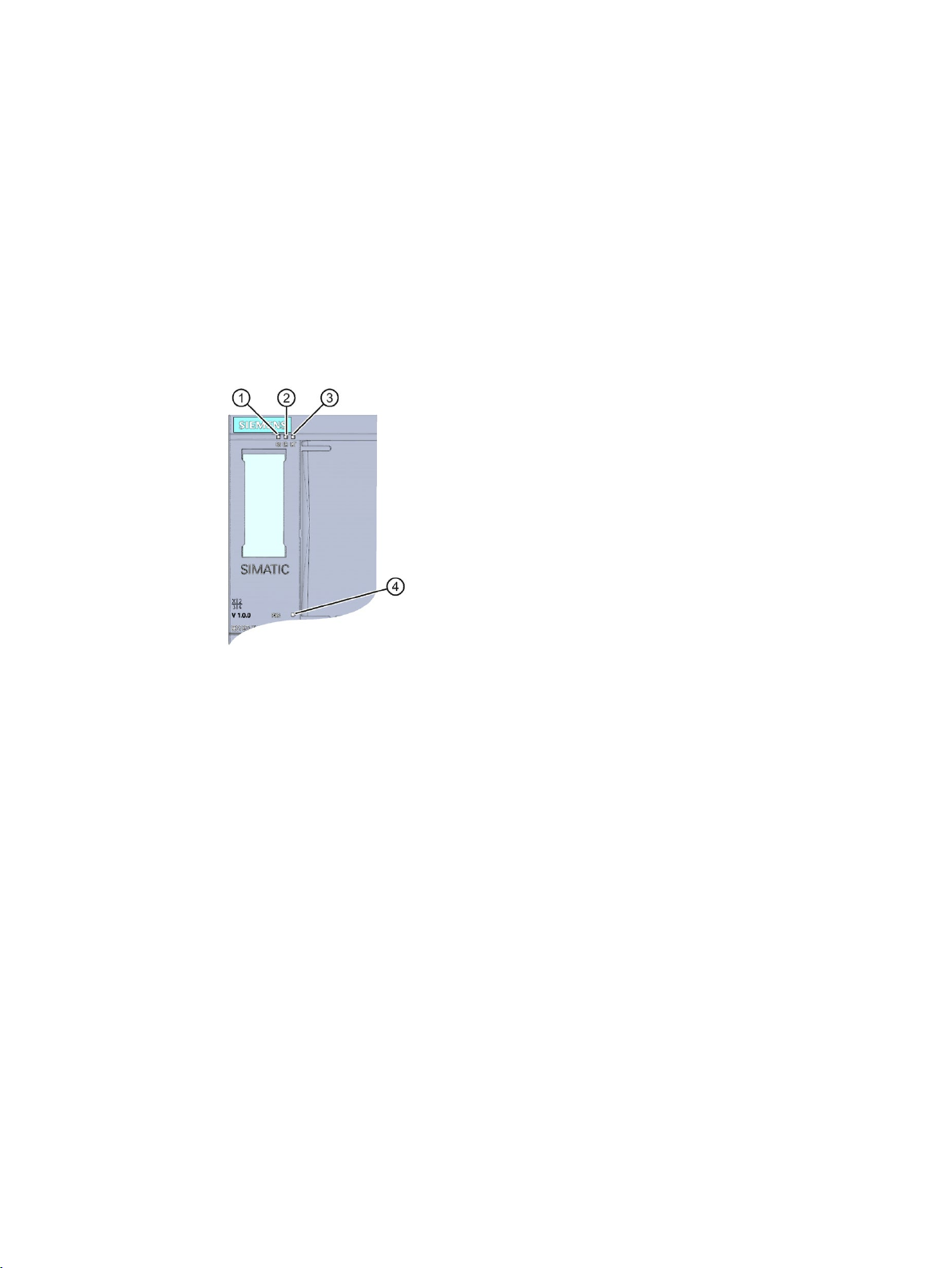
9
9.1
Status and error display
LED display
①
RUN/STOP LED (yellow/green LED)
②
ERROR LED (red LED)
③
MAINT LED (yellow LED)
④
POWER LED (yellow/green LED)
The following figure shows the LED displays of the CPU 1515SP PC2.
Figure 9-1 LEDs of the CPU 1515SP PC2
CPU 1515SP PC2 (F/T/TF)
Operating Instructions, 09/2018, A5E42603425-AA
51
Page 53
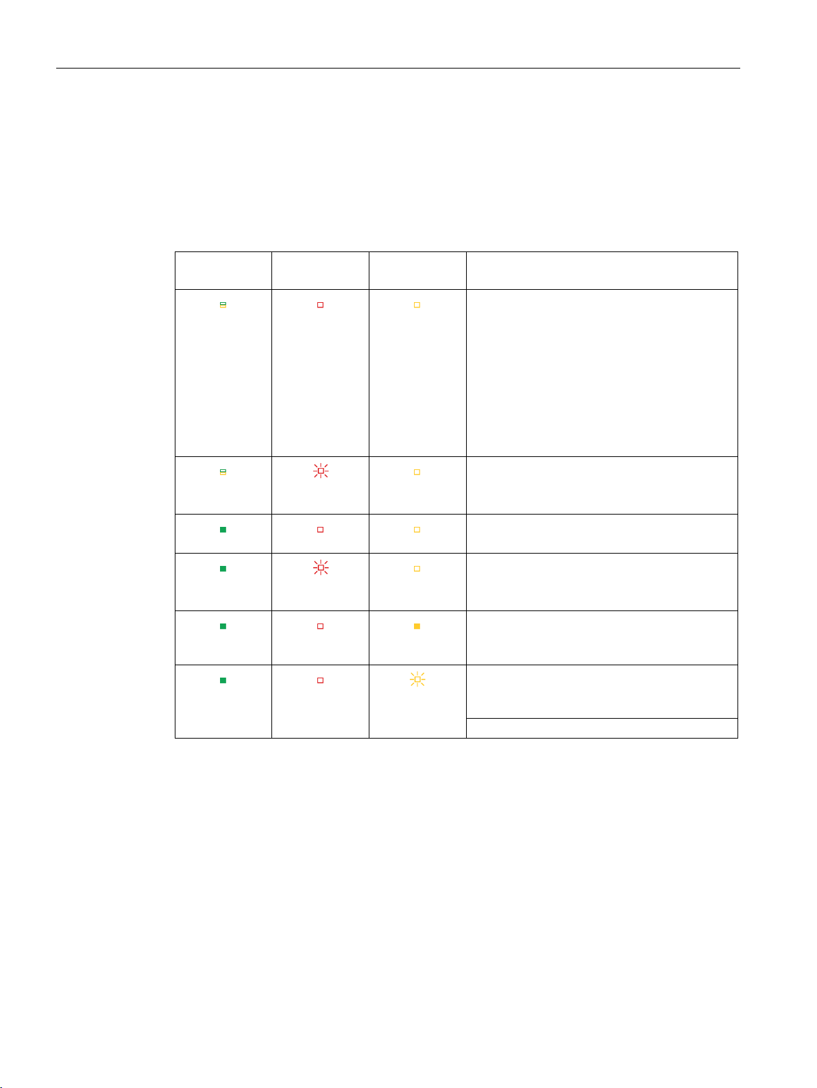
Interrupt, error and system messages
Meaning of the LED displays with active S7-1500 Software Controller
RUN/STOP
LED
ERROR LED
MAINT LED
Meaning
figuration via TIA Portal).
red
LED green
LED off
LED off
red
within a foreseeable period.
9.1 Status and error display
The CPU 1515SP PC2 has three LEDs to indicate the current operating state and
diagnostics status.
The following table shows the meaning of the color combinations of the LED displays in
connection with the S7-1500 Software Controller.
Table 9- 1 Meaning of the LED displays
LED off
LED off
LED green
LED green
LED green
LED off
LED flashes
LED flashes
LED off
LED off
LED off
LED off
LED off
LED lights up
yellow
LED flashes
yellow
POWER OFF
Starting of the CPU 1515 SP PC2 in "Windows
only" mode
No power supply.
Software Controller of the CPU 1515SP PC2:
• is not downloaded
• is in the operating state Power OFF
Use of the hardware LEDs was disabled (con-
An error has occurred.
Software Controller of the CPU 1515SP PC2 is
in RUN mode.
A diagnostics event is pending.
Maintenance demanded for the plant.
The affected hardware must be exchanged
within a short period.
Maintenance required for the plant.
You must exchange the affected hardware
Firmware update successfully completed
CPU 1515SP PC2 (F/T/TF)
52 Operating Instructions, 09/2018, A5E42603425-AA
Page 54
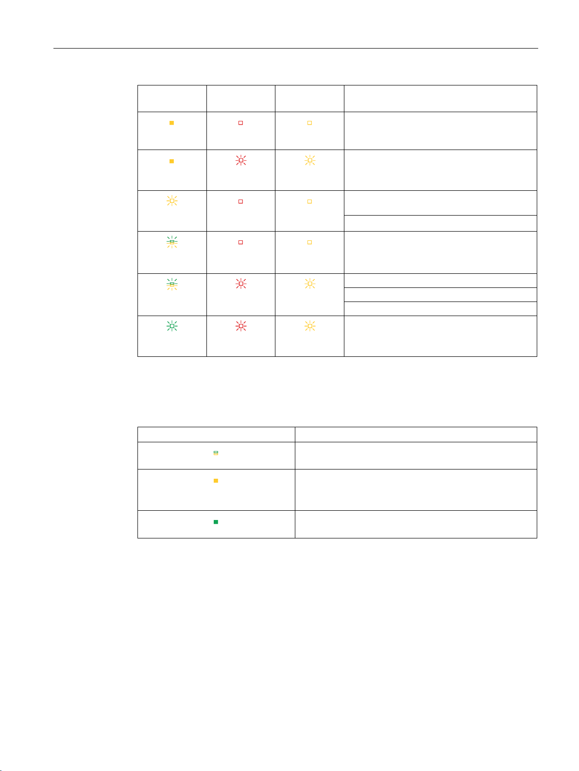
Interrupt, error and system messages
RUN/STOP
LED
ERROR LED
MAINT LED
Meaning
yellow
red
yellow
yellow
STOP, e.g. ramp-up after STOP.
yellow/green
yellow/green
Startup (CPU booting)
Test of LEDs during startup, inserting a module.
LED flashing test
green
red
red
POWER LED
POWER LED
Meaning
LED off
LED green
Booting or operation of the operating system
9.1 Status and error display
LED lights up
LED lights up
yellow
LED flashes
LED flashes
LED flashes
LED flashes
LED off
LED flashes
LED off
LED off
LED flashes
red
LED flashes
LED off
LED flashes
LED off
LED off
LED flashes
yellow
LED flashes
Software controller of the CPU is in the operating state STOP.
The user program is causing an error.
CPU is performing internal activities during
Loading the user program
Startup (transition from STOP → RUN)
CPU defective
Table 9- 2 POWER LED
LED lights up yellow
No supply voltage or supply voltage too low
Supply voltage present;
running through BIOS phase;
operating system is shut down
Supply voltage present;
CPU 1515SP PC2 (F/T/TF)
Operating Instructions, 09/2018, A5E42603425-AA
53
Page 55

10
10.1
Monitoring functions
10.1.1
Requirements
Introduction
Monitoring software
SIMATIC IPC DiagBase
Note
For additional information,
software.
SIMATIC IPC DiagMonitor
The CPU 1515SP PC2 has monitoring functions that you can use with the corresponding
monitoring software.
The following display, monitoring and control functions are available:
● Temperature monitoring
● Monitoring of drives with S.M.A.R.T. functionality
● Operating hours counter (information on the total runtime)
● HW LED status display (RUN/STOP, ERROR, MAINT)
●
The SIMATIC DiagBase software is included in the scope of delivery of the
CPU 1515SP PC2.
Use the DiagBase Management Explorer application to obtain a clearer overview for
monitoring. The DiagBase Alarm Manager notifies you of individual alarms.
CPU 1515SP PC2 (F/T/TF)
54 Operating Instructions, 09/2018, A5E42603425-AA
refer to the online help for the SIMATIC IPC DiagBase
●
The SIMATIC DiagMonitor software is provided on a CD. You can find the order number
of the license in the section Accessories/Spare parts (Page 123).
Potential system failures are detected and reported in good time with the diagnostics and
alerting software. The software is also used for remote diagnostics.
The software contains:
– The software for the stations to be monitored
– A library for creating your own applications
Page 56

Functions
10.1.2
Temperature monitoring
10.1.3
Monitoring drives
S.M.A.R.T. function
10.1.4
Operating hours counter
10.2
Retentive memory NVRAM
10.2 Retentive memory NVRAM
Three temperature sensors monitor the temperature at different locations of the
CPU 1515SP PC2:
● Processor temperature
● Temperature in the vicinity of the RAM ICs/blocks
● Temperature of the basic module
If one of the temperature values exceeds the set temperature threshold, the temperature
monitoring triggers a temperature error. The temperature error activates the IPC DiagBase
and/or IPC DiagMonitor software.
The temperature error remains stored until the temperatures fall below the temperature
threshold again and it is reset using one of the following measures:
● Acknowledgment of the error message by the monitoring software
● Restart of the device
The
different parameters are queried in order to detect possible defects at an early stage. This
information is shown to the user with corresponding software.
is a monitoring function of storage media. With this function,
You can use an operating hours counter for a variety of applications:
● For calculating the operating time of the CPU
● For calculating the operating time of controlled equipment
You can find more information about the operating hours counter in the "Operating hours
counter" group in the "Diagnostics" folder of the Online and Diagnostics view in the TIA
Portal.
Retentive memory is non-volatile memory for saving a limited quantity of data in the event of
power failure.
The data defined as retentive is stored in retentive memory. This data is retained beyond a
power-off or power failure.
A corresponding function is implemented in the S7-1500 software controller to allow NVRAM
to be used there. This saves up to 410 KB of data in non-volatile data memory in the case of
power failure. This function can be set on the engineering station in the TIA Portal.
CPU 1515SP PC2 (F/T/TF)
Operating Instructions, 09/2018, A5E42603425-AA
55
Page 57

Functions
10.3
BIOS setup
BIOS setup
Changing the device configuration
10.4
Power options
10.3 BIOS setup
The boot order can be set using the BIOS Setup.
The device configuration is preset for working with the supplied software.
Only change the set values if you have made technical changes to your device.
A power plan with the name SIMATIC S7 is set as default on the CPU 1515SP PC2. This
ensures that the CPU does not deviate from its maximum clock rate in order not to endanger
the real-time capability of the software controller.
CPU 1515SP PC2 (F/T/TF)
56 Operating Instructions, 09/2018, A5E42603425-AA
Page 58

Functions
10.5
"Unified Write Filter (UWF)" write filter
General information on the UWF write filter
NOTICE
Data loss on CFast cards
Note
Write protection is deactivated in the delivery state!
Note that the work memory is reduced when UWF is activated.
NOTICE
Risk of data loss when UWF is activated
Reference
10.5 "Unified Write Filter (UWF)" write filter
The Unified Write Filter (UWF) is a configurable write filter which provides the CFast cards
with a write protection.
External removable media such as USB sticks and other flash drives that are recognized as
removable media by the operating system are not supported.
The number of write cycles on CFast cards is limited due to technical reasons.
To prevent data loss, the CFast card must therefore be provided with special protection.
Use the UWF write filter to extend the service life of the CFast card and to avoid a possible
failure of the CPU 1515SP PC2.
If UWF is activated, all changes made to data carriers which are write protected by the
UWF after the boot operation may be lost when the device is shut down.
Proceed as follows to prevent this situation:
• Make changes to data carriers only when write protection is disabled.
You can find additional information on the UWF write filter on the Internet in the online help
for Microsoft® Windows® 10.
CPU 1515SP PC2 (F/T/TF)
Operating Instructions, 09/2018, A5E42603425-AA
57
Page 59

11
11.1
Backing up and restoring data
Introduction
SIMATIC IPC Image & Partition Creator
Note
Data can only be backed up to a network drive with the SIMATIC IPC Image & Partition
Creator software using the X2
SIMATIC IPC Service USB flash drive
The operating system and the Runtime software are located on the supplied restore USB
stick. You can use the USB stick to restore the delivery state of the CPU 1515SP PC2.
If you use functions from the Restore menu, you must acknowledge a security message. For
the functions, 72 hours are available in each case. If the functions are not completed within
this time period,
If you want to back up your projects, save them to the D: partition of the CFast card.
CPU 1515SP PC2 is automatically restarted without a further prompt.
You can also create your own image of your CFast card. This contains the operating system,
the Runtime software and the complete project loaded from the TIA Portal.
We recommend the SIMATIC IPC Image & Partition Creator (≥ V3.5) software tool to back
up data under Windows. It provides for easy backup and fast restore of the contents of the
CFAST card and of individual partitions (images).
You can procure the SIMATIC IPC Image & Partition Creator:
● Via the Siemens online ordering system.
● Pre-installed on the SIMATIC IPC Service USB flash drives.
For additional information, please refer to the corresponding product documentation.
You can use the SIMATIC IPC Service USB flash drives for data backup and restore.
You obtain these through the Siemens online ordering system.
PN/IE(LAN) interface.
CPU 1515SP PC2 (F/T/TF)
58 Operating Instructions, 09/2018, A5E42603425-AA
Page 60

Maintenance
11.2
Partitions in the delivery state
Partitioning the CFast card
Partition
Name
30 GB CFast card
File system
C:
SYSTEM
19.5 GB
NTFS
- - 0.4 GB
RAW
-
WinCCMB
0.04 GB
NTFS
Note
Partitions under Windows 10 IoT Enterprise (64-bit)
The partitions need to be set again if they are faulty or if the partitioning is to be changed.
NOTICE
CPU volume for S7-1500 Software Controller (0.4 GB RAW)
11.2 Partitions in the delivery state
The following partitions are set up on the CFast card by default:
D: DATA 8 GB NTFS
Do not change the CPU volume for software controllers.
This is the only way to ensure that the software controller continues to operate without
error.
CPU 1515SP PC2 (F/T/TF)
Operating Instructions, 09/2018, A5E42603425-AA
59
Page 61

Maintenance
11.3
Restoring the delivery state
Introduction
Note
Restoring existing system partition
If your p
option to restore partition C: with the operating system and the Runtime software, without
your project data being affected.
Note
Using Multitouch panels
The restora
Multitouch driver is not available until after the installation of the operating system.
Requirements
NOTICE
Data loss
NOTICE
Loss of license keys
11.3 Restoring the delivery state
The entire image of your operating system and your Runtime software are located on the
supplied restore USB stick. You can use the SIMATIC restore menu to restore the delivery
state of the CPU 1515SP PC2.
rojects are stored on partition D: you can use the "Restore existing system partition"
tion of the original software is not possible with a Multitouch panel, because the
To restore the original software of the CPU 1515SP PC2, the following is required:
● the supplied CFast card
● the supplied restore USB stick
During restoration of the system to delivery state, the CFast card is completely erased and
re-formatted, and is then loaded with the original software. All subsequently modified or
added data, programs, license keys and partitions on the CFast card will be lost.
Back up the data of the CPU 1515SP PC2 after you have assigned parameters to the
module and if you have made changes to the configuration.
Back up the license keys before the restore by dragging these to your USB stick via
Automation License Manager
.
After the restart of the CPU 1515SP PC2, transfer the license keys back to the device via
the
Automation License Manager
.
CPU 1515SP PC2 (F/T/TF)
60 Operating Instructions, 09/2018, A5E42603425-AA
Page 62

Maintenance
Restoring the delivery state of the CPU 1515SP PC2 with restore USB stick
Before the restore
After the restore
Further procedure
11.3 Restoring the delivery state
1. Connect a monitor and a keyboard to the CPU.
2. Switch off the power supply of the CPU.
3. Remove all USB drives from the CPU.
4. Connect the restore USB stick to a USB port.
5. Switch on the power supply of the CPU.
→ The CPU is started.
6. Press <Esc> to start the Boot Manager.
7. Select the list entry for the USB stick in the Boot Manager.
8. After the prompt, confirm the start by pressing any key.
→ The loading process is displayed (Windows logo).
→ The SIMATIC Restore menu opens.
– Select a language.
– Select "CPU 1515SP PC2 (F/T/TF)" or "CPU 1515SP PC2 (F) + HMI".
– Select the option "Completely restore system drive".
→ The original software is restored on Partition C:, Partition D: is deleted.
1. Exit the Restore menu.
2. Remove the restore USB stick.
3. Proceed as described in Initial commissioning.
● Re-connect any other required USB devices.
● Transfer the license keys.
CPU 1515SP PC2 (F/T/TF)
Operating Instructions, 09/2018, A5E42603425-AA
61
Page 63

Maintenance
11.4
Updating software
Note
When you update software (such as Windows, drivers, BIOS,
CPU
HMI devices
11.5
Windows 10 IoT Enterprise (64-bit)
Windows language packs
Installing languages
11.4 Updating software
1515SP PC2 in the GRUB menu in Windows mode.
Information on updating software for the respective product can be found on the Internet
(https://support.industry.siemens.com/cs/ww/en
etc.), always start the
).
During the installation, make sure that you always use the latest drivers for the HMI devices
used (SIMATIC Flat Panels).
Before you install a new driver version, you must uninstall the old driver version in order to
ensure proper operation.
You can download the current driver software from SIMATIC Product Support.
The Windows 10 IoT Enterprise operating system (64-bit) is pre-installed on the
CPU 1515SP PC2.
English and German are available as the basic language for the installation of the Windows
operating system.
After initial commissioning of the CPU 1515SP PC2, additional operating system languages
can be installed. Note that you need administrator rights to install language packages.
The following language packs are contained on the restore USB stick under
\Packages\x64\LanguagePack:
● Traditional Chinese
● Simplified Chinese
● German
● English
● French
● Italian
● Spanish
Use the Windows function "Start > Settings > Speech Recognition, Region, Date >
Languages" to install a language pack.
CPU 1515SP PC2 (F/T/TF)
62 Operating Instructions, 09/2018, A5E42603425-AA
Page 64

Maintenance
Updates
Note
In the delivery state, partitions are set up on drive C: and D: on the CFast card with free
memory. See section
Make sure that sufficient free memory space is available on your CFast card for the
installation of updates.
11.6
Sending the device to customer service
Before sending
CFast card
Sending in the device
11.6 Sending the device to customer service
You can install additional updates at a later time. You can find current information on the
).
operating system at Widows (http://www.windows.com
Partitions in the delivery state (Page 59).
Before you send in the CPU 1515SP PC2 for repair:
● Create a backup of your data.
● Back up your SIMATIC license keys on a USB stick.
● Remove your SD/MMC cards.
● Remove your
● Pack the device in its original packaging.
● Enclose identification data (Page 30).
● Send to your Siemens contact partner.
.
CPU 1515SP PC2 (F/T/TF)
Operating Instructions, 09/2018, A5E42603425-AA
63
Page 65

Maintenance
11.7
Removing and inserting the CFast card
Introduction
Requirements
Procedure – Removing the CFast card
Procedure – Inserting the CFast card
NOTICE
Unauthorized access
11.7 Removing and inserting the CFast card
The CPU 1515SP PC2 has a slot for a CFast card. On this card, you will find the operating
system, your Runtime software and, after configuration, the project.
Seal the cover for the CFast card to protect the system against unauthorized access.
You must remove the CFast card before you send in the CPU, for example, for repair.
● The CPU 1515SP PC2 is disconnected from the power supply.
1. Remove the seal.
2. Open the cover, using a screwdriver if necessary.
3. Press onto the CFast card.
The card is pressed out of the slot.
4. Pull the card out of the slot.
To do this, grip the rib on the underside of the memory card.
1. Open the cover of the slot, using a screwdriver if necessary.
2. Insert the CFast card into the slot.
3. Press the CFast card into the slot until it clicks into place.
The CFast card is properly inserted if the cover can be closed without any resistance.
4. Close the cover.
Seal the cover to protect the CFast card with the operating system of the
CPU 1515SP PC2 from unauthorized access.
CPU 1515SP PC2 (F/T/TF)
64 Operating Instructions, 09/2018, A5E42603425-AA
Page 66

Maintenance
11.8
Recycling and disposal
11.8 Recycling and disposal
For ecologically sustainable recycling and disposal of your old device, contact a certificated
disposal service for electronic scrap or dispose of the device in accordance with the
regulations in your country.
CPU 1515SP PC2 (F/T/TF)
Operating Instructions, 09/2018, A5E42603425-AA
65
Page 67
12
12.1
Standards and approvals
Introduction
Currently valid markings and approvals
Note
Information for CPU 1515SP PC2
The currently valid markings and approvals are printed on the CPU
Safety information
WARNING
Risk of personal injury and damage to property.
WARNING
Flying sparks due to loose cables
The general technical specifications cover the following:
● The standards and test values that the CPU 1515SP PC2 complies with and fulfills.
● The test criteria according to which the CPU 1515SP PC2 was tested.
1515SP PC2.
In hazardous areas, there is a risk of injury or damage if you disconnect any connectors
while the CPU 1515SP PC2 is in operation.
Always de-energize the CPU 1515SP PC2 operated in such areas before you disconnect
the connectors.
Risk of explosion in hazardous areas.
USB cables and PROFINET connectors may detach from the device in the case of strong
oscillation and high vibrating loads.
Attach these cables to the strain relief of the device using cable ties.
CPU 1515SP PC2 (F/T/TF)
66 Operating Instructions, 09/2018, A5E42603425-AA
Page 68
Technical specifications
WARNING
Explosion hazard
WARNING
Area of application
CE marking
cULus approval
OR
12.1 Standards and approvals
If you replace components, compliance with Class I, DIV. 2 can become invalid.
This device is only suitable for use in Class I, Div. 2, Group A, B, C, D, or in non-hazardous
areas.
The CPU 1515SP PC2 meets the requirements and safety objectives of the following
guidelines and complies with the harmonized European standards (EN) for programmable
logic controllers published in the official journals of the European Community:
● 2014/30/EU "Electromagnetic Compatibility" (EMC Directive)
● 2014/34/EU "Equipment and protective systems intended for use in potentially explosive
atmospheres" (Explosion Protection Directive)
● 2011/65/EU "Restriction of the use of certain hazardous substances in electrical and
electronic equipment" (RoHS Directive)
● 2006/42/EC "Machinery Directive" for fail-safe modules
The conformity declaration certificates are available for the responsible authorities and are
kept at the following address:
Siemens AG
Digital Factory
Factory Automation
DF FA AS SYS
P.O. Box 1963
D-92209 Amberg, Germany
They are also available for download on the Siemens Industry Online Support
(https://support.industry.siemens.com/cs/ww/en/
) web pages, keyword "Declaration of
Conformity".
Underwriters Laboratories Inc., complying with
● UL 508 (Industrial Control Equipment)
CPU 1515SP PC2 (F/T/TF)
Operating Instructions, 09/2018, A5E42603425-AA
● CSA C22.2 No. 142 (Process Control Equipment)
67
Page 69
Technical specifications
cULus HAZ. LOC. approval
FM approval
OR
12.1 Standards and approvals
Underwriters Laboratories Inc., complying with
● UL 508 (Industrial Control Equipment)
● CSA C22.2 No. 142 (Process Control Equipment)
● ANSI/ISA 12.12.01
● CSA C22.2 No. 213 (Hazardous Location)
APPROVED for use in
Class I, Division 2, Group A, B, C, D Tx;
Class I, Zone 2, Group IIC Tx
Installation Instructions for cULus haz.loc.
● WARNING - Explosion Hazard - Do not disconnect while circuit is live unless area is
known to be non-hazardous.
● WARNING - Explosion Hazard - Substitution of components may impair suitability for
Class I, Division 2 or Zone 2.
● This equipment is suitable for use in Class I, Division 2, Groups A, B, C, D; Class I,
Zone 2, Group IIC; or non-hazardous locations.
WARNING: EXPOSURE TO SOME CHEMICALS MAY DEGRADE THE SEALING
PROPERTIES OF MATERIALS USED IN THE RELAY.
Factory Mutual Research (FM) according to
Approval Standard Class Number 3611, 3600, 3810
(ANSI/ISA 82.02.01)
CSA C22.2 No. 213
CSA C22.2 No. 61010-1
APPROVED for use in Class I, Division 2, Group A, B, C, D Tx;
Class I, Zone 2, Group IIC Tx
Installation Instructions for FM
● WARNING - Explosion Hazard - Do not disconnect while circuit is live unless area is
known to be non-hazardous.
● WARNING - Explosion Hazard - Substitution of components may impair suitability for
Class I, Division 2 or Zone 2.
● This equipment is suitable for use in Class I, Division 2, Groups A, B, C, D; Class I,
Zone 2, Group IIC; or non-hazardous locations.
WARNING: EXPOSURE TO SOME CHEMICALS MAY DEGRADE THE SEALING
PROPERTIES OF MATERIALS USED IN THE RELAYS.
CPU 1515SP PC2 (F/T/TF)
68 Operating Instructions, 09/2018, A5E42603425-AA
Page 70
Technical specifications
ATEX approval
OR
IECEx approval
RCM (C-Tick) Declaration of conformity for Australia/New Zealand
Korea Certificate KCC-REM-S49-ET200SP
IEC 61131
PROFINET standard
PROFIBUS standard
12.1 Standards and approvals
In accordance with EN 60079-15 (Electrical apparatus for potentially explosive atmospheres;
Type of protection "n") and EN 60079-0 (Electrical apparatus for potentially explosive gas
atmospheres - Part 0: General Requirements)
According to IEC 60079-15 (Explosive atmospheres - Part 15: Equipment protection by type
of protection "n") and IEC 60079-0 (Explosive atmospheres - Part 0: Equipment - General
requirements)
CPU 1515SP PC2 meets the requirements of the standard EN 61000-6-4:2007 + A1:2011.
Note that this device corresponds to limit class A in terms of the emission of radio frequency
interference. This device can be used in all areas, except residential areas.
이 기기는 업무용(A급) 전자파 적합기기로서 판매자 또는 사용자는 이 점을 주의하시기
바라며 가정 외의 지역에서 사용하는 것을 목적으로 합니다.
The CPU 1515SP PC2 with the S7-1500 Software Controller CPU 1505SP (F/T/TF) fulfills
the requirements and criteria of the IEC 61131-2 standard (programmable logic controllers,
Part 2: Equipment requirements and tests).
CPU 1515SP PC2 is based on standard IEC 61158 Type 10.
CPU 1515SP PC2 is based on standard IEC 61158 Type 3.
CPU 1515SP PC2 (F/T/TF)
Operating Instructions, 09/2018, A5E42603425-AA
69
Page 71

Technical specifications
IO-Link standard
Use in industrial environments
Use in mixed areas
Use in residential areas
Note
CPU 1515SP PC2 not intended for use in residential areas
CPU
in residential areas can affect radio and television reception.
Reference
12.1 Standards and approvals
CPU 1515SP PC2 is based on standard IEC 61131-9.
CPU 1515SP PC2 is designed for use in industrial environments. It meets the following
standards for this type of use:
● Requirements on interference emission EN 61000-6-4: 2007 + A1: 2011
● Requirements on immunity EN 61000-6-2: 2005
Under certain circumstances, you can use the CPU 1515SP PC2 in a mixed area. A mixed
area is used for residential purposes and for commercial operations that do not significantly
impact on residents.
If you want to use the CPU 1515SP PC2 in mixed areas, you must ensure that its radio
frequency interference emission complies with the limit classes of the EN 61000-6-3 generic
standard. Suitable measures for observing these limits for use in a mixed area are, for
example:
● Installation of the CPU 1515SP PC2 in grounded control cabinets
● Use of noise filters in the supply cables
An individual acceptance test is also required.
1515SP PC2 is not intended for use in residential areas. Using the CPU 1515SP PC2
The certificates for the markings and approvals can be found on the Internet under
Service&Support (http://www.siemens.com/automation/service&support
).
CPU 1515SP PC2 (F/T/TF)
70 Operating Instructions, 09/2018, A5E42603425-AA
Page 72

Technical specifications
12.2
Electromagnetic compatibility
Definition
EMC according to NE 21
Pulse-shaped disturbance
Pulse-shaped disturbance
Test voltage
corresponds to
degree of severity
Contact discharge ± 4 kV
3
IEC 61000-4-4.
±1 kV (signal lines < 30 m)
(http://support.automation.siemens.com/WW/view/en/59193566))
tective elements
tective elements
12.2 Electromagnetic compatibility
Electromagnetic compatibility (EMC) is the ability of an electrical installation to function
satisfactorily in its electromagnetic environment without interfering with that environment.
The CPU 1515SP PC2 meets the requirements of the EMC legislation for the European
single market, among other requirements. The prerequisite for this is that the
CPU 1515SP PC2 complies with the specifications and guidelines relating to electrical
configuration.
The CPU 1515SP PC2 meets the EMC specifications of NAMUR guideline NE 21.
The following table shows the electromagnetic compatibility of the CPU 1515SP PC2 with
regard to pulse-shaped disturbances.
Table 12- 1 Pulse-shaped disturbance
Electrostatic discharge according
to IEC 61000-4-2.
Burst pulses (high-speed transient
disturbance) according to
High-energy single pulse (surge) according to IEC 61000-4-5
External protective circuit required (see function manual
Designing interference-free controllers
• asymmetric coupling
• symmetric coupling
Air discharge: ±8 kV
±2 kV (power supply lines)
±2 kV (signal lines > 30 m)
±2 kV (power supply lines)
DC with protective elements
±2 kV (signal/data line only > 30 m), with pro-
±1 kV (power supply lines) DC with protective
elements
±1 kV (signal/data line only > 30 m), with pro-
3
3
3
3
CPU 1515SP PC2 (F/T/TF)
Operating Instructions, 09/2018, A5E42603425-AA
71
Page 73
Technical specifications
Sinusoidal disturbance
RF radiation according to IEC 61000-4-3/NAMUR 21
Electromagnetic RF field, amplitude-modulated
corresponds to degree of
severity
80 to 1000 MHz; 1.0 to 2.0 GHz
2.0 GHz to 6.0 GHz
80% AM (1 kHz)
RF coupling according to IEC 61000-4-6
corresponds to degree of
severity
10 V
unmodulated
80% AM (1 kHz)
150 Ω source impedance
Emission of radio interference
Frequency
Emitted interference
30 MHz to 230 MHz
< 40 dB (µV/m)Q
230 MHz to 1000 MHz
< 47 dB (µV/m)Q
Frequency
Emitted interference
<66 dB (µV) M
<60 dB (µV) M
12.2 Electromagnetic compatibility
The following table shows the electromagnetic compatibility of the CPU 1515SP PC2 with
regard to sinusoidal disturbances.
● RF radiation
Table 12- 2 Sinusoidal disturbance variables with RF radiation
3
10 V/m 3 V/m
● RF coupling
Table 12- 3 Sinusoidal disturbance variables with RF coupling
(10 kHz) 150 kHz to 80 MHz 3
rms
Interference emission of electromagnetic fields in accordance with IEC61000-6-4 (measured
at a distance of 10 m).
Table 12- 4 Interference emission of electromagnetic fields
Emission of interference via AC supply voltage in accordance with EN 55016.
Table 12- 5 Interference emission via the AC power supply
0.15 to 0.5 MHz <79 dB (µV) Q
0.5 to 30 MHz <73 dB (µV) Q
CPU 1515SP PC2 (F/T/TF)
72 Operating Instructions, 09/2018, A5E42603425-AA
Page 74

Technical specifications
12.3
Shipping and storage conditions
Introduction
Type of condition
Permissible range
Free fall (in shipping package)
≤1 m
-1000 m to 3500 m)
8.4 - 500 Hz: 9.8 m/s2
Shock according to IEC 60068-2-27
250 m/s2, 6 ms, 1000 shocks
12.3 Shipping and storage conditions
The CPU 1515SP PC2 exceeds the requirements of IEC 61131-2 in terms of shipping and
storage conditions. The following information applies to modules that are shipped and/or
stored in their original packaging.
Table 12- 6 Shipping and storage conditions for modules
Temperature From -40 °C to +70 °C
Barometric pressure from 1140 hPa to 660 hPa (corresponds to an altitude of
Relative humidity 5% to 95%, without condensation
Sinusoidal vibrations according to
IEC 60068-2-6
5 - 8.4 Hz: 3.5 mm
CPU 1515SP PC2 (F/T/TF)
Operating Instructions, 09/2018, A5E42603425-AA
73
Page 75

Technical specifications
12.4
Mechanical and climatic ambient conditions
Note
Restrictions
In contrast to the ambient conditions for the ET
restrictio
•
•
– 0 to 50 °C for vertical installation with maximum 32 I/O modules
Operating conditions
Mechanical ambient conditions
Frequency band
CPU 1515SP PC2
5 ≤ f ≤ 8.4 Hz
3.5 mm amplitude
8.4 ≤ f ≤ 150 Hz
1 g constant acceleration
10 ≤ f ≤ 60 Hz
0.35 mm amplitude
12.4 Mechanical and climatic ambient conditions
200SP distributed I/O system, the following
ns apply to the CPU 1515SP PC2:
Mechanical ambient conditions:
– 2 g constant acceleration when using the BusAdapter BA 2×FC
Ambient temperature:
– 0 to 60 °C for horizontal installation with maximum 32 I/O modules
– 0 to 55 °C for horizontal installation with maximum 64 I/O modules
The CPU 1515SP PC2 is suitable for use in weather-proof, fixed locations. The operating
conditions are based on the requirements of DIN IEC 60721-3-3:
● Class 3M3 (mechanical requirements)
● Class 3K3 (climatic requirements)
The table below shows the mechanical ambient conditions in the form of sinusoidal
oscillations.
Table 12- 7 Mechanical ambient conditions
60 ≤ f ≤ 1000 Hz
• 1 g constant acceleration (with BusAdapter BA 2×RJ45)
• 2 g constant acceleration (with BusAdapter BA 2×FC)
CPU 1515SP PC2 (F/T/TF)
74 Operating Instructions, 09/2018, A5E42603425-AA
Page 76
Technical specifications
Test of mechanical ambient conditions
Condition tested
Test Standard
Comment
aligned axes
aligned axes
Climatic ambient conditions
Ambient conditions
Permissible range
Comments
Permitted temperature change
10 K/h
-
Relative humidity
from 10 to 95%
Without condensation
to 2000 m
G3
12.4 Mechanical and climatic ambient conditions
The table below provides important information with respect to the type and scope of the test
of ambient mechanical conditions.
Table 12- 8 Test of mechanical ambient conditions
Vibration Vibration test accord-
ing to IEC 60068-2-6
(sine)
Shock Shock, tested accord-
ing to IEC 60068-2-27
You can use the CPU 1515SP PC2 under the following climatic ambient conditions:
Table 12- 9 Climatic ambient conditions
Type of oscillation: Frequency sweeps with a rate of change of 1 octave/minute.
BA 2×RJ45
• 5 Hz ≤ f ≤ 8.4 Hz, 3.5 mm constant amplitude
• 8.4 Hz ≤ f ≤ 150 Hz, 1 g constant acceleration
BA 2×FC
• 10 Hz ≤ f ≤ 60 Hz, 0.35 mm constant amplitude
• 60 Hz ≤ f ≤ 1000 Hz, 2 g constant acceleration
Duration of vibration: 10 frequency sweeps per axis in each of 3 vertically
Type of shock: Half-sine
2
Shock intensity: 150 m/s
Direction of shock: 3 shocks in each direction (+/-) at each of 3 vertically
peak value, 11 ms duration
Temperature:
Horizontal mounting position:
Vertical installation:
Barometric pressure From 1140 to 795 hPa Corresponds to an altitude of -1000 m
Concentration of pollutants ANSI/ISA-71.04 severity level G1; G2;
• from 0 to 60 °C
• from 0 to 55 °C
• 0 to 50 °C
For configuration with 32 I/O modules
For configuration with 64 I/O modules
For configuration with 32 I/O modules
-
CPU 1515SP PC2 (F/T/TF)
Operating Instructions, 09/2018, A5E42603425-AA
75
Page 77

Technical specifications
12.5
Information on insulation, protection class, degree of protection and
rated voltage
Insulation
Note
In the case of modules with 24
tested with 707
Note
The ground/minus pole of the 24
functional ground (FE).
Pollution degree / overvoltage category according to IEC 61131
Protection class in accordance with IEC 61131-2:2007
Degree of protection IP20
12.5 Information on insulation, protection class, degree of protection and rated voltage
The insulation is designed according to the requirements of EN 61131-2: 2007.
V DC (SELV/PELV) supply voltage, galvanic isolations are
V DC (type test).
V DC power supply is connected via the device with
● Pollution degree 2
● Overvoltage category: II
The distributed I/O system ET 200SP fulfills protection class I and includes parts of
protection class II and III. The CPU 1515SP PC2 is a part of protection class III.
The grounding of the mounting rail must meet the requirements for functional earth FE.
The installation location (e.g. enclosure, control cabinet) must have a protective conductor
connection that meets the standard to maintain protection class I.
Degree of protection IP20 according to IEC 60529, i.e.:
● Protection against contact with standard probe
● Protection against foreign objects with diameters in excess of 12.5 mm
● No protection against water
CPU 1515SP PC2 (F/T/TF)
76 Operating Instructions, 09/2018, A5E42603425-AA
Page 78

Technical specifications
Rated voltage for operation
Rated voltage
Tolerance range
24 V DC
19.2 to 28.8 V DC 1
1
with IEC 60364-4-41
12.6
Use of the ET 200SP in zone 2 potentially explosive atmospheres
12.6 Use of the ET 200SP in zone 2 potentially explosive atmospheres
The CPU 1515SP PC2 works with the rated voltage and corresponding tolerances listed in
the following table.
Table 12- 10 Rated voltage for operation
Static value: Creation as functional extra-low voltage with safe electrical isolation in accordance
See product information Use of subassemblies/modules in a Zone 2 Hazardous Area
(http://support.automation.siemens.com/WW/view/en/19692172
).
CPU 1515SP PC2 (F/T/TF)
Operating Instructions, 09/2018, A5E42603425-AA
77
Page 79

Technical specifications
12.7
Module data
12.7.1
Technical specifications of CPU 1515SP PC2 - basic device
Technical specifications
Article number
6ES7677-2DB40-0AA0
General information
Product type designation
CPU 1515SP PC2
HW functional status
FS01
Firmware version
V2.5
Engineering with
Installed software
Control elements
Mode selector switch
1
Supply voltage
Type of supply voltage
24 V DC
permissible range, lower limit (DC)
19.2 V
permissible range, upper limit (DC)
28.8 V
Reverse polarity protection
Yes
Mains buffering
Input current
ules and using USB
typ.
I²t
0.426 A²·s; with starting current inrush
Power
Active power input, max.
43 W; incl. ET 200SP modules and using USB
Infeed power to the backplane bus
8.75 W
Power loss
Power loss, typ.
16 W
12.7 Module data
The following table shows the technical specifications as of 08/2018. You will find a data
sheet including daily updated technical specifications on the Internet
(https://support.industry.siemens.com/cs/ww/en/pv/6ES7677-2DB40-0AA0/td
• STEP 7 TIA Portal configurable/integrated
as of version
• Visualization
• Control
).
V15 with HSP 255
No
No
• Mains/voltage failure stored energy time
Current consumption (rated value) 1.8 A; Full processor load, incl. ET 200SP mod-
Current consumption (in no-load operation),
CPU 1515SP PC2 (F/T/TF)
78 Operating Instructions, 09/2018, A5E42603425-AA
5 ms
0.5 A
Page 80

Technical specifications
Article number
6ES7677-2DB40-0AA0
Memory
Type of memory
DDR3L
Main memory
8 GB RAM
CFast memory card
No
SIMATIC memory card required
No
Hardware configuration
Integrated power supply
Yes
Number of DP masters
Rack
ing width max. 1 m)
Time of day
Clock
Interfaces
Number of industrial Ethernet interfaces
2
Number of PROFINET interfaces
1
Number of PROFIBUS interfaces
1; Via CM DP module
Number of RS 485 interfaces
1; Via CM DP module
Number of USB interfaces
4; 2x USB 2.0, 2x USB 3.0 on front side
Video interfaces
1. Interface
Interface types
2. Interface
Interface types
12.7 Module data
• Via CM
• Modules per rack, max.
• Type
• Backup time
• Deviation per day, max.
• Graphics interface
• Number of ports
• integrated switch
• RJ 45 (Ethernet)
– Transmission rate, max.
– Industrial Ethernet status LED
1
64; CPU + 64 modules + server module (mount-
Hardware clock
6 wk; At 40 °C ambient temperature, typically
10 s; Typ.: 2 s
1x DisplayPort
2
Yes
Yes; Via BusAdapter BA 2x RJ45
100 Mbit/s
Yes
• Number of ports
• RJ 45 (Ethernet)
– Transmission rate, max.
– Industrial Ethernet status LED
CPU 1515SP PC2 (F/T/TF)
Operating Instructions, 09/2018, A5E42603425-AA
1
Yes; Integrated
1 000 Mbit/s
No
79
Page 81

Technical specifications
Article number
6ES7677-2DB40-0AA0
Ambient conditions
Ambient temperature during operation
max. 100 mA USB load
100 mA USB load
Ambient temperature during storage/transportation
Peripherals/Options
Peripherals
Dimensions
Width
160 mm
Height
117 mm
Depth
75 mm
Weights
Weight, approx.
0.83 kg
12.7 Module data
• min.
• max.
• horizontal installation, min.
• horizontal installation, max.
• vertical installation, min.
• vertical installation, max.
• min.
• max.
• SD card
0 °C
Up to 60 °C with max. 32 ET 200SP modules and
3x 100 mA USB load; up to 55 °C with max. 64
ET 200SP modules and 2x max. 500 mA and 1x
0 °C
60 °C
0 °C
50 °C; With max. 32 ET 200SP modules and 3x
-40 °C
70 °C
Optionally for additional mass storage
CPU 1515SP PC2 (F/T/TF)
80 Operating Instructions, 09/2018, A5E42603425-AA
Page 82

Technical specifications
12.7.2
Technical specifications CPU 1515SP PC2
Technical specifications
Article number
6ES7677-2DB42-0GB0
General information
Product type designation
CPU 1515SP PC2
HW functional status
FS01
Firmware version
V2.5
Engineering with
Installed software
Control elements
Mode selector switch
1
Supply voltage
Type of supply voltage
24 V DC
permissible range, lower limit (DC)
19.2 V
permissible range, upper limit (DC)
28.8 V
Reverse polarity protection
Yes
Mains buffering
Input current
ules and using USB
typ.
I²t
0.426 A²·s; with starting current inrush
Power
Active power input, max.
43 W; incl. ET 200SP modules and using USB
Infeed power to the backplane bus
8.75 W
Power loss
Power loss, typ.
16 W
Processor
Processor type
Intel Atom E3940, 1.6 GHz, 4 cores
12.7 Module data
The following table shows the technical specifications as of 08/2018. You will find a data
sheet including daily updated technical specifications on the Internet
(https://support.industry.siemens.com/cs/ww/en/pv/6ES7677-2DB42-0GB0/td
• STEP 7 TIA Portal configurable/integrated
as of version
• Visualization
• Control
).
V15 with HSP 269
No
S7-1500 Software Controller CPU 1505SP
• Mains/voltage failure stored energy time
Current consumption (rated value) 1.8 A; Full processor load, incl. ET 200SP mod-
Current consumption (in no-load operation),
CPU 1515SP PC2 (F/T/TF)
Operating Instructions, 09/2018, A5E42603425-AA
5 ms
0.5 A
81
Page 83

Technical specifications
Article number
6ES7677-2DB42-0GB0
Memory
Type of memory
DDR3L
Main memory
8 GB RAM
CFast memory card
Yes; 30 GB flash memory
SIMATIC memory card required
No
Flash Disk
30 GB
Work memory
Load memory
Backup
Hardware configuration
Integrated power supply
Yes
Number of DP masters
Rack
module
Time of day
Clock
Interfaces
Number of industrial Ethernet interfaces
2
Number of PROFIBUS interfaces
1
Number of USB interfaces
4; 2x USB 2.0, 2x USB 3.0 on front side
Video interfaces
12.7 Module data
• integrated (for program)
• integrated (for data)
• integrated (for CPU function library of CPU
Runtime)
• integrated (on PC mass storage)
• with UPS
• with non-volatile memory
• Via CM
• Modules per rack, max.
• Number of lines, max.
1 Mbyte
5 Mbyte
10 Mbyte
320 Mbyte
Yes; all memory areas declared retentive
Yes
1
64; CPU 1515SP PC + 64 modules + server
1
• Type
• Backup time
• Deviation per day, max.
Number of PROFINET interfaces 1
Number of RS 485 interfaces 1; Via CM DP module
Number of SD card slots 1
• Graphics interface
CPU 1515SP PC2 (F/T/TF)
82 Operating Instructions, 09/2018, A5E42603425-AA
Hardware clock
6 wk; At 40 °C ambient temperature, typically
10 s; Typ.: 2 s
1x DisplayPort
Page 84

Technical specifications
Article number
6ES7677-2DB42-0GB0
1. Interface
Interface types
2. Interface
Interface types
3. Interface
Interface types
RS 485
Interrupts/diagnostics/status information
Diagnostics indication LED
Ambient conditions
Ambient temperature during operation
max. 100 mA USB load
100 mA USB load
12.7 Module data
• Number of ports
• integrated switch
• RJ 45 (Ethernet)
– Transmission rate, max.
– Industrial Ethernet status LED
• Number of ports
• RJ 45 (Ethernet)
– Transmission rate, max.
– Industrial Ethernet status LED
• RS 485
• Transmission rate, max.
2
Yes
Yes; Via BusAdapter BA 2x RJ45
100 Mbit/s
Yes
1
Yes; Integrated
1 000 Mbit/s
No
Yes
12 Mbit/s
• RUN/STOP LED
• ERROR LED
• MAINT LED
• min.
• max.
• horizontal installation, min.
• horizontal installation, max.
• vertical installation, min.
• vertical installation, max.
Yes
Yes
Yes
0 °C
Up to 60 °C with max. 32 ET 200SP modules and
3x 100 mA USB load; up to 55 °C with max. 64
ET 200SP modules and 2x max. 500 mA and 1x
0 °C
60 °C
0 °C
50 °C; With max. 32 ET 200SP modules and 3x
CPU 1515SP PC2 (F/T/TF)
Operating Instructions, 09/2018, A5E42603425-AA
83
Page 85

Technical specifications
Article number
6ES7677-2DB42-0GB0
Ambient temperature during storage/transportation
Operating systems
MUI
Peripherals/Options
Peripherals
Dimensions
Width
160 mm
Height
117 mm
Depth
75 mm
Weights
Weight, approx.
0.83 kg
12.7 Module data
• min.
• max.
Operating systems Windows 10 IoT Enterprise LTSB 2016 (64-bit)
• SD card
-40 °C
70 °C
Optionally for additional mass storage
CPU 1515SP PC2 (F/T/TF)
84 Operating Instructions, 09/2018, A5E42603425-AA
Page 86

Technical specifications
12.7.3
Technical specifications of CPU 1515SP PC2 + HMI 128PT
Technical specifications
Article number
6ES7677-2DB42-0GK0
General information
Product type designation
CPU 1515SP PC2 + HMI 128
HW functional status
FS01
Firmware version
V2.5
Engineering with
Installed software
Control elements
Mode selector switch
1
Supply voltage
Type of supply voltage
24 V DC
permissible range, lower limit (DC)
19.2 V
permissible range, upper limit (DC)
28.8 V
Reverse polarity protection
Yes
Mains buffering
Input current
ules and using USB
typ.
I²t
0.426 A²·s; with starting current inrush
Power
Active power input, max.
43 W; incl. ET 200SP modules and using USB
Infeed power to the backplane bus
8.75 W
Power loss
Power loss, typ.
16 W
Processor
Processor type
Intel Atom E3940, 1.6 GHz, 4 cores
12.7 Module data
The following table shows the technical specifications as of 08/2018. You will find a data
sheet including daily updated technical specifications on the Internet
(https://support.industry.siemens.com/cs/ww/en/pv/6ES7677-2DB42-0GK0/td
• STEP 7 TIA Portal configurable/integrated
as of version
• Visualization
• Control
).
V15 with HSP 269
WinCC Runtime Advanced V15
S7-1500 Software Controller CPU 1505SP
• Mains/voltage failure stored energy time
Current consumption (rated value) 1.8 A; Full processor load, incl. ET 200SP mod-
Current consumption (in no-load operation),
CPU 1515SP PC2 (F/T/TF)
Operating Instructions, 09/2018, A5E42603425-AA
5 ms
0.5 A
85
Page 87

Technical specifications
Article number
6ES7677-2DB42-0GK0
Memory
Type of memory
DDR3L
Main memory
8 GB RAM
CFast memory card
Yes; 30 GB flash memory
SIMATIC memory card required
No
Flash Disk
30 GB
Work memory
Load memory
Backup
Hardware configuration
Integrated power supply
Yes
Number of DP masters
Rack
module
Time of day
Clock
Interfaces
Number of industrial Ethernet interfaces
2
Number of PROFIBUS interfaces
1
Number of USB interfaces
4; 2x USB 2.0, 2x USB 3.0 on front side
Video interfaces
12.7 Module data
• integrated (for program)
• integrated (for data)
• integrated (for CPU function library of CPU
Runtime)
• integrated (on PC mass storage)
• with UPS
• with non-volatile memory
• Via CM
• Modules per rack, max.
• Number of lines, max.
1 Mbyte
5 Mbyte
10 Mbyte
320 Mbyte
Yes; all memory areas declared retentive
Yes
1
64; CPU 1515SP PC + 64 modules + server
1
• Type
• Backup time
• Deviation per day, max.
Number of PROFINET interfaces 1
Number of RS 485 interfaces 1; Via CM DP module
Number of SD card slots 1
• Graphics interface
CPU 1515SP PC2 (F/T/TF)
86 Operating Instructions, 09/2018, A5E42603425-AA
Hardware clock
6 wk; At 40 °C ambient temperature, typically
10 s; Typ.: 2 s
1x DisplayPort
Page 88

Technical specifications
Article number
6ES7677-2DB42-0GK0
1. Interface
Interface types
2. Interface
Interface types
3. Interface
Interface types
RS 485
Interrupts/diagnostics/status information
Diagnostics indication LED
Ambient conditions
Ambient temperature during operation
max. 100 mA USB load
100 mA USB load
Ambient temperature during storage/transportation
12.7 Module data
• Number of ports
• integrated switch
• RJ 45 (Ethernet)
– Transmission rate, max.
– Industrial Ethernet status LED
• Number of ports
• RJ 45 (Ethernet)
– Transmission rate, max.
– Industrial Ethernet status LED
• RS 485
• Transmission rate, max.
2
Yes
Yes; Via BusAdapter BA 2x RJ45
100 Mbit/s
Yes
1
Yes; Integrated
1 000 Mbit/s
No
Yes
12 Mbit/s
• RUN/STOP LED
• ERROR LED
• MAINT LED
• min.
• max.
• horizontal installation, min.
• horizontal installation, max.
• vertical installation, min.
• vertical installation, max.
• min.
• max.
Yes
Yes
Yes
0 °C
Up to 60 °C with max. 32 ET 200SP modules and
3x 100 mA USB load; up to 55 °C with max. 64
ET 200SP modules and 2x max. 500 mA and 1x
0 °C
60 °C
0 °C
50 °C; With max. 32 ET 200SP modules and 3x
-40 °C
70 °C
CPU 1515SP PC2 (F/T/TF)
Operating Instructions, 09/2018, A5E42603425-AA
87
Page 89

Technical specifications
Article number
6ES7677-2DB42-0GK0
Operating systems
MUI
Peripherals/Options
Dimensions
Width
160 mm
Height
117 mm
Depth
75 mm
Weights
Weight, approx.
0.83 kg
12.7 Module data
Operating systems Windows 10 IoT Enterprise LTSB 2016 (64-bit)
Peripherals
• SD card
Optionally for additional mass storage
CPU 1515SP PC2 (F/T/TF)
88 Operating Instructions, 09/2018, A5E42603425-AA
Page 90

Technical specifications
12.7.4
Technical specifications of CPU 1515SP PC2 + HMI 512PT
Technical specifications
Article number
6ES7677-2DB42-0GL0
General information
Product type designation
CPU 1515SP PC2 + HMI 512
HW functional status
FS01
Firmware version
V2.5
Engineering with
Installed software
Control elements
Mode selector switch
1
Supply voltage
Type of supply voltage
24 V DC
permissible range, lower limit (DC)
19.2 V
permissible range, upper limit (DC)
28.8 V
Reverse polarity protection
Yes
Mains buffering
Input current
ules and using USB
typ.
I²t
0.426 A²·s; with starting current inrush
Power
Active power input, max.
43 W; incl. ET 200SP modules and using USB
Infeed power to the backplane bus
8.75 W
Power loss
Power loss, typ.
16 W
Processor
Processor type
Intel Atom E3940, 1.6 GHz, 4 cores
12.7 Module data
The following table shows the technical specifications as of 08/2018. You will find a data
sheet including daily updated technical specifications on the Internet
(https://support.industry.siemens.com/cs/ww/en/pv/6ES7677-2DB42-0GL0/td
• STEP 7 TIA Portal configurable/integrated
as of version
• Visualization
• Control
).
V15 with HSP 269
WinCC Runtime Advanced V15
S7-1500 Software Controller CPU 1505SP
• Mains/voltage failure stored energy time
Current consumption (rated value) 1.8 A; Full processor load, incl. ET 200SP mod-
Current consumption (in no-load operation),
CPU 1515SP PC2 (F/T/TF)
Operating Instructions, 09/2018, A5E42603425-AA
5 ms
0.5 A
89
Page 91

Technical specifications
Article number
6ES7677-2DB42-0GL0
Memory
Type of memory
DDR3L
Main memory
8 GB RAM
CFast memory card
Yes; 30 GB flash memory
SIMATIC memory card required
No
Flash Disk
30 GB
Work memory
Load memory
Backup
Hardware configuration
Integrated power supply
Yes
Number of DP masters
Rack
module
Time of day
Clock
Interfaces
Number of industrial Ethernet interfaces
2
Number of PROFIBUS interfaces
1
Number of USB interfaces
4; 2x USB 2.0, 2x USB 3.0 on front side
Video interfaces
12.7 Module data
• integrated (for program)
• integrated (for data)
• integrated (for CPU function library of CPU
Runtime)
• integrated (on PC mass storage)
• with UPS
• with non-volatile memory
• Via CM
• Modules per rack, max.
• Number of lines, max.
1 Mbyte
5 Mbyte
10 Mbyte
320 Mbyte
Yes; all memory areas declared retentive
Yes
1
64; CPU 1515SP PC + 64 modules + server
1
• Type
• Backup time
• Deviation per day, max.
Number of PROFINET interfaces 1
Number of RS 485 interfaces 1; Via CM DP module
Number of SD card slots 1
• Graphics interface
CPU 1515SP PC2 (F/T/TF)
90 Operating Instructions, 09/2018, A5E42603425-AA
Hardware clock
6 wk; At 40 °C ambient temperature, typically
10 s; Typ.: 2 s
1x DisplayPort
Page 92

Technical specifications
Article number
6ES7677-2DB42-0GL0
1. Interface
Interface types
2. Interface
Interface types
3. Interface
Interface types
RS 485
Interrupts/diagnostics/status information
Diagnostics indication LED
Ambient conditions
Ambient temperature during operation
max. 100 mA USB load
100 mA USB load
Ambient temperature during storage/transportation
12.7 Module data
• Number of ports
• integrated switch
• RJ 45 (Ethernet)
– Transmission rate, max.
– Industrial Ethernet status LED
• Number of ports
• RJ 45 (Ethernet)
– Transmission rate, max.
– Industrial Ethernet status LED
• RS 485
• Transmission rate, max.
2
Yes
Yes; Via BusAdapter BA 2x RJ45
100 Mbit/s
Yes
1
Yes; Integrated
1 000 Mbit/s
No
Yes
12 Mbit/s
• RUN/STOP LED
• ERROR LED
• MAINT LED
• min.
• max.
• horizontal installation, min.
• horizontal installation, max.
• vertical installation, min.
• vertical installation, max.
• min.
• max.
Yes
Yes
Yes
0 °C
Up to 60 °C with max. 32 ET 200SP modules and
3x 100 mA USB load; up to 55 °C with max. 64
ET 200SP modules and 2x max. 500 mA and 1x
0 °C
60 °C
0 °C
50 °C; With max. 32 ET 200SP modules and 3x
-40 °C
70 °C
CPU 1515SP PC2 (F/T/TF)
Operating Instructions, 09/2018, A5E42603425-AA
91
Page 93

Technical specifications
Article number
6ES7677-2DB42-0GL0
Operating systems
MUI
Peripherals/Options
Dimensions
Width
160 mm
Height
117 mm
Depth
75 mm
Weights
Weight, approx.
0.83 kg
12.7 Module data
Operating systems Windows 10 IoT Enterprise LTSB 2016 (64-bit)
Peripherals
• SD card
Optionally for additional mass storage
CPU 1515SP PC2 (F/T/TF)
92 Operating Instructions, 09/2018, A5E42603425-AA
Page 94

Technical specifications
12.7.5
Technical specifications of CPU 1515SP PC2 + HMI 2048PT
Technical specifications
Article number
6ES7677-2DB42-0GM0
General information
Product type designation
CPU 1515SP PC2 + HMI 2048
HW functional status
FS01
Firmware version
V2.5
Engineering with
Installed software
Control elements
Mode selector switch
1
Supply voltage
Type of supply voltage
24 V DC
permissible range, lower limit (DC)
19.2 V
permissible range, upper limit (DC)
28.8 V
Reverse polarity protection
Yes
Mains buffering
Input current
ules and using USB
typ.
I²t
0.426 A²·s; with starting current inrush
Power
Active power input, max.
43 W; incl. ET 200SP modules and using USB
Infeed power to the backplane bus
8.75 W
Power loss
Power loss, typ.
16 W
Processor
Processor type
Intel Atom E3940, 1.6 GHz, 4 cores
12.7 Module data
The following table shows the technical specifications as of 08/2018. You will find a data
sheet including daily updated technical specifications on the Internet
(https://support.industry.siemens.com/cs/ww/en/pv/6ES7677-2DB42-0GM0/td
• STEP 7 TIA Portal configurable/integrated
as of version
• Visualization
• Control
).
V15 with HSP 269
WinCC Runtime Advanced V15
S7-1500 Software Controller CPU 1505SP
• Mains/voltage failure stored energy time
Current consumption (rated value) 1.8 A; Full processor load, incl. ET 200SP mod-
Current consumption (in no-load operation),
CPU 1515SP PC2 (F/T/TF)
Operating Instructions, 09/2018, A5E42603425-AA
5 ms
0.5 A
93
Page 95

Technical specifications
Article number
6ES7677-2DB42-0GM0
Memory
Type of memory
DDR3L
Main memory
8 GB RAM
CFast memory card
Yes; 30 GB flash memory
SIMATIC memory card required
No
Flash Disk
30 GB
Work memory
Load memory
Backup
Hardware configuration
Integrated power supply
Yes
Number of DP masters
Rack
module
Time of day
Clock
Interfaces
Number of industrial Ethernet interfaces
2
Number of PROFIBUS interfaces
1
Number of USB interfaces
4; 2x USB 2.0, 2x USB 3.0 on front side
Video interfaces
12.7 Module data
• integrated (for program)
• integrated (for data)
• integrated (for CPU function library of CPU
Runtime)
• integrated (on PC mass storage)
• with UPS
• with non-volatile memory
• Via CM
• Modules per rack, max.
• Number of lines, max.
1 Mbyte
5 Mbyte
10 Mbyte
320 Mbyte
Yes; all memory areas declared retentive
Yes
1
64; CPU 1515SP PC + 64 modules + server
1
• Type
• Backup time
• Deviation per day, max.
Number of PROFINET interfaces 1
Number of RS 485 interfaces 1; Via CM DP module
Number of SD card slots 1
• Graphics interface
CPU 1515SP PC2 (F/T/TF)
94 Operating Instructions, 09/2018, A5E42603425-AA
Hardware clock
6 wk; At 40 °C ambient temperature, typically
10 s; Typ.: 2 s
1x DisplayPort
Page 96

Technical specifications
Article number
6ES7677-2DB42-0GM0
1. Interface
Interface types
2. Interface
Interface types
3. Interface
Interface types
RS 485
Interrupts/diagnostics/status information
Diagnostics indication LED
Ambient conditions
Ambient temperature during operation
max. 100 mA USB load
100 mA USB load
Ambient temperature during storage/transportation
12.7 Module data
• Number of ports
• integrated switch
• RJ 45 (Ethernet)
– Transmission rate, max.
– Industrial Ethernet status LED
• Number of ports
• RJ 45 (Ethernet)
– Transmission rate, max.
– Industrial Ethernet status LED
• RS 485
• Transmission rate, max.
2
Yes
Yes; Via BusAdapter BA 2x RJ45
100 Mbit/s
Yes
1
Yes; Integrated
1 000 Mbit/s
No
Yes
12 Mbit/s
• RUN/STOP LED
• ERROR LED
• MAINT LED
• min.
• max.
• horizontal installation, min.
• horizontal installation, max.
• vertical installation, min.
• vertical installation, max.
• min.
• max.
Yes
Yes
Yes
0 °C
Up to 60 °C with max. 32 ET 200SP modules and
3x 100 mA USB load; up to 55 °C with max. 64
ET 200SP modules and 2x max. 500 mA and 1x
0 °C
60 °C
0 °C
50 °C; With max. 32 ET 200SP modules and 3x
-40 °C
70 °C
CPU 1515SP PC2 (F/T/TF)
Operating Instructions, 09/2018, A5E42603425-AA
95
Page 97

Technical specifications
Article number
6ES7677-2DB42-0GM0
Operating systems
MUI
Peripherals/Options
Dimensions
Width
160 mm
Height
117 mm
Depth
75 mm
Weights
Weight, approx.
0.83 kg
12.7 Module data
Operating systems Windows 10 IoT Enterprise LTSB 2016 (64-bit)
Peripherals
• SD card
Optionally for additional mass storage
CPU 1515SP PC2 (F/T/TF)
96 Operating Instructions, 09/2018, A5E42603425-AA
Page 98

Technical specifications
12.7.6
Technical specifications of CPU 1515SP PC2 F
Technical specifications
Article number
6ES7677-2SB42-0GB0
General information
Product type designation
CPU 1515SP PC2 F
HW functional status
FS01
Firmware version
V2.5
Engineering with
Installed software
Control elements
Mode selector switch
1
Supply voltage
Type of supply voltage
24 V DC
permissible range, lower limit (DC)
19.2 V
permissible range, upper limit (DC)
28.8 V
Reverse polarity protection
Yes
Mains buffering
Input current
ules and using USB
typ.
I²t
0.426 A²·s; with starting current inrush
Power
Active power input, max.
43 W; incl. ET 200SP modules and using USB
Infeed power to the backplane bus
8.75 W
Power loss
Power loss, typ.
16 W
Processor
Processor type
Intel Atom E3940, 1.6 GHz, 4 cores
12.7 Module data
The following table shows the technical specifications as of 08/2018. You will find a data
sheet including daily updated technical specifications on the Internet
(https://support.industry.siemens.com/cs/ww/en/pv/6ES7677-2SB42-0GB0/td
• STEP 7 TIA Portal configurable/integrated
as of version
• Visualization
• Control
).
V15 with HSP 269
No
S7-1500 Software Controller CPU 1505SP F
• Mains/voltage failure stored energy time
Current consumption (rated value) 1.8 A; Full processor load, incl. ET 200SP mod-
Current consumption (in no-load operation),
CPU 1515SP PC2 (F/T/TF)
Operating Instructions, 09/2018, A5E42603425-AA
5 ms
0.5 A
97
Page 99

Technical specifications
Article number
6ES7677-2SB42-0GB0
Memory
Type of memory
DDR3L
Main memory
8 GB RAM
CFast memory card
Yes; 30 GB flash memory
SIMATIC memory card required
No
Flash Disk
30 GB
Work memory
Load memory
Backup
Hardware configuration
Integrated power supply
Yes
Number of DP masters
Rack
module
Time of day
Clock
Interfaces
Number of industrial Ethernet interfaces
2
Number of PROFIBUS interfaces
1
Number of USB interfaces
4; 2x USB 2.0, 2x USB 3.0 on front side
Video interfaces
12.7 Module data
• integrated (for program)
• integrated (for data)
• integrated (for CPU function library of CPU
Runtime)
• integrated (on PC mass storage)
• with UPS
• with non-volatile memory
• Via CM
• Modules per rack, max.
• Number of lines, max.
1.5 Mbyte
5 Mbyte
10 Mbyte
320 Mbyte
Yes; all memory areas declared retentive
Yes
1
64; CPU 1515SP PC + 64 modules + server
1
• Type
• Backup time
• Deviation per day, max.
Number of PROFINET interfaces 1
Number of RS 485 interfaces 1; Via CM DP module
Number of SD card slots 1
• Graphics interface
CPU 1515SP PC2 (F/T/TF)
98 Operating Instructions, 09/2018, A5E42603425-AA
Hardware clock
6 wk; At 40 °C ambient temperature, typically
10 s; Typ.: 2 s
1x DisplayPort
Page 100

Technical specifications
Article number
6ES7677-2SB42-0GB0
1. Interface
Interface types
2. Interface
Interface types
3. Interface
Interface types
RS 485
Interrupts/diagnostics/status information
Diagnostics indication LED
Ambient conditions
Ambient temperature during operation
max. 100 mA USB load
100 mA USB load
Ambient temperature during storage/transportation
12.7 Module data
• Number of ports
• integrated switch
• RJ 45 (Ethernet)
– Transmission rate, max.
– Industrial Ethernet status LED
• Number of ports
• RJ 45 (Ethernet)
– Transmission rate, max.
– Industrial Ethernet status LED
• RS 485
• Transmission rate, max.
2
Yes
Yes; Via BusAdapter BA 2x RJ45
100 Mbit/s
Yes
1
Yes; Integrated
1 000 Mbit/s
No
Yes
12 Mbit/s
• RUN/STOP LED
• ERROR LED
• MAINT LED
• min.
• max.
• horizontal installation, min.
• horizontal installation, max.
• vertical installation, min.
• vertical installation, max.
• min.
• max.
Yes
Yes
Yes
0 °C
Up to 60 °C with max. 32 ET 200SP modules and
3x 100 mA USB load; up to 55 °C with max. 64
ET 200SP modules and 2x max. 500 mA and 1x
0 °C
60 °C
0 °C
50 °C; With max. 32 ET 200SP modules and 3x
-40 °C
70 °C
CPU 1515SP PC2 (F/T/TF)
Operating Instructions, 09/2018, A5E42603425-AA
99
 Loading...