

Siemens SIMATIC CP 541 User Manual

Preface, Contents
User Information
SIMATIC
CP 541
Communications Processor
Manual
Overview
Communication Modes
Installing and Connecting the
CP 541
Assigning Parameters to the
CP 541
CP 541 with S5-95F/S5-115F
Diagnostics and Error Handling
Appendices
Technical Data
Optimizing SINEC L2
1
2
3
4
5
6
A
B
EWA 4NEB 812 6188-02
Edition 1
Parameters of DB1
DP Parameter Assignment
Message
DP Configuring Message
Definitions for the DP Master
Service Access Point (SAP) and
PROFIBUS Services
Program Examples
Glossary, Index
C
D
E
F
G
H

Safety
Guidelines
!
!
!
This manual contains notices which you should observe to ensure your own personal safety, as
well as to protect the product and connected equipment. These notices are highlighted in the
manual by a warning triangle and are marked as follows according to the level of danger:
Danger
indicates that death, severe personal injury or substantial property damage will result if proper
precautions are not taken.
Warning
indicates that death, severe personal injury or substantial property damage can result if proper
precautions are not taken.
Caution
indicates
Note
draws
to a particular part of the documentation.
that minor personal injury or property damage can result if proper precautions are not
your attention to particularly important information on the product, handling the product, or
taken.
Qualified Personnel
Correct Usage
!
Trademarks
Copyright
The
reproduction, transmission or use of this document or
not
permitted without
for damages. All rights, including rights created by patent grant or
registration of a utility model or design, are reserved.
Siemens AG
Automation Group
Industrial Automation Systems
P.O. Box 4848, D-90327 Nuremberg
Siemens
AG 1996 All rights reserved
express written authority
The device/system may only be set up and operated in conjunction with this manual.
Only qualified personnel should be allowed to install and work on this equipment. Qualified
persons are defined as persons who are authorized to commission, to ground, and to tag circuits,
equipment, and systems in accordance with established safety practices and standards.
Note the following:
Warning
This
device and its components may only be used for the applications described in the
technical
which have been approved or recommended by Siemens.
This
correctly, and operated and maintained as recommended.
SIMATIC and SINEC are registered trademarks of SIEMENS AG.
Third
marks might infringe upon the rights of the trademark owners.
description, and only in connection with devices or components from other manufacturers
product can only function correctly and safely if it is transported, stored, set up, and installed
parties using for their own purposes any other names in this document which refer to trade
. Of
its contents is
fenders will be liable
catalog or the
-
We have checked the contents of this manual for agreement with the
hardware and software described. Since deviations cannot be precluded
entirely, we cannot guarantee full agreement. However, the data in this
are reviewed regularly and any necessary
manual
subsequent editions. Suggestions for improvement are welcomed.
Siemens
Technical
AG 1996
data subject to change.
corrections included in
Siemens Aktiengesellschaft
Order No. 6ES5 998-1DL21

Preface
Purpose
The
information in this Manual allows you
to connect a programmable controller of the SIMA
CP 541;
to connect a programmable controller of the SIMA
CP 541 to SINEC L2;
to integrate a programmable controller of the SIMA
CP 541 as a DP slave in SINEC L2-DP;
to connect the CP 541 and start it.
TIC S5 family to the
TIC S5 family via the
TIC S5 family via the
Audience
Scope of this
Manual
This Manual is intended for readers wishing to integrate a programmable
controller of the SIMA
sumed that you already have experience in or knowledge of working with
programmable controllers of the SIMA
This Manual applies to:
Device
CP
541
Connecting cable 1 m
Connecting cable
2.5 m
This Manual contains a description of all functions of the CP 541 at the time
of publication of the Manual. We reserve the right to describe modifications
to the functions in a product information.
TIC S5 family via the CP 541 in SINEC L2. It is as
TIC S5 family and SINEC L2.
Order No.
6ES5 541-8AA1
6ES5 735-8BB00
6ES5 735-8BC50
1 01
Fr
om Revision Level
–
–
-
Communications
EW
A 4NEB 812 6188-02
Processor CP
541
iii

Preface
Other
Pertinent
Manuals
Structure of this
Manual
This CP 541
Manual describes the SINEC L2 interfacing of the CP 541.
The assigning of parameters to the programmable controller connected to the
CP 541 as a SINEC L1 slave can be found in the relevant manual.
The description of SINEC L2-DP and a DP master
, such as the IM 308-C
master interface module, are not part of this Manual. Further information on
this topic can be found in the manual:
ET 200 Distributed I/O System
.
Detailed information on SINEC L1 can be found in the manual: SINEC L1
Local Ar
T
ea Network
.
o facilitate rapid access to special information, the Manual contains the fol
lowing aids:
Given at the beginning of the Manual is a full, general table of contents, a
list of figures and a list of tables contained in the entire Manual.
In the chapters, the left column of each page provides a summary of the
contents of the section.
The appendices are followed by a glossary in which the important techni
cal terms used in the Manual are defined.
Given at the end of the Manual is a detailed index which allows rapid
access to the desired information.
-
-
Standards
Queries
The CP 541 is based on PROFIBUS Standard DIN 19245 and PROFIBUS DP
Standard DIN E 19245, Part 3.
In the event of queries on the CP 541, please consult:
Hotline SIMA
TIC
Nuremberg
T
el:
0911/895-7000
Fax: 0911/895-7001
In the event of queries or remarks relating to the Manual, please fill out the
correction sheet and return it to us. Y
ou will find it at the end of the Manual.
iv
Communications
Processor CP
EW
A 4NEB 812 6188-02
541

Contents
1 Overview 1-1
1.1 Performance
1.2 The
1.3 View
1.4 Suitable
2 Communication Modes 2-1.
2.1 PLC-PLC
2.2 DP
2.3 Broadcast
3 Installing and Connecting the CP 541 3-1.
3.1 Installing
3.2 Connecting
3.3 Starting
3.4 Operating
3.4.1 POWER
3.4.2 STOP
3.4.3 START 3-9
3.4.4 RUN
. . . . . . . . . . . . . . . . . . . . . . . . . . . . . . . . . . . . . . . . . . . . . . . . . . . . . . . . . . . . . . .
Features of the CP 541
CP 541 in the SIMA
of the CP 541
. . . . . . . . . . . . . . . . . . . . . . . . . . . . . . . . . . . . . . . . . . . . . .
TIC Environment
. . . . . . . . . . . . . . . . . . . . . . . . . . . . . .
Programmable Controllers for the CP 541
. . . . . . . . . . . . . . . . . . . . . . . . . .
. . . . . . . . . . . . . . . . . .
1-2.
1-4.
1-5.
1-7.
. . . . . . . . . . . . . . . . . . . . . . . . . . . . . . . . . . . . . . . . . . . . . . . . .
Connection
Connection
via FDL Connection
. . . . . . . . . . . . . . . . . . . . . . . . . . . . . . . . . . . . . . . . . . . .
. . . . . . . . . . . . . . . . . . . . . . . . . . . . . . . . . . . . . . . . . . . . . . . . .
. . . . . . . . . . . . . . . . . . . . . . . . . . . . . . . . . . . .
2-2.
2-3.
2-4.
. . . . . . . . . . . . . . . . . . . . . . . . . . . . . . . . . . . .
the CP
up the CP 541
ON
State
541
. . . . . . . . . . . . . . . . . . . . . . . . . . . . . . . . . . . . . . . . . . . .
the CP
541
. . . . . . . . . . . . . . . . . . . . . . . . . . . . . . . . . . . . . . . . . .
. . . . . . . . . . . . . . . . . . . . . . . . . . . . . . . . . . . . . . . . . . .
States of the CP 541
. . . . . . . . . . . . . . . . . . . . . . . . . . . . . . . . . . .
. . . . . . . . . . . . . . . . . . . . . . . . . . . . . . . . . . . . . . . . . . . . . . . . . . . .
. . . . . . . . . . . . . . . . . . . . . . . . . . . . . . . . . . . . . . . . . . . . . . . . . . . .
3-2.
3-3.
3-5.
3-6.
3-7.
3-8.
. . . . . . . . . . . . . . . . . . . . . . . . . . . . . . . . . . . . . . . . . . . . . . . . . . . . . . . . .
State
. . . . . . . . . . . . . . . . . . . . . . . . . . . . . . . . . . . . . . . . . . . . . . . . . . . . .
3-10.
4 Assigning
4.1 Configuring
4.2 Configuring
4.3 Configuring
5CP
541
with S5-95F/S5-1
5.1 Communication
5.1.1 Safety-Related
5.1.2 Safety-Related
5.2 Configuring
5.2.1 Configuring
5.2.2 Configuring
5.2.3 Configuring
5.3 Safety Times 5-9.
5.3.1 Local
5.3.2 Calculating
5.3.3 Condition
Communications
EW
A 4NEB 812 6188-02
Processor CP
Parameters to the CP
a PLC-PLC Connection
the Broadcast Mode
a DP Connection
15F 5-1.
. . . . . . . . . . . . . . . . . . . . . . . . . . . . . . . . . . . . . . . . . . . . .
Modes
PLC-PLC Connection
Broadcast via FDL
Connections
a Safety-Related PLC-PLC Connection
a Non-Safety-Related PLC-PLC Connection
the Safety-Related Broadcast Mode
. . . . . . . . . . . . . . . . . . . . . . . . . . . . . . . . . . . . . . . . . . . . . . . . . . .
Cycle T
ime for CP 541
the Local Cycle T
for the SINEC L1 Safety T
541
541 for the Connections 4-1.
. . . . . . . . . . . . . . . . .
. . . . . . . . . . . . . . . . . . . . . . . . . . . . . . .
. . . . . . . . . . . . . . . . . . . . . . . . . . . . . . . . . .
. . . . . . . . . . . . . . . . . . . . . . . . . . . . . . . . . . . . .
. . . . . . . . . . . . . . . . . . . . . . . . . . . . . . . . . . . . . . . . . .
. . . . . . . . . . . . . . . . . . . . . . . . . . . . . .
. . . . . . . . . . . . . . . . . . . . . . . . . . . . . . . . .
. . . . . . . . . . . . . . . . . . . . . . . . . . . . . . . . . . . . . . . . .
. . . . . . . . . . . . . . . . .
. . . . . . . . . . . . .
. . . . . . . . . . . . . . . . . . . .
. . . . . . . . . . . . . . . . . . . . . . . . . . . . . . . . . . . . .
ime 5-11.
. . . . . . . . . . . . . . . . . . . . . . . . . . . . . . . . . .
ime for Receiving
. . . . . . . . . . . . . . .
5-10.
5-14.
4-2.
4-3.
4-4.
5-2.
5-3.
5-4.
5-5.
5-6.
5-7.
5-8.
v

Contents
5.3.4 Setting
5.3.5 Example
5.3.6 Example
5.4 Redundant
6 Diagnostics
6.1 Local
6.2 Diagnostics
6.2.1 Structure
6.2.2 DB1
6.2.3 SINEC
6.2.4 SINEC
6.2.5 Internal
6.3 DP
IM 308-C with FB IM308C
6.3.1 Structure
6.3.2 Contents
6.3.3 Device-Related
6.3.4 Example
6.4 DP
A Technical
Data
B Optimizing
the Safety T
for Calculating the Local Cycle T
of V
SINEC L2 Configuration
and Error Handling
Diagnostics with LEDs
Block
of the Diagnostics Block
Errors
. . . . . . . . . . . . . . . . . . . . . . . . . . . . . . . . . . . . . . . . . . . . . . . . . . . . .
L2 Bus Errors
L1 Message Errors
Errors
imes 5-16.
. . . . . . . . . . . . . . . . . . . . . . . . . . . . . . . . . . . . . . . . .
erification of Safety T
imes 5-18.
imes 5-22.
. . . . . . . . . . . . . . . . . . . . . . . . . . . .
. . . . . . . . . . . . . . . . . . . . .
. . . . . . . . . . . . . . . . . . . . . . . . . . . . . . .
. . . . . . . . . . . . . . . . . . . . . . . . . . . . . . . . . . . . . . . . .
. . . . . . . . . . . . . . . . . . . . . . . . . . . . . . . . . . . . . .
. . . . . . . . . . . . . . . . . . . . . . . . . . . . . . . . . . . . . . . . . . . . . . .
. . . . . . . . . . . . . . . . . . . . . . . . . . . . . . . . .
. . . . . . . . . . . . . . . . . . . . . . . . . . . . . . . . . . . . . . . . . . . .
. . . . . . . . . . . . . . . . . . . . . . . . . . . . . . . . . . . . . . .
. . . . . . . . . . . . . . . . . . . . . . . . . . . . . . . . . . . . . . . . . . . . . . . . . .
Diagnostic Message Using the Example of an
. . . . . . . . . . . . . . . . . . . . . . . . . . . . . . . . . . . . . . . .
of the Diagnosis
of the DP Standard Section
Diagnosis
of a Diagnostic Call with IM308-C and FB IM308C
Diagnosis in the Programmable Controller
. . . . . . . . . . . . . . . . . . . . . . . . . . . . . . . . . . . . . . . .
. . . . . . . . . . . . . . . . . . . . . . . . . . . . . .
. . . . . . . . . . . . . . . . . . . . . . . . . . . . . . . . . . . . . . . .
. . . . . . . . . .
. . . . . . . . . . . . . . . . . . . . . .
. . . . . . . . . . . . . . . . . . . . . . . . . . . . . . . . . . . . . . . . . . . . . . . . . . . . . . . . .
SINEC L2
. . . . . . . . . . . . . . . . . . . . . . . . . . . . . . . . . . . . . . . . . . . . . . . . . . .
5-24.
6-1.
6-2.
6-4.
6-5.
6-6.
6-9.
6-10.
6-12.
6-13.
6-15.
6-16.
6-18.
6-19.
6-20.
A-1.
B-1.
C Parameters
C.1 Structure
C.2 Syntax
C.3 General
C.4 CP
C.5 DP
C.6 Default
C.7 Calculating
C.8 Example
DDP
Parameter Assignment Message
of DB1
. . . . . . . . . . . . . . . . . . . . . . . . . . . . . . . . . . . . . . . . . . . . . . . . . . . . .
of DB1
of DB1
. . . . . . . . . . . . . . . . . . . . . . . . . . . . . . . . . . . . . . . . . . . . . . . . . .
SINEC L2 Parameters - block Identifier SL2
541-Specific Parameters - Block ID COM
Parameters – Block ID ”DPS”
DB1
. . . . . . . . . . . . . . . . . . . . . . . . . . . . . . . . . . . . . . . . . . . . . . . . . . . .
the T
of Calculation of the T
E DP Configuring Message E-1.
F Definitions
G Service
H Program
H.1 PLC-PLC
H.2 DP
H.3 Safety-Related
for the DP Master
Access Point (SAP) and PROFIBUS Services
Examples
. . . . . . . . . . . . . . . . . . . . . . . . . . . . . . . . . . . . . . . . . . . . . . . . . . . . .
Connection
Connection
PLC-PLC Connection: S5-95F - S5-1
C-1.
. . . . . . . . . . . . . . . . . . . . . . . . . . . . . . . . . . . . . . . . . . . . . . . .
C-2.
C-3.
. . . . . . . . . . . . . . . .
. . . . . . . . . . . . . . . . . . . . . . .
. . . . . . . . . . . . . . . . . . . . . . . . . . . . . . . . .
C-4.
C-8.
C-10.
C-12.
oken Rotation T
ime C-14.
. . . . . . . . . . . . . . . . . . . . . . . . . . . . . . .
oken Rotation T
ime C-16.
. . . . . . . . . . . . . . . . . .
. . . . . . . . . . . . . . . . . . . . . . . . . . . . . . . . . . . . .
D-1.
. . . . . . . . . . . . . . . . . . . . . . . . . . . . . . . . . . . . . . . . . . . . . . . .
. . . . . . . . . . . . . . . . . . . . . . . . . . . . . . . . . . . . . . . . . . . .
. . . . . . . . . . . . . . . . . . . . .
G-1.
H-1.
. . . . . . . . . . . . . . . . . . . . . . . . . . . . . . . . . . . . . . . . . . . .
. . . . . . . . . . . . . . . . . . . . . . . . . . . . . . . . . . . . . . . . . . . . . . . . .
15F H-12.
. . . . . . . . . . . . .
H-2.
H-8.
F-1.
vi
Communications Processor CP
EW
A 4NEB 812 6188-02
541

Figures
Contents
Glossary
Index
1-1 CP
1-2 View
2-1 Address
2-2 Address
2-3 Address
541 in the SIMA
of the CP 541
TIC Environment
. . . . . . . . . . . . . . . . . . . . . . . . . . . . . . . . . . . . . . . . . . . . . .
Conversion for PLC-PLC Connection
Conversion for DP Connection
Conversion for Broadcast
3-1 Isolation of Terminals 3-4.
5-1 Address
5-2 Address
5-3 Graphic
5-4 Configuration
5-5 Schematic
6-1 Example
A-1 CP
C-1 Structure
C-2 Syntax
H-1 Configuration
H-2 Configuration
H-3 Configuration
Conversion for the Safety-Related PLC-PLC Connection
Conversion for Broadcast
Representation of Cycle T
Example for Calculating the Local Cycle T
Configuration of SINEC L2 in Redundant Configuration
of Configuration
541
Dimension Drawing
of DB1
of DB1
. . . . . . . . . . . . . . . . . . . . . . . . . . . . . . . . . . . . . . . . . . . . . . . .
. . . . . . . . . . . . . . . . . . . . . . . . . . . . . . . . . . . . . . . . . . . . . . . . . .
for a PLC-PLC Connection
of a DP Connection
for a Safety-Related PLC-PLC Connection
. . . . . . . . . . . . . . . . . . . . . . . . . . . . . .
1-4.
1-5.
. . . . . . . . . . . . . . . . . . . . . .
. . . . . . . . . . . . . . . . . . . . . . . . . . . .
. . . . . . . . . . . . . . . . . . . . . . . . . . . . . . . .
2-2.
2-3.
2-4.
. . . . . . . . . . . . . . . . . . . . . . . . . . . . . . . . . . . . . . . . . . . .
. . . . .
. . . . . . . . . . . . . . . . . . . . . . . . . . . . . . . .
imes 5-14.
. . . . . . . . . . . . . . . . . . . . . . . . . . . .
imes 5-18.
. . . . . . . . .
. . . .
. . . . . . . . . . . . . . . . . . . . . . . . . . . . . . . . . . . . . . . .
. . . . . . . . . . . . . . . . . . . . . . . . . . . . . . . . . . . . . .
5-3.
5-4.
5-24.
6-19.
A-4.
C-2.
C-3.
. . . . . . . . . . . . . . . . . . . . . . . . . . .
. . . . . . . . . . . . . . . . . . . . . . . . . . . . . . . . .
. . . . . . . . . . . . .
H-2.
H-8.
H-12.
Communications Processor CP
EW
A 4NEB 812 6188-02
541
vii

Contents
Tables
1-1 LED
1-2 Mode
1-3 Connectors
1-4 Connectable
Indicators of the CP 541
Switch of the CP 541
and T
erminals of the CP 541
Programmable Controllers and Communication Modes;
both Stations Connected to SINEC L2 via CP 541
1-5 Connectable
Programmable Controllers and Communication Modes;
one Station Connected to SINEC L2 via CP 541
3-1 Cable
3-2 Components
5-1 Supported
6-1 Indications
6-2 Assignments
6-3 Significance
6-4 DB1
6-5 SINEC
6-6 SINEC
6-7 Structure
6-8 Structure
6-9 Structure
6-10 Structure
6-11 Structure
for Connecting the PLC and the CP 541
for SINEC L2
Failsafe Programmable Controllers
of the RUN LED
of the Data W
of DW0 in DB2
Error Codes
. . . . . . . . . . . . . . . . . . . . . . . . . . . . . . . . . . . . . . . . . . . . . . .
L2 Bus Errors
L1 Message Errors
of the Diagnostic Message
of Station Status 1 (Byte 0)
of Station Status 2 (Byte 1)
of Bytes 6 and 7 of the Diagnostic Message
of the Device-Related Diagnosis,
Byte 7 of the Diagnostic Message
C-1 SL2
C-2 Necessary
C-3 DP/FMS
C-4 PROFIBUS-DP
C-5 DP
C-6 User-Defined
C-7 COM
C-8 DPS
Parameters
. . . . . . . . . . . . . . . . . . . . . . . . . . . . . . . . . . . . . . . . . . . . . . . .
Basic Parameters According to Station Status (ST
Bus Profile (in Bit T
Bus Profile (in Bit T
Bus Profile for IM 308-B (in Bit T
Bus Profile (in Bit T
Parameters
Parameters
. . . . . . . . . . . . . . . . . . . . . . . . . . . . . . . . . . . . . . . . . . . . . . .
. . . . . . . . . . . . . . . . . . . . . . . . . . . . . . . . . . . . . . . . . . . . . . .
C-9 Default Values in DB1
C-10 Basic
D-1 Structure
Load on SINEC L2 (in Bit T
of the DP Standard Section of the
Parameter Assignment Message
D-2 Structure
E-1 Structure
G-1 Meanings
G-2 PROFIBUS
of the Station Status in the Parameter Assignment Message
of Identifier Byte in Configuring Message
of Service Access Points (SAPs)
Services
. . . . . . . . . . . . . . . . . . . . . . . . . . . . . . . . . . . .
. . . . . . . . . . . . . . . . . . . . . . . . . . . . . . . . . . . . . .
. . . . . . . . . . . . . . . . . . . . . . . . . .
. . . . . . . . . . . . . . . . . . .
. . . . . . . . . . . . . . . . . . . .
. . . . . . . . . . . . . . . . . . . . . .
. . . . . . . . . . . . . . . . . . . . . . . . . . . . . . . . . . . . . . .
. . . . . . . . . . . . . . . . . . . . .
. . . . . . . . . . . . . . . . . . . . . . . . . . . . . . . . . . . . . .
ords in DB2
. . . . . . . . . . . . . . . . . . . . . . . . . . . .
. . . . . . . . . . . . . . . . . . . . . . . . . . . . . . . . . . . . . .
1-6.
1-6.
1-6.
1-7.
1-8.
3-3.
3-3.
5-1.
6-2.
6-5.
6-5.
6-6.
. . . . . . . . . . . . . . . . . . . . . . . . . . . . . . . . . . . . . . . . . . .
. . . . . . . . . . . . . . . . . . . . . . . . . . . . . . . . . . . . . . .
. . . . . . . . . . . . . . . . . . . . . . . . . . . . . .
. . . . . . . . . . . . . . . . . . . . . . . . . . . . . .
. . . . . . . . . . . . . . . . . . . . . . . . . . . . . .
. . . . . . . . . . . . . . .
. . . . . . . . . . . . . . . . . . . . . . . . . . . . . . . .
6-9.
6-10.
6-15.
6-16.
6-16.
6-18.
6-18.
C-4.
imes) C-6.
imes)
A)
. . . . . .
. . . . . . . . . . . . . . . . . . . . . . . . . . . . . . . . .
imes)
imes)
. . . . . . . . . . . . . . . . . . . . . . . . . .
. . . . . . . . . . . . . . . . . . . . . . . . .
. . . . . . . . . . . . . . . . . . . . . . . . . . . .
C-5.
C-6.
C-6.
C-7.
C-8.
C-10.
. . . . . . . . . . . . . . . . . . . . . . . . . . . . . . . . . . . . . . . . . . .
imes) C-15.
. . . . . . . . . . . . . . . . . . . . . . . . . . . .
. . . . . . . . . . . . . . . . . . . . . . . . . . . . . . . . .
. . . . . . . . . . . . . . . . .
. . . . . . . . . . . . . . . . . . . . . . . .
. . . . . . . . . . . . . . . . . . . . . . . . . . . . . . . . . . . . . . . . . . . .
C-13.
D-1.
D-2.
E-1.
G-1.
G-2.
viii
Communications Processor CP
EW
A 4NEB 812 6188-02
541

Overview
Introduction
1
The
CP 541 provides a link between programmable controllers of the
SIMA
TIC S5 family via SINEC L2 and other programmable controllers.
Given in this chapter is a summary covering the application of the CP 541
and its characteristics.
Definitions
Summary of this
Chapter
The following situation is covered by this Manual:
The programmable controller connected to the PG/PLC port is referred to
as a connected programmable controller
For working with the CP 541, it is not important to know which stations
are connected to SINEC L2. W
controllers on SINEC L2, but generally to SINEC L2.
Section Contents Page
1.1 Performance Features of the CP 541 1-2
1.2 The CP 541 in the SIMATIC Environment 1-4
1.3 View of the CP 541 1-5
1.4 Suitable Programmable Controllers for the CP 541 1-7
e therefore do not refer to programmable
.
Communications Processor CP
EW
A 4NEB 812 6188-02
541
1-1

Overview
1.1 Performance Features of the CP 541
The
Introduction
Fields of
Application
significant performance features of the CP 541 are described in the fol
lowing.
ou can use the CP 541 for the following fields of application:
Y
Subsequent networking of installed programmable controllers of the SI
MA
TIC S5 family
Substitute for SINEC L1
For connecting failsafe programmable controllers of the SIMA
family via SINEC L2
-
-
TIC S5
Communication
Modes
Y
ou can establish the following communication links via the CP 541:
PLC-PLC link
Broadcast
DP link for operating programmable controllers of the SIMA
ily as a DP slave with any DP master in SIMA
any DP master from another manufacturer
TIC S5 and S7/M7 or with
.
In contrast to other DP slaves, the CP 541 exhibits a minimum cycle time
of 10 ms. It supports PROFIBUS profiles DP/FMS and User Defined at
transmission rates of up to 1.5 Mbps and PROFIBUS-DP or DP for
IM 308-B at up to 187.5 Kbps.
Safety-related data traf
the SIMA
TIC S5 family
fic between failsafe programmable controllers of
The communication concept has been tested for freedom from reaction of
the safety-related SINEC L1 communications between failsafe program
mable controllers. The CP 541 is a non-safety-related module and can
therefore be operated without a special test. However
, the general condi
tions for special testing of the programmable controller must be observed.
TIC S5 fam
-
-
-
1-2
Communications
EW
A 4NEB 812 6188-02
Processor CP
541

Advantages for the
User
The
CP 541 of
It allows parallel operation of the various communication modes.
It supports the safety-related connection of failsafe programmable con
trollers of the SIMA
It can be used with most SIMA
It allows simple retrofitting on existing systems.
It is connected to the programmer interface of the programmable control
fers you various advantages.
TIC S5 family via SINEC L2.
TIC S5 systems.
ler with a simple plug-in cable; no bus terminal is needed.
Simple parameter assignment
Freedom from maintenance
It is secured directly on the standard rail; no slot in the connected pro
grammable controller is needed.
Overview
-
-
-
Communications
EW
A 4NEB 812 6188-02
Processor CP
541
1-3
Overview
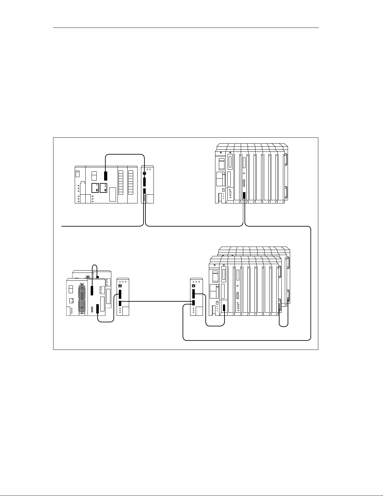
1.2 The CP 541 in the SIMATIC Environment
Incorporation in
SIMATIC
S5-100U
SINEC L2
Figure 1-1
shows the incorporation of the CP 541 in the SIMA
TIC environ
-
ment.
On account of the various communication modes, possible combinations of
communication modes and number of connectable programmable controllers,
Figure 1-1 is merely an example.
CP
541
S5-115U CP
5430
541
Figure 1-1 CP 541 in the SIMATIC Environment
For
CP 541 Emulates
SINEC L1
the connected programmable controller
figured SINEC L1 bus. The connected programmable controller is an
L1 slave.
1-4
CP
541
S5-115FS5-95F CP
, the CP 541 emulates a fully con
Communications
Processor CP
EW
A 4NEB 812 6188-02
-
541
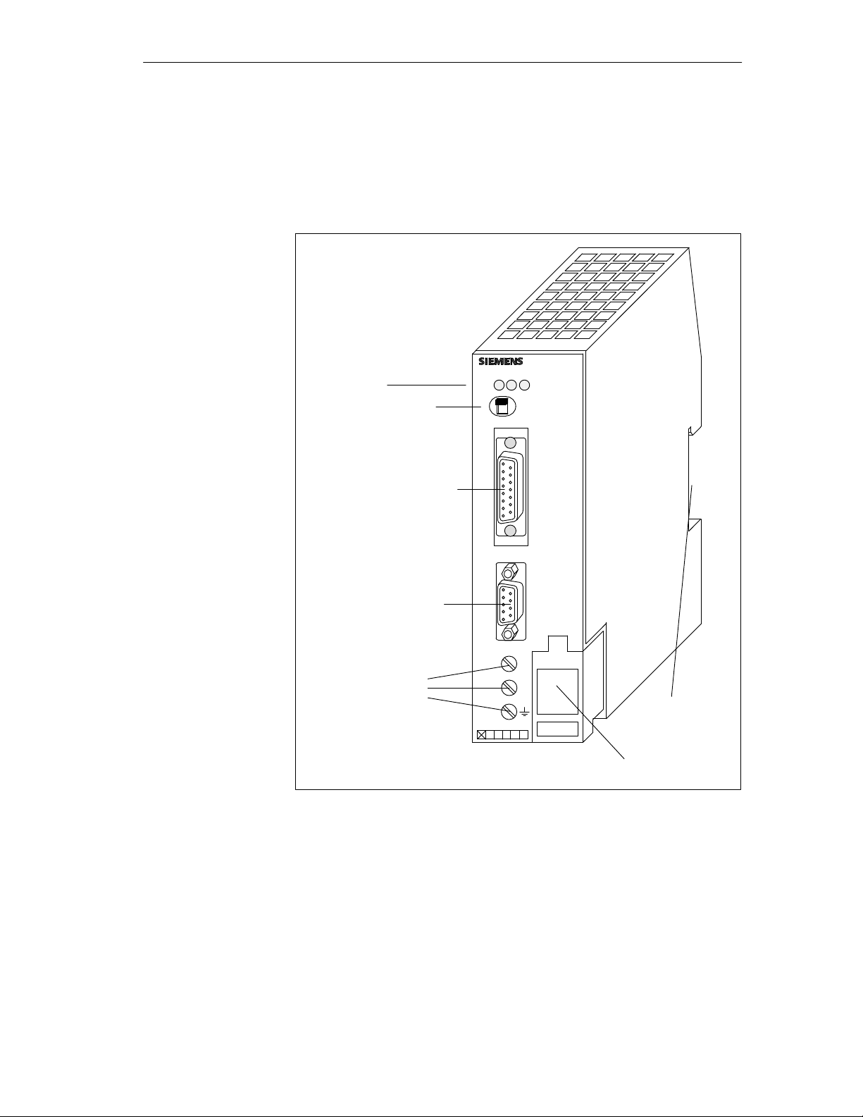
1.3 View of the CP 541
Overview
View
Figure 1-2
is a view of the CP 541
LED indicator
Mode switch
Connector for PG/PLC
Connector for SINEC L2
SIMATIC S5
ERR
RUN BF L2
RUN
STOP
0
PG/AG
SINEC L2
–
AG/AG
– DP
CP 541
Communications
EW
A 4NEB 812 6188-02
Processor CP
T
erminals for
24 V DC
power supply
Figure 1-2 View of the CP 541
541
24 V DC
6ES5 541-8AA1
12345 6
L+
M
Mount for
1
standard rail
Cover for
cable inlet
1-5

Overview
LED Indicators
The
CP 541 has three LEDs to indicate the operational state of the CP 541
and any errors.
Table 1-1 LED Indicators of the CP 541
LED Color Position Meaning
Mode Switch
Connectors and
Terminals
RUN Green Left Operational
ERR Red Middle
BF L2
Red Right
Error in CP 541 or at PG/PLC connection
Error at L2 connection or SINEC L2 not
state
yet activated
The CP 541 has a mode switch with three settings. The meanings of the dif
ferent settings are given in T
Table 1-2 Mode Switch of the CP 541
Switch
Setting
RUN
able 1-2.
Meaning
The CP 541 is in normal operation. Data will be ex
-
changed between the PLC and SINEC L2.
STOP Y
ou can assign parameters to the CP 541 with a PG
and read out the diagnostics block.
0
The CP 541 is switched of
f.
The CP 541 has various connectors and terminals; these are listed in
T
able 1-3.
-
1-6
Table 1-3 Connectors and Terminals of the CP 541
Designation Type Meaning
PG/PLC 15-pin
SINEC L2
- PLC-PLC
sub. D female with
slide latch
9-pin sub. D female with
screw-type connection
For PG cable or connecting
cable to PLC
For L2 bus connector
- DP
L+
Screw terminals
24
V DC power supply
M
Communications
Processor CP
EW
A 4NEB 812 6188-02
541

1.4 Suitable Programmable Controllers for the CP 541
SINEC L2
p
PLC-PLC
541
PLC-PLC
The
Introduction
summaries in T
of the SIMA
TIC S5 family which you can connect to the CP 541.
Also given are the communication modes you can install by means of CP 541
via SINEC L2 and the appropriate programmable controllers.
ables 1-4 and 1-5 indicate the programmable controllers
Overview
Stations via
Both
CP 541
Table 1-4 Connectable Programmable Controllers and Communication Modes; both Stations Connected to SI-
NEC L2 via CP 541
SINEC
L2
partner
When both SINEC L2 stations are connected via CP 541, T
the possible communication modes in relation to the appropriate program
mable controllers of the SIMA
TIC S5 family
CP
541 with
.
CP
able 1-4 shows
-
530 in
S5-90U
S5-115H
S5-135U
S5-155U
S5-155H
S5-115H
Connected
PLC
S5-95F
S5-95F S5-115F
PLC-PLC and safety-related
S5-95U
S5-100U
S5-115U
PLC-PLC
S5-115F
Broadcast and safety-related
broadcast
S5-90U
To
CP
541
S5-95U
S5-100U
S5-115U
CP
530
in
S5-115H
S5-135U
S5-155U
S5-155H
PLC-PLC
Broadcast
PLC-PLC
Broadcast
PLC-PLC
S5-115H PLC-PLC
Communications
EW
A 4NEB 812 6188-02
Processor CP
541
1-7
partner
S5-95U
CP
DP
Broadcast
DP
Overview
When
One Station via
CP 541
Table 1-5 Connectable Programmable Controllers and Communication Modes; one Station Connected to
SINEC L2 via CP 541
one SINEC L2 station is connected via CP 541, T
possible communication modes in relation to the appropriate programmable
controllers of the SIMA
TIC S5 family
.
able 1-5 shows the
Connected
PLC
To
541
CP
530
in
SINEC
L2
partner
S5-95U
and
SINEC L2
connec-
tion
S5-95F
S5-115F
S5-90U
S5-95U
S5-100U
S5-115U
PLC-PLC
Broadcast
S5-115H
S5-135U
S5-155U
S5-155H
S5-115H PLC-PLC
S5-95U as
DP master
IM 308B
IM308C
S5-115U
S5-115H
S5-135U
S5-155U
S5-155H
CP
5430
CP
5431
S5-115U
S5-115H
S5-135U
S5-155U
S5-155H
PLC-PLC
DP
Broadcast
PLC-PLC
DP
CP
342-5DPCP
S7-300 PG
Broadcast
5412
A2
DP
DP
Meanings of
Designations
Designation Meaning
PLC-PLC (see Section 2.1)
DP (see Section 2.2)
Broadcast (see Section 2.3)
Safety-related PLC-PLC (see
Section 5.1.1)
Safety-related broadcast (see
Section 5.1.2)
1-8
The abbreviations in T
The PLC-PLC connection serves to transmit messages between two
programmable controllers.
The DP connection serves to exchange messages with a higher
level DP master
Y
ou use a broadcast to transmit messages to all stations connected
to SINEC L2.
The safety-related PLC-PLC connection serves to transmit safety-
related messages between two failsafe programmable controllers.
Y
ou use safety-related broadcast to transmit safety-related mes
sages to all stations connected to SINEC L2.
ables 1-4 and 1-5 have the following meanings:
.
Communications
Processor CP
EW
A 4NEB 812 6188-02
-
-
541

Communication Modes
This
Introduction
chapter provides an overview of the communication modes you can use
via the CP 541.
2
Declarations
Acknowledgment
Summary of this
Chapter
The following two declarations apply to the entire Manual. Y
declarations to facilitate understanding of the various communication modes.
Node address
The node address is the address with which the programmable controller
connected to the CP 541 is accessed by it.
Station number
The station number is the number which distinguishes the various stations
on the SINEC L2. Each station number is uniquely assigned to a station.
The CP 541 always provides a positive acknowledgment to all messages it
receives from the programmable controller
Section Contents Page
2.1 PLC-PLC Connection 2-2
2.2 DP Connection 2-3
2.3 Broadcast via FDL Connection 2-4
.
ou require these
Communications
EW
A 4NEB 812 6188-02
Processor CP
541
2-1
Communication Modes
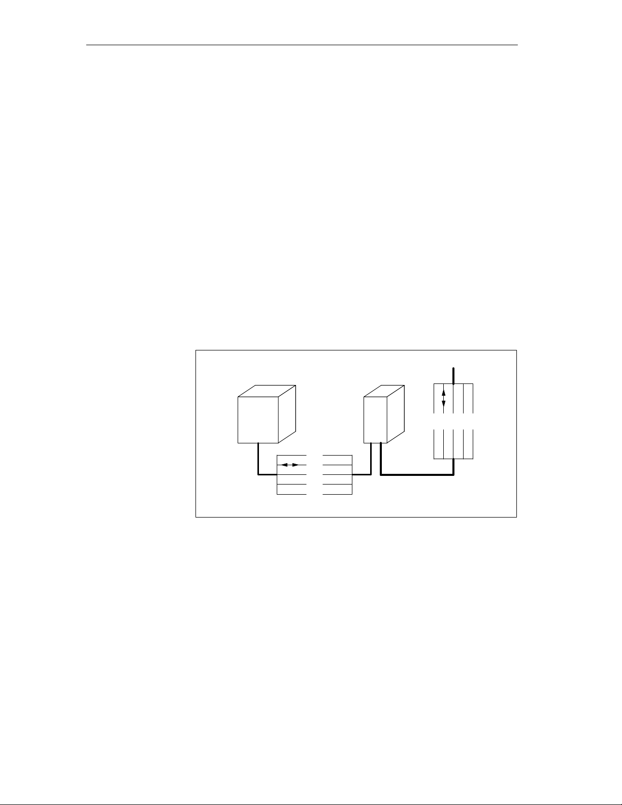
2.1 PLC-PLC Connection
The
Introduction
PLC-PLC connection serves for message-oriented communication be
tween two programmable controllers, without a detour via an additional sta
tion.
-
-
Message Length
Parameter
Assignment
Address
Conversion
Each message of the non-safety-related PLC-PLC connection can contain up
to 64 bytes of data.
If you install a PLC-PLC connection, you must parameterize the CP 541 as
an active station.
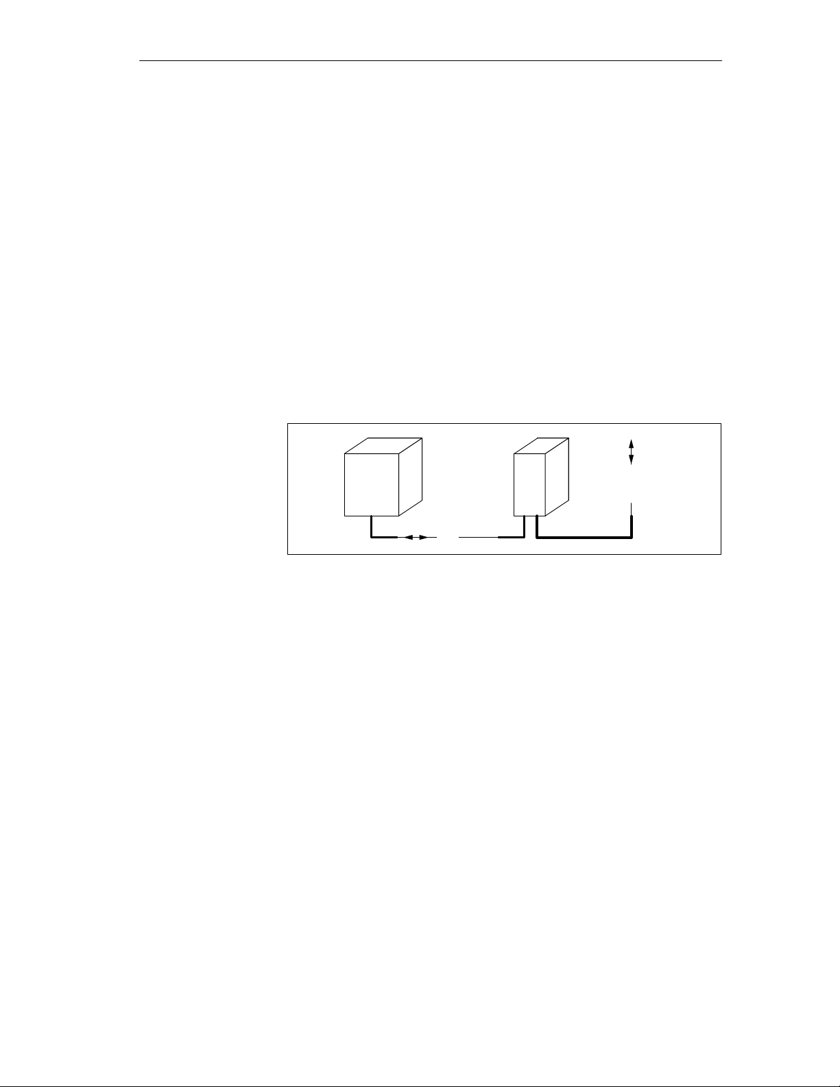
The node address specified in the programmable controller is converted by
the CP 541 to the station number and vice versa. Node address 1 is converted
to station number 1, node address 2 to station number 2, etc.
SINEC L2
PLC
1
2
3
30
CP
541
1 3032
Address Range
2-2
Figure 2-1 Address Conversion for PLC-PLC Connection
Node
addresses 1 to 30 are available in the connected programmable control
ler for the PLC-PLC connection.
Communications
Processor CP
EW
A 4NEB 812 6188-02
-
541
2.2 DP Connection
Introduction
The
tween a DP master and a DP slave.
Communication Modes
DP connection is data-oriented non-safety-related communication be
-
Message Length
Parameter
Assignment
Address
Conversion
Monitoring of the
Connected PLC
The DP connection can contain up to 16 words of data in each direction.
Y
ou install the DP connection in the connected programmable controller as a
connection with node address 0 (see Section 4.3).
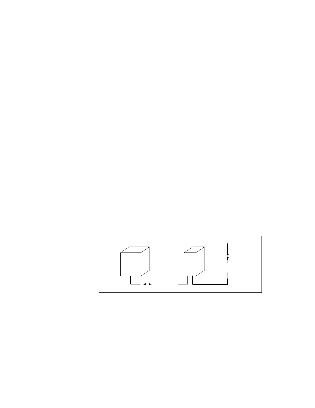
Node address 0 sent by the connected programmable controller is converted
to the DP master station number by the CP 541.
SINEC L2
PLC
0
Figure 2-2 Address Conversion for DP Connection
The
CP 541 monitors the DP connection to the programmable controller
CP
541
DP
master
.
Monitoring is active as soon as the CP 541 is accepted in the DP cycle and
the programmable controller has sent the first DP message.
DP Master
Monitoring
Note Relating to
the S5-1
Communications
EW
15F
A 4NEB 812 6188-02
Processor CP
When writing the user program in the programmable controller
, ensure that
cyclic DP data are presented within the response monitoring time (DPWD,
see Appendix C.5).
When the CP 541 no longer receives DP messages from the programmable
controller
, it emits a diagnosis to the DP master
.
As soon as the CP 541 is accepted in the DP cycle and the DP watchdog is
activated, the CP 541 monitors the connection to the DP master
.
If the DP connection to the DP master fails, the CP 541 informs the program
mable controller (see Section 6.4).
W
ith the S5-1
15F
, you can install either the DP connection or a non-safetyrelated PLC-PLC connection. Both connections are not simultaneously pos
sible because they both use node address 0.
541
-
-
2-3
Communication Modes
2.3 Broadcast via FDL Connection
The
Introduction
broadcast serves to transmit messages to all L2 stations which monitor
the SINEC L2 via FDL and the set SAP (service access point), and use the
SDN service.
Message Length
Implementation
Address
Conversion
Each broadcast message can contain up to 64 bytes of data.
The CP 541 converts a broadcast message from the connected programmable
controller to a multicast message on SINEC L2. A service access point (SAP)
is used for this conversion.
SAP
The CP 541 uses the default SAP 52 for broadcast. Y
SAP with parameter BSAP in frame COM of DB1.
The SAP number must be identical for all participating stations.
ou can change the
SDN
SDN (send data with no acknowledge) of the PROFIBUS protocol is used
for the broadcast.
Y
ou send the broadcast from the connected programmable controller to node
address 31. This node address is converted to station number 127 by the CP
541.
SINEC L2
FDL Connection
2-4
PLC
31
Figure 2-3 Address Conversion for Broadcast
You
can establish a point-to-point connection to any PROFIBUS station
which can exchange data via FDL (free layer 2). Y
CP
541
127
ou do this with a broadcast
and use the SAP to specify only one other station in SINEC L2 which can
receive the message.
If only the CP 541 and another station in SINEC L2 use this SAP
, you can
utilize this special form of broadcast to establish a connection to any other
non-Siemens device.
Communications
Processor CP
EW
A 4NEB 812 6188-02
541

Installing and Connecting the CP 541
When
Introduction
you have studied this chapter
start up the CP 541.
, you will be able to install, connect and
3
Installation of
Equipment
Working on
Cabinets
Summary of this
Chapter
Programmable controllers of the SIMA
series must be installed in electrical apparatus rooms or in enclosed housings,
such as metal or plastic cabinets.
Programmable controllers of the SIMA
S5-155U/H series must be installed in grounded, enclosed metal housings
such as cabinets.
T
o protect the modules from the dischar
sonnel must dischar
and control boxes.
Section Contents Page
3.1 Installing the CP 541 3-2
3.2 Connecting the CP 541 3-3
3.3 Starting up the CP 541 3-5
3.4 Operating States of the CP 541 3-6
ge themselves electrostatically before opening cabinets
TIC S5-90U, S5-95U/F and S5-100U
TIC S5-1
ge of static electricity
15U/H/F
, S5-135U and
, operating per
-
Communications
EW
A 4NEB 812 6188-02
Processor CP
541
3-1

Installing
and Connecting the CP 541
3.1 Installing the CP
The
Introduction
Mounting
Removal
CP 541 is mounted like a programmable controller of the SIMA
family
, for example the S5-95U or S5-100U, on a standard rail to
EN 50022-35
Mount the CP 541 on a standard rail. Y
Mount the CP 541 in the following order:
1.
Hook the CP 541 onto the rail.
2.
Swing the CP 541 down until the slide is heard to engage.
Remove the CP 541 in the following order:
1.
Switch of
2.
Remove the connecting cables.
3.
Use a screwdriver to push the slide down.
4.
Swing the CP 541 out of the rail.
541
15.
f the 24
TIC S5
ou need a free space of 46 mm.
VDC supply for the CP 541.
3-2
Communications
EW
A 4NEB 812 6188-02
Processor CP
541

Installing and Connecting the CP 541
3.2 Connecting the CP
Introduction
Supply
of Power
Connecting the
PLC to the CP 541
Connect
W
SIT
meeting the requirements given in Appendix A.
Connect the supply of power (24
CP 541. Ensure correct polarity
Connect the CP 541 and the programmable controller with the preassembled
connecting cable (see T
Observe correct connector assignments.
Table 3-1 Cable for Connecting the PLC and the CP 541
the CP 541 as follows.
e recommend the use of a SIT
OP power supply unit, you must use a safety-separated power supply
541
OP power supply unit. If you do not use a
VDC) to the three screw terminals on the
.
able 3-1).
Length Order
1 m
6ES5 735-8BB00
2.5 m 6ES5 735-8BC50
No.
Connecting the
Programmer
Connecting
SINEC L2
Components for
SINEC L2
Y
ou connect a programmer (PG) for parameter assignment or to evaluate the
diagnostics block, instead of the programmable controller
, to the PG/PLC
connector of the CP 541.
Connect SINEC L2 to the 9-pin subminiature D female connector of the CP
541. Use standard components of SINEC L2 (see the manual:
L2/L2FO Network Components
The components for SINEC L2 are given in T
Table 3-2 Components for SINEC L2
, 6GK1 970-5CA00-0AA).
able 3-2.
Name Order
SINEC
No.
Bus cable
Indoor
For burying in ground
Bus connector IP20
6XV1 830-0AH10
6XV1 830-3AH10
6ES5 762-2AA12
Communications
EW
A 4NEB 812 6188-02
Processor CP
541
3-3
Installing and Connecting the CP 541
Connecting the
Bus Cable
Electrical Separa
tion (Isolation)
Connect
with the bus connector
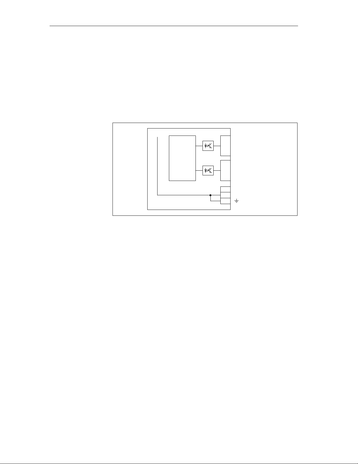
The PG/PLC interface and the SINEC L2 interface are safety-separated (iso
-
the bus cable to the bus connector, as explained in the instructions
.
lated) via optocouplers.
The reference potential and protective conductor terminal are internally con
nected.
PG/PLC
Logic
SINEC L2
24 V
M
Figure 3-1 Isolation of Terminals
-
-
Grounded
Configuration
Ungrounded
Configuration
Shielding
EMC Guidelines
As
a rule, you should use a grounded arrangement. This of
jection of interference. Any interference currents are dischar
to the protective conductor
Y
ou configure the CP 541 with a grounded reference potential by connecting
.
fers very high re
ged from the rail
the protective conductor terminal of the CP 541 to the protective conductor
Use a copper conductor with a cross-section of 2.5 mm.
T
o use the CP 541 in an ungrounded arrangement, you must fit the rail on
which the CP 541 is mounted, in an insulated arrangement. In the installed
state, the reference potential of the CP 541 is electrically connected to the
rail.
T
o dischar
protective conductor
V
alues for the network:
Parallel connection of R=100 kΩ und C=1
ge interference, you must connect the rail via an RC network to the
.
µF.
Connect the cable shields of the SINEC L2, and of the connecting cable be
tween CP 541 and the programmable controller
, to a shield bar at each end.
Further instructions for EMC-oriented configuration can be found in the
manual for the connected programmable controller
.
-
.
-
3-4
Communications
EW
A 4NEB 812 6188-02
Processor CP
541

3.3 Starting up the CP 541
Installing
and Connecting the CP 541
Startup
Step Action Meaning
1 Mount the CP 541 on the rail. See Section 3.1.
2 Make connections for a programmer, the
SINEC L2 and the power supply.
3 Switch the CP 541 to the STOP state. The CP 541 will be initialized (See Section 3.4.1).
4 Read DB1 into the programmer. DB1 is always present in the CP 541. After a reset, there is a
5 Make the necessary changes to DB1. You
6 T
7 Remove the programmer from the CP
8 Assign parameters to the connected PLC.
9 Connect the CP 541 to the PLC with the
10 Set the mode switch of the CP 541 to
ransfer the modified DB1 to the CP 541.
541.
connecting cable.
RUN.
Switch the connected PLC to RUN.
Proceed
in the following order for the first startup.
See Section 3.2
If you are restarting the CP 541 after an interval, connect the
PLC via the connecting cable instead of the programmer.
Skip Steps 4 to 7.
Programmer operation is only possible in the STOP state.
default DB1 in the CP 541.
have defined the parameters to be changed in Chapter 4.
For
normal operation, you must
PLC.
DB1 will be stored after a STOP-RUN transition.
The exchange of data between the connected PLC and SINEC L2 will begin.
a successful start and initialization of the interfaces, the
After
green RUN LED lights up. The CP 541 is in the RUN state.
provide the connection to the
Operation
Communications
EW
A 4NEB 812 6188-02
Processor CP
After
startup, the CP 541 executes the exchanging of data.
Detailed information on the operating states of the CP 541 can be found in
Section 3.4.
541
3-5

Installing and Connecting the CP 541
3.4 Operating
Introduction
Operating
States
States of the CP 541
You
can subdivide the operational behavior of the CP 541 into individual
operating states and their transitions, as explained in following.
W
e subdivide the operational behavior into the following operating states and
state transitions:
POWER ON
POWER ON is understood to mean the behavior when the CP 541 has
been switched on (from 0 to ST
restored.
ST
OP state
In the ST
OP state, you can use your PG to access both DBs in the CP 541.
START
The START serves to evaluate and store DB1 and activate the SINEC L2
interface.
RUN state
In the RUN state, the CP 541 executes the exchanging of data between
the connected programmable controller and SINEC L2.
OP), or when operating voltage has been
Summary of this
Section
Section Contents Page
3.4.1 POWER ON 3-7
3.4.2 STOP State 3-8
3.4.3 START 3-9
3.4.4 RUN State 3-10
3-6
Communications
EW
A 4NEB 812 6188-02
Processor CP
541
DB1 i
Y
EEPROM ok?
Installing and Connecting the CP 541
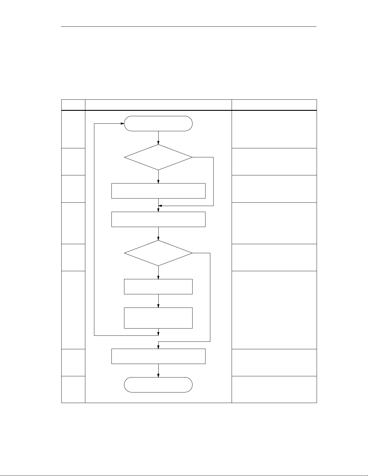
3.4.1 POWER ON
In
Power
On
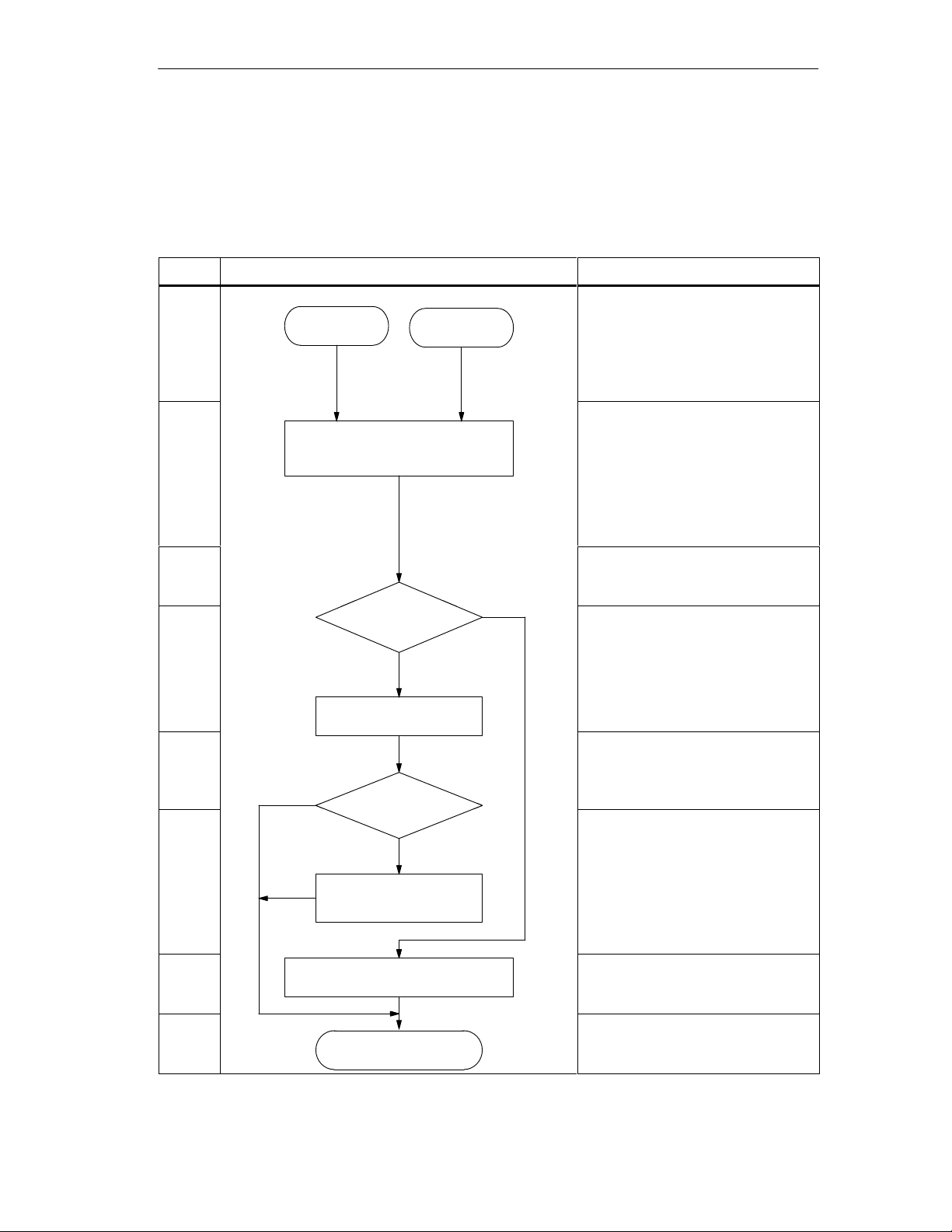
Step Flowchart Explanation
POWER ON, the CP 541 reacts as shown in the following flowchart.
1
Switch on
Power
restored
Whether or not you set the mode
switch from 0 to STOP, or whether
power is restored after a power fail
ure, the CP 541 reacts in the same
way.
2
CP
541 being initialized;
it executes an internal test.
In the initialization phase, all inter
nally stored interface data are reset
to reach a defined initial state.
-
An internal test is simultaneously
executed. During the test, the green
RUN LED flashes at 8 Hz.
3
The CP 541 checks whether a DB1
is present.
DB1 in
n
4
EEPROM?
es
If no DB1 is stored in the EE
-
PROM, it is subjected to a test of
No
approx. 6 s.
During the test, the green RUN
CP 541 tests EEPROM
5
LED flashes at 8 Hz.
W
ith the EEPROM test, the CP 541
tests the EEPROM for proper func
-
tioning.
No
6
Yes
If the EEPROM is OK, the CP 541
loads the default DB1 from the op
erating system.
-
7
8
Communications
EW
A 4NEB 812 6188-02
CP
Processor CP
CP
541 reads in
the default DB1
541 copies DB1 into RAM
STOP state
541
If an error occurs, DB2 can be read
out but the CP 541 cannot be
switched to the RUN state.
The CP 541 copies DB1 from the
EEPROM into the main memory
The CP 541 is in the ST
OP state.
.
The RUN LED flashes at 2 Hz.
3-7

Installing and Connecting the CP 541
3.4.2 STOP State
In
the ST
Meaning
nected programmable controller is not activated.
OP state, the CP 541 is initialized and the interface for the con
-
LED
RUN
Programmer
Operation
DB1
DB2
In the ST
In the ST
OP state, the RUN LED flashes at 2 Hz.
OP state, you can connect a programmer to the CP 541. The pro
-
grammer allows you to access the two data blocks DB1 and DB2.
The PG interface is activated in the ST
DB1 is the initialization block. Y
W
ith the entries in DB1, you af
OP state.
ou store the parameters for the CP 541 there.
fect the operational behavior and interchange
of data between the connected programmable controller and SINEC L2.
A full description of DB1 can be found in Appendix C.
DB2 is the diagnostics block. The CP 541 stores the determined diagnostic
data there. Y
ou can only read out DB2.
By means of the diagnostic data, you can establish whether there are errors in
the CP 541 or in the two communication interfaces.
A full description of DB2 can be found in Section 6.2.
3-8
Communications
EW
A 4NEB 812 6188-02
Processor CP
541
3.4.3 START
STOP
No
Installing
and Connecting the CP 541
START
The STAR
T is explained in the following flowchart.
Step Flowchart Explanation
1
STOP state
The CP 541 is in the ST
state.
RUN LED flashes at 2 Hz.
2
3
Mode switch set to RUN
4
CP
Setting
of mode
switch?
STOP
541 evaluates DB1
RUN
The CP 541 evaluates the set
ting of the mode switch.
Set the mode switch from ST
to RUN.
The CP 541 evaluates the pa
rameters in DB1 and checks
them for completeness and plau
sibility.
5
DB1 ok?
Yes
Is DB1 complete and are all pa
rameters in order?
OP
-
OP
-
-
-
No
6
CP
541 evaluates error
If an error is detected, the CP
541 evaluates the error and gen
erates an appropriate diagnostics
-
message in DB2.
CP 541 switches
error LED on
7
CP
541 copies DB1 into EEPROM
ally activated.
In the event of an error
541 remains in the ST
, the CP
OP state.
The CP 541 writes DB1 into the
The ERR error LED is addition
-
EEPROM.
8
RUN state
The CP 541 is in the RUN state.
The RUN LED lights up.
Communications
EW
A 4NEB 812 6188-02
Processor CP
541
3-9

Installing and Connecting the CP 541
3.4.4 RUN State
In
Meaning
the RUN state, both the PLC interface and the SINEC L2 interface are
ready to exchange data.
Operator inputs via the programmer are not possible in the RUN state.
Exchange of Data
Communication
The CP 541 transfers the data from the connected programmable controller to
SINEC L2 and vice versa.
A description of communication modes supported by the CP 541 can be
found in Chapter 2 and Section 5.1.
3-10
Communications
EW
A 4NEB 812 6188-02
Processor CP
541
 Loading...