

Page 1

Preface, Contents
SIMATIC
Point-to-point Communication
CP 440
Installation and Parameter
Assignment
Manual
Product Description
Basic Principles of Serial Data
Transmission
Commissioning the CP 440
Installing the CP 440
Configuring and
Parameterizing the CP 440
Communication Using Function
Blocks
Start-up Characteristics and
Operating Mode Transitions of
the CP 440
Diagnostics with the CP 440
Programming Example –
Standard Blocks
1
2
3
4
5
6
7
8
9
02/2000
A5E00057742
Edition 02
Appendices
Technical Specifications
Connecting Cables
Communication Matrix of the
Protocols
Accessories and Order
Numbers
Reference for SIMATIC S7
Index
A
B
C
D
E
Page 2

Safety Guidelines
This manual contains notices which you should observe to ensure your own personal safety, as well as to
protect the product and connected equipment. These notices are highlighted in the manual by a warning
triangle and are marked as follows according to the level of danger:
Danger
!
indicates that death, severe personal injury or substantial property damage will result if proper precautions are not taken.
Warning
!
indicates that death, severe personal injury or substantial property damage can result if proper precautions are not taken.
Caution
!
indicates that minor personal injury or property damage can result if proper precautions are not taken.
Note
draws your attention to particularly important information on the product, handling the product, or to a
particular part of the documentation.
Qualified Personnel
Only qualified personnel should be allowed to install and work on this equipment. Qualified persons are
defined as persons who are authorized to commission, to ground, and to tag circuits, equipment, and systems in accordance with established safety practices and standards.
Correct Usage
Note the following:
Warning
!
Trademarks
The reproduction, transmission or use of this document or its
contents is not permitted without express written authority.
Offenders will be liable for damages. All rights, including rights
created b y patent grant or registration of a utility model or design, are
reserved.
Siemens AG
Bereich Automatisierungs- und Antriebstechnik
Geschaeftsgebiet Industrie-Automatisierungssysteme
Postfach 4848, D- 90327 Nuernberg
Index-2
Siemens Aktiengesellschaft A5E00057742
This device and its components may only be used for the applications described in the catalog or the
technical descriptions, and only in connection with devices or components from other manufacturers
which have been approved or recommended by Siemens.
This product can only function correctly and safely if it is transported, stored, set up, and installed correctly, and operated and maintained as recommended.
SIMATIC, SIMATIC HMI and SIMATIC NET are registered trademarks of SIEMENS AG.
Some of other designations used in these documents are also registered trademarks; the owner’s rights
may be violated if they are used by third parties for their own purposes.
Disclaimer of LiabilityCopyright { Siemens AG 2000 All rights reserved
We have checked the contents of this manual for agreement with the
hardware and software described. Since deviations cannot be precluded entirely, we cannot guarantee full agreement. However, the
data in this manual are reviewed regularly and any necessary corrections included in subsequent editions. Suggestions for improvement are welcomed.
Siemens AG 2000
Point-to-point connection CP 341Installation and Parameter Assignment
Technical data subject to change.
C79000-G7000-C341-02
Page 3

Preface
Purpose
This manual explains how to establish and operate a point-to-point connection.
Contents of This Manual
The manual describes the hardware and software of the CP 440 communication
processor and its integration in an S7-400 programmable controller. It is divided up
into instruction-based chapters and a reference section (appendices).
The following subjects are covered:
• The basics of point-to-point communication with the CP 440
• Starting up the CP 440
• Installing the CP 440
• Communication with the CP 440
• Troubleshooting
• Application examples
• Properties and technical specifications
Scope of This Manual
This manual is valid for the following:
Product Order Number As of Version
CP 440 with the
X27 RS 422/485 interface
Note
The description of the CP 440 communication processor in this manual were
correct at the time of publication. We reserve the right to describe modifications to
the functionality of the modules in a separate Product Information.
Point-to-point connection CP 440 Installation and Parameter Assignment
A5E00057742-02
6ES7 440-1CS00-0YE0 01
iii
Page 4

Preface
Structure of This Manual
To help you to quickly find the information you require, this manual offers the
following:
• You will find a full table of contents at the beginning of the manual.
• Finally, a comprehensive index allows quick access to information on specific
subjects.
iv
Point-to-point connection CP 440 Installation and Parameter Assignment
A5E00057742-02
Page 5

Other Manuals Required
Appendix E contains a list of the other manuals on the subject of the S7-400 that
you will require in order to put your system into operation.
Electronic Manuals
The entire set of SIMATIC S7 documentation is available on CD-ROM.
Standards, Certificates and Approvals
The CP 440 communication processor meets the requirements and criteria of
IEC 1131, Part 2 and the requirements for CE marking. The CP 440 has CSA
certification, UL recognition and FM approval.
Recycling and Disposal
The CP 440 is an environment-friendly product. It is exceptional for the following:
Preface
• Housing plastic with halogen-free flame protection and is highly resistant to fire
• Laser inscriptions (i.e. no labels)
• Plastics identification in accordance with DIN 54840
• Fewer materials used due to size reduction; fewer parts due to integration in
ASICs
The CP 440 is suitable for recycling on account of the low level of contaminants in
its components.
For further information about environment-friendly recycling and the procedure for
disposing of your old equipment, please contact:
Siemens Aktiengesellschaft
Anlagenbau und Technische Dienstleistungen
ATD TD 3 Kreislaufwirtschaft
Postfach 32 40
D-91050 Erlangen, Germany
Phone: + 49 91 31/7-3 36 98
Fax: + 49 91 31/7-2 66 43
The people there will adapt their advice to suit your situation and provide a
comprehensive and flexible recycling and disposal system at a fixed price. After
disposal you will receive information giving you a breakdown of the relevant
material fractions and the associated documents as evidence of the materials
involved.
Point-to-point connection CP 440 Installation and Parameter Assignment
A5E00057742-02
v
Page 6

Preface
Additional Assistance
Please contact your local Siemens representative if you have any queries about
the products described in this manual. A list of Siemens representatives worldwide
is contained, for example, in the “Siemens Worldwide” Appendix of the manual
S7-400 Programmable Controller, Hardware and Installation
If you have any questions or suggestions concerning this manual, please fill out the
form at the back and return it to the specified address. Please feel free to enter
your personal assessment of the manual in the form provided.
We offer a range of courses to help get you started with the SIMATIC S7
programmable controller. Please contact your local training center or the central
training center in Nuremberg, D-90027 Germany (tel. +49 911 895 3200).
Constantly Updated Information
You can obtain constantly updated information on the SIMATIC products on the
Internet at http://www.ad.siemens.de
.
In addition, SIMATIC Customer Support provides you with up-to-date information
and downloads that can be useful to you when using SIMATIC products:
• On the Internet at http://www.ad.siemens.de/simatic-cs
• Via the SIMATIC Customer Support Mailbox (German) at 49 (911) 895-7100
or the SIMATIC Customer Support BBS (English).
The mailbox is best accessed with a modem up to V.34 (28.8 kbps) parameterized
as follows: 8, N, 1, ANSI, or via ISDN (x.75, 64 kbits).
You can contact SIMATIC Customer Support by phone at 49 (911) 895-7000 or
by fax at 49 (911) 895-7002. You can send questions by e-mail on the Internet or
to the above-mentioned mailbox.
vi
Point-to-point connection CP 440 Installation and Parameter Assignment
A5E00057742-02
Page 7

Contents
1 Product Description 1-1. . . . . . . . . . . . . . . . . . . . . . . . . . . . . . . . . . . . . . . . . . . . . . . . . . . .
1.1 Applications of the CP 440 1-2. . . . . . . . . . . . . . . . . . . . . . . . . . . . . . . . . . . . . . . .
1.2 Components Required for a Point-to-Point Connection with the CP 440 1-3.
1.3 Design of the CP 440 1-6. . . . . . . . . . . . . . . . . . . . . . . . . . . . . . . . . . . . . . . . . . . .
1.4 Features of the X27 (RS 422/485) Interface 1-8. . . . . . . . . . . . . . . . . . . . . . . . .
1.4.1 Cables for Connecting the CP 440 to a Communication Partner 1-8. . . . . . . .
2 Basic Principles of Serial Data Transmission 2-1. . . . . . . . . . . . . . . . . . . . . . . . . . . . .
2.1 Serial Transmission of a Character 2-2. . . . . . . . . . . . . . . . . . . . . . . . . . . . . . . .
2.2 Transmission Procedure with a Point-to-Point Connection 2-6. . . . . . . . . . . . .
2.2.1 ISO 7-Layer Reference Model for Data Transmission 2-6. . . . . . . . . . . . . . . . .
2.2.2 Data Transmission with the ASCII Driver 2-11. . . . . . . . . . . . . . . . . . . . . . . . . . .
2.2.3 Data Transmission with the 3964(R) Procedure 2-24. . . . . . . . . . . . . . . . . . . . . .
3 Commissioning the CP 440 3-1. . . . . . . . . . . . . . . . . . . . . . . . . . . . . . . . . . . . . . . . . . . . . .
3.1 Sequence of Steps to Be Taken 3-2. . . . . . . . . . . . . . . . . . . . . . . . . . . . . . . . . . .
3.2 Commissioning the Physical Interface 3-4. . . . . . . . . . . . . . . . . . . . . . . . . . . . . .
4 Installing the CP 440 4-1. . . . . . . . . . . . . . . . . . . . . . . . . . . . . . . . . . . . . . . . . . . . . . . . . . . .
4.1 CP 440 Slots 4-2. . . . . . . . . . . . . . . . . . . . . . . . . . . . . . . . . . . . . . . . . . . . . . . . . . .
4.2 Installing and Removing the CP 440 4-3. . . . . . . . . . . . . . . . . . . . . . . . . . . . . . .
4.3 Installation Guidelines 4-4. . . . . . . . . . . . . . . . . . . . . . . . . . . . . . . . . . . . . . . . . . . .
5 Configuring and Parameterizing the CP 440 5-1. . . . . . . . . . . . . . . . . . . . . . . . . . . . . .
5.1 Configuring the CP 440 5-2. . . . . . . . . . . . . . . . . . . . . . . . . . . . . . . . . . . . . . . . . .
5.2 Parameterizing the Communication Protocols 5-3. . . . . . . . . . . . . . . . . . . . . . .
5.3 Parameterization Data 5-4. . . . . . . . . . . . . . . . . . . . . . . . . . . . . . . . . . . . . . . . . . .
5.3.1 Basic Parameters of the CP 440 5-4. . . . . . . . . . . . . . . . . . . . . . . . . . . . . . . . . .
5.3.2 Parameterization Data of the ASCII Driver 5-6. . . . . . . . . . . . . . . . . . . . . . . . . .
5.3.3 Parameterization Data of the 3964(R) Procedure 5-14. . . . . . . . . . . . . . . . . . . .
5.4 Management of the Parameter Data 5-20. . . . . . . . . . . . . . . . . . . . . . . . . . . . . . .
5.5 Uploading Firmware Updates 5-21. . . . . . . . . . . . . . . . . . . . . . . . . . . . . . . . . . . . .
Point-to-point connection CP 440 Installation and Parameter Assignment
A5E00057742-02
vii
Page 8

Contents
6 Communication Using Function Blocks 6-1. . . . . . . . . . . . . . . . . . . . . . . . . . . . . . . . . .
6.1 Communication Using Function Blocks 6-2. . . . . . . . . . . . . . . . . . . . . . . . . . . . .
6.2 Overview of the Function Blocks 6-3. . . . . . . . . . . . . . . . . . . . . . . . . . . . . . . . . .
6.3 Notes on Program Structure 6-4. . . . . . . . . . . . . . . . . . . . . . . . . . . . . . . . . . . . . .
6.4 Using the Function Blocks 6-5. . . . . . . . . . . . . . . . . . . . . . . . . . . . . . . . . . . . . . . .
6.4.1 The S7 Transmits Data to a Communication Partner,
10 SEND_440 FB 6-6. . . . . . . . . . . . . . . . . . . . . . . . . . . . . . . . . . . . . . . . . . . . . . .
6.4.2 S7 Receives Data from a Communication Partner, 9 RECV_440 FB 6-10. . . .
6.4.3 Deleting the Receive Buffer (11 “RES_RECV” FB) 6-14. . . . . . . . . . . . . . . . . . .
6.5 Programming the Function Blocks 6-18. . . . . . . . . . . . . . . . . . . . . . . . . . . . . . . . .
6.5.1 General Information on Data Block Assignment 6-18. . . . . . . . . . . . . . . . . . . . .
6.5.2 Supplying the Block Parameters 6-19. . . . . . . . . . . . . . . . . . . . . . . . . . . . . . . . . . .
6.6 General Information on Program Processing 6-23. . . . . . . . . . . . . . . . . . . . . . . .
6.7 Technical Specifications of the Function Blocks 6-24. . . . . . . . . . . . . . . . . . . . . .
7 Startup Characteristics and Operating Mode Transitions of the CP 440 7-1. . . . .
7.1 Operating Modes of the CP 440 7-2. . . . . . . . . . . . . . . . . . . . . . . . . . . . . . . . . . .
7.2 Startup Characteristics of the CP 440 7-2. . . . . . . . . . . . . . . . . . . . . . . . . . . . . .
7.3 Behavior of the CP 440 During Operating Mode Transitions of the CPU 7-3.
7.4 Behavior of the Sender Line Drivers of the Serial Interface
During Particular Operating Modes of the CP 440 7-4. . . . . . . . . . . . . . . . . . . .
8 Diagnostics with the CP 440 8-1. . . . . . . . . . . . . . . . . . . . . . . . . . . . . . . . . . . . . . . . . . . . .
8.1 Diagnostic functions of the CP 440 8-2. . . . . . . . . . . . . . . . . . . . . . . . . . . . . . . .
8.2 Diagnosis via the Display Elements of the CP 440 8-3. . . . . . . . . . . . . . . . . . .
8.3 Diagnostic Messages of the Function Blocks 8-5. . . . . . . . . . . . . . . . . . . . . . . .
8.4 Diagnostics Using the Diagnostic Buffer of the CP 440 8-14. . . . . . . . . . . . . . .
9 Programming Example – Standard Blocks 9-1. . . . . . . . . . . . . . . . . . . . . . . . . . . . . . . .
9.1 General 9-2. . . . . . . . . . . . . . . . . . . . . . . . . . . . . . . . . . . . . . . . . . . . . . . . . . . . . . . .
9.2 Device Configuration 9-2. . . . . . . . . . . . . . . . . . . . . . . . . . . . . . . . . . . . . . . . . . . . .
9.3 Settings 9-3. . . . . . . . . . . . . . . . . . . . . . . . . . . . . . . . . . . . . . . . . . . . . . . . . . . . . . . .
9.4 Blocks Used 9-4. . . . . . . . . . . . . . . . . . . . . . . . . . . . . . . . . . . . . . . . . . . . . . . . . . . .
9.5 Installation, Error Messages 9-7. . . . . . . . . . . . . . . . . . . . . . . . . . . . . . . . . . . . . .
9.6 Activation, Startup Program and Cyclic Program 9-8. . . . . . . . . . . . . . . . . . . . .
9.6.1 “CP440 SEND RECV” Program Example 9-8. . . . . . . . . . . . . . . . . . . . . . . . . . .
9.6.2 “CP440 1 CYC” Program Example 9-9. . . . . . . . . . . . . . . . . . . . . . . . . . . . . . . . .
9.6.3 “CP440 ASCII BCC” Program Example 9-10. . . . . . . . . . . . . . . . . . . . . . . . . . . . .
9.6.4 “CP440 MASTER” Program Example 9-12. . . . . . . . . . . . . . . . . . . . . . . . . . . . . .
9.6.5 “CP440 SLAVE” Program Example 9-12. . . . . . . . . . . . . . . . . . . . . . . . . . . . . . . .
viii
Point-to-point connection CP 440 Installation and Parameter Assignment
A5E00057742-02
Page 9

Contents
A Technical Specifications A-1. . . . . . . . . . . . . . . . . . . . . . . . . . . . . . . . . . . . . . . . . . . . . . . .
A.1 Technical Specifications of the CP 440 A-2. . . . . . . . . . . . . . . . . . . . . . . . . . . . .
A.2 Transmission Times A-5. . . . . . . . . . . . . . . . . . . . . . . . . . . . . . . . . . . . . . . . . . . . .
B Connecting Cables B-1. . . . . . . . . . . . . . . . . . . . . . . . . . . . . . . . . . . . . . . . . . . . . . . . . . . . .
B.1 X27 (RS 422/485) Interface of the CP 440 B-2. . . . . . . . . . . . . . . . . . . . . . . . . .
C Communication Matrix of the Protocols C-1. . . . . . . . . . . . . . . . . . . . . . . . . . . . . . . . . .
D Accessories and Order Numbers D-1. . . . . . . . . . . . . . . . . . . . . . . . . . . . . . . . . . . . . . . .
E Reference for SIMATIC S7 E-1. . . . . . . . . . . . . . . . . . . . . . . . . . . . . . . . . . . . . . . . . . . . . . .
Index Index-1. . . . . . . . . . . . . . . . . . . . . . . . . . . . . . . . . . . . . . . . . . . . . . . . . . . . . . . . . . . . . . . .
Point-to-point connection CP 440 Installation and Parameter Assignment
A5E00057742-02
ix
Page 10

Contents
x
Point-to-point connection CP 440 Installation and Parameter Assignment
A5E00057742-02
Page 11

Product Description
In Section You Will Find on Page
1.1 Applications of the CP 440 1-2
1.2 Components Required for a Point-to-Point Connection with the
CP 440
1.3 Design of the CP 440 1-6
1.4 Properties of the X27 (RS 422/485) Interface 1-8
1
1-3
Point-to-point connection CP 440 Installation and Parameter Assignment
A5E00057742-02
1-1
Page 12

Product Description
1.1 Applications of the CP 440
The CP 440 communication processor enables you to exchange data between
programmable controllers or computers by means of a point-to-point connection.
The CP 440 is designed to transfer short, fast frames.
The following are typically connected to it:
• Scanners, barcode readers
• Sensors
• Weighing scales
Functionality of the CP 440
The CP 440 communication processor provides the following functionality:
• An integrated MPI (Multipoint) X27 (RS422/485) interface
• A maximum transmission length of 200 bytes
• A transmission rate of up to 115.2 kbps, full-duplex
• Integration of the most important transmission protocols in the module firmware
– ASCII driver
– 3964(R) procedure
• Customization of the transmission protocols by means of parameter assignment
with the
CP 440: Point-to-Point Communication, Parameter Assignment
parameterization interface.
Applications of the CP 440
The CP 440 communication processor allows point-to-point communication with
SIMATIC modules and with non-Siemens products. The SIMATIC modules that
can be connected are listed in Appendix C.
Functions Supported by the Interfaces
Table 1-1 Functions of the CP 440
Function
3964(R) procedure Yes No
ASCII driver Yes Yes
• XON/XOFF flow control Yes No
CP 440
RS 422* RS 485*
1-2
* The RS 422 and RS 485 are distinguished by means of parameterization.
Point-to-point connection CP 440 Installation and Parameter Assignment
A5E00057742-02
Page 13
Product Description
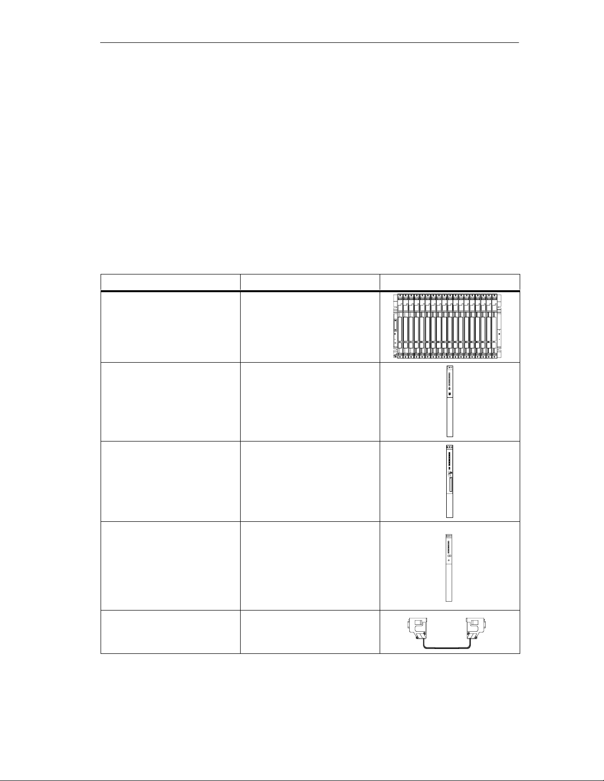
1.2 Components Required for a Point-to-Point Connection with the CP 440
To establish a point-to-point connection between the CP 440 communication
processor and a communication partner, you require certain hardware and
software components.
Hardware Components
The following table lists the hardware components required for establishing a
point-to-point connection with the CP 440.
Table 1-2 Hardware Components for a Point-to-Point Connection with the CP 440
Components
Rack ... provides the mechanical and
electrical connections of the
S7-400.
Power supply module (PS) ... converts the line voltage
(120/230 VAC or 24 VDC) into
the operating voltage of 24 V and
5 VDC required to supply the
S7-400.
CPU
The CPUs with which the CP 440
cannot be used are listed in
Tables 1-5 and 1-4.
Accessories: Memory card
Backup battery
CP 440 communication
processor
... executes the user program;
communicates via the MPI
interface with other CPUs or with
a programming device.
... communicates via the interface
with one or more communication
partners.
Function Diagram
Standard connecting cable ... connects the CP 440
communication processor to the
communication partner.
Point-to-point connection CP 440 Installation and Parameter Assignment
A5E00057742-02
1-3
Page 14
Product Description
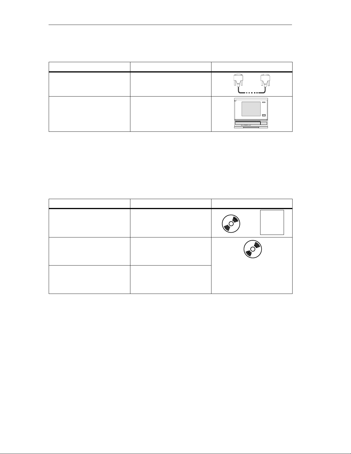
Table 1-2 Hardware Components for a Point-to-Point Connection with the CP 440, continued
Components DiagramFunction
Programming device cable ... connects a CPU to a
programming device/PC.
Programming device or PC ... communicates with the CPU of
the S7-400.
Software Components
The following table lists the software components required for establishing a
point-to-point connection with the CP 440.
Table 1-3 Software Components for a Point-to-Point Connection with the CP 440
Components
STEP 7 software package,
as of version 4.0.2
CP 440: Point-to-Point
Communication, Parameter
Assignment
interface, Version 5.1
Function blocks (FBs) with
programming examples
Parameterization
... configures, parameterizes,
programs and tests the S7-400.
... parameterizes the interfaces of
the CP 440.
... control communication
between the CPU and the
CP 440.
Function Diagram
+
License
1-4
Point-to-point connection CP 440 Installation and Parameter Assignment
A5E00057742-02
Page 15

Product Description
CPU Versions
The CP 440 can be operated with all CPU versions except the CPUs listed in the
tables below:
Table 1-4 CPU Versions with Which the CP 440 Can Be Used as of the Version Indicated
CPU MLFB
CPU 412-1 6ES7 412-1XF01-0AB0, Release 5
CPU 413-1 6ES7 413-1XG01-0AB0, Release 5
CPU 413-2 6ES7 413-2XG01-0AB0, Release 5
CPU 414-1 6ES7 414-1XG01-0AB0, Release 5
CPU 414-2 with 128k 6ES7 414-2XG01-0AB0, Release 5
CPU 414-2 with 348k 6ES7 414-2XJ00-0AB0, Release 7
CPU 416-1 6ES7 416-1XJ01-0AB0, Release 5
CPU 416-2 with 0.8 M 6ES7 416-2XK00-0AB0, Release 7
CPU 416-2 with 1.6 M 6ES7 416-2XL00-0AB0, Release 7
CPU 416-2 DP ISA Lite
6ES7 616-2PK00-0AB4, Release 3
CPU 416-2 DP ISA
CPU 412-2 DP PCI
CPU 416-2 DP PCI
Table 1-5 CPU Versions with Which the CP 440 Cannot be Used
CPU MLFB
CPU 412-1 6ES7 412-1XF00-0AB0
CPU 413-1 6ES7 413-1XG00-0AB0
CPU 413-2 6ES7 413-2XG00-0AB0
CPU 414-1 6ES7 414-1XG00-0AB0
CPU 414-2 with 128k 6ES7 414-2XG00-0AB0
CPU 416-1 6ES7 416-1XJ00-0AB0
Point-to-point connection CP 440 Installation and Parameter Assignment
A5E00057742-02
1-5
Page 16
Product Description
1.3 Design of the CP 440
Interface
The CP 440 communication processor is supplied with an integrated serial X27
(RS422/485) interface.
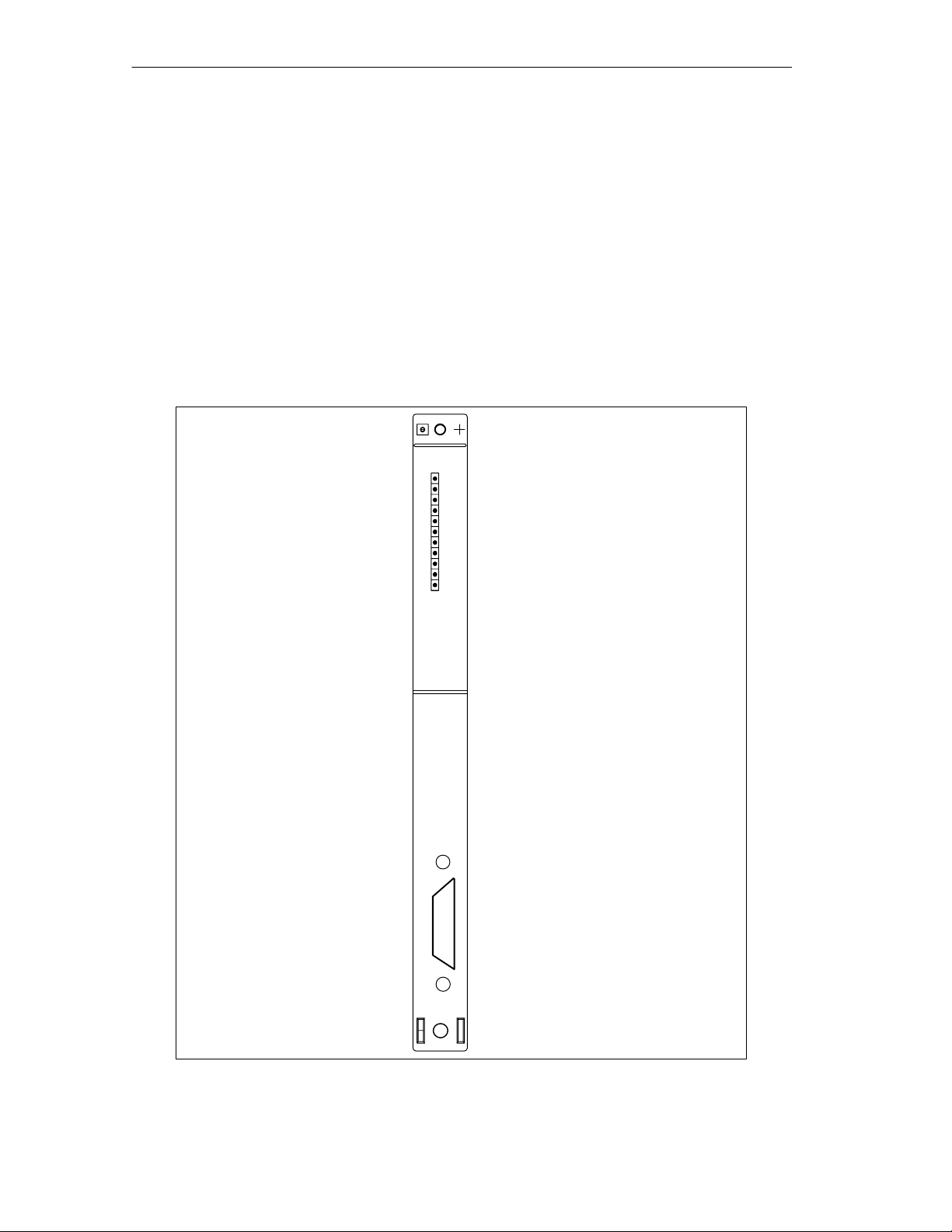
Arrangement of the Controls and Indicators
Fig. 1-1 shows the arrangement of the controls and indicators on the front panel of
the CP 440 communication processor.
CP 440
440 – 1CS00 – 0YE0
V1.0.0
INTF
EXTF
FAULT
TxD
RxD
CP 440
X 2
3 4
Firmware version
INTF
EXTF
FAULT
TxD
RxD
Integrated
X27
(RS422/485)
interface
1-6
Figure 1-1 Arrangement of the Controls and Indicators on the CP 440 Communication
Processor
Point-to-point connection CP 440 Installation and Parameter Assignment
A5E00057742-02
Page 17

LEDs
Interface
Product Description
The following LEDs are located on the front panel of the CP 440:
• INTF (red) Indicates an internal fault
• EXFT (red) Indicates an external fault
• FAULT (red) Fault LED for interface
• TXD (green) interface sends
• RXD (green) interface receives
The operating modes and faults and errors indicated by these LEDs are described
in Section 8.2. Section 5.5 contains information on the LEDs that come on when
you download firmware updates.
For a detailed description of the interface, see Section 1.4.
Base Connector for the S7 Backplane Bus
On the back panel of the CP 440 you will find the base connector for the S7-400
backplane bus.
The S7-400 backplane bus is the serial data bus via which the CP 440
communicates with the modules of the programmable controller.
Point-to-point connection CP 440 Installation and Parameter Assignment
A5E00057742-02
1-7
Page 18

Product Description
1.4 Features of the X27 (RS 422/485) Interface
Definition
The X27 (RS 422/485) interface is a differential voltage interface used for serial
data transmission in compliance with the X27 standard.
Features
The X27 (RS 422/485) interface has the following features and meets the following
requirements:
• Type: differential voltage interface
• Front connector: 15-pin sub D female with screw fixing
• Max. transmission rate: 115.2 kbps
• Max. cable length: 1200 m at 19200 bps
*
• Standard: DIN 66259 Parts 1 and 3,
EIA-RS 422/485, CCITT V.11
• Degree of protection: IP00
Note
The X27 (RS 422/485) interface can only be run in 4-wire mode with the 3964(R)
protocol.
1.4.1 Cables for Connecting the CP 440 to a Communication Partner
Standard Connecting Cables
For point-to-point connection between the CP 440 and a communication partner,
Siemens offers standard connecting cables in various lengths.
The lengths and order numbers of these cables are listed in Appendix D.
Constructing Your Own Connecting Cables
If you make your own connecting cables, there are some points you must be
aware of. These are described in Appendix B, along with wiring plans and the pin
allocation for the sub D male connector.
* To find out which cable types you can use, see Appendix B.
Point-to-point connection CP 440 Installation and Parameter Assignment
1-8
A5E00057742-02
Page 19

Basic Principles of Serial Data Transmission
In Section You Will Find on Page
2.1 Serial Transmission of a Character 2-2
2.2 Transmission Procedure with a Point-to-Point Connection 2-6
2
Point-to-point connection CP 440 Installation and Parameter Assignment
A5E00057742-02
2-1
Page 20

Basic Principles of Serial Data Transmission
2.1 Serial Transmission of a Character
There are various networking alternatives for the transfer of data between two or
more communication partners. The simplest form of data interchange is via a
point-to-point connection between two communication partners.
Point-to-Point Connection
In a point-to-point connection the CP 440 communication processor forms the
interface between a programmable controller and a communication partner. In a
point-to-point connection with the CP 440, the data is transferred serially.
Serial Data Transmission
In serial transmission, the individual bits of each byte of information are transmitted
one after the other in a fixed order.
Drivers for Bidirectional Data Traffic
The CP 440 executes data transfer with communication partners independently via
the serial interface. The CP 440 is equipped with two different drivers for this
purpose.
Bidirectional Data Traffic:
• ASCII driver
• 3964(R) procedure
The CP 440 executes data transfer via the serial interface depending on the
selected driver.
2-2
Point-to-point connection CP 440 Installation and Parameter Assignment
A5E00057742-02
Page 21

Bidirectional Data Traffic - Operating Modes
The CP 440 has two operating modes for bidirectional data traffic:
• Half-duplex operation (3964(R) procedure, ASCII driver)
Data is exchanged between the communication partners but only in one
direction at a time. In half-duplex operation, therefore, at any one time, data is
being either sent or received. The exception to this may be individual control
characters for data flow control (e.g. XON/XOFF), which can also be sent while
data is being received or received while data is being sent.
• Full-duplex operation (ASCII driver)
Data is exchanged between two or more communication partners in both
directions simultaneously. In full-duplex operation, therefore, data can be sent
and received at the same time. Each communication partner must be able to
send and receive simultaneously.
Only half-duplex mode can be used with an RS 485 (2-wire) setting.
Basic Principles of Serial Data Transmission
Asynchronous Data Transmission
With the CP 440, serial transmission takes place asynchronously. What is known
as timebase synchronization (a fixed timing code used in the transmission of a
fixed character string) is only upheld during transmission of a character. Each
character to be sent is preceded by a synchronization impulse, or start bit. The end
of the character transmission is signaled by the stop bit.
Declarations
As well as the start and stop bits, further declarations must be made between the
two communication partners before serial transmission can take place. These
include:
• Transmission rate (baud rate)
• Character and acknowledgment delay times
• Parity
• Number of data bits
• Number of stop bits
Section 2.2 describes the importance of the declarations in the various
transmission procedures, and how they are parameterized.
Point-to-point connection CP 440 Installation and Parameter Assignment
A5E00057742-02
2-3
Page 22
Basic Principles of Serial Data Transmission
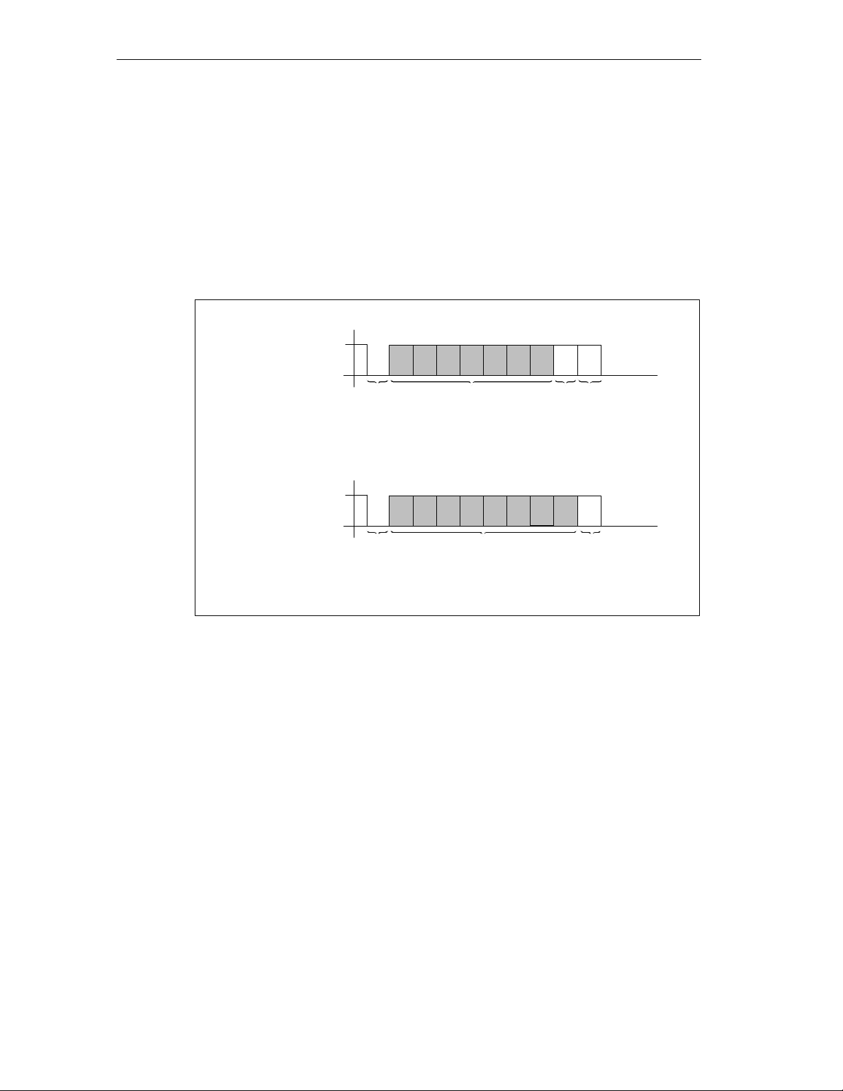
Character Frames
Data is transmitted between the CP 440 and a communication partner via the
serial interface in a character frame. Two data formats are available for each
character frame. 7 data bits without a parity bit are not supported. You can
parameterize the format for data transmission with the
Communication, Parameter Assignment
By way of example, the figure below shows the two data formats of the 10-bit
character frame.
7 data bits, 1 start bit, 7 data bits, 1 parity bit, 1 stop bit
Signal state “1”
1
Signal state “0”
CP 440: Point-to-Point
parameterization interface.
289
10
1 start bit
8 data bits: 1 start bit, 8 data bits, 1 stop bit
Signal state “1”
1
Signal state “0”
1 start bit
Figure 2-1 10-Bit Character Frame
7 data bits
2 109
8 data bits
1 stop bit
1 parity bit
1 stop bit
2-4
Point-to-point connection CP 440 Installation and Parameter Assignment
A5E00057742-02
Page 23
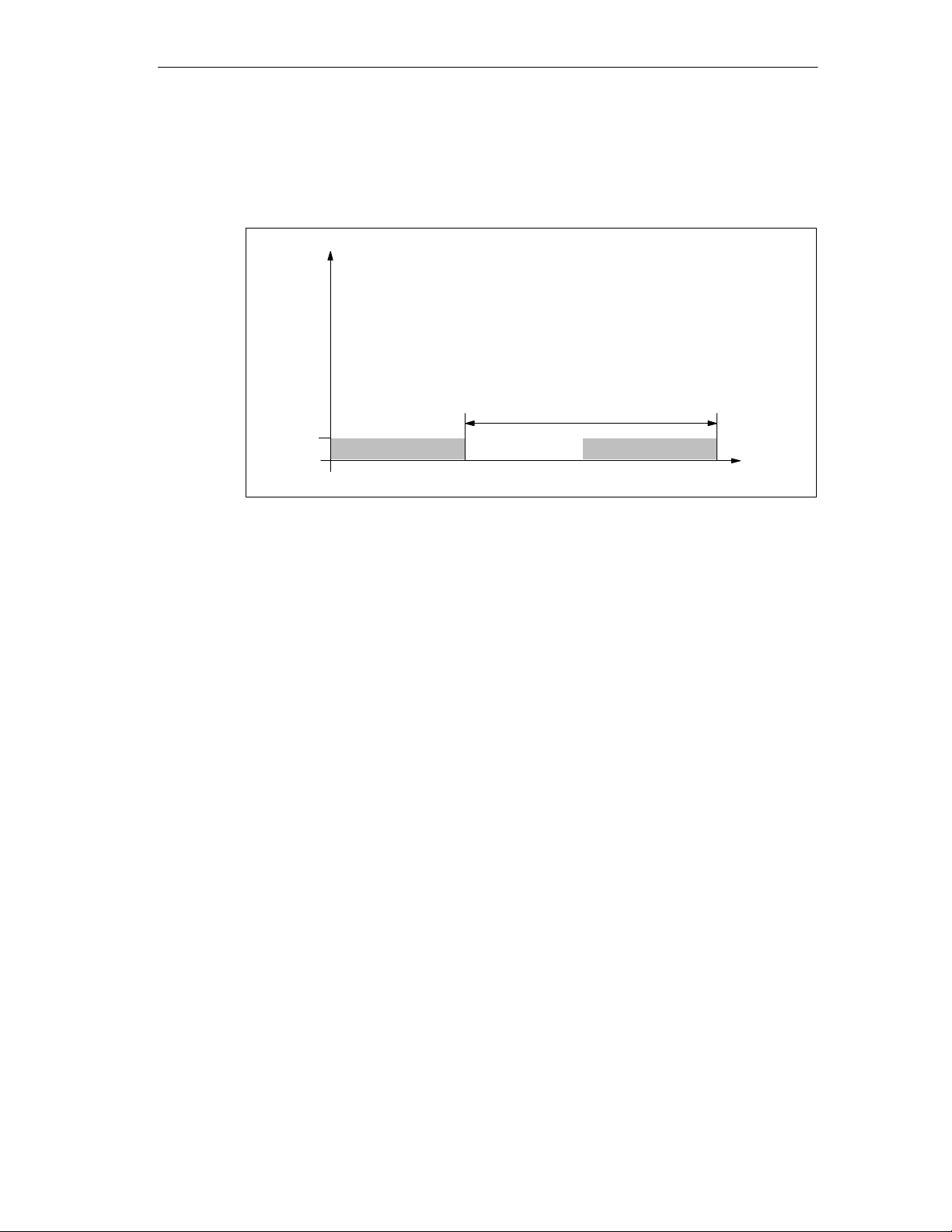
Character Delay Time
The figure below shows the maximum time permitted between two characters
received within a message frame. This is known as the character delay time.
Signal
1
Basic Principles of Serial Data Transmission
nth character (n + 1)th character
Character delay time
Time t
Figure 2-2 Character Delay Time
Point-to-point connection CP 440 Installation and Parameter Assignment
A5E00057742-02
2-5
Page 24

Basic Principles of Serial Data Transmission
2.2 Transmission Procedure with a Point-to-Point Connection
When data is transmitted, all communication partners involved must follow fixed
rules for handling and implementing the data traffic. The ISO has defined a 7-layer
model, which is recognized as the basis for a worldwide standardization of
transmission protocols for computer-to-computer communication.
2.2.1 ISO 7-Layer Reference Model for Data Transmission
Protocol
All communication partners involved in data transmission must follow fixed rules for
handling and implementing the data traffic. Such rules are called protocols.
A protocol defines the following points:
Procedure
• Operating mode
Half-duplex or full-duplex mode
• Initiative
Which communication partners can initiate data transmission and under what
conditions
• Control characters
Which control characters are to be used for data transmission
• Character frame
Which character frame is to be used for data transmission
• Data backup
The data backup procedure to be used
• Character delay time
The time period within which an incoming character must be received
• Transmission speed
The transmission rate in bps
2-6
This is the specific process according to which the data is transmitted.
Point-to-point connection CP 440 Installation and Parameter Assignment
A5E00057742-02
Page 25

ISO 7-Layer Reference Model
The reference model defines the external behavior of the communication partners.
Each protocol layer, except for the lowest one, is embedded in the next one down.
The individual layers are as follows:
1. Physical layer
– Physical conditions for communication, e.g. transmission medium,
transmission rate
2. Data link layer
– Security procedure for the transmission
– Access modes
3. Network layer
– Network connections
– Definition of the addressing for communication between two partners
4. Transport layer
Basic Principles of Serial Data Transmission
– Error-detection procedure
– Debugging
– Handshaking
5. Session layer
– Establishing communication
– Data exchange management
– Terminating communication
6. Presentation layer
– Conversion of the standard form of data representation of the
communication system into a device-specific form (data interpretation rules)
7. Application layer
– Defining the communication task and the functions it requires
Processing the Protocols
The sending communication partner runs through the protocols from the highest
layer (no. 7 – application layer) to the lowest (no. 1 – physical layer), while the
receiving partner processes the protocols in the reverse order, i.e. starting with
layer 1.
Not all protocols have to take all 7 layers into account. If the sending and receiving
partners both use the same protocol, layer 6 can be omitted.
Point-to-point connection CP 440 Installation and Parameter Assignment
A5E00057742-02
2-7
Page 26

Basic Principles of Serial Data Transmission
Transmission Integrity
Transmission integrity plays an important role in the transmission of data and in
selection of the transmission procedure. Generally speaking, the more layers of the
reference model are applied, the greater the transmission integrity.
Classifying the Supplied Protocols
The CP 440 can handle the following protocols:
• ASCII driver
• 3964(R) procedure
The figure below illustrates how these protocols of the CP 440 fit into the ISO
reference model:
Data link layer
Layer 2
The data bytes are transmitted with
3964(R). Start and stop bits are added;
in the event of an error the transmission
may be repeated.
3964(R)
Layer 1
Figure 2-3 How the Protocols of the CP 440 Fit into the ISO Reference Model
Physical layer
The physical transmission of the
data bytes is defined.
ASCII driver
2-8
Point-to-point connection CP 440 Installation and Parameter Assignment
A5E00057742-02
Page 27

Transmission Integrity with the ASCII Driver
Data Integrity When Using the ASCII Driver:
• When data is transmitted by means of the ASCII driver, there are no measures
to ensure data integrity other than the use of a parity bit (which can also be
canceled, depending on how the character frame is set). This means that,
although data transmission with the ASCII driver is very efficient in terms of the
throughput rate, the integrity of the data is not checked.
• Using the parity bit ensures that the inversion of a bit in a character to be
transmitted can be detected. If two or more bits of a character are inverted, this
error can no longer be detected.
• To increase transmission integrity, a checksum and length specification for a
message frame can be employed. These measures must be implemented by
the user.
• A further increase in data integrity can be achieved by means of
acknowledgment message frames in response to send or receive message
frames. This is the case with high-level protocols for data communication (see
ISO 7-layer reference model).
Basic Principles of Serial Data Transmission
Transmission Integrity with 3964
Enhanced Data Integrity with the 3964R Procedure:
• The Hamming distance with the 3964R is 3. This measures the integrity of data
transmission.
• The 3964R procedure ensures high transmission integrity on the data line. This
high integrity is achieved by means of a fixed message-frame setup and
cleardown as well as the use of a block check character (BCC).
Two different procedures for data transmission can be used, either with or without
a block check character:
• Data transmission without a block check character: 3964
• Data transmission with block check character: 3964R
In this manual, the designation 3964(R) is used when descriptions and notes refer
to both data transmission procedures.
Point-to-point connection CP 440 Installation and Parameter Assignment
A5E00057742-02
2-9
Page 28

Basic Principles of Serial Data Transmission
Performance Limits with 3964(R)
Performance Limits of the 3964(R) Procedure:
• Further processing of the send/receive data by the PLC program in the
communication partner is not guaranteed. You can only ensure this by using a
programmable acknowledgment mechanism.
• The block check of the 3964(R) procedure (EXOR logic operation) cannot
detect missing zeros (as a whole character) because a zero in the EXOR logic
operation does not affect the result of the calculation.
Although the loss of an entire character (this character has to be a zero!) is
highly unlikely, it could possibly occur under very bad transmission conditions.
You can protect a transmission against such errors by sending the length of the
data message along with the data itself, and having the length checked at the
other end.
2-10
Point-to-point connection CP 440 Installation and Parameter Assignment
A5E00057742-02
Page 29

Basic Principles of Serial Data Transmission
2.2.2 Data Transmission with the ASCII Driver
The ASCII driver controls data transmission via a point-to-point connection
between the CP 440 and a communication partner. This driver contains the
physical layer (layer 1 of the ISO reference model.)
The structure of the message frames is left open through the S7 user passing on
the complete send message frame to the CP 440. For the receive direction, the
end criterion of a message must be parameterized. The structure of the send
message frames may differ from that of the receive message frames.
The ASCII driver allows data of any structure (all printable ASCII characters as
well as all other characters from 00 through FFH (with 8 data bit character frames)
or from 00 through 7FH (with 7 data bit character frames)) to be sent and received.
Both RS422 and RS485 operation are possible.
RS422 Operation
In RS422 operation, the data is transmitted via four cables (four-wire mode). Two
cables (differential signal) are available for the send direction and two for the
receive direction. This means you can send and receive data at the same time
(full-duplex operation).
RS485 Operation
In RS485 operation, the data is transmitted via two cables (two-wire mode). The
two cables (differential signal) are alternately available for the send direction and
the receive direction. This means you can either send or receive data at the same
time (half-duplex operation). After a send operation, the cable is immediately
switched over to receive (the sender becomes high-impedance). The maximum
switchover time is 0.1 ms.
Point-to-point connection CP 440 Installation and Parameter Assignment
A5E00057742-02
2-11
Page 30

Basic Principles of Serial Data Transmission
Sending Data with the ASCII Driver
When you send data, you specify the number of user data bytes to be transferred
in the “LEN” parameter of the call of the SEND_440 function block.
When you work with the end criterion “character delay time expired” when
receiving data, the ASCII driver pauses between two message frames when
sending. You can call the SEND_440 FB at any time, but the ASCII driver does not
begin its output until a period longer than the parameterized character delay time
has elapsed since the last message frame was sent.
If you work with the “end-of-text character” criterion, you have a choice of
three options:
• Send up to and including the end-of-text character
The end-of-text character must be included in the data to be sent. Data is sent
only up to and including the end-of-text character, even if the data length
specified in the FB is longer.
• Send up to length parameterized at the FB
Data is sent up to the length parameterized at the FB. The last character must
be the end-of-text character.
• Send up to the length parameterized at the FB and automatically append the
end-of-text character or characters
Data is sent up to the length parameterized at the FB. The end-of-text
character(s) is/are automatically appended; in other words, the end-of-text
characters must not be included in the data to be sent. 1 or 2 characters more
than the number specified by the FB are sent to the partner, depending on the
number of end-of-text characters.
When you work with the end criterion “fixed frame length”, the number of data
bytes transferred in the send direction is as specified for the “LEN” parameter of
the SEND_440 FB. The number of data bytes transferred in the receive direction,
i.e. in the receive DB, is as specified at the receiver using the “fixed message
frame length” parameter in the parameterization interface. The two parameter
settings must be identical, in order to ensure correct data traffic. If an end code is
not detected when data is sent, a pause equal to the length of the monitoring time
is inserted between two message frames to allow the partner to synchronize
(identify the beginning of the message frame).
If some other method of synchronization is used, the pause in sending can be
deactivated by means of the parameterization interface.
2-12
Note
When XON/XOFF flow control is parameterized, the user data must not contain
any of the parameterized XON or XOFF characters. The default settings are DC1
= 11H for XON and DC3 = 13H for XOFF.
Point-to-point connection CP 440 Installation and Parameter Assignment
A5E00057742-02
Page 31
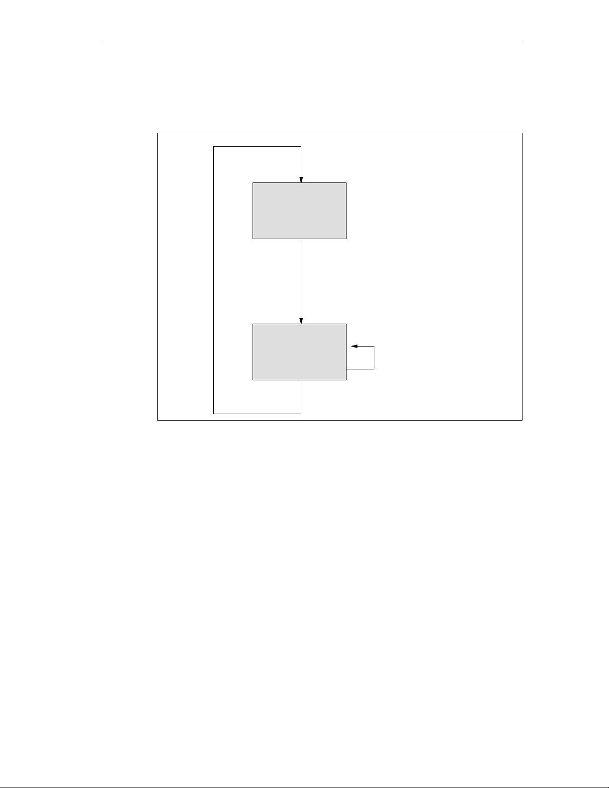
Send data
Basic Principles of Serial Data Transmission
The figure below illustrates a send operation.
Waiting for
send job
Send job arrived
Job processed
Sending user
Figure 2-4 Sequence of a Send Operation
Receiving Data with the ASCII Driver
In data transmission using the ASCII driver, you can choose between three
different end criteria when data is received. The end criterion defines when a
complete message frame is received. The possible end criteria are as follows:
• On Expiry of Character Delay Time
The message frame has neither a fixed length nor a defined end-of-text
character; the end of the message is defined by a pause on the line (expiry of
character delay time).
• On Receipt of One or More End-of-Text Character(s)
data
The amount of data to
be sent is taken from
the LEN parameter of
the send job.
The end of the message frame is marked by one or two defined end-of-text
characters.
• On Receipt of a Fixed Number of Characters
The length of the receive message frames is always identical.
Point-to-point connection CP 440 Installation and Parameter Assignment
A5E00057742-02
2-13
Page 32

Basic Principles of Serial Data Transmission
Code Transparency
The code transparency of the procedure depends on the selection of the
parameterized end criterion and the flow control:
• With one or two end-of-text characters
– Not code-transparent
• When the end criterion is the character delay time or a fixed message frame
length
– Code-transparent
• Code-transparent operation is not possible when XON/XOFF flow control is
used.
Code-transparent means that any character combination can occur in the user
data without the end criterion being detected.
2-14
Point-to-point connection CP 440 Installation and Parameter Assignment
A5E00057742-02
Page 33
Basic Principles of Serial Data Transmission
End Criterion: “Expiration of Character Delay Time”
When data is received, the end of the message frame is detected when the
character delay time expires. The received data is accepted from the CPU.
In this case, the character delay time must be set such that it reliably expires
between two consecutive message frames. However, it should be long enough so
that the end of the message frame is not falsely identified whenever the
communication partner takes a send pause within a message frame.
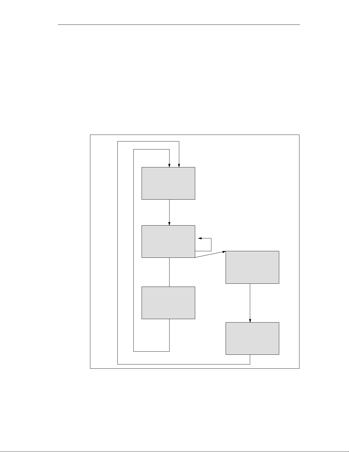
The figure below illustrates a receive operation with the end criterion “expiration of
character delay time”.
Waiting for
character
Character
arrived
Character received
with character
delay time
monitoring
Message frame buffered
Message frame
complete (character
delay time expired)
End criterion for message frame identified, error entry follows
Message frame
entered in receive
buffer
Error when receiving (not a
character delay time error)
Waiting for character
delay time. Received
characters discarded
Error entered in the
ST ATUS output of
the FB.
Figure 2-5 Sequence of Receive Operation with End Criterion “Expiration of Character
Delay Time”
Point-to-point connection CP 440 Installation and Parameter Assignment
A5E00057742-02
2-15
Page 34

Basic Principles of Serial Data Transmission
End Criterion: End-of-Text Character
When data is received, the end of the message frame is detected when the
parameterized end-of-text character(s) arrive. The following options are available:
• One end-of-text character
• Two end-of-text characters, 1st and 2nd end-of-text characters
• Two end-of-text characters, 1st or 2nd end-of-text character
The received data including the end-of-text character(s) is accepted from the CPU.
If the end-of-text character is missing in the received data, the character delay time
elapses during reception and results in a termination of the frame. The character
delay time is used in this instance as the monitoring time. An error message is
issued and the message frame fragment is discarded.
If you are working with end-of-text characters, transmission is not
code-transparent, and you must make sure that the end code(s) is/are not included
in the user data of the user.
Note the following when the last character in the received message frame is not
the end-of-text character.
• End-of-text character elsewhere in the message frame:
All characters including the end-of-text character are entered in the receive DB.
The characters following the end-of-text character:
– Are discarded if the monitoring time expires at the end of the message
frame.
– Are merged with the next message frame if a new message frame is
received before the monitoring time expires.
• End-of-text character not included in message frame:
The message frame:
– Is discarded if the monitoring time expires at the end of the message frame.
– Is merged with the next message frame if a new message frame is received
before the monitoring time expires.
2-16
Point-to-point connection CP 440 Installation and Parameter Assignment
A5E00057742-02
Page 35
Basic Principles of Serial Data Transmission
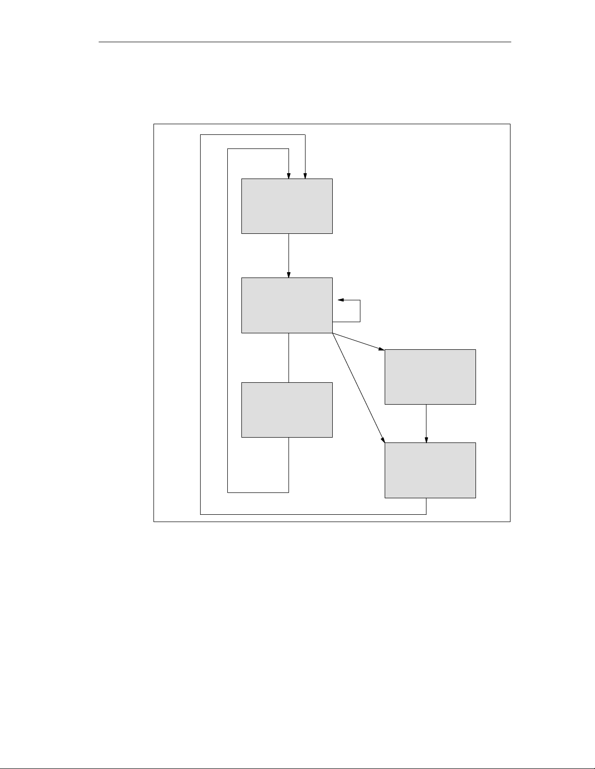
The figure below illustrates a receive operation with the end criterion “end-of-text
character”.
Waiting for
character
Character
arrived
Character received
with end control
and character delay
time
Message frame buffered
Message
frame
complete
End criterion for message frame identified, error entry follows
Figure 2-6 Sequence of Receive Operation with End Criterion “End-of-Text Character”
Message frame
entered in receive
buffer
Expiration
of the
monitoring
time
Error when receiving
Waiting for valid
end code
Error entered in the
ST ATUS output of
the FB.
Point-to-point connection CP 440 Installation and Parameter Assignment
A5E00057742-02
2-17
Page 36

Basic Principles of Serial Data Transmission
End Criterion: Fixed Frame Length
When data is received, the end of the message frame is detected when the
parameterized number of characters has arrived. The received data is accepted
from the CPU.
If the character delay time expires before the parameterized number of characters
has been reached, the receive operation is terminated. The character delay time is
used in this instance as the monitoring time. An error message is issued and the
message frame fragment is discarded.
Note the following if the message frame length of the received characters does
not match the parameterized fixed message frame length:
• Message frame length of received characters greater than parameterized fixed
message frame length:
All characters received after the parameterized fixed message frame length is
reached:
– Are discarded if the monitoring time expires at the end of the message
frame.
– Are merged with the next message frame if a new message frame is
received before the monitoring time expires.
• Message frame length of received characters less than parameterized fixed
message frame length:
The message frame:
– Is discarded if the monitoring time expires at the end of the message frame.
– Is merged with the next message frame if a new message frame is received
before the monitoring time expires.
2-18
Point-to-point connection CP 440 Installation and Parameter Assignment
A5E00057742-02
Page 37
Basic Principles of Serial Data Transmission
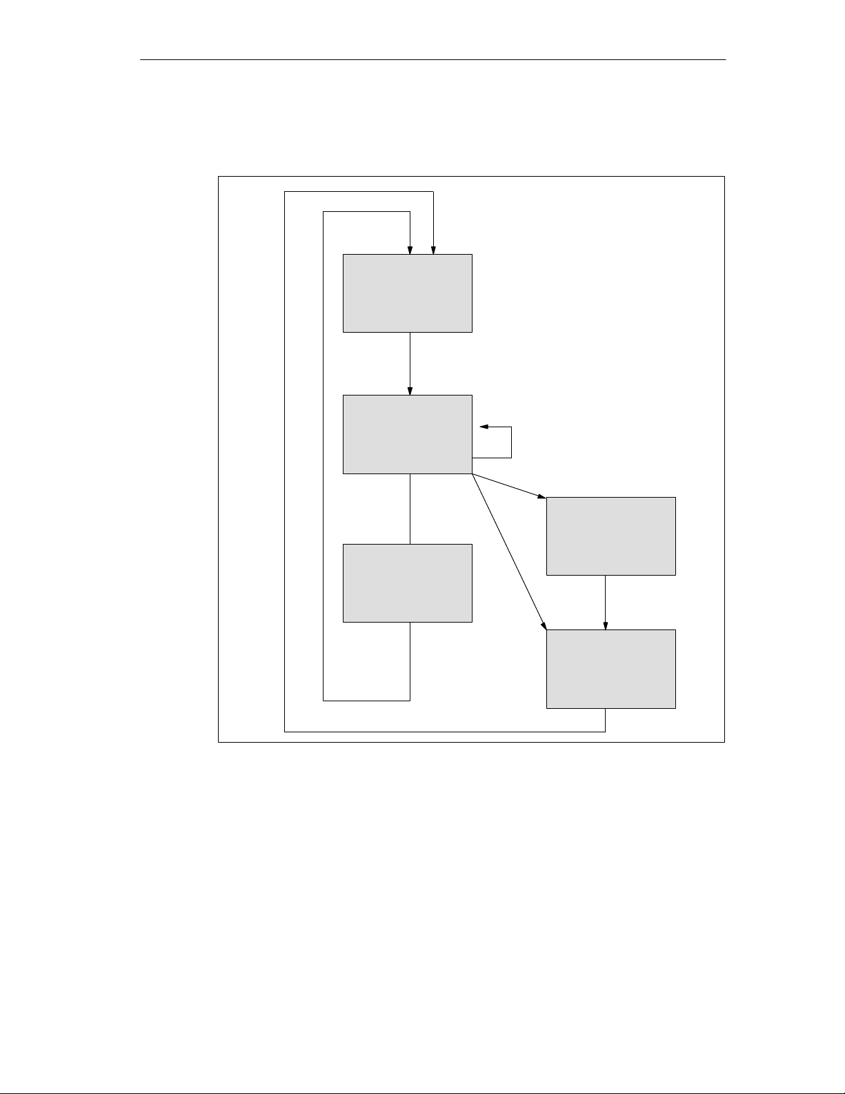
The figure below illustrates a receive operation with the end criterion “fixed
message frame length”.
Waiting for
character
Character
arrived
Character received
with length control
and character delay
time
Message
Message frame buffered
End criterion for message frame identified, error entry follows
frame
complete
Message frame
entered in receive
buffer
Error when receiving
Waiting for
parameterized
number of
characters
Expiration
of the
monitoring
time
Figure 2-7 Sequence of Receive Operation with End Criterion “Fixed Message Frame
Length”
Error entered in the
ST ATUS output of
the FB.
Point-to-point connection CP 440 Installation and Parameter Assignment
A5E00057742-02
2-19
Page 38

Basic Principles of Serial Data Transmission
Receive Buffer on the CP 440
The CP 440 receive buffer accommodates 2000 bytes. At parameterization you
can specify whether overwriting of data in the receive buffer should be prevented.
You can also specify the value range (1 to 10) for the number of buffered receive
message frames or use the entire receive buffer.
You can delete the CP receive buffer at startup. The setting can be made either by
using the parameterization interface or by calling the RES_RCV function block
(see Chapter 6).
The receive buffer on the CP 440 is a ring buffer:
• If two or more message frames are entered in the receive buffer of the CP 440,
the rule is that the oldest message frame is always transferred by the CP 440 to
the CPU.
• If you only ever want to send the most recent message frame to the CPU, you
must parameterize the value “1” for the number of buffered message frames
and deactivate the overwrite protection.
Note
If the constant reading out of the receive data in the user program is interrupted for
a while, you may find that when the receive data is requested again, the CPU first
receives old message frames from the CP 440 before it receives the most recent
one.
The old message frames are the ones that were on their way when transmission
between the CP 440 and the CPU was interrupted, or which had already been
received by the FB.
2-20
Point-to-point connection CP 440 Installation and Parameter Assignment
A5E00057742-02
Page 39

Data Flow Control/Handshaking
Handshaking controls the data flow between two communication partners.
Handshaking ensures that data is not lost in transmissions between devices that
work at different speeds. Software handshaking is supported with XON/XOFF in
the CP 440.
Data flow control is implemented as follows on the CP 440:
• As soon as the CP 440 is switched by parameterization to the flow control
operating mode, it sends the XON character.
• When the parameterized number of message frames is reached, or
alternatively 50 characters before the receive buffer overflows (size of the
receive buffer: 2000 bytes), the CP 440 sends the XOFF character. If the
communication partner continues to send data regardless of this, the receive
buffer overflows and an error message is generated. The data received in the
last message frame is discarded.
• As soon as a message frame is fetched by the S7 CPU and the receive buffer
is ready to receive, the CP 440 sends the XON character.
Basic Principles of Serial Data Transmission
• If the CP 440 receives the XOF character, the CP 440 interrupts transmission.
If an XON character is not received before a parameterized time has elapsed,
the transmission is aborted and an appropriate error message (0708H) is
generated at the STATUS output of the function blocks.
Point-to-point connection CP 440 Installation and Parameter Assignment
A5E00057742-02
2-21
Page 40
Basic Principles of Serial Data Transmission
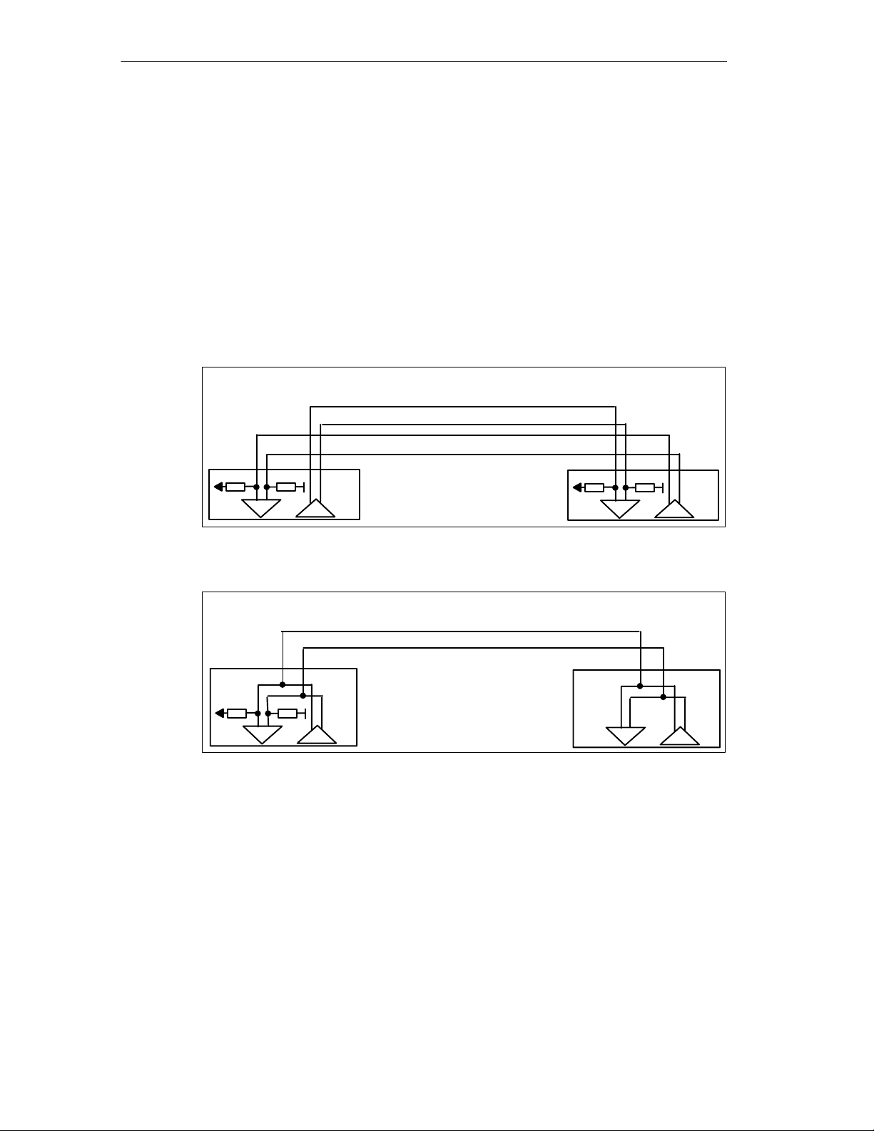
Topologies Between the Communication Partners
The CP 440 can be used in different topologies in the RS422 and RS485 operating
modes.
Distinctions are drawn between connections with:
– Two nodes (point-to-point) and
– Several nodes (multipoint)
In these cases the CP 440 can be used as:
– Master or
– Slave
Figure 2-8 RS 422 Point-to-Point
Figure 2-9 RS 485 Point-to-Point
In the case of a master/slave topology, there must be an appropriate message
frame in the user program. Example: The master sends all the slaves a message
frame with address information. All the slaves listen in and compare the address
with their own. If the address is the same, the addressed slave sends its answer.
The senders of all slaves must be able to switch to low impedance.
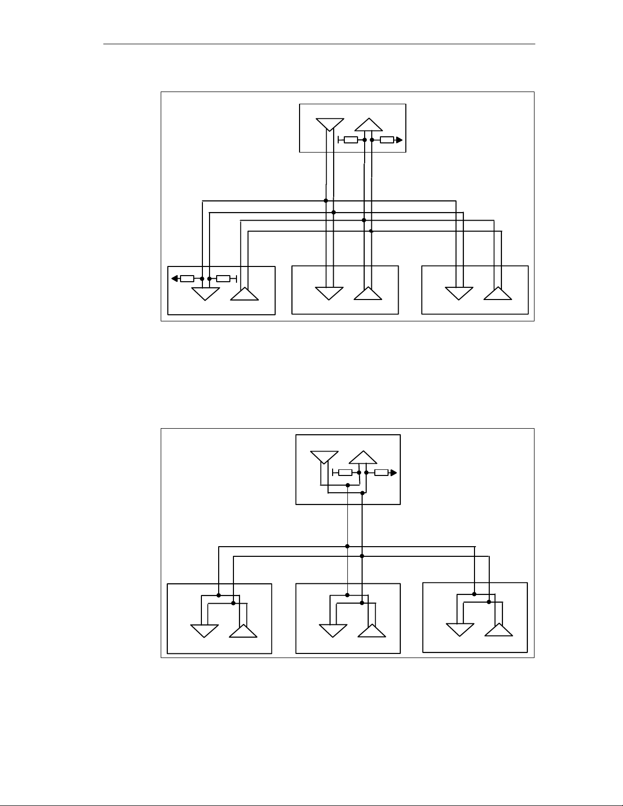
In the case of a master/slave topology in RS422 operation:
– The master ’s sender is interconnected with the receivers of all the slaves.
2-22
– The slaves’ senders are interconnected with the master’s receiver.
– Only the receiver of the master and the receiver of one slave have a default
setting. All the other slaves function without default settings.
Point-to-point connection CP 440 Installation and Parameter Assignment
A5E00057742-02
Page 41
Basic Principles of Serial Data Transmission
Master
Slave
Figure 2-10 RS 422 Multipoint
Slave
Slave
In the case of a topology in RS485 operation:
– The cable pair is interconnected for the send/receive line of all the nodes.
– Only the receiver of a node has a default setting. All the other modules
function without default settings.
Master
Slave
Figure 2-11 RS 485 Multipoint
Slave
The settings required for the different topologies can be made in the
parameterization interface in the “Interface” dialog box.
Point-to-point connection CP 440 Installation and Parameter Assignment
A5E00057742-02
Slave
2-23
Page 42

Basic Principles of Serial Data Transmission
Note
When you run the ASCII driver in RS422 multipoint or RS485 mode, you must
take steps in the user program to ensure that only one node sends data at any
one time. If two nodes send data simultaneously, the message frame is corrupted.
2.2.3 Data Transmission with the 3964(R) Procedure
The 3964(R) procedure controls data transmission via a point-to-point connection
between the CP 440 and a communication partner. In addition to the physical layer
(layer 1), the 3964(R) procedure also incorporates the data link layer (layer 2).
Control Characters
During data transmission, the 3964(R) procedure adds control characters to the
user data (data link layer). These control characters allow the communication
partner to check whether the data has arrived complete and without errors.
The 3964(R) procedure analyzes the following control codes:
• STX Start of Text; Start of character string for transfer
• DLE Data Link Escape; Data connection escape
• ETX End of Text; End of character string for transfer
• BCC Block Check Character (only with 3964(R)); Block check
character
• NAK Negative Acknowledge; Negative acknowledgment
Note
If DLE is transmitted as an information string, it is sent twice so that it can be
distinguished from the control code DLE during connection setup and cleardown
on the send line (DLE duplication). The receiver then reverses the DLE
duplication.
2-24
Point-to-point connection CP 440 Installation and Parameter Assignment
A5E00057742-02
Page 43

Priority
With the 3964(R) procedure, one communication partner must be assigned a
higher priority and the other partner a lower priority. If both partners begin
connection setup at the same time, the partner with the lower priority will defer its
send job.
Block Check Sum
With the 3964(R) transmission protocol, data integrity is increased by the additional
sending of a block check character (BCC).
Basic Principles of Serial Data Transmission
Message frame
STX Data DLE ETX BCC
02H 30H 31H 32H 10H 03H 20H
30 = 0011 0000
31 = 0011 0001
XOR = 0000 0001
32 = 0011 0010
XOR = 0011 0011
10 = 0001 0000
XOR = 0010 0011
03 = 0000 0011
XOR = 0010 0000
BCC 20
Figure 2-12 Block Checksum
The block checksum is the even longitudinal parity (EXOR logic operation of all
data bytes) of a sent or received block. Its calculation begins with the first byte of
user data (first byte of the message frame) after the connection setup, and ends
after the DLE ETX code on connection cleardown.
Note
If DLE duplication occurs, the DLE code is accounted for twice in the BCC
calculation.
Point-to-point connection CP 440 Installation and Parameter Assignment
A5E00057742-02
2-25
Page 44

Basic Principles of Serial Data Transmission
Sending Data with 3964(R)
The figure below illustrates the transmission sequence when data is sent with the
3964(R) procedure.
CP 440 Communication partner
Start code (02H)
Pos. acknowledgment (10H)
1st data byte
2nd data byte
nth data byte
End code (10H)
End code (03H)
3964(R) only
Pos. acknowledgment (10H)
Figure 2-13 Data Traffic when Sending with the 3964(R) Procedure
Establishing a Send Connection
To establish the connection, the 3964(R) procedure sends the control code STX. If
the communication partner responds with the DLE code before the
acknowledgment delay time (ADT) expires, the procedure switches to send mode.
If the communication partner answers with NAK or with any other control code
(except for DLE or STX), or the acknowledgment delay time expires without a
response, the procedure repeats the connection setup. After the parameterized
number of unsuccessful setup attempts, the procedure aborts the connection setup
and sends the NAK code to the communication partner. The CP 440 reports the
error to the SEND_440 function block (STATUS output parameter).
STX
DLE
1st byte
2nd byte
nth byte
DLE
ETX
BCC
DLE
Connection
setup
User
data
Connection
cleardown
2-26
Point-to-point connection CP 440 Installation and Parameter Assignment
A5E00057742-02
Page 45

Sending Data
If a connection is successfully established, the user data contained in the output
buffer of the CP 440 is sent to the communication partner with the selected
transmission parameters. The partner monitors the intervals between incoming
characters. The interval between two characters must not exceed the character
delay time.
If the communication partner sends the NAK control code during an active send
operation, the procedure aborts its transmission of the block and tries again as
described above, beginning with connection setup. If a different code is sent, the
procedure first waits for the character delay time to expire and then sends the NAK
code to change the mode of the communication partner to idle. Then the procedure
starts to send the data again with the connection setup STX.
Releasing a Send Connection
Once the contents of the buffer have been sent, the procedure adds the codes
DLE, ETX and in the case of 3964(R) only the block checksum BCC as the end
code, and waits for an acknowledgment code. If the communication partner sends
the DLE code within the acknowledgment delay time, the data block has been
received without errors. If the communication partner responds with NAK, any
other code (except DLE), or a damaged code, or if the acknowledgment delay time
expires without a response, the procedure starts to send the data again with the
connection setup STX.
Basic Principles of Serial Data Transmission
After the defined number of attempts to send the data block, the procedure stops
trying and sends an NAK to the communication partner. The CP 440 reports the
error to the SEND_440 function block (STATUS output parameter).
Point-to-point connection CP 440 Installation and Parameter Assignment
A5E00057742-02
2-27
Page 46

Basic Principles of Serial Data Transmission
Receiving Data with 3964(R)
The figure below illustrates the transmission sequence when data is received with
the 3964R procedure.
partner
CP 440Communication
Connection
setup
User
data
STX
DLE
1st byte
2nd byte
Pos. acknowledgment (10H)
Start code (02H)
1st data byte
2nd data byte
nth byte
DLE
Connection
cleardown
Figure 2-14 Data Traffic When Receiving with the 3964(R) Procedure
ETX
BCC
DLE
Pos. acknowledgment (10H)
Note
As soon as it is ready, the 3964(R) procedure sends a single NAK to the
communication partner to set the latter to idle.
nth data byte
End code (10H)
End code (03H)
3964(R) only
Establishing a Receive Connection
In idle mode, when there is no send job to be processed, the procedure waits for
the communication partner to establish the connection.
If no empty receive buffer is available during a connection setup with STX, a wait
time of 400 ms is started. If there is still no empty receive buffer after this time has
elapsed, the CP 440 reports the error (error message at the STATUS output of the
FB). The procedure sends an NAK and returns to idle mode. Otherwise, the
procedure sends a DLE and receives the data.
If the procedure receives any control code except for STX or NAK in idle mode, it
waits for the character delay time to expire, then sends the code NAK. The CP 440
reports the error to the RECV_440 function block (STATUS output parameter).
Point-to-point connection CP 440 Installation and Parameter Assignment
2-28
A5E00057742-02
Page 47

Receiving Data
After a successful connection setup, the receive characters that are arrive are
stored in the receive buffer. If two consecutive DLE codes are received, only one of
these is stored in the receive buffer.
After each receive character, the procedure waits out the character delay time for
the next character. If this period expires before another character is received, an
NAK is sent to the communication partner. The system program reports the error
to the RECV_440 function block (STATUS output parameter). The 3964(R)
procedure does not initiate a repetition.
If transmission errors occur during receiving (lost character, frame error, parity
error, etc.), the procedure continues to receive until the connection is cleared
down, then an NAK is sent to the communication partner. A repetition is then
expected. If the block still cannot be received after the number of transmission
attempts specified in the static parameter record, or if the communication partner
does not start the repetition within a block wait time of 4 seconds, the procedure
aborts the receive operation. The CP 440 reports the first failed transmission and
the final abortion of the receive operation to the RECV_440 function block
(STATUS output parameter).
Basic Principles of Serial Data Transmission
Cleardown of a Connection for Receiving
If the 3964 procedure detects the string DLE ETX, it stops receiving and sends to
the communication partner a DLE if the block was received without errors. If the
block is damaged it sends an NAK. A repetition is then expected.
If the 3964(R) procedure detects the string DLE ETX BCC, it stops receiving and
compares the received BCC with the internally calculated longitudinal parity. If the
BCC is correct and no other receive errors have occurred, the 3964(R) procedure
sends a DLE and returns to idle mode. If the BCC is errored or a different receive
error occurs, an NAK is sent to the communication partner. A repetition is then
expected.
Point-to-point connection CP 440 Installation and Parameter Assignment
A5E00057742-02
2-29
Page 48

Basic Principles of Serial Data Transmission
Handling Errored Data
The figure below illustrates how errored data is handled with the 3964(R)
procedure.
partner
CP 440Communication
Receiving data
Start code (02H)
Pos. acknowledgment (10H)
1st data byte
nth data byte
End code (10H)
End code (03H)
3964(R) only
Neg. acknowledgment (15H)
New setup attempt
Figure 2-15 Data Traffic When Receiving Errored Data
STX
DLE
1st byte
nth byte
DLE
ETX
BCC
NAK
T
Connection
setup
User
data
Connection
cleardown
When DLE, ETX and BCC are received, the CP 440 compares the BCC of the
communication partner with its own internally calculated value. If the BCC is
correct and no other receive errors occur, the CP 440 responds with DLE.
Otherwise, the CP 440 responds with NAK and waits the block wait time (T) of
4 seconds for a new attempt. If, after the parameterized number of transmission
attempts, the block cannot be received, or if no further attempt is made within the
block wait time, the CP 440 aborts the receive operation.
2-30
Point-to-point connection CP 440 Installation and Parameter Assignment
A5E00057742-02
Page 49

Initialization Conflict
The figure below illustrates the transmission sequence during an initialization
conflict.
Basic Principles of Serial Data Transmission
CP 440
(low priority)
Start code (02H)
Start code (02H)
Pos. acknowledgment (10H)
1st data byte
2nd data byte
nth data byte
End code (10H)
End code (03H)
3964(R) only
Pos. acknowledgment (10H)
2nd setup attempt
Start code (02H)
Pos. acknowledgment (10H)
STX
STX
DLE
1st byte
2nd byte
nth byte
DLE
ETX
BCC
DLE
STX
DLE
Communication partner
(higher priority)
Connection
setup
User
data
Connection
cleardown
Connection
setup
Figure 2-16 Data Traffic during an Initialization Conflict
If a device responds to the communication partner ’s send job (code STX) within
the acknowledgment delay time (ADT) by sending the code STX instead of the
acknowledgment DLE or NAK, an initialization conflict occurs. Both devices want to
execute a send job. The device with the lower priority withdraws its send job and
responds with the code DLE. The device with the higher priority sends its data in
the manner described above. Once the connection has been cleared down, the
lower-priority device can execute its send job.
To be able to resolve the initialization conflict, you must parameterize the
communication partners with different priorities.
Point-to-point connection CP 440 Installation and Parameter Assignment
A5E00057742-02
2-31
Page 50
Basic Principles of Serial Data Transmission
Procedure Errors
The procedure detects both errors which are caused by the communication partner
and errors caused by faults on the line.
In both cases, the procedure makes repeated attempts to send/receive the data
block correctly. If this is not possible within the maximum number of transmission
attempts set (or if a new error status occurs), the procedure aborts the send or
receive operation. It reports the error number of the first detected error and returns
to idle mode. These error messages are displayed in the STATUS output of the
FB.
If the system program regularly reports an error number at the STATUS output of
the FB for send and receive repetitions, this indicates occasional trouble affecting
the data traffic. The large number of transmission attempts compensates for this,
however. In this case you are advised to check the transmission connection for
possible sources of interference, because frequent repetitions reduce the
user-data rate and integrity of the transmission. The disturbance could also be
caused, however, by a malfunction on the part of the communication partner.
If BREAK occurs on the receive line (receive line interrupted), an error is displayed
at the STATUS output of the FB. No repeat is started. The BREAK status is
automatically reset as soon as the connection is restored on the line.
For every detected transmission error (lost character, frame or parity error), a
standard number is reported, regardless of whether the error was detected during
sending or receiving of a data block. The error is only reported, however, following
unsuccessful repetitions.
Startup of the 3964(R) Procedure
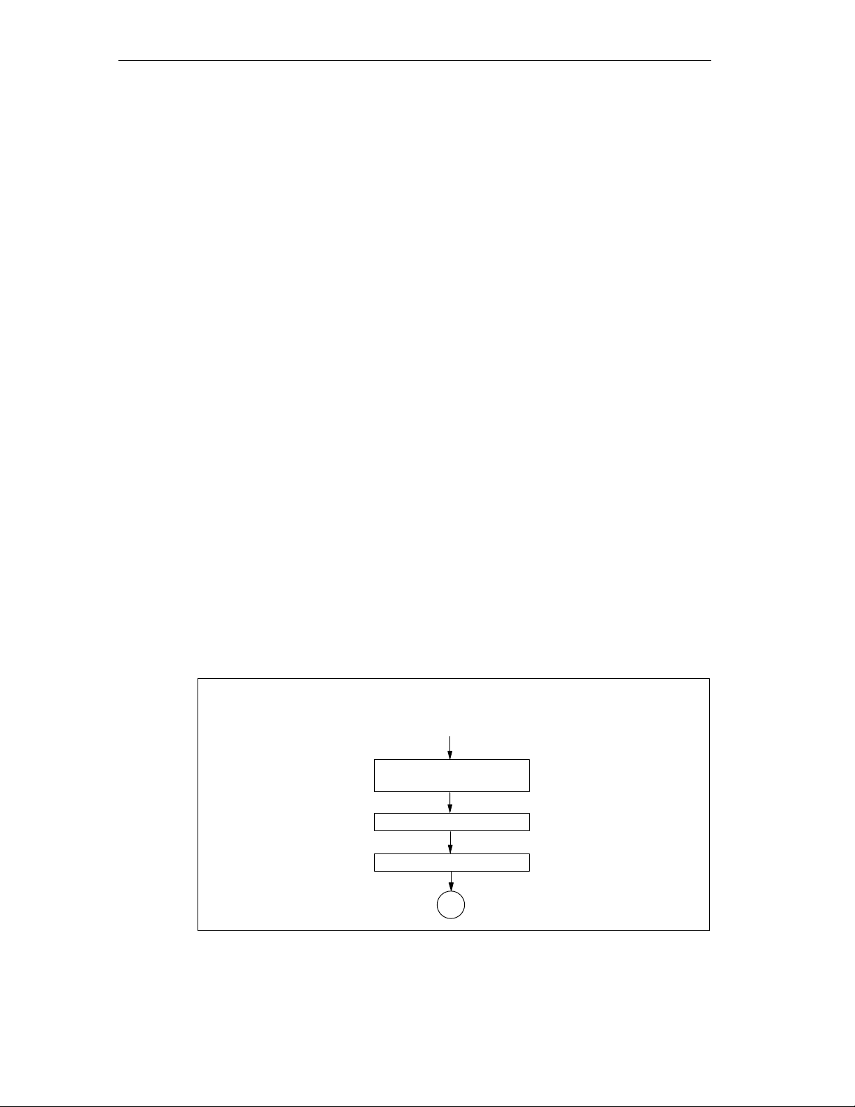
The figure below illustrates the startup of the 3964(R).
Power-up after restart of the CPU
or voltage recovery
Evaluate parameter
assignment
Initialize interface
2-32
Send NAK
G
Figure 2-17 Flow Diagram of the Startup of the 3964(R) Procedure
Point-to-point connection CP 440 Installation and Parameter Assignment
A5E00057742-02
Page 51
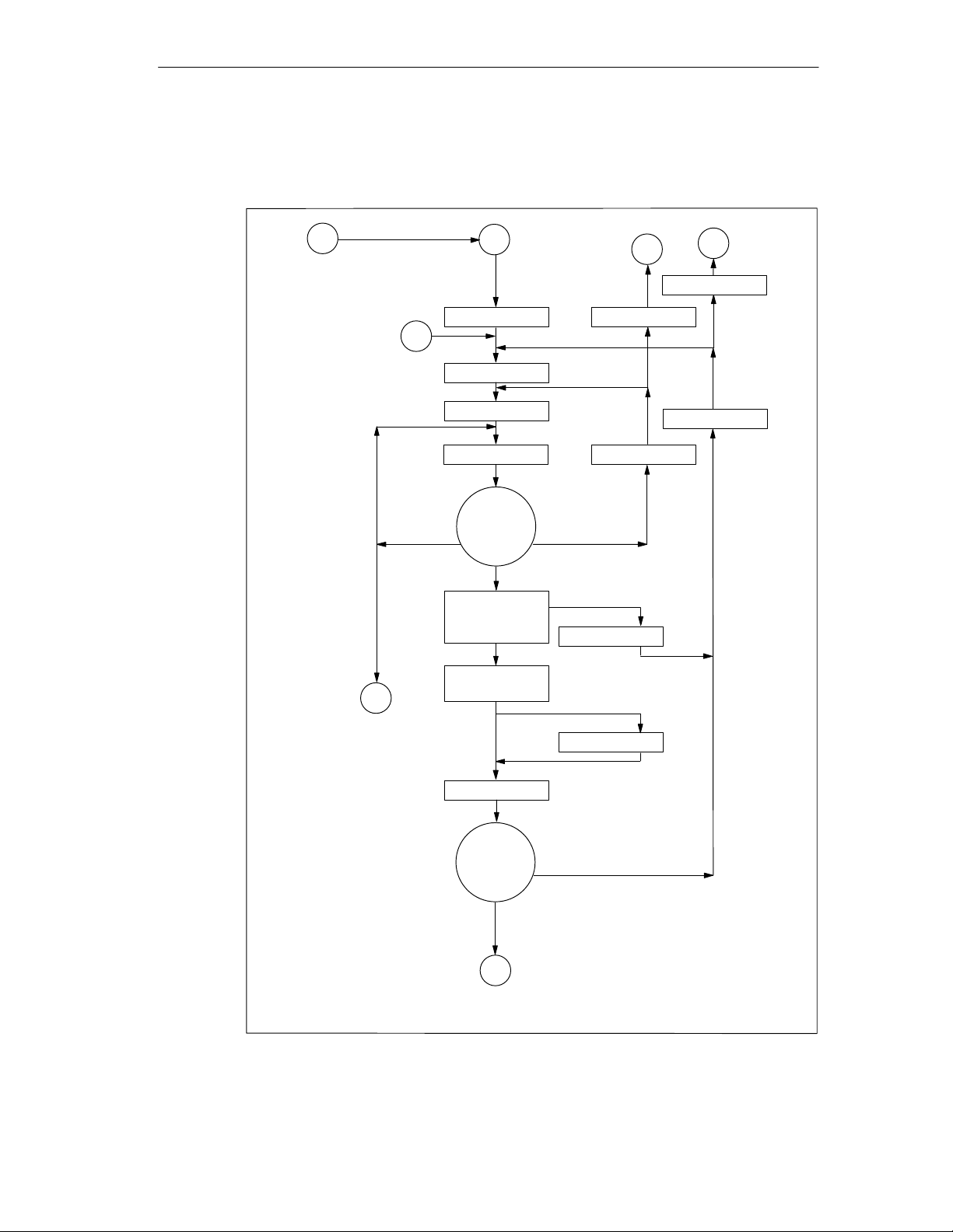
Sending with the 3964(R) Procedure
The figure below illustrates sending with the 3964(R) procedure.
Basic Principles of Serial Data Transmission
G
High
priority
Low
priority
Intention to
2
send
G
G
Send NAK
W = 1
3
x = 1
Send STX
Start T
ADT
T > T
ADT
Send NAK
x <= 6
,
x <= 6
x > 6
x > 6
W + 1
x + 1
character except
DLE, STX or
invalid characters
DLE
Receipt not
permitted
STX
Wait for DLE
acknowledg-
ment
Send block,
poss.
duplicate DLE
Send NAK
Send DLE,
1
ETX
3964(R)
3964
Start T
ADT
T > T
character except
Wait for DLE
acknowledg-
ment
DLE or invalid
character
DLE
BCC only with 3964(R)
x = setup attempt counter
T
=500 ms (3964(R) T
ADT
W = transmission attempt counter
Immediate return to initial state at line break (BREAK)
ADT
=2s)
Sending completed
G
Figure 2-18 Flow Diagram of Sending with the 3964(R) Procedure
Point-to-point connection CP 440 Installation and Parameter Assignment
A5E00057742-02
Send BCC
,
ADT
2-33
Page 52
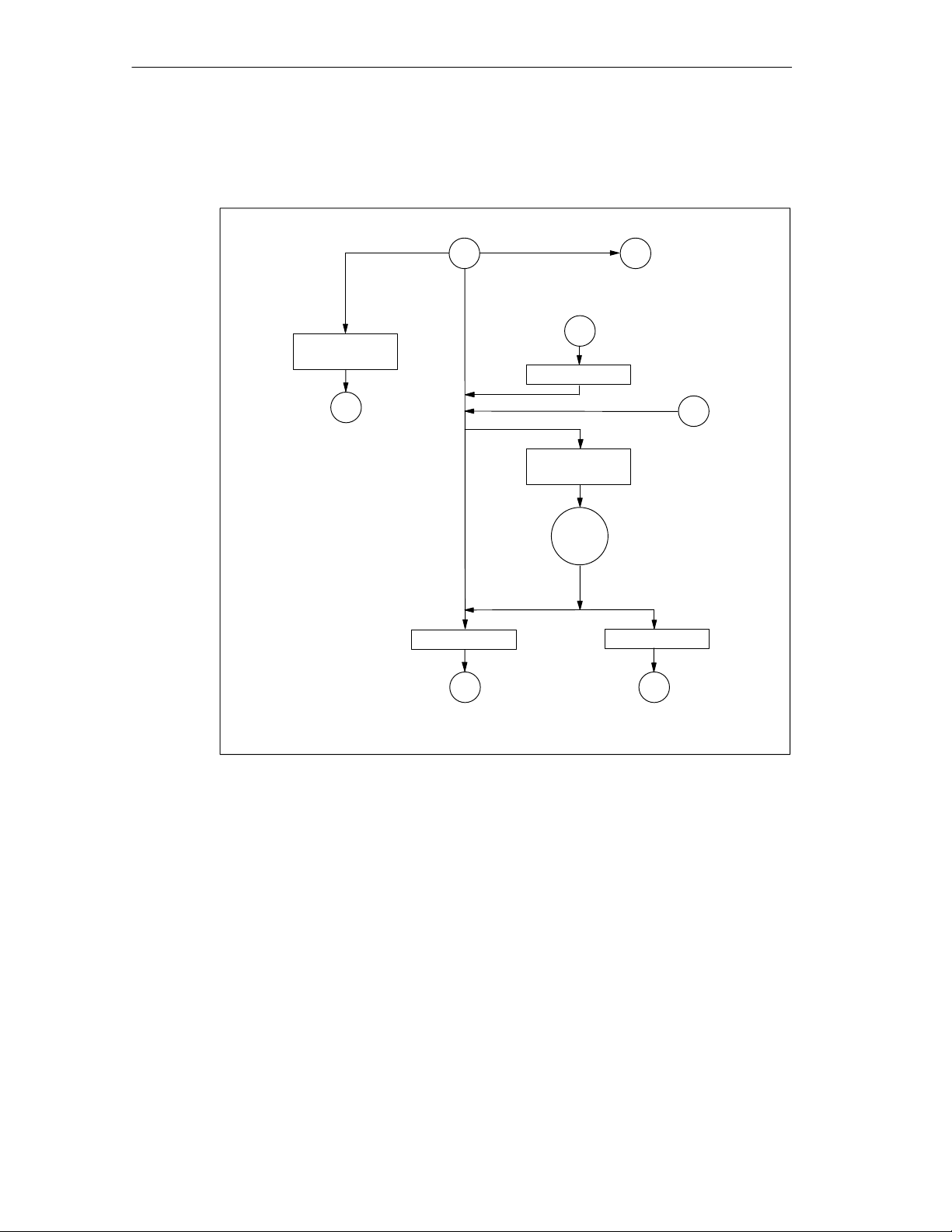
Basic Principles of Serial Data Transmission
Receiving with the 3964(R) Procedure (Part 1)
The figure below illustrates receiving with the 3964(R) procedure.
Characters except
STX, NAK
Note
NAK
4
G
Send DLE
Intention to send
2
Receive
STX
Repetition
expected
1
W +1
Start
T
NAKTIM
Wait
T > T
NAKTIM
Buffer free Buffer not free
Send NAK
5
Initialization
conflict, low
priority
4
T
= 400 ms
NAKTIM
W = transmission attempt counter
Immediate return to initial state at line break (BREAK)
G
Figure 2-19 Flow Diagram of Receiving with the 3964(R) Procedure (Part 1)
2-34
Point-to-point connection CP 440 Installation and Parameter Assignment
A5E00057742-02
Page 53
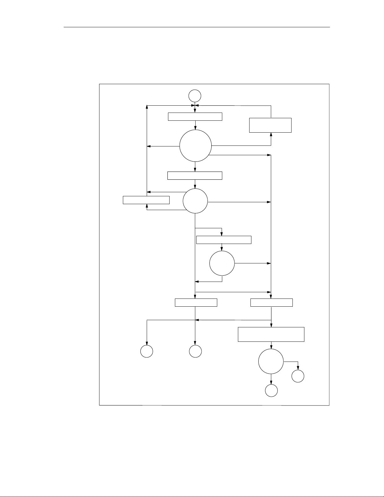
Basic Principles of Serial Data Transmission
Receiving with the 3964(R) Procedure (Part 2)
The figure below illustrates receiving with the 3964(R) procedure.
4
Start T
Start T
char. delay time
Wait to
receive
characters
DLE
char. delay time
Correct
character
except
for DLE
Dual DLE
Invalid character
T > T
char. delay time
Note
NAK
Note NAK
Characters
except ETX, DLE
Wait for
ETX
T > T
ETX
3964(R)
3964
Start T
Wait for
NAK noted
Initialization conflict
noted, low priority
3
Times: T
char. delay time
W = transmission attempt counter
BCC only with 3964(R)
Immediate return to initial state at line break (BREAK)
= 220 ms, T
Send DLE
G
= 4 s
Block
Receipt completed
char. delay time
char. delay time
T > T
BCC
delay time
BCC incorrect
BCC
expected, start T
char.
Send NAK
W > 5
W <= 5
Note repetition
Wait for
STX
STX
1
BLOCK
T >
T
BLOCK
G
Figure 2-20 Flow Diagram of Receiving with the 3964(R) Procedure (Part 2)
Point-to-point connection CP 440 Installation and Parameter Assignment
A5E00057742-02
2-35
Page 54

Basic Principles of Serial Data Transmission
Receive Buffer on the CP 440
The CP 440 receive buffer accommodates 2000 bytes. At parameterization you
can specify whether overwriting of data in the receive buffer should be prevented.
You can also specify the value range (1 to 10) for the number of buffered receive
message frames or use the complete receive buffer.
You can delete the CP receive buffer at startup. The setting can be made either by
using the parameterization interface or by calling the RES_RCV function block
(see Chapter 6).
The receive buffer on the CP 440 is a ring buffer:
• If two or more message frames are entered in the receive buffer of the CP 440,
the rule is that the oldest message frame is always transferred by the CP 440 to
the CPU.
• If you only ever want to send the most recent message frame to the CPU, you
must parameterize the value “1” for the number of buffered message frames
and deactivate the overwrite protection.
Note
If the constant reading out of the receive data in the user program is interrupted for
a while, you may find that when the receive data is requested again, the CPU first
receives old message frames from the CP 440 before it receives the most recent
one.
The old message frames are the ones that were on their way when transmission
between the CP 440 and the CPU was interrupted, or which had already been
received by the FB.
2-36
Point-to-point connection CP 440 Installation and Parameter Assignment
A5E00057742-02
Page 55

Commissioning the CP 440
In Section You Will Find on Page
3.1 Sequence of Steps to Be Taken 3-2
3.2 Commissioning the Physical Interface 3-4
3
Point-to-point connection CP 440 Installation and Parameter Assignment
A5E00057742-02
3-1
Page 56

Commissioning the CP 440
3.1 Sequence of Steps to Be Taken
Before starting up the CP 440 you will need to perform the following steps in the
specified sequence.
1. Install the CP 440
2. Configure the CP 440
3. Parameterize the CP 440
4. Save the parameterization data
5. Create a user program for the CP 440
Installing the CP 440
Installing the CP 440 involves inserting it into the mounting rack of your
programmable controller.
For a detailed description, see Chapter 4.
Connecting the CP 440 to the Communication Partner
The connection to your communication partner is made using the connecting cable
described in Appendix B. You can find additional information on setting up the
physical interface in Section 3.2.
Configuring the CP 440
Configuring the CP 440 involves entering it in the configuration table. The CP 440
is configured using the STEP 7 software.
For a detailed description, see Section 5.1.
Parameterizing the CP 440
Parameterizing the CP 440 involves creating the specific parameters of the
protocols. You parameterize the CP 440 with the
Communication, Parameter Assignment
For a detailed description, see Section 5.2.
parameterization interface.
CP 440: Point-to-Point
Saving the Parameterization Data
Saving the parameterization data of the CP 440 involves saving the parameters,
downloading them to the CPU and transferring them to the CP 440. You use the
STEP 7 software to store the parameterization data.
3-2
For a detailed description, see Section 5.4.
Point-to-point connection CP 440 Installation and Parameter Assignment
A5E00057742-02
Page 57

Creating a User Program for the CP 440
Programming the CP 440 involves configuring it for the associated CPU using the
STEP7 user program. The CP 440 is programmed using the language editors of
the STEP 7 software.
A detailed description of programming with STEP 7 is contained in the
Programming with STEP 7
Communication using the function blocks of the CP 440 is described in Chapter 6.
Chapter 9 contains a detailed programming example.
manual.
Commissioning the CP 440
Point-to-point connection CP 440 Installation and Parameter Assignment
A5E00057742-02
3-3
Page 58

Commissioning the CP 440
3.2 Commissioning the Physical Interface
If there is no communication with the partner device after configuration has been
completed, you should test the connection. To do this, proceed as follows:
1. What might be the possible cause:
– Is the polarity of the send/receive lines reversed?
– Are the default settings correct? Several defaults may have been set with
different polarity. The default settings may already be integrated in the
device on a permanent basis.
– Incorrect or missing terminating resistors?
– High byte and low byte mixed in the security word (e.g. CRC)?
2. How to proceed:
– First of all use the manual to check the line connection:
– Assignment (Appendix B)
– Polarity (Appendix B)
– Default settings (Section 5.3)
– Carry out a setup test
3. Carry out the simplest setup possible:
– Connect only 2 nodes to each another
– If possible, use 2-wire cable (RS485)
– Use a short connecting cable
– Terminating resistors are not required due to the short distance
– Send first in one direction and then in the other
4. Check:
Always monitor the TXD send and RXD receive LEDs during the following
operations:
Example 1: The polarity of the line is definitely correct
– The default settings (all options) vary
– Check the security word (e.g. CRC)
Example 2: The default settings are definitely correct
– Reverse the connections (note: cross both pairs of lines in the RS422)
– Check the security word (e.g. CRC)
3-4
Point-to-point connection CP 440 Installation and Parameter Assignment
A5E00057742-02
Page 59

Commissioning the CP 440
Example 3: Neither correct polarity nor correct default settings known
– Reverse the connections (note: cross both pairs of lines in the RS422)
– If not OK, change the default settings (all options) with an appropriate
communication attempt
– If not OK, change the connections back, and change the default settings (all
options)
– Check the security word (e.g. CRC)
When setting up again, don’t forget to put back the terminating resistors you
removed.
5. Additional tips:
– If possible, connect an interface tester (possibly the V.24 converter →
RS22/485) to the connecting cable.
– Check the signal level using a measuring device (measure level to GND
(pin 8)).
– Some devices do not signal reception if data is being received but the CRC
security word is not correct.
– If necessary, replace the module to exclude the possibility of an electrical
defect.
Point-to-point connection CP 440 Installation and Parameter Assignment
A5E00057742-02
3-5
Page 60

Commissioning the CP 440
3-6
Point-to-point connection CP 440 Installation and Parameter Assignment
A5E00057742-02
Page 61

Installing the CP 440
In Section You Will Find on Page
4.1 CP 440 Slots 4-2
4.2 Installing and Removing the CP 440 4-3
4.3 Installation Guidelines 4-4
4
Point-to-point connection CP 440 Installation and Parameter Assignment
A5E00057742-02
4-1
Page 62

Installing the CP 440
4.1 CP 440 Slots
On the rack of the S7-400 programmable controller there are no specific slots
reserved for communication modules.
Position of the CP 440 on the Rack
The CP 440 can be plugged into any slot on the rack, with the following exception:
On all racks the power supply module occupies slots 1 to 3, depending on its
width.
For further information on slots, see /2/
/2/
S7-400/M7-400 Programmable Controllers, Hardware and Installation
Point-to-point connection CP 440 Installation and Parameter Assignment
4-2
manual
A5E00057742-02
Page 63

4.2 Installing and Removing the CP 440
When installing and removing the CP 440, you must observe certain rules.
Tool
For installing and removing the CP 440 you require a 3.5 mm cylindrical
screwdriver.
Installation Sequence
To install the CP 440 on a rack, proceed as follows:
1. Remove the filler panel from the slot you want to use by gripping it where
marked and pulling it toward you.
2. Insert the CP 440 module and tilt it downward.
3. Screw the module down at the top and bottom with a torque of
0.8 ... 1.1 Nm.
Installing the CP 440
Removal Sequence
To remove the CP 440 from the rack, proceed as follows:
1. Undo the screws at the top and bottom of the module.
2. Tilt the module upward and remove it.
3. Replace the filler panel over the empty slot.
Note
The CP 440 can be hot-plugged and hot-pulled, in other words with voltage
applied. This means that the CP 440 can be replaced while the programmable
logic controller is in operation.
To avoid the CPU going into STOP, OB 83 (insert/remove interrupt) and OB 122
(I/O access error) must be programmed.
The CP 440 is parameterized automatically once it has been inserted. The CP 440
then resumes operation.
Point-to-point connection CP 440 Installation and Parameter Assignment
A5E00057742-02
4-3
Page 64

Installing the CP 440
4.3 Installation Guidelines
To be Observed
The general installation guidelines for the S7-400 must be observed (see the
S7-400/M7-400 Programmable Controllers, Hardware and Installation
To meet the EMC (electromagnetic compatibility) values, the cable shield must be
connected to a shield bus.
manual).
4-4
Point-to-point connection CP 440 Installation and Parameter Assignment
A5E00057742-02
Page 65

Configuring and Parameterizing the CP 440
In Section You Will Find on Page
5.1 Configuring the CP 440 5-2
5.2 Parameterizing the Communication Protocols 5-3
5.3 Parameterization Data 5-4
5.4 Management of the Parameter Data 5-20
5.5 Subsequent Loading of Firmware Updates 5-21
Configuration Options
You configure and parameterize the CP 440 using STEP 7 or the
Point-to-Point Communication, Parameter Assignment
Table 5-1 Configuration Options for the CP 440
Product
CP 440 6ES7 440-1CS00-0YE0 As of version 5.1 As of version 4.0.2
parameterization interface.
Order Number Parameterized
Using the
Parameterization
Interface
5
CP 440:
Under STEP 7
Point-to-point connection CP 440 Installation and Parameter Assignment
A5E00057742-02
5-1
Page 66

Configuring and Parameterizing the CP 440
5.1 Configuring the CP 440
After the CP 440 has been installed, you must make the CP 440 known to the
programmable logic controller. This process is known as “configuration”.
Requirements
The
CP 440 Point-to-Point Communication, Parameter Assignment
parameterization interface must be installed on the programming device/PC under
STEP 7 (see also Table 5-1).
Installation
The
CP 440: Point -to-Point Communication, Parameter Assignment
parameterization interface is supplied together with the function blocks and the
programming examples on a CD. Proceed as follows to install the
parameterization interface:
1. Insert the CD into the CD drive of your programming device/PC.
2. Under
double-clicking the “Add/Remove Programs” icon in “Control Panel”.
3. In the dialog box, select the CD drive and the Setup.exe file and start
installation.
4. Now follow the step-by-step instructions of the installation program.
Configuration
In the sense used here, configuration means entering the CP 440 in the
configuration table of the STEP 7 software. In the configuration table you enter the
rack, the slot and the order number of the CP 440. STEP 7 then automatically
assigns an address to the CP 440.
The CPU is now able to find the CP 440 in its slot in the rack by way of its address.
Requirements
Before you can enter the CP 440 in the configuration table of the STEP 7 software,
you must have created a project and a station using STEP 7.
Further Information
Configuration of S7-400 modules is described in detail in the
and Communication Connections STEP 7
Windows 95/NT
or
Windows 98
, start the dialog for installing software by
Configuring Hardware
manual
, V5.0
.
5-2
In addition, STEP 7’s online help system will provide you with all the assistance
you will need when configuring an S7-400 module.
Point-to-point connection CP 440 Installation and Parameter Assignment
A5E00057742-02
Page 67

Configuring and Parameterizing the CP 440
5.2 Parameterizing the Communication Protocols
Once you have entered the CP 440 in the configuration table, you have to assign
parameters to the CP 440 communication processors and the interface
submodules of the CP 440.
Parameterization
The term “parameterization” is used in the following to describe the setting of
protocol-specific parameters. You set these parameters using the
Point-to-Point Communication, Parameter Assignment
You start the parameterization interface by double-clicking the order number
(CP 440) in the configuration table or by selecting the CP 440 and choosing the
Edit Object Properties menu command. The “Properties - CP 440 ” dialog box
appears.
Click the “Parameters” button in order to select a protocol. Set the protocol and
double-click the icon for the transmission protocol (an envelope). This takes you to
the dialog box for setting the protocol-specific parameters.
parameterization interface.
CP 440:
Further Information
The
CP 440: Point-to-Point Communication, Parameter Assignment
parameterization interface is intuitive and easy to use; the procedure is the same
for all communication processors. For this reason, the parameterization interface is
not described in detail here.
The online help system provides all the assistance you will need when working with
the parameterization interface.
Note
To create a parameter record for the CP, you must select and save the protocol
settings at least once.
Point-to-point connection CP 440 Installation and Parameter Assignment
A5E00057742-02
5-3
Page 68

Configuring and Parameterizing the CP 440
5.3 Parameterization Data
You can set the response of the CP 440 to CPU STOP by means of the basic
parameters. By selecting different protocols, you can adjust your CP440
communication processor to suit the communication partner.
The sections that follow describe the basic parameters of the CP 440 and the
parameterization data for the ASCII driver and for the 3964(R) procedure.
5.3.1 Basic Parameters of the CP 440
Enter the basic parameters in the STEP 7 HW dialog box “Properties - CP 440 ”.
Open the dialog box by double-clicking the CP 440 in the configuration table of
STEP 7. Section 5.2 tells you how to enter the basic parameters of the CP 440.
The basic parameters are described in the table below.
Table 5-2 Basic Parameters of the CP 440
Parameter
Reaction to CPU Stop This parameter controls
Description Value Range Default Value
the storage of the
received frames in the
receive buffer.
You can find more
detailed information in
the following tables.
• Continue
• STOP
The transmission
process is terminated in
both cases. Frames are
received as described in
Tables 5-3 and 5-4.
• Continue
5-4
Point-to-point connection CP 440 Installation and Parameter Assignment
A5E00057742-02
Page 69

Configuring and Parameterizing the CP 440
How is the Storage of the Received Message Frames Controlled by Setting the
“Reaction to CPU Stop” Parameter?
The response depends on whether or not flow control is used.
Table 5-3 Control of Message Frame Storage Without Flow Control
Without Flow Control
Reaction to CPU Stop:
Continue
Reaction to CPU Stop:
STOP
Table 5-4 Control of Frame Storage with Flow Control
With Flow Control
Reaction to CPU Stop:
Continue
Reaction to CPU Stop:
STOP
Saved Frames Frame Just Arriving New Message Frames
Retained Saved; discarded if the
Retained Discarded Discarded
Saved Frames Frame Just Arriving New Frames
Retained Saved; flow control is
Retained Further data cannot be
buffer is full
activated if the buffer is
full.
received because flow
control is activated.
Saved until the buffer is
full, then discarded
Saved; flow control is
activated if the buffer is
full.
Further data cannot be
received because flow
control is activated.
Point-to-point connection CP 440 Installation and Parameter Assignment
A5E00057742-02
5-5
Page 70

Configuring and Parameterizing the CP 440
5.3.2 Parameterization Data of the ASCII Driver
Using the parameterization data of the ASCII driver, you can adjust the CP440 to
suit the communication partner.
Parameterization Data of the ASCII Driver
Using the
CP440: Point-to-Point Communication, Parameter Assignment
interface,
specify the parameters for the physical layer (layer 1) of the ASCII driver. Below
you will find a detailed description of the parameters.
Section 5.2 describes how to enter parameterization data using the
Point-to-Point Communication, Parameter Assignment
parameterization interface.
CP440:
Note
The ASCII driver can be used in four-wire mode (RS 422) and two-wire mode
(RS 485).
At parameterization, you must specify the type of interface (RS 422 or RS 485).
5-6
Point-to-point connection CP 440 Installation and Parameter Assignment
A5E00057742-02
Page 71

Protocol Parameters
The table below describes the protocol parameters.
Table 5-5 Protocol Parameters (ASCII Driver)
Configuring and Parameterizing the CP 440
Parameter
End ID of a
Receive
Message Frame
Character Delay
Time
Monitoring Time
for Missing
End ID
1st End ID
2nd End ID
Message Frame
Length
1
1
3
Description Value Range Default Value
Specifies the criterion that
indicates the end of each message
frame.
• On Expiry of Character
Delay Time
• On Receipt of Fixed
Number of Characters
• On Receipt of End
Character
The character delay time defines
the maximum permitted time
between 2 consecutively received
characters.
The character delay time is used
as the monitoring time for a
missing end code. This applies to
the following settings for the end
code
– On Receipt of Fixed
Number of Characters
– On Receipt of End
Character
First end code. • 7 data bits2:
1 to 65535 ms
The shortest character delay
time depends on the
transmission rate
bps
300
600
1200
2400
4800
9600
19200
38400
57600
76800
115200
0 to 7FH (hex)
• 8 data bits
0 to FFH (hex)
Second end code, if specified.
You can parameterize the following
for the end code:
– 1st end ID AND
2nd end ID
– 1st end ID OR 2nd end ID
When the end criterion is “fixed
message frame length”, the
number of bytes making up a
message frame is defined.
• 7 data bits
0 to 7FH (hex)
• 8 data bits
0 to FFH (hex)
1 to 200 (bytes) • 200
Character time
delay (ms)
130
65
32
16
8
4
2
1
1
1
1
2
:
2
:
2
:
• On Expiry of
Character
Delay Time
• 4 ms
• 3 (03H =
ETX)
• 0
Point-to-point connection CP 440 Installation and Parameter Assignment
A5E00057742-02
5-7
Page 72

Configuring and Parameterizing the CP 440
Table 5-5 Protocol Parameters (ASCII Driver)
Parameter Default ValueValue RangeDescription
Transmission
pause between
the messages
related to the
monitoring time
1
Can only be set if the end criterion is an end-of-text character.
2
Depends on whether you parameterize 7 or 8 data bits for the character frame (see Table 5-6).
3
Can only be set if the end criterion is a fixed message frame length.
A pause equal to the length of the
monitoring time (for a missing end
ID) is inserted between two
message frames when sending so
that the partner can synchronize
(detect receipt of the message
frame).
• Yes
• No
• Yes
5-8
Point-to-point connection CP 440 Installation and Parameter Assignment
A5E00057742-02
Page 73

Configuring and Parameterizing the CP 440
Transmission Rate/Character Frame
The table below describes the parameters for the transmission rate and character
frame.
Table 5-6 Transmission Rate/Character Frame (ASCII Driver)
Parameter
Transmission Rate Speed of data transmission in bps • 300
Description Value Range Default Value
• 600
• 1200
• 2400
• 4800
• 9600
• 19200
• 38400
• 57600
• 76800
• 115200
Start Bit During transmission, a start bit is prefixed to
each character to be sent.
Data Bits Number of bits to which a character is mapped. • 7
• 1 (fixed
value)
• 8
Stop Bits During transmission, a stop bit is appended to
every character to be sent to indicate the end of
the character.
Parity A sequence of information bits can be extended
to include another bit, the parity bit. The
addition of its value (0 or 1) brings the value of
all the bits up to a defined status. Thus the data
integrity is enhanced.
If “none” is specified for parity, no parity bit is
sent.
It is not possible to specify “none” if 7 data
bits are set.
• 1
• 2
• None
• Odd
• Even
• 9600
• 1
• 8
• 1
• Even
Point-to-point connection CP 440 Installation and Parameter Assignment
A5E00057742-02
5-9
Page 74

Configuring and Parameterizing the CP 440
Data Flow Control
In the following table the parameters for data flow control are described. Data flow
control is only possible when “Full Duplex (RS 422) Four-Wire Mode Point to Point”
is set.
Table 5-7 Data Flow Control (ASCII Driver)
Parameter
Data Flow Control Defines the type of data flow
control to be used.
XON Code
XOFF Code
Wait for XON after
XOFF (Wait Time
for CTS=ON)
1
2
3
1
1
3
Only in the case of XON/XOFF data flow control
Depends on whether you parameterize 7 or 8 data bits for the character frame (see Table 5-6).
Only in the case of XON/XOFF data flow control
Code for XON • 7 data bits2:
Code for XOFF • 7 data bits2:
Period of time for which the CP440
waits for the XON code or for
CTS=“ON” of the communication
partner when sending.
Description Value Range Default Value
• None
• None
• XON/XOFF
• 11 (DC1)
0 to 7FH (hex)
• 8 data bits
0 to FFH (hex)
2
:
• 13 (DC3)
0 to 7FH (hex)
• 8 data bits
0 to FFH (hex)
20 to 65535 ms
in 10 ms increments
2
:
• 20000 ms
Further Information
You will find more information on data flow control with XON/XOFF in
Section 2.2.2.
5-10
Point-to-point connection CP 440 Installation and Parameter Assignment
A5E00057742-02
Page 75

Receive Buffer on the CP
The table below describes the parameters for the CP receive buffer.
Table 5-8 Receive Buffer on the CP (ASCII Driver)
Configuring and Parameterizing the CP 440
Parameter
Delete CP Receive
Buffer on Startup
Buffered Receive
Message Frames
Prevent
Overwriting
During power up or during transition of
the CPU from STOP to RUN, the CP
receive buffer is deleted.
You can specify the number of receive
message frames to be buffered in the CP
receive buffer or that are to use the whole
buffer. If you use the whole buffer of
2000 bytes, the number of buffered
receive message frames depends only
on the length of the frames.
If you specify “1” here, disable the
“Prevent Overwriting” parameter and
cyclically read the received data from the
user program, a current message frame
will always be sent to the CPU.
You can use this parameter to prevent
data in the receive buffer being
overwritten when the buffer is full.
Further Information
You can find further information on handling the receive buffer under “Receive
Buffer on the CP 440” in Section 2.2.2.
Description Value Range Default Value
• Yes
• No
• No
• 1 to 10
• Use Whole Buffer
• Yes
• Use Whole
Buffer
• Yes
• No
Point-to-point connection CP 440 Installation and Parameter Assignment
A5E00057742-02
5-11
Page 76

Configuring and Parameterizing the CP 440
Operating Mode/Initial State of the Receive Line
The table below contains descriptions of the operating mode/initial state of the
receive line for the X27 (RS 422/485) interface.
Table 5-9 X27 (RS 422/485) Interface (ASCII Driver)
Parameter
Operating Mode Specifies whether the
X27 (RS 422/485) interface is to
be run in full-duplex mode
(RS 422) or half-duplex mode
(RS 485).
(See also Section 2.2.2).
Initial State of
the Receive
Line (see also
Figure 5-1)
None:
Signal R(A)5 Volt, Signal
R(B)0 Volt:
Signal R(A)0 Volt, Signal
R(B)5 Volt:
Description Value Range Default Value
This setting only makes sense
for bus-capable special
drivers.
Break evaluation is possible
with this initial state. Cannot
be set with “Full Duplex
(RS422) Four-Wire Mode
Multipoint Master” and “Half
Duplex (RS485) Two-Wire
Mode”)
This initial state corresponds
to the idle state (no sender
active). Break evaluation is not
possible with this initial state.
• Full Duplex (RS 422)
Four-Wire Mode Point to
Point
Operating mode for
point-to-point
communication in four-wire
mode
• Full Duplex (RS 422)
Four-Wire Mode Multipoint
Master
Operating mode for
multipoint communication
in four-wire mode if the CP
is a master
• Full Duplex (RS 422)
Four-Wire Mode Multipoint
Slave
Operating mode for
multipoint connection in
four-wire mode if the CP is
a slave
• Half Duplex (RS 485)
Two-Wire Mode
Operating mode for
point-to-point or multipoint
communication in two-wire
mode The CP can be a
master or slave.
• None
• Signal R(A)5 Volt Signal
R(B) 0 Volt (Break
Evaluation)
• Signal R(A)0 Volt
• SignalR(B)5 Volt
• Full Duplex
(RS 422)
Four-Wire
Mode Point
to Point
• Depends on
the operating
mode set
5-12
Point-to-point connection CP 440 Installation and Parameter Assignment
A5E00057742-02
Page 77
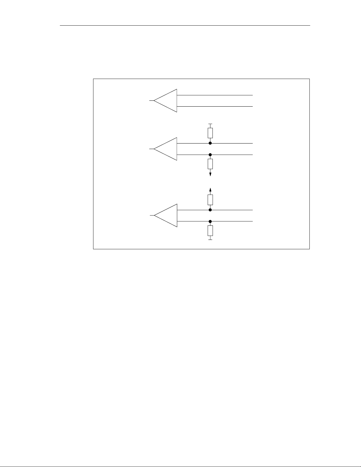
Initial State of the Receive Line
Figure 5-1 shows the wiring of the recipient at the X27 (RS 422/ 485) interface:
Configuring and Parameterizing the CP 440
none
0 V
R(A)5V/R(B)0V
5 V
5 V
R(A)0V/R(B)5V
0 V
Figure 5-1 Wiring of the Recipient at the X27 (RS 422/485) Interface (ASCII Driver)
R(B) +
R(A) –
R(B) +
R(A) –
R(B) +
R(A) –
Point-to-point connection CP 440 Installation and Parameter Assignment
A5E00057742-02
5-13
Page 78

Configuring and Parameterizing the CP 440
5.3.3 Parameterization Data of the 3964(R) Procedure
Using the parameterization data of the 3964(R) procedure, you can adjust the
CP440 to suit the communication partner.
Parameterization Data of the 3964(R) Procedure
Using the
CP 440 Point-to-Point Communication, Parameter Assignment
parameterization interface you set the parameters for the physical layer (layer 1)
and the data link layer (layer 2) of the 3964(R) procedure Below you will find a
detailed description of the parameters.
Section 5.2 describes how to enter the parameterization data using the
Point-to-Point Communication, Parameter Assignment
parameterization interface.
CP440:
Note
The 3964(R) procedure can only be used in four-wire mode.
5-14
Point-to-point connection CP 440 Installation and Parameter Assignment
A5E00057742-02
Page 79

Protocol
Ack. del
The following table describes the 3964(R) protocol.
Table 5-10 3964(R) Protocol
Configuring and Parameterizing the CP 440
Parameter
3964 Default Values
Without Block Check
3964(R) No Default Values
With Block Check
3964 No Default Values
Without Block Check
3964(R) No Default Values
With Block Check
Description Default Value
• The protocol parameters are set to default values.
• If the CP440 detects the string DLE ETX, it stops
receiving and sends DLE to the communication
partner if the block was received without errors, or
NAK if there were errors.
• The protocol parameters are set to default values.
• If the CP440 detects the string DLE ETX BCC, it
stops receiving and compares the received block
check character (BCC) with the longitudinal parity
calculated internally. If the BCC is correct and no
other receive errors have occurred, the CP440
sends the DLE code to the communication partner
(in the event of an error, the NAK code is sent).
• The protocol parameters are programmable.
• If the CP440 detects the string DLE ETX, it stops
receiving and sends DLE to the communication
partner if the block was received without errors, or
NAK if there were errors.
• The protocol parameters are programmable.
• If the CP440 detects the string DLE ETX BCC, it
stops receiving and compares the received block
check character (BCC) with the longitudinal parity
calculated internally. If the BCC is correct and no
other receive errors have occurred, the CP440
sends the DLE code to the communication partner
(in the event of an error, the NAK code is sent).
3964(R) Default
Values With
Block Check:
Char. delay time
= 220 ms
ay time
= 2000 ms
Setup
attempts = 6
Transmission
attempts = 6
Point-to-point connection CP 440 Installation and Parameter Assignment
A5E00057742-02
5-15
Page 80

Configuring and Parameterizing the CP 440
Protocol Parameters
You can only set the protocol parameters if you have not set the default values in
the protocol.
Table 5-11 Protocol Parameters (3964(R) Procedure)
Parameter
Character Delay
Time
Acknowledgment
Delay Time
Setup Attempts This parameter specifies the
Transmission
Attempts
The character delay time defines the
maximum amount of time permitted
between two incoming characters
within a message frame.
The acknowledgment delay time
defines the maximum amount of time
permitted for the partner’s
acknowledgment to arrive during
connection setup (time between STX
and partner’s DLE acknowledgment)
or cleardown (time between DLE ETX
and partner’s DLE acknowledgment).
maximum number of attempts the
CP440 is allowed in order to establish
a connection.
This parameter specifies the
maximum number of attempts
permitted to transfer a message frame
(including the first one) in the event of
an error.
Description Value Range Default Value
20 ms to 65535 ms in
10 ms increments
The shortest character
delay time depends on the
transmission rate
300 bps 60 ms
600 bps 40 ms
1200 bps 30 ms
2400 to
115200 bps 20 ms
20 ms to 65535 ms in
10 ms increments
The shortest
acknowledgment delay
time (ADT) depends on
the transmission rate:
300 bps 60 ms
600 bps 40 ms
1200 bps 30 ms
2400 to
115200 bps 20 ms
1 to 255 6
1 to 255 6
220 ms
2000 ms
(550 ms with
3964 and no
block check)
5-16
Point-to-point connection CP 440 Installation and Parameter Assignment
A5E00057742-02
Page 81

Configuring and Parameterizing the CP 440
Transmission Rate/Character Frame
The following table describes the transmission rate/character frame.
Table 5-12 Transmission Rate/Character Frame (3964(R) Procedure)
Parameter
Transmission Rate Speed of data transmission in bps • 300
Description Value Range Default Value
• 600
• 1200
• 2400
• 4800
• 9600
• 19200
• 38400
• 57600
• 76800
• 115200
Start Bit During transmission, a start bit is prefixed to
each character to be sent.
Data Bits Number of bits to which a character is mapped. • 7
• 1 (fixed
value)
• 8
Stop Bits During transmission, a stop bit is appended to
every character to be sent to indicate the end of
the character.
Parity A sequence of information bits can be extended
to include another bit, the parity bit. The
addition of its value (0 or 1) brings the value of
all the bits up to a defined status. The data
integrity is thus enhanced.
If “none” is specified for parity, no parity bit is
sent.
It is not possible to specify “none” if 7 data
bits are set.
Priority A partner has high priority if its send job takes
precedence over the send job of the other
partner. A partner has low priority if its send job
must wait until the send job of the other partner
has been dealt with. With the 3964(R)
procedure, you must parameterize both
communication partners with different priorities,
i.e. one partner is assigned high priority, the
other low.
• 1
• 2
• None
• Odd
• Even
• High
• Low
• 9600
• 1
• 8
• 1
• Even
• Low
Point-to-point connection CP 440 Installation and Parameter Assignment
A5E00057742-02
5-17
Page 82

Configuring and Parameterizing the CP 440
Receive Buffer on the CP
The table below describes the parameters for the CP receive buffer.
Table 5-13 Receive Buffer on the CP (3964(R) procedure)
Parameter
Delete CP Receive
Buffer on Startup
Buffered Receive
Message Frames
Prevent
Overwriting
During power up or during transition of
the CPU from STOP to RUN the CP
receive buffer is deleted.
You can specify the number of receive
message frames to be buffered in the CP
receive buffer or to use the whole buffer.
If you use the whole buffer of 2000 bytes,
the number of buffered receive message
frames depends only on the length of the
frames.
If you specify “1” here, disable the
“Prevent Overwriting” parameter and
cyclically read the received data from the
user program, a current message frame
will always be sent to the CPU.
You can use this parameter to prevent
data in the receive buffer being
overwritten when the buffer is full.
Further Information
You can find further information on handling the receive buffer under “Receive
Buffer on the CP 440” in Section 2.2.2.
Description Value Range Default Value
• Yes
• No
• No
• 1 to 10
• Use Whole Buffer
• Yes
• Use Whole
Buffer
• Yes
• No
5-18
Point-to-point connection CP 440 Installation and Parameter Assignment
A5E00057742-02
Page 83
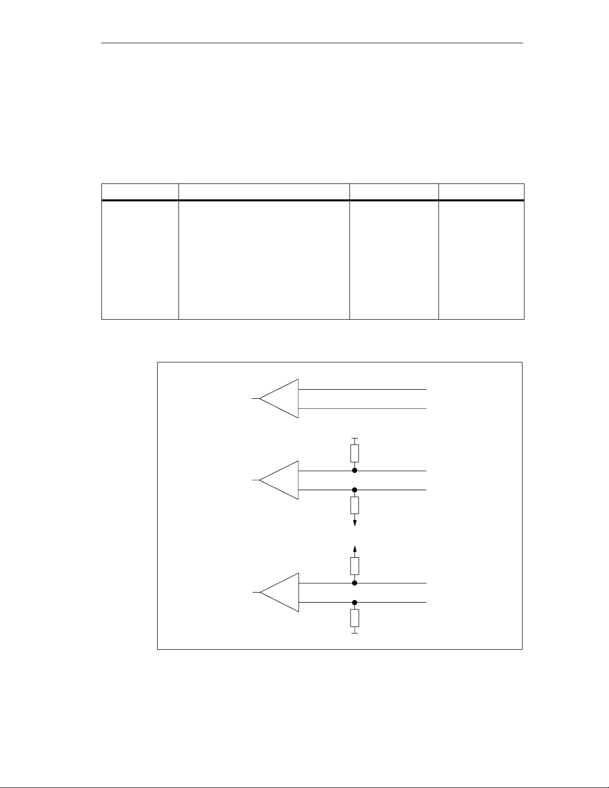
Initial State of the Receive Line
The table below contains a description of the initial state of the receive line for the
X27 (RS 422) interface. RS 485 operation is not possible in conjunction with the
3964(R) procedure.
Table 5-14 X27 (RS 422) Interface (3964(R) Procedure)
Configuring and Parameterizing the CP 440
Parameter
Initial State of the
Receive Line
The figure below shows the wiring of the recipient at the X27 (RS 422) interface:
Description Value Range Default Value
None: This setting only makes sense
with bus-capable drivers.
R(A)5V/R(B)0V: Break evaluation is
possible with this initial state.
R(A)0V/R(B)5V: Break evaluation is not
possible with this initial state.
(See also Figure 5-2.)
none
R(A)5V/R(B)0V
None R(A)5V/R(B)0V
Signal R(A)5
Volt (Break
Evaluation)
SignalR(B)0 Volt
SignalR(A)0 Volt
Signal R(B)5
Volt
R(B) +
R(A) –
0 V
R(B) +
R(A) –
R(A)0V/R(B)5V
Figure 5-2 Wiring of the Recipient at the X27 (RS 422) Interface (3964(R) Procedure)
Point-to-point connection CP 440 Installation and Parameter Assignment
A5E00057742-02
5 V
5 V
R(B) +
R(A) –
0 V
5-19
Page 84

Configuring and Parameterizing the CP 440
5.4 Management of the Parameter Data
The configuration and parameterization data of the CP 440 is saved in the current
project (on the hard disk of the programming device/PC).
Data Storage
When you exit the configuration table (see Section 5.1) by choosing the Station >
Save or Station > Save As menu command, the configuration and
parameterization data (including the module parameters) is automatically saved in
the project/user file you have created.
Downloading the Configuration and Parameters to the CPU.
You can download the configuration and parameterization data to the CPU from
the programming device (by choosing PLC > Download). The CPU puts the
parameters into effect as soon as they are loaded.
The module parameters are automatically transferred to the CP 440 in the
following cases:
• When they are downloaded to the CPU and the CP 440 can be reached via the
S7-400 backplane bus
• After power up during startup of the CPU, as soon as the CP 440 can be
reached via the S7-400 backplane bus
Unchanged parameters have the default value (see Section 5.3).
Further Information
You can find out how to do the following in the
Communication Connections STEP 7
• Save the configuration and parameters.
• Download the configuration and parameters to the CPU.
• Read, modify, copy and print the configuration and parameters.
Configuring Hardware and
manual:
5-20
Point-to-point connection CP 440 Installation and Parameter Assignment
A5E00057742-02
Page 85

5.5 Uploading Firmware Updates
Firmware updates can be uploaded to the operating-system memory of the CP 440
as patches.
Configuring and Parameterizing the CP 440
Firmware updates are loaded using the
Parameter Assignment
Basic Firmware
The CP 440 is shipped with basic firmware preinstalled.
Requirements
The prerequisites for loading firmware updates are:
• To update the firmware of the CP using the parameterization interface, you first
have to create a valid project under HWCONFIG and download it to the CPU.
• The instructions accompanying the firmware update always indicate the
destination directories for the files.
The ..\CP440.nnn path always identifies the firmware version.
CP 440: Point-to-Point Communication,
parameterization interface.
Point-to-point connection CP 440 Installation and Parameter Assignment
A5E00057742-02
5-21
Page 86

Configuring and Parameterizing the CP 440
Downloading Firmware
You download the firmware update to the CP 440 with the aid of the
Point-to-Point Communication, Parameter Assignment
parameterization interface.
CP 440:
Proceed as follows:
1. Switch the CPU to STOP mode.
2. Start the parameterization interface (see also Section 5.2):
In SIMATIC Manager: File > Open Object > Project > Open Hardware Config
> double-click CP 440 > choose the “Parameter” button.
3. Choose the Options > Firmware Update menu command.
Result:
If a connection can be established to the CP 440, the current module firmware
status is displayed.
If there is no firmware loaded on the CP 440, “ – – – – “ appears. This can
occur, for example, if a firmware update is canceled. The old firmware is
deleted in this case. You have to upload firmware to the module before it can be
restarted.
4. 3. Click the “Find File ...” button to select the firmware to be loaded
(header.upd).
Result:
The version of the firmware you select is displayed under “Status of selected
firmware:”.
5. Click the “Load Firmware” button to start uploading to the CP 440. You are
prompted for confirmation. The upload procedure is canceled immediately if you
click the “Cancel” button.
Note:
Before the basic firmware is deleted from the module, the CP 440 checks the
MLFB No. of the firmware to be downloaded in order to ensure that the
firmware is suitable for the CP 440.
Result:
The new firmware is loaded into the operating-system memory of the CP 440.
Under “Done” you can follow the progress of the operation in the form of a bar
chart and as a percentage. The module is immediately ready for operation
following the firmware update.
Power Failure During Firmware Uploading
If there is a failure when the firmware is being uploaded, the process must be
repeated. The module then has the state “CP 440 without module firmware” (see
Table 5-15).
5-22
Point-to-point connection CP 440 Installation and Parameter Assignment
A5E00057742-02
Page 87

LEDs
LED indicators for firmware update:
Table 5-15 LED Indicators for Firmware Update
Configuring and Parameterizing the CP 440
Status
Firmware update in
progress
Firmware update
completed
CP 440 without module
firmware
Hardware fault during
firmware update
INTF/EX
TF
on on on on – –
on off off off – –
flashing
(2Hz)
Flashing
(2Hz)
FAULT
on off off Module
Off Flashing
TXD RXD Comment Remedy
firmware
deleted,
firmware
update
canceled,
firmware
update still
possible
(2Hz)
Flashing
(2Hz)
Delete/write
failed
Reload the
firmware
Switch power
supply to
module off and
then on again
and reload the
firmware.
Check module
for defects.
Displaying the Hardware and Firmware Release
You can view the current version of the CP 440 hardware and firmware in
in the “Module Status” dialog box. To access this dialog box:
In SIMATIC Manager: File > Open Object > Project > Open HW Config >
Station > Open Online > and double-click the CP 440 module.
Point-to-point connection CP 440 Installation and Parameter Assignment
A5E00057742-02
STEP 7
5-23
Page 88

Configuring and Parameterizing the CP 440
5-24
Point-to-point connection CP 440 Installation and Parameter Assignment
A5E00057742-02
Page 89

Communication Using Function Blocks
In Section You Will Find on Page
6.1 Communication Using Function Blocks 6-2
6.2 Overview of the Function Blocks 6-3
6.4 Using the Function Blocks 6-5
6.5 Programming the Function Blocks 6-18
6.6 General Information on Program Processing 6-23
6.7 Technical Specifications of the Function Blocks 6-24
6
Point-to-point connection CP 440 Installation and Parameter Assignment
A5E00057742-02
6-1
Page 90

Communication Using Function Blocks
6.1 Communication Using Function Blocks
Communication between the CPU, the CP 440 and a communication partner takes
place via the function blocks and the protocols of the CP 440.
Communication Between the CPU and CP 440
The function blocks form the software interface between the CPU and the CP 440.
They must be called cyclically from the user program.
Restriction in Multicomputing Operation
In multicomputing operation only one CPU can access the CP because
communication between the CPU and CP is not multicomputing-compatible.
Communication Between the CP 440 and the Communication Partner
The transmission protocols are implemented on the CP 440. By means of the
protocol, the interface of the CP 440 is adapted to the interface of the
communication partner.
This enables you to link an S7 programmable logic controller with any
communication partner that can handle the ASCII driver and the 3964(R)
procedure.
Calling the Function Blocks in Interrupt OBs
It is not permissible to simultaneously call a function block in OB1 and in the
interrupt OB (time OBs). The reason for this is that the function block cannot be
called again if an interrupt OB triggers an interruption. If you need to call the
function block in OB1 and in the interrupt OB, you must disable the interrupts
(SFC 41) in the lower priority OB before the FB call and enable them again after
the FBs have executed.
6-2
Point-to-point connection CP 440 Installation and Parameter Assignment
A5E00057742-02
Page 91

6.2 Overview of the Function Blocks
The S7-400 programmable logic controller provides you with a number of function
blocks that initiate and control communication between the CPU and the CP 440
communication processor in the user program.
Function Blocks
The table below contains the function blocks of the CP 440 and describes their
purpose.
Table 6-1 Function Blocks of the CP 440
Communication Using Function Blocks
FB/FC
FB 9 “RECV_440” The RECV_440 function block allows you to receive data
from a communication partner and store it in a data block.
FB 10 “SEND_440” The SEND_440 function block allows you to send all or part
of a data block to a communication partner.
FB 11 “RES_RECV” The RES_RECV function block enables you to reset the
receive buffer of the CP 440.
Meaning Protocol
Form of Delivery and Installation
The function blocks of the CP 440 are on CD along with the parameterization
interface, the programming examples and the manual.
The function blocks are installed together with the parameterization interface.
Installation is described in Section 5.2. After installation, the function blocks are
stored in the CP 440 library.
You can open the library in STEP 7 SIMATIC Manager by choosing File > Open >
Library under CP PTP\CP 440\Blocks.
To work with the function blocks, you only need to copy the required function block
to your project.
ASCII driver, 3964
(R) procedure
ASCII driver, 3964
(R) procedure
ASCII driver, 3964
(R) procedure
Point-to-point connection CP 440 Installation and Parameter Assignment
A5E00057742-02
6-3
Page 92

Communication Using Function Blocks
6.3 Notes on Program Structure
In order to use the speed of the CP 440 to optimum effect, you should heed the
following when you create your user program:
In a short cycle (see also “CP 440 1CYC Programming Example” in Chapter 9):
• Only one run of the SEND_440 function block with REQ=0 and one run with
REQ=1 is necessary for data transmission (creating the positive edge at the
REQ input). The calls can be made directly one after the other. This makes it
possible to carry out one data transmission per cycle.
• Program the call of the SEND_440 FB with REQ=1 (this activates the FB) at
the end of the program. This ensures optimum use of the time between two
cycles, which can be relatively long in a short cycle.
In a long cycle:
• Call the SEND_440 and RECV_440 FBs several times throughout the program.
• Call the SEND_440 and RECV_440 FBs in the time OB (disable the interrupts
in the lower priority OBs).
Note when using interrupts (time OBs) that calling the corresponding OB requires
quite a lot of time (you can find exact times in your CPU manual). You should
therefore check in each case whether the FBs could be processed more effectively
by modifying your program.
6-4
Point-to-point connection CP 440 Installation and Parameter Assignment
A5E00057742-02
Page 93

6.4 Using the Function Blocks
The following sections describe what you must take into account when supplying
the function blocks with parameters.
STATUS Display on the FB
Please note the following with reference to the STATUS display on the function
blocks:
Note
The DONE, NDR, LEN, ERROR and STATUS parameters are set for only one
block run. To display the STATUS, you should therefore copy it to a free data area.
If the job runs through with DONE =’1’, the job was executed without errors.
Communication Using Function Blocks
This means:
• Using the ASCII driver: The job was sent to the communication partner. It is not
certain that the data was also received by the communication partner.
• Using the 3964(R) procedure: The job was sent to the communication partner
and acknowledged affirmatively by the communication partner. It is not certain
that the data was also transferred to the partner CPU.
Simultaneously Processed Jobs
Only one SEND_440 FB, one RECV_440 FB and one RES_RECV FB can be
programmed in the user program for each CP 440 used.
In addition, you can only use the following data blocks because the states required
for the internal execution of the FB are stored in the instance data block:
• 1 instance data block for the SEND_440 FB
• 1 instance data block for the RECV_440 FB
• 1 instance data block for the RES_RECV FB
Point-to-point connection CP 440 Installation and Parameter Assignment
A5E00057742-02
6-5
Page 94

Communication Using Function Blocks
Data Consistency
Please note the following to ensure consistent data transmission:
• Sender: Only access the send DB again once all the data has been transferred
(DONE = 1).
• Receiver: Only access the receive DB again once all the data has been
received (NDR = 1). Then disable the receive DB (EN_R = 0) until you have
processed the data.
6.4.1 The S7 Transmits Data to a Communication Partner, 10 SEND_440 FB
The SEND_440 FB transfers a data field from a data block, specified by the
DB_NO, DBB_NO and LEN parameters, to the CP 440. The SEND_440 FB is
called cyclically for data transmission or, alternatively, statically (without conditions)
in a time-controlled program.
The data transmission is initiated by a positive edge at the REQ input. A data
transmission operation can run over several calls (program cycles), depending on
the amount of data involved.
The SEND_440 FB can be called cyclically with the signal state “1” at the
parameter input R. This terminates the transmission to the CP 440 and resets the
SEND_440 FB to its initial state. Data that has already been received by the
CP 440 is still sent to the communication partner. If the signal state “1” is at the R
input statically, this means that sending is deactivated.
The LADDR parameter specifies the address of the CP 440 to be addressed.
Error Display on the SEND_440 FB
The DONE output indicates that the job has been completed without errors.
ERROR indicates whether an error has occurred. If there was an error, the
corresponding event number is displayed for STATUS (see Section 8.3). If there is
no error, STATUS = 0. DONE and ERROR/STATUS are also output when
SEND_440 FB is RESET (see Figure 6-1). In the event of an error, the binary
result BR is reset. If the block is terminated without errors, the binary result has the
status “1”.
Note
6-6
The SEND_440 function block does not have a parameter check. If there are
invalid parameters, the CPU branches to the STOP mode.
Point-to-point connection CP 440 Installation and Parameter Assignment
A5E00057742-02
Page 95

What To Do
Communication Using Function Blocks
Block Call
STL Representation LAD Representation
CALL SEND_440, I_SEND_440
REQ: =
R: =
LADDR: =
DB_NO: =
DBB_NO: =
LEN: =
DONE: =
ERROR: =
STATUS: =
Note
SEND_440, I_SEND_440
EN ENO
REQ DONE
R ERROR
LADDR STATUS
DB_NO
DBB_NO
LEN
The parameters EN and ENO are only present in the graphical representation
(LAD or FBD). The block is started with EN = TRUE. If the function is completed
without errors, ENO = TRUE is set. To process these parameters, the compiler
uses the binary result BR.
The binary result BR is set to the signal state “1” if the block was terminated
without errors. If there was an error, the BR is set to “0”.
Point-to-point connection CP 440 Installation and Parameter Assignment
A5E00057742-02
6-7
Page 96

Communication Using Function Blocks
Assignment in the Data Area
The SEND_440 FB works with an instance DB (I_SEND_440). The DB number is
specified in the call. The data in the instance DB cannot be accessed.
Note
Exception: If the error STATUS == W#16#1E0F occurs, you can consult the
SFCERR variable for more details of the error (see Section 8.3). This error
variable can only be loaded via symbolic access to the instance DB.
Parameters of the SEND_440 FB
The following table lists the parameters of the SEND_440 FB.
Table 6-2 Parameters of the SEND_440 FB
Name
REQ INPUT BOOL Initiates job at positive
R INPUT BOOL Aborts job Current job is aborted. Sending
LADDR INPUT INT Basic address of the CP
DB_NO INPUT INT Data block number Send DB no.:CPU-specific,
DBB_NO INPUT INT Data byte number 0 DBB_NO 8190
LEN INPUT INT Data length 1 LEN 200, specified
1
DONE
ERROR
STATUS
1
1
1
The parameter is available until the next call of the FB.
Type Data Type Comment Permitted Values,
Comment
edge
is blocked.
The basic address is taken from
440
OUTPUT BOOL Job completed without
errors
OUTPUT BOOL Job completed with errors STATUS parameter contains
OUTPUT WORD Error specification If ERROR == 1, STATUS
STEP 7.
zero is not allowed
transmitted data as of data byte;
offset is CPU-specific
in number of bytes
ST ATUS parameter == 16#00;
error information
parameter contains error
information
6-8
Point-to-point connection CP 440 Installation and Parameter Assignment
A5E00057742-02
Page 97
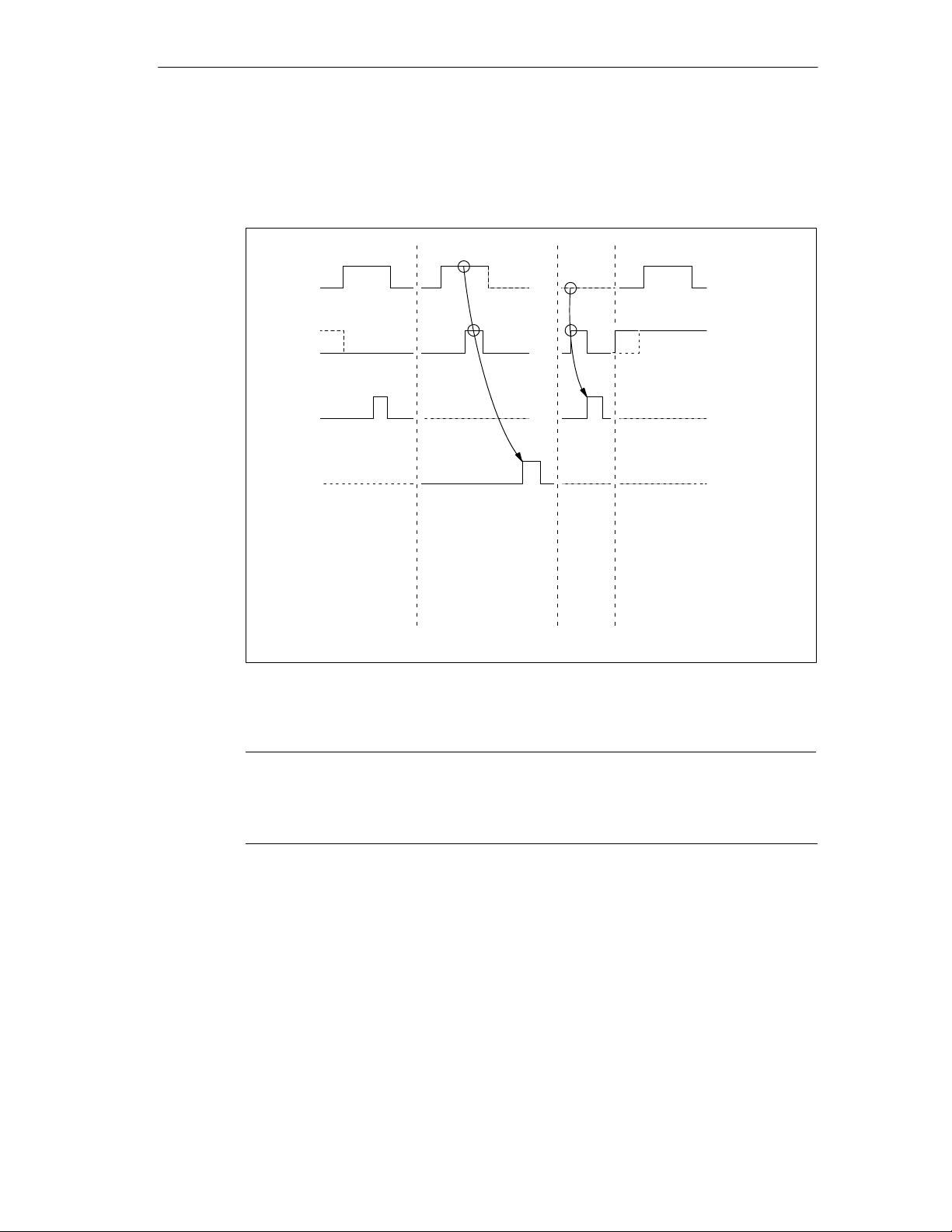
Time Sequence Chart for the SEND_440 FB
The figure below illustrates the behavior of the DONE and ERROR parameters,
depending on how the REQ and R inputs are wired.
REQ
R
DONE
ERROR
Communication Using Function Blocks
Sending job
Completion without errors
Figure 6-1 Time Sequence Chart for the 10 SEND_440 FB
1st /n. part of SEND
RESET transmitted
Completion with errors
RESET transmitted
Completion without errors
SEND job
not executed
(sending
deactivated)
Note
The REQ input is edge-triggered. A positive edge at the REQ input is sufficient. It
is not necessary for the RLO (result of logical operation) to be at “1” during the
whole transmission.
Point-to-point connection CP 440 Installation and Parameter Assignment
A5E00057742-02
6-9
Page 98

Communication Using Function Blocks
6.4.2 S7 Receives Data from a Communication Partner, 9 RECV_440 FB
The RECV_440 FB transmits data from the CP 440 to an S7 data area specified
by the DB_NO, DBB_NO and LEN parameters. The RECV_440 FB is called
cyclically for data transmission or, alternatively, statically in a time-controlled
program (without conditions).
With the (static) signal state “1” at the EN_R parameter, the check as to whether
data is to be read by the CP 440 is enabled. An active transmission can be aborted
with the signal state “0” at the EN_R parameter. The aborted receive job is
terminated with an error message (STATUS output). Receiving is deactivated as
long as the EN_R parameter has the signal state “0”. A data transmission can run
over several calls (program cycles), depending on the amount of data involved.
If the function block detects the signal state “1” at the R parameter, the current
send job is aborted and the RECV_440 FB is set to the initial state. Receiving is
deactivated as long as the R parameter has the signal state “1”.
The LADDR parameter defines the CP 440 to be addressed.
Error Display on the RECV_440 FB
The NDR output indicates that the job has been completed without errors (all data
read). ERROR indicates that an error has occurred. If there was an error, the
corresponding event number is displayed for STATUS (see Section 8.3). If there is
no error, STATUS = 0. NDR and ERROR/STATUS are also output when
RECV_440 FB is RESET (LEN == 16#00 parameter) (see Figure 6-2). In the event
of an error, the binary result BR is reset. If the block is terminated without errors,
the binary result has the status “1”.
Note
The RECV_440 function block does not have a parameter check. If there are
invalid parameters, the CPU branches to the STOP mode.
6-10
Point-to-point connection CP 440 Installation and Parameter Assignment
A5E00057742-02
Page 99

What To Do
Communication Using Function Blocks
Block Call
STL Representation LAD Representation
CALL RECV_440, I_RECV_440
RECV_440, I_RECV_440
EN_R: =
R: =
LADDR: =
DB_NO: =
DBB_NO: =
NDR: =
ERROR: =
EN ENO
EN_R NDR
R ERROR
LADDR LEN
DB_NO STATUS
DBB_NO L_TYP
LEN: =
STATUS: =
Note
The parameters EN and ENO are only present in the graphical representation
(LAD or FBD). The block is started with EN = TRUE. If the function is completed
without errors, ENO = TRUE is set. To process these parameters, the compiler
uses the binary result BR. The binary result is set to the signal state “1” if the block
was terminated without errors. If there was an error, the BR is set to “0”.
Assignment in the Data Area
The RECV_440 FB works with an instance DB (I_RECV_440). The DB number is
specified in the call. The data in the instance DB cannot be accessed.
Note
Exception: If the error STATUS == W#16#1E0E occurs, you can consult the
SFCERR variable for more details of the error (see Section 8.3). This error
variable can only be loaded via a symbolic access to the instance DB.
Point-to-point connection CP 440 Installation and Parameter Assignment
A5E00057742-02
6-11
Page 100

Communication Using Function Blocks
Parameters of the RECV_440 FB
The following table lists the parameters of the RECV_440 FB.
Table 6-3 Parameters of the RECV_440 FB
Name
Type Data Type Comment Permitted Values,
Comment
EN_R INPUT BOOL Enables reading of data
R INPUT BOOL Aborts job Current job is aborted. Receiving
is disabled.
LADDR INPUT INT Basic address of CP 440 The basic address can be found
in the configuration table in
STEP 7.
DB_NO INPUT INT Data block number Receive DB No.:
CPU-specific, zero is not
allowed
DBB_NO INPUT INT Data byte number Offset is CPU-specific
1
NDR
OUTPUT BOOL Job completed without
ST ATUS parameter == 16#00;
errors, data accepted
ERROR
1
OUTPUT BOOL Job completed with errors STATUS parameter contains
error details
1
LEN
STATUS
OUTPUT INT Length of message frame
received
1
OUTPUT WORD Specification of the error If ERROR == 1, STATUS
1 LEN 200, specified
in number of bytes
parameter contains error
information
1
The parameter is available until the next call of the FB!
6-12
Point-to-point connection CP 440 Installation and Parameter Assignment
A5E00057742-02
 Loading...