

Page 1
SIMATIC
Counter Module CM35
Manual Release 06/20 00
Page 2

Foreword, Table of Contents
User’s Information
CM35
Counter Module
Manual
This manual describes
the counter module with
order no. 6AT1 735-0AA01-0AA0
Product Overview
Function Description
Commissioning
Operating Modes
Data Communication with the
CM35
Pulse Counter Operating Mode
Period Duration Measurement
Operating Mode
Timer Operating Mode
Positioning Operating Mode
1
2
3
4
5
6
7
8
(4) J31069-D0416-U001-A5-7618
Appendices
Literature
EC Declaration of Conformity
Glossary
A
B
Release 06/2000
Page 3
Notes on safety
!
!
!
This manual contains notes which you must adhere to for your own personal safety and to
avoid property damage. These notes are highlighted with a warning triangle showing the
degree of danger as shown below.
Danger
Means death, severe personal injury or significant property damage will occur when the
appropriate precautionary measures are not taken.
Warning
Means death, severe personal injury or significant property damage may occur when the
appropriate precautionary measures are not taken.
Caution
Means minor personal injury or property damage may occur when the appropriate precautionary measures are not taken.
Note
Highlights important information about the product, its handling or a particular portion of
the documentation which requires special attention.
Qualified
personnel
Use as intended
!
Brands
Passing on tothird parties, reproduction, utilization and revelation of
this document is not permitted without express permission.Violators
will be liable for damages.All rights are reserved, in particular rights
created by a patent grant or registration of a utility model or design.
Siemens AG
Automation and Drives
Motion Control Systems
Frauenauracher Strasse 80
D-91056 Erlangen
Siemens Aktiengesellschaft
Only qualified personnel may commission and operate the device. For the purpose of the
safety notes in this manual, qualified personnel are those persons who are authorized to commission, ground and tag devices, systems and electrical circuits in accordance with safety
standards.
Adhere to the following.
Warning
The device may only be used for the individual applications included in the catalog and
technical description. When used with devices and components of other manufacturers,
these devices and components must be approved or recommended by Siemens.
Correct and safe operation of the product is dependent on proper transportation, storage,
setup and installation and careful operator control and maintenance.
SIMATICR is a registered brand of SIEMENS AG.
The other designations in this publication may be brands whose use by third parties may
violate the rights of the owners.
Disclaimer of liabilityCopyright E Siemens AG 1997--2000, All rights reserved
Although we have checked the contents of this manual for agreement with the hardware and software described, full agreement cannot be guaranteed. The information in this manual is checked at
regular intervals and necessary corrections included in the next
release.Your ideas and suggestions are welcome.
E Siemens AG 1997--2000
Subject to change without prior notice
Page 4

Foreword
Purpose of this
manual
Contents of this
manual
Target readers
Area of validity of
this manual
Hardware and software prerequisites
for this manual
This manual describes all steps required for the effective use of the CM35
counter module. It presents the functionality of the CM35 concisely and logically while you are familiarizing yourself with the module.
This manual describes the hardware and software of the CM35. It provides an
introduction and can also be used as a reference work.
This manual has been written for the following circles of readers.
S Maintenance personnel
S Programmers
S Commissioning personnel
S Service personnel
This manual describes the functions of the CM35 counter module as t hey
were at the time this manual was published. We reserve the right to modify
the functionality of the CM35. These c hanges will be described in product
information sheets.
This manual describes:
S The CM35 counter module (order no. 6AT1 735-0AA01-0AA0)
S The configuration package (order no. 6AT1 735-0DA01-0YA0)
If you are using the previous version of the CM35 counter module (order no.
6AT1 735-0AA00-0AA0), please use the configuration package with the order number 6AT1 735-0DA00-0YA0.
Caution:
The CM35 counter module (order no. 6AT1 735-0AA01-0AA0) is not com-
patible with the CM35 counter module (order no. 6AT1 735-0AA00-0AA0).
Additional source
of information
CM35 Counter Module
(4) J31069-D0416-U001-A5-7618
The appendix lists additional sources of information on the subject of
SIMATIC S7--300.
i
Page 5

For
eword
Aids to finding
information in this
manual
Standards
This manual offers the following aids to help you find the special information
you want.
S A comprehensive table of contents is located at the beginning of the
manual.
S All chapters provide a left--hand column with an overview of the contents
of the particular section.
S At the end of the manual, you will find a glossary defining important
terms as they are used in the manual.
The SIMATIC S7--300 programmable controller meets the requirements of
standard IEC 1131.
Contact your Siemens representative at your nearest Siemens office or the
SIMATIC hotline (telephone no. 0911/895-7000 or fax no. 0911/895-7002)
for questions on the products described in this manual for which you are unable to find answers.
For questions or comments on the manual itself, please fill out the response
sheet at the end of the manual, and return it to the address indicated. We
would also appreciate your including your personal opinion of the manual on
the response sheet.
We offer courses to make it easier to get started with the SIMATIC automation system. Please contact your regional training center or the central training center in Nuremberg (tel. no. 0911/895-3154).
ii
(4) J31069-D0416-U001-A5-7618
CM35 Counter Module
Page 6

Table of Contents
1 Product Overview 1-1.......................................................
1.1 Overview 1-2.......................................................
1.2 Use on Programmable Controllers and Automation
Systems 1-3.......................................................
1.3 Hardware 1-6......................................................
1.4 Software 1-8.......................................................
1.5 Technical Data 1-9..................................................
2 Function Description 2-1....................................................
2.1 Function Overview 2-2...............................................
2.2 Pulse Counter 2-3..................................................
2.3 Period Duration Measurement 2-3.....................................
2.4 Timer 2-3..........................................................
2.5 Positioning 2-3.....................................................
3 Commissioning 3-1.........................................................
3.1 Installation of the CM35 3-3..........................................
3.1.1 Mounting the CM35 3-3..............................................
3.1.2 Mounting and Demounting the CM35 3-6...............................
3.2 Wiring the CM35 3-8................................................
3.2.1 Connection Allocation of the 25--Pin Sub D Socket 3-10...................
3.2.2 Connection Allocation of the 15--Pin Sub D Socket 3-12...................
3.3 Configuration and Parameterization 3-13................................
3.3.1 Installation of the Object Manager for STEP 7 3-14.......................
3.3.2 Central Integration into the SIMATIC S7-300 3-15........................
3.3.3 Distributed Integration into the SIMATIC S7 3-16.........................
3.3.4 Distributed Integration into the SIMATIC S5 3-17.........................
3.3.4.1 Hardware Prerequisites 3-17..........................................
3.3.4.2 Configuration 3-18...................................................
3.4 Reactions during Startup and in Case of Errors 3-23......................
4 Data Communication with the CM35 4-1......................................
4.1 Overview 4-2.......................................................
4.2 Parameterization 4-3................................................
4.2.1 Parameterization with SFC 55 (Only SIMATIC S7) 4-6...................
4.2.2 Parameterization via Direct I/O Accesses (Only SIMATIC S5) 4-8..........
4.3 Programming 4-11...................................................
CM35 Counter Module
(4) J31069-D0416-U001-A5-7618
iii
Page 7

T
abl
s
e of Content
4.3.1 Controlling the Channels 4-11.........................................
4.3.2 Controlling the Digital Outputs 4-13.....................................
4.3.3 I/O Write Accesses 4-14..............................................
4.3.4 Reading the Data 4-15................................................
4.3.5 Evaluating a Hardware Interrupt in OB 40 4-17...........................
4.4 Overview of the Allocation of the Address Area and
Sequence of the Evaluation 4-19.......................................
5 Pulse Counter Operating Mode 5-1..........................................
5.1 Function Description 5-2.............................................
5.2 Parameterization 5-4................................................
5.2.1 Description of the Parameterization Data 5-4...........................
5.2.2 Structure of the Parameter Blocks 5-11.................................
5.3 Starting and Stopping the Counting Channels 5-14.......................
5.4 Controlling the Digital Outputs 5-15.....................................
5.5 Hardware Interrupt Evaluation 5-17.....................................
5.6 Reading the Counting Values 5-18.....................................
6 Period Duration Measurement Operating Mode 6-1............................
6.1 Function Description 6-2.............................................
6.2 Parameterization 6-4................................................
6.2.1 Description of the Parameter Data 6-5.................................
6.2.2 Structure of the Parameter Block 6-6..................................
6.3 Starting and Stopping the Measuring Channels 6-7......................
6.4 Controlling the Digital Outputs 6-8.....................................
6.5 Hardware Interrupt Evaluation 6-9.....................................
6.6 Reading the Measured Values 6-10.....................................
7 Timer Operating Mode 7-1..................................................
7.1 Function Description 7-2.............................................
7.2 Parameterization 7-3................................................
7.2.1 Description of the Parameter Data 7-4.................................
7.2.2 Structure of the Parameter Blocks 7-6.................................
7.3 Starting and Stopping the Timers 7-9..................................
7.4 Controlling the Digital Outputs 7-10.....................................
7.5 Hardware Interrupt Evaluation 7-12.....................................
7.6 Reading the Status 7-14..............................................
8 Positioning Operating mode 8-1.............................................
8.1 Function Description 8-2.............................................
8.2 Parameterization 8-7................................................
8.2.1 Description of the Parameter Data 8-8.................................
8.2.2 Structure of the Parameter Blocks 8-10.................................
iv
(4) J31069-D0416-U001-A5-7618
CM35 Counter Module
Page 8

T
abl
s
e of Content
8.3 Starting and Stopping the Axes 8-14....................................
8.4 Controlling the Digital Outputs 8-16.....................................
8.5 Hardware Interrupt Evaluation 8-18.....................................
8.6 Reading the Actual Positions 8-19......................................
A Literature A-1..............................................................
B EC Declaration of Conformity B-1............................................
Glossary Glossary-1..........................................................
CM35 Counter Module
(4) J31069-D0416-U001-A5-7618
v
Page 9

T
abl
s
e of Content
vi
(4) J31069-D0416-U001-A5-7618
CM35 Counter Module
Page 10

Product Overview
1
CM35 Counter Module
(4) J31069-D0416-U001-A5-7618
1-1
Page 11

r
oduct Overview
P
1.1 Overview
Function scope
Digital inputs and
outputs
Application areas
The CM35 is a multi--channel counter module which can be used to implement various tasks in the following operating modes.
S Pulse counter
S Period duration measurement
With 8 channels
S Timer
S Positioning With 4 axes
The selected operating mode applies to all channels of the CM35. The function parameters can be set separately for each channel.
The counter module has eight floating digital inputs and outputs which are
used for the inputs and outputs of the counting channels. The signals are led
out via two sub D sockets on the front.
When not used for the operating mode, the outputs can be used as desired by
the user program as process I/O.
The m odule can be used for position encoding and positioning as well as in
the following systems.
-- Proportioning systems
-- Filling systems
Use with programmable controllers
and automation
systems
-- Packaging systems
-- Sorting systems
-- Systems with defined time intervals
The counter module can be used centrally on the SIMATIC S7--300 and as
distributed I/O on the modular ET 200M I/O device on the SIMATIC S7 and
SIMATIC S5. The conventional configuration procedures of STEP 7 or
COM PROFIBUS (for SIMATIC S5) are used for the configuration.
1-2
(4) J31069-D0416-U001-A5-7618
CM35 Counter Module
Page 12
r
oduct Overview
P
1.2 Use on Programmable Controllers and Automation Systems
Central integration
into the
SIMATIC S7-300
Distributed integration into the
SIMATIC S7
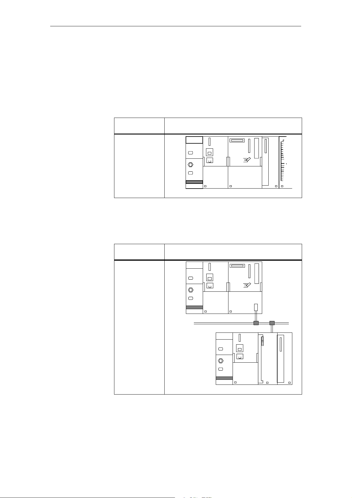
The full function scope of the module can be utilized. System function
SFC 55 is available for the parameterization. See reference manual /235/.
Possible
Modules
Example:
CPU 312 IFM
CPU 313
CPU 314
:
CPU 614
Sample Configuration
PS
CPU
CM35
The full function scope of the module can be utilized. Parameterization is
performed with system function SFC 55.
Possible
Modules
Master:
-- S7-CPU with
DP interface
-- CP 443-5 Ext.
-- IM 467
Sample Configuration
S7-300
CPU 315-2 DP
CM35 Counter Module
(4) J31069-D0416-U001-A5-7618
Slave:
-- IM 153-1
-- IM 153-2
PS
PROFIBUS-DP
ET 200M
PS CM35IM 153-1
1-3
Page 13
r
oduct Overview
P
Distributed integration into the
SIMATIC S5
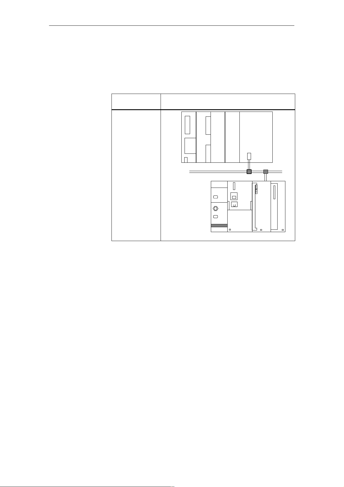
Since no hardware interrupts are triggered on the SIMATIC S5 by
PROFIBUS--DP, the function scope is limited. Only the operating modes
²period duration measurement² and ²timer² can be used.
Parameterization is performed via I/O direct accesses.
Possible
Modules
Master:
-- P L C
S5-95U(-MA)
-- PLC S5-115U
-- PLC S5-135U
-- PLC S5-155U
via IM 308-C
Slave:
-- IM 153-1
-- IM 153-2
Sample Configuration
IM 308-C
S5-115U
PROFIBUS-DP
ET 200M
IM 153-1
PS CM35IM 153-1
Prerequisites for the coupling are an IM 153--1 (MLFB no. 6ES7
153--1AA02--0XB0 or later) and CM35 modules (MLFB no. 6AT1
735--0AA01--0AA0, release status 4 or later).
Up to 7 CM35 modules can be connected with each IM 153--1 interface.
Exception: Maximum of one CM35 per IM 153--1 when distributed
connection to a SIMATIC S5--95U/master DP is used
Maximum of 8 CM35s per IM 153--1 when distributed
connectiontoaSIMATICS7(CPU318--2DP,
CPU 417--4 DP, CP 443--5 Ext., IM 467) is used
1-4
(4) J31069-D0416-U001-A5-7618
CM35 Counter Module
Page 14

r
oduct Overview
P
IM 153-2
SIMATIC S7-400H
and active backplane bus,
SIMATIC PCS 7
Prerequisites for the coupling are an IM 153--2 (MLFB no. 6ES7
153--2AA01--0XB0, release status 2 or later) and CM35 modules (MLFB no.
6AT1 735--0AA01--0AA0).
CM35 modules (MLFB no. 6AT1 735--0AA01--0AA0, release status 4 or
later) are required for the IM 153--2 interfaces (MLFB no. 6ES7
153--2AA02--0XB0, release status 5 or later).
Up to 7 CM35 modules can be connected to each IM 153--2 interface.
Exception: Maximum of one CM35 per IM 153--2 when distributed
connection to a SIMATIC S5--95U/master DP is used
Maximum of 8 CM35s per IM 153--2 when distributed
connectiontoaSIMATICS7(CPU318--2DP,
CPU 417--4 DP, CP 443--5 Ext., IM 467) is used.
The present version of the CM35 does not support:
S The setup with active bus modules for ET 200M
S Use on high--availability programmable controllers with redundant setup
(SIMATIC S7-400H)
S Use with SIMATIC PCS 7
For additional information, contact the SIMATIC hotline.
CM35 Counter Module
(4) J31069-D0416-U001-A5-7618
1-5
Page 15
r
oduct Overview
P
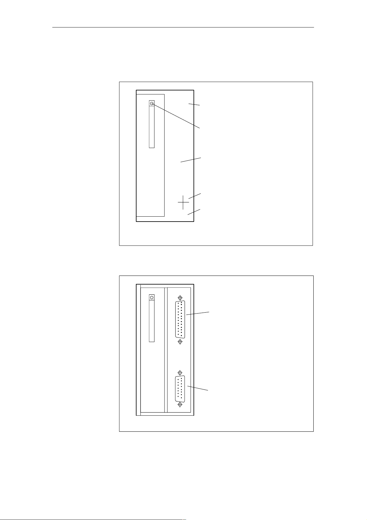
1.3 Hardware
View of the
module with
front door
closed
SF
CM35
Counter Module
x2
34
xxxxxxx
Module name
SF LED
Front door
Release status
Order number
(6AT1 735-0AA01-0AA0)
View of the
module with
front door
open
Figure 1-1 View of the front with front door closed
SF
Digital inputs
25-- pin sub D socket
Digital outputs
15-- pin sub D socket
Figure 1-2 View of the front with front door open
1-6
(4) J31069-D0416-U001-A5-7618
CM35 Counter Module
Page 16

r
oduct Overview
P
Front plug
connector
SF LED
The CM35 is equipped with the following front plug connectors for connection of the process I/O.
S 25--pin sub D socket for connection of the input signals (digital inputs)
The inputs are individually isolated from one another and can be used
with a 5 V or 24 V signal level.
S 15--pin sub D socket with digit al outputs and the connection for the exter-
nal supply voltage for the digital outputs
The outputs are isolated against the module logic, but are not isolated
among one another. They are powered with a supply voltage of 24 V DC.
The red SF LED on the front indicates that the module is not ready for operation. This LED goes off when a valid parameterization was transferred to the
module after a warm restart or hot restart and the BASP/OD signal is no longer active.
The CM35 does not support diagnostic alarms and the STEP 7 diagnostic
information.
CM35 Counter Module
(4) J31069-D0416-U001-A5-7618
1-7
Page 17

r
oduct Overview
P
1.4 Software
Module
firmware
The firmware of the module offers four different operating modes.
S Pulse counter
Continuous counting with maximum counting frequencies of 10 kHz
S Period duration measurement
Measurement of period durations between 1 msec and 2.6 sec with a resolution of 1% on all 8 channels (reference frequencies: 100 kHz, 50 kHz,
25 kHz)
S Timer
8 separate switch--on times from 10 msec to 278 min
S Positioning
31
4 axes with a max. of 2
2kHz
The desired operating mode is selected via the configuration user interface.
Note
The following applies when the CM35 is used to acquire frequencies.
increments up to a top frequency of
S For lower frequencies: ²period duration measurement² operating mode is
recommended (the pe r iod duration can be converted to a frequency).
S For higher frequencies: ²pulse counting² operating mode is recom-
mended.
Software
Depending on use on the SIMATIC S7 or decentralized on the SIMATIC S5,
configuration of the module is performed with the ²SIMATIC Manager² or
with ²COM PROFIBUS.²
1-8
(4) J31069-D0416-U001-A5-7618
CM35 Counter Module
Page 18
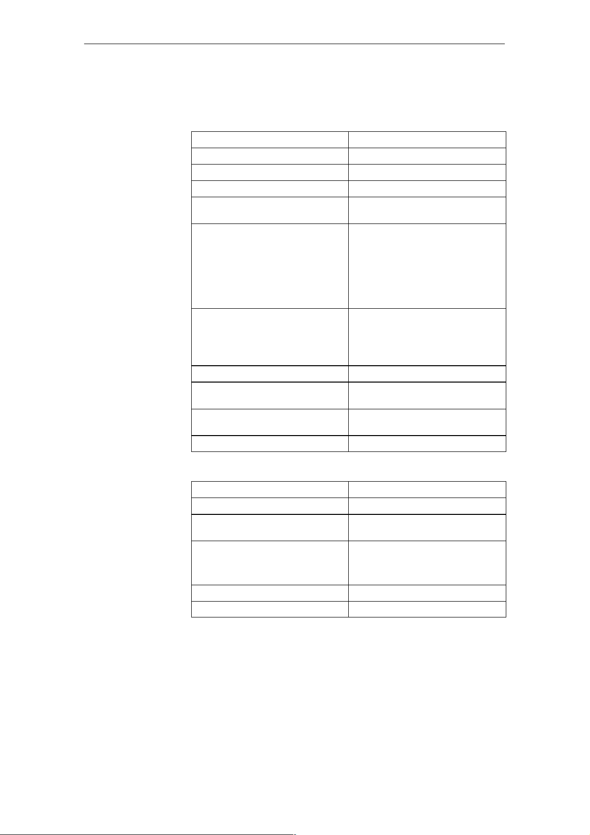
1.5 Technical Data
r
P
oduct Overview
Digital inputs
Type Pulse counter
Number 8
System Incremental
Limit frequency Max. of 10 kHz
Minimum pulse duration
(for high and low)
Signal level S 24 Volt signals:
40 msec
-- Signal
-- Signal
²H²:15to30Volt
²L²:-3to+5Volt
S 5 Volt signals:
-- Signal
-- Signal
Input current S For 24 V and ²H² signal
-- Typical 4.7 mA
²H²:2.4to6Volt
²L²: --0.6 to 0.8 Volt
S For 5 V and ²H² signal
-- Typical 10 mA
Potential isolation Yes
Maximum signal rise time From ²L² to ²H²: typ. 10 msec
From
²H² to ²L²: typ. 15 msec
Permissible cable length (shielded) For 24 V 25 m
For 5 V 5 m
Connection 25--pin sub D socket
Digital outputs
Number 8
Signal level 24 Volt, P--switching
Output current (short--circuit proof) Per DO: Max. of 0.5 A
Total current: Max. of 4 A
Switching frequency Max. of 10 Hz with ohmic load
8 Hz with lamp load
Max. of 0.5 Hz with inductive load
Cable length Max. of 100 m
Connection 15--pin sub D socket
CM35 Counter Module
(4) J31069-D0416-U001-A5-7618
1-9
Page 19

r
oduct Overview
P
Other
MLFB no.
Input voltage +5 V via P bus
Current consumption Typ. 0.150 A
UL/CSA/FM No
CM 35 counter module: 6AT1 735-0AA01-0AA0 or later
Configuration package: 6AT1 735-0DA01-0YA0 or later
1-10
(4) J31069-D0416-U001-A5-7618
CM35 Counter Module
Page 20

Function Description
2
CM35 Counter Module
(4) J31069-D0416-U001-A5-7618
2-1
Page 21

F
unction Description
2.1 Function Overview
Table 2-1 Operating modes
Operating
Function Limit
Mode
Pulse
counter
Counting up from
0 to 65535 with
comparison function
Counting down from
65535 to 0 with
comparison function
Period duration measurement
Measuring the time
between 2 falling
edges of the applied
signal
Timer Outputting the speci-
fied switching times
via the digital outputs
Positioning Acquiring the actual
position of axes via
incremental
encoder (track A/B)
and comparing it with
the setpoint
Fre-
quency
Control the
Digital
Outputs Via ...
Hardware
Interrupt
for ...
Use
on
S5 Master
or
Standard
Master
10 kHz Operating mode/
CPU control
Comparison
value
Not possible
is reached.
1kHz CPU control - Possible
- Operating mode/
CPU control
Expiration of
the
Possible
switch--on
time
2kHz Operating mode/
CPU control
Setpoint is
reached.
Not possible
2-2
(4) J31069-D0416-U001-A5-7618
CM35 Counter Module
Page 22

2.2 Pulse Counter
F
In this operating mode, the CM35 continuously counts up or down between 0
and 65535 when the counter is enabled.
-- When the counting value reaches the upper counting limit while
counting up and another pulse arrives, the counting value jumps to the
lower counting limit and counts from there without losing a pulse.
-- When the counting value reaches the lower counting limit while
counting down and another pulse arrives, the counting value j umps to
the upper counting limit and counts from there without losing a pulse.
2.3 Period Duration Measurement
In this operating mode, the CM35 acquires low frequencies with the aid of
period duration measurement.
The CM35 measures the e xact time between two falling edges of the counting signal by counting the pulses of an internal, precision--quartz reference
frequency.
unction Description
2.4 Timer
In timer operating mode, precisely defined switch-- on times of 10 milliseconds to 278 minutes can be implemented for every digital output.
2.5 Positioning
In this operating mode, the CM35 supports controlled positioning with a
switch--off point.
Position acquisition is performed with an incremental encoder whose pulses
are acquired by the module with the correct sign in the traversing area from
–2,147,483,648 to +2,147,483,647.
Two digital outputs are available for each of the four channels. These outputs are addressed by the CM35 based on the direction.
CM35 Counter Module
(4) J31069-D0416-U001-A5-7618
2-3
Page 23

F
unction Description
2-4
(4) J31069-D0416-U001-A5-7618
CM35 Counter Module
Page 24

Commissioning
This chapter provides all the information you will need for commissioning,
including mounting, connection, configuration and parameterizati on.
3
General safety
notes
!
!
Adherence to these safety notes is mandatory. Non--adherence will void the
warranty!
Warning
Unqualified manipulations on the device/system or non--adherence to the
warnings on the cabinet of the device/system can cause severe personal injury or property damage. Only qualified personnel may perform work on this
device/system.
Note
This device has been developed, manufac tured, tested and documented in
accordance with pertinent safety standards. Under normal conditions, the
device does not endanger property or human health.
Caution
Commissioning is prohibited until it has been determined that the machine in
which these components are to be installed meets the regulations of guideline 89/392/EWG.
CM35 Counter Module
(4) J31069-D0416-U001-A5-7618
3-1
Page 25

Commi
s
s
ioning
Note
The following rules must be adhered to ensure that EU guidelines
89/336/EWG have been met.
S The setup guidelines and safety notes in the manuals and supplementary
documentation must be adhered to for both the programmable controller
and the CM35.
S To achieve maximum EMC immunity, all signal lines to the CM35 must
be shielded and applied to a grounded shield retainer rail.
S On the CM35, the cable shield m ay not be applied to the sub D plug con-
nector.
3-2
(4) J31069-D0416-U001-A5-7618
CM35 Counter Module
Page 26

3.1 Installation of the CM35
s
s
3.1.1 Mounting the CM35
Commi
ioning
Preparation
Slot
Before physical installation is begun, the appropriate safety precautions must
be taken and the following points complied with or clarified.
S Was the module still in its original packaging?
S Check the delivery for transportation damages.
S Check the delivery for completeness.
If you discover damages or deficiencies, please contact
your SIEMENS representative.
The S7 interface of the CM35 corresponds to the serial I/O bus (P bus) of
the SIMATIC S7-300.
All slots on the SIMATIC S7 which can be assigned to signal modules (SM)
are available to the CM35.
For additional information, see the manual of the SIMATIC S7--300.
The maximum numbe r of CM35 modules which can be installed on SIMATIC programmable cont rollers depends on the following fac tors.
S Maximum number of modules in the central rack/expansion unit or the
modular ET 200M I/O device
S Memory requirements of the S5/S7/C7 CPU
S Maximum permissible current consumption (5 V) from the S7 backplane
bus
Physical
setup
Installation
position
CM35 Counter Module
(4) J31069-D0416-U001-A5-7618
For information on possible physical setups and how to configure, see
manual /70/.
Horizontal installation is recommended. When vertical installation is used,
remember that environmental temperatures are restricted (max. of 40° C).
3-3
Page 27
100
0mA
A
ET200Mwit
h
p
DPmaste
r
Commi
s
s
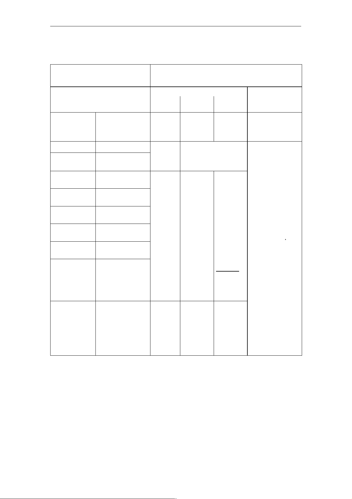
Table 3-1 Technical data of the SIMATIC
Type of Setup Central Setup Distributed Setup
CPU Work memory of the
CPU 312 IFM 6 8MOD No multi--row setup possible 7 MOD per ET 200M
CPU 313 12 800 m
CPU 314 24 8MOD 8+8MOD 1 · 8MOD
ioning
CPU
in Kbytes
(status 6/2000)
Number of Modules Which Can Be Installed on the Central Rack/Expansion Unit
Current (5 V) from the S7 Backplane Bus
1-row 2-row Max. of
4-row
Central rack IM 365 1 · IM 360
3 · IM 361
ET 200M
CPU 314 IFM 32
CPU 315 48
CPU 315-2 DP 64
CPU 316 128
CPU 318-2 DP 512,
of these max. of
256 for code
256 for data
CPU 31X-2 DP
CPU 41X-X DP
C7-6XX DP
S5-1X5U with
IM 308-C
MOD = CM35 modules
Depends on the CPU
being used
1200 mA To tal of
1100 mA
- - -
1 · 850 mA
plus
3 · 8MOD
3 · 800 mA
Exception:
With CPU
314 IFM:
Total of up t o
31 modules
Exceptions:
Max. of 8 MOD per
:
- CPU 318-2 DP
- CPU 417-4 DP
- CP 443-5 Ext.
- IM 467
Max. of 1 MOD per
ET 200M with:
SIMATIC S5-95U/
DP master
The number of slave
stations (ET 200M) per
CPU depends on the
CPU being used.
Example:
CPU 315-2 DP: Max.
of 32 slave stations
(ET 200M) per CPU
3-4
(4) J31069-D0416-U001-A5-7618
CM35 Counter Module
Page 28

Commi
s
s
Table 3-2 Requirements on the CM35 side
ioning
With Use of Current requirements (5 V) from
S7 Backplane Bus
m · CM35 m · 150 mA
m = Number of CM35 modules
CM35 Counter Module
(4) J31069-D0416-U001-A5-7618
3-5
Page 29

Commi
s
s
ioning
3.1.2 Mounting and Demounting the CM35
Rules
Required tools
No special protective measures (ESD guidelines) are required for installation
of the CM35.
You will need a 4.5 mm screwdriver to mount and de mount the CM35.
Note
Make absolutely sure that cable installation meets EMC regulations (also
inside the cabinets).
Avoid installing cables next to power cables, and shield the cables in the
manner described above.
Two--sided shield application is usually recommended. When interference is
primarily low--frequency, one--sided shield application can be more advantageous.
Adhere to the grounding concept of the SIMATIC S7--300 to avoid problems
with potential.
The setup guidelines (AR) of the SIMATIC S7 (see manual on setting up
S7--300 programmable controllers and CPU data) must be adhered to during
all mounting steps, and the following instructions must be performed in the
order specified.
3-6
(4) J31069-D0416-U001-A5-7618
CM35 Counter Module
Page 30

Commi
s
s
ioning
How to install
How to remove/
replace modules
For how to mount the modules on the system, see manual /70/ or /140/.
A simplified version of installation is given here.
1. Turn off all voltages on the SIMATIC S7, secure against switch--on, and
label.
2. Make protective conductor connection, or check it. See AR.
3. Mount shield connecting element (SAE).
-- The shield connecting element must be mounted directly under the
slot of the CM35 on the mounting rail.
-- Each cable to be connected to the CM35 requires a shield clamp on
the shield rail of the SAE.
4. Plug in bus connector. See AR.
-- A bus connector is supplied with each CM35. Insert the bus connector
on the module occupying the slot to the left of the CM35.
5. Hang in CM35. See AR.
6. Secure CM35 with screw. See AR.
7. Label CM35. See AR.
For how to set up/replace modules in the system, see manual /70/ or /140/.
A simplified version of removal is given here.
1. Switch the CPU to STOP.
2. Turn off the power supply.
3. Release the front plug connector, and disconnect it.
4. Release the mounting screw on the module.
5. Swivel the module out of the mounting rail, and re move it.
6. If necessary, install the new module.
For more information on removing the modules, see manuals /70/ and /140/.
CM35 Counter Module
(4) J31069-D0416-U001-A5-7618
3-7
Page 31
Commi
s
s
ioning
3.2 Wiring the CM35
Digital inputs
Digital outputs
Shield clamps
The 8 counting inputs (channels) of the CM35 are availa ble on a 25--pin sub
D socket on the front of the module.
Each counting input has separate connections for reference pote ntial
(ground), and 5 V and 24 V signals. To prevent malfunctions, only one of the
two signal voltages may be wired at a time.
The encoder must be powered by an external voltage source.
The 8 outputs of the CM35 are available on a 15--pin sub D socket on the
front of the module. A load power supply of 24 V DC must also be connected
there which is able to continuously supply the sum of the required output
currents.
The outputs are P switches which can handle a load current of 0.4 A. They
are protected against overload and short circuits.
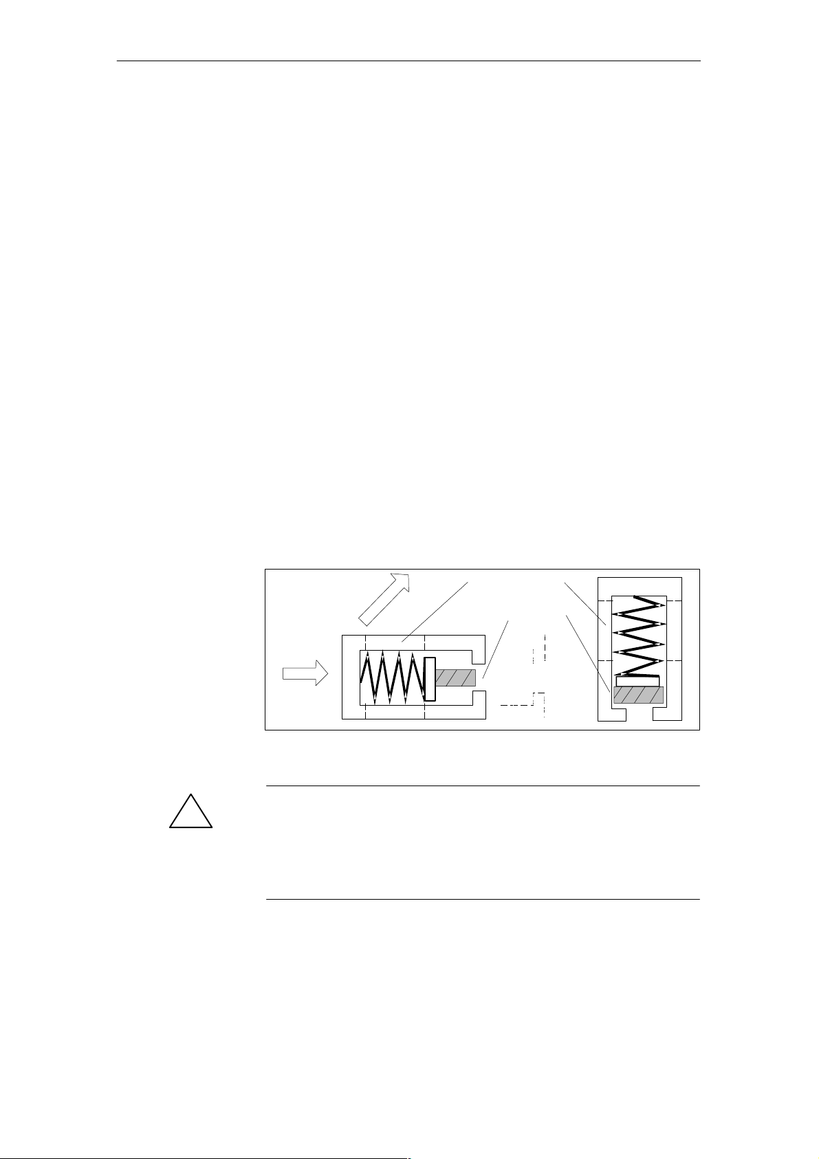
The size of the shield clamp depends on the diameter of the cable.
To mount a cable with the shield clamp, bare the shield by cutting out
approximately 1.5 cm of the cable insulation at the appropriate location on
the cable.
2
Shield clamp
Shield rail
(fixed)
1
Figure 3-1 Mounting the shield clamps
Caution
!
Do not damage the braiding of the shield when baring the cable.
When applying the shield to all cables connected to the CM35, remember to
leave enough cable between the shield connecting element and the CM35 so
that the CM35 can be removed with all cables connected.
3-8
(4) J31069-D0416-U001-A5-7618
CM35 Counter Module
Page 32
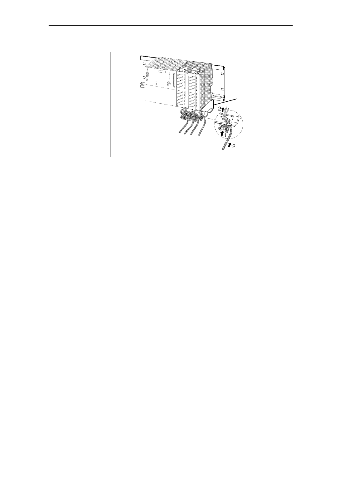
Figure 3-2 Shield connecting element
s
s
Commi
ioning
Shield connecting
element
CM35 Counter Module
(4) J31069-D0416-U001-A5-7618
3-9
Page 33
Commi
s
s
ioning
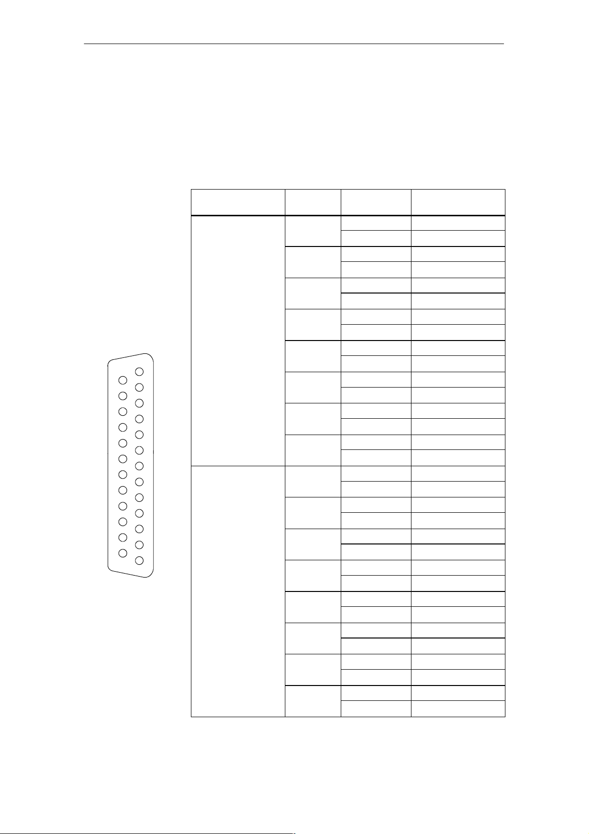
3.2.1 Connection Allocation of the 25-- Pin Sub D Socket
Wiring of the operating modes pulse
counter,
period duration
measurement and
timer
13
25
14
1
The i nputs must be wired in accordance with table 3-3 for modes pulse
counter, period duration measurement and timer.
Table 3-3 Wiring
Signal Voltage
5V 1 Counting pulse 20
24 V 1 Counting pulse 1
Channel Encoder
Signal
Ground 14
2 Counting pulse 2
Ground 21
3 Counting pulse 9
Ground 3
4 Counting pulse 16
Ground 10
5 Counting pulse 23
Ground 17
6 Counting pulse 5
Ground 24
7 Counting pulse 12
Ground 6
8 Counting pulse 19
Ground 13
Ground 14
2 Counting pulse 8
Ground 21
3 Counting pulse 15
Ground 3
4 Counting pulse 22
Ground 10
5 Counting pulse 4
Ground 17
6 Counting pulse 11
Ground 24
7 Counting pulse 18
Ground 6
8 Counting pulse 25
Ground 13
Connection to Pin ...
3-10
(4) J31069-D0416-U001-A5-7618
CM35 Counter Module
Page 34
Commi
s
s
ioning
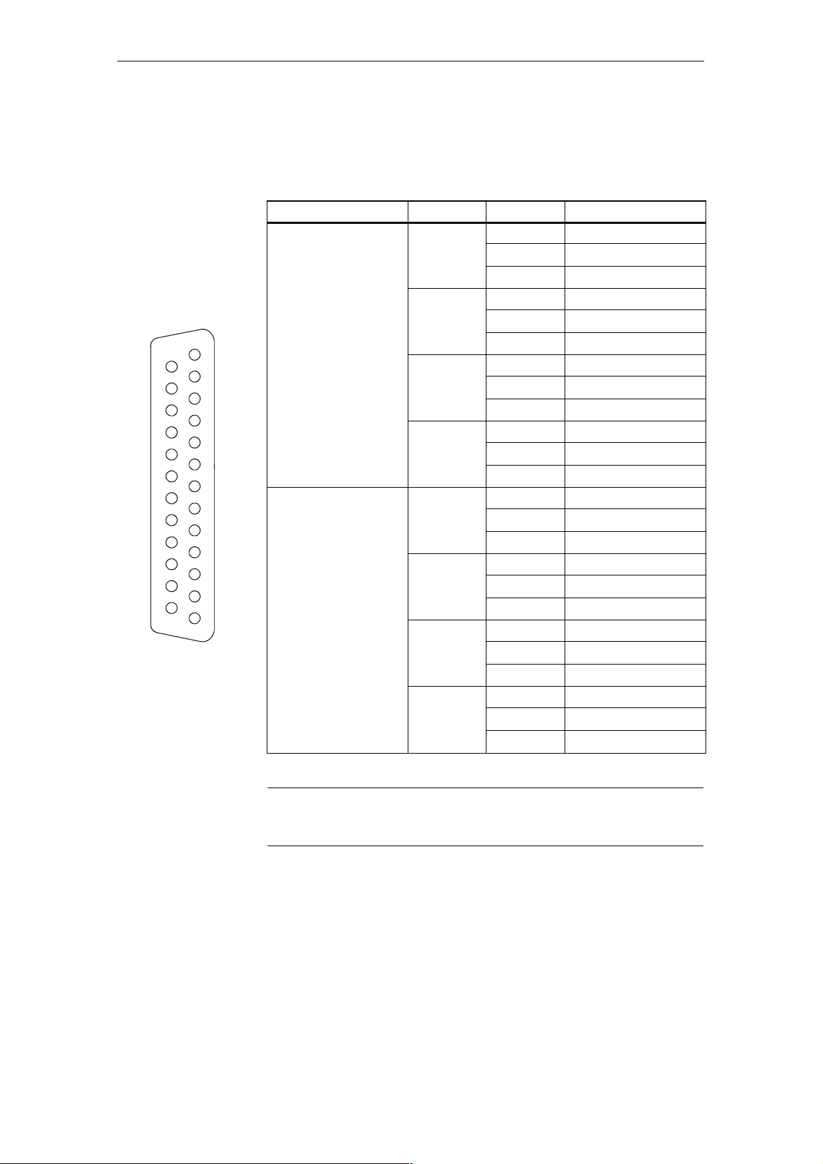
Wiring for operating mode
positioning
13
25
14
1
When ²positioning² mode is used, the inputs must be wired in accordance
with table 3-4.
Table 3-4 Wiring for ²positioning² operating mode
Signal Voltage
5V 1 A 20
24 V 1 A 1
Axis Tr ack Connection to Pin ...
B 2
Ground 14 / 21
2 A 9
B 16
Ground 3/10
3 A 23
B 5
Ground 17 / 24
4 A 12
B 19
Ground 6/13
B 8
Ground 14 / 21
2 A 15
B 22
Ground 3/10
3 A 4
B 11
Ground 17 / 24
4 A 18
B 25
Ground 6/13
Note
Connect the two ground connections for an axis.
Example of an encoder connection
-- Incremental encoder with 5 V supply
-- A x i s 1
Þ Track A: Pin 20
Track B: Pin 2
Ground: Pin 14 + pin 21 (connect t hese two)
CM35 Counter Module
(4) J31069-D0416-U001-A5-7618
3-11
Page 35
Commi
s
s
ioning
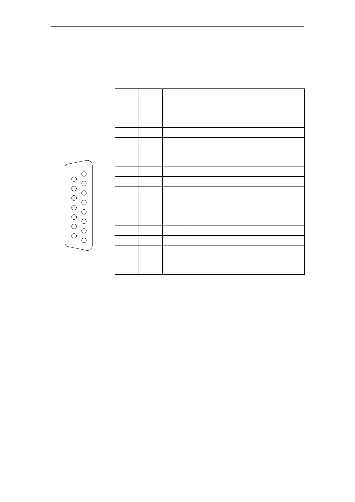
3.2.2 Connection Allocation of the 15-- Pin Sub D Socket
Table 3-5 Allocation of the 15 --pin sub D socket
15
14
Pin
1 VCC1 IN Load voltage 24 V
2 VCC1 IN Load voltage 24 V
3 O1 OUT Digital output 1 Axis 1, forwards
4 O2 OUT Digital output 2 Axis 1, backwards
8
1
5 O3 OUT Digital output 3 Axis 2, forwards
6 O4 OUT Digital output 4 Axis 2, backwards
7 GND 2 IN Ground load voltage for digital outputs
8 GND 2 IN Ground load voltage for digital outputs
9 VCC1 IN Load voltage 24 V
10 VCC1 IN Load voltage 24 V
11 O5 OUT Digital output 5 Axis 3, forwards
12 O6 OUT Digital output 6 Axis 3, backwards
13 O7 OUT Digital output 7 Axis 4, forwards
14 O8 OUT Digital output 8 Axis 4, backwards
15 GND 2 IN Ground load voltage for digital outputs
Signal Input/
Output
Pulse Counter,
Period Duration
Measurement,
Timer
Function for Mode
Positioning
The connections for 24 V load voltage and for ground load voltage are connected internally.
3-12
(4) J31069-D0416-U001-A5-7618
CM35 Counter Module
Page 36
Commi
s
s
3.3 Configuration and Parameterization
Configuration and parameterization of the CM35 depends on the system on
which the module is to be used.
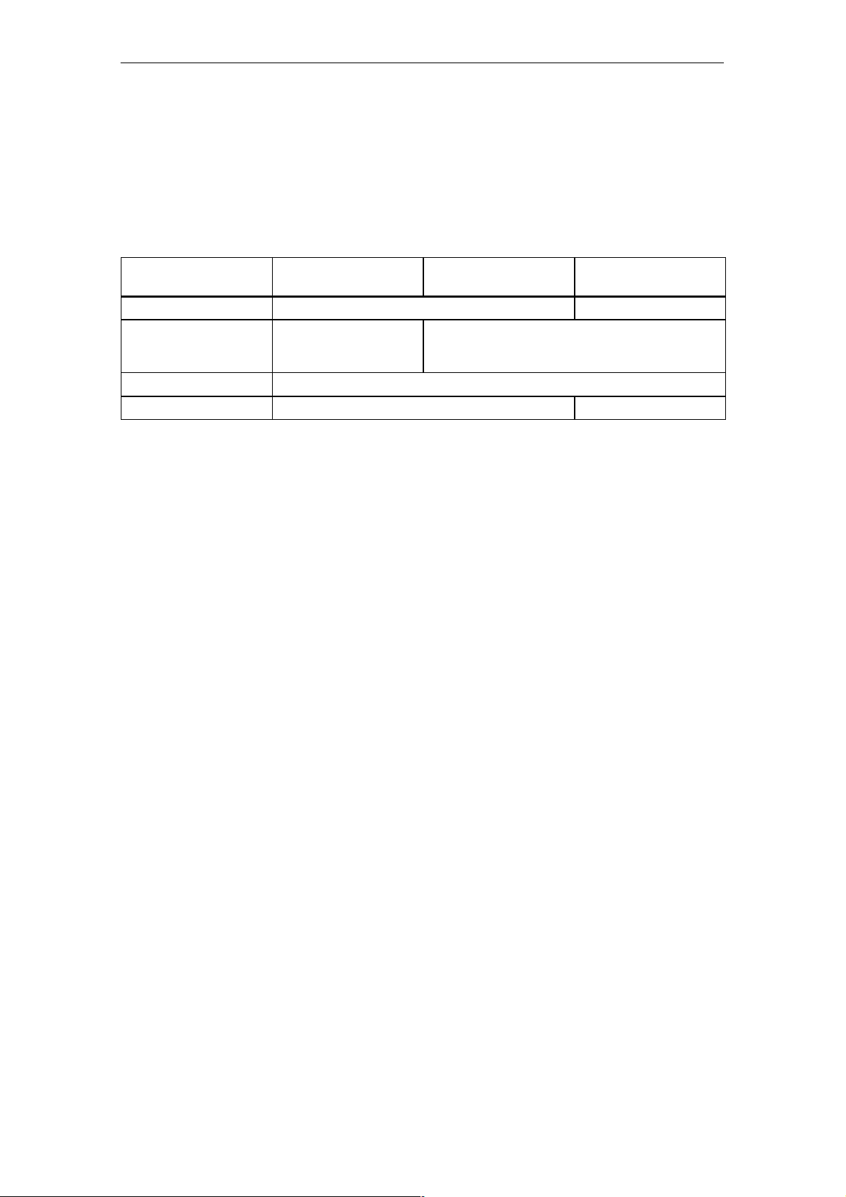
Table 3-6 Overview of configuration and parameterization
ioning
Central Integration into
the SIMATIC S7-300
Configuration tool STEP 7, HW Config COM PROFIBUS
Module address Depends on slot or selecta-
ble as desired
(depends on CPU)
Setting the operating mode During configuration
Parameterization With SFC 55 “WR_PARM” Via I/O direct accesses
Configuration with
STEP 7
The object manager from the included data medium must be installed first
(see chapter 3.3.1) so that STEP 7 will be able to recognize the CM35 during
Distributed Integration
into the SIMATIC S7
Can be selected as desired
Distributed Integration
into the SIMATIC S5
configuration.
Configuration with
COM PROFIBUS
Parameterization
The current GSD files must be loaded to subdirectory GSD so that
COM PROFIBUS is able to recogniz e the CM35 during configuration.
Parameterization is performed by the user program and only refers to the operating mode which was set when the module was configured.The required
parameters depend on this operating mode.
The fundamentals of parameterization are described in chapter 4.2.
For details, see the de scriptions of the individual operating modes.
CM35 Counter Module
(4) J31069-D0416-U001-A5-7618
3-13
Page 37
Commi
s
s
ioning
3.3.1 Installation of the Object Manager for STEP 7
Prerequisites
Installing the
object manager
Configuring the
hardware
To install the object manager (OM), STEP 7 (starting with V3.2) must be
installed correctly on your PG/PC.
To install the object manager, proceed as shown below.
1. Make sure that no applications are open in Windows.
2. Insert the data medium.
3. Call the SETUP.EXE program.
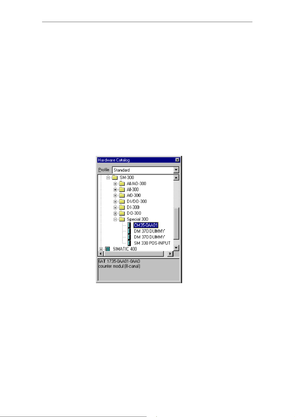
The CM35 counter module is located in the path shown below under STEP 7
! HW Config ! Catalog.
Figure 3-3 Counter module CM35 in the hardware catalog
Indicating
integrated help
In addition to the dialogs of the object manager, help information is available
which you can call during every phase of parameterization either with the F1
key or with the Help button.
3-14
(4) J31069-D0416-U001-A5-7618
CM35 Counter Module
Page 38

Commi
s
s
3.3.2 Central Integration into the SIMATIC S7-300
ioning
Configuration
Module
address
Setting the
operating mode
When used with an S7--300, the module is configured with STEP 7 with the
application HW Config. To add a CM35 to an existing project, proceed as
shown below.
1. Start the SIMATIC Manager, and open the desired project.
2. In the left--hand portion of the project screen, select the SIMATIC 300
station to which you want to add the CM35.
3. Select the menu command Edit > Open Object.
This opens the HW Config application. This application contains a screen
with the hardware setup of the opened station.
4. Select the CM35 from the module catalog of HW Config, and place it in
the module rack.
Based on its position on the mounting rail, the required input and output address areas are automatically assigned to the CM35 and entered in the confi guration table.
When certain CPUs are used, these address areas can be changed. For details, see manual /70/.
The operating mode of the CM35 must have already been set during the configuration. Proceed as shown below.
Commissioning
1. In the configuration table, select the line with the CM35, and select the
menu command Edit > Object Properties.
2. In the dialog box, open the tab Operating Mode, select the desired oper-
ating mode, and confirm with OK.
For additional details on preparation for operation, see manual /70/ and user
manual /231/.
CM35 Counter Module
(4) J31069-D0416-U001-A5-7618
3-15
Page 39

Commi
s
s
ioning
3.3.3 Distributed Integration into the SIMATIC S7
Configuration
Module
address
The module is configured as distributed I/O with the HW Config application
of STEP 7. To add a CM35 to an existing project, proceed as shown below.
1. Start the SIMATIC Manager, and open the desired project.
2. In the left--hand portion of the project screen, select the SIMATIC station
from which the DP slave is to be addressed.
3. Select the menu command Edit > Open Object.
This opens the HW Config application. This application contains a screen
with the hardware setup of the opened station.
4. If not already done, set up a DP slave. From the ²Hardware Catalog²
screen, select an ET 200M with IM 153-2, and place it in a PROFIBUS--DP master system.
5. Select the CM35 from the hardware catalog, and place it in the ET 200M.
Based on the position on ET 200M, the required input and output address
areas are automatically assigned to the CM35 and entered in the configuration table. Address gaps in the address areas of the CPU rack are utilized.
The preset address areas can be changed in accordance with certain rules.
For more information on free address assignment, see manual /70/. Proceed
as shown below.
1. In the configuration table, select the line with the CM35, and select the
menu command Edit > Object Properties.
Setting the
operating mode
Commissioning
2. In the indicated dialog box, open the t ab Addresses, and enter the desired
start address.
If there are address overlaps with other modules, you will be told this
when you close the dialog box.
3. Leave the dialog box open so that you can make the following settings of
the module’s operating mode.
The operating mode of the CM35 must have already been set during configuration. Proceed as shown below.
1. If not already done, select the line with the CM35 in the configuration
table, and select the menu command Edit > Object Properties.
2. In the dialog screen, open the tab Operating Mode, select the desired
operating mode, and confirm with OK.
For additional preparations before operation, see manual /70/ and user
manual /231/.
3-16
(4) J31069-D0416-U001-A5-7618
CM35 Counter Module
Page 40

Commi
s
s
3.3.4 Distributed Integration into the SIMATIC S5
Note
This section assumes that you have a knowledge of SIMATIC S5 and
COM PROFIBUS.
ioning
Integration on the
SIMATIC S5
The CM35 module can be linked as distributed I/O to the SIMATIC S5 using
PROFIBUS--DP.
The modular ET 200M I/O device is required to link the CM35 modules t o
PROFIBUS--DP. The SIMATIC S5 is connected to PROFIBUS--DP with interface IM 308--C. Another method is to use a SIMATIC S5--95U/DP master
with integrated PROFIBUS--DP interface.
3.3.4.1 Hardware Prerequisites
IM 308-C
Release 4 or later
Note
An FB 192 with release 3 can only be used with an IM 308--C starting with
release 6!
When release status 2 of the FB 192 is used, all versions of the IM 308-C
can be used starting with release status 3.
S5-95U/master DP
Release 2 or later
The maximum tra nsmission speed is 9600 Kbaud to 1.5 Mbaud, depending
on the length of the cable.
IM 153-1
Prerequisites for the coupling are an IM 153--1 (MLFB no. 6ES7
153--1AA02--0XB0 or later) and CM35 modules (MLFB no. 6AT1
735--0AA01--0AA0, release status 4 or later)
IM 153-2
Prerequisites for the coupling are an IM 153--2 (MLFB no. 6ES7
153--2AA01--0XB0, release status 2 or later) and CM35 modules (MLFB no.
6AT1 735--0AA01--0AA0).
CM35 modules (MLFB no. 6AT1 735--0AA01--0AA0, release status 4 or
later) are required for the IM 153--2 interfaces (MLFB no. 6ES7
153--2AA02--0XB0, release status 5 or later).
CM35 Counter Module
(4) J31069-D0416-U001-A5-7618
3-17
Page 41
Commi
s
s
ioning
3.3.4.2 Configuration
COM PROFIBUS
The IM 308-C interface module or S5-95U/DP master is parameterized with
the COM PROFIBUS software. With more recent versions of COM
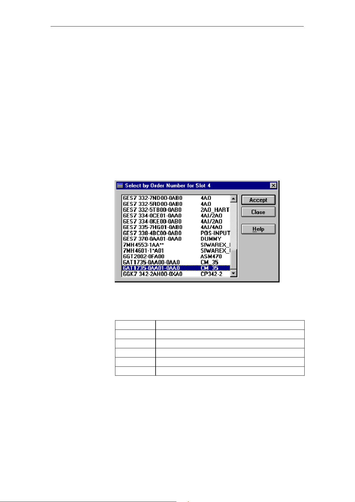
PROFIBUS, you should be able to find the CM35 module in the ET 200M
under its order number 6AT1 735-0AA01-0AA0. See figure 3-4.
If you cannot find the CM35, copy the type or GSD files from the configuration package to the appropriate direc tory of COM PROFIBUS. Which files
must be copied depends on the version of COM PROFIBUS.
S With COM PROFIBUS (version £ 3.2): Copy the type files to the direc-
tory ²TYPDAT5X.²
S With COM PROFIBUS (version ³ 3.3): Copy the GSD files to the direc-
tory ²GSD.²
Figure 3-4 Selecting the CM35 module during configuration of the ET 200M
Table 3-7 Type and GSD files
File Name
SI801DV*.200 Type file for IM 153-1
ST801EU*.200 Type file for IM 153-2
SIM801D.GS* GSD file for IM 153-1
SIM801E.GS* GSD file for IM 153-2
SIM8071.GS* GSD file for IM 153-2 FO
* Identifies the particular language version
Use
3-18
(4) J31069-D0416-U001-A5-7618
CM35 Counter Module
Page 42

Commi
s
s
ioning
Note
The latest GSD files (only for COM PROFIBUS version ³ 3.3) can be down-
loaded from the Internet (SIMATIC Customer Support).
Internet address: http://www.ad. siemens.de/support/html_00/index.shtml
Copy the new GSD files to the ²GSD² directory, and execute the menu command ²File > Open GSD File.²
Using the GSD files included with the configuration package has a drawback
-- you will not be using the latest GSD file (e.g., you may not be able to find
other new modules).
The type files are only required for older COM PROFIBUS
versions £ 3.2. In the future, they will be completely replaced by the
GSD files.
Configuration
Module
address
The module is configured as distributed I/O on the SIMATIC S5 with
COM PROFIBUS.
To add a CM35 to an existing DP master system, proceed as shown below.
1. Start COM PROFIBUS, and open the desired master system.
2. Open a DP slave (ET 200M with IM 153-1), or set up a new one.
3. Place the module in the ET 200M. In the configuration table, select the
desired slot, and select the button Order No. ...
In the dialog box ²Select...,² select the order number of the CM35
(6AT1 735-0AA01-0AA0), and select the Accept button.
4. Leave the configuration table open t o set the addresses and operating
mode which come next.
You can specify a start address for the input and for the output area. This address depends on the operating mode you want to use.
S Direct process inputs and outputs: Addresses in the P or Q area
Accesses only permitted via word load and transfer operations
S Accesses via FB 192: No address specifications required
For a detailed description of FB 192 and its manual, see the manual of
COM PROFIBUS.
Address overlapping with other modules or conflicts with reserved areas are
indicated by COM PROFIBUS.
CM35 Counter Module
(4) J31069-D0416-U001-A5-7618
3-19
Page 43
Commi
s
s
ioning
Module
address (for
use of
the IM 308-C)
The same start address is used for the input area and for the output area. The
CM35 module occupies 16 bytes in the input area and 16 bytes in the output
area. The module address must be a whole number multiple of 16. The start
address is also required for configuration under COM PROFIBUS.
Addressing in the process image (PY0 to PY127) should never be used for
consistent data.
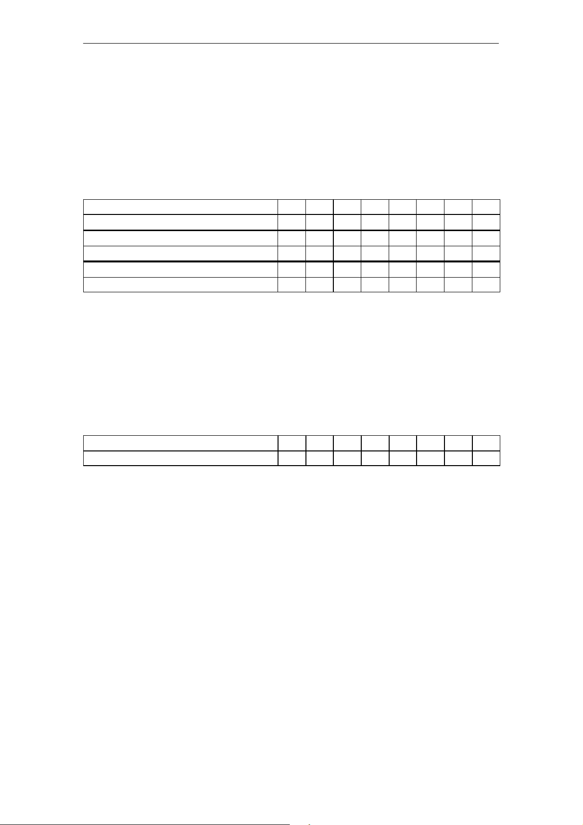
Table 3-8 Possible addresses
CM35 number
Possible CM35 addresses P: 128 144 160 176 192 208 224 240
CM35 number 9 10 11 12 13 14 15 16
Possible CM35 addresses Q: 0 16 32 48 64 80 96 112
CM35 number 17 18 19 20 21 22 23 24
Possible CM35 addresses Q: 128 144 160 176 192 208 224 240
1)
A fixed relationship between CM35 number and address does not exist.A maximum of 24 CM35 modules can be addressed per IM 308--C interface.
Module
address (for
use of
the S5-95U/DP)
1)
Input/output bytes 64 to 127 are used for both the local I/O (e.g., analog input/output modules, slots 0 to 7) and the distributed I/O (DP slaves). When
the local I/O is used (e.g., analog input/output modules), the address areas
must be reserved in the host parameters by the user with COM PROFIBUS.
1 2 3 4 5 6 7 8
Table 3-9 Possible addresses
CM35 number
Possible CM35 addresses P: 64 80 96 112 128 144 160 176
1 2 3 4 5 6 7 8
3-20
(4) J31069-D0416-U001-A5-7618
CM35 Counter Module
Page 44
Commi
s
s
ioning
Setting the
operating mode
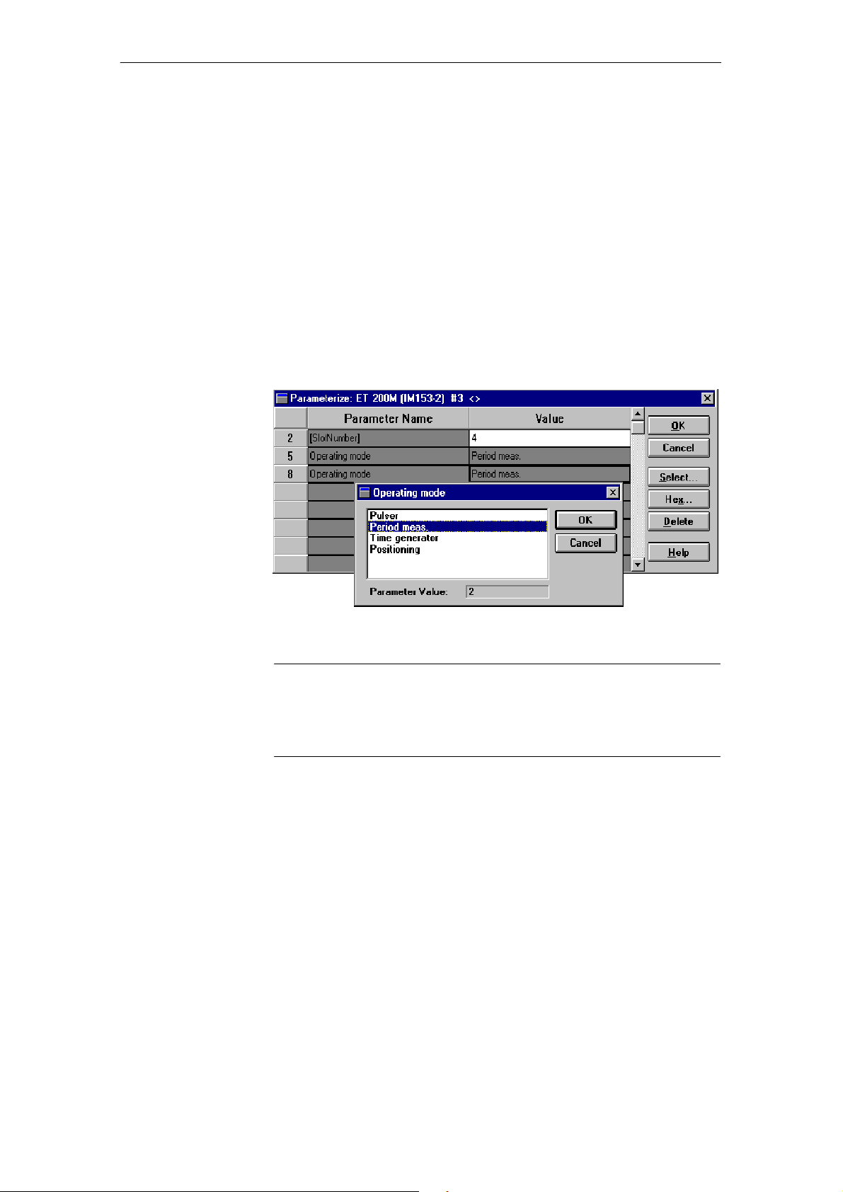
The operating mode of the CM35 must have already been set during configuration. Proceed as shown below.
1. In the configuration table, select the line with the CM35, and click the
button Param. ...
2. In the dialog box ²Parameterize...,² select the field under ²Value ² in the
first line of the table (5), and click the Select... button. In the next dialog
box which appears, select the desired operating mode, and confirm with
OK.
3. Repeat this step in the second line of the table (8) with the same operating
mode. See figure 3-5.
4. In the ²Parameterize...² dialog box, click the OK button, and close the
configuration table with OK.
Commissioning
Figure 3-5 Setting the operating mode with COM PROFIBUS
Note
When distributed integration into the SIMATIC S5 is used, only the operating modes ²period duration measurement² and ²timer² (time generator) are
permitted. See chapter 1.2.
For additional preparations before operation, see the manual of COM PROFIBUS.
CM35 Counter Module
(4) J31069-D0416-U001-A5-7618
3-21
Page 45
Commi
s
s
ioning
Data consistency
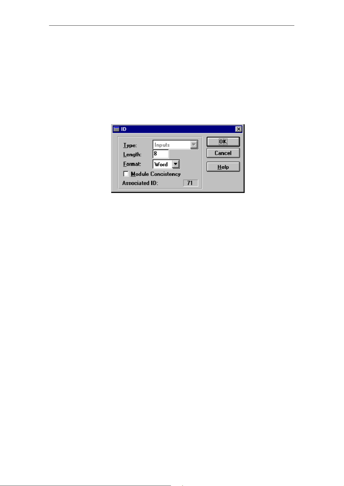
When the distributed integration is used, data consistency must be considered. Data are called consistent when their contents belong together.
When you access the CM35 with load/transfer commands, only word accesses may be used and only even addresses may be accessed so that consistency is ensured.
Data consistency is specified via the COM PROFIBUS configurat ion. Word
consistency has already been set for the CM35 in the type or GSD files included in the configuration package.
Figure 3-6 Setting of the consistency via COM PROFIBUS
For more information, see the manual on the distributed I/O system ET 200.
3-22
(4) J31069-D0416-U001-A5-7618
CM35 Counter Module
Page 46

Commi
s
s
ioning
3.4 Reactions during Startup and in Case of Errors
Warm restart
Hot restart
Reaction to failure
of the S7-300
Module power
supply
When a warm restart (power on) takes place, the red group error LED (SF)
on the front of the module stays on until the module is ready for operation
(i.e., until it has received valid parameters).
When the module firmware recognizes the CPU STOP stat e, the parameters
stored on the CM35 lose their validity. Parameter memory and the input and
output area are deleted. This is indicated by the group error LED.
When the CPU assumes the STOP state , running operation of the CM35 is
terminated. The digital outputs are switched off (i.e., reset). Although the
operating mode is retained, the parameters are no longer valid.
Since the CM35 is completely powered by the backplane bus of the
SIMATIC S7-300, it has to be switched on together with the S7--300 CPU or
IM module.
CM35 Counter Module
(4) J31069-D0416-U001-A5-7618
3-23
Page 47

Commi
s
s
ioning
3-24
(4) J31069-D0416-U001-A5-7618
CM35 Counter Module
Page 48

Data Communication with the CM35
4
CM35 Counter Module
(4) J31069-D0416-U001-A5-7618
4-1
Page 49

D
ata
Communication with the CM35
4.1 Overview
Address area
Parameterization
The CM35 is located in the analog address area of the programmable controller.
Central operation:
The address is assigned in one of the following ways, depending on the
S7--300 CPU being used.
-- Slot--oriented
-- As desired
Use the module’s start address from HW Config.
Distributed operation:
The address of the CM35 can be assigned as desired.
The start address of the module can be taken from one of the following.
-- HW Config with an S7 master (e.g., CPU 315--2 DP)
-- COM PROFIBUS with an S5 master (e.g., IM 308-C).
Use HW Config or COM PROFIBUS to set the operating mode for the
CM35 (e.g., pulse counter).
The data required to operate the module in the selected mode (e.g., counting
direction and compa rison values for pulse counting mode) are transferred to
the CM35 with the parameterization.
Programming
The parameters must be transferred at least once to the CM35 after CPU
STOP ® RUN.
With centralized use of the CM35 and with distributed use on S7 masters, the
parameters are written with system function SFC 55 “WR_PARM.”
With DP use with S5 masters, the parameters are written with direct I/O accesses (only in the permissible modes ²peri od duration measurement² and
²timer.²
After parameterization, you can
-- control operation of the individual channels via write accesses
-- read the data of the CM35 with read accesses
Depending on the selected operating mode and the parameteriz ation, the
module supports the triggering of hardware interrupts with the SIMATIC S7.
OB 40 must be programmed for this.
4-2
(4) J31069-D0416-U001-A5-7618
CM35 Counter Module
Page 50
4.2 Parameterization
ata
D
Communication with the CM35
Parameter data
Parameter block
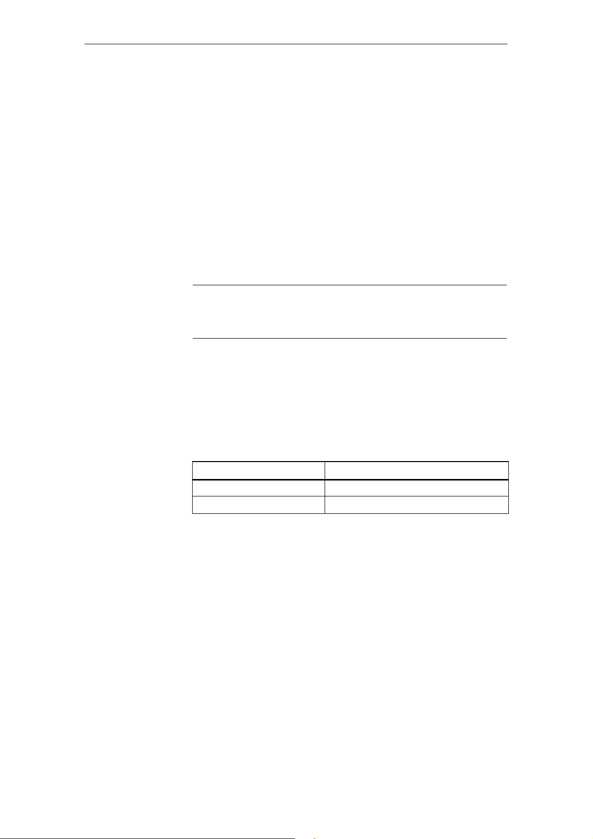
The parameter data for the individual operating modes are combined into
parameter blocks. The required number of parameter blocks depends on the
operating mode which you selected.
The parameters must be transferred at least once to the CM35 after CPU
STOP ® RUN. After the data have been transferred correctly, the red SF
LED goes off and the m odule is ready for operation.
The parameters can be specified again during operation so that the individual
channels can be adjusted to the particular state of the process.
The parameter blocks can be transferred in any sequence. The order has no
effect on their use.
Note
Before a channel can be reparameterized, it must be stopped. The paramet ers
for a channel may not be changed or written while the channel is running.
A parameter block consists of the following.
-- A control word
-- Up to 6 words of data area (parameter data)
Table 4-1 Layout of a parameter block
Word Description
Wor d 1 Control word
Wor ds 2 t o 7 Parameter data
For the allocation and description of the parameter data for the individual
parameter blocks, see the description of the operating mode.
CM35 Counter Module
(4) J31069-D0416-U001-A5-7618
4-3
Page 51
D
ata
Communication with the CM35
Layout of the
control word
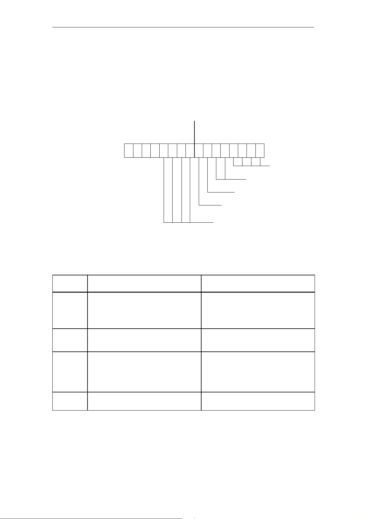
The control word is the first word of each parameter block. The layout of the
control word is shown below.
The bit numbering is specifi ed for the data type ²word.²
-- The low byte of word ²n² has the byte address ²n+1.²
-- The high byte of word ²n² has the byte address ²n.²
Byte n
Start/stop byte
15X14X13X12X11 10 9 8 706 5 4 3 2 1 0
X = Disregard
Byte n+1
Coordination byte
Operating mode
Parameter block number
Consistency bit
Start/stop byte enable
Parameter block subnumber
Table 4--2 shows the permissible allocations of the cont rol word.
Table 4-2 Allocation of the control word for parameterization
Bit
Address
0to3 Identifier
for the set operating mode
4to5 Nu mb er
of the current parameter block
6 Consistency bit
-- Only with parameterization via
direct I/O accesses
-- Not applicable for parameterization
via SFC 55
7 Start/stop byte enable 0: Evaluate parameter data
Description Allocation
0001: Pulse counter operating mode
0010: Period duration measurement
operating mode
0011: Timer operating mode
0100: Positioning operating mode
01: Parameter block 1
10: Parameter block 2
11: Parameter block 3
0: Write parameter block
1: Accept parameter block via CM35
1: Evaluate start/stop byte
4-4
(4) J31069-D0416-U001-A5-7618
CM35 Counter Module
Page 52

D
ata
Table 4-2 Allocation of the control word for parameterization, continued
Communication with the CM35
Bit
Address
8to11 Subnumber for parameter block
-- O n l y f o r ²positioning² mode
-- Not applicable to the operating modes
pulse counter, period duration measurement
and timer
12 to 15 Disregard
Example (S5)
²Timer² mode/parameterization via direct I/O accesses
Write parameter block 2:
To write data assign W#16#0023 to control word
To accept data via CM35 assign W#16#0063 to control word
Data transmission
The parameter blocks for the parameterization of the CM35 can be written in
one of the following ways.
-- Use of data record number 1 with SFC 55 “WR_PARM”
-- Write the analog I/O address area with direct I/O accesses
The data are written with SFC 55 when the CM35 is used with SIMATIC S7.
AllocationDescription
0000: Parameter subblock 0
0001: Parameter subblock 1 (axis 1)
0010: Parameter subblock 2 (axis 2)
0011: Parameter subblock 3 (axis 3)
0100: Parameter subblock 4 (axis 4)
Direct I/O write-- accesses to the data must be used for DP operation with S5
masters or standard DP masters. A consistency bit which must be specified
via the user program is available to ensure the data consistency of a parameter block.
CM35 Counter Module
(4) J31069-D0416-U001-A5-7618
4-5
Page 53
ata
Communication with the CM35
D
4.2.1 Parameterization with SFC 55 (Only SIMATIC S7)
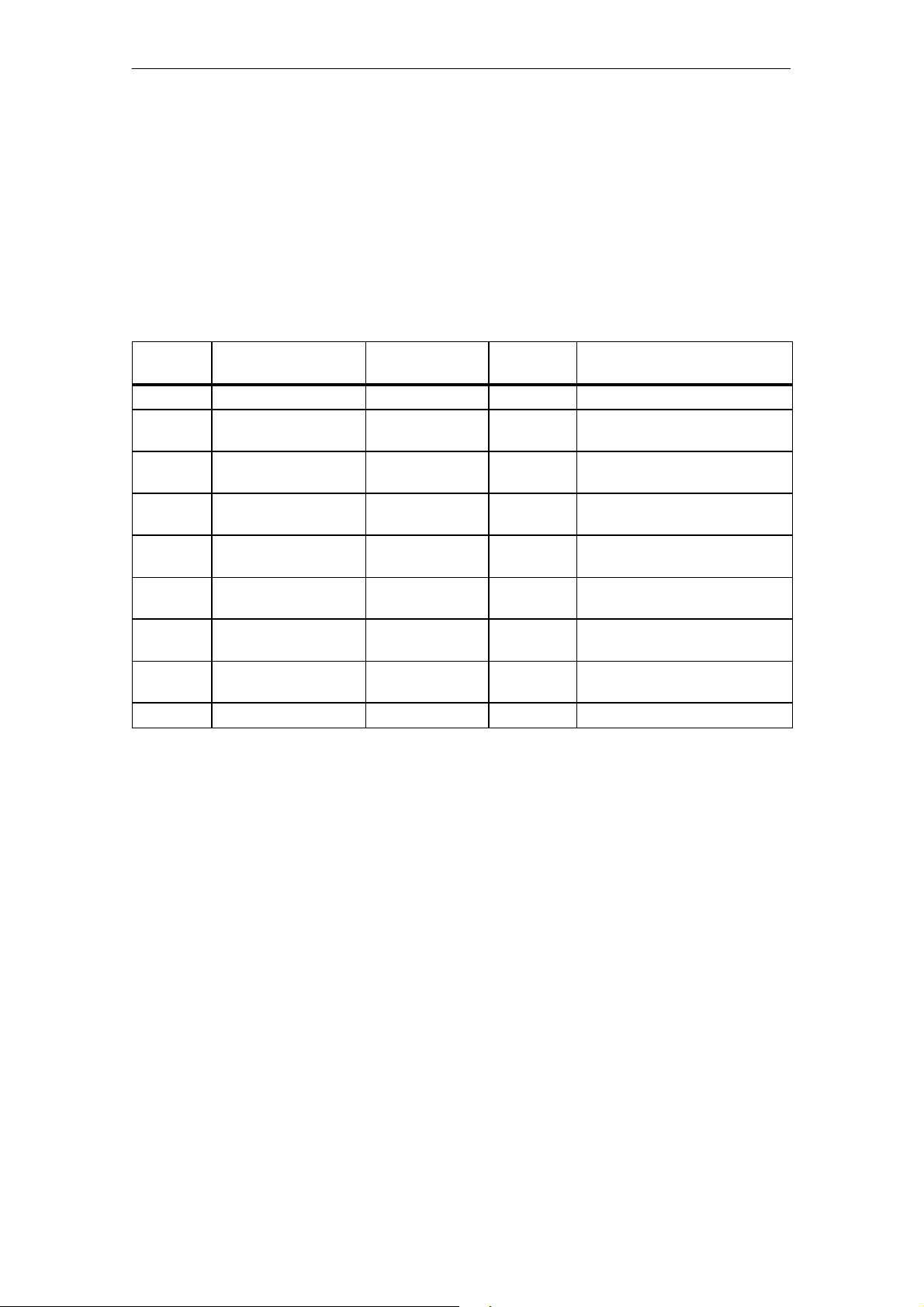
SFC 55 “WR_PARM” can be used to transfer to the module a complet e parameter block (cont rol word and parameterization data, length of 14 bytes) as
data record 1.
Below is an example for the transmission of the 1st parameter block from DB
20 (pulse counting mode). The CM35 has the logical base address 256.
Table 4-3 Sample allocation for a data block (DB 20)
DB
Address
+0.0 Para_Block_1_Data STRUCT
+0.0 Control word WORD W#16#11 Parameter block 1/
+2.0 Cmp_Start_Va-
lue_Chan_1
+4.0 Cmp_Start_Va-
lue_Chan_2
+6.0 Cmp_Start_Va-
lue_Chan_3
+8.0 Cmp_Start_Va-
lue_Chan_4
+10.0 Cmp_Start_Va-
lue_Chan_5
+12.0 Cmp_Start_Va-
lue_Chan_6
=14.0 END_STRUCT
Name Type Initial Value Commentary
pulse counting mode
WORD W#16#00 Comparison value/start value,
channel 1
WORD W#16#00 Comparison value/start value,
channel 2
WORD W#16#00 Comparison value/start value,
channel 3
WORD W#16#00 Comparison value/start value,
channel 4
WORD W#16#00 Comparison value/start value,
channel 5
WORD W#16#00 Comparison value/start value,
channel 6
CALL SFC55
REQ :=true // Request to
write
IOID :=B#16#54 // Area identifie r for
composite mod.
LADDR :=W#16#100 // Logical address = 256
RECNUM :=B#16#1 / / Data record number 1
RECORD :=P#DB20.DBX 0.0 BYTE 14 // Pointer to beginning
of the block
RET_VAL :=#ret_val // Error code
BUSY :=#busy // = 1, writing not
concluded
4-6
(4) J31069-D0416-U001-A5-7618
CM35 Counter Module
Page 54

ata
Communication with the CM35
D
SFC 55 must continue to be called until BUSY is reset.
SFC 55 should not be used in OB100. We recommend setting a flag bit
(startup identifier) in OB100 instead. SFC 55 should then be called based on
this flag bit to parameterize the CM35 after the automation system is turned
on.
If an error occurs while the function is being processed, the error code is indicated in parameter RET_VAL, and BIE is set to ²0.²
For a description of the parameterization of the system functions and the return values, see STEP 7 reference manual /235/.
CM35 Counter Module
(4) J31069-D0416-U001-A5-7618
4-7
Page 55
D
ata
Communication with the CM35
4.2.2 Parameterization via Direct I/O Accesses (Only SIMATIC S5)
Parameterization via direct accesses is only permitted in the ²period duration
measurement² and ²timer² operating modes.
Assignment of the
I/O address area
Use of the consistency bit
The analog I/O address area contains 8 words. The data must be written with
word accesses.
The I/O address area is used for parameterization as shown below.
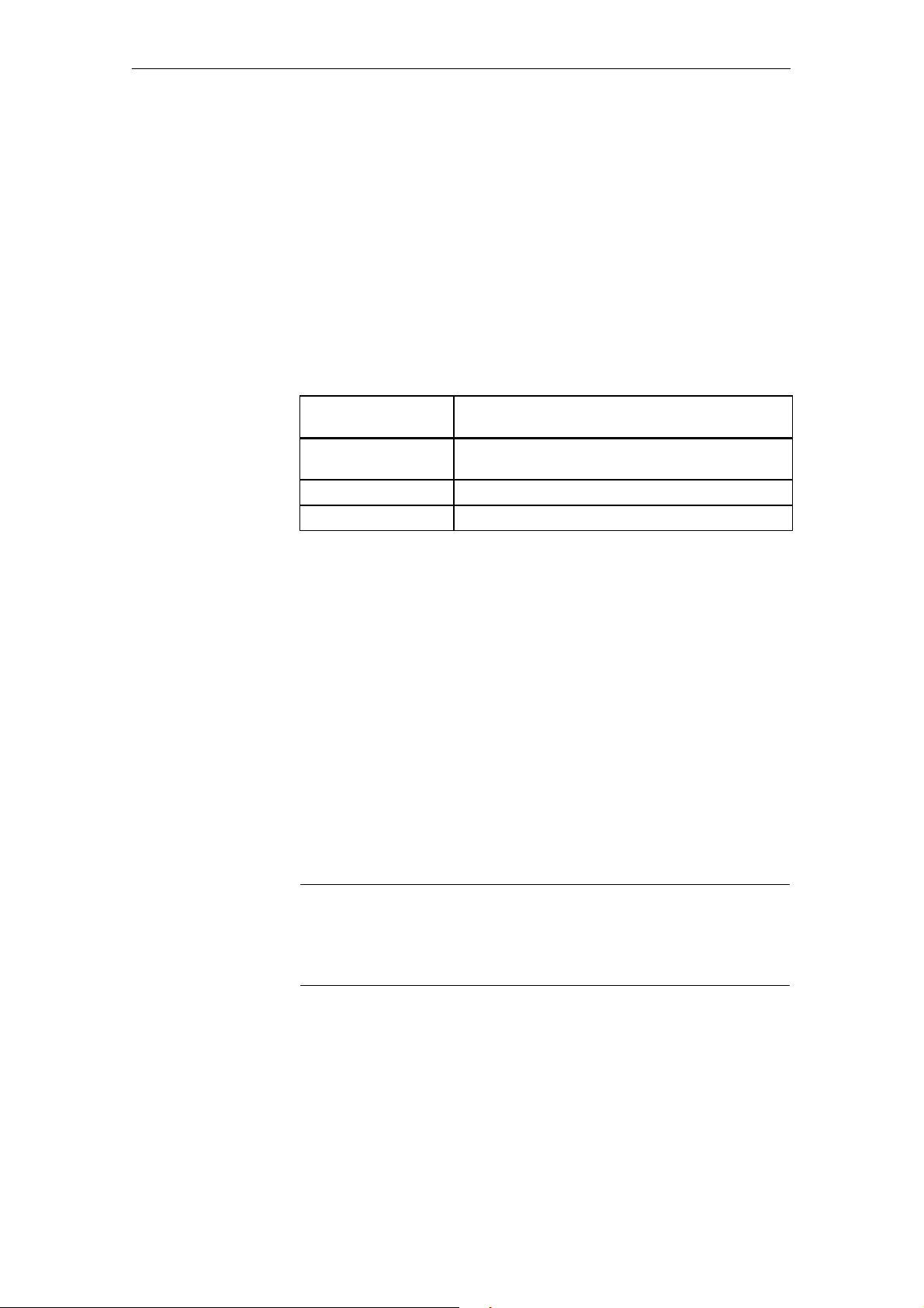
Table 4-4 Assignment of the address area for parameterization via direct I/O
accesses
Offset for the
Module Start Address
+0 DO byte (digital output control)
may not be written during parameterization.
+2 Control word
+4 to +14 Parameterization data
Description
The consistency (”C bit”) in the control word is used with direct--access parameterization to ensure consistency of the written values within one parameter
block.
The CM35 does not evaluate the transferred values of one parameter block as
long as the C bit is not set. These values do not becom e valid until the control word is written with C bit = 1.
Transmission of
parameter blocks
The following sequence must be used to transfer the pafameter blocks.
1. Transfer the control word with C bit = 0.
2. Transfer all required data of the parameter block.
3. Transfer the control word with C bit = 1.
Transfer next parameter block.
Note
The c hannels may not be started or stopped by accesses to the control word
while parameter bl ocks are being transferred. The system must be in a defined state before parameter blocks are transferred.
An example is shown below.
-- ²Timer² operating mode
-- Transmission of the 1st parameter block from DB 20
-- The CM35 has the module start address 128.
4-8
(4) J31069-D0416-U001-A5-7618
CM35 Counter Module
Page 56
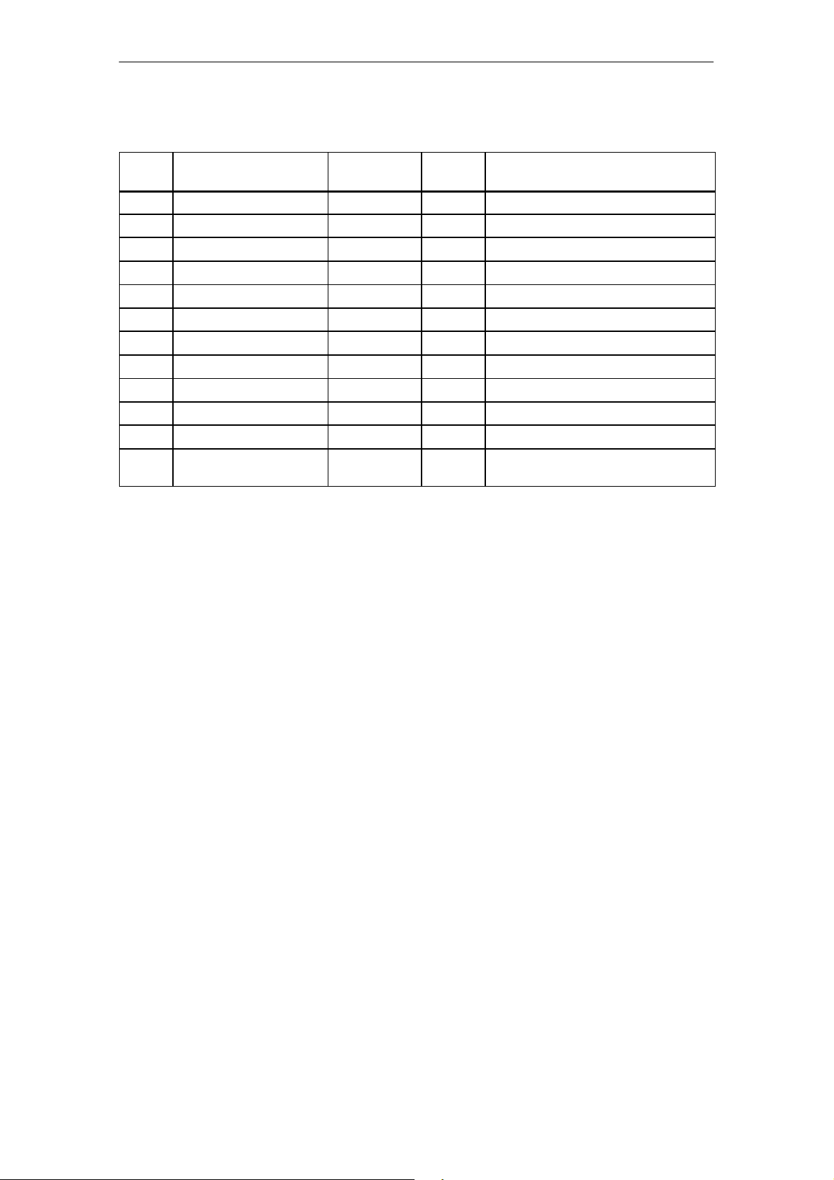
Table 4-5 Sample allocation for a data block (DB 20)
ata
Communication with the CM35
D
DB Ad-
dress
0 Control_word WORD W#16#13 Parameter block 1/²timer² operating mode
2 Timebase_Timer_1 BYTE B#16#01 Time base for timer 1
3 Timebase_Timer_2 BYTE B#16#01 Time base for timer 2
4 Timebase_Timer_3 BYTE B#16#01 Time base for timer 3
5 Timebase_Timer_4 BYTE B#16#01 Time base for timer 4
6 Timebase_Timer_5 BYTE B#16#01 Time base for timer 5
7 Timebase_Timer_6 BYTE B#16#01 Time base for timer 6
8 Timebase_Timer_7 BYTE B#16#01 Time base for timer 7
9 Timebase_Timer_8 BYTE B#16#01 Time base for timer 8
10 Factor_Timer_1 WORD W#16#01 Factor for timer 1
12 Factor_Timer_2 WORD W#16#01 Factor for timer 2
14 Control_word WORD W#16#53 C bit = 1/parameter block 1/
Name Type Initial
Value
²timer² operating mode
Commentary
A DB20 // Open data block.
L DBW0 // Load control word with C bit=0.
T PW 130 // Module start address + 2
L DBW2 // Load time base for timers 1 and 2.
T PW 132 // Module start address + 4
L DBW4 // Load time base for timers 3 and 4.
T PW 134 // Module start address + 6
...
L DBW12 // Load factor for timer 2.
T PW 140 // Module start address + 14
L DBW14 // Load control word with C bit = 1.
T PW 130 // Module start address + 2
Transfer next parameter block.
CM35 Counter Module
(4) J31069-D0416-U001-A5-7618
4-9
Page 57

ata
Communication with the CM35
D
Wait time, OB1/
OB100
When distributed connection to the SIMATIC S5 is used, a wait time must be
adhered to after an S5 CPU STOP/RUN transition, before the module is parameterized via direct I/O accesses.
The wait time depends on the PROFIBUS transmission speed set. It can be
configured in OB 100 or OB 1.
The following standard values apply
.
187.5 kbit/sec ® 500 msec wait time
::
1.5 kbit/sec ® 100 ms wait time
::
12 kbit/sec ® 10 ms wait time
4-10
(4) J31069-D0416-U001-A5-7618
CM35 Counter Module
Page 58
4.3 Programming
ata
Parameterization must be correct before the channels and digital outputs can
be controlled and the actual values can be read.
With both the SIMATIC S7 and the SIMATIC S5, direct I/O accesses are always used. Only word or double--word accesses to even addresses can be
used for I/O accesses.
4.3.1 Controlling the Chann els
The i ndividual channels of the CM35 can be started and stopped by writing
the control word. The control word must be written to address ²module start
address + 2.²
Communication with the CM35
D
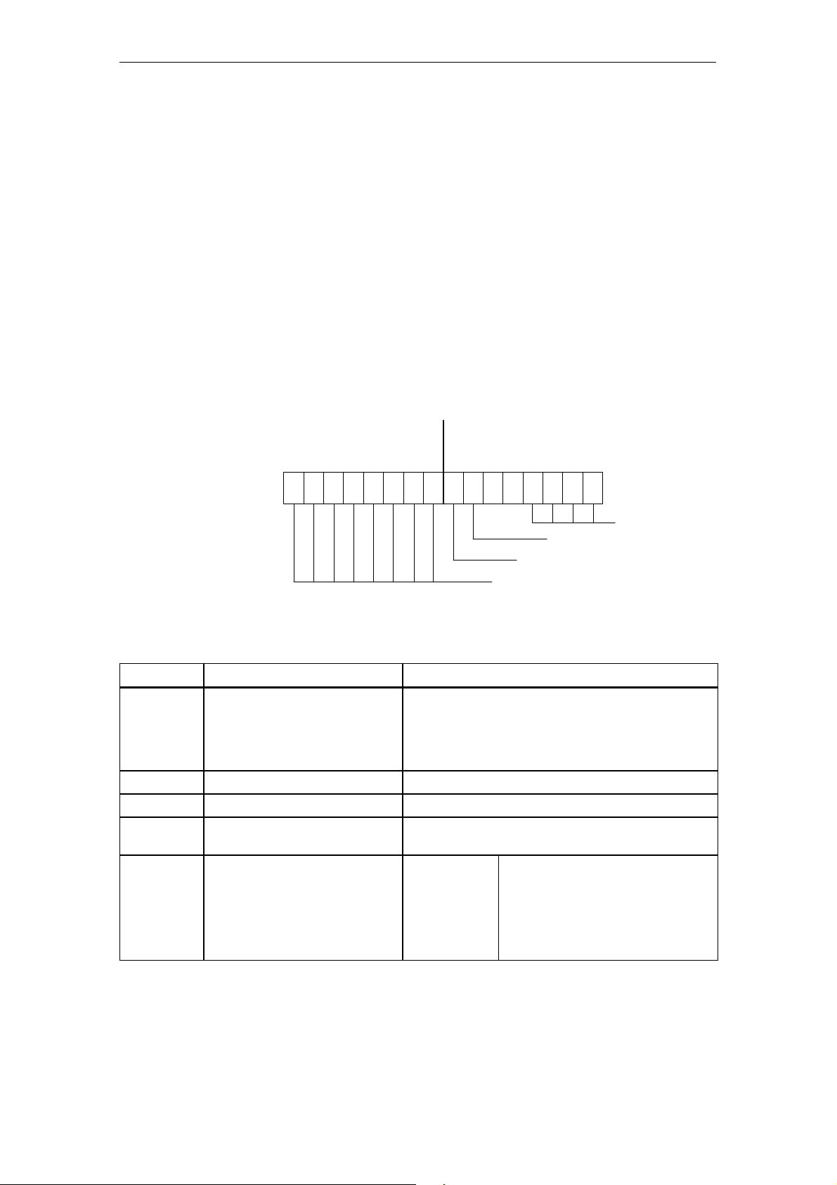
Layout of the
control word
The control word is assigned as shown below to start and stop the channels.
Byte n
Start/stop byte
15 14 13 12 11 10 9 8 716X50403 2 1 0
Byte n+1
Coordination byte
Consistency bit (disregard)
Start/stop byte enable
Start/stop byte
Table 4-6 shows the permissible assignments of the control word.
Table 4-6 Allocation of the control word for controlling the channels
Bit Address
0to3 Identifier
4to5 Always 0 00: Start/stop byte is written.
6 Disregard 0/1: Consistency bit
7 Start/stop byte enable 0: Evaluate parameter data
8to15 Start/stop byte
Oper. mode: Pulse counter
Oper. mode: Positioning
Description Allocation
0001: ²Pulse counter² operating mode
for the operating mode set
Period duration meas.
Timer
0010: ²Period duration measurement²
operating mode
0011: ²Timer² operating mode
0100: ²Positioning² operating mode
1: Evaluate start/stop byte
Bit Address
8to15
9, 8; 11, 10;
13, 12; 15, 14
0: Stop channel
1: Start channel
01: Start axis
10: Stop axis
Oper. mode
CM35 Counter Module
(4) J31069-D0416-U001-A5-7618
4-11
Page 59

ata
Communication with the CM35
D
Example: ²Pulse counter² operating mode
To start all channels, write control word W#16#FF81.
To stop all channels, write control word W#16#0081.
4-12
(4) J31069-D0416-U001-A5-7618
CM35 Counter Module
Page 60
4.3.2 Controlling the Digital Outpu ts
The digital output s of the CM35 can be controlled by the user program, based
on the parameterization selected.
The status of the digital outputs can be specified by writing the DO pattern
(DO byte) to I/O output byte ²module start addre ss + 0.²
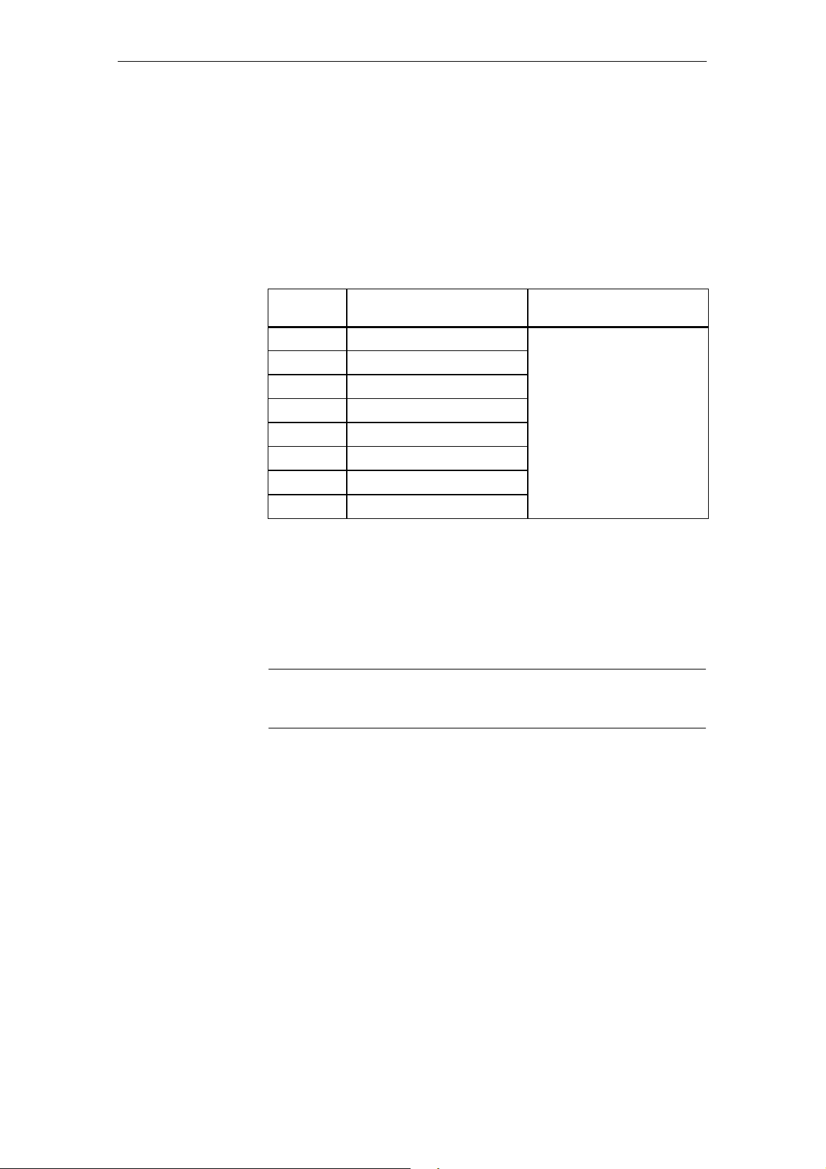
Table 4-7 Allocation of the DO byte for controlling the digital outputs
DataCommunication with the CM35
Bit
Address
0
1
2
3
4
5
6
7
Description Allocation
Digital output 1 0: Digital output off
Digital output 2
Digital output 3
Digital output 4
Digital output 5
Digital output 6
Digital output 7
Digital output 8
1: Digital output on
Example (S7): Set outputs 1 and 5 of the ²pulse counter² operating mode.
- Parameterize DO mode with CPU control.
- The CM35 has the module start address 256.
L 2#0001_0001_0000_0000 // Load DO byte to set outputs 1 and 5
T PQW 256 // Module start address = 256
Note
CM35 Counter Module
(4) J31069-D0416-U001-A5-7618
Remember that only word--accesses to even addresses are permitted.
4-13
Page 61

ata
Communication with the CM35
D
4.3.3 I/O Write Accesses
When I/O write accesses (T PQW) are used, it is essential to remember that
write accesses to the same I/O addresses may overwrite each other before
being transferred to the CM35.
Example, pulse counter:
Start channel 1, then start channel 4 shortly afterwards
L W#16#0181 // Start channel 1
T PQW 258 // Module start address +2
:: :
L W#16#0881 // Start channel 4
T PQW 258 // Module start address +2
If the time between the start of channel 1 and channel 4 is too short, the start
command for channel 1 may be overwritten by the start command for channel 4.
This is particularly apt to happen if you are using distributed connection of
the CM35 with low bus transmission rates. In this case, the 1st start command (channel 1) is overwritten by the 2nd start command (channel 4) before
the 1st start command can be sent to the module via PROFIBUS.
The following measures should be taken to ensure that I/O write accesses do
not compete at the same address.
S The same I/O address may only be write--accessed once during one OB1
cycle.
S When a distributed layout is used, the DP cycle should be at least twice as
fast as the CPU cycle (DP cycle and CPU cycle can be determined with
STEP 7).
4-14
(4) J31069-D0416-U001-A5-7618
CM35 Counter Module
Page 62
4.3.4 Reading the Data
The CM35 supplies the following data, based on the operating mode set.
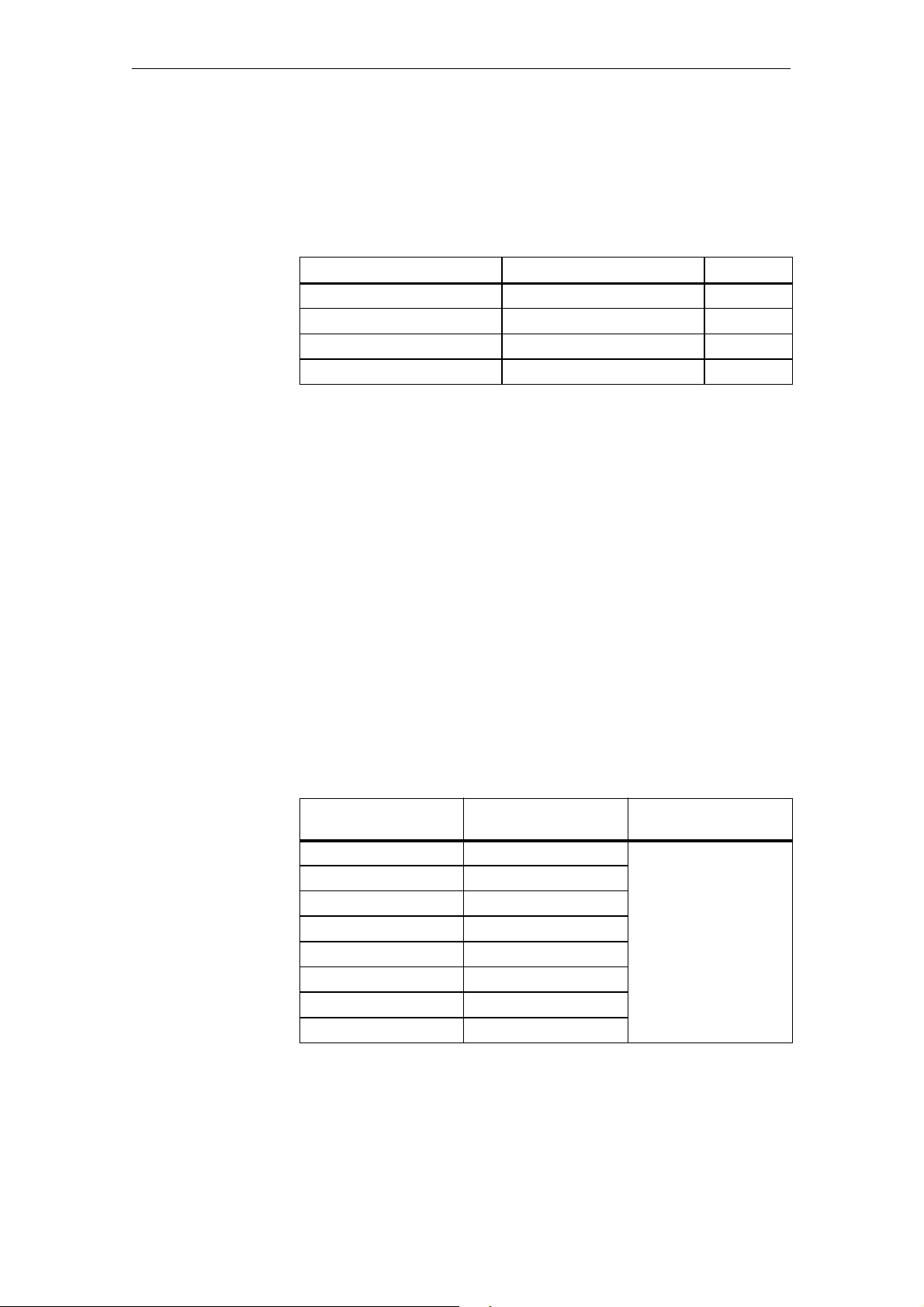
Table 4-8 Data of the CM35
DataCommunication with the CM35
Operating Mode
Pulse counter Current counting value Word
Period duration measurement Measured period duration Wor d
Timer Status of the timer Byte
Positioning Current actual position DWord
Data Data Type
For the allocation and description of the data of the CM35, see the description of the particular operating mode.
Remember the following points which concern the assurance of data consistency based on the programmable controlle r used.
SIMATIC S7 (central or distributed)
Only one single load command (L PIW or L PID) can be used to read the
desired value.
This means that an actual value in double--word format m ust be read with
one double--word access (L PID). Use of t wo word accesses (L PIW) can
cause data inconsistency in this case.
SIMATIC S5 or standard DP master (distributed)
Only word--accesses to even addresses may be used to read--access the de-
sired value.
Table 4-9 shows an example of the address allocation for reading the counting values in ²pulse counter² mode.
Table 4-9 Address allocation of the counting values for the ²pulse counter² operat-
ing mode
Offset to
Module Start Address
+0 Counting value, channel 1 0 to 65535
+2 Counting value, channel 2
+4 Counting value, channel 3
+6 Counting value, channel 4
+8 Counting value, channel 5
+10 Counting value, channel 6
+12 Counting value, channel 7
+14 Counting value, channel 8
Meaning Value Range
CM35 Counter Module
(4) J31069-D0416-U001-A5-7618
4-15
Page 63

ata
Communication with the CM35
D
Example: ²Pulse counter² mode
-- Read counting value of counting channel 4
-- The CM35 has module start address 256.
L PIW 262 // Address = 256 + 6, read counting value,
channel 4
T MW 8 // Save the counting value
4-16
(4) J31069-D0416-U001-A5-7618
CM35 Counter Module
Page 64

D
ata
4.3.5 Evaluating a Hardware Interrupt in OB 40
Depending on the set operating mode and the selected parameterization, you
can specify that a hardware interrupt is to be triggered when certain events
occur. In this case, a hardware interrupt OB (OB 40) must exist on the CPU.
When a hardware interrupt occurs, the user program is inte rrupted, the data
of the module are transferred to the start information of OB 40, and OB 40 is
called. The hardware interrupt is acknowledged when OB 40 is exited.
The following local data are located in the start information of OB 40.
-- OB 40_MDL_ADDR: The base address of the module which trig-
gered the interrupt
-- OB 40_POINT_ADDR: Information on the event which triggered the
interrupt
Variable OB40_POINT_ADDR consists of four bytes. The process
interrupt information of the CM35 is entered in the low word (local data
bytes 10 and 11 of OB 40). For the allocation and description of this interrupt
information, see the description of the particular operating mode .
Communication with the CM35
For a description of OB 40, see STEP 7 reference manual /235/.
CM35 Counter Module
(4) J31069-D0416-U001-A5-7618
4-17
Page 65
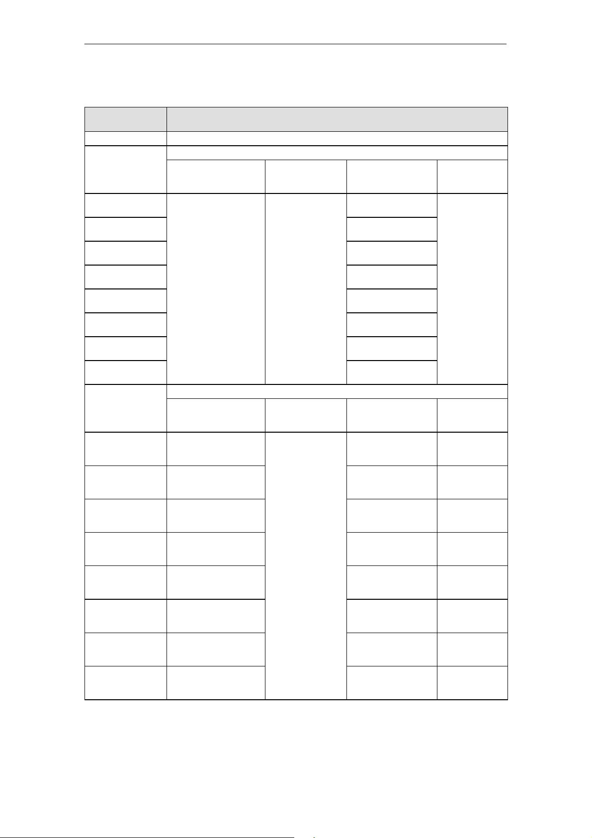
DataCommunication with the CM35
Table 4-10 Hardware interrupts in the various operating modes
Local Data of OB 40 Hardware Interrupts
Local data word 6 Address of the module which triggered the hardware interrupt
Local data byte 10 Operating Mode
Bit 0 Reserved No hardwa re inter-
Bit 1
Bit 2 Timer 3 faulty
Bit 3 Timer 4 faulty
Bit 4 Timer 5 faulty
Bit 5 Timer 6 faulty
Bit 6 Timer 7 faulty
Bit 7 Timer 8 faulty
Local data byte 11 Operating Mode
Bit 0 Counter channel 1 has re -
ached the comparison va-
Bit 1 Counter channel 2 has re -
ached the comparison va-
Bit 2 Counter channel 3 has re -
ached the comparison va-
Bit 3 Counter channel 4 has re -
ached the comparison va-
Bit 4 Counter channel 5 has re -
ached the comparison va-
Bit 5 Counter channel 6 has re -
ached the comparison va-
Bit 6 Counter channel 7 has re -
ached the comparison va-
Bit 7 Counter channel 8 has re -
ached the comparison va-
(The function must have been activated before the interrupts are reported.)
Pulse Counter Period Duration
Pulse Counter Period Duration
lue.
lue.
lue.
lue.
lue.
lue.
lue.
lue.
Measurement
rupts are reported in
this operating mode.
Measurement
No hardware interrupts are reported in
this operating mode.
Timer for
Selective Interrupt
(for Group Interrupt)
Timer 1 faulty
(malfunction of a timer)
Timer 2 faulty
(disregard)
(disregard)
(disregard)
(disregard)
(disregard)
(disregard)
(disregard)
Timer for
Selective Interrupt
(for Group Interrupt)
Time r 1 ha s expired.
(a timer has expired)
Time r 2 ex pired
(disregard)
Time r 3 ex pired
(disregard)
Time r 4 ex pired
(disregard)
Time r 5 ex pired
(disregard)
Time r 6 ex pired
(disregard)
Time r 7 ex pired
(disregard)
Time r 8 ex pired
(disregard)
Positioning
Reserved
Positioning
Axis 1 has reached
setpoint position.
Reserved
Axis 2 has reached
setpoint position.
Reserved
Axis 3 has reached
setpoint position.
Reserved
Axis 4 has reached
setpoint position.
Reserved
4-18
(4) J31069-D0416-U001-A5-7618
CM35 Counter Module
Page 66
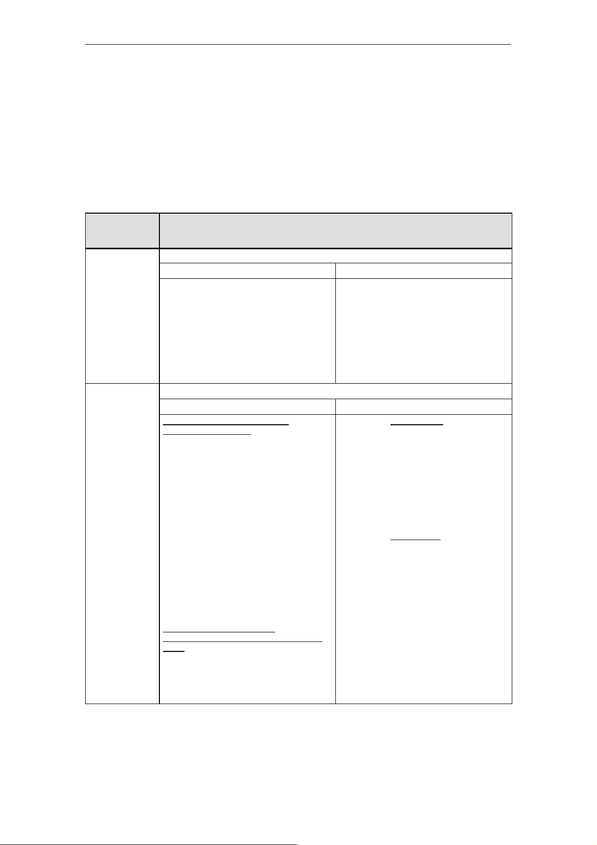
ata
Communication with the CM35
D
4.4 Overview of the Allocation of the Address Area and Sequence of the Evaluation
Allocation of the
address area
Table 4-11 shows a summary of the allocation of the address area for writing
data via direct I/O accesses.
Table 4-11 Allocation of the I/O address area for writing via direct I/O accesses
Offset to
Module Address
(by Word)
+0 Do not write--access during parameterization.
Byte +0 (DO byte) Byte +1 (reserved)
Control digital outputs
(0=off,1=on)
XXXX XXX? Digital output 1
XXXX XX?X Digital output 2
XXXX X?XX Digital output 3
XXXX ?XXX Digital output 4
XXX? XXXX Digital output 5
XX?X XXXX Digital output 6
X?XX XXXX Digital output 7
?XXX XXXX Digital output 8
+2 Control word
Byte +2 (start/stop byte) Byte +3 (coordination byte)
(For SFC55: +0)
Bit allocation when starting/stopping
channels/axes (bit 3.7 = 1)
Operating mode:
Pulse counter, period duration measurement, timer
XXXX XXX? Channel 1: 0 stop, 1 start (*)
XXXX XX?X Channel 2: 0 stop, 1 start (*)
XXXX X?XX Channel 3: 0 stop, 1 start (*)
XXXX ?XXX Channel 4: 0 stop, 1 start (*)
XXX? XXXX Channel 5: 0 stop, 1 start (*)
XX?X XXXX Channel 6: 0 stop, 1 start (*)
X?XX XXXX Channel 7: 0 stop, 1 start (*)
?XXX XXXX Channel 8: 0 stop, 1 start (*)
(*) If the channel was already started, the procedure
is continued when another ²1² occurs.
Operating mode: Positioning
XXXX XX?? Axis 1: 01 start, 10 stop
XXXX ??XX Axis 2: 01 start, 10 stop
XX?? XXXX Axis 3: 01 start, 10 stop
??XX XXXX Axis 4: 01 start, 10 stop
Bit allocation for transmission
parameter blocks (bit 3.7 = 0 and
mode)
XXXX ???? Parameter block subnumber
0000 = Parameter subblock 0
0001 = Parameter subblock 1
:
0100 = Parameter subblock 4
Output Area (16 Bytes)
Always 0
XXXX ???? Operating mode
XX?? XXXX 00: Start/stop
X?XX XXXX: Consistency bit
of
²²²²positioning²²²²
?XXX XXXX: 0: Evaluate parameterization data
0001: Pulse counter
0010: Period duration
measurement
0011: Timer
0100: Positioning
channels/axes
01: Transfer parameter block 1
10: Transfer parameter block 2
11: Transfer parameter block 3
With SIMATIC S7 (SFC 55):
Disregard
With SIMATIC S5:
0: Write parameter block
1: CM35 accepts parameter
block.
Note:
Wait time of 1 msec
between 0 ® 1
1: Evaluate start/stop byte
CM35 Counter Module
(4) J31069-D0416-U001-A5-7618
4-19
Page 67

DataCommunication with the CM35
Table 4-11 Allocation of the I/O address area for writing via direct I/O accesses
Module Address
(by Word)
+4 to +14
(With SFC55:
2to12)
Parameterization data
Pulse counter: Parameter blocks 1 to 3
Period duration measurement: Parameter block 1
Timer: Parameter blocks 1 to 3
Positioning: Parameter block 1 (subnumbers 0 to 4)
Parameterblock2(subnumbers1to4)
Output Area (16 Bytes)Offset to
Note: With parameterization via SFC55, the data to be transferred are set up the same as
output words 2 to 14.
Note
Only word or double--word accesses t o even addresses can be used for I/O
accesses.
4-20
(4) J31069-D0416-U001-A5-7618
CM35 Counter Module
Page 68
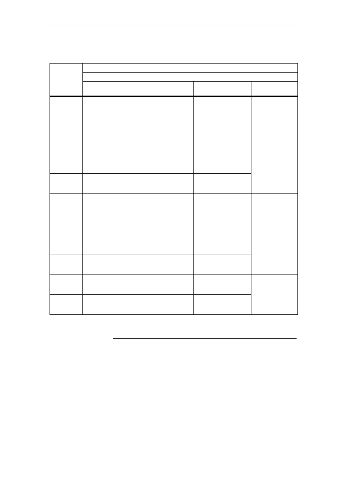
Addr
Address
DataCommunication with the CM35
Table 4-12 Allocation of the I/O address area when reading via direct I/O accesses
Offset to the
Module
ess
(by Word)
+0 Current counting value,
+2 Current counting value,
+4 Current counting value,
+6 Current counting value,
+8 Current counting value,
+10 Current counting value,
+12 Current counting value,
+14 Current counting value,
Pulse Counter Period Duration
channel 1
channel 2
channel 3
channel 4
channel 5
channel 6
channel 7
channel 8
Input Area (16 Bytes)
Operating Mode
Measurement
Measured
period duration average
value, channel 1
Measured
period duration average
value, channel 2
Measured
period duration average
value, channel 3
Measured
period duration average
value, channel 4
Measured
period duration average
value, channel 5
Measured
period duration average
value, channel 6
Measured
period duration average
value, channel 7
Measured
period duration average
value, channel 8
Timer Positioning
Status of timer:
Bit0:Channel1
Bit1:Channel2
Bit2:Channel3
Bit3:Channel4
Bit4:Channel5
Bit5:Channel6
Bit6:Channel7
Bit7:Channel8
0: Timer is active.
1: Timer has expired
and can be started again
after a STOP command.
Reserved
Reserved Current actual
Reserved
Reserved Current actual
Reserved
Reserved Current actual
Reserved
Current actual
position, axis 1
position, axis 2
position, axis 3
position, axis 4
Note
Only word or double--word accesses t o even addresses can be used for I/O
accesses.
CM35 Counter Module
(4) J31069-D0416-U001-A5-7618
4-21
Page 69
D
ata
Communication with the CM35
Order of
evaluation
Start
Change in
DO byte?
No
Change in
coordination
byte?
No
When the CM35 recognizes that new data have been written in its address
area, the DO byte and the coordination byte are evaluated in the following
order.
Evaluate DO
byte and
Yes
Yes
Start/stop
byte
enable = 1?
No
Yes
conclude proc-
essing.
Evaluate
start/stop byte
and conclude
processing.
Conclude processing
Evaluate
Consistency
bit = 1?
No
Conclude processing
Yes
parameter block
and conclude
processing.
Note
Remember that either a change in the DO byte or a change in the coordination byte is evaluated.
4-22
(4) J31069-D0416-U001-A5-7618
CM35 Counter Module
Page 70

Pulse Counter Operating Mode
5
CM35 Counter Module
(4) J31069-D0416-U001-A5-7618
5-1
Page 71
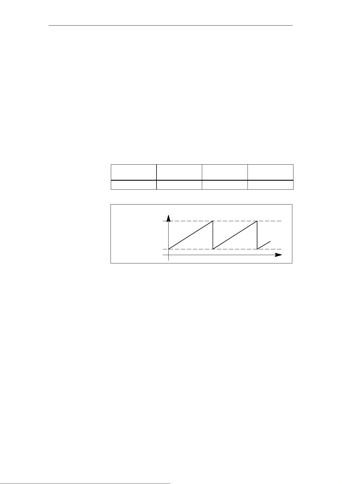
Pu
l
s
r
a
e CounterOpe
tingMode
5.1 Function Description
In this operating mode, the CM35 counts continuously up or down within the
counting range 0 to 65535, when the counter is enabled.
-- When the counting value reaches the upper counting limit when
counting up, and an additional counting pulse occurs, the counting
value j umps to the lower counting limit and continues to count from
there without losing an impulse.
-- When the counting value reaches the lower counting limit when
counting down, and an additional counting pulse occurs, the counting
value jumps to the upper counting limit and continues to count from
there without losing an impulse.
Table 5-1 Counting range
Counting Range
16 bits 0 65535 Max. of 10 kHz
Upper counting
limit
Lower counting
limit
Figure 5-1 Counting up with counter started
Lower Counting
Limit
Counter status
Upper Counting
Limit
Counting
Frequency
5-2
(4) J31069-D0416-U001-A5-7618
CM35 Counter Module
Page 72
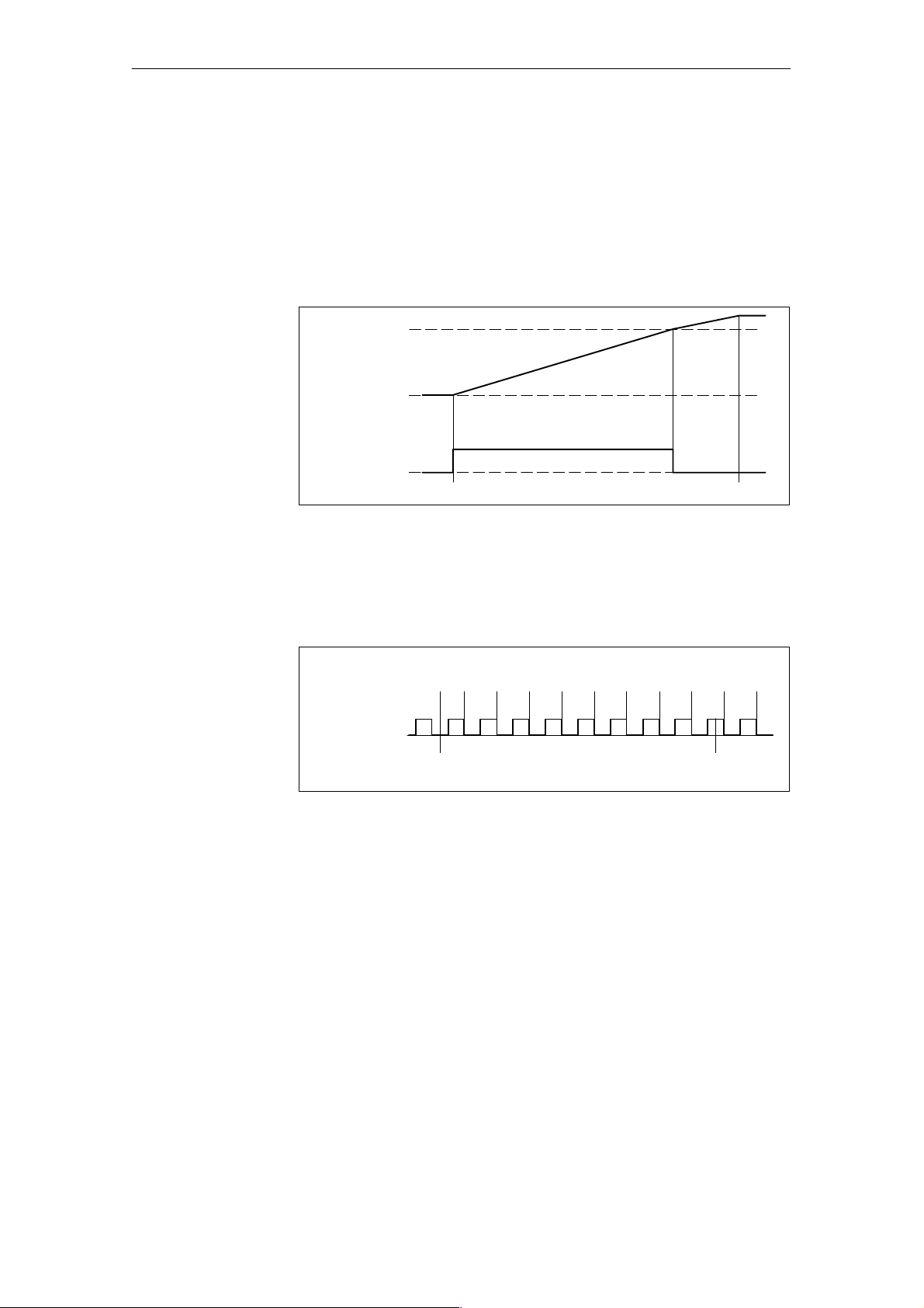
l
s
e CounterOpe
r
a
Pu
tingMode
Starting
or stopping the
counter
Counting edge
The individual count ing channels are started and stopped by the user program. After a counting channel is started, t he encoder pulses are counted.
After a counting channel is stopped, the encoder pulses are no longer acquired.
When a counter is started, the CM35 turns on the related digital output.
When the comparison value is reached, the digital output is switched off and
a hardware interrupt is triggered.
Comparison value
0
Digital
output
Figure 5-2 Switching the digital output, counting direction up
1
0
Counter start
Counter stop
The c ounting value is changed with every falling edge on the related counter
input.
Counting
value
Encoder pulses
Figure 5-3 Evaluation of the encoder pulses, counting direction up
0 1 2 3 4 5 6 7 8 8 8
1
0
Counter start
Counter stop
CM35 Counter Module
(4) J31069-D0416-U001-A5-7618
5-3
Page 73
l
s
e CounterOpe
r
a
Pu
tingMode
5.2 Parameterization
This chapter discusses possible parameterization in ²pulse counter² operating
mode which you can use to adjust the reaction of the count ing channels to
your task.
The parameter data are divided into three parameter blocks. For the structure
of these parameter blocks, see chapter 5.2.2. The number of the parameter
block and the offset in the related structure are specified in the description of
the individual parameter data.
To be able to utilize the ²pulse counter² ope rating mode, you must transfer at
least parameter blocks 1 and 2 to the CM35.
Note
A channel must be stopped before it can be reparameterized.
-- If you want to change channel--specific parameters, this channel must
-- If you want to change parameters affecting more than one channel, all
be stopped.
channels must be stopped.
The new parameterization data take effect when the channel is started again.
For general layout and transmission of the parameter blocks, see chapter 4.2.
5.2.1 Description of the Parameterization Data
Counting direction
When you specify the direction of counting, you determine the direction in
which the encoder pulses are counted.
Counting direction, up: Encoder pulses increment counting value.
Counting direction, down: Encoder pulses decrement counting value.
The parameterized direction of counting applies to all channels.
Table 5-2 Direction of counting
Variable:
Counting
Direction
C_Direction 2 7.0 Bool 0: Counting direction, up
Parameter
Block
Offset Data
Value Range
Type
1: Counting direction,
down
5-4
(4) J31069-D0416-U001-A5-7618
CM35 Counter Module
Page 74
l
s
e CounterOpe
r
a
Pu
tingMode
Comparison value/
start value
When you specify the counting direction, you determine how the comparison
value/start value parameter will be used.
Counting up:
The transferred value is the comparison value.The following happens when a
counter is started.
-- Counting begins with the start value ²0.²
-- The counting value is incremented with each encoder pulse.
When the counting value reaches the specified comparison value, the parameterized reactions are triggered (e.g., reset digi tal output, trigger hardware
interrupt).
Counting down:
The transferred value is the start value. The following happens when a counting procedure is started.
-- The counting value is set to the specified start value.
-- The counting value is decremented with each encoder pulse.
When the counting value reaches the comparison value ²0,² the parameterized reactions are triggered (e.g., reset digital output, trigger hardware interrupt).
The comparison value/ start value can be specified for a specific c hannel.
Table 5-3 Comparison and start value
Variable:
Comparison or Start Value
(Depending on Dir ection of
Counting)
Cmp_Start_Value_Chan_1 1 2.0 Wo rd 0 to 65535
Cmp_Start_Value_Chan_2 1 4.0 Wo rd
Cmp_Start_Value_Chan_3 1 6.0 Wo rd
Cmp_Start_Value_Chan_4 1 8.0 Wo rd
Cmp_Start_Value_Chan_5 1 10.0 Wo rd
Cmp_Start_Value_Chan_6 1 12.0 Wo rd
Cmp_Start_Value_Chan_7 2 2.0 Wo rd
Cmp_Start_Value_Chan_8 2 4.0 Wo rd
Parameter
Block
Offset Data
Type
Value
Range
CM35 Counter Module
(4) J31069-D0416-U001-A5-7618
5-5
Page 75
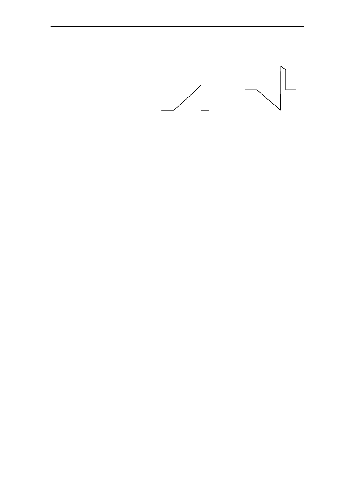
Pu
l
s
r
a
e CounterOpe
tingMode
Counting value
65,535
Upper counting limit
Parameterized
30,000
0
Parameterized
comparison value start value
Start
a) Counting up b) Counting down
Stop Start Stop
Figure 5-4 Use of the comparison value/start value parameter, delete counting value
after stop
5-6
(4) J31069-D0416-U001-A5-7618
CM35 Counter Module
Page 76
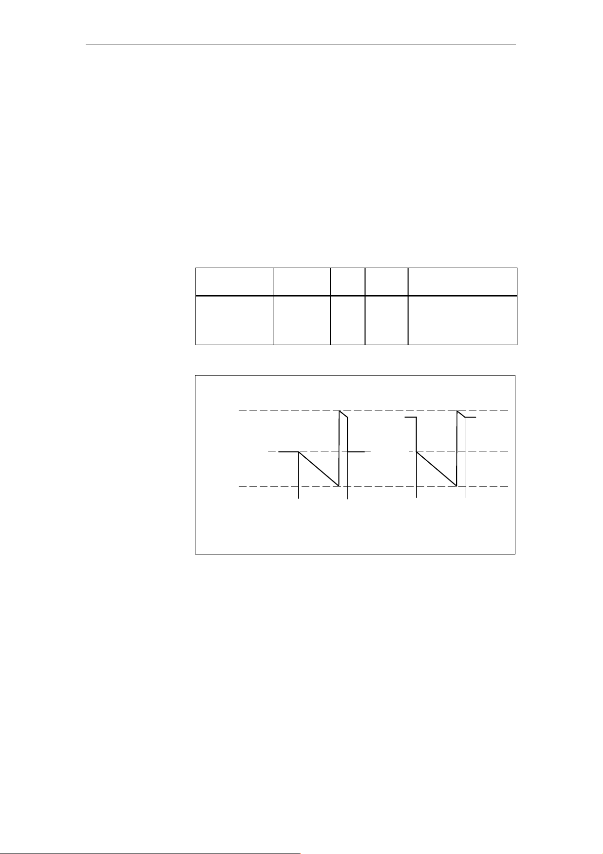
l
s
e CounterOpe
r
a
Pu
tingMode
Counting value
after counter stop
The ²delete counting value² variable can be used to specify which counting
value is to be indicated after stop.
Delete counting value at stop: After the count ing procedure has been
stopped,
the counting value is set to the start value.
Delete counting value at start: After the counting procedure has been
stopped,
the current counting value is retained until
the next start.
Parameterization applies to all channels.
Table 5-4 Delete counting value
Variable
Delete_CountVal 2 7.5 Bool 0: Delete counting value
Parameter
Block
Offset Data
Type
Value Range
at stop
1: Delete counting value
at start
Counting value
65,535
30,000 Start
value
0
Start
a) Delete counting value at stop b) Delete counting value at start
Figure 5-5 Current counting value after a counter has stopped (counting down)
Stop Start Stop
Old
counting
value
Start
value
Counting
value
before
stop
CM35 Counter Module
(4) J31069-D0416-U001-A5-7618
5-7
Page 77
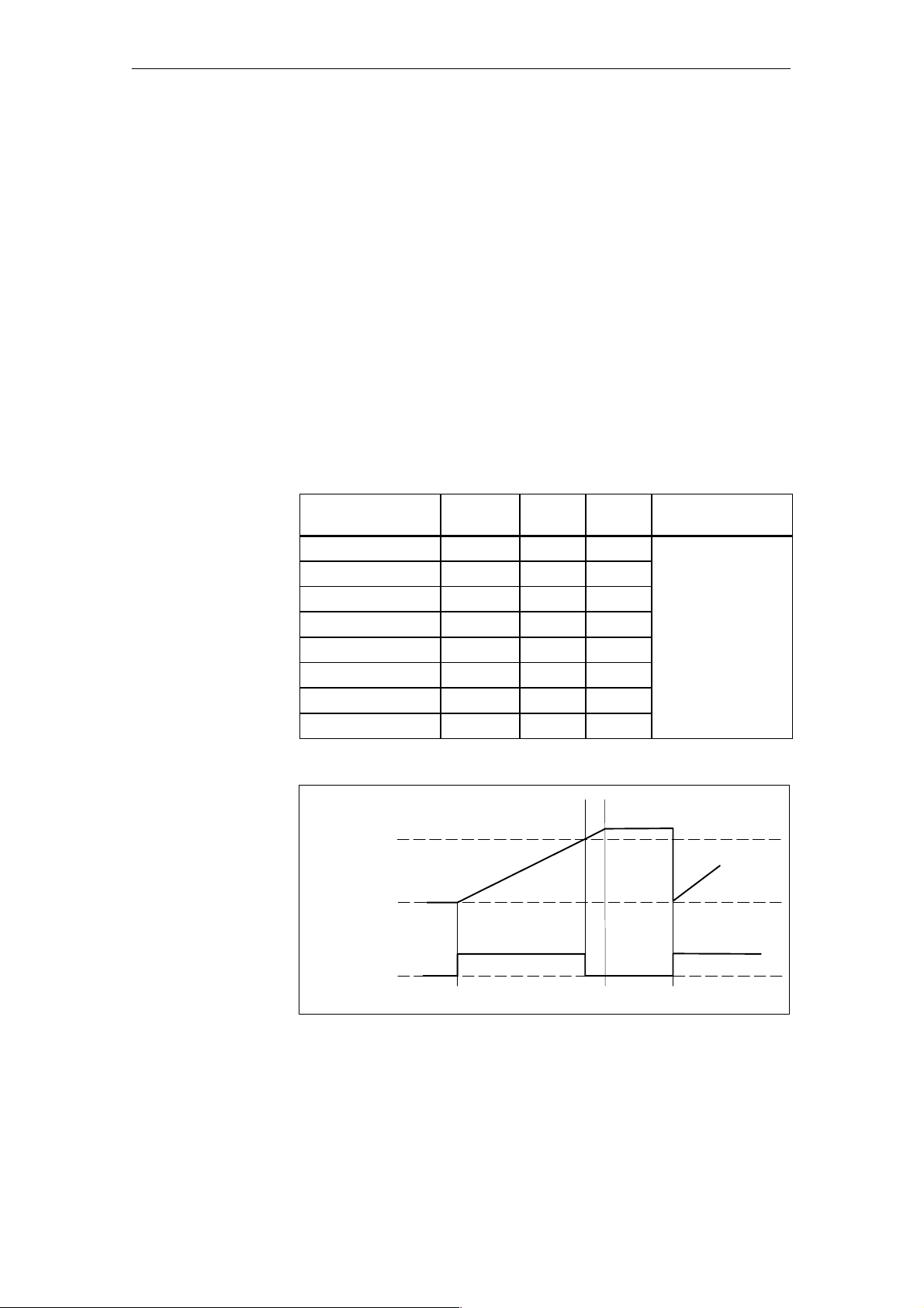
l
s
e CounterOpe
r
a
Pu
tingMode
Switching reaction
of the digital
outputs
You can choose between automatic operation and CPU control to control the
digital outputs.
DO mode
Automatic: When a counter starts, the related output
is switched on.
When the comparison value is reached,
the related output is switched off.
While counting is running, a switched on output can be
reset by the user program.
CPU control: The user program specifies the status of the outputs.
The status is not linked to the counting procedure
(e.g., for adjustment mode).
DO mode can be specified for specific channels.
Table 5-5 DO mode
Variable:
DO_Mode
DO_Mode_Chan_1 2 6.0 Bool 0: Automatic
DO_Mode_Chan_2 2 6.1 Bool
DO_Mode_Chan_3 2 6.2 Bool
DO_Mode_Chan_4 2 6.3 Bool
DO_Mode_Chan_5 2 6.4 Bool
DO_Mode_Chan_6 2 6.5 Bool
DO_Mode_Chan_7 2 6.6 Bool
DO_Mode_Chan_8 2 6.7 Bool
Parameter
Block
Offset Data
Type
Value Range
1: CPU control
5-8
Dribbling
Comparison
value
Start
value
Digital
output
Figure 5-6 Switching of the digital outputs during automatic mode (counting up)
1
0
Stop
(4) J31069-D0416-U001-A5-7618
StartStart
CM35 Counter Module
Page 78
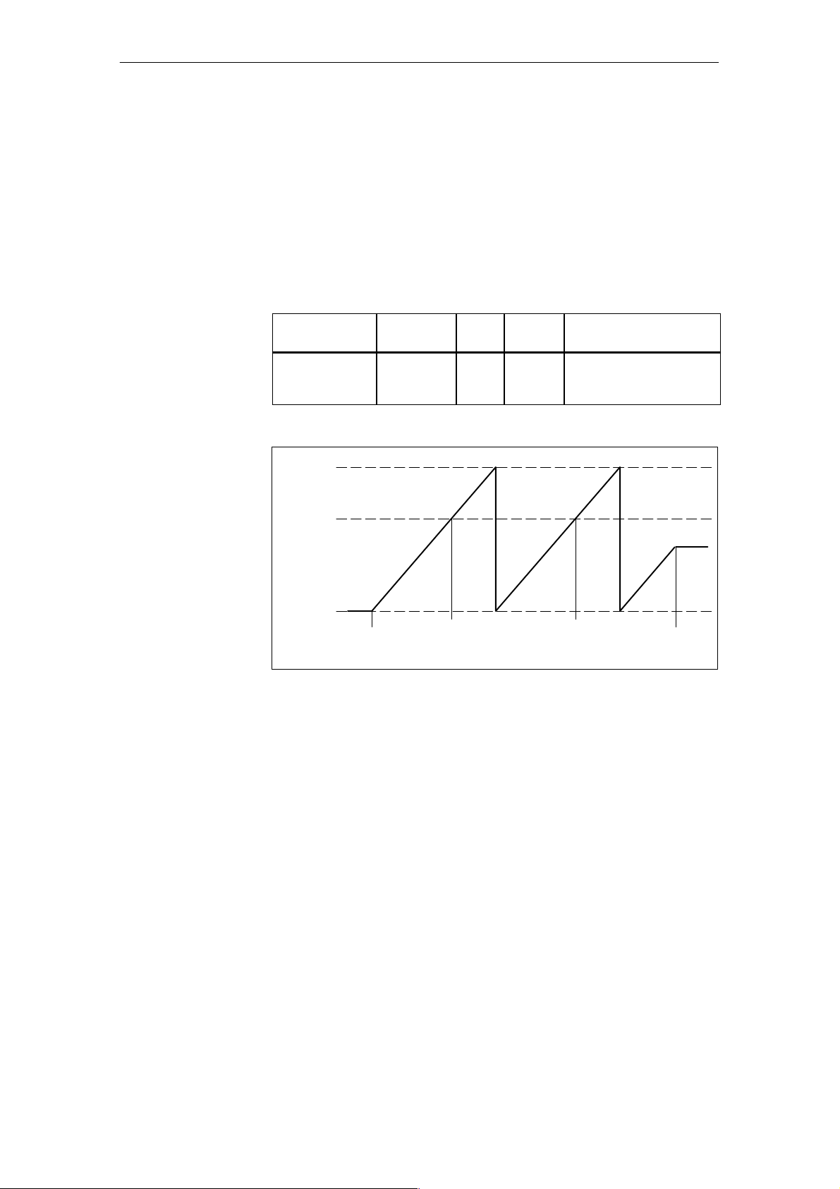
l
s
e CounterOpe
r
a
Pu
tingMode
Hardware
interrupts
You can use the ²interrupt generation² variable to specify whether a hardware
interrupt is to be triggered by the CM35 when the comparison value is
reached. You can use the hardware interrupt OB to evaluate which channel
has reached the comparison value.
After a counter starts, only one hardware interrupt is triggered even when the
comparison value is reached a second time.
Parameterization applies to all channels.
Table 5-6 Interrupt generation
Variable
Interrupt_
Generation
Upper
counting limit
Comparison value
Parameter
Block
2 7.6 Bool 0: No hardware interrupts
Offset Data
Type
Value Range
1: Hardware interrupts
enabled
Start value
Counter
start
Figure 5-7 Hardware interrupt generation (counting up)
Hardware
interrupt
No
hardware
interrupt
Counter
stop
CM35 Counter Module
(4) J31069-D0416-U001-A5-7618
5-9
Page 79
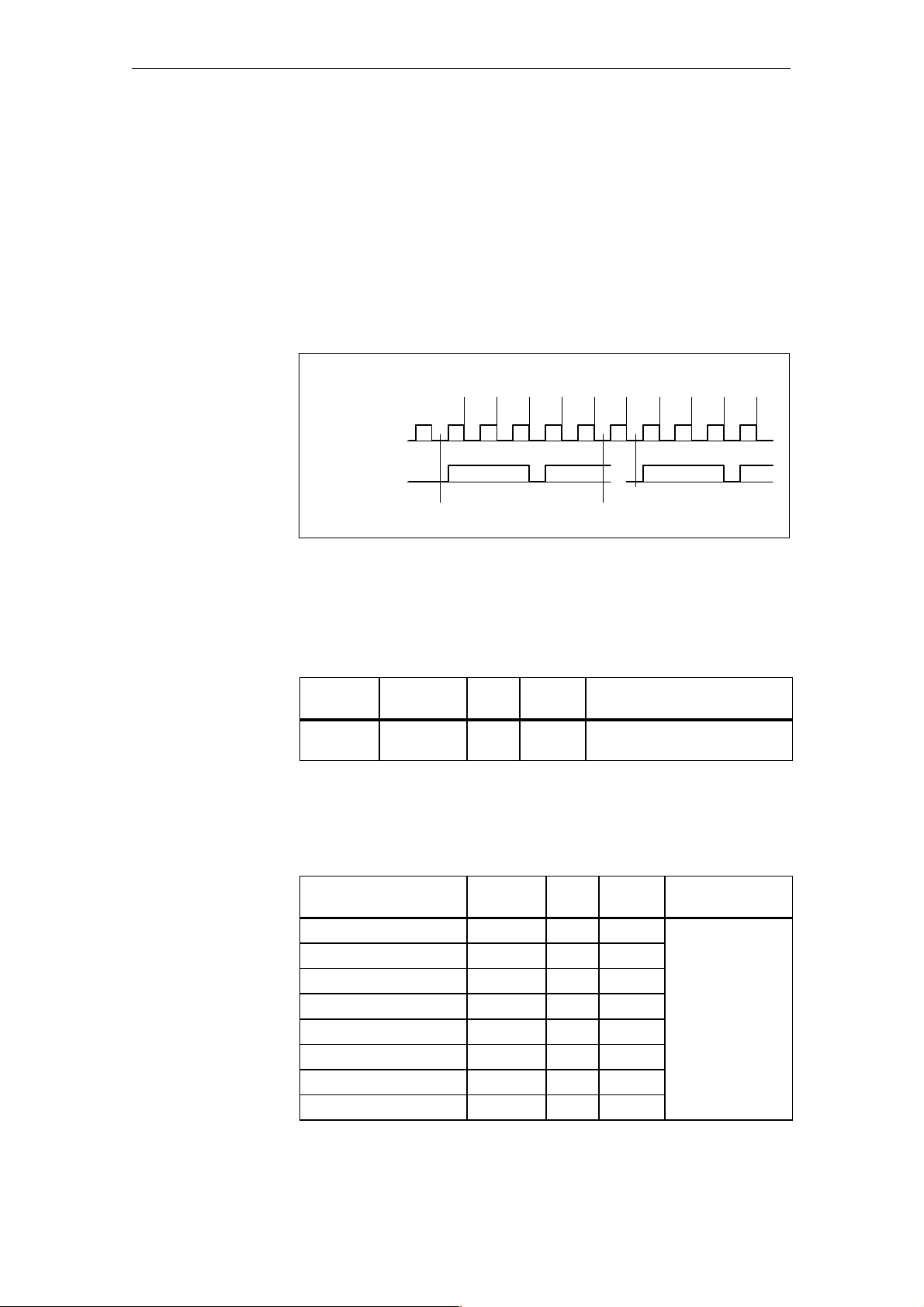
Pu
l
s
r
a
e CounterOpe
tingMode
Scanning rate
You can use the scanning rate factor to specify that the counting value does
not change until the stated number of encoder pulses has occurred.
This increases the counting range of the encoder pulses by a multiple of the
scanning rate factor.
Evaluation of the channel--specific scanning rate factors must be enabled
with the ²scanning rate² group bit.
When a counting procedure starts, the scanning rate factor is always started
again. The remaining pulses are not carried over from the previous counting
procedure.
Counting
value
Encoder pulses
Counting pulses
Figure 5-8 Generation of the counting value with a scanning rate factor of 3
1
0
(counting up)
0 0 1 1 1 1 0 0 1 1
Counter start
Counter start Counter stop
Enabling of a scanning rate factor applies to all channels.
Table 5-7 Scanning rate
Variable
Scanning
Rate
Parameter
Block
2 7.7 Bool 0: Scanning rate not enabled
Offset Data
Type
Value Range
1: Scanning rate enabled
The scanning rate factor can be specified for each channel.
If you specify ²0² or ²1,² the channel does not use the scanning rate.
Table 5-8 Scanning rate factor
Variable:
Scanning Rate Factor
ScanRate_F_Chan_1 2 8.0 Byte 0to255
ScanRate_F_Chan_2 2 9.0 Byte
ScanRate_F_Chan_3 2 10.0 Byte
ScanRate_F_Chan_4 2 11.0 Byte
ScanRate_F_Chan_5 2 12.0 Byte
ScanRate_F_Chan_6 2 13.0 Byte
ScanRate_F_Chan_7 3 2.0 Byte
ScanRate_F_Chan_8 3 3.0 Byte
Parameter
Block
Offset Data
Type
Value Range
5-10
(4) J31069-D0416-U001-A5-7618
CM35 Counter Module
Page 80
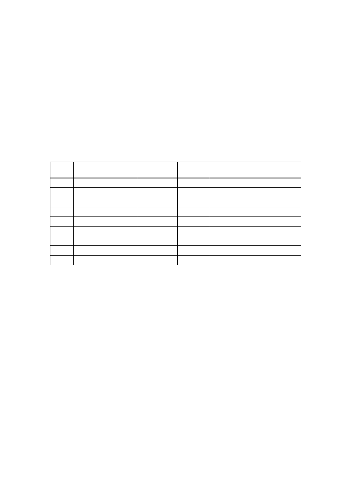
5.2.2 Structure of the Parameter Blocks
l
s
r
a
Tables 5-9, 5-10 and 5-11 show the data structures of the three parameter
blocks as they must be transferred with SFC55 calls to the CM35.
The first word of the parameter blocks contains the control word. The required assignment is entered as the initial value in the structures.
For transmission of the data, see chapter 4.2.
Parameter block 1 contains:
S The comparison or start values for channels 1 to 6
Table 5-9 Parameter block 1
Pu
e CounterOpe
tingMode
Address
+0.0 Control_word WORD W#16#11 Parameter block no. 1/counter mode
+2.0 Cmp_Start_Value_Chan_1 WORD W#16#00 Comparison value/start value, channel 1
+4.0 Cmp_Start_Value_Chan_2 WORD W#16#00 Comparison value/start value, channel 2
+6.0 Cmp_Start_Value_Chan_3 WORD W#16#00 Comparison value/start value, channel 3
+8.0 Cmp_Start_Value_Chan_4 WORD W#16#00 Comparison value/start value, channel 4
+10.0 Cmp_Start_Value_Chan_5 WORD W#16#00 Comparison value/start value, channel 5
+12.0 Cmp_Start_Value_Chan_6 WORD W#16#00 Comparison value/start value, channel 6
=14.0 END_STRUCT
Name Typ e Initial
Value
Para_Block_1_Data STRUCT
Commentary
CM35 Counter Module
(4) J31069-D0416-U001-A5-7618
5-11
Page 81
Pu
l
s
r
a
e CounterOpe
tingMode
Parameter block 2 contains:
S The comparison or start values for channels 7 and 8
S The bit--coded settings
S The scanning rate factors for channels 1 to 6
Table 5-10 Parameter block 2
-- For the switching reaction of the outputs
-- For the direction of counting
-- For the counting value after counter stop
-- For interrupt generation
-- For selection of scanning rate
Address
+0.0 Control_word WORD W#16#21 Parameter block no. 2/counter mode
+2.0 Cmp_Start_Value_Chan_7 WORD W#16#00 Comparison value/start value, channel 7
+4.0 Cmp_Start_Value_Chan_8 WORD W#16#00 Comparison value/start value, channel 8
+6.0 DO_Mode_Chan_1 BOOL FA LSE DO mode: 0 = Automatic
+6.1 DO_Mode_Chan_2 BOOL FA LSE
+6.2 DO_Mode_Chan_3 BOOL FA LSE
+6.3 DO_Mode_Chan_4 BOOL FA LSE
+6.4 DO_Mode_Chan_5 BOOL FA LSE
+6.5 DO_Mode_Chan_6 BOOL FA LSE
+6.6 DO_Mode_Chan_7 BOOL FA LSE
+6.7 DO_Mode_Chan_8 BOOL FA LSE
+7.0 C_Direction BOOL FALS E Counting direction: 0 = Up
+7.1 Enable_Mode BOOL FALSE Enable mode:
+7.2 Reserve_1 BOOL FALS E Reserved
+7.3 Reserve_2 BOOL FALS E
+7.4 Reserve_3 BOOL FALS E
+7.5 Delete_CountVal BOOL TRUE Delete counting value: 0 = At stop
+7.6 Interrupt_Generation BOOL FA LS E Interrupt generation: 0 = none,
+7.7 ScanningRate BOOL FA LS E Scanning rate: 0 = no, 1 = yes
+8.0 ScanRate_F_Chan_1 BYTE B#16#0 Encoder Scanning rate, channel 1
+9.0 ScanRate_F_Chan_2 BYTE B#16#0 Encoder Scanning rate, channel 2
+10.0 ScanRate_F_Chan_3 BYTE B#16#0 Encoder Scanning rate, channel 3
+11.0 ScanRate_F_Chan_4 BYTE B#16#0 Encoder Scanning rate, channel 4
+12.0 ScanRate_F_Chan_5 BYTE B#16#0 Encoder Scanning rate, channel 5
+13.0 ScanRate_F_Chan_6 BYTE B#16#0 Encoder Scanning rate, channel 6
=14.0 END_STRUCT
Name Type Initial V alue Commentary
Para_Block_2_Data STRUCT
1 = CPU control
1 = Down
(only applicable to ²automatic² DO
mode)
0 = Continuous enable
1 = Enable control by DO byte
1=Atstart
1 = active
5-12
(4) J31069-D0416-U001-A5-7618
CM35 Counter Module
Page 82
Parameter block 3 contains:
l
s
r
a
S The scanning rate factors for channels 7 and 8
Table 5-11 Parameter block 3
Pu
e CounterOpe
tingMode
Address
+0.0 Control_word WORD W#16#31 Parameter block no. 3/
+2.0 ScanRate_F_Chan_7 BYTE B#16#0 Encoder scanning rate, channel 7
+3.0 ScanRate_F_Chan_8 BYTE B#16#0 Encoder scanning rate, channel 8
+4.0 Res_4 ARRAY [0..9] B#16#0 In reserve
*1.0 BYTE
=14.0 END_STRUCT
Name Type Initial Value Commentary
Para_Block_3_Data STRUCT
counter mode
CM35 Counter Module
(4) J31069-D0416-U001-A5-7618
5-13
Page 83
l
s
e CounterOpe
r
a
Pu
tingMode
5.3 Starting and Stopping the Counting Channels
After the module has been parameterized, you can start and stop the individual counting channels of the CM35. To do this, write the start/stop block to
the address ²module start address + 2.²
Table 5-12 shows the contents of the start/stop block. The required assignment of the coordination byte is entered as the initial value in the structure.
For a description of the bit assignment of the coordination byte, see chapter
4.3.1.
Write--accesses to the start/stop block must be programmed as word-accesses.
Table 5-12 Start/stop block
Address
+0.0 Start_Stop_Chan_1 BOOL FA LSE 0: Stop channel
+0.1 Start_Stop_Chan_2 BOOL FA LSE
+0.2 Start_Stop_Chan_3 BOOL FA LSE
+0.3 Start_Stop_Chan_4 BOOL FA LSE
+0.4 Start_Stop_Chan_5 BOOL FA LSE
+0.5 Start_Stop_Chan_6 BOOL FA LSE
+0.6 Start_Stop_Chan_7 BOOL FA LSE
+0.7 Start_Stop_Chan_8 BOOL FA LSE
+1.0 CoordinationByte BYTE B#16#81 Start/stop byte enable = 1
=2.0 END_STRUCT
Name Type Initial Value Commentary
Start_Stop_Block STRUCT
1: Start channel
C bit = 0/counter mode
Example: The CM35 has module start address 256.
L W#16#FF81 // Start all channels
T PQW 258 // Module start address + 2
...
...
L W#16#0081 // Stop all channels
T PQW 258 // Module start address + 2
In DO mode ²automatic,² the related output is switched on when a channel
starts. The output is switched off with stop even when the comparison value
has not yet been reached.
5-14
(4) J31069-D0416-U001-A5-7618
CM35 Counter Module
Page 84

5.4 Controlling the Digital Outp uts
l
s
r
a
You can control the digital outputs of the CM35 as shown bel ow, based on
the parameterization of DO mode.
DO mode:
Automatic: Note:
A parameterization bit can be used to specify whether
the DO byte is to control the enable
or whether the enable is continuous.
Enable mode = ²²²²Enable control via DO byte²²²²
The DO byte is used to enable the out put for
control via the counter status.
0: Output disabled
-- The output is not switched on with the start of
counting.
-- A switched on output is forcibly switched off.
1: Output enabled
-- The output is switched on at start of counting.
-- The output is switched off when the comparison
value i s reached or counting is stopped.
Pu
e CounterOpe
tingMode
Enable mode = ²²²²continuous enable²²²²
Control via the counter status is continuously enabled for
the outputs. A switched on output can be forcibly switched
off with the DO byte.
0: A switched on output is forcibly switched
off.
(The forced switch--off only affects the current
counting procedure.)
1: No effect
CPU control: You specify the state of the output with the DO
byte.
0: Switch off output
1: Switch on out put
Write the DO byte to t he address ²module start address + 0.²
Note
Control of the digital outputs must be programmed with a word access.
CM35 Counter Module
(4) J31069-D0416-U001-A5-7618
5-15
Page 85
g
p
D
Omod
²²²²
t
i
²²²²
g
p
Note:
p
y
w
tospecifywhetherenablingistob
e
whethercontinuousenableistobe
l
s
e CounterOpe
r
a
Pu
tingMode
Table 5-13 shows the assignment of the bits of the DO byte to the counting
channels.
Table 5-13 Assignment of the DO byte
Address
+0.0 Digital_Output_Chan_1 BOOL FAL SE DO mode ²²²²CPU control²²²²:
+0.1 Digital_Output_Chan_2 BOOL FAL SE
+0.2 Digital_Output_Chan_3 BOOL FAL SE
+0.3 Digital_Output_Chan_4 BOOL FAL SE
+0.4 Digital_Output_Chan_5 BOOL FAL SE
+0.5 Digital_Output_Chan_6 BOOL FAL SE
+0.6 Digital_Output_Chan_7 BOOL FAL SE
+0.7 Digital_Output_Chan_8 BOOL FAL SE
+1.0 Res_1 BYTE B#16#0 In reserve
=2.0 END_STRUCT
Name Type Initial Value Co mmentary
DO_Block STRUCT
0: Digital output off
1: Digital output on
²²²²
e
automa
0: Digital output off
1: Digital output enabled
Note:
You can use a parameterization bit
to s
ecif
hether enablingis to be
controlled with the DO byte or
hhrnin
used.
nli
Example (S7): Set outputs 1 and 5
- Parameterize DO mode with CPU control
- The CM35 has the module start address 256.
L 2#0001_0001_0000_0000 // Load DO byte to set outputs
1 and 5
²²²²
c
:
T PQW 256 // Module start address = 256
5-16
(4) J31069-D0416-U001-A5-7618
CM35 Counter Module
Page 86
5.5 Hardware Interrupt Evaluation
l
s
r
a
When in ²pulse counter² mode, the CM35 can trigger a hardware interrupt
when a comparison value is reached. If this is used, the CPU must contain a
hardware interrupt OB (OB 40).
The start information of OB 40 contains the following information.
-- The variable OB40_MDL_ADDR contains the base address of the
module which triggered the interrupt.
-- The variable OB40_POINT_ADDR contains information on the event
which caused the interrupt.
The variable OB40_POINT_ADDR consists of four bytes. The hardware interrupt information of the CM35 in ²pulse counter² mode is entered in the
low byte (local byte 11 of OB 40).
By evaluating local byte 11, you can determine which channel triggered the
interrupt. Remember that more than one bit can be set.
Table 5-14 Assignment of the hardware interrupt information (OB 40/local byte 11)
Pu
e CounterOpe
tingMode
Local Byte
11 0 Counter 1 has reached comparison value. 0/1
Bit Meaning Value Range
1 Counter 2 has reached comparison value.
2 Counter 3 has reached comparison value.
3 Counter 4 has reached comparison value.
4 Counter 5 has reached comparison value.
5 Counter 6 has reached comparison value.
6 Counter 7 has reached comparison value.
7 Counter 8 has reached comparison value.
CM35 Counter Module
(4) J31069-D0416-U001-A5-7618
5-17
Page 87
l
s
e CounterOpe
r
a
Pu
tingMode
5.6 Reading the Counting Values
In ²pulse counter² mode, you can read the current counting values from the
CM35.
To ensure data consistency, the read--access must be performed with one load
command (L PIW).
Table 5-15 shows the addresses of the individual channels for reading the
counting value.
Table 5-15 Assignment of the output area for reading the counting values
Offset to the
Module Start Address
+0 Counting value,
+2 Counting value,
+4 Counting value,
+6 Counting value,
+8 Counting value,
+10 Counting value,
+12 Counting value,
+14 Counting value,
Meaning Value Range
channel 1
channel 2
channel 3
channel 4
channel 5
channel 6
channel 7
channel 8
Example: ²Pulse counter² mode
- Read counting value of counting channel 4
- The CM35 has the module start address 256.
0 to 65535
L PIW 262 // Address = 256 + 6, counting value of
channel 4
T MW16 // Save the counting value
5-18
(4) J31069-D0416-U001-A5-7618
CM35 Counter Module
Page 88

Period Duration Measurement Operating Mode
6
CM35 Counter Module
(4) J31069-D0416-U001-A5-7618
6-1
Page 89
Pe
r
r
a
a
sur
r
a
iod Du
tion Me
ement Ope
6.1 Function Description
In this operating mode, the CM35 uses period duration measurement to acquire small frequenci es.
The CM35 measures the e xact time between two falling edges of the counting signal by counting the pulses of an internal precision-quartz reference
frequency. The period duration of the input signal is calculated from the
counting value afte r a period, divided by the reference frequency (in kHz).
Example:
-- Counting value = 100
-- Reference frequency = 100 kHz (standard value)
tingMode
100
= 1 msec ( 1 kHz)
100 kHz
Þ Period duration = 1 msec or frequency = 1 kHz
Measuring range
At a measuring value width of 16 bits and a reference frequency of 100 kHz,
period duration measurements between 655 msec (counting value 65500) and
1 msec (counting value 100) can be performed with a resolution of 1% without switching the range.
Note
The resolution depends on the lower counting value (i.e., the minimum
period duration).
The reference frequency can be adjusted for measurement of longer period
durations. The following table shows the reference frequencies and the resulting measuring range.
Table 6-1 Measuring ranges
Counting
Range
16 bits 100 65500 100 kHz 655 msec to 1 msec
Lower
Counting
Value
Upper
Counting
Value
Reference Frequency Measuring Range
(1.53 Hz to 1 kHz)
50 kHz 1,310 msec to 2 msec
(0.76Hzto500Hz)
25 kHz 2,620 msec to 4 msec
(0.38Hzto250Hz)
6-2
(4) J31069-D0416-U001-A5-7618
CM35 Counter Module
Page 90
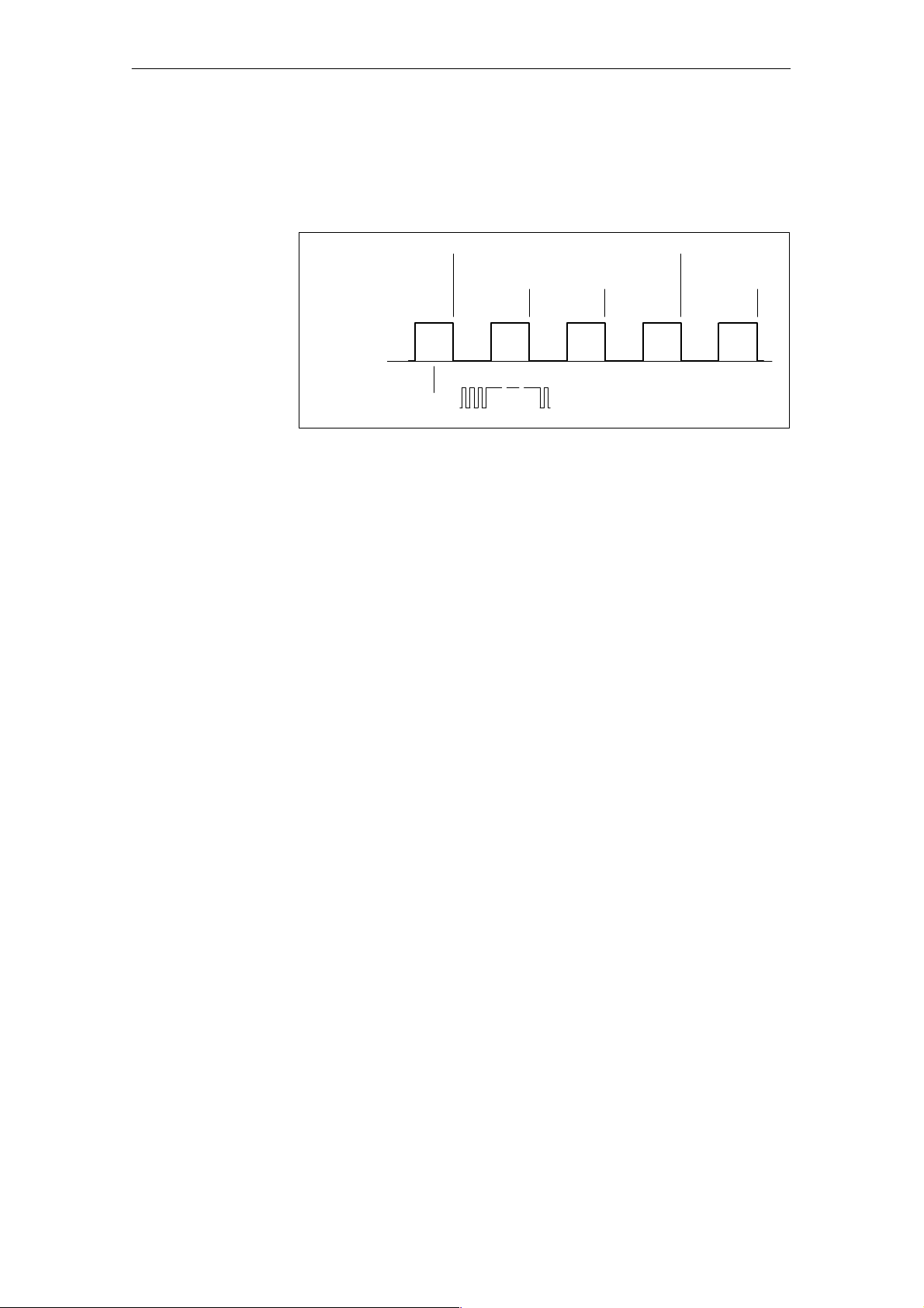
Pe
r
r
a
a
sur
r
a
iod Du
tion Me
ement Ope
tingMode
Period number
Starting and stopping measurement
To eliminate inaccurate measurements, you can also perform the measurement over several periods of the input signal (1 to 40).
An average value can be calculated at the end of the measuring interval.
Measuring interval
1st meas. 2nd meas. 3rd meas. 1st meas.
Input
signal
Reference
signal
Figure 6-1 Principle of period duration measurement over 3 periods of the input signal
Start
The user program starts the individual channels. After a channel is started,
the period duration is acquired based on the parameterization. The channel
must be stopped before a new measurement can be made .
CM35 Counter Module
(4) J31069-D0416-U001-A5-7618
6-3
Page 91

Pe
r
r
a
a
sur
r
a
iod Du
tion Me
ement Ope
6.2 Parameterization
This chapter shows you available parameterizations in ²period duration measurement² mode which you can use to adj ust the reaction of the measuring
channels to your task.
The parameter data are located in a parameter block. For the structure of the
parameter block, see chapter 6.2.2. The description of the individual parameter data include s the number of the paramet er block and the offset in the
structure.
You must transfer parameter block 1 to the CM35 before you can use ²period
duration measurement² mode.
Note
The channel must be stopped before it can be reparameterized.
You must stop the channel before you can change the channel--specific parameters.
tingMode
The new parameters take effect the next time the channel is started.
For a description of the general layout and the transmission of the parameter
block, see chapter 4.2.
6-4
(4) J31069-D0416-U001-A5-7618
CM35 Counter Module
Page 92
Pe
r
r
a
a
sur
r
a
iod Du
6.2.1 Description of the Parameter Data
tion Me
ement Ope
tingMode
Period number
Measuring range
When you specify the number of periods, you determine the number of periods of the input signal during which the measurement is to be performed.
You can specify the number of periods for each channel separately.
Table 6-2 Setting of the number of periods
Variable:
Number of Periods
PeriodNumber_Chan_1 1 2.0 Byte 1to40
PeriodNumber_Chan_2 1 3.0 Byte
PeriodNumber_Chan_3 1 4.0 Byte
PeriodNumber_Chan_4 1 5.0 Byte
PeriodNumber_Chan_5 1 6.0 Byte
PeriodNumber_Chan_6 1 7.0 Byte
PeriodNumber_Chan_7 1 8.0 Byte
PeriodNumber_Chan_8 1 9.0 Byte
Parameter
Block
Offset Data Type Value Range
By selecting the measuring range, you can al so increase the period duration
which is measured.
The parameterized measuring range applies to all channels.
Table 6-3 Setting the reference frequency
Variable:
Measuring Range
F_RefFrequency 1 10.0 Byte 0h: 100 kHz (standard)
Parameter
Block
Offset Data
Type
Value Range
(655 msec to 1 msec)
77h: 50 kHz
(1310 msec
to2msec)
EFh: 25 kHz
(2620 msec
to4msec)
Note
A change in the F_RefFrequency parameter only takes effect with the first
parameter transfer a fter a warm restart (power on).
CM35 Counter Module
(4) J31069-D0416-U001-A5-7618
6-5
Page 93
Period Du
r
a
a
sur
r
a
tion Me
ement Ope
tingMode
6.2.2 Structure of the Parameter Block
Table 6-4 shows the data structure of the parameter block and how to transfer
it to the CM35 using SFC 55 calls or I/O direct accesses.
The first word of the parameter block contains the control word. The structure shows the required assignment as an initial value.
When I/O direct accesses are parameterized (only possible with the
SIMATIC S5), the acceptance structure must be transferred after the data
structure. See table 6-5. The table shows the required assignment of the acceptance structure as an initial value.
Adhere to the specifications in chapter 4.2 which apply to transmission of the
data.
Parameter block 1 contains the following information.
-- The period numbers for channels 1 to 8
-- The factor for reference frequency (measuring range)
Table 6-4 Parameter block 1, data structure
Address
+0.0 Control_word WORD W#16#12 Parameter block no. 1/
+2.0 PeriodNumber_Chan_1 BYTE B#16#1 Period number, channel 1
+3.0 PeriodNumber_Chan_2 BYTE B#16#1 Period number, channel 2
+4.0 PeriodNumber_Chan_3 BYTE B#16#1 Period number, channel 3
+5.0 PeriodNumber_Chan_4 BYTE B#16#1 Period number, channel 4
+6.0 PeriodNumber_Chan_5 BYTE B#16#1 Period number, channel 5
+7.0 PeriodNumber_Chan_6 BYTE B#16#1 Period number, channel 6
+8.0 PeriodNumber_Chan_7 BYTE B#16#1 Period number, channel 7
+9.0 PeriodNumber_Chan_8 BYTE B#16#1 Period number, channel 8
+10.0 F_RefFrequency BYTE B#16#0 Factor for reference frequency
+ 12.0 Res_12 WORD W#16#0 In reserve
= 14.0 END_STRUCT
Name Type Initial Value Commentary
Para_Block_1_Data STRUCT
²period duration measurement² mode
Table 6-5 Parameter block 1, acceptance structure (only with SIMATIC S5)
Address
Para_Block_1_Accept STRUCT
+0.0 Control_word WORD W#16#52 Consistency bit = 1/
=2.0 END_STRUCT
6-6
Name Type Initial Value Commentary
parameter block no. 1/
²period duration measurement² mode
(4) J31069-D0416-U001-A5-7618
CM35 Counter Module
Page 94
Pe
r
r
a
a
sur
r
a
iod Du
tion Me
6.3 Starting and Stopping the Measuring Channels
After parameterizing the module, you can start and stop the indivi dual measuring channels of the CM35. To do this, write the start/stop block to address
²module start address + 2.²
Table 6-6 shows the contents of the start/stop block. The required assignment of the coordination byte is entered as an initial value in the structure.
For a description of the bit assignment of the coordination byte, see chapter
4.3.1.
Table 6-6 Start/stop block
ement Ope
tingMode
Address
+0.0 Start_Stop_Chan_1 BOOL FA LSE 0: Stop channel
+0.1 Start_Stop_Chan_2 BOOL FA LSE
+0.2 Start_Stop_Chan_3 BOOL FA LSE
+0.3 Start_Stop_Chan_4 BOOL FA LSE
+0.4 Start_Stop_Chan_5 BOOL FA LSE
+0.5 Start_Stop_Chan_6 BOOL FA LSE
+0.6 Start_Stop_Chan_7 BOOL FA LSE
+0.7 Start_Stop_Chan_8 BOOL FA LSE
+1.0 CoordinationByte BYTE B#16#82 Start/stop byte enable = 1
=2.0 END_STRUCT
Name Type Initial Value Commentary
Start_Stop_Block STRUCT
1: Start channel
Cbit=0
²Period duration measurement²
mode
Example: The CM35 has the module start address 256.
L W#16#0382 // Start channels 1 and 2
T PQW 258 // Module start address + 2
to
...
L W#16#0182 // Stop channel 2/
channel 1 still active
T PQW 258 // Module start address + 2
CM35 Counter Module
(4) J31069-D0416-U001-A5-7618
6-7
Page 95
1:D
igital
Pe
r
r
a
a
sur
r
a
iod Du
tion Me
ement Ope
tingMode
6.4 Controlling the Digital Outp uts
Since no function is assigned to the digital outputs in ²period duration measurement² mode, they c an be used as desired.
The DO byte is used to specify the state of the digital outputs.
0: Switch off output
1: Switch on output
The m odule firmware switches off the outputs during the transition of the
CPU to the STOP state (BASF/OD signal)
Write the DO byte to address ²module start address
+0.²
Table 6-7 shows the assignment of the bits of the DO byte to the measuring
channels.
Note
Control of the digital outputs must be programmed with a word access.
.
Table 6-7 Assignment of the DO byte
Address
+0.0 Digital_Output_Chan_1 BOOL FAL SE
+0.1 Digital_Output_Chan_2 BOOL FAL SE
+0.2 Digital_Output_Chan_3 BOOL FAL SE
+0.3 Digital_Output_Chan_4 BOOL FAL SE
+0.4 Digital_Output_Chan_5 BOOL FAL SE
+0.5 Digital_Output_Chan_6 BOOL FAL SE
+0.6 Digital_Output_Chan_7 BOOL FAL SE
+0.7 Digital_Output_Chan_8 BOOL FAL SE
+1.0 Res_1 BYTE B#16#0 In reserve
=2.0 END_STRUCT
Name Type Initial Value Co mmentary
DO_Block STRUCT
0: Digital output off
Example (S7): Set outputs 1, 3 and 5
-- The CM35 has the module start addre ss 256.
L 2#0001_0101_0000_0000 // Load DO byte to set outputs
1, 3 and 5
output on
T PQW 256 // Module start address = 256
6-8
(4) J31069-D0416-U001-A5-7618
CM35 Counter Module
Page 96

6.5 Hardware Interrupt Evaluation
r
a
a
sur
r
a
Hardware interrupts are not generated in ²period duration measurement²
.
mode
Period Du
tion Me
ement Ope
tingMode
CM35 Counter Module
(4) J31069-D0416-U001-A5-7618
6-9
Page 97
Pe
r
r
a
a
sur
r
a
iod Du
tion Me
ement Ope
tingMode
6.6 Reading the Measured Values
You can read the current measuring values of the CM35 in ²period duration
measurement² mode.
To ensure data consistency, the read access must be performed with one load
command (L PIW).
When an overflow occurs, the hex value FFFDH (65533) is transferred (frequency below the minimum frequency, encoder interrupted, and so on).
Measuring channels which have not yet been started are transferred with the
value 0000H regardless of whether or not pulses are present on the input.
Table 6-8 shows the addresses of the individual channels for reading the measured value.
Table 6-8 Assignment of the output area for reading the measured values
Offset to the
Module Start Address
+0 Period duration average value, chan. 1 0 to 65532
+2 Period duration average value, chan. 2
+4 Period duration average value, chan. 3
+6 Period duration average value, chan. 4
+8 Period duration average value, chan. 5
+10 Period duration average value, chan. 6
+12 Period duration average value, chan. 7
+14 Period duration average value, chan. 8
Meaning Value Range
Example: ²Period duration measurement² mode
-- Read the measured value of channel 2
-- The CM35 has the module start addre ss 256.
L PIW 258 // Address = 256 + 2, measured value
channel 2
T MW16 // Save the counting value
6-10
(4) J31069-D0416-U001-A5-7618
CM35 Counter Module
Page 98

Timer Operating Mode
7
CM35 Counter Module
(4) J31069-D0416-U001-A5-7618
7-1
Page 99

Time
rOper
a
tingMode
7.1 Function Description
Timer mode can be used to implement precisely defined switch--on times for
the 8 digital outputs of the counter module.
Switch--on times
Start and stop
timers
Controlling the
outputs
Times from 10 milliseconds to 278 minutes can be specified seperately for
the switch--on times.
The timers are started by the user program, thus setting the related digital
outputs.
If no parameter values for time base and factor are available when a timer is
started, these values are processed with 1 as the default value.
The related digital output is switched off after the parameterized time
expires.
A started timer can be terminated by transferring the control word with a ²0²
for the applicable channel in the start/stop byte. This resets the digital output
and the internal counter.
The end of the switch--on time is indicated by a hardware interrupt. This can
be acquired by the user program to trigger additional processing (e.g., to
position the next container in proportioning systems/filling systems).
A timer must be stopped before the user program can execute a new start.
This can be done after the ²timer expired² hardware interrupt or after a time
calculate d by t he user program which is with certainty longer than the run
time of the timer.
The digital outputs of the timer can also be controlled by writing the DO byte
(e.g., for continuous switch--on during washing procedures). The user program must ensure that the timer channels cannot be manipulated
(see chapter 7.4).
Monitoring the
outputs
7-2
The module can monitor the switching status of its outputs. To do this, the
digital outputs must be wired to the digital inputs. The firmware cyclically
compares the status of the digital outputs with the status of the digital inputs
and generates a hardware interrupt when required by the parameterization
(e.g., timer failure). The interrupt can be output as a group interrupt or as a
selective interrupt (i.e., channel--specific).
(4) J31069-D0416-U001-A5-7618
CM35 Counter Module
Page 100

7.2 Parameterization
rOper
a
This chapter describes possible parameterization in timer mode which you
can use to adapt timer reactions to your task.
The parameter data are divided into three parameter blocks. For the structure
of the parameter blocks, see chapter 7.2.2. The descriptions of the individual
parameter data include the number of the parameter block and the offset in
the related structure.
To be able to utilize ²timer² operating mode, you must transfer parameter
blocks 1, 2 and 3 to the CM35.
Note
The timer must be stopped before it can be reparameterized.
-- When you want to change timer--specific parameters, you must stop
-- When you want to change timer--overlapping parameters, you must
the applicable timer.
stop all timers.
Time
tingMode
The new parameter data take effect when the timer is started again.
For a description of the general layout and transfer of the parameter blocks,
see chapter 4.2.
CM35 Counter Module
(4) J31069-D0416-U001-A5-7618
7-3
 Loading...