

Page 1

SIMATIC
Industrial Ethernet - CloudConnect
SIMATIC CC712
Operating Instructions
05/2019
C79000
Preface
Application and functions
1
LEDs, Connectors, Buttons,
CLP
2
Installation, wiring,
commissioning
3
Configuration
4
Diagnostics and
maintenance
5
Technical specifications
6
Approvals
7
Dimension drawings
8
Accessories
A
SIMATIC CC712
-G8976-C503-01
Page 2

Siemens AG
Digital Industries
Postfach 48 48
90026 NÜRNBERG
GERMANY
C79000-G8976-C503-01
Ⓟ
Copyright © Siemens AG 2019.
All rights reserved
DANGER
indicates that death or severe personal injury will result if proper precautions are not taken.
WARNING
indicates that death or severe personal injury may result if proper precautions are not taken.
CAUTION
indicates that minor personal injury can result if proper precautions are not taken.
NOTICE
indicates that property damage can result if proper precautions are not taken.
WARNING
Siemens products may only be used for the applications described in the catalog and in the relevant technical
ambient conditions must be complied with. The information in the relevant documentation must be observed.
Legal information
Warning notice system
This manual contains notices you have to observe in order to ensure your personal safety, as well as to prevent
damage to property. The notices referring to your personal safety are highlighted in the manual by a safety alert
symbol, notices referring only to property damage have no safety alert symbol. These notices shown below are
graded according to the degree of danger.
If more than one degree of danger is present, the warning notice representing the highest degree of danger will
be used. A notice warning of injury to persons with a safety alert symbol may also include a warning relating to
property damage.
Qualified Personnel
The product/system described in this documentation may be operated only by personnel qualified for the specific
task in accordance with the relevant documentation, in particular its warning notices and safety instructions.
Qualified personnel are those who, based on their training and experience, are capable of identifying risks and
avoiding potential hazards when working with these products/systems.
Proper use of Siemens products
Note the following:
documentation. If products and components from other manufacturers are used, these must be recommended
or approved by Siemens. Proper transport, storage, installation, assembly, commissioning, operation and
maintenance are required to ensure that the products operate safely and without any problems. The permissible
Trademarks
All names identified by ® are registered trademarks of Siemens AG. The remaining trademarks in this publication
may be trademarks whose use by third parties for their own purposes could violate the rights of the owner.
Disclaimer of Liability
We have reviewed the contents of this publication to ensure consistency with the hardware and software
described. Since variance cannot be precluded entirely, we cannot guarantee full consistency. However, the
information in this publication is reviewed regularly and any necessary corrections are included in subsequent
editions.
05/2019 Subject to change
Page 3
Preface
Validity of the document
Product name
Article number
Functions
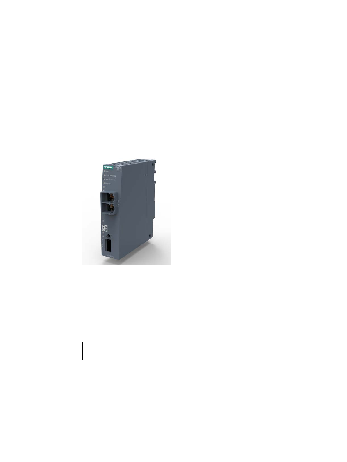
SIMATIC CC712
Connection of 1 process station
This document contains information on the following product:
● SIMATIC CC712
Article number: 6GK1411-1AC00
Hardware product version 1
Firmware version V1.1
Gateway for connection of a SIMATIC S7 or Modbus s
server for SIMATIC S7 data
tation to a cloud system, OPC UA
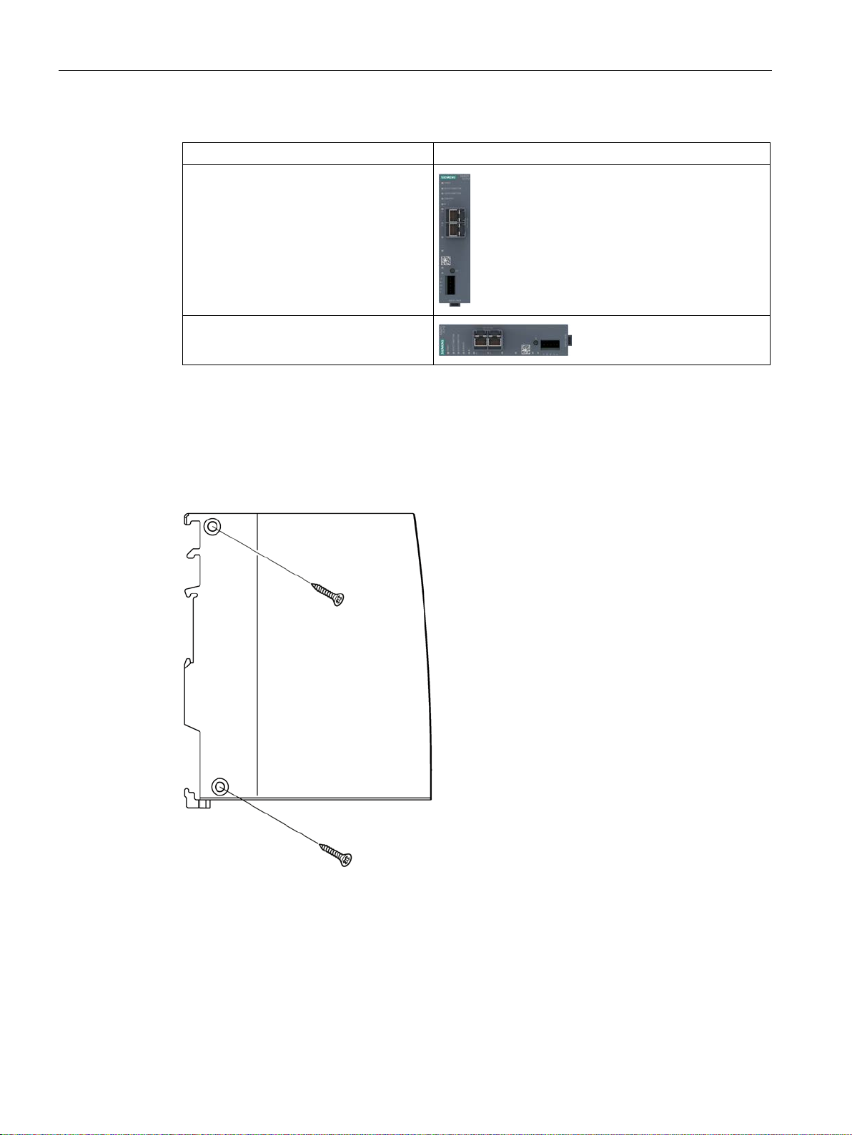
Figure 1 SIMATIC CC712
The MAC address of the device is located below the socket for the power supply. You will
find the article number on the device front.
You will find the hardware product version on the right side of the device as placeholder "X".
"X 2 3 4", for example, indicates hardware product version 1.
The gateway is available in the following versions:
Table 1 Article numbers
Purpose of the manual
This manual describes the properties of the module and shows application examples. It
supports you when installing, connecting up and commissioning the module.
The required configuration steps are described. You will also find instructions for operation
and information about the diagnostics options.
SIMATIC CC712
Operating Instructions, 05/2019, C79000-G8976-C503-01
6GK1411-1AC00
3
Page 4

Preface
Required experience
To install, commission and operate the module, you require experience in the following
areas:
● Data transfer via Ethernet / Internet
● Cloud systems, MQTT
● OPC UA
● Automation engineering
Terminology: Names and abbreviations
The following terms and abbreviations are used in this document:
●
Device / Gateway / Module
Names for the product "SIMATIC CloudConnect 7"
●
Station
Process station (SIMATIC S7 / Modbus)
●
WBM
Web Based Management
Web pages of the device for configuration and diagnostics data
●
DB
Data block of a SIMATIC CPU
New in this release
First issue
Current manual release on the Internet
You can find the current version of this manual on the Internet pages of Siemens Industry
Online Support:
Link: (https://support.industry.siemens.com/cs/ww/en/ps/25621)
Cross references
In this document there are cross references to other sections.
To be able to return to the initial page after jumping to a cross reference, some PDF readers
support the command <Alt>+<left arrow>.
SIMATIC CC712
4 Operating Instructions, 05/2019, C79000-G8976-C503-01
Page 5

Preface
Note
Open source software
The product contains open source software. Read the license conditions for open source
software carefully before using the product.
License conditions
You will find license conditions in the following document on the supplied data medium:
● OSS_CloudConnect7_99.pdf
Security information
Siemens provides products and solutions with industrial security functions that support the
secure operation of plants, systems, machines and networks.
In order to protect plants, systems, machines and networks against cyber threats, it is
necessary to implement – and continuously maintain – a holistic, state-of-the-art industrial
security concept. Siemens’ products and solutions constitute one element of such a concept.
Firmware
Customers are responsible for preventing unauthorized access to their plants, systems,
machines and networks. Such systems, machines and components should only be
connected to an enterprise network or the internet if and to the extent such a connection is
necessary and only when appropriate security measures (e.g. firewalls and/or network
segmentation) are in place.
For additional information on industrial security measures that may be implemented, please
visit
Link: (http://www.siemens.com/industrialsecurity)
Siemens’ products and solutions undergo continuous development to make them more
secure. Siemens strongly recommends that product updates are applied as soon as they are
available and that the latest product versions are used. Use of product versions that are no
longer supported, and failure to apply the latest updates may increase customers’ exposure
to cyber threats.
To stay informed about product updates, subscribe to the Siemens Industrial Security RSS
Feed under
Link: (http://www.siemens.com/industrialsecurity)
The firmware is signed and encrypted. This ensures that only firmware created by Siemens
can be downloaded to the device.
SIMATIC CC712
Operating Instructions, 05/2019, C79000-G8976-C503-01
5
Page 6

Preface
Recycling and disposal
The product is low in pollutants, can be recycled and meets the requirements of the WEEE
directive 2012/19/EU "Waste Electrical and Electronic Equipment".
Do not dispose of the product at public disposal sites. For environmentally friendly recycling
and the disposal of your old device contact a certified disposal company for electronic scrap
or your Siemens contact.
Keep to the local regulations.
You will find information on returning the product on the Internet pages of Siemens Industry
Online Support:
Link: (https://support.industry.siemens.com/cs/ww/en/view/109479891)
SIMATIC NET glossary
Explanations of many of the specialist terms used in this documentation can be found in the
SIMATIC NET glossary.
You will find the SIMATIC NET glossary on the Internet at the following address:
Link: (https://support.industry.siemens.com/cs/ww/en/view/50305045)
Training, Service & Support
You will find information on training, service and support in the multilanguage document
"DC_support_99.pdf" on the Internet pages of Siemens Industry Online Support:
Link: (https://support.industry.siemens.com/cs/ww/en/view/38652101)
SIMATIC CC712
6 Operating Instructions, 05/2019, C79000-G8976-C503-01
Page 7

Table of contents
Preface ................................................................................................................................................... 3
1 Application and functions ...................................................................................................................... 11
1.1 Application .............................................................................................................................. 11
1.2 Functions and communication services .................................................................................. 11
1.3 Configuration examples .......................................................................................................... 13
1.4 Other services and properties ................................................................................................. 15
1.5 Configuration limits - communication ...................................................................................... 15
1.6 Range of functions of the WBM .............................................................................................. 17
1.7 Scope of delivery and requirements ....................................................................................... 18
2 LEDs, Connectors, Buttons, CLP .......................................................................................................... 21
2.1 LEDs ....................................................................................................................................... 21
2.2 Connections ............................................................................................................................ 22
2.2.1 Ethernet interfaces (P1, P2) ................................................................................................... 22
2.2.2 External power supply............................................................................................................. 23
2.3 The button "SET" .................................................................................................................... 23
2.4 CLP Slot .................................................................................................................................. 24
3 Installation, wiring, commissioning ........................................................................................................ 25
3.1 Important notes on using the device ....................................................................................... 25
3.1.1 Notes on use in hazardous areas ........................................................................................... 25
3.1.2 Notes on use in hazardous areas according to ATEX / IECEx .............................................. 26
3.1.3 General notices on use in hazardous areas according to UL HazLoc / FM ........................... 27
3.2 Installation ............................................................................................................................... 28
3.3 Connecting .............................................................................................................................. 33
3.4 Commissioning ....................................................................................................................... 35
3.4.1 Commissioning ....................................................................................................................... 35
3.4.2 Using a CLP ............................................................................................................................ 35
4 Configuration ........................................................................................................................................ 37
4.1 Security recommendations ..................................................................................................... 37
4.2 Overview of the WBM pages .................................................................................................. 39
4.3 General functions of the WBM ................................................................................................ 41
4.4 Calling the WBM ..................................................................................................................... 42
4.4.1 Establishing a connection to the WBM ................................................................................... 42
4.4.2 Logging into the WBM............................................................................................................. 43
4.4.3 Log out .................................................................................................................................... 44
SIMATIC CC712
Operating Instructions, 05/2019, C79000-G8976-C503-01
7
Page 8

Table of contents
4.5 Start page ............................................................................................................................... 45
4.5.1 Info ......................................................................................................................................... 45
4.6 Interface configuration ........................................................................................................... 46
4.6.1 Ethernet .................................................................................................................................. 46
4.7 Process access ...................................................................................................................... 48
4.7.1 Station configuration .............................................................................................................. 48
4.8 OPC UA ................................................................................................................................. 52
4.8.1 OPC UA server ...................................................................................................................... 52
4.8.2 OPC UA Security ................................................................................................................... 54
4.8.3 Authentication ........................................................................................................................ 58
4.8.4 Properties of the OPC UA server ........................................................................................... 58
4.9 Cloud configuration ................................................................................................................ 59
4.9.1 Notes on structuring data ....................................................................................................... 59
4.9.2 Profile ..................................................................................................................................... 60
4.9.2.1 Profile ..................................................................................................................................... 60
4.9.2.2 MQTT configuration ............................................................................................................... 62
4.9.2.3 Certificates ............................................................................................................................. 64
4.9.2.4 Device parameters ................................................................................................................. 66
4.9.3 Topic editor ............................................................................................................................ 66
4.9.3.1 Topic settings ......................................................................................................................... 66
4.9.3.2 User data format .................................................................................................................... 71
4.9.3.3 Station assignment ................................................................................................................ 76
4.10 Data points ............................................................................................................................. 78
4.10.1 Notes on transfer time ............................................................................................................ 78
4.10.2 Data points ............................................................................................................................. 78
4.10.3 Import tags ............................................................................................................................. 84
4.11 Maintenance ........................................................................................................................... 87
4.11.1 System time ........................................................................................................................... 87
4.11.2 User ........................................................................................................................................ 89
4.11.3 Firmware ................................................................................................................................ 91
4.11.4 Saving .................................................................................................................................... 92
4.11.5 Communication / Restart ....................................................................................................... 93
4.11.6 Diagnostics ............................................................................................................................. 93
4.11.7 Logging ................................................................
.................................................................. 94
5 Diagnostics and maintenance ............................................................................................................... 95
5.1 Diagnostics options ................................................................................................................ 95
5.2 Loading new firmware ............................................................................................................ 95
5.3 Reset ...................................................................................................................................... 96
5.4 Device replacement in the event of a fault ............................................................................. 97
6 Technical specifications ........................................................................................................................ 99
6.1 Technical specifications - CloudConnect 712 ........................................................................ 99
6.2 Pinout of the Ethernet interfaces.......................................................................................... 100
6.3 Permitted cable lengths - Ethernet....................................................................................... 101
6.4 Permitted cable lengths - Gigabit Ethernet .......................................................................... 101
SIMATIC CC712
8 Operating Instructions, 05/2019, C79000-G8976-C503-01
Page 9

Table of contents
7 Approvals ............................................................................................................................................ 103
8 Dimension drawings ............................................................................................................................ 107
A Accessories ........................................................................................................................................ 109
A.1 Power supply ........................................................................................................................ 109
A.2 CLPs ..................................................................................................................................... 109
Index................................................................................................................................................... 111
SIMATIC CC712
Operating Instructions, 05/2019, C79000-G8976-C503-01
9
Page 10

Table of contents
SIMATIC CC712
10 Operating Instructions, 05/2019, C79000-G8976-C503-01
Page 11

1
1.1 Application
Applications of the gateway
The gateway connects process stations to the following target systems:
● A cloud system via MQTT
Process stations: S7 / Modbus
● OPC UA clients
Process stations: S7
An S7 CPU data point can alternatively be configured for one of the two target systems.
1.2 Functions and communication services
Process stations
The gateway can communicate with the following process stations:
● SIMATIC S7-300/400/1200/1500
Communication via Ethernet (S7 communication)
● Modbus controllers
Communication via Ethernet (Modbus/TCP)
Protocols for the cloud connection
The gateway supports the following protocols for communication with a cloud broker or cloud
server:
● MQTT
According to OASIS standard version 3.1 / 3.1.1
The gateway is the publisher.
Supported cloud systems
The gateway supports the connection to cloud systems that support a broker functionality
with the above-mentioned requirements and the functions described below.
The configuration of cloud access ("Cloud profile") is adapted to communication with the
following cloud systems:
● MindSphere (Siemens)
Service: MindConnect IoT Extension
● AWS (Amazon)
Service: IoT Core
SIMATIC CC712
Operating Instructions, 05/2019, C79000-G8976-C503-01
11
Page 12

Application and functions
1.2 Functions and communication services
● Azure (Microsoft)
Service: IoT Hub
● IBM Cloud (IBM)
Service: Watson IoT Platform
● Other Cloud
Profile for another cloud system
OPC UA server for S7 data
For transfer of S7 process data, the gateway can be used as OPC UA server. The gateway
reads process data from the S7 CPU and, as OPC UA server, makes it available to one or
more OPC UA clients.
The server function can be enabled or disabled in the configuration.
The OPC UA server supports the following functions:
● Reading and writing tags
● Monitoring tags (MonitoredItems) using Subscriptions
● Hierarchical address browsing
The OPC UA server is implemented based on the "Micro Embedded Device 2017 Server
Profile" of the OPC Foundation. For details, see:
Link:
(https://apps.opcfoundation.org/ProfileReporting/ModifyProfile.aspx?ProfileID=19dfd3d2-
eb5a-40b0-b80b-b2b181d9fc51)
The OPC UA server supports the functions relevant for this profile from the following
specifications:
● IEC/TR 62541-1 (08-2012) OPC Unified Architecture - Part 1: Overview and Concepts
● IEC/TR 62541-2 (02-2009) OPC Unified Architecture - Part 2: Security Model
For the supported security profiles, refer to the section OPC UA Security (Page 54).
● IEC 62541-3 (08-2012) OPC Unified Architecture - Part 3: Address Space Model
For the supported data types, refer to the section Data points (Page 78).
● IEC 62541-4 (08-2012) OPC Unified Architecture - Part 4: Services
● IEC 62541-5 (08-2012) OPC Unified Architecture - Part 5: Information Model
● IEC 62541-6 (08-2012) OPC Unified Architecture - Part 6: Mappings
● IEC 62541-7 (09-2010) OPC Unified Architecture - Part 7: Profiles
Configuration using the WBM
You configure the gateway parameters in Web Based Management (WBM). The WBM
consists of Web pages stored in the gateway. From a configuration PC you connect to the
WBM of the gateway via HTTPS.
SIMATIC CC712
12 Operating Instructions, 05/2019, C79000-G8976-C503-01
Page 13

Application and functions
1.3 Configuration examples
1.3 Configuration examples
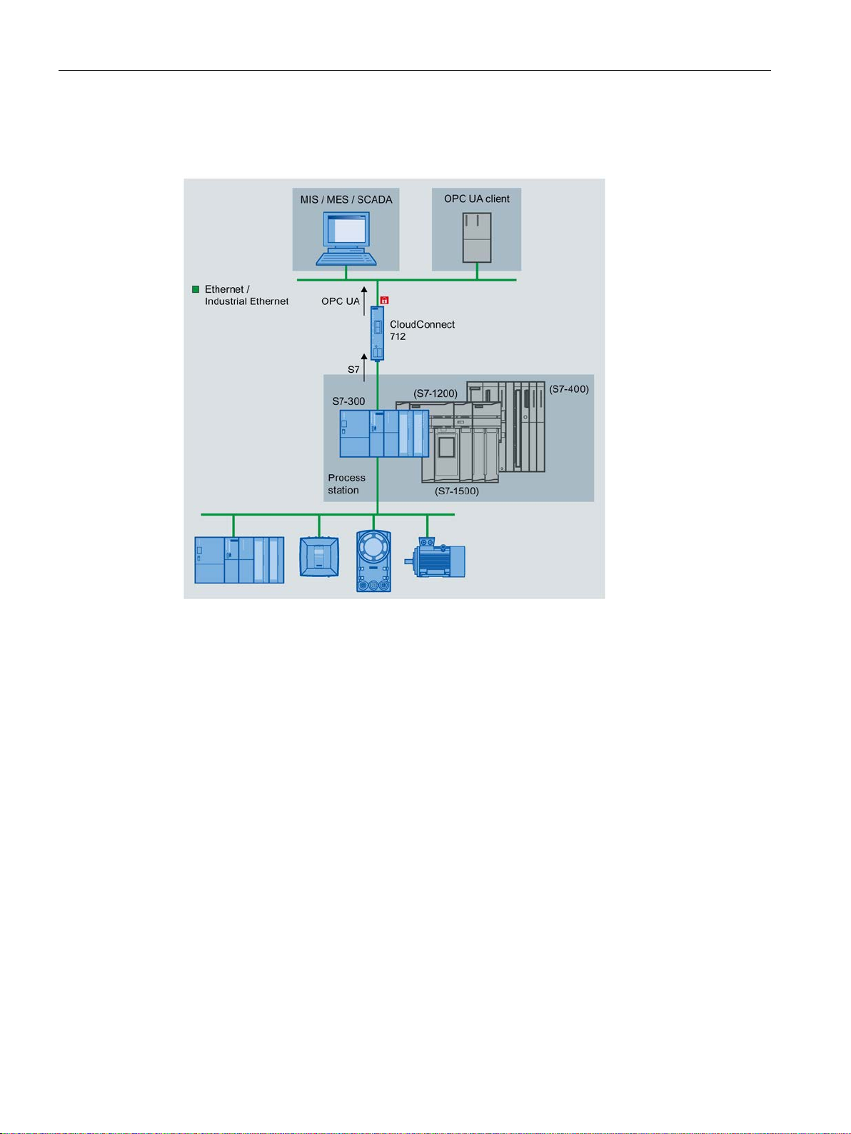
Below you will find examples of possible configurations with the "CloudConnect 7" gateway:
Connection of a process station to a cloud broker
In the configuration shown, the gateway reads process data from a process station and
transfer the data to a cloud broker using MQTT.
The process station is a SIMATIC S7-300 in this example. It can also be any other station
from the S7 product family.
A Modbus station, such as the programmable controller of a third-party supplier, can also be
connected.
● When it is connected to a SIMATIC S7, the gateway communicates using an S7
connection.
● When it is connected to a Modbus station, the gateway communicates using
Modbus/TCP.
Figure 1-1 CloudConnect 712 for connecting a station to the cloud
Connection of a process station to OPC UA clients
In the configuration shown, the gateway transfers process data over OPC UA to a central
control room or one or more OPC UA clients.
SIMATIC CC712
Operating Instructions, 05/2019, C79000-G8976-C503-01
13
Page 14
Application and functions
1.3 Configuration examples
The gateway reads process data from a S7 station and, as OPC UA server, makes it
available to one or more OPC UA clients.
Figure 1-2 CloudConnect 712 for connecting a station to OPC UA clients
SIMATIC CC712
14 Operating Instructions, 05/2019, C79000-G8976-C503-01
Page 15

Application and functions
1.4 Other services and properties
1.4 Other services and properties
Other services and properties
● IP configuration
– The gateway supports IP addresses according to IPv4 and IPv6.
– Address assignment:
The IP address, the subnet mask and the address of the default router can be set in
the configuration.
– DHCP: As an alternative, the IP address can be obtained from a DHCP server.
– Optionally, the host name can be ungrouped from a DNS server.
●
Time-of-day synchronization over Industrial Ethernet
Time-of-day synchronization of the gateway can be configured according to the following
NTP method (Network Time Protocol):
– NTP
– NTP (secure)
For more information, refer to the section System time (Page 87).
●
CLP (Exchangeable storage medium)
The gateway can save the configuration data on a CLP. The CLP is an external storage
medium and does not ship with the product.
For information on the CLP slot, see section CLP Slot (Page 24).
For information on the functions of the CLP, see section Using a CLP (Page 35).
For ordering data of the available CLPs, see appendix CLPs (Page 109).
●
Diagnostics
With the following means and methods, you can obtain the diagnostics data of the
gateway:
– LEDs
– Web diagnostics
You will find more information on diagnostics in the section Diagnostics (Page 93).
1.5 Configuration limits - communication
The gateway supports the following maximum quantity structure.
SIMATIC CC712
Operating Instructions, 05/2019, C79000-G8976-C503-01
15
Page 16

Application and functions
1.5 Configuration limits - communication
Connection resources over the process interface
● Number of connections to S7 stations
Max. 1 S7 connection to one S7 connection
●
Number of connections to Modbus stations
Max. 10 connections to Modbus stations
●
Number of connections to the configuration PC
Max. 1 HTTPS connection
Number of process data
● Tags in the data area of S7 CPUs
– Max. 500 tags
●
Tags per S7 CPU
– Max. 500 tags
●
Tags in the data area of Modbus stations
– Max. 100 tags per Modbus station
Connections over the Cloud interface
● Number of sessions with the broker
Max. 1 session
●
Number of connections to OPC UA clients
Max. 10 simultaneous sessions with OPC UA clients
OPC UA server
As OPC UA server, the gateway supports the following quantity structure.
●
Number of tags in the CPU data area
– Max. 500 symbols: / PLC tags
●
Number of supported subscriptions
– Max. 5 subscriptions per session
– In total maximum of 50 subscriptions at the same time
●
Number of items per subscription
– Max. 500 tags per subscription
– Max. 2500 tags over all subscriptions
SIMATIC CC712
16 Operating Instructions, 05/2019, C79000-G8976-C503-01
Page 17

Application and functions
1.6 Range of functions of the WBM
1.6 Range of functions of the WBM
Web Based Management (WBM)
You configure the gateway using its Web Based Management (WBM). The WBM consists of
Web pages that can be called up in the Web browser of a connected PC. From your PC you
connect to the WBM via HTTPS.
For information on the Web browsers that can be used on the PC, see section Scope of
delivery and requirements (Page 18).
Access to the WBM
To call the WBM, you need to establish a connection between the PC and the gateway via
LAN, see section Establishing a connection to the WBM (Page 42).
Overview of the functions of the WBM
The WBM provides the following functions:
●
User management
In the open WBM, you specify the user name and the password for the "Administrator"
role. You can only access the WBM with this administrator information.
●
Configuration
Using the WBM, configure the following function areas:
– Basic functions such as the time of day or IP address
– Connection of the process station
– Connection to the higher-level network (cloud, OPC clients)
– Communication functions
●
Maintenance and diagnostic functions
– Diagnostics
– Loading and storing the configuration data
– Downloading new firmware versions
Reusing the configuration file
The configuration data you create in the WBM is saved in the gateway.
If you want to back up the data as well, you can also save the configuration data in the WBM
area "Maintenance" on a CLP inserted in the gateway.
If you are using multiple gateways with partially identical configuration data, you can export
the configuration file of a gateway, copy it, and download it to additional gateways where you
can adapt it as needed.
SIMATIC CC712
Operating Instructions, 05/2019, C79000-G8976-C503-01
17
Page 18

Application and functions
1.7 Scope of delivery and requirements
1.7 Scope of delivery and requirements
Scope of delivery
The following positions ship with the gateway:
● Gateway "CloudConnect 7"
● Terminal block for power supply of the gateway
● Data storage medium with documentation
Required accessories
The following accessories (which do not ship with the product) are required for gateway
operation:
● Power supply
You need a 24 V DC external voltage source.
● PC
To configure the gateway, you need a configuration PC with suitable Web browser (see
below).
● LAN cable
For the connection of the configuration PC to the X2 LAN interface of the gateway, you
need a Cat 5 ITP cable.
Communication partner
● Process access
For process access you need a station in productive operation, alternatively:
– S7 station
– Modbus station
●
Cloud access / OPC clients
– For cloud access, you need the access set up to a cloud broker.
– You need at least one set up OPC UA client for connection via OPC.
Requirements in the S7 stations
The following requirements need to be met in your STEP 7 project or in the connected S7
stations.
● Tags / symbols
For access to the process data, tags or symbols must be created in the relevant CPU.
STEP 7 Professional: The "Optimized block access" option must be disabled in DBs. For
further details, see section Data points (Page 78).
SIMATIC CC712
18 Operating Instructions, 05/2019, C79000-G8976-C503-01
Page 19

Application and functions
1.7 Scope of delivery and requirements
● CPU 1200/1500
– Read protection cannot be configured under "Protection & Security" in the CPU.
– Access via PUT/GET must be configured under "Protection & Security" in the CPU.
● CPU 300/400
Read protection cannot be configured under "Protection" in the CPU.
● CP 300/400
The following requirements must be met on the CP for access to the station via a CP:
– "Module access protection" is configured as "Not locked".
– When "IP access protection" is configured, the IP address of the gateway must be
configured with the right "A".
● CP 1200
For access to the station via a telecontrol CP, S7 communication must be enabled on the
CP under "Communication types".
Web browser for the configuration PC
For access to the WBM of the gateway, the configuration PC needs one of the following Web
browsers.
● Apple Safari
● Firefox Quantum
● Google Chrome
● Microsoft Edge
● Microsoft Internet Explorer
The Web browser must accept cookies. The application uses a cookie.
JavaScript must be enabled in your Web browser.
Recommendation: Use the latest available version of the Web browser.
Optional
● CLP
Exchangeable storage medium for storing configuration data
● NTP server - can be reached over interface P1 / P2
● DHCP server - can be reached over interface P1
● DNS server - can be reached over interface P1
SIMATIC CC712
Operating Instructions, 05/2019, C79000-G8976-C503-01
19
Page 20

Application and functions
1.7 Scope of delivery and requirements
SIMATIC CC712
20 Operating Instructions, 05/2019, C79000-G8976-C503-01
Page 21
2
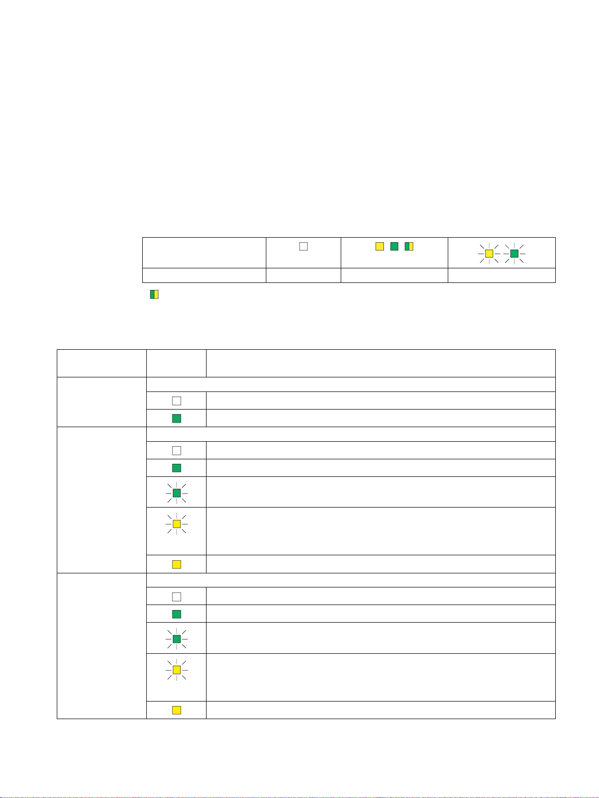
LED symbol
LED status
OFF
ON (steady light) *
Flashing
LED name
(colors)
LED pattern
Meaning / Module status
Power
Power supply
Device Connection
Connection to process stations
Cloud Connection
Connection to Cloud
2.1 LEDs
LEDs
The LEDs on the front show the states of the module.
The LED symbols in the table below correspond to the following states of the LEDs:
* : Part flashes yellow and part lit green
Meaning of the LED displays
(green)
(green / yellow)
(green / yellow)
Power OFF
Power ON
No connection to configured process stations
Existing connection to all configured process stations
No connection to at least one of the configured process stations
No communication with process stations Possible causes:
• Stop of communication over WBM ("Maintenance" tab)
• Incorrect configuration
No process station configured
No connection to cloud server
Existing connection to cloud server
Connection establishment to cloud server
No communication with process server Possible causes:
• Interruption of the communication
• Incorrect configuration
No cloud server configured
SIMATIC CC712
Operating Instructions, 05/2019, C79000-G8976-C503-01
21
Page 22
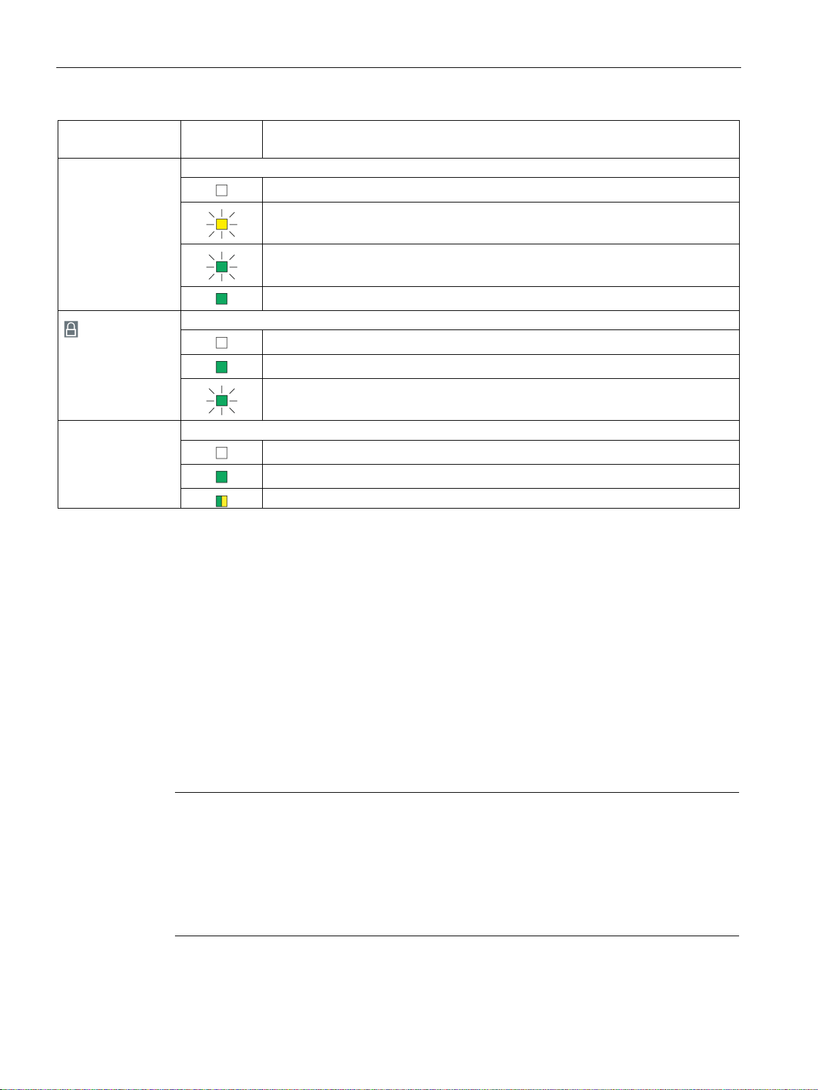
LEDs, Connectors, Buttons, CLP
LED name
(colors)
LED pattern
Meaning / Module status
Diagnosis
Diagnostics
Security
P1 / P2
Connection to Ethernet at interface P1 or P2
Existing connection with data traffic
Note
Connection to subnets
The two Ethernet interfaces are not designed as a switch,
different networks.
If the connection to the cloud is in the same subnet as the process connection, enable the
"Cloud interface in the same s
configuration.
2.2 Connections
(green / yellow)
No error
Error, diagnostic message available. (See WBM "Maintenance > Diagnostics messages")
Reset is initiated (button pressed during startup).
Reset is executed (button can be released).
(green)
(green / yellow)
No secure connection to cloud server / OPC UA clients configured
All connections to cloud server / OPC UA clients configured as secure
At least one unsecure connection to cloud server / OPC UA clients configured
No Ethernet connection
Existing Ethernet connection
2.2 Connections
2.2.1 Ethernet interfaces (P1, P2)
Ethernet interfaces
The gateway has two Ethernet interfaces according to Gigabit standard IEEE 802.3ab,
designed as RJ45 socket. They support autocrossing, autonegotiation and autosensing.
● P1
Cloud interface for connection of a cloud broker and OPC clients
● P2
Process interface for connecting the stations of the automation plant
but are intended for connection to
ubnet" option in the "Interface configuration" in the
SIMATIC CC712
22 Operating Instructions, 05/2019, C79000-G8976-C503-01
The pin assignment of the Ethernet interfaces and other data can be found in the section
Technical specifications (Page 99).
Page 23
LEDs, Connectors, Buttons, CLP
WARNING
EXPLOSION HAZARD
Note
Configuration data is deleted
By resetting to factory settings, the gateway is reset to the status as it was delivered from
the factory
2.3 The button "SET"
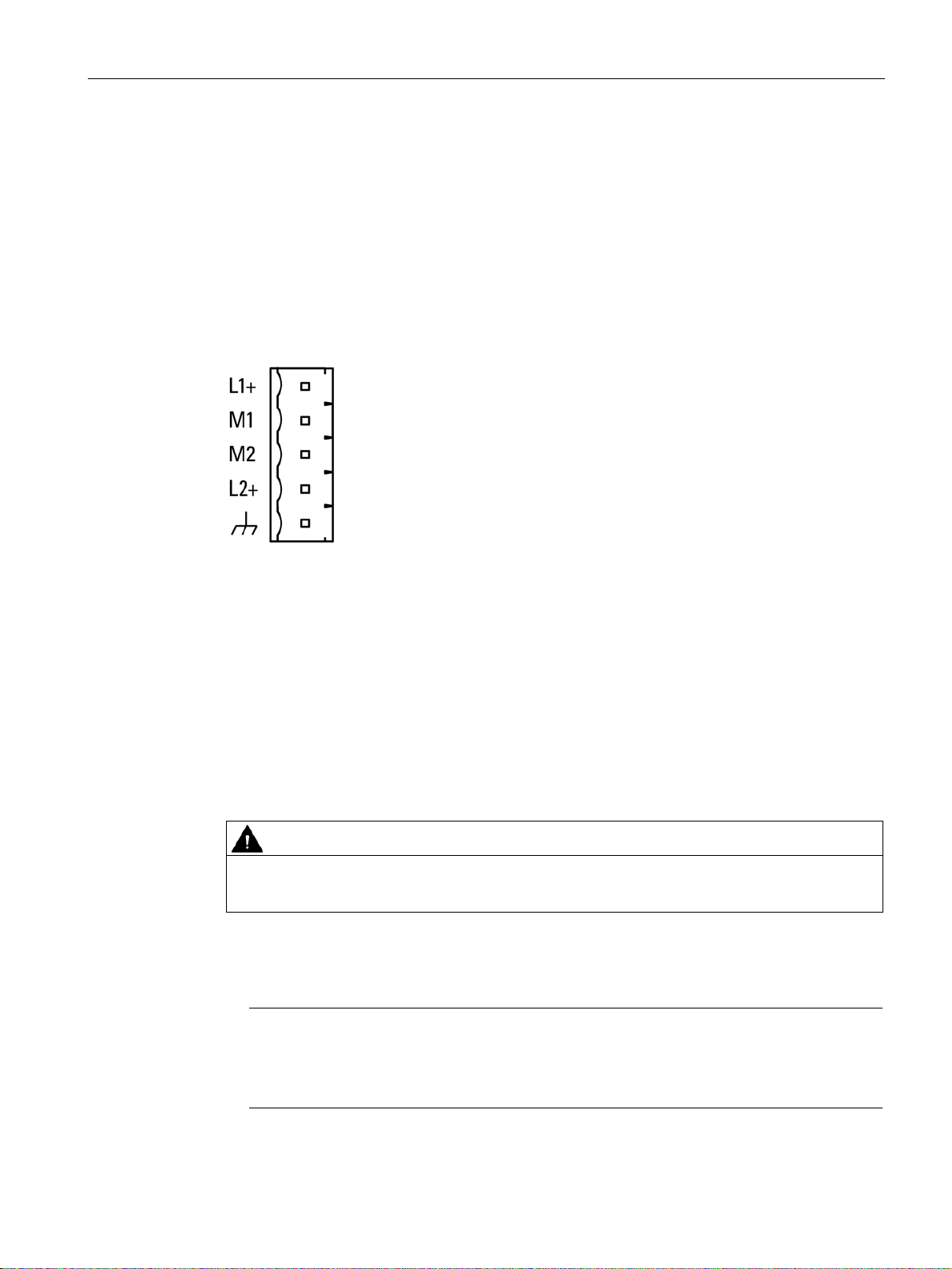
2.2.2 External power supply
External power supply
The connector (socket) for the external 24 V DC power supply is located on the front of the
gateway. The external power supply is redundant (optional use).
The power supply is connected to the gateway with the supplied 5-pin plug-in terminal block.
The connection has a mechanical reverse polarity protection. The terminal block is designed
so that it can only be inserted in one position into the socket of the gateway.
Figure 2-1 Socket of the external power supply
For information on allocation of the socket and for the connection, see section Connecting
(Page 33).
You will find further data on the power supply in section Technical specifications (Page 99).
2.3 The button "SET"
Functions of the button
Do not press the button if there is a potentially explosive atmosphere.
The "SET" button has the following functions:
●
Resetting to factory settings
. This deletes all the configured settings.
For the precise effects of resetting, refer to the section Reset (Page 96).
SIMATIC CC712
Operating Instructions, 05/2019, C79000-G8976-C503-01
23
Page 24

LEDs, Connectors, Buttons, CLP
Duration of pressing
the button (seonds)
Function and operation
Resetting to factory settings
address set at the factory.
2.4 CLP Slot
Pressing the button
≥ 5 s
1. Turn off the power supply.
2. Switch the power supply on again while pressing the button.
Hold down the button for at least 5 seconds during startup.
Reset is prepared while the "Diagnosis" LED flashes.
3. Release the button when the LED stops flashing.
While the LED lights up with a green steady light, the gateway performs the reset.
Once reset is complete, the gateway performs a restart and can be reached using the default IP
2.4 CLP Slot
The slot for an optional CLP is located on the back of the module.
For information on inserting and removing the CLP, see section Using a CLP (Page 35).
SIMATIC CC712
24 Operating Instructions, 05/2019, C79000-G8976-C503-01
Figure 2-2 Slot for optional CLP on the back of the device
Page 25
3
WARNING
WARNING
EXPLOSION HAZARD
WARNING
WARNING
WARNING
EXPLOSION HAZARD
3.1 Important notes on using the device
Safety notices on the use of the device
Note the following safety notices when setting up and operating the device and during all
associated work such as installation, connecting up or replacing the device.
If the device is installed in a cabinet, the inner temperature of the cabinet corresponds to
the ambient temperature of the device.
3.1.1 Notes on use in hazardous areas
Replacing components may impair suitability for Class 1, Division 2 or Zone 2.
The device may only be operated in an environment with pollution degree 1 or 2 as
described in IEC 60991-1.
The device may only be operated in an environment with pollution degree 1 or 2 (see
IEC 60664-1).
SIMATIC CC712
Operating Instructions, 05/2019, C79000-G8976-C503-01
Do not connect or disconnect cables to or from the device when a flammable or
combustible atmosphere is present.
25
Page 26
Installation, wiring, commissioning
WARNING
WARNING
WARNING
DIN rail
WARNING
Requirements for the cabinet/enclosure
WARNING
Cable
WARNING
3.1 Important notes on using the device
When used in hazardous environments corresponding to Class I, Division 2 or Class I,
Zone 2, the device must be installed in a cabinet or a suitable enclosure.
If a device is operated in an ambient temperature of more than 60 to 70 °C, the
temperature of the device housing may be higher than 70 °C. The device must therefore be
installed so that it is only accessible to service personnel or users that are aware of the
reason for restricted access and the required safety measures at an ambient temperature
higher than 60 °C.
3.1.2 Notes on use in hazardous areas according to ATEX / IECEx
In the ATEX and IECEx area of application only the Siemens DIN rail 6ES5 710-8MA11
may be used to mount the modules.
To comply with EC Directive 2014/34 EU (ATEX 114) or the conditions of IECEx, this
enclosure or cabinet must meet the requirements of at least IP54 (in compliance with
EN 60529) according to EN 60079-7.
If the cable or conduit entry point exceeds 70 °C or the branching point of conductors
exceeds 80 °C, special precautions must be taken. If the equipment is operated in an air
ambient in excess of 50 °C, only use cables with admitted maximum operating temperature
of at least 80 °C.
Take measures to prevent transient voltage surges of more than 40% of the rated voltage.
This is the case if you only operate devices with SELV (safety extra-low voltage).
SIMATIC CC712
26 Operating Instructions, 05/2019, C79000-G8976-C503-01
Page 27
Installation, wiring, commissioning
WARNING
LAN connection (Local Area Network)
WARNING
EXPLOSION HAZARD
WARNING
EXPLOSION HAZARD
WARNING
WARNING
Explosion hazard
3.1 Important notes on using the device
A LAN or LAN segment with all the interconnected devices should be contained completely
in a single low voltage power distribution system in a building. The LAN is designed either
for “Environment A” according to IEEE802.3 or "Environment 0" according to IEC TR
62102.
Do not connect any electrical connectors directly to the telephone network (Telephone
Network Voltage) or a WAN (Wide Area Network).
Do not press the SET button if there is a potentially explosive atmosphere.
3.1.3 General notices on use in hazardous areas according to UL HazLoc / FM
This equipment is suitable for use in Class I, Division 2, Groups A, B, C and D or nonhazardous locations only.
This equipment is suitable for use in Class I, Zone 2, Group IIC or non-hazardous locations
only.
You may only connect or disconnect cables carrying electricity when the power supply is
switched off or when the device is in an area without inflammable gas concentrations.
Do not remove or replace while circuit is live when a flammable or combustible atmosphere
is present.
Do not disconnect equipment when a flammable or combustible atmosphere is present.
SIMATIC CC712
Operating Instructions, 05/2019, C79000-G8976-C503-01
27
Page 28
Installation, wiring, commissioning
WARNING
EXPLOSION HAZARD
WARNING
WARNING
WARNING
Open equipment
WARNING
Cable temperatures
3.2 Installation
The equipment is intended to be installed within an ultimate enclosure. The inner service
temperature of the enclosure corresponds to the ambient temperature of the module. Use
installation wiring connections with admitted maximum operating temperature of at least
30 ºC higher than maximum ambient temperature.
Wall mounting is only permitted if the requirements for the housing, the installation
regulations, the clearance and separating regulations for the control cabinets or housings
are adhered to. The control cabinet cover or housing must be secured so that it can only be
opened with a tool. An appropriate strain-relief assembly for the cable must be used.
Substitution of components may impair suitability for Division 2.
3.2 Installation
The device is "open equipment" acc. to the standard UL 61010-2-201. To fulfill
requirements for safe operation with regard to mechanical stability, flame retardation,
stability, and protection against contact, the following alternative types of installation are
specified:
• Installation in a suitable cabinet.
• Installation in a suitable enclosure.
• Installation in a suitably equipped, enclosed control room.
If the cable or housing socket exceeds 70 °C or the branching point of the cables exceeds
60 °C, special precautions must be taken. If the equipment is operated in an ambient
environment in excess of 40 °C, only use cables with permitted maximum operating
temperature of at least 80 °C.
SIMATIC CC712
28 Operating Instructions, 05/2019, C79000-G8976-C503-01
Page 29

Installation, wiring, commissioning
NOTICE
Install and remove the device only when the power is off.
NOTICE
Installation location - Dependency of the temperature range
Minimum clearances
3.2 Installation
Switch off the power supply of the device before you install or remove the device. Installing
and removing devices with the power supply on can lead to damage to the devices and to
loss of data.
Installation options
You have the following options to install the gateway:
● Wall mounting
● Mounting on the following rail types (rack):
– DIN rail
– S7-1500 standard rail
– S7-300 standard rail
You can find suitable standard rails in the Siemens accessories program for automation
technology, for example:
35 mm standard mounting rail for 19" cabinets, article numbers 6ES5710-8MA11
● Mounting on pedestal
You can use the SCALANCE M pedestal "6GK5898-8MD00" for table mounting (does not
ship with the product).
Installation location
Note the dependency of the permitted temperature range of the installation location.
• Horizontal installation of the rack (DIN rail) means a vertical position of the modules.
• Vertical installation of the rack (DIN rail) means a horizontal position of the modules.
You will find the permitted temperature ranges in the section Technical specifications
(Page 99).
Mount the device so that its upper and lower ventilation slits are not covered, allowing
adequate ventilation as protection from overheating.
Keep to the following minimum clearances for the circulation of air when the rack is
installed horizontally:
• Above the device: At least 33 mm
SIMATIC CC712
Operating Instructions, 05/2019, C79000-G8976-C503-01
• Below the device: At least 25 mm
29
Page 30
Installation, wiring, commissioning
Installation of the rack
Installation position of the modules
3.2 Installation
Horizontal installation of the rack
Vertical installation of the rack
Wall mounting
1. Prepare the drill holes for wall mounting. For the dimensions, refer to the section
"Dimension drawings (Page 107)".
2. Secure the device to the wall with two screws (4 mm).
SIMATIC CC712
30 Operating Instructions, 05/2019, C79000-G8976-C503-01
Page 31
Installation, wiring, commissioning
NOTICE
Grounding
Note
Protecting the modules from slipping on the DIN rail
If you install the modules in an area with mechanical load, use suitable clamping devices at
both ends of the device group to secure the modules on the DIN rail, e.g. Siemens and
retainer 8WA1808.
The end retainers prevent the modules separa
3.2 Installation
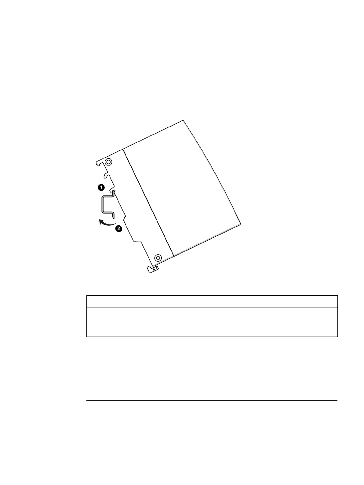
Installation on a DIN rail
1. Insert the device with the respective guide ① into the standard rail:
– Top guide for S7-1500 standard rail
– Center guide for S7-300 standard rail
– Bottom guide for DIN rail
2. Tilt the device to the back until the mounting rail release audibly locks in place
3. Ground the mounting rail.
②.
For reasons of electrical safety, the DIN rail must be connected to the protective conductor
system (PE) of the electrical system.
ting under mechanical load.
SIMATIC CC712
Operating Instructions, 05/2019, C79000-G8976-C503-01
31
Page 32

Installation, wiring, commissioning
3.2 Installation
Mounting on pedestal
1. Insert the device with the bottom housing guide on the top edge of the pedestal ①.
2. Press the device against the pedestal until the mounting rail release audibly locks in place
②.
Uninstalling
Follow the steps below to remove the device from the rail:
1. Turn off the supply voltage of the device.
2. Pull the power supply plug and the cables of the communication networks.
3. Pull down the mounting rail release on the rear of the device.
4. Tilt the device out of the standard rail.
SIMATIC CC712
32 Operating Instructions, 05/2019, C79000-G8976-C503-01
Page 33

Installation, wiring, commissioning
NOTICE
Suitable fusing for the power supply cable
Note
Protective ground
A PELV circuit contains a connection to protective ground. Without a connection to protective
ground, or in case there is a fault in the connection to the protective ground, the voltage for
the circuit is not stabilized.
WARNING
Power supply
3.3 Connecting
3.3 Connecting
The current at the connecting terminals must not exceed 4 A. Use a fuse for the power
supply that protects against currents > 4 A.
The fuse has to be designed for protection of DC power supply circuits as well as for the
following requirements.
• In areas used according to NEC or CEC:
– Suitable for DC (min. 60 V / max. 4 A)
– Cut-off voltage min. 10 kA
– UL/CSA listet (UL 248-1 / CSA 22.2 No. 248.1)
– Classes R, J, L, T or CC
• In other areas:
– Suitable for DC (min. 60 V / max. 4 A)
– Cut-off voltage min. 10 kA
– Approved for power supply circuits (branch circuits) according to local regulations
(e.g. IEC 60127-1, EN 60947-1)
– Breaking characteristics: B or C circuit breakers and fuses
You do not need a fuse for the power supply cable if you use a voltage source according
NEC Class 2 or a power supply from the range of accessories, see attachment Power
supply (Page 109).
The device is designed for operation with a directly connectable safety extra-low voltage
(SELV) and protective extra-low voltage (PELV) according to IEC 60364-4-41.
Recommendation: Use the power supply of a process station if this is in the vicinity of the
gateway.
SIMATIC CC712
Operating Instructions, 05/2019, C79000-G8976-C503-01
33
Page 34

Installation, wiring, commissioning
NOTICE
Connection only with power off
Note
The power supply unit of the device is not electrically isolated.
Terminal
Assignment
L1+
24 VDC
M1
Reference ground
L2+
24 V DC for redundant connection (optional)
3.3 Connecting
Order of the work
Only connect the device with the power switched off.
The device can be disconnected from the power supply with the terminal block.
Requirement: The device is mounted.
1. Connect the external power supply to the terminal block of the device.
2. Connect the cables of the two Ethernet networks to the interfaces of the device.
See the note in section Ethernet interfaces (P1, P2) (Page 22).
Turn the power supply on only after the device has been completely wired and connected.
The further procedure is described in the section Commissioning (Page 35).
Power supply
Use only copper cables for the power supply.
● Wire: 0.5 ...3 mm
● Stranded wire: 0.5 ...2.5 mm
2
(AWG 20 ...18)
2
● Tightening torque for screw terminals: 0.6 to 0.8 Nm
The 5-pin plug-in terminal block for the socket has a mechanical reverse polarity protection.
Table 3- 1 Pin assignment of the socket for the power supply
M2 Ground reference for redundant connection
Ground
You will find information about the connectable cable cross sections, power consumption
and further technical details in section Technical specifications (Page 99).
SIMATIC CC712
34 Operating Instructions, 05/2019, C79000-G8976-C503-01
Page 35

Installation, wiring, commissioning
3.4 Commissioning
3.4 Commissioning
3.4.1 Commissioning
Commissioning
1. Turn on the power supply after connecting it to the gateway.
2. Connect the configuration PC to the gateway for configuration, refer to the section
Establishing a connection to the WBM (Page 42).
If you want to use a CLP, turn off the power supply before you start configuring, insert the
CLP and turn on the power supply again.
Requirements for operation
At least the following requirements apply to operating the gateway:
● Configuration of the device
● At least one running process station
● A setup cloud service or OPC UA client
● Connecting the gateway to the networks of the communication partners
Applying the configuration data during commissioning
The "Apply" button
All saved configuration data that you create in the WBM is loaded into the gateway by
clicking the "Apply" button and used immediately. In this way, you can commission the
gateway step-by-step.
For information on the buttons of the WBM, see section General functions of the WBM
(Page 41).
3.4.2 Using a CLP
Exchangeable storage medium CLP
The gateway can be operated with an exchangeable CLP. The configuration data can be
stored on this exchangeable medium and this is retained if there is a power failure.
This exchangeable medium makes it easier to replace a damaged component or for any
other application of the gateway. By simply exchanging the plug, all data can be transferred
without having to be configured again.
The CLP is supplied with power by the gateway. The CLP retains all data permanently when
the power is turned off.
SIMATIC CC712
Operating Instructions, 05/2019, C79000-G8976-C503-01
35
Page 36

Installation, wiring, commissioning
Note
Use new CLPs
Only use a brand
eway. The gateway formats
a brand
CLPs that have already been used in other device types cannot be used for the gateway.
Note
Insert and remove only when power is off
The CLP may be inserted or removed only when the power is off!
3.4 Commissioning
-new CLP or a CLP that was formatted by a gat
-new CLP when it starts up with it.
Startup of the gateway with configuration file on CLP
When a configuration file is saved on the CLP and you insert the CLP into a gateway, the
gateway always starts up with the configuration data of the CLP.
By inserting a CLP into a brand-new gateway or a gateway that was reset to factory settings,
you can cause the gateway to always start up with the configuration file saved on the CLP.
Function
An unwritten CLP (factory state) is automatically formatted for the gateway on startup of the
device.
Inserting the CLP
The configuration of the gateway which you configure and apply is automatically backed up
on the CLP.
A device with an inserted CLP automatically uses the configuration data of the inserted CLP
when it starts up. This is, however, only possible when the data was written by a compatible
device type.
This allows fast and simple replacement of the basic device. If a device is replaced, the CLP
is taken from the failed device and inserted in the replacement. As soon as it starts up, the
replacement automatically applies the same device configuration as the failed device.
The slot for the CLP is located on the back of the device, see section CLP Slot (Page 24).
1. Turn off the power to the device.
2. Insert the CLP in the slot.
The CLP can only be inserted in one position.
Removing the CLP
1. Turn off the power to the device.
2. Insert a screwdriver between the front edge of the CLP and the slot and remove the CLP.
Diagnostics
General malfunctions of the CLP are signaled by the respective diagnostic message.
SIMATIC CC712
36 Operating Instructions, 05/2019, C79000-G8976-C503-01
Page 37

4
4.1 Security recommendations
Keep to the following security recommendations to prevent unauthorized access to the
system.
General
● You should make regular checks to make sure that the device meets the following
recommendations and other internal security guidelines if applicable.
● Evaluate your plant as a whole in terms of security. Use a cell protection concept with
suitable products.
● Check regularly for security updates of the products and use them.
● Check regularly for new features on the Siemens Internet pages.
– Here you will find information on industrial security:
Link: (http://www.siemens.com/industrialsecurity)
– Here you will find information on security in industrial communication:
Link: (http://w3.siemens.com/mcms/industrial-communication/en/ie/industrial-ethernet-
security/Seiten/industrial-security.aspx)
– You will find a publication on the topic of network security (6ZB5530-1AP0x-0BAx)
here:
Link:
(http://w3app.siemens.com/mcms/infocenter/content/en/Pages/order_form.aspx?node
Key=key_518693&infotype=brochures)
Enter the following filter: 6ZB5530
● Keep the software up to date. Always use the latest software version of the device.
– Information regarding product news and new software versions is available at the
following address:
Link: (https://support.industry.siemens.com/cs/ww/en/ps/15248/dl)
Physical access
Restrict physical access to the devices to qualified personnel.
Security functions of the product
Think about the services with which you want to enable access to the process stations via
public networks.
Use the options for security settings in the configuration of the product:
● Activate the security functions of the product and the devices involved.
● Use secure protocol variants (see below).
SIMATIC CC712
Operating Instructions, 05/2019, C79000-G8976-C503-01
37
Page 38

Configuration
4.1 Security recommendations
Passwords
● Define rules for the use of devices and assignment of passwords.
● Regularly update the passwords to increase security.
● Make sure that all passwords are protected and inaccessible to unauthorized personnel.
● Do not use one password for different users and systems.
Protocols
Secure and non-secure protocols
● Only activate protocols that you require to use the system.
● Use secure protocols when access to the device is not prevented by physical protection
measures.
– The NTP protocol provides a secure alternative with NTP (secure).
– Access to the Web server is only possible with HTTPS.
Server ports
The following table provides you with an overview of the open ports on this device.
●
Protocol / function
Protocols that the device supports.
●
Port number (protocol)
Port number assigned to the protocol.
●
Default of the port
– Open
The port is open at the start of the configuration.
– Closed
The port is closed at the start of the configuration.
●
Port status
– Open
The port is always open and cannot be closed.
– Open after configuration
The port is open if it has been configured.
●
Authentication
Specifies whether or not the protocol authenticates the communications partner during
access.
SIMATIC CC712
38 Operating Instructions, 05/2019, C79000-G8976-C503-01
Page 39

Configuration
Protocol / function
Port number (protocol)
Default of the port
Port status
Authentication
HTTPS
443 (TCP)
Open
Open
Yes
OPC UA server port
Note
Ensure that the PC and gateway are located in a protected network.
4.2 Overview of the WBM pages
Table 4- 1 Server ports
4840 (or individually
configured) (TCP)
Open when the server
is enabled.
Client ports
Make sure that you open port 443 in your configuration PC (HTTPS) as well as the required
client ports of the services used in the respective firewall in the subnet of the cloud in
intermediary routers/gateways.
This can be:
● Broker port
– MQTT unsecured: 1883 (TCP)
– MQTT via TLS: 8883 (TCP)
The port number can be set in WBM.
● NTP / 123 (UDP)
● DNS / 53 (UDP)
● DHCP / 67, 68 (UDP)
HTTPS connection over the process interface
For security reasons, you can only establish a connection to the WBM via the process
interface of the gateway from your PC.
Open after configuration
(server)
Yes, when security is
enabled.
The cloud interface is blocked for access to the WBM.
4.2 Overview of the WBM pages
Opening the WBM pages
All page titles that you need for navigation through the WBM are located at the top of each
WBM page.
Open a WBM page by clicking the page title.
SIMATIC CC712
Operating Instructions, 05/2019, C79000-G8976-C503-01
39
Page 40

Configuration
4.2 Overview of the WBM pages
The WBM tabs
The following list provides an overview of the WBM pages and their functions.
● Start page (Page 45)
– Info
The page provides an overview of important status and configuration data of the
gateway.
● Interface configuration (Page 46)
– Configuring the gateway interfaces
● Process access (Page 48)
– Configuration of the process access (SIMATIC S7 / Modbus/TCP)
● OPC UA (Page 52)
– Configuring the OPC UA server
● Cloud configuration (Page 59)
– Configuring the cloud access
– Configuring the MQTT settings
– Certificate management
– Configuring the topics/groups and the user data format
● Data points (Page 78)
– Configuring the data points of the process stations
● Maintenance (Page 87)
– Time-of-day synchronization / setting the time
– User management
– Firmware update
– Configuration backup
– Process communication, restart
– Diagnostic messages
– Exporting logging data
SIMATIC CC712
40 Operating Instructions, 05/2019, C79000-G8976-C503-01
Page 41
Configuration
Symbol
Function
Runtime system is restarted with the applied settings.
Symbol
Function
4.3 General functions of the WBM
4.3 General functions of the WBM
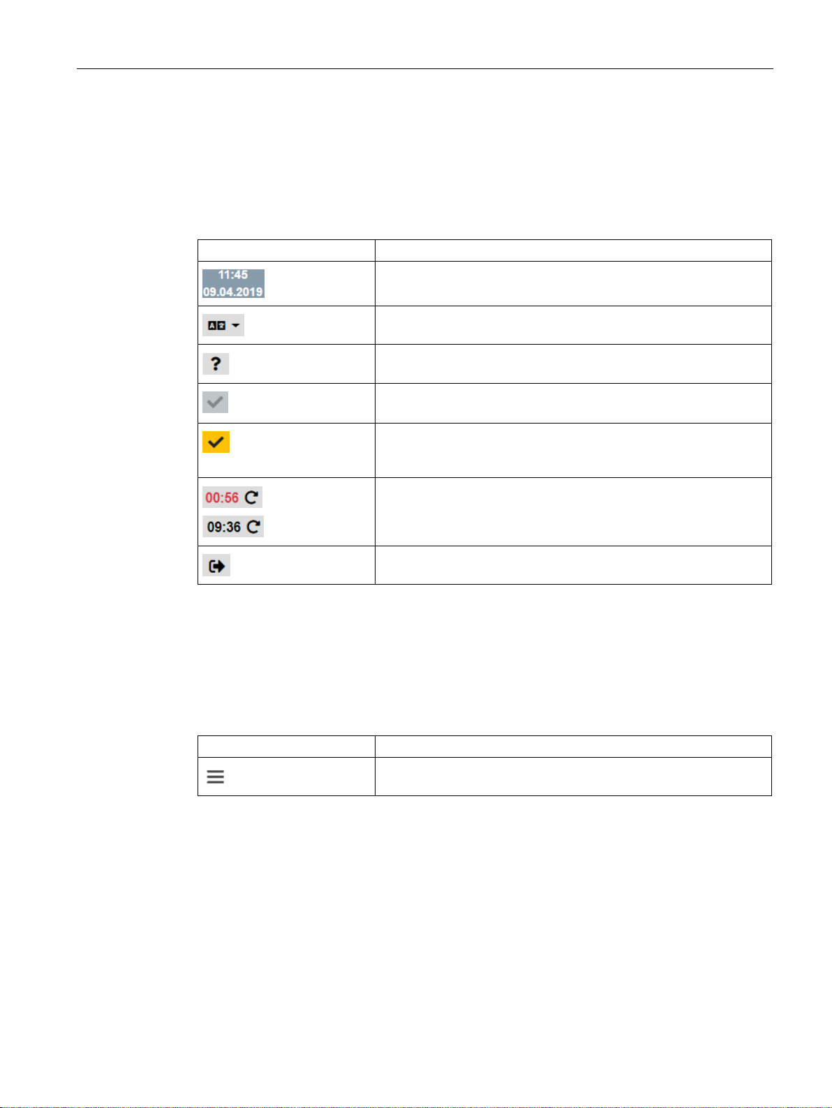
Symbols in the toolbar
You can reach the following functions using the displays and symbols in the toolbar:
Time and date of the runtime system
Switching the WBM language
Opens the online help of the WBM.
Apply
All saved data is applied to the Runtime system.
Apply
Applies saved configuration data to the Runtime system. The
Menu bar
Save
Counter which displays the remaining time of the current session.
By clicking the time display, the counter of the session duration is
reset.
Log off: Ends the connection to the WBM
The menu bar shows the tabs of the WBM over which you reach the different pages of the
WBM.
When you minimize your browser window, the display of the tabs disappears and the
following symbol is displayed:
Shows the tab titles as navigation with a minimized browser window.
Confirm all your entries by clicking the "Save" button. Your settings are thus saved to the
buffer.
The saved configuration data is not applied by the device yet by saving. This prevents
inconsistent changes from being loaded to the Runtime system when the WBM page is
changed.
SIMATIC CC712
Operating Instructions, 05/2019, C79000-G8976-C503-01
41
Page 42

Configuration
Note
IP address of the CP
By default, the DHCP client of the gateway is disabled. Make sure that the PC has a fixed IP
address during the first connection setup and that it is located in the same subnet as the
connected interfac
When using a DHCP server you do not need to specify the addressing on the PC to be
connected. When it is connected to the network, the PC is assigned an address.
4.4 Calling the WBM
Application to the runtime system
All saved configuration data is applied to the Runtime system by clicking on the "Apply"
symbol.
Incorrect entries in the configuration
The input boxes of the WBM are checked during input for faulty content and consistency.
Notes are output for boxes with detected errors during saving. The settings can only be
saved after the error has been corrected.
Grayed out fields cannot be edited.
4.4 Calling the WBM
4.4.1 Establishing a connection to the WBM
Requirements
You can establish a connection between a PC and the gateway via HTTPS:
You can establish a connection over the P2 interface of the gateway.
The condition for access to the gateway is that the PC is located in the same subnet and that
the gateway can be reached.
First connection setup with preset IPv4 address
Use the following preset IPv4 address of the gateway during the first connection setup:
● P2 interface address: 192.168.0.55
e of the gateway.
SIMATIC CC712
42 Operating Instructions, 05/2019, C79000-G8976-C503-01
Page 43

Configuration
Note
Changing standard user data
For security reasons,
must be changed when you log i
User data
Default values set in the factory
User name
admin
Password
admin
4.4 Calling the WBM
Connection to the Web server of the gateway
Follow the steps below to connect the PC to the Web server of the gateway:
1. Open the Web browser.
2. Enter the IP address of the gateway in the address line of the Web browser:
– https://<Address>
With HTTPS connections when you log in, a warning can appear that the Web page is
not secure or that the certificate is not trustworthy. If you are sure that you have entered
the correct address, ignore the message. If necessary add the connection to the
exceptions (depending on the Web browser).
When the connection setup is successful, the logon window of the WBM opens.
4.4.2 Logging into the WBM
HTTPS connection
Only HTTPS connections are supported.
You can establish a connection between a PC and the WBM of the device.
Changing standard user data
Standard user data for the first login to the WBM is preassigned by the system:
An administrator can be set up with all available rights for operation of the WBM.
the factory set user data (user name, password) of the standard user
n the first time, see section User (Page 89).
SIMATIC CC712
Operating Instructions, 05/2019, C79000-G8976-C503-01
43
Page 44

Configuration
Note
Entering the wrong user name or password
After entering an incorrect user name or incorrect password three times a lockout time of a
few minutes begin
4.4 Calling the WBM
Logging in
After establishing a connection between the PC and the device, the WBM opens with the
logon page.
s. Only after the lockout time has expired can you try to log in again.
● User name
Enter the user name here.
●
Password
Enter the password here.
●
Logging in
Click the button to set up the connection to the WBM.
When you log in for the first time, you are prompted to change the default user data. You can
find the rules for password assignment in the section User (Page 89).
Open Source Software and links to additional information
You can find the following links at the bottom of the login page:
●
Help
Opens the online help of the WBM.
●
Open Source Software
Opens the license terms document for the Open Source Software.
If necessary, you can save the document on your PC.
●
Siemens
Opens the Siemens AG homepage.
4.4.3 Log out
Manual logout using the button
You log out from the WBM by clicking on this button in the toolbar.
The connection to the device is terminated. All changes to the configuration data not saved
previously are lost.
SIMATIC CC712
44 Operating Instructions, 05/2019, C79000-G8976-C503-01
Page 45

Configuration
4.5 Start page
Automatic logout after timeout
After 600 seconds without saving or changing the WBM page, you are logged out and
disconnected from the WBM. In this case, you must log in again.
In the WBM toolbar you can see the counter in the upper right-hand corner which displays
the remaining time of the current session. By clicking the time display, the counter of the
session duration is reset and the time of the session duration starts all over again.
4.5 Start page
4.5.1 Info
The page provides an overview of important status and configuration data of the device.
Status
Process interface
● Operating state
Operating state of the device
●
System runtime (dd-hh-mm-ss)
Time since the last startup (dd-hh-mm-ss)
●
Hardware product version
Hardware product version of the device
●
U-Boot version
Current U-Boot version for the firmware bootloader
●
Software version
Current firmware version of the device
●
Serial number
Serial number of the device
The parameter group displays the current address data of the P2 interface.
●
MAC address
●
IPv4
Address parameters, Default router
SIMATIC CC712
Operating Instructions, 05/2019, C79000-G8976-C503-01
45
Page 46

Configuration
Address data preset in the factory
Process interface (P2)
Cloud interface (P1)
IPv4 address
192.168.0.55
192.168.121.55
IPv6 address
-
-
Subnet mask
255.255.255.0
255.255.255.0
4.6 Interface configuration
Cloud interface
The parameter group displays the current address data of the P1 interface.
●
MAC address
●
IPv4 / IPv6
Address parameters, Default router
DNS server
The parameter group shows the IPv4 addresses of up to two configured DNS servers.
4.6 Interface configuration
4.6.1 Ethernet
In this tab, you configure the address data of the Ethernet interfaces of the device.
Interface and factory default addresses
You configure the following interfaces on the web pages:
● Process interface (P2)
The interface (P2) is used for connecting to the subnet of the process stations.
● Cloud interface (P1)
The interface (P1) is used for connecting to the Internet or to a router over which the
broker or the network with OPC UA clients can be reached.
The device supports IPv4 addresses, and for cloud access also IPv6 addresses.
The following address data is preset in the factory:
Table 4- 2 Preset address data
Host name CloudConnect7 CloudConnect7
SIMATIC CC712
46 Operating Instructions, 05/2019, C79000-G8976-C503-01
Page 47

Configuration
Note
No address check
The address bands are not checked automatically.
Make sure that the subnets of the two interfaces are not the same.
Note
No reachability when IP address data of the process interface is applied
The IP parameters of the process interface must match the settings of the IP address
data of your PC.
Note
DHCP server
The devi
function, a DHCP server must be located in the subnet.
The factory preset host name of the device is transferred to the DHCP server, see table
"Preset address data" above.
4.6 Interface configuration
Process interface / Cloud interface
You configure both interfaces separately.
●
Cloud interface in the same subnet
You can find this option under the parameter group of the Cloud interface.
Only enable the option if the connection to the cloud is in the same subnet as the process
connection.
When the option is enabled, the Cloud interface is disabled and the corresponding input
fields are locked.
The following parameters apply to both interfaces.
●
MAC address
MAC address of the interface
●
IPv4 / IPv6
Enable the respective IP address.
Alternatively, the Cloud interface supports IPv6 addresses.
● IP address
Shows the preset, last configured or the last IP address to be obtained from the DHCP
server.
During the initial configuration: Assign the IP address of the respective interface or
activate addressing by a DHCP server.
●
IP address via DHCP
Enable the option if you want to obtain the address data of the Cloud interface from a
DHCP server.
When the option is enabled, the address data boxes are grayed out, and the values
obtained from the DHCP server are displayed.
ce supports the DHCP client function at the cloud Cloud interface. To use the
SIMATIC CC712
Operating Instructions, 05/2019, C79000-G8976-C503-01
47
Page 48

Configuration
4.7 Process access
● Subnet mask
Shows the preset, last configured or the last subnet mask to be obtained from the DHCP
server.
During the initial configuration: Assign the subnet mask of the respective interface.
●
Default router
Shows the configured IP address of the router being used or the one last obtained with
DHCP.
During the initial configuration: Assign the IP address of the router.
DNS server
● DNS server
You have the option of configuring the IP addresses of up to two DNS servers. The DNS
servers can be located in the subnet that is connected to the Cloud interface.
With activated DHCP server, the obtained IP addresses of the DNS server are displayed.
If no DNS server is used, the address box is empty.
4.7 Process access
4.7.1 Station configuration
Add station
Here you create new process stations as communication partners.
●
Station name
To create a new station, enter a unique name in the input box.
●
Add
Creates a new station with the previously entered name in the configuration data of the
gateway.
SIMATIC CC712
48 Operating Instructions, 05/2019, C79000-G8976-C503-01
Page 49

Configuration
Note
Accidental deletion
If you accidentally delete a station, you cannot undo the deletion.
4.7 Process access
Station configuration
● Select station
Select one of the created stations to configure its settings.
●
Protocol
Select the protocol type for the selected station:
– S7
– Modbus/TCP
After selecting the protocol, click on the tab "S7" or "Modbus/TCP". The configurable
parameters for this station are displayed.
●
Delete station
By clicking the button, the selected station is deleted.
S7
The gateway and the SIMATIC S7 station communicate over S7 connections. The
connection type is TCP. The gateway is the active partner during connection setup.
Requirement:
● PUT/GET communication must be activated in the S7 CPU.
● The "Optimized access" option must be deactivated for data blocks of the CPU that are
accessed by the gateway.
You do not necessarily have to create a connection at the station end for the gateway to
communicate with the S7 station. The CPU reserves connection resources to unspecified
partners.
If you nevertheless want to create fixed connections, disable the "Active communication
establishment" option in the connection properties. In this case, write down the TSAP of the
connection assigned by STEP 7 for each station.
●
IP address
IPv4 address of the station interface (CPU or CP)
●
Controller family
Select the controller family of the connected station from the drop-down list:
– S7-1200/1500
– S7-300/400
SIMATIC CC712
Operating Instructions, 05/2019, C79000-G8976-C503-01
49
Page 50

Configuration
4.7 Process access
● Standard TSAPs
When the option is enabled, the device uses the standard TSAPs for its local TSAP and
the remote TSAP (S7 CPU). The standard settings for the remote TSAP are intended for
the case that you have not configured a connection to the gateway in the STEP 7 project.
TSAPs are entered as hexadecimal values. For an S7-300/400, the TSAP references the
rack, the slot and the type of CPU connection resource.
Examples for an S7-300 CPU:
– TSAP: 11.02
Rack 0, slot 2, connection resource 11
– TSAP: 03.02
Rack 0, slot 2, connection resource 03
Connection configured at one end (Local end point "One-way") Connection partner
"unspecified"; the gateway as connection partner is not configured.
A connection resource for a connection configured at one end with unspecified partner
has the value 03.
A connection resource for a connection configured at both ends with unspecified
partner has the range of values 0x10...0xDF.
The following standard TSAP IDs are used:
– Local TSAP of the gateway: 01.01
– Remote TSAP of the controller family:
- S7-1200/1500: 02.01
- S7-300/400: 03.02
Disable the option if the remote TSAPs do not match the preset standard TSAPs. In this
case, configure the TSAP that is assigned in the STEP 7 project.
●
Local TSAP
Range of values: 01.01 ... 7E.7E
We recommend using the default TSAP (01.01).
●
Remote TSAP
Enter the TSAP of the S7 connection assigned in STEP 7 at the station end if you have
configured a connection with an unspecified partner in the CPU for the gateway.
●
Polling cycle (ms)
Cycle time in milliseconds in which the gateway reads the data from the station.
Range of values: 1...1 000 000 000
SIMATIC CC712
50 Operating Instructions, 05/2019, C79000-G8976-C503-01
Page 51

Configuration
4.7 Process access
Modbus/TCP
The gateway and the Modbus station communicate over Modbus/TCP connections. The
gateway is the active partner during connection setup.
●
RTU number
RTU number of the Modbus slave
●
IP address
IPv4 address of the station interface
●
Port number
Port number of the station interface. Default: 502
●
Connection establishment attempts
Maximum number of attempts to establish a connection to a station.
After reaching the configured number of attempts, no additional connection attempts are
made until the gateway is restarted.
Range of values: -1...32768
With "-1" the number of connection attempts is unlimited.
●
Polling interval (s)
Cycle time in seconds in which the gateway reads the data from the station.
Range of values: 1...65535
●
Reconnection delay (s)
Wait time (seconds) before a new connection attempt is made when the station cannot be
reached or the connection is terminated.
A wait time makes sense, for example, to wait for short-term network faults to be removed
or restart of a station.
Range of values: 0...100
●
Timeout (ms)
When the gateway does not receive a response from the station within the configured
time (milliseconds), it repeats the station request.
Range of values: 100...65535
●
Max. number of faulty responses
Maximum number of outstanding or faulty station responses.
When reaching the maximum number, the gateway considers the station to be faulty and
terminates the connection. When a connection is terminated, the gateway tries to reestablish the connection.
Range of values: 1...32
SIMATIC CC712
Operating Instructions, 05/2019, C79000-G8976-C503-01
51
Page 52

Configuration
4.8 OPC UA
● Retries
Maximum number of retries of the station query when the gateway does not receive any
or a faulty response from the station.
Range of values: 0...10
●
Endianness
You use this option to specify the order in which the data of the station read word by word
is saved.
– Big Endian
The higher byte 1 is saved first. (Modbus standard)
– Little Endian
The lower byte 0 is saved first.
Numbering of the two bytes of a word: | 1 | 0 |
4.8 OPC UA
4.8.1 OPC UA server
Requirements
CPU tags
The process data that the gateway makes available to the OPC UA services, originate in the
connected S7-CPU. You will find the permitted memory areas of the CPU and the supported
data types in the section Data points (Page 78).
A data point that is configured for OPC UA cannot be configured for transfer to a cloud
broker.
The data point names assigned during data point configuration are included in the NodeID of
an item as part of the identifier, see section Properties of the OPC UA server (Page 58).
Note:
Where possible read tags in in data blocks block by block per DB to achieve a higher speed.
Security settings of connected clients
If you use the gateway as an OPC UA server and the communication partners (UA clients)
you are using demand a certificate, you must create or import a self-signed server certificate.
SIMATIC CC712
52 Operating Instructions, 05/2019, C79000-G8976-C503-01
Page 53

Configuration
4.8 OPC UA
OPC UA server
● Host name (optional)
Optional input box for a host name that is to be used instead of the IP address.
If you do not want to use a host name, leave the box empty.
●
Application URI
Unique OPC UA server URI of the gateway with the following preset components:
<Scheme (Protocol)>:<Authority (Server)>:<Path>
Default:
– urn:Siemens:UA:CC7
The protocol part (urn) must not be changed; the other components can be configured.
●
Application name
Name of the OPC UA application of the gateway. The application name is required for
display of the OPC UA server at the clients.
Default:
– SIMATIC Cloud Connect 7 OPC UA Server
●
Enable OPC UA server
Select the option to enable the OPC UA server function of the gateway.
●
Server address (IPv4) / (IPv6)
The two boxes for the IPv4 and the IPv6 address are displayed.
Server settings
● Port number
Here, you can change the port number of the server application. As default port number
4840 is used, the standard TCP port for the OPC UA binary protocol.
Permitted port numbers are as follows:
– 2000 .. 4499
– 4501 .. 34963
– 34965 .. 49151
●
Min. publishing interval (ms)
Here you set the minimum publishing interval that the server application of the gateway
should support. Lower values requested by OPC UA clients are not taken into account.
The OPC UA server provides the clients with the UA data in the cycle of the publishing
interval.
Range of values: 100 .. 65535 ms
Default setting: 500 ms
SIMATIC CC712
Operating Instructions, 05/2019, C79000-G8976-C503-01
53
Page 54

Configuration
4.8 OPC UA
● Min. sampling interval (ms)
Here you set the minimum sampling interval that the server application of the gateway
should support. Lower values requested by OPC UA clients are not taken into account.
The OPC UA server of the gateway samples its internal process image with the sampling
interval.
You specify reading from the station with the polling cycle, see section Station
configuration (Page 48).
The default is suitable for most applications. A smaller sampling interval can be selected
for reading fewer data points when the polling cycle is configured with a smaller value as
well.
Range of values: 100 .. 5000 ms
Default setting: 500 ms
4.8.2 OPC UA Security
Security mechanisms
The gateway supports the following security profiles in accordance with the OPC UA
specification:
●
SecurityPolicy
It determines the signing and encryption of the transferred data.
●
UserToken
Enables authentication using certificates.
●
Authentication of the communications partners with user name and password
See section Authentication (Page 58) for more on this.
For information on the OPC UA profiles of the OPC Foundation, see:
Profiles (https://apps.opcfoundation.org/ProfileReporting)
Server security
First you specify with the first two options whether the OPC UA server of the gateway is to
use a self-signed or an imported certificate.
●
Use self-signed certificate
Select this option when the gateway is to use a self-signed server certificate.
When the option is enabled, the corresponding GUI elements are shown:
– Created server certificate
Shows the name of the created certificate.
–
+
Opens the following dialog for configuring the certificate to be created:
SIMATIC CC712
54 Operating Instructions, 05/2019, C79000-G8976-C503-01
Page 55

Configuration
4.8 OPC UA
"Create new certificate"
In this dialog, you configure the parameters of the certificate you are going to create.
Note:
Ensure the consistency with the configuration data of the OPC UA server in section OPC
UA server (Page 52).
– Issuer
Issuer of the certificate. Default: Siemens
– Common name of subject (CN)
Application name of the gateway
– Signing Algorithm
Select the required hash algorithm and the encryption method.
– Validity period (days)
Enter the required period of validity.
– Subject alternate name (SAN)
As alternative name (SAN), you can specify the IP address, the host name, the URI or
an e-mail address of the gateway.
The IP address or the host name and the URI must be configured.
URI of the gateway with the following default components:
<Scheme (Protocol)>:<Authority (Server)>:<Path>
Default: urn:Siemens:UA:CC7
The protocol part (urn) must not be changed; the other components can be
configured.
●
Import server certificate and private key
Select this option if you want to import the server certificate and the key into the gateway
as an alternative.
Requirement: The files are saved on your PC.
When the option is enabled, the corresponding GUI elements are shown:
– Import server certificate / Import private key
Shows the name of the selected certificate or key file in the file system.
– Browse
Opens the browser for browsing your PC file system.
– Imported server certificate / Imported private key
Shows the name and path of the last imported certificate or key file.
You can delete the respective file with the "Delete" symbol.
SIMATIC CC712
Operating Instructions, 05/2019, C79000-G8976-C503-01
55
Page 56

Configuration
4.8 OPC UA
● Security Policy
Select the required option in the table.
If you enable several options, then the client selects a suitable profile depending on the
settings on the gateway.
The gateway supports the following options of the SecurityPolicy:
– None
– Basic128Rsa15
Signing and 128-bit encryption
– Basic256
Signing and 256-bit encryption
– Basic256Sha256 (SecurityPolicy [B])
Signing and 256-bit encryption (SHA-256)
The supplementary Conformance Units (Signing / Encryption) mean:
– Sign
Trusted clients
The gateway only allows communication with signed frames.
– Sign and encrypt
The gateway only allows communication with signed and encrypted frames.
● No certificate validation
With this option you disable the validation of the partner certificates.
When this option is enabled, the gateway generally permits communication even if the
criteria of the certificate validation listed below are not met or when the client certificate is
not included in the list of trusted clients.
When the option is disabled, the gateway validates the certificates of its partners, except
if "SecurityPolicy - None" is selected.
For information on the check mechanisms, refer to the "Certificate validation" section
below.
●
Import client certificate > Browse
You use this option to import the certificates of communication partners you trust.
Requirement for import of a certificate is that it is available in the PC file system.
Imported certificates are displayed in a table with their parameters.
SIMATIC CC712
56 Operating Instructions, 05/2019, C79000-G8976-C503-01
Page 57

Configuration
4.8 OPC UA
● Imported client certificates
The following parameters are displayed:
–
File
The name and path of the certificate file are displayed.
–
Issuer
Certificate authority that issued the certificate.
–
Certificate owner (CN)
Name of the device (or certificate authority) for which the certificate was issued.
–
Valid from
Start date of the period of validity of the certificate
–
Valid to
End date of the period of validity of the certificate
–
Finger print
Finger print (Digest) of the certification data
Certificate validation
The UA server of the gateway checks the certificates of its communication partners when the
"No certificate validation" option is disabled, except if "SecurityPolicy - None" is selected.
If a partner certificate is invalid or is not trustworthy, communication is aborted.
Communication is aborted in the following cases:
● The IP address of the communications partner is not identical to the IP address in its
certificate.
● The use stored in the certificate (OPC UA client/server) differs from the function (OPC UA
client/server) of the communications partner.
● The current time on the gateway is outside the period of validity of the partner certificate.
Requirements for connection setup
The following requirements must be met to set up a connection regardless of the certificate
validation:
● The application URI sent by the requesting client must match the URI of the server
application of the gateway.
● If the partner certificate is not trustworthy, the gateway must at least have stored a self-
signed certificate of the partner.
● At least one authentication option is enabled (see below).
The gateway does not support partner certificates that were issued by multiple CAs
(certificate chains).
SIMATIC CC712
Operating Instructions, 05/2019, C79000-G8976-C503-01
57
Page 58

Configuration
4.8 OPC UA
4.8.3 Authentication
Authentication
You use the two options to set the access authorization of the communication partners
(clients) to the OPC UA data of the gateway.
●
Enable anonymous access
Clients can access the OPC UA data without authentication.
●
Authentication via user name and password
Clients can access the OPC UA data only with authentication.
Note:
If none of the two options is enabled, no connection is established.
●
Add user
With enabled "Authentication via user name and password" option, you use this button to
open the input boxes for a new user.
●
User name
User name of the communication partner
●
Password
Password of the communication partner
The user data must be configured for the respective client.
4.8.4 Properties of the OPC UA server
Identification and addressing
Addressing and identification features of the OPC UA server of the gateway:
● Application name, Application URI, Server URL, Port number of the application
See section OPC UA server (Page 52).
● Namespace of the gateway data points
– CC7
● NodeID - Identifier
The identifier of the NodeIDs of the data points of the "CC7" namespace is formed by the
server application of the gateway from the name of the CPU and the data point name:
– <
CPU name
>.<
Data point name
>
Subscriptions
For the number of subscriptions supported by the gateway as OPC UA server for
MonitredItems, see section Configuration limits - communication (Page 15).
SIMATIC CC712
58 Operating Instructions, 05/2019, C79000-G8976-C503-01
Page 59

Configuration
4.9 Cloud configuration
The data management of the subscriptions is stored in the RAM of the gateway.
If there is power down, all data and connection information of subscriptions is lost. After
restarting the server, the client needs to re-establish the connection and set up the
subscriptions again.
Deadband
When monitoring items in the "DataChangeFilter", the OPC UA server of the gateway uses
the filter "AbsoluteDeadband".
4.9 Cloud configuration
4.9.1 Notes on structuring data
Data structures
Depending on the cloud provider, the data is structured differently for transfer to the broker:
● AWS / Azure / IBM Cloud
– Topics
A topic is the channel for the transfer of values of one or more data points.
You can create several topics.
No groups can be configured.
● MindConnect IoT Extension / Other Cloud
– Groups
A group can contain one or multiple data points.
You can create one or more groups.
– Topic
You can assign different topics to the groups.
MindConnect IoT Extension: In the default setting, the groups are assigned to the
standard topic "s/us" of the MindConnect IoT Extension.
Structure of the topic names
Because the requirements on the format of the topics can be different depending on the
receiver (broker, cloud), a topic name is made up of different parts.
Prefix and suffix generally apply to all topics.
Prefix and suffix are not relevant for groups.
SIMATIC CC712
Operating Instructions, 05/2019, C79000-G8976-C503-01
59
Page 60

Configuration
4.9 Cloud configuration
Structure of the topic names:
●
Prefix
The prefix of the name is an addressing and structuring string.
●
Topic name
– For the cloud provider MindConnect IoT Extension, the topic name "s/us" is a fixed
name.
– For all other cloud providers, the topic names can be configured.
By inserting multiple name components separated by forward slashes (/), you can
create hierarchy levels for later evaluation by the subscriber.
●
Suffix
The suffix of the name is a format string.
Name assignment for topics and groups
Because the topic or group names are incorporated in the data management structure of the
broker, later assignment and evaluation of the published data is facilitated if the names refer
to the process data of the stations.
Example:
You would like to name a group or topic "Motor5" and assign the name "Station1" to the
station. In this case, the following entry, for example, would be suitable for the topic name or
group name:
Station1/Motor5
4.9.2 Profile
4.9.2.1 Profile
The settings that you configure for the cloud access of the gateway are stored in a profile.
This will make it easier to use the device for different scenarios. Individual settings for
different scenarios can thus be summarized in different profiles without the need to change
the configuration every time you change the cloud.
Previously configured profiles are available in the "Profiles" drop-down list.
You select the connected cloud for each profile via the "Cloud provider" drop-down list.
Selecting a cloud provider has the effect that certain parameters are preset, shown or hidden
according to the different requirements of the respective cloud.
SIMATIC CC712
60 Operating Instructions, 05/2019, C79000-G8976-C503-01
Page 61

Configuration
Note
Name change of the assigned topic "s/us"
If you give a different name to the assigned topic in the configuration, please note that
it may not be possible for the data to be evaluated by IoT Extension.
4.9 Cloud configuration
Add profile
If necessary, create a new profile in which you wish to save specific settings deviating from
the preset profiles.
●
Profile name
Assign a profile name that summarizes your settings of the parameters for cloud access.
●
Add
Saves the name of the profile which can then be selected under "Profiles".
Profile selection
● Profile
Drop-down list with all created profiles.
Select the profile you are using.
By selecting a profile, you download all settings of this profile to the WBM. You can edit
all settings as needed.
Settings
To use the selected profile for productive operation, select the "Enable profile" option at the
bottom of the page.
● Cloud provider
Select your service provider.
Selecting the cloud provider also affects the parameters of the topic configuration; see
also section Topic settings (Page 66).
By selecting the cloud provider, you determine whether topics or groups are configured
for the data transmission:
– AWS / Azure / IBM Cloud
You can create several topics. A topic can contain multiple data points.
– MindConnect IoT Extension
You can create several groups. A group can contain multiple data points.
In IoT Extension, a group corresponds to the structure characteristic "Series".
In the default setting, all groups are assigned to the preset standard topic "s/us".
SIMATIC CC712
Operating Instructions, 05/2019, C79000-G8976-C503-01
61
Page 62

Configuration
4.9 Cloud configuration
– Other Cloud
You can create several groups. A group can contain multiple data points.
In the default setting, all groups are assigned to a topic. You can also assign different
groups to different topics.
If you do not wish to use groups, create only a standard group and delete the entry
"<GROUP_NAME>" in the user data editor.
●
Protocol
Select the desired protocol from the drop-down list.
●
Enable profile
Enables the currently selected profile for configuration and for use in productive
operation.
When changing the profile, for example, if you want to change the cloud provider, you
must first disable the previously enabled profile and save it. You are then able to enable a
different profile.
You configure access of the device to the cloud in the additional tabs of this page.
4.9.2.2 MQTT configuration
MQTT configuration
● MQTT version
Select the protocol version you are using.
●
Broker address
Enter the IP address or the host name of the broker.
This information is provided by your service provider.
●
Broker port
Enter the port number name of the broker.
●
Client ID
Enter the client ID of the device that was assigned by your service provider or that you
defined.
●
Keepalive interval (s)
Assign a value for monitoring the connection to the broker (seconds). If no further data on
transmission to the broker is pending within the configured time after the data is sent, the
device sends a keep-alive frame to the broker.
Permitted range: 0..65535
If you enter 0 (zero), the function is disabled.
Default setting: 10
SIMATIC CC712
62 Operating Instructions, 05/2019, C79000-G8976-C503-01
Page 63

Configuration
4.9 Cloud configuration
● Authentication
– Select the option if you want to use a connection setup with authentication.
Authentication takes place via user name and password.
– When the option is disabled, the connection is established anonymously.
●
User name
Enter the user name that was assigned by your service provider or that you defined.
●
Password
Enter the password assigned by your service provider or that you defined.
●
Clean session
– When the option is enabled, the session information is deleted when the connection is
terminated.
– When the option is disabled, the session information is retained when the connection
is terminated.
●
TLS
– When the option is enabled, the data is transferred using the secure TLS method.
The default port for encrypted transmission is 8883.
When the option is enabled, the parameter group for importing the broker certificate is
displayed, see section Certificates (Page 64).
– When the option is disabled, the data is transferred unencrypted.
The default port for unencrypted transmission is 1883.
●
TLS version
From the drop-down list, select the TLS protocol version you wish to use that is also
supported by the broker.
●
Last will / testament
– When the option is enabled, the functions "Last will" and "Testament" are released.
– When the option is disabled, the use of both functions is disabled.
The functions have the following meaning:
– Last will
If the connection between device and broker is terminated, a message can be sent to
the subscribers.
As soon as the broker (server) detects that the connection to the device (client) was
terminated, it sends a message (testament) to all subscribers that have registered for
this topic on the broker.
– Testament
The testament is the content of the message that is sent to the subscribers registered
on the broker for this topic when the connection is terminated.
The testament message is saved on the broker.
SIMATIC CC712
Operating Instructions, 05/2019, C79000-G8976-C503-01
63
Page 64

Configuration
4.9 Cloud configuration
● Last will topic
Enter the name of the topic that transfers the testament here.
You configure the additional parameters of the topic in the topic editor, see section Topic
settings (Page 66).
●
Testament
Here you enter the text for the message to be transferred.
Max. number of characters: 65535
●
Retain- Last will
– If the option is enabled, the testament is sent with the "Retain" flag to the broker.
The testament is enabled for permanent storage in the broker.
If the connection between the device and the broker is terminated, the broker
publishes the testament for each registered subscriber.
If a subscriber does not have a connection to the broker when the connection between
device and broker is terminated, the "testament" for the subscriber is lost. When the
connection to the broker is reestablished, the subscriber first receives the "testament"
with the "Retain" flag.
For more information on the flag "Retain", refer to section Topic settings (Page 66).
– If the option is disabled, the testament is not stored permanently in the broker.
●
QoS - Last will
From the drop-down list, select the Quality of Service with which the Last will topic is
transferred.
– QoS 0 / QoS 1 / QoS 2
For significance of the three options see section Topic settings (Page 66)
4.9.2.3 Certificates
Requirement
The parameter group is only displayed when the option "TLS" is enabled for transmission via
MQTT, see section MQTT configuration (Page 62).
The requirement for importing certificates and keys is that the corresponding files are saved
on your PC.
● The following types of certificate files are supported: *.pem, *.crt, *.cer, *.crl
● The following types of key files are supported: *.pem
MQTT server certificate manager
You use this parameter group to import the server certificate of the broker. The server
certificate is provided by your service provider.
SIMATIC CC712
64 Operating Instructions, 05/2019, C79000-G8976-C503-01
Page 65

Configuration
4.9 Cloud configuration
Multiple server certificates can be imported for each cloud profile.
●
Import server certificate
The output field shows the name and path of the last imported certificate.
●
Browse
Click this button to download a certificate.
The browser for browsing your PC file system opens.
Select the required certificate and click "Open".
The name and path of the selected certificate are displayed in the output field.
After saving, the certificate details are displayed in a table.
Certificate details
The table shows the details of the saved certificates with the following parameters:
●
File
The name and path of the certificate file are displayed.
●
Issuer
Certificate authority that issued the certificate.
●
Certificate owner (CN)
Name of the device (or certificate authority) for which the certificate was issued.
●
Valid from
Start date of the period of validity of the certificate
●
Valid to
End date of the period of validity of the certificate
●
Finger print
Finger print (Digest) of the certification data
Delete
You use the Delete symbol to delete the respective certificate and key files from the
certificate store.
MQTT client certificate manager
● Use MQTT client certificate
Enable this option if you want to use a client certificate for your device. You must create
the certificate and the key yourself.
When the option is enabled, the required buttons are shown. They correspond to those of
the server certificate, see above.
●
Import client certificate
Shows the name of the selected certificate file in the file system.
SIMATIC CC712
Operating Instructions, 05/2019, C79000-G8976-C503-01
65
Page 66

Configuration
4.9 Cloud configuration
● Imported client certificate
After saving, shows the name and path of the last imported certificate.
In case of a new import, an existing certificate is deleted and overwritten with the new
certificate.
●
Import private key
Shows the name of the selected key file in the file system.
●
Imported private key
Shows the name and path of the last imported key.
●
Key password
Enter the password (optional) for the private key.
4.9.2.4 Device parameters
The tab is only relevant for the connection to MindConnect IoT Extension.
After the establishment of a connection between the device and MindConnect IoT Extension,
the two parameters are used for the identification of your device and for the exchange of key
material during the Onboarding process.
●
Device Name
Here you enter the name under which the device is registered for the Onboarding
process.
The Device name is displayed in MindConnect IoT Extension at the following location:
Device > Device profile > "NAME"
●
Device Type
The parameter is required in MindConnect IoT Extension to determine the device type.
Enter the following string:
– c8y_MQTTDevice
The Device type is displayed in MindConnect IoT Extension at the following location:
Device > Device profile > "Type"
You can find additional information on setting up the IoT Extension on the Internet at:
Link: (https://support.industry.siemens.com/cs/ww/en/ps/25621)
4.9.3 Topic editor
4.9.3.1 Topic settings
In this tab, you create the topics or groups for transfer to the broker for the enabled profile.
For configuration of the profile, refer to the section Profile (Page 60).
For structuring the data in topics or groups and configuring the topic names, refer to the
section Notes on structuring data (Page 59).
SIMATIC CC712
66 Operating Instructions, 05/2019, C79000-G8976-C503-01
Page 67

Configuration
4.9 Cloud configuration
Add topic / Add group
● Topic
⇒ Validity: AWS / Azure / IBM Cloud
Enter the name of the topic that you want to create in the input box.
The name is the essential part for identifying a topic.
●
Group
⇒ Validity: MindConnect IoT Extension / Other Cloud
Enter the name of the group that you want to create in the input box.
The name is the essential part for identifying a group.
You can also change the names of topics or groups later in the table below.
●
Add
Click the "Add" button to create the topic/the group.
The new topic or the group is applied and displayed in the table.
Topic settings
In this parameter group, you add an optional name prefix and/or an optional name suffix for
all topics. Changing the prefix or suffix has an effect on all topics.
●
Prefix
By using identical prefix components, you can group different topics in topic levels.
The prefix can also contain components that are necessary for the recipient of the topic
as component of the topic name.
Configuration:
– Assign an optional prefix in front of the topic name.
– Optional forward slashes (/) can be included as separators in the prefix.
Example:
– You would like to add the prefix "evt" as identification for an event.
You can label data points for which the transfer of values is triggered by a threshold
trigger, for example, as an event.
– You would like to add the prefix "Plant1" for plant 1 (Topic level).
Enter the following in the "Prefix" text box:
evt/Plant1/
SIMATIC CC712
Operating Instructions, 05/2019, C79000-G8976-C503-01
67
Page 68

Configuration
4.9 Cloud configuration
● Suffix
By using identical suffix components, you can earmark different topics for the same
recipient.
The suffix can also contain components that are necessary for the recipient.
Configuration:
– Assign an optional suffix after the topic name.
– Optional forward slashes (/) can be included as separators in the suffix.
Example:
– You want to add "fmt".
– You want to add "json".
Enter the following in the "Suffix" text box:
/fmt/json
Topic/group table
You can see the created topics or groups in the table and configure their basic properties.
●
Group
⇒ Validity: Mindsphere / Other Cloud
The names of the configured groups are displayed.
●
Topic
– ⇒ Validity: MindConnect IoT Extension / Other Cloud
The preset topic name "s/us" is inserted.
Use this default name when connecting to MindSphere via IoT Extension.
Adapt the name when connecting to another cloud according to the cloud provider's
specifications.
– ⇒ Validity: AWS / Azure / IBM Cloud
The names of the configured topics are displayed.
SIMATIC CC712
68 Operating Instructions, 05/2019, C79000-G8976-C503-01
Page 69

Configuration
4.9 Cloud configuration
● Retain
From topics/groups with the "Retain" flag, the broker always saves the last message.
When a subscriber subscribes to a new topic or when the connection with a subscriber
returns after being terminated, the broker sends the last message on each topic with
Retain flag to the subscriber.
If the connection between the device and the broker is terminated, the broker publishes
the last message of the topic for each registered subscriber. Triggers for publishing the
last message can be:
– A planned connection termination with the "Clean session" option disabled
– A connection abort
– Network faults
You can set the Retain flag for all or for individual topics/groups (option enabled in single
row).
The higher-level check box activates the function for all topics/groups of the table.
●
QoS
You use the "Quality of Service" parameter to specify the transfer performance of the
messages for this topic:
– QoS 0
Transfer no more than once
The device sends the topic once to the broker. The device does not expect an
acknowledgment. If the topic is not received by the broker, it is lost.
– QoS 1
Transfer at least once
The device sends the topic to the broker until it receives a PUBACK packet as
acknowledgment from the broker.
– QoS 2
Transfer exactly once
The device sends the topic and waits until it receives the two-step acknowledgment
from the broker as specified.
This version represents the highest level of quality, but it is also associated with the
highest administrative burden for the client as well as the server.
When a connection is aborted, the data frames are buffered for QoS 1 and QoS 2. See
also the section "Connection abort" below.
SIMATIC CC712
Operating Instructions, 05/2019, C79000-G8976-C503-01
69
Page 70

Configuration
Note
Delete
Note that if
4.9 Cloud configuration
● Change of Quality Code
With this parameter, you specify the transfer behavior of the messages for this topic:
– Enabled
Transfer on change of "Quality Code" (Good → Bad or Bad → Good)
As soon as the quality of a data point changes, the topic is transferred.
– Disabled
No transfer on change of "Quality Code"
●
User data format
You use this button to open the User data editor to specify the format of the transferred
user data. For a description, see section User data format (Page 71).
●
Station assignment
Using the drop-down list, you assign the configured data points to a previously created
topic or a group. For a description, see section Station assignment (Page 76).
You assign the transferred user data to the topics in the data point configuration.
Connection abort
●
Delete
By clicking the button, the topic of the respective row is deleted.
you accidentally delete a topic or a group, you cannot undo the deletion.
The behavior for a connection abort is as follows:
●
Connection abort between station and gateway
– During the connection abort
The gateway sends the topic with an empty string and the quality "Bad".
– Recurring connection
When the trigger condition is met, the gateway sends the topic with the current values
and the quality "Good".
●
Connection abort between gateway and cloud
– During the connection abort - Cable at the gateway is pulled
The gateway is not sending data.
– During the connection abort - Cloud server cannot be reached
The gateway sends the last valid values once with the quality "Good".
– Recurring connection
For the behavior, see the section "Data buffering".
SIMATIC CC712
70 Operating Instructions, 05/2019, C79000-G8976-C503-01
Page 71

Configuration
4.9 Cloud configuration
Data buffering
In case of a connection abort between gateway and cloud server, the gateway saves the last
16 data frames of topics with "QoS" = 1 or 2 in its frame memory.
The frame memory has a capacity of 16. It operates chronologically; in other words, the
oldest data is sent first (FIFO principle). As of the 17th data frame, the oldest data frame in
the frame memory is overwritten.
Recurring cloud connection
Depending on the configured QoS value, the following behavior is in effect for a recurring
connection between gateway and cloud server.
● QoS = 0
The gateway sends the current values once with the quality "Good".
● QoS = 1 / 2
The gateway sends the saved values once with the quality "Good".
Afterwards, the current values are sent after the trigger conditions are triggered.
4.9.3.2 User data format
User data editor
Using the "User data format" button, you open the editor for defining the user data format of
the topics.
Because different cloud systems expect different user data formats, you must adapt the user
data format to the requirements of the processing systems.
The UTF-8 character coding is used for formatting the user data.
●
Templates
You can select one of the existing templates using the "Templates" drop-down list of the
open user data editor.
●
User data format
In the text box, you can change the user data format of a template or create a template
according to your own requirements.
●
Use this user data format for all topics
When the option is enabled, the user data format displayed in the text box is applied for
all groups or topics.
After saving, the checkmark for the option is removed from the topic editor.
If changes are made later in a group or topic, the changes are only applied to the relevant
topic or group and not to all topics or groups when you press "Apply".
●
Apply
Applies the current settings in the topic editor.
SIMATIC CC712
Operating Instructions, 05/2019, C79000-G8976-C503-01
71
Page 72

Configuration
4.9 Cloud configuration
Templates
For cloud systems that are explicitly supported, you will find templates that you can select
and adapt to the requirements of the cloud system, if needed. You change the code in the
"User data format" text box. If the code meets the requirements, do not change it.
The following templates are available:
● MindConnect IoT Extension
Template for the connection to:
– MindSphere (Siemens) / MindConnect IoT Extension
● JSON
Template for the connection to:
– AWS (Amazon) / IoT Core
– Azure (Microsoft) / IoT Hub
– IBM Cloud / Watson IoT Platform
● XML
Template for the connection to cloud services which expect the XML format for
processing topics.
The "MindConnect IoT Extension" format is displayed in the default setting.
User data format - MindConnect IoT Extension
<DATAPOINTS_BEGIN SEPARATOR=\\n>200,<DATAPOINT_NAME>,<GROUP>,<DATAPOINT_VALUE>,
<ADDITIONAL_ATTRIBUTE>,<DATAPOINT_QUALITY_CODE>
<DATAPOINTS_END>
User data format - JSON
{
"Timestamp": "<PUBLISH_TIMESTAMP>",
<DATAPOINTS_BEGIN SEPARATOR=,\\n>"<DATAPOINT_NAME>":
{ "Value": "<DATAPOINT_VALUE>", "Station": "<STATION_NAME>",
"Type": "<DATAPOINT_TYPE>", "QualityCode": "<DATAPOINT_QUALITY_CODE>"
}<DATAPOINTS_END>
}
User data format - XML
<Timestamp><PUBLISH_TIMESTAMP></Timestamp>
<DATAPOINTS_BEGIN SEPARATOR=\\n><<DATAPOINT_NAME>><Value><DATAPOINT_VALUE></Value>
<Station><STATION_NAME></Station><Type><DATAPOINT_TYPE></Type>
<QualityCode><DATAPOINT_QUALITY_CODE></QualityCode><</DATAPOINT_NAME>>
<DATAPOINTS_END>
SIMATIC CC712
72 Operating Instructions, 05/2019, C79000-G8976-C503-01
Page 73

Configuration
4.9 Cloud configuration
Code components
The code for formatting the user data can consist of the following components listed below.
The use of the components is optional. A sensible use depends on the further use of the
transferred data.
If you do not only want to use the variables for the transfer of user data but want to add text,
you can add the text in front of or after a variable.
The following description of the individual code components is structured as follows:
●
Code component
Syntax
Meaning
– Examples (not for all components)
Code components: Syntax and meaning
● Time stamp
<PUBLISH_TIMESTAMP>
Time of the publication
– Example for coding the time stamp with added text "sent at ":
Syntax: "
Results in string: "
●
Start of data without or with semicolon as separator
<DATAPOINTS_BEGIN>
sent at <PUBLISH_TIMESTAMP>"
sent at 2019-04-20T13:58:16.192313634+00:00"
Start of a text block that is repeated for sending data. The text block can contain
variables.
"
<DATAPOINTS_BEGIN>" must be listed before "<DATAPOINTS_END>" (end of the text block, see
below).
If you add text rather than variables for data points afterwards, the text is transferred.
– Example for the user data of a topic with four data points:
Syntax: "
Results in: User data string "
<DATAPOINTS_BEGIN>A<DATAPOINTS_END>"
AAAA"
– Example for transferring data with separator:
Syntax: "
<DATAPOINTS_BEGIN><DATAPOINT_NAME>:<DATAPOINT_VALUE>;<DATAPOINTS_END>"
Results in: String with semicolon (;) as separator between the values
With this format, a semicolon is also inserted after the last sent item of data.
Alternative:
SIMATIC CC712
Operating Instructions, 05/2019, C79000-G8976-C503-01
73
Page 74

Configuration
4.9 Cloud configuration
● Start of data with separator or special character
<DATAPOINTS_BEGIN SEPARATOR=,\n>
Start of a text block that is repeated for sending data with separator string. The text block
can contain variables.
During the transfer of values or properties of data points, a separator string is added
between each text block to ensure reliable evaluation of the data. In this version, the
character string "comma + line break" is added after each text block but not after the last
block.
SEPARATOR=" is the separator.
"
You declare the "
," is the separator.
"
\n" causes a line break.
"
Line breaks as well as the characters "
SEPARATOR=".
after "
To still be able to add "
,\n" separator string after the equal sign "=":
<" and ">" are not permitted in the separator string
<" and ">" to the user data, you can use the masking character "\"
together with one of the following placeholders:
"
\n" for a line break
"
\l" for "<"
"
\g" for ">"
"
\\" for "\"
●
200
200
Function code (MindConnect IoT Extension)
●
Data point
<DATAPOINT_NAME>
Name of the data point
●
Data point ID
Number":"<DATAPOINT_ID>
Automatically assigned ID of the data point
●
Group Name
<GROUP>
Group Name
●
Value
<DATAPOINT_VALUE>
Value of the data point
●
Attribute
<ADDITIONAL_ATTRIBUTE>
Attribute (MindConnect IoT Extension)
SIMATIC CC712
74 Operating Instructions, 05/2019, C79000-G8976-C503-01
Page 75

Configuration
4.9 Cloud configuration
● Quality Code
<DATAPOINT_QUALITY_CODE>
Quality of the data
– Good
– Bad
●
Station name
<STATION_NAME>
Station name
●
Station ID
<STATION_ID>
Automatically assigned ID of the station
●
Data type
<DATAPOINT_TYPE>
Data type of the data point output by the device
For the output of the data types, see section Data points (Page 78).
●
End of data points
<DATAPOINTS_END>
End of data transfer
Example of transferred user data
Below you will find an example for the transferred user data of a topic in JSON syntax. The
topic contains the four data points "DP1", "DP2", "DP3" and "DP4".
{
"Timestamp":"2018-05-03-13:46:49",
"DP1":
{
"Value":"false",
"Device":"PLC_1",
"Type":"BOOL"
},
"DP2":
{
"Value":"1694332943",
"Device":"PLC_1",
"Type":"INT32"
},
"DP3":
{
"Value":"0.496043966059748",
"Device":"PLC_1",
"Type":"DOUBLE_FLOAT"
},
SIMATIC CC712
Operating Instructions, 05/2019, C79000-G8976-C503-01
75
Page 76

Configuration
4.9 Cloud configuration
"DP4":
{
"Value":"Abcd99vE",
"Device":"PLC_1",
"Type":"STRING"
}
}
4.9.3.3 Station assignment
In this tab, you assign the configured data points to a previously created topic or a group.
Each data point can be linked to exactly one topic/one group.
Assign data points
You can assign the data points to the configured topics or groups consecutively or stationby-station.
You specify the data point name, data type and other parameters in the data point
configuration, see section Data points (Page 78).
●
Select station
Using the drop-down list, you can select the data points of one or all stations. By
selecting a station, you can increase the clarity of the table below.
The table lists all data points that are configured in the stations selected above.
●
Data point
Configured name of the data point
●
Station
Configured station name
You specify the station name on the "Process access" page, see section Station
configuration (Page 48).
●
Data type
Configured data type of the data point
●
Topic
⇒ Validity: AWS / Azure / Bluemix / Other Cloud
When entering the name, a drop-down list with topics is shown that starts with the letters
you have entered. Click on an entry to assign the data point.
SIMATIC CC712
76 Operating Instructions, 05/2019, C79000-G8976-C503-01
Page 77

Configuration
4.9 Cloud configuration
● Group
⇒ Validity: MindConnect IoT Extension / Other Cloud
When entering the name, a drop-down list with groups is shown that starts with the letters
you have entered. Click on an entry to assign the data point.
●
Attribute
⇒ Validity: MindConnect IoT Extension / Other Cloud
The attribute is applied to the user data as <ADDITIONAL_ATTRIBUTE>; see section
User data format (Page 71).
Enter the attribute according to the requirements of the cloud provider:
– Other Cloud: Optional
If no attribute is demanded or required, leave the box empty.
– IoT Extension: Mandatory
With a connection to IoT Extension, the attribute is interpreted as a label of the physical
units of the respective data point. The standard units are:
– C = Temperature in degrees Celsius
– P = Pressure in bars
– mm = Length in millimeters
– km/h = Speed in km/h
– m/s2 = Acceleration in m/s
2
– % = Size in percent
– %RH = Relative humidity in percent
– A = Current in amperes
– V = Voltage in volts
– W = Power in watts
– kWh = Energy in kilowatt hours
– VAh = Apparent energy in volt ampere hours
– dBm = Transmit power in decibel-milliwatts (logarithmic ratio)
– lux = Illuminance in lux (lm/m
2
)
Other compound units of the SI system can also be specified, for example:
m/h, m/s, m, km, mW, kW, mWh, mA, VArh
SIMATIC CC712
Operating Instructions, 05/2019, C79000-G8976-C503-01
77
Page 78

Configuration
Note
Requirements for the transfer (Cloud)
The following conditions must be met to transfer a value:
•
•
4.10 Data points
4.10 Data points
4.10.1 Notes on transfer time
The data point is assigned to a topic in the configuration.
At least one trigger condition is met.
Time of the data transfer and quantity of the transmitted data
Triggering the data transfer is different for the two target systems:
●
Cloud
The transfer time is controlled via trigger, refer to the section Data points (Page 78).
You specify the time when the values of data points are transferred to the broker for each
data point with the "Trigger".
The following data are transferred together to the broker as soon as the value of a data
point is pending for transfer:
– AWS / Azure / IBM Cloud
Transfer values of all data points of a topic
– MindConnect IoT Extension / Other Cloud
Transfer values of all data points of a group
●
OPC UA
The OPC UA server executes the read and write jobs of the OPC UA clients.
No additional settings can be made for the server.
4.10.2 Data points
Data point configuration
In this tab, you specify the data points as data sources for each station for transfer.
In addition, you can export the tag information of the CPU via a source file from STEP 7 for
S7 stations and import it as basis for the data point configuration, see Import tags (Page 84).
SIMATIC CC712
78 Operating Instructions, 05/2019, C79000-G8976-C503-01
Page 79

Configuration
Note
Deletion of configured data points during import
Note that previously configured data points are deleted upon import of tags from STEP
files.
After importing tags from STEP
4.10 Data points
7
7 files, you can manually configure more data points.
● Select station
Select a station from the drop-down list whose data points you want to configure for the
transfer. The drop-down list contains all stations that were configured under "Process
access", see section Station configuration (Page 48).
If data points are already configured for a station, these are displayed in the table below
when selecting the station. You can change the data later.
●
Add data point
Creates the row for a new data point in the table.
Alternative:
●
Duplicate row
You can also create new data points by copying existing data points.
To do so, select one or more data points using the check boxes (see below) and click the
"Duplicate row" button.
Then adjust the properties of the copied data points.
●
Multi-editing
With this button, you open the "Data point configuration" with which you can set
parameters for previously selected or all data points in one editing step. This applies to
the following parameters:
– Target
– Access
– Trigger
For the meaning of the parameters, see below.
Multi-editing is practical especially when you are importing large volumes of data points
which are to receive the same values for the specified parameters.
After configuring the specified parameters in the "Data point configuration" dialog, you
can assign them to the data points:
– Set for selected
Assigns the parameter values to the data points that you selected using the selection
column (left) of the data point table before opening the dialog.
– Set for all
Assigns the parameter values to all data points of the data point table.
SIMATIC CC712
Operating Instructions, 05/2019, C79000-G8976-C503-01
79
Page 80

Configuration
Note
Delete
You cannot undo deleting a data point.
4.10 Data points
Selection of data points using the selection column
Using the check boxes in the selection column on the left in the table, you can select
individual data points for copying, deleting and multi-editing.
You use the top check box in the table header to select all data points of the table.
Deleting data points
You can delete individual data points using the "Delete" symbol in each row of the data point
table.
You can delete multiple data points by selecting them using the selection column (left) and
then clicking on the "Delete" button below the table.
Data point table
Configure the parameters of the data points in the table and save it. You can correct or
delete incorrect data points in the table.
The parameters are different depending on the transfer protocol of the data points. The list
below contains all parameters for S7 and Modbus/TCP.
●
Selection column
Via the check boxes in the left-hand column, you can select all, individual or multiple rows
to copy them.
●
Target
Select the target system you wish to use for the selected data point.
–
-
No target system is assigned to the data point. Data is not being read or transferred.
– Cloud
– OPC UA
●
Data point name
Assign a unique name to the data point.
●
Data type
Configured data point of the data area of the data point to be read
You can find the data types supported in the table of data types below.
SIMATIC CC712
80 Operating Instructions, 05/2019, C79000-G8976-C503-01
Page 81

Configuration
4.10 Data points
● Operand area
The following operand areas of the CPU are available for S7:
– I - Input
– M - Memory
– Q - Output
– DB - Data block
The following areas (tables) of the station memory area are available for selection with
Modbus/TCP:
– Discretes Input
– Coil
– Input Register
– Holding Register
●
DB number
Number of the S7 CPU DB
Make sure that the number matches the actually configured number of the data block.
●
Offset / Address
Address of the operand depending on the data area
Enter the value as a decimal number:
– Address (input, memory, output, DB)
Information for Bool operands in <Byte.bit>. E.g.: 0.6
Information for operands ≥ byte in <bytes>. E.g.: 3
– Offset of the operand for the start address of the operand area (coil, tab)
Information in <bytes>. E.g.: 12
●
Length
Number of characters for the "String" data type (1 .. 254)
●
Access
The option specifies access of the communication partners to the gateway data.
–
Read
Only read access is permitted.
–
Write
Read and write access is permitted (OPC UA only).
SIMATIC CC712
Operating Instructions, 05/2019, C79000-G8976-C503-01
81
Page 82

Configuration
Permitted trigger combinations
Trigger 1
Trigger 2
Time
-
4.10 Data points
Trigger
You use the triggers to specify the conditions that initiate the transfer of the value saved in
the device to the broker.
Up to two triggers can be selected per data point.
●
Time trigger
– Cyclic
Cyclic transmission - configurable cycle
– Time
Once daily / Once weekly / Once monthly
●
Threshold value trigger
– Deviation: Transmission in case of deviation from the last stored value
– Threshold LOW: Transmission if value is below the threshold
– Threshold HIGH: Transmission if value is above the threshold
– Range within: Transmission when the value enters a value range
– Range outside: Transmission when the value leaves a value range
You can combine a time-dependent trigger and a value-dependent trigger for each data
point. When configuring two types of triggers, both have the same validity.
When configuring two types of triggers, both have the same validity. As soon as one of the
two trigger conditions is met, the transfer is triggered.
Not all trigger types can be combined for a tag in practice. The following trigger combinations
are supported:
Cyclic Threshold value trigger
Threshold value trigger Cyclic
Additional restrictions can result from the trigger types supported by the individual data
types; see "Data types" table below.
Trigger 1 / Trigger 2
The following types of triggers are available:
● Time trigger
For time triggers, select the value of the cycle and the respective unit of time from the
drop-down list.
– Cyclic
The value of the data point is transferred cyclically. Ranges of values:
1 .. 99 999 999 ms
1 .. 99 999 s
SIMATIC CC712
82 Operating Instructions, 05/2019, C79000-G8976-C503-01
Page 83

Configuration
4.10 Data points
1 .. 999 min
1 .. 27 h
– Once daily
The value is transferred once a day at the configured time.
– Once weekly
The value is transferred once a week.
– Once monthly
The value is transferred once a month.
If a month has fewer days than the day specified in the configuration, the value of the
data point is transferred at the end of the month.
● Threshold value trigger
Select the type using the drop-down list and add the respective values.
The value ranges of the threshold triggers depend on the data type of the data point.
– Deviation
Data types
The value is transferred as soon as it changes compared to the value that was read in
before.
– Area outside
The value is transferred as soon as it is outside the configured area.
– Area within
The value is transferred as soon as it is inside the configured area.
– Threshold HIGH
The value is transferred as soon as it exceeds the configured value.
– Threshold LOW
The value is transferred as soon as it drops below the configured value.
Note:
The range of values of the station data point is converted to the range of values of the
device data point.
Not every data type supports all trigger types. The table lists the configurable data types and
specifies the supported trigger types for each data type.
The tag <DATAPOINT_TYPE> specifies the data type of the transferred values when
publishing the user data to the cloud, see section User data format (Page 71).
●
x : Supported
●
- : Not supported
SIMATIC CC712
Operating Instructions, 05/2019, C79000-G8976-C503-01
83
Page 84

Configuration
Data types of the protocols
Cloud
TYPE>
Operand area
Supported triggers
S7
type (bits)
Modbus
OPC
Time trigger
Threshold
- *
x x
BYTE (8)
- *
Byte
UINT8
I, Q, M, DB
x
x
- *
x x
SINT (8) ***
- *
SByte
INT8
I, Q, M, DB
x
x
USINT (8) ***
UInt8
Byte
UINT8
I, Q, M, DB
x
x
INT (16)
- *
Int16
INT16
I, Q, M, DB
x
x
UINT (16) ***
UInt16
UInt16
UINT16
I, Q, M, DB
x
x
WORD (16)
UInt16
UInt16
UINT16
I, Q, M, DB
x
x
REAL (32)
Float
Float
SINGLE_FLOAT
I, Q, M, DB
x
x
DWORD (32)
UInt32
UInt32
UINT32
I, Q, M, DB
x
x
DINT (32)
- *
Int32
INT32
I, Q, M, DB
x
x
UDINT (32) ***
UInt32
UInt32
UINT32
I, Q, M, DB
x
x
LREAL (64) ***
- *
Double
DOUBLE_FLOAT
I, Q, M, DB
x
x
LWORD (64) **
- *
UInt64
UINT64
I, Q, M, DB
x
x
LINT (64) **
- *
Int64
INT64
I, Q, M, DB
x
x
ULINT (64) **
- *
UInt64
UINT64
I, Q, M, DB
x
x
STRING (2..256 bytes)
-
String
S7_STRING
DB x -
****
-
x -
***
-
*****
x -
*
**
***
****
***** The accuracy of the DTL (1 ns, 10-9 seconds) is restricted to 100 ns (10-7 seconds) for OPC DateTime.
4.10 Data points
<DATAPOINT_
BOOL (1)
CHAR (8)
DATE_AND_TIME (64)
DTL (96)
Boolean BOOL I, Q, M, DB
Byte CHAR I, Q, M, DB
DateTime S7_DT DB
DateTime
S7_DTL DB
(only value 0)
See below, section "Modbus data types".
S7-1500 only
S7-1200/1500 only
S7-300/400/1500 only
Modbus data types
As standard, Modbus uses the data types "Bool" and "Word".
● The data type "Bool" is transferred from the application as "UInt8".
● The extended data types are transferred as 2 or 4 consecutive 16-bit registers.
When using other data types in the device and in downstream applications, you must map
and interpret the data read from the station in a user-specific manner.
4.10.3 Import tags
In addition to manual data point configuration, you can import the tag information using a file
exported from STEP 7 for S7 stations.
SIMATIC CC712
84 Operating Instructions, 05/2019, C79000-G8976-C503-01
Page 85

Configuration
4.10 Data points
Note that all data points manually configured beforehand are deleted during import of tag
information from STEP 7 files.
After importing tags from STEP 7 files, you can manually configure more data points.
Requirement: Creating CPU tags in STEP 7
As a prerequisite for using the function, you need to have created tags or symbols in the
respective CPU in your STEP 7 project.
● STEP 7 Professional (TIA Portal)
– DB tags
The "Optimized block access" option must be disabled in DBs.
– PLC tags
● STEP 7 V5.6
– DB tags
– Symbols
Export from STEP 7
In the STEP 7 project, export the tags into an export file.
Recommendation: Give the export files meaningful names from which the station type,
station name and possibly the DB number can be derived.
The following file formats are supported: *.db, *.awl, *.xlsx, *.sdf, *.xml, *.dif, *.asc
● STEP 7 Professional (TIA Portal)
DB tags
– Select the DB.
– Click on the shortcut menu "Generate source from blocks > Selected blocks only".
– Select the file type "DB files (*.db)" and click "Save".
PLC tags
– Open the tag table
– Click on the "Export" icon above the tag table.
– Select the relevant options in the following dialog.
– Save the PLC tags in one of the following file formats: *.xlsx, *.xml, *.sdf
SIMATIC CC712
Operating Instructions, 05/2019, C79000-G8976-C503-01
85
Page 86

Configuration
4.10 Data points
● STEP 7 V5.6
DB tags
– In SIMATIC Manager, open the DB in the block directory of the CPU.
– Click on "File > Generate source" in the block editor.
– In the "New" dialog, select the sources of the CPU, assign a name for the file under
"Object name" and click on OK.
– In the next dialog "Generate source", move the DB(s) to the "Blocks selected" box
using the arrow symbol.
Select the "Absolute" option and click on OK.
– Close the block window.
– In SIMATIC Manager, in the source directory of the CPU, select the newly generated
source and click on the shortcut menu "Export source".
– In the "Export source" dialog, select the desired target directory in the PC file system.
– Select the file type "STL source (*.awl)" and click "Save".
Symbols
Import tags
– Select the S7 program of the CPU in SIMATIC Manager.
– Open the symbol table
– Click on the menu "Table > Export".
– Save the symbol table in one of the following file formats: *.SDF, *.ASC, *.DIF
1. Save the file exported from STEP 7 with the tag information in the file system of your PC.
2. Open the WBM tab "Data points > Import PLC configuration".
3. Click "Browse", select the desired STEP 7 file and click on "Open".
The file name is displayed in the WBM.
4. If you do not want to use the file, click "Delete source file".
Both the file and tags already imported in the table are deleted (see below) are deleted.
5. If you want to use the file, click "Import source file".
The import process is shown by a progress bar.
If you want to import multiple files, repeat the operation "Browse" > "Import source file".
After a source file is imported from a DB, the following columns are first shown in a table:
– Data block (DB name)
– Operand area (DB)
– DB number
Only this box can be edited.
SIMATIC CC712
86 Operating Instructions, 05/2019, C79000-G8976-C503-01
Page 87

Configuration
4.11 Maintenance
6. Assign the DB number according to the STEP 7 configuration and click "Save".
This does not yet apply the data to the data point list of the application.
After the DB number is assigned or a source file is imported from a tag list, the tags are
displayed in a table with the following columns.
– Selection column
Used to select data points for partial transfer into the application.
– Delete
Deletes the respective tag from the table.
– Data point name
The data point name is formed from the following two components and applied later:
- DB tag: <DB number>.<tag name>
- PLC tag/symbol: <Operand range>.<symbol name>
– Data type, operand area, DB number, offset, length
The relevant data pertaining to the contents of the source file is displayed.
7. Transfer the tags into the application.
– If you want to apply all tags of the table, click "Import all".
– If you only want to use some of the imported tags, select these tags (left-hand column)
and click on "Import selection".
The applied tags are deleted from the table.
8. Then go to the WBM tab "Data points", check the applied tags and click "Save".
You can continue editing the applied tags in the "Data points" tab.
4.11 Maintenance
4.11.1 System time
In this tab, you set the time or configure the time-of-day synchronization of the gateway.
Time-of-day format and time stamps
The device gives the time as UTC. The time of day includes the time difference since
01.01.1970 in milliseconds.
The time stamps of the transferred data are transferred in UTC format (48 bits).
SIMATIC CC712
Operating Instructions, 05/2019, C79000-G8976-C503-01
87
Page 88

Configuration
Note
Time-of-day synchronization
For applications that require time
e time of
day of the device. If you do not synchronize the time of day regularly, there may be
deviations of several seconds each day between the device and its communicati
4.11 Maintenance
Synchronization method
You can synchronize the time of day manually or via NTP (Network Time Protocol).
-of-day synchronization, you should synchronize th
on partners.
System time
● Using NTP server
Enable the option if the time of day is to be synchronized via NTP.
When this option is disabled, you can set the time of day of the device manually.
●
NTP server address
Enter the address of the NTP server as IPv4 address or as DNS name.
●
Synchronization cycle (s)
Specifies the cycle of the time-of-day queries to the NTP server.
Range of values in seconds: 16..1024
●
Time Zone
In NTP mode, it is generally UTC (Universal Time Coordinated) that is transferred. This
corresponds to GMT (Greenwich Mean Time).
The time offset from UTC can be set by configuring the local time zone.
●
NTP (secure)
The secure method NTP (secure) uses authentication with symmetrical keys.
Parameters for the NTP (secure) method
● Key ID
Key ID of the NTP server. Numeric value.
Range of values: 1..65534
●
Hash algorithm
Select alternatively:
– SHA-1
– MD5
SIMATIC CC712
88 Operating Instructions, 05/2019, C79000-G8976-C503-01
Page 89

Configuration
Note
Changing the password
For security reasons, the user name and password preset at the factory must be changed at
the first login.
4.11 Maintenance
● Key
Enter the NTP key in the selected format.
Permitted key length:
– ASCII: 5..20
– Hexadecimal: 10-40
●
Key format
Specify the format in which you enter the key:
– ASCII
– Hexadecimal
Manual setting of date and time
The input boxes for date and time are only active with disabled time-of-day synchronization
via NTP.
●
Time
Enter the current time of day manually in the specified format:
●
●
●
4.11.2 User
For the preset standard user data for initial login, see section Logging into the WBM
(Page 43).
– hh:mm:ss
Hour (0...23), minute and second can also be entered as single digits.
Date
Enter the current date manually in the specified format:
– DD/MM/YYYY
Month and day can also be entered as single digits.
Example: March is accepted as "03" or as "3".
Save
When you click this button, the application saves the entered settings.
Apply
The device only applies the saved time data when you click "Apply".
SIMATIC CC712
Operating Instructions, 05/2019, C79000-G8976-C503-01
89
Page 90

Configuration
Note
Loss of changed user data
Note changed or newly assigned user names and passwords.
When you change the user data of the admi
to the WBM.
Note
Applying changed user data
Changed user data is applied immediately after it has been saved.
After the user data is changed, it must be used for the next login.
4.11 Maintenance
nistrator and lose it, you no longer have access
Passwort rules
Newly assigned user passwords must meet the following requirements:
● Minimum length: 8 characters
● At least 1 lowercase letter
● At least 1 uppercase letter
● At least 1 number
● At least one of the following special characters (ASCII 0x21..0x7E):
! " # $ % & ' ( ) * + , - . / : ; < = > ? @ [ \ ] ^ _ ` { | } ~
Roles and rights
Edit user
An administrator can be set up.
The administrator has the rights to change all data that is accessible in the WBM.
● Action
Select the required action:
– Change user name
– Change password
– Change user name and password
●
Current password
Enter the current password before you make any changes.
●
New user name
Enter a new user name to change it.
SIMATIC CC712
90 Operating Instructions, 05/2019, C79000-G8976-C503-01
Page 91

Configuration
Note
Digitally signed and encrypted firmware prevents manipulation by third parties
To be able to check the authenticity of the firmware, the firmware is digi
Siemens. This allows manipulation by third parties to be detected and prevented.
The en
4.11 Maintenance
● Repeat user name
To confirm a new user name, repeat the user name entered above.
●
New password
Enter a new password to change the password.
●
Repeat password
Repeat the new password.
4.11.3 Firmware
You can find the current firmware version of the device on the WBM page Info (Page 45).
If a new firmware version is available, you can download the firmware file from the PC to the
gateway via this WBM page.
For new firmware files for the gateway, refer to the section Loading new firmware (Page 95).
Firmware update
tally signed by
cryption of the firmware is intended to prevent re-engineering.
● Firmware file
After selecting a firmware file stored on the PC using the "Search" button, the file name is
displayed here.
●
Search
Searches the file system of the PC for a firmware file saved there that is intended to be
loaded on the gateway.
Firmware files have the file format *.upd.
After selecting the file, the name of the selected file is displayed but the firmware is not
used yet.
●
Load on device
By clicking the button, you download the selected firmware file to the gateway.
The ongoing update process is indicated in the WBM by a progress bar.
After the update is complete, the gateway automatically reboots. After the restart you will
need to log in again.
SIMATIC CC712
Operating Instructions, 05/2019, C79000-G8976-C503-01
91
Page 92

Configuration
Note
Firmware update
Note that updating the firmware can take a while.
• No input during activation
• No switch off of the gateway
occurrence of inconsistent statuses.
Note
No saving of certificates
The following data is not saved when saving a configuration fi
•
•
4.11 Maintenance
During activation until the gateway restarts, the WBM is not locked.
Do not change the WBM page during this time.
Do not switch off the gateway during activation of the firmware. This avoids the
4.11.4 Saving
In this tab, you can save the configuration data of the gateway in a configuration file and load
it again.
Configuration files have the name "<date and time>.dump.sql".
You cannot edit configuration files because they are encrypted. If encrypted parts are
changed, the configuration file is rejected when you try to download it.
Saving the configuration file on the PC is useful in the following cases:
● You want to use the configuration data of the gateway for another gateway.
● You want to use multiple gateways with similar configuration data.
● In case of replacement
You download the configuration data from the PC to another gateway and reconfigure only
the parameters that are different, if necessary.
Certificates
WBM user settings
Configuration backup
le:
● Configuration file
After a configuration file saved on the PC is selected with the "Browse" button, the file
SIMATIC CC712
92 Operating Instructions, 05/2019, C79000-G8976-C503-01
name is displayed here.
●
Browse
Searches the file system of the PC for a configuration file saved there that is intended to
be loaded on the gateway.
Page 93

Configuration
Note
Once the downl
file is used by the gateway. The cloud application of the gateway is restarted.
4.11 Maintenance
● Export configuration
Saves the configuration currently used by the gateway to a configuration file on the PC.
●
Load on device
Downloads the configuration file shown under "File" to the gateway.
oad is complete, the configuration data of the downloaded configuration
4.11.5 Communication / Restart
Process communication / Restart
On this page, you can stop or start the communication between gateway and process
stations and initiate a restart of the application.
With each command, a message is output by the system and the displayed status is
updated.
Process communication
The current status is displayed under "Status".
●
Stop
Click the button to stop communication.
The labeling of the button changes.
●
Start
Click the button to restart communication.
Restart
● Restart
Click the button to initiate a restart of the application.
4.11.6 Diagnostics
Diagnostic messages
This page contains diagnostics messages for internal events and errors.
●
Update
Here you set whether and in which cycle the WBM updates the displayed diagnostic
messages.
SIMATIC CC712
Operating Instructions, 05/2019, C79000-G8976-C503-01
93
Page 94

Configuration
4.11 Maintenance
The entries contain a time stamp and the message text.
● Notes are displayed in blue.
● Warnings are displayed in red.
Examples of events:
- Startup
- Establishment/termination of a communications connection
- Change to the configuration
4.11.7 Logging
Use of logging
Using the logging functions, you can export important events to a file.
●
Export
Export log files
Click the button to export the respective file to the PC file system.
The exported files are displayed in the footer of the WBM. You can open the files from the
PC file system or directly from the WBM tab.
● Trace
During runtime, information about important events is automatically saved. This data
contains information on the configuration, active procedures and error situations.
You should only use logging of events if you have problems with the application that you
cannot solve yourself.
Using the "Export" button, you can save this data in a logging file (*.enc).
The information in this unreadable file is encrypted and can only be read by Siemens
Industry Online Support. Send the log file back to your contact at Siemens Industry
Online Support.
●
Security messages
You can save the security events here. Possible file formats: *.log, *.csv
●
Diagnostic messages
Here you can save the diagnostic messages of the device in a compressed archive
"diagnostic.tqz".
Unzip the *.tqz archive and the following extracted *.tar archive. You can find the
diagnostic messages in a *.log file.
SIMATIC CC712
94 Operating Instructions, 05/2019, C79000-G8976-C503-01
Page 95

5
5.1 Diagnostics options
The following diagnostics options are available:
LEDs of the module
For information on the LED displays, refer to the section LEDs (Page 21).
Web Based Management (WBM)
To do this, you need to connect your PC to the gateway.
On the following WBM pages you obtain information on the status of the gateway:
● You will find general information on the status of the gateway on the start page of the
WBM, compare to section Info (Page 45).
● You will find the diagnostics messages on the diagnostics page of the WBM, refer to the
section Diagnostics (Page 93).
When important events occur, the gateway writes diagnostic messages to the diagnostics
buffer.
5.2 Loading new firmware
You can find the current firmware version of the device on the WBM page Info (Page 45).
New firmware versions
If a new firmware version is available for the module, you will find this on the Internet pages
of Siemens Industry Online Support:
Link: (https://support.industry.siemens.com/cs/ww/en/ps/25621/dl)
Save the firmware file on the configuration PC.
Downloading new firmware files
You load a new firmware file from the configuration PC on the gateway via the WBM.
You will find the description in the section Firmware (Page 91).
SIMATIC CC712
Operating Instructions, 05/2019, C79000-G8976-C503-01
95
Page 96

Diagnostics and maintenance
Note
Data is deleted
With the resetting to factory settings, all configuration data and process data on the gateway
is deleted.
With a reset to factory settings, the
address data.
5.3 Reset
5.3 Reset
Functions and execution
The following functions are available for resetting:
●
Restart
The configuration data is retained.
The gateway performs a restart.
●
Reset to factory settings
The configuration data is deleted.
The gateway performs a restart.
You can execute the functions with the "SET" button.
To operate the button, refer to the section The button "SET" (Page 23).
Restart
The gateway ends productive operation, restarts automatically and takes up productive
operation again with the existing configuration data.
Resetting to factory settings: Effect
● Deleted data
The following data is deleted by resetting to factory settings:
– Addresses of the LAN interfaces configured by the user
They are reset to the factory default address data.
– All other configuration data of the gateway
gateway can only be reached over the factory default
– All process data in the memory of the gateway
– User names and passwords
– All imported certificates
– Diagnostics buffer
SIMATIC CC712
96 Operating Instructions, 05/2019, C79000-G8976-C503-01
Page 97

Diagnostics and maintenance
WARNING
Before replacement
5.4 Device replacement in the event of a fault
● Data not deleted
The following data is not deleted by resetting to factory settings:
– MAC address of the LAN interfaces
Restart after reset
● The gateway starts up without configuration data.
● The DHCP client function is disabled.
The gateway can only be reached over the default address data, refer to the section
Establishing a connection to the WBM (Page 42).
5.4 Device replacement in the event of a fault
Device defective
If a fault develops, please send the device to your SIEMENS service center for repair.
Repairs on-site are not possible.
Replacing the gateway
• Before replacing the gateway, read the safety notices in the section Important notes on
using the device (Page 25).
• While working on the device make sure that the power supply is turned off.
When replacing the gateway follow the steps described in the section Installation (Page 28).
Transfer of the configuration data to the new gateway
If you have previously saved the configuration data of the gateway in a configuration file on a
PC, you can download the data to the device after connecting the PC to the gateway, refer to
the section Saving (Page 92).
SIMATIC CC712
Operating Instructions, 05/2019, C79000-G8976-C503-01
97
Page 98

Diagnostics and maintenance
5.4 Device replacement in the event of a fault
SIMATIC CC712
98 Operating Instructions, 05/2019, C79000-G8976-C503-01
Page 99

Technical specifications
6
6.1 Technical specifications - CloudConnect 712
Technical specifications - CloudConnect 712
Article number
Attachment to Industrial Ethernet
Power supply
tection
Further electrical data
Current consumption (typical)
180 mA
Effective power loss (typical)
4.3 W
IEC / EN 60664-1
Permitted ambient conditions
stalled horizontally
stalled vertically
During storage
-40 ℃ to +70 ℃
During transportation
-40 ℃ to +70 ℃
Relative humidity
During operation
≤ 60 % at 25 °C, no condensation
Corrosive gas test according to ISA-S71.04 severity level G1, G2, G3
6GK1411-1AC00
Quantity 2 x gigabit interface (P1, P2)
Design RJ-45 jack, galvanically isolated
Properties
• Standard
• Transmission speeds
• Other properties
Design Socket with terminal block including 5-pin terminal block with reverse polarity pro-
• 1000BASE-T, IEEE 802.3ab
• 10 / 100 / 1000 Mbps
• Half duplex/full duplex, autocrossover, autonegotiation
Power supply
Cable cross-section connectable to
the terminal block
Overvoltage category according to
Ambient temperature During operation with the rack in-
Permitted contaminant concentration
• Type of voltage
• Permitted low limit
• Permitted high limit
• Without wire end ferrule
• With wire end ferrule
• With TWIN wire end ferrule
Category II
During operation with the rack in-
• SO
2
S
• H
2
• 24 VDC
• 10.8 V
• 28.8 V
• 0.2 .. 2.5 mm
• 0.25 .. 1.5 mm
• 0.5 .. 1.0 mm
0 °C ... +60 °C
0 °C ... +40 °C
• < 0.5 ppm
• < 0.1 ppm
2
/ AWG 24 .. 13
2
/ AWG 24 .. 16
2
/ AWG 20 .. 17
SIMATIC CC712
Operating Instructions, 05/2019, C79000-G8976-C503-01
99
Page 100
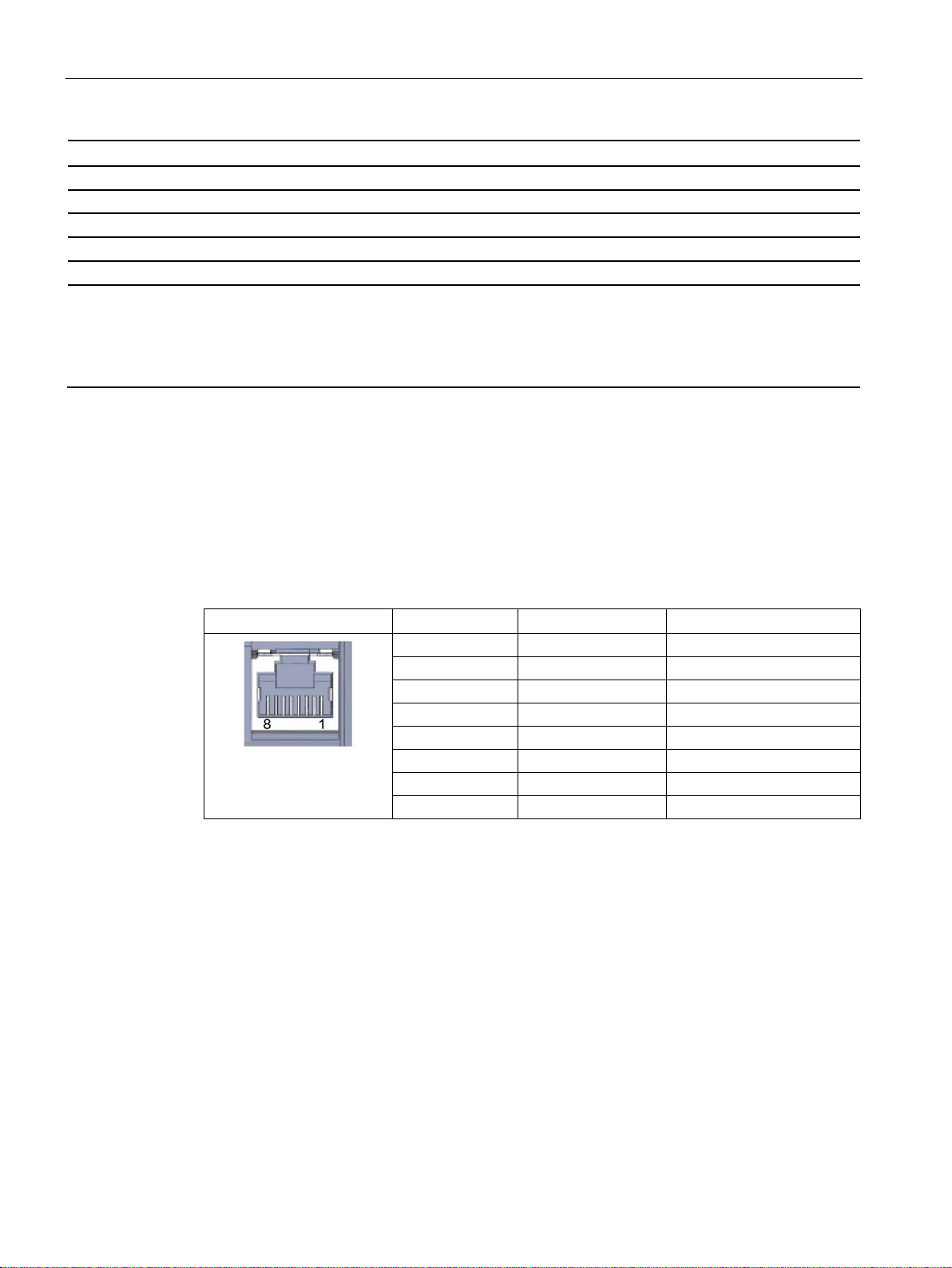
Technical specifications
Technical specifications - CloudConnect 712
Design, dimensions and weight
Module format
Compact module S7-1500
Degree of protection
IP20
Weight
300 g
Dimensions (W x H x D)
35 x 147 x 127 mm
View of the RJ-45 jack
Pin
Signal name
Assignment
1
D1+
D1+ bidirectional
2
D1-
D1- bidirectional
3
D2+
D2+ bidirectional
4
D3+
D3+ bidirectional
5
D3-
D3- bidirectional
6
D2-
D2- bidirectional
7
D4+
D4+ bidirectional
8
D4-
D4- bidirectional
6.2 Pinout of the Ethernet interfaces
Mounting type
• 35 mm DIN rail mounting
• S7-300 standard rail mounting
• S7-1500 standard rail mounting
• Wall mounting
For further data, refer to section Application and functions (Page 11).
6.2 Pinout of the Ethernet interfaces
Pinout of the gigabit Ethernet interfaces
The table below shows the pin assignment of the two interfaces P1 and P2.
SIMATIC CC712
100 Operating Instructions, 05/2019, C79000-G8976-C503-01
 Loading...