

Page 1
Preface, Contents
User Information
SIMATIC
C7-621 / C7-621 AS-i
Control Systems
Volume 1
Hardware and Installation
Manual
Product Overview
Installation
Installing and Preparing
the C7
Configuring an MPI Network
Connecting a Programming
Device / PC to a C7
AS-i
Attaching a C7-621 AS-i
I/Os
C7-621 Digital I/Os
1
2
3
4
5
6
C79000-G7076-C621-01
C7-621 Analog I/Os
Maintenance
Appendix
General Technical Specifications
Guidelines for Handling ESD
Devices
Safety of Electronic Controllers
SIMATIC C7 and S7 Refer-
ences
Glossary, Index
7
8
A
B
C
D
Page 2
Safety Guidelines
!
!
!
This manual contains notices which you should observe to ensure your own personal safety, as well as to
protect the product and connected equipment. These notices are highlighted in the manual by a warning
triangle and are marked as follows according to the level of danger:
Danger
indicates that death, severe personal injury or substantial property damage will result if proper precautions are
not taken.
Warning
indicates that death, severe personal injury or substantial property damage can result if proper precautions are
not taken.
Caution
indicates that minor personal injury or property damage can result if proper precautions are not taken.
Note
draws your attention to particularly important information on the product, handling the product, or to a particular
part of the documentation.
Qualified Personnel
Correct Usage
The device/system may only be set up and operated in conjunction with this manual.
Only qualified personnel should be allowed to install and work on this equipment. Qualified persons are
defined as persons who are authorized to commission, to ground, and to tag circuits, equipment, and systems in accordance with established safety practices and standards.
Note the following:
Warning
!
Trademarks
The reproduction, transmission or use of this document or its contents is
not permitted without express written authority. Of fenders will be liable for
damages. All rights, including rights created by patent grant or registration
of a utility model or design, are reserved.
Siemens AG
Bereich Automatisierungstechnik
Industrial Automation Systems
Postfach 4848, D-90327 Nuernberg
This device and its components may only be used for the applications described in the catalog or the technical
description, and only in connection with devices or components from other manufacturers which have been
approved or recommended by Siemens.
This product can only function correctly and safely if it is transported, stored, set up, and installed correctly, and
operated and maintained as recommended.
SIMATICR and SMATIC NETR are registered trademarks of SIEMENS AG.
Third parties using for their own purposes any other names in this document which refer to
trademarks might infringe upon the rights of the trademark owners.
Disclaimer of LiabilityCopyright E Siemens AG 1997 All rights reserved
We have checked the contents of this manual for agreement with the
hardware and software described. Since deviations cannot be precluded
entirely, we cannot guarantee full agreement. However, the data in this
manual are reviewed regularly and any necessary corrections included in
subsequent editions. Suggestions for improvement are welcomed.
Subject to change without prior notice.
E Siemens AG 1997
Siemens Aktiengesellschaft C79000-G7076-C621
C7-621 / C7-621 AS-i Control Systems
Page 3

Preface
Purpose
Audience
Contents of the
Manual
This manual will help you with the following tasks:
S Installing and wiring up a C7-621 or C7-621 AS-i (Volume 1)
S Assigning parameters to the CPU of the C7-621 or C7-621 AS-i,
downloading a user program to the CPU, and starting up
(Volume 2)
S Making the settings required on the C7-621 and C7-621 AS-i for
operation and using the operator interface functions
(Volume 2)
This manual is intended for two different groups of readers:
S Volume 1:
Users installing the C7 mechanically and electrically on site and
preparing the C7 so that it is ready for operation.
S Volume 2:
Users creating control programs and operator interface configurations and
downloading them to the C7.
This manual describes the hardware and software of the
C7-621 and C7-621 AS-i. It consists of two volumes.
Volume 1 of the manual deals with the following topics:
S Installing and preparing the C7-621 or C7-621 AS-i
S Networking the C7-621 or C7-621 AS-i with a programming device and
other devices
S Connecting the digital and analog I/Os
S Connecting the IM 621 interface module
C7-621 / C7-621 AS-i Control Systems
C79000-G7076-C621-01
iii
Page 4
Preface
Volume 2 of the manual deals with the following topics:
S Startup of the C7
S Controlling with the C7 CPU
S Addressing and assigning parameters for the C7 I/Os
S C7 diagnostics
S AS-i system concept
S Using and operating AS-i
S Using the operator interface functions of the C7
Conventions for
C7
Scope of the
Manual
C7 Manual
Other Manuals
Required
T o make the manual easier to read, the device types C7-621 or C7-621 AS-i
will simply by called C7 in the manual.
If the device is simply called C7 in the manual, the information applies to
both versions of the control system. Where differences occur, the full name
of the unit will be used.
This manual is valid for the following C7s:
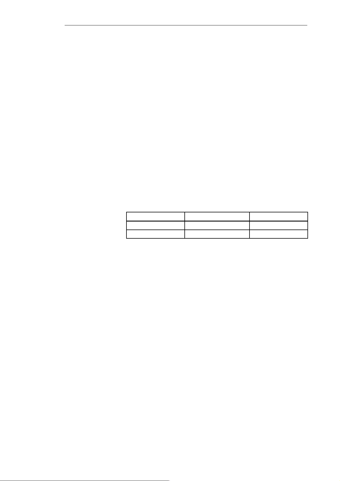
C7 Order Number Versions and Higher
C7-621 6ES7621-1AD00-0AE3 01
C7-621 AS-i 6ES7621-6BD00-0AE3 01
This manual can be obtained under the order number
6ES7621-1AD00-8BA0.
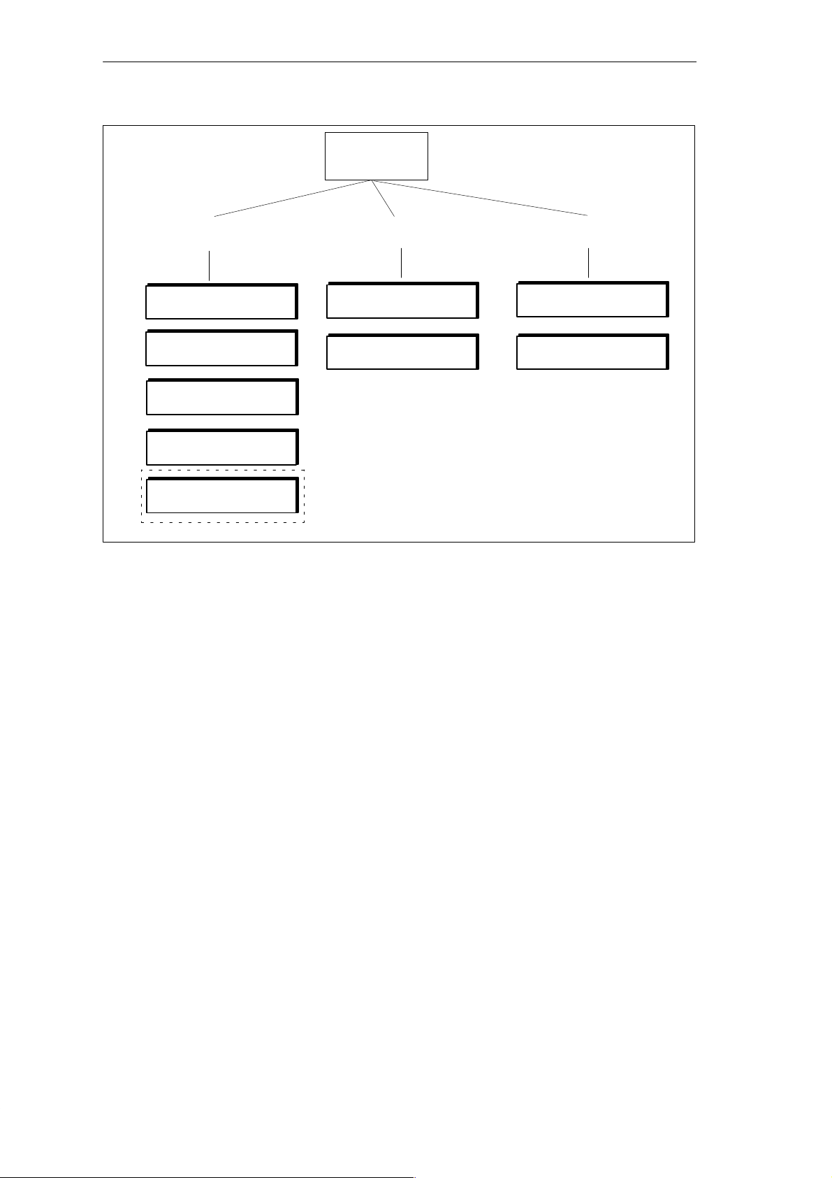
This manual describes the C7-621 and C7-621 AS-i. T o program, expand and
configure a C7, you also require the following manuals:
iv
C7-621 / C7-621 AS-i Control Systems
C79000-G7076-C621-01
Page 5
C7
Preface
Programming
Assigning Parameters
STL for S7-300/400
LAD for S7-300/400
System and Standard
Functions
STEP7 User Manual
C7-621 AS-i
Brochure
Program Design
ConfiguringExpanding
Harware and Installation
Module Specifications
If required
T o familiarize yourself with the AS-i system, we recommend the following
procedure:
ProTool/ Lite
ProTool
S You should certainly read the AS-i brochure.
This brochure can be ordered from all Siemens offices.
C7-621 / C7-621 AS-i Control Systems
C79000-G7076-C621-01
Actuator Sensor Interface
Order number E20001-P285-A497-V2-X-7600
v
Page 6
Preface
Table 1-1 STEP 7 Documentation Package, Order Number 6ES7810-4AA00-8AA0
Manual
Standard Software for S7 and
M7
STEP 7 User Manual
Manual:
STL for S7-300/400,
Programming
or
Manual:
LAD for S7-300/400,
Programming
This provides information about working with the STEP 7 tools.
S Installation and startup of STEP 7 on a PC/programming device
S Using the tools:
– Managing projects and files
– Configuring the S7-300 and assigning parameters
– Assigning symbolic names for user programs
– Creating and debugging user programs in STL/LAD
– Creating data blocks
– Configuring communication between CPUs
– Downloading, saving, and deleting user programs on CPUs and
programming devices
– Monitoring and modifying user programs (for example variables)
– Monitoring and modifying the CPU (for example mode, memory reset,
compress memory, protection levels)
Reference manuals for programming with STL or LAD:
S Basics of working with STL/LAD (for example structure of STL/LAD,
numerical formats, syntax)
S Description of all instructions in STEP 7 (with program examples)
S Description of the various ways of addressing in STEP 7 (with examples)
S Description of all integrated functions on the CPUs
Topics
S Description of the CPU-internal registers
Reference Manual:
System Software for S7-300
and S7-400, System and
Standard Functions
User Manual:
Standard Software for S7,
Converting S5 Programs
Detailed description of:
S All the standard functions (FCs) integrated in STEP 7
S All the system functions (SFCs) integrated in the operating system of the CPU
This manual provides information about converting STEP 5 programs to STEP 7:
S Working with the S5/S7 converter
S Rules for conversion
S Using converted STEP 5 standard function blocks in STEP 7
Manual: General Index General index of all the manuals in the documentation package.
vi
C7-621 / C7-621 AS-i Control Systems
C79000-G7076-C621-01
Page 7
Preface
Further
Information
Table 1-2 Further Manuals
Manual Topics
Programming Manual:
System Software for S7-300 and
S7-400, Program Design
Manual:
S7-300 Programmable
Controller, Har dware and
Installation
Reference Manual:
Programmable Contr ollers
S7-300, M7-300,
Module Data
Instruction List:
S7-300 Programmable
Controller, CPU
312/314/315/315-DP
Appendix D of Volume 2 of this manual contains a list with further sources of
information about the S7-300 and programmable logic controllers.
This manual contains basic information about designing STEP 7 programs:
S Introduction to the efficient solution of programming tasks using a
PC/programming device and STEP 7
S How the CPUs function (for example memory concept, access to inputs
and outputs, addressing, blocks, data types, data management)
S Description of STEP 7 data management
S Using data types of STEP 7
S Using linear and structured programming (with program examples)
S Using block call instructions
S Overview of using STEP 7 tools for developing projects (with an
extensive example)
S Using test and diagnostic functions of the CPUs in user programs (for
example error OBs, status word)
This manual describes the hardware of the S7-300:
S Configuring the S7-300
S Installing the S7-300
S Wiring and preparing the S7-300 for startup
S Properties and technical data of the S7-300 modules
This manual describes the hardware of the S7-300 modules:
S Analog modules
S Digital modules
S Interface modules
S Properties and technical data of the S7-300 modules
This describes the set of instructions of the CPU 312, CPU 314, CPU 315,
and CPU 315-DP including the run times of all instructions.
C7-621 / C7-621 AS-i Control Systems
C79000-G7076-C621-01
vii
Page 8
Preface
Table 1-2 Further Manuals, continued
Manual Topics
PG 7xx Descriptions of the PG hardware:
S Configuration and startup of the PG
S Possible expansions
S Configuration
S Trouble shooting
SIMATIC HMI
ProTool/ Lite
Manual for creating configurations:
S Working with ProTool/Lite
S Configuration
S Displays and messages
S Downloading a configuration to the C7
SIMATIC HMI
ProTool
Manual for creating configurations:
S Working with ProTool
S Configuration
S Displays and messages
S Downloading configurations to the C7
Finding Y our Way
Round the Manual
Standards
Questions
T o help you find specific information, the manual is laid out as follows:
S At the start of both volumes of the manual, you will find a complete table
of contents.
S In the left margin of the chapters, there is a subtitle indicating the content
of the section.
S After the appendix, there is a glossary listing important terminology used
in the manual.
S At the end of the manual there is a detailed subject index.
The C7 control system complies with the standards described in Appendix
A.1.
If you have questions about the C7 control system, please contact your
Siemens representative.
There is a list with the addresses of Siemens representatives world-wide in
Appendix E of Volume 2 of the manual.
If you have questions or comments about the manual itself, please complete
and return the remarks form. You will find this at the end of Volume 2.
viii
C7-621 / C7-621 AS-i Control Systems
C79000-G7076-C621-01
Page 9

Contents
1 Product Overview 1-1. . . . . . . . . . . . . . . . . . . . . . . . . . . . . . . . . . . . . . . . . . . . . . . . . . . . . . .
2 Installing and Preparing the C7 2-1. . . . . . . . . . . . . . . . . . . . . . . . . . . . . . . . . . . . . . . . . . .
2.1 Components and Accessories of the C7 2-2. . . . . . . . . . . . . . . . . . . . . . . . . . . .
2.2 Installing a C7 2-3. . . . . . . . . . . . . . . . . . . . . . . . . . . . . . . . . . . . . . . . . . . . . . . . . . .
2.3 Location of the C7 2-6. . . . . . . . . . . . . . . . . . . . . . . . . . . . . . . . . . . . . . . . . . . . . . . .
2.4 Electrical Installation and Pinouts 2-7. . . . . . . . . . . . . . . . . . . . . . . . . . . . . . . . . .
2.5 Guidelines for Trouble-Free Installation 2-13. . . . . . . . . . . . . . . . . . . . . . . . . . . . .
2.6 Connecting Up Cables 2-15. . . . . . . . . . . . . . . . . . . . . . . . . . . . . . . . . . . . . . . . . . . .
2.7 Connector Key Inserts 2-16. . . . . . . . . . . . . . . . . . . . . . . . . . . . . . . . . . . . . . . . . . . .
2.8 Contrast 2-17. . . . . . . . . . . . . . . . . . . . . . . . . . . . . . . . . . . . . . . . . . . . . . . . . . . . . . . .
2.9 I/O Expansion with the IM 621 2-18. . . . . . . . . . . . . . . . . . . . . . . . . . . . . . . . . . . . .
2.10 Memory Reset on the C7 2-20. . . . . . . . . . . . . . . . . . . . . . . . . . . . . . . . . . . . . . . . . .
2.11 Status and Error LEDs on the C7 2-23. . . . . . . . . . . . . . . . . . . . . . . . . . . . . . . . . . .
2.12 Clocks on the C7 2-24. . . . . . . . . . . . . . . . . . . . . . . . . . . . . . . . . . . . . . . . . . . . . . . . .
3 Configuring an MPI Network 3-1. . . . . . . . . . . . . . . . . . . . . . . . . . . . . . . . . . . . . . . . . . . . .
3.1 Communication via the MPI Interface 3-2. . . . . . . . . . . . . . . . . . . . . . . . . . . . . . .
3.2 Rules for Configuring an MPI Network 3-4. . . . . . . . . . . . . . . . . . . . . . . . . . . . . .
3.3 Cable Lengths 3-8. . . . . . . . . . . . . . . . . . . . . . . . . . . . . . . . . . . . . . . . . . . . . . . . . . .
3.4 Network Components 3-10. . . . . . . . . . . . . . . . . . . . . . . . . . . . . . . . . . . . . . . . . . . . .
3.5 Bus Connectors 3-12. . . . . . . . . . . . . . . . . . . . . . . . . . . . . . . . . . . . . . . . . . . . . . . . . .
3.5.1 PROFIBUS Bus Connector 3-13. . . . . . . . . . . . . . . . . . . . . . . . . . . . . . . . . . . . . . . .
3.5.2 Bus Connector 6ES7 972-0B.20-0XA0 3-14. . . . . . . . . . . . . . . . . . . . . . . . . . . . . .
3.5.3 Bus Connector 6ES7 972-0B.10-0XA0 3-17. . . . . . . . . . . . . . . . . . . . . . . . . . . . . .
3.5.4 Connecting the Bus Connector to a Module 3-19. . . . . . . . . . . . . . . . . . . . . . . . .
4 Connecting a Programming Device / PC to a C7 4-1. . . . . . . . . . . . . . . . . . . . . . . . . .
4.1 Connecting a Programming Device / PC to a C7 4-2. . . . . . . . . . . . . . . . . . . . .
4.2 Connecting a Programming Device/PC to Several Nodes 4-3. . . . . . . . . . . . .
5 Attaching a C7-621 AS-i 5-1. . . . . . . . . . . . . . . . . . . . . . . . . . . . . . . . . . . . . . . . . . . . . . . . . .
5.1 AS-i Attachments 5-2. . . . . . . . . . . . . . . . . . . . . . . . . . . . . . . . . . . . . . . . . . . . . . . .
5.2 The AS-i Cable 5-3. . . . . . . . . . . . . . . . . . . . . . . . . . . . . . . . . . . . . . . . . . . . . . . . . .
C7-621 / C7-621 AS-i Control Systems
C79000-G7076-C621-01
ix
Page 10

Contents
6 C7-621 Digital I/Os 6-1. . . . . . . . . . . . . . . . . . . . . . . . . . . . . . . . . . . . . . . . . . . . . . . . . . . . . . .
6.1 Digital Inputs 6-2. . . . . . . . . . . . . . . . . . . . . . . . . . . . . . . . . . . . . . . . . . . . . . . . . . . .
6.2 Digital Outputs 6-4. . . . . . . . . . . . . . . . . . . . . . . . . . . . . . . . . . . . . . . . . . . . . . . . . . .
6.3 Status Displays of the DI/DO 6-7. . . . . . . . . . . . . . . . . . . . . . . . . . . . . . . . . . . . . .
7 C7-621 Analog I/Os 7-1. . . . . . . . . . . . . . . . . . . . . . . . . . . . . . . . . . . . . . . . . . . . . . . . . . . . . .
7.1 Connecting Sensors to Analog Inputs 7-2. . . . . . . . . . . . . . . . . . . . . . . . . . . . . . .
7.1.1 Connecting Voltage and Current Sensors 7-5. . . . . . . . . . . . . . . . . . . . . . . . . . .
7.2 Connecting Loads/Actuators to the Analog Output 7-7. . . . . . . . . . . . . . . . . . . .
7.3 Analog Input 7-10. . . . . . . . . . . . . . . . . . . . . . . . . . . . . . . . . . . . . . . . . . . . . . . . . . . . .
7.3.1 Properties and Technical Data of the Analog Input Module 7-11. . . . . . . . . . . . .
7.4 Analog Output 7-15. . . . . . . . . . . . . . . . . . . . . . . . . . . . . . . . . . . . . . . . . . . . . . . . . . .
8 Maintenance 8-1. . . . . . . . . . . . . . . . . . . . . . . . . . . . . . . . . . . . . . . . . . . . . . . . . . . . . . . . . . . .
A General Technical Specifications A-1. . . . . . . . . . . . . . . . . . . . . . . . . . . . . . . . . . . . . . . . .
A.1 Technical Specifications A-2. . . . . . . . . . . . . . . . . . . . . . . . . . . . . . . . . . . . . . . . . . .
A.2 Notes on the CE Approval A-5. . . . . . . . . . . . . . . . . . . . . . . . . . . . . . . . . . . . . . . . .
A.3 Notes for Manufacturers of Machines A-7. . . . . . . . . . . . . . . . . . . . . . . . . . . . . . .
B Guidelines for Handling Electrostatically Sensitive Devices (ESD) B-1. . . . . . . . . .
B.1 What is ESD? B-2. . . . . . . . . . . . . . . . . . . . . . . . . . . . . . . . . . . . . . . . . . . . . . . . . . .
B.2 Electrostatic Charging of Objects and Persons B-3. . . . . . . . . . . . . . . . . . . . . . .
B.3 General Protective Measures Against Electrostatic Discharge Damage B-4.
B.4 Taking Measurements and Working on ESD Modules B-6. . . . . . . . . . . . . . . . .
B.5 Packing Electrostatic Sensitive Devices B-7. . . . . . . . . . . . . . . . . . . . . . . . . . . . .
C Safety of Electronic Controllers C-1. . . . . . . . . . . . . . . . . . . . . . . . . . . . . . . . . . . . . . . . . .
D SIMATIC C7 and S7 References D-1. . . . . . . . . . . . . . . . . . . . . . . . . . . . . . . . . . . . . . . . . . .
Glossary Glossary-1. . . . . . . . . . . . . . . . . . . . . . . . . . . . . . . . . . . . . . . . . . . . . . . . . . . . . . . . . .
Index Index-1. . . . . . . . . . . . . . . . . . . . . . . . . . . . . . . . . . . . . . . . . . . . . . . . . . . . . . . . . . . . . . . .
x
C7-621 / C7-621 AS-i Control Systems
C79000-G7076-C621-01
Page 11

Product Overview
1
In This Chapter
Accessories for
Installing and
Starting Up
a C7
This chapter introduces you to the C7-621 and C7-621 AS-i. A brief
overview of the range of performance will give you a first impression of the
two devices.
This chapter also explains the additional components that you can connect to
a C7.
T o install and start up the C7, you require the following accessories:
S Programming device or PC with an MPI interface and PG cable
S The following software must be loaded on the programming device or PC
– STEP 7 Tools
– ProTool or ProTool/Lite
C7-621 / C7-621 AS-i Control Systems
C79000-G7076-C621-01
1-1
Page 12
Product Overview
Overview
C7-621
There are two versions of the C7:
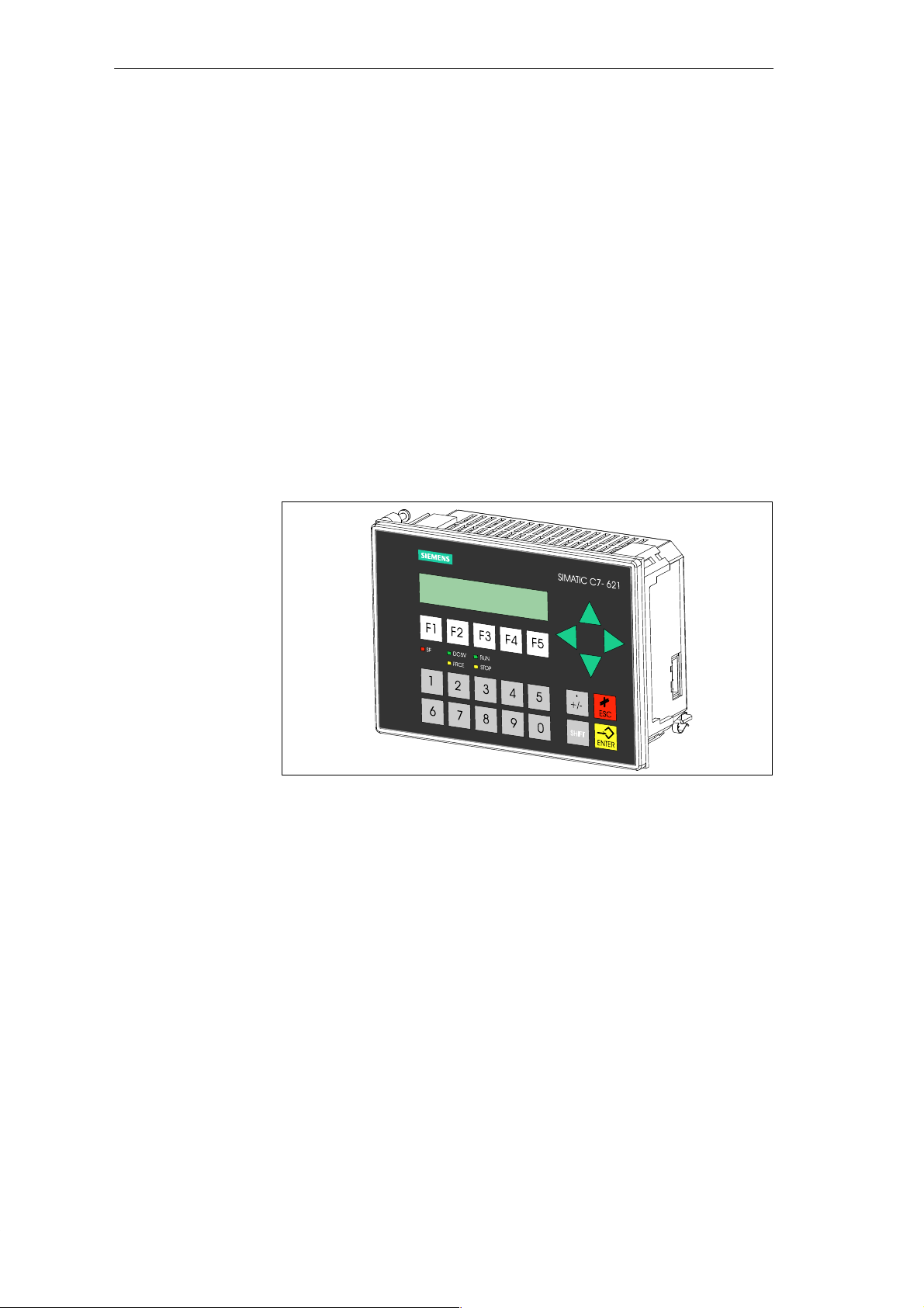
With a two-line display and 20 characters per line with 5 mm high characters
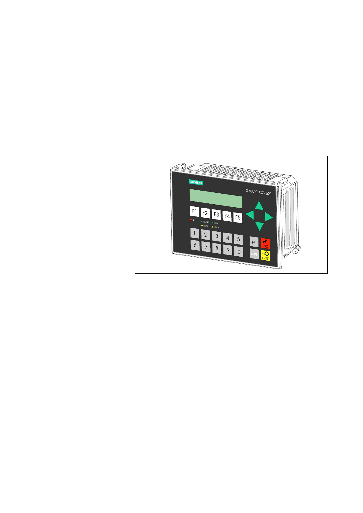
(see Figure 1-1).
The C7-621 has the following components:
S MPI interface
S Digital inputs and outputs
S Analog inputs and outputs
S P bus connection (for the IM 621 module)
Range of
Functions
1-2
Figure 1-1 C7-621
You can do the following with the C7-621:
S Run user programs that were written in STL, LAD or FBD and
downloaded to the C7 CPU.
S Process digital and analog signals using the I/Os integrated on the C7.
S Download and use operator interface applications that you created with
the “ProT ool” or “ProTool/Lite” configuration tool.
S Using these configurations, you can monitor and intervene in the process
you are controlling with the user program.
S Connect further S7-300 modules.
C7-621 / C7-621 AS-i Control Systems
C79000-G7076-C621-01
Page 13
Product Overview
C7-621 Units
C7-621 AS-i
The C7 has two independent units that communicate with each other via an
internal MPI interface:
S C7 CPU with digital and analog inputs and outputs
S C7 OP
Where necessary, these units are dealt with separately in the manuals.
With a two-line display and 20 characters per line with characters 5 mm high
(see Figure 1-2).
The C7-621 AS-i has the following components:
S MPI interface
S AS-interface
S P bus connection (for the IM 621 module)
This model does not have digital inputs/outputs and analog inputs/outputs.
Figure 1-2 C7-621 AS-i
Range of
Functions
You can do the following with the C7-621 AS-i control system:
S Run user programs that were written in STL, LAD or FBD and
downloaded to the C7 CPU.
S Connect actuators and sensors via the AS-interface to the C7-621 AS-i.
S Download and use operator interface applications that you created with
the “ProT ool” or “ProTool/Lite” configuration tool.
S Using these configurations, you can monitor and intervene in the process
you are controlling with the user program.
S Connect further S7-300 modules.
C7-621 / C7-621 AS-i Control Systems
C79000-G7076-C621-01
1-3
Page 14

Product Overview
C7-621 AS-i Units
The C7 has two independent units that communicate with each other via an
internal MPI interface.
S C7 CPU with C7 AS-i CP
S C7 OP
When necessary, these units are dealt with separately in the manuals.
1-4
C7-621 / C7-621 AS-i Control Systems
C79000-G7076-C621-01
Page 15
Product Overview
Components that
Can Be Connected
to a C7
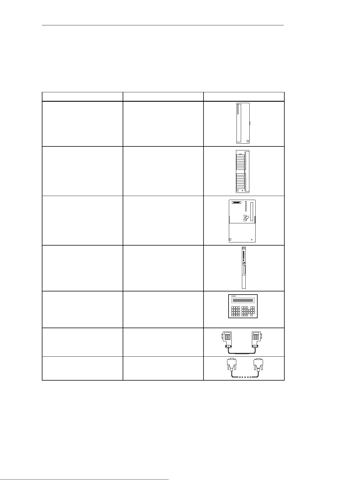
Table 1-1 Components that Can Be Connected to a C7
Component Function Schematic
IM 621 interface module with
cable
Apart from the connections to the process you can also connect various
components to the C7. The most important components and their functions
are listed in T able 1-1:
...connects a C7 with an
expansion rack for S7-300
modules
Signal module (SM)
(Digital input modules,
digital output modules,
analog input modules,
...adapt various process signal
levels to the C7 CPU. Can be
connected to the C7 via an IM
621.
analog output modules,
analog input/output modules)
S7-300 (CPU) ...communicates via the MPI
interface with C7 and with other
nodes on an MPI network.
S7-400 (CPU) ...communicates via the MPI
interface with C7 and other
nodes on an MPI network.
OP (Operator Panel) ...allows operator interface
functions.
PROFIBUS LAN cable with
bus connector
...interconnects nodes on an
MPI network.
PG cable ...connects a programming
device/PC with a C7.
C7-621 / C7-621 AS-i Control Systems
C79000-G7076-C621-01
1-5
Page 16
Product Overview
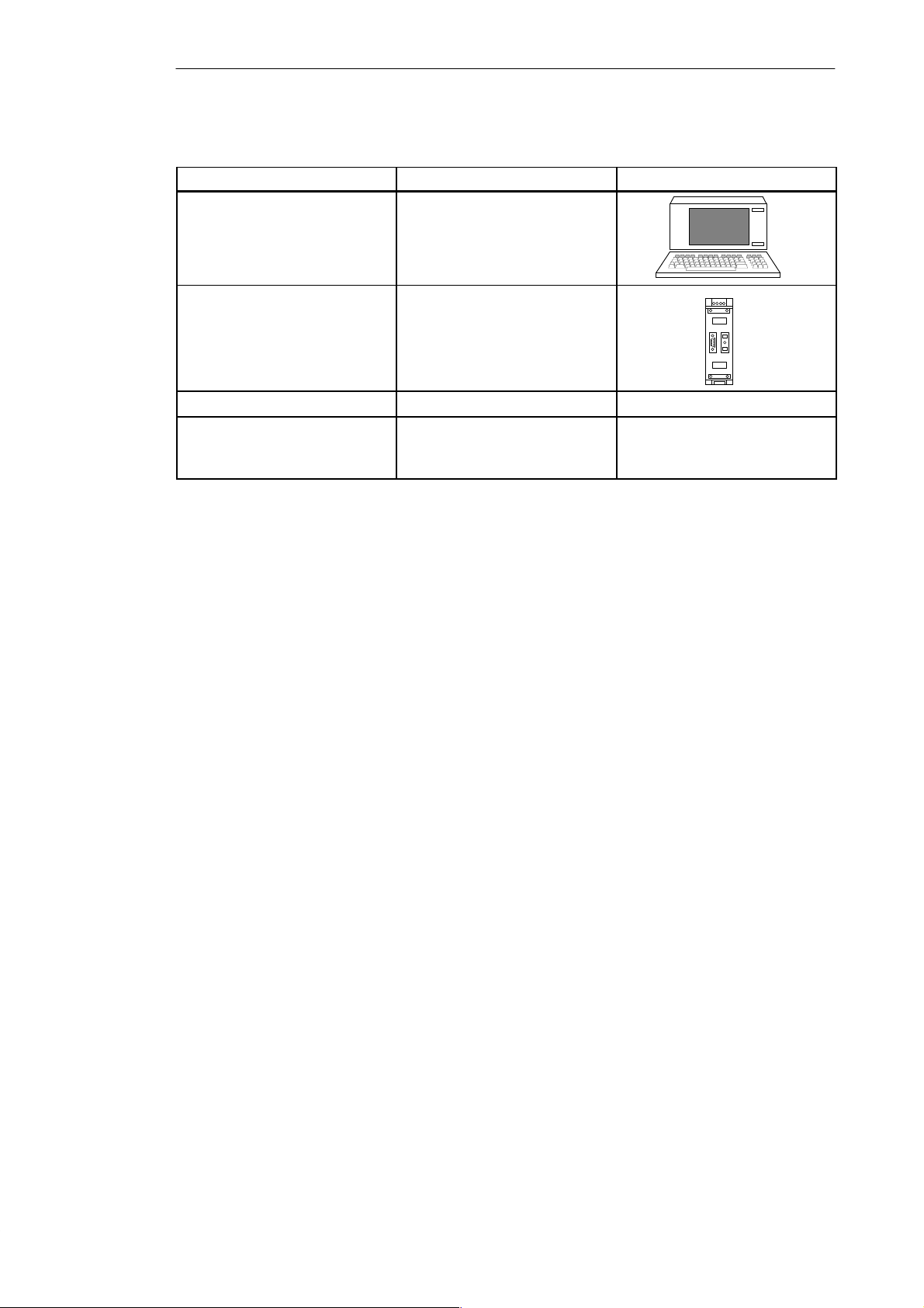
Table 1-1 Components that Can Be Connected to a C7, continued
Component SchematicFunction
Programming device (PG) or PC
with the STEP 7 software
package and ProT ool or Pro
...configures, assigns
parameters, programs, and tests
the C7.
T ool/Lite
RS 485 repeater ...amplifies the signals in an
MPI or PROFIBUS DP network
and connects segments of an
MPI or PROFIBUS DP network.
Sensors and actuators
AS-i slaves Refer to the various catalogs
(applies only to the C7-621
AS-i).
1-6
C7-621 / C7-621 AS-i Control Systems
C79000-G7076-C621-01
Page 17
Product Overview
Overview of the C7
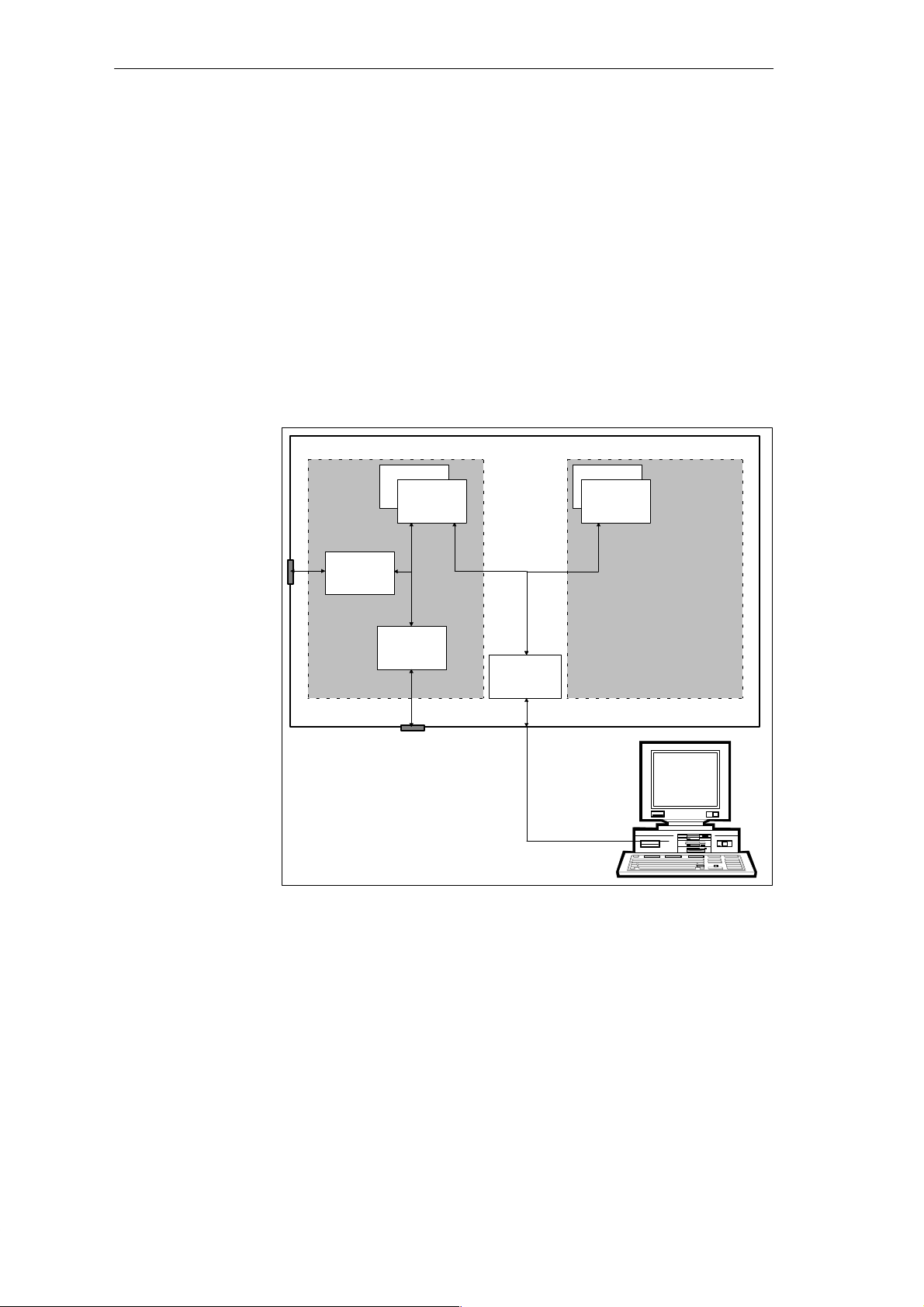
The SIMATIC C7-621/C7-621 AS-i devices consist of several components
that interact with each other:
S A programmable controller CPU of the SIMATIC S7-300 class (C7 CPU),
S A line-oriented SIMATIC OP (C7 OP),
S Integrated digital and analog I/Os (C7-621 I/Os),
S A P bus connection for expanding the C7-621 with an IM 621 using
S7-300 modules,
S An MPI interface for communication with the programming device/PC
and other S7 CPUs, C7 control systems and OPs,
S An AS-interface (AS-i) for connecting sensors and actuators (version
C7-621 AS-i, see Figure 1-4)
C7-621
C7 CPU C7 OP
I/Os
CPU memory
C7 CPU
C7
OP memory
C7 OP
P bus
MPI
interface
STEP 7
ProTool Lite
or
ProTool
Figure 1-3 Components of the C7-621
The individual components integrated in the SIMATIC C7 correspond to the
components that can also be used in the modular configuration consisting of
an S7-300 CPU, OP etc. The I/O expansion via the P bus interface (IM 621)
allows the connection of a maximum of four SIMATIC S7-300 modules. The
AS-interface allows the connection of sensors and actuators to the C7-621
AS-i (Figure 1-4).
C7-621 / C7-621 AS-i Control Systems
C79000-G7076-C621-01
1-7
Page 18
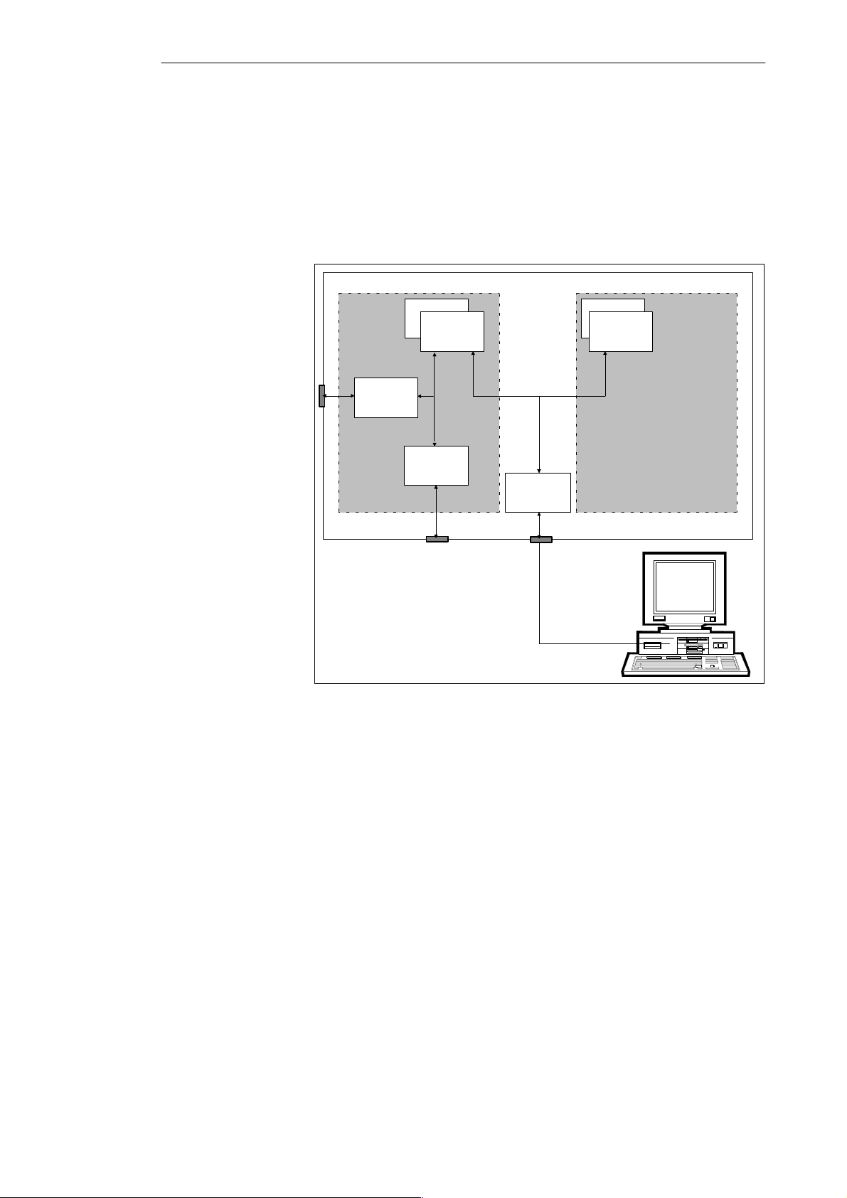
Product Overview
The basic functions also correspond to those of a modular configuration with
standard modules from the programmable controller and OP families, the
individual components operate independently of each other and each of the
processors has its own memory.
C7 CPU is programmed with STEP 7 and the C7 OP is configured with
ProT ool/Lite.
C7-621 AS-i
C7 CPU C7 OP
C7-AS-i
CPU memory
C7 CPU
P-Bus
MPI
interface
OP memory
C7 OP
Figure 1-4 Components of the C7-621 AS-i
STEP 7
ProTool Lite
or
ProTool
1-8
C7-621 / C7-621 AS-i Control Systems
C79000-G7076-C621-01
Page 19
Installing and Preparing the C7
2
Chapter
Overview
Section Description Page
2.1 Components and Accessories of the C7 2-2
2.2 Installing a C7 2-3
2.3 Location of the C7 2-6
2.4 Electrical Installation and Pinouts 2-7
2.5 Guidelines for Trouble-Free Installation 2-13
2.6 Connecting Up Cables 2-15
2.7 Connector Key Inserts 2-16
2.8 Contrast 2-17
2.9 I/O Expansion with the IM 621 2-18
2.10 Memory Reset on the C7 2-20
2.11 Status and Error LEDs on the C7 2-23
2.12 Clocks on the C7 2-24
C7-621 / C7-621 AS-i Control Systems
C79000-G7076-C621-01
2-1
Page 20

Installing and Preparing the C7
2.1 Components and Accessories of the C7
Components
Supplied with the
C7-621
Components of the
C7-621 AS-i
Accessories
The following components are supplied with the C7-621:
S C7-621 (order number 6ES7 621-1AD00-0AE3)
S Grounding bar
S 6 shield clips
S Seal and 4 securing posts
S Set of connectors for C7 I/Os with key inserts
S Product information
The following components are supplied with the C7-621 AS-i:
S C7-621 AS-i (order number 6ES7 621-6BD00-0AE3)
S Seal and 4 securing posts
S Set of connectors for AS-i and C7 power supply with key inserts
S Product information
The following components can be ordered as accessories for the C7:
S Manual: C7-621, C7-621 AS-i Control Systems consisting of two volumes
in the following languages:
German: 6ES7 621-1AD00-8AA0
English: 6ES7 621-1AD00-8BA0
French: 6ES7 621-1AD00-8CA0
Italian: 6ES7 621-1AD00-8DA0
Spanish: 6ES7 621-1AD00-8EA0
2-2
S Service package (seal and 4 securing posts) 6ES7 623-1AE00-3AA0
S Set of connectors for C7 I/Os with key inserts
6ES7 623-1AE00-4AA0
S IM 621 interface module with cable 6ES7 621-1AD00-6AE3
C7-621 / C7-621 AS-i Control Systems
C79000-G7076-C621-01
Page 21
2.2 Installing a C7
Installing and Preparing the C7
The Installation
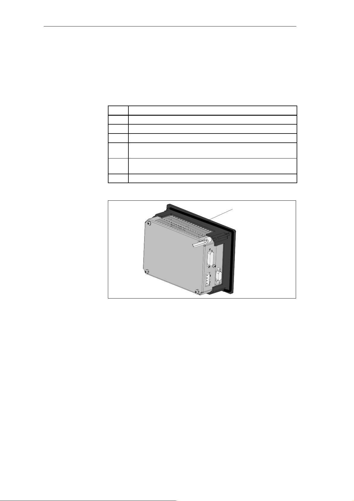
The C7 is designed for fixed installation in a switching panel or wiring closet
door. To install the C7, follow the steps outlined below:
Step Action
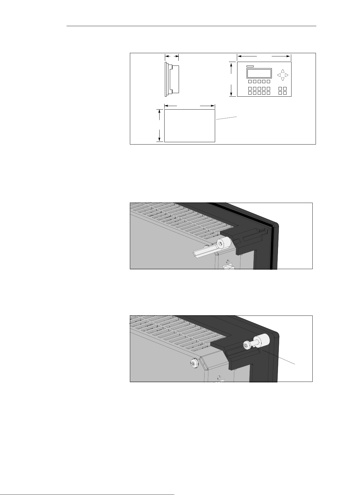
1. Cut out a section of the switching panel as shown in Figure 2-2.
2. Insert the sealing ring behind the front panel (see Figure 2-1).
3. Insert the C7 into the cutout in the switching panel.
4. Insert the 4 securing posts (see Figure 2-3) into the guides, pushing them
until the spring engages.
5. Screw the 4 securing screws supplied with the C7 into the 4 securing posts
(see Figure 2-4 ➀).
6. Tighten the 4 screws with a screwdriver (tightening torque 0.6 Nm).
Insert sealing ring here
Figure 2-1 Inserting the Sealing Ring
C7-621 / C7-621 AS-i Control Systems
C79000-G7076-C621-01
2-3
Page 22
Installing and Preparing the C7
Figure 2-2 Dimension Drawings for the C7
Securing Post
Before Engaging
110
16868
120
159+0,5
Cutout in front panel
+0,5
Securing Post
Engaged
2-4
Figure 2-3 Securing Post Before Engaging
Figure 2-4 Securing Post Engaged, with Screw
➀
C7-621 / C7-621 AS-i Control Systems
C79000-G7076-C621-01
Page 23
Installing and Preparing the C7
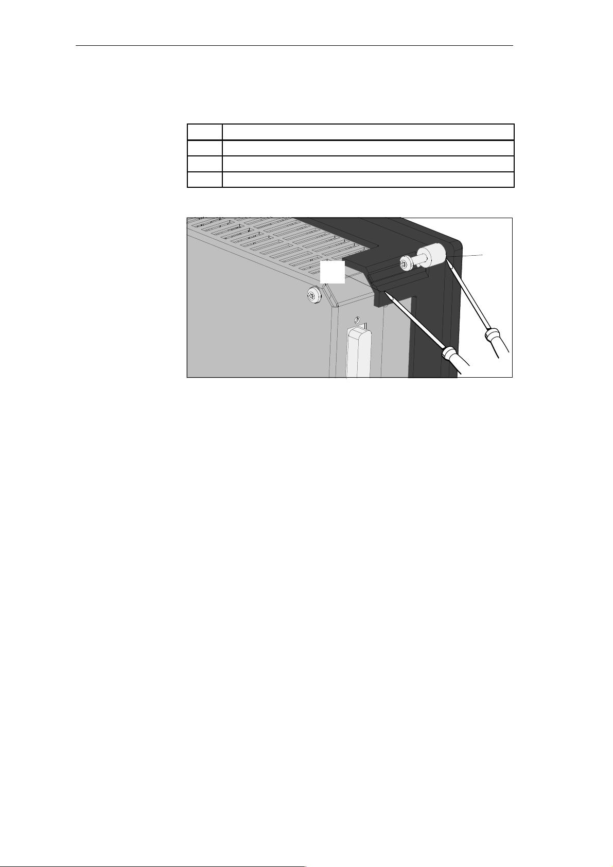
Releasing the
Securing Post
T o release a securing post, follow the steps outlined below:
Step Action
1. Loosen the screw.
2. Lever the securing post upwards (➀ in Figure 2-5).
3. Lever the securing post out of the guide (➁ in Figure 2-5).
➁
➀
Figure 2-5 Removing the Securing Post
C7-621 / C7-621 AS-i Control Systems
C79000-G7076-C621-01
2-5
Page 24

Installing and Preparing the C7
2.3 Location of the C7
Points to Note
When Installing
the C7
When installing the C7, please remember the following points:
S The thickness of the switching panel can be between 1 and 4 mm. Make
sure that the sealing ring makes a tight seal all round.
S There must be a clearance of at least 50 mm above and below and 70 mm
at the sides of the C7 as shown in Figure 2-6.
S Make sure that the sealing ring on the front panel sits correctly.
S Choose a location for the C7 away from direct sunlight.
50
70 70
50
Figure 2-6 Minimum Clearances when Installing the C7
2-6
C7-621 / C7-621 AS-i Control Systems
C79000-G7076-C621-01
Page 25
2.4 Electrical Installation and Pinouts
Installing and Preparing the C7
Overview
C7-621 and C7-621
AS-i
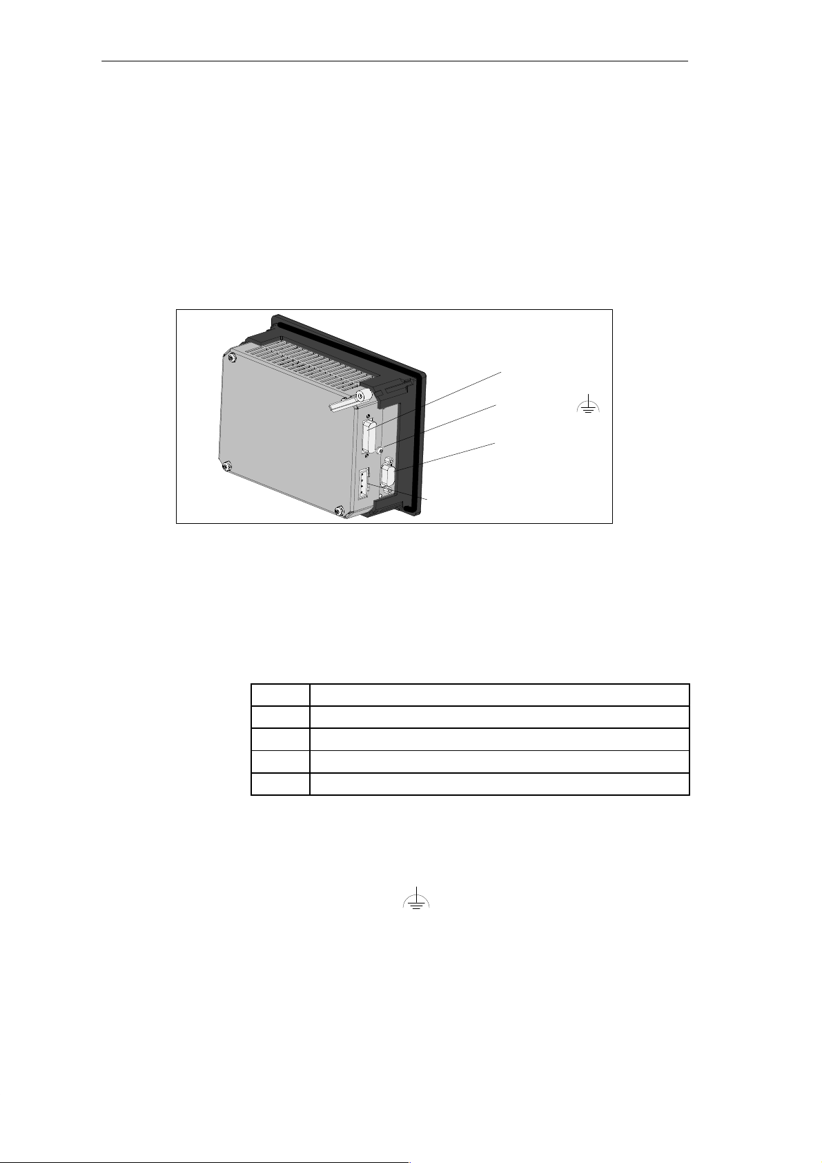
T o allow various components to be connected, the C7 is equipped with male
and female connectors.
Figure 2-7 illustrates the connection of the C7 power supply for a C7-621.
The pinouts of the connectors are shown in the following tables.
P bus (IM 621)
Functional
ground
MPI
Input 24 V DC
Figure 2-7 Power Supply Connectors for the C7-621
Input 24V DC
MPI
Functional Ground
P Bus (IM 621)
The pinout of the input 24V DC (C7 power supply) and DI/DO power supply
is shown below. The C7 CPU, C7 OP and digital/analog sections (C7-621)
are supplied with power.
Table 2-1 Pinout
Pin
L+ DC 24V
M (chassis M24V)
NC not connected
NC not connected
Function
Connector for MPI-compliant components.
Connect functional ground
(see Figure 2-7) to the closest available
point of the closet chassis using a cable lug and a cable with a minimum
cross-sectional area of 4 mm
2
.
T o connect an S7-300 expansion rack via an IM 621.
C7-621 / C7-621 AS-i Control Systems
C79000-G7076-C621-01
2-7
Page 26
Installing and Preparing the C7
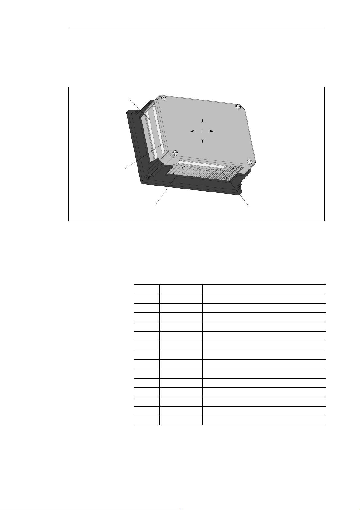
C7-621
Figure 2-8 illustrates the C7-621 with digital and analog connectors. These
connectors only exist on the C7-621. The pinouts of the connectors are
shown in the following tables.
Digital input (top)
left right
Digital output (bottom)
Analog input
Figure 2-8 View of a C7-621 with External I/O Ports
top
bottom
Analog output
Digital Input
Table 2-2 Pinout of the Digital Inputs
Pin
0.0 I124.0 Digital input 0
0.1 I124.1 Digital input 1
0.2 I124.2 Digital input 2
0.3 I124.3 Digital input 3
0.4 I124.4 Digital input 4
0.5 I124.5 Digital input 5
0.6 I124.6 Digital input 6
0.7 I124.7 Digital input 7
1.0 I125.0 Digital input 8
1.1 I125.1 Digital input 9
1.2 I125.2 Digital input 10
1.3 I125.3 Digital input 11
1.4 I125.4 Digital input 12
1.5 I125.5 Digital input 13
Signal Function
2-8
C7-621 / C7-621 AS-i Control Systems
C79000-G7076-C621-01
Page 27
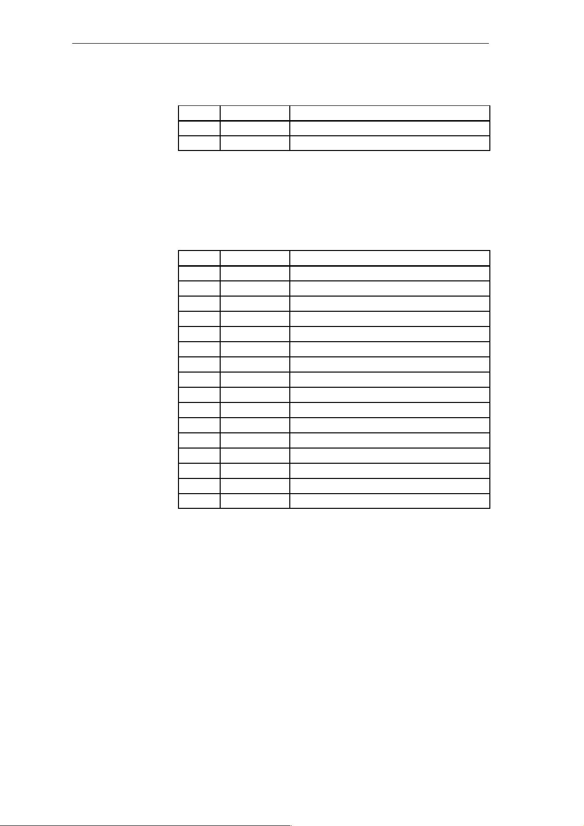
Digital Ouput
Installing and Preparing the C7
Table 2-2 Pinout of the Digital Inputs, continued
Pin FunctionSignal
1.6 I125.6 Digital input 14
1.7 I125.7 Digital input 15
Table 2-3 Pinout of the Digital Outputs
Pin Signal Function
0.0 Q124.0 Digital output 0
0.1 Q124.1 Digital output 1
0.2 Q124.2 Digital output 2
0.3 Q124.3 Digital output 3
0.4 Q124.4 Digital output 4
0.5 Q124.5 Digital output 5
0.6 Q124.6 Digital output 6
0.7 Q124.7 Digital output 7
1.0 Q125.0 Digital output 8
1.1 Q125.1 Digital output 9
1.2 Q125.2 Digital output 10
1.3 Q125.3 Digital output 11
1.4 Q125.4 Digital output 12
1.5 Q125.5 Digital output 13
1.6 Q125.6 Digital output 14
1.7 Q125.7 Digital output 15
C7-621 / C7-621 AS-i Control Systems
C79000-G7076-C621-01
2-9
Page 28
Installing and Preparing the C7
Analog Input/
Output
Table 2-4 Pinout of the Analog Inputs/Outputs
Pin
AI1-U Analog input 1, signal input for voltage
AI1-I Analog input 1, signal input for current
AI1-M Analog input 1, reference potential
AI2-U Analog input 2, signal input for voltage
AI2-I Analog input 2, signal input for current
AI2-M Analog input 2, reference potential
AI3-U Analog input 3, signal input for voltage
AI3-I Analog input 3, signal input for current
AI3-M Analog input 3, reference potential
AI4-U Analog input 4, signal input for voltage
AI4-I Analog input 4, signal input for current
AI4-M Analog input 4, reference potential
AO-U Analog output, signal output für voltage
AO-I Analog output, signal output für current
AO-M Analog output, reference potential
Function
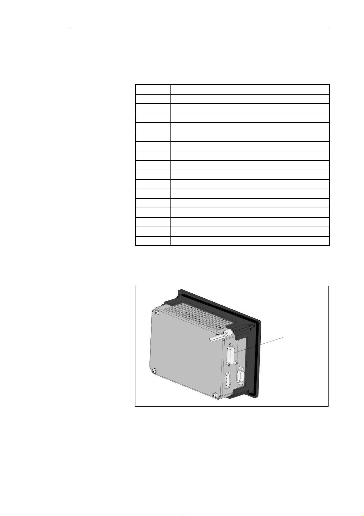
P Bus (IM 621)
P bus connector
(IM 621)
Figure 2-9 C7-621 with IM 621 Connector
2-10
C7-621 / C7-621 AS-i Control Systems
C79000-G7076-C621-01
Page 29
Installing and Preparing the C7
C7-621 AS-i
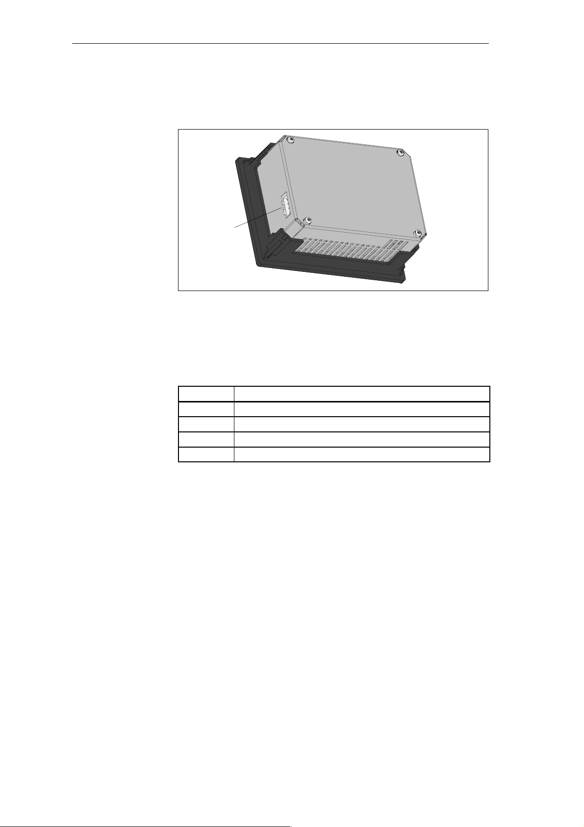
AS-i Connector
The figure illustrates the AS-i connector of the C7-621 AS-i. This connector
only exists on the C7-621 AS-i.
AS-i connector
Figure 2-10 C7-621 AS-i with AS-i Connector
T o connect actuators, sensors and the AS-i power supply unit
Table 2-5 Pinout of the AS-Interface
Pin
AS-i - Connected internally with AS-i AS-i + Connected internally with AS-i +
AS-i - Connected internally with AS-i AS-i + Connected internally with AS-i +
Function
C7-621 / C7-621 AS-i Control Systems
C79000-G7076-C621-01
2-11
Page 30
Installing and Preparing the C7
Device Connectors
of the C7
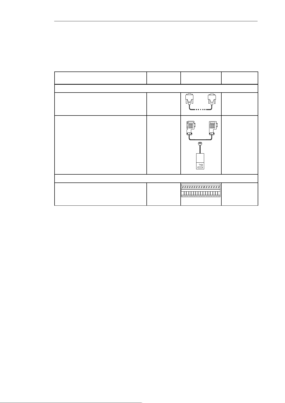
Table 2-6 Connecting Cables for the C7 Connectors
Connecting Cable Comments Schematic Connection
MPI Interface
PG cable - C7 PG
PROFIBUS LAN cable,
Interior cable,
Underground cable
and bus connector,
without PG interface,
with PG interface
and PROFIBUS bus terminal RS 485,
with 1.5 m, and 3 m cable,
with PG interface and 1.5 m cable.
Connectors for C7 I/Os
You can use the following connecting cables to connect the C7 to other
components:
The cable must
be assembled by
the user
Between ...
C7 S7-300
C7 S7-400
C7 OP
C7 PG
C7 C7
C7 S7-300
C7 S7-400
C7 OP
Connector for C7 I/Os
Conductor cross-section
16 pin
4 pin
0.2 to 2.5 mm
C7 external
sensor
2
2-12
C7-621 / C7-621 AS-i Control Systems
C79000-G7076-C621-01
Page 31

2.5 Guidelines for Trouble-Free Installation
Installing and Preparing the C7
Overview
Cabling Rules
Wiring Closet
Layout
T o prevent disturbances, the wiring and cabling in an automation system
must be installed according to certain rules.
If a system is poorly grounded or not shielded, low frequency and high
frequency interference signals can be coupled into the internal bus of the
controller and cause malfunctions.
Interference signals or noise can be caused for example by switching relays
or contactors (rapid changes in current or voltage levels, high frequency
interference signals) or by different ground potentials between two sections
of the system (low frequency interference signals).
Only shielded cables are permitted for data lines and analog signal lines.
S Cable shields must be grounded at both ends.
The standard cables in the catalogs ST80.1 and ST70 meet these
requirements.
S All plug-in connectors must be secured by screws or locked in position.
S Data lines and signal lines must not be laid parallel to power lines. Use a
separate cable duct for signal lines with a minimum clearance of 50 cm to
power lines.
Install devices that could introduce interference signals from the outside at
the bottom of the wiring closet The grounding rail should be located directly
at the point of entry to the closet so that cables that could be carrying
interference signals can be connected directly to ground. The shields of all
shielded cables must make contact here. If the signal lines have a double
shield, only the outer shield makes contact here.
Install long signal lines along the walls of the wiring closet. T o reduce
interference, it is important to plan the layout of the wiring closet in keeping
with the EMC guidelines. All the chassis connections in the wiring closet
must be established with large conductor cross-sections and contact should be
over a large an area as possible.
Analog devices installed in the wiring closet should be insulated and
grounded at one point in the closet (use copper band!).
Always use metal parts with the same electrical characteristics in the cabinet
(do not use aluminum due to the danger of oxidization).
C7-621 / C7-621 AS-i Control Systems
C79000-G7076-C621-01
2-13
Page 32

Installing and Preparing the C7
All the doors and metal panels (side, rear and top panels) of the wiring closet
should be connected at least three times to the closet frame (keep the
connections short and make sure that contact is over a large area with bare,
unpainted metal).
Note
If you use equipment that generates high electrostatic voltages (for example
textile machinery), the grounding cables of the machine parts producing high
voltage interference signals should be connected to a separate ground
(surface grounding with building construction, reinforcement) from the
grounding point of the wiring closet.
The manual /70/ contains installation guidelines and deals with measures for
protecting from interference.
Overvoltage
Protection
Measures to prevent overvoltage and lightning protection are described in the
guidelines in /70/ .
2-14
C7-621 / C7-621 AS-i Control Systems
C79000-G7076-C621-01
Page 33
2.6 Connecting Up Cables
Installing and Preparing the C7
Overview
Procedure
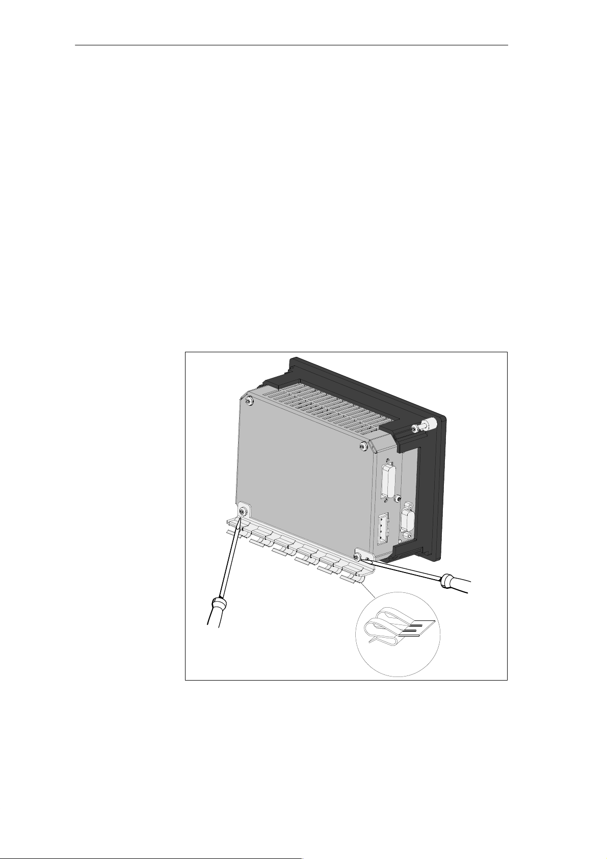
This chapter describes how to connect the shield of shielded signal cables
with ground. The shield is connected directly to the ground terminal of the
C7 via a grounding bar.
Fit the grounding bar and the shield clips supplied with the C7-621 as
follows:
1. Remove the two screws from the C7-621 as shown in Figure 2-11.
2. Position the grounding bar as shown in Figure 2-11 and fasten it in
position with the two screws previously removed.
3. Fit the shield clips on to the grounding bar as shown in
Figure 2-11.
4. Press the stripped cable into the shield clips so that the shield of the cable
makes the best possible contact.
Figure 2-11 C7-621 with Grounding Bar and Shield Clips
C7-621 / C7-621 AS-i Control Systems
C79000-G7076-C621-01
Shield clip
2-15
Page 34
Installing and Preparing the C7
2.7 Connector Key Inserts
Overview
Keying
Connectors
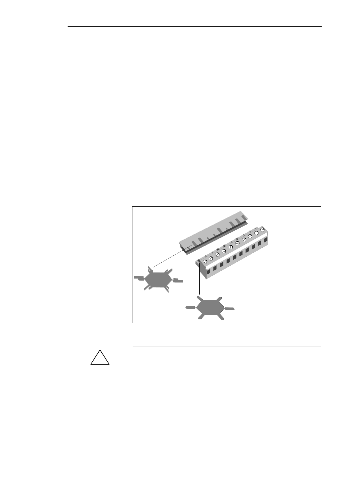
You can order a set of connectors with key inserts for a C7 (see Section 2.1,
Accessories). How you key or code the connectors is explained below:
With the solid keys ➀ and the profile keys ➁ (see Figure 2-12) you can
configure a connector so that it cannot be inserted in the wrong receptacle
without having to sacrifice a pin.
Follow the steps below:
1. Insert solid keys ➀ into the grooves on the connector ❶ .
2. Insert the profile keys ➁ into the cutouts on the housing ❷ .
Where solid and profile keys face each other, the connector cannot be
inserted.
If the solid and profile keys do not face each other, the connector can be
inserted.
10
9
8
7
6
➁
❷
❶
5
4
3
2
1
2-16
➀
Figure 2-12 Preventing Insertion of the Wrong Connector
Warning
!
Keying connectors is strongly advised to prevent damage to the C7-621.
C7-621 / C7-621 AS-i Control Systems
C79000-G7076-C621-01
Page 35
2.8 Contrast
Installing and Preparing the C7
Setting the
Contrast
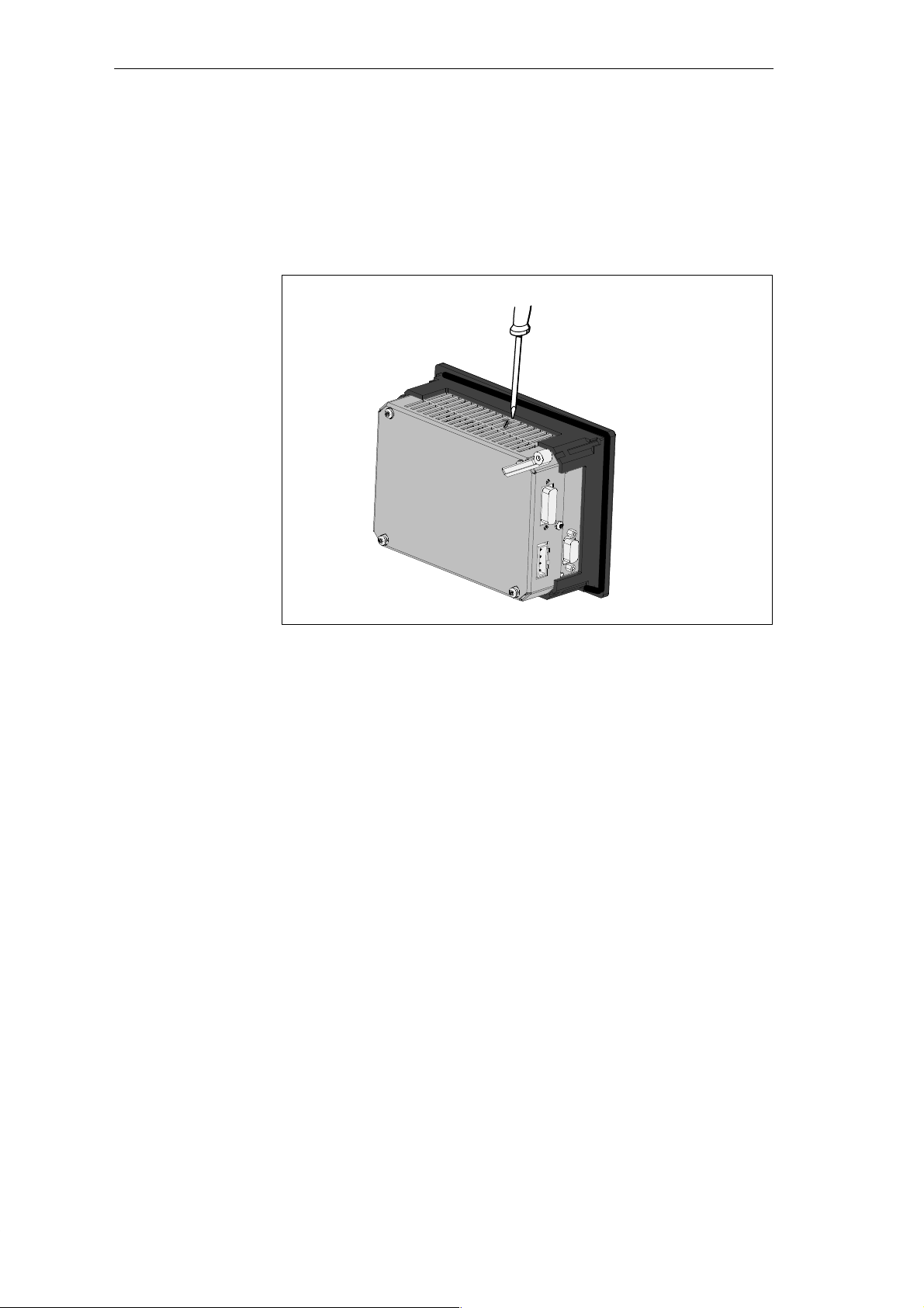
You can set the contrast of the C7 display using the screw as shown in Figure
2-13 and adapt the contrast to the lighting conditions.
Figure 2-13 Setting the Contrast
C7-621 / C7-621 AS-i Control Systems
C79000-G7076-C621-01
2-17
Page 36

Installing and Preparing the C7
2.9 I/O Expansion with the IM 621
Additional S7-300
Modules
Requirements
Connecting the
Additional I/Os
You can connect further S7-300 I/Os to the C7 via the P bus connector of the
C7-621 or C7-621 AS-i.
How you install the S7 modules, is described in the manual /71/.
Note
You can connect a maximum of four I/O modules to the C7.
The S7-300 system must have an IM 621 interface module.
Connect the additional I/Os as following:
1. Install the additional I/O modules as described for the rack in the
manual /70/.
2. Connect the C7-621 or C7-621 AS-i to the IM 621 interface module via
an IM 621 standard cable (for the connection to C7, see also Figure 2-9).
An IM 621 cable is supplied with the module and is connected to the IM
621 interface module.
The first time you start up the C7, it detects the connected additional
modules.
Addresses
P Bus Interface
2-18
Addressing on the C7 is described in Volume 2 Chapter 4.
The C7 has an integrated P bus interface for I/O expansions with external
S7-300 standard I/Os.
C7-621 / C7-621 AS-i Control Systems
C79000-G7076-C621-01
Page 37
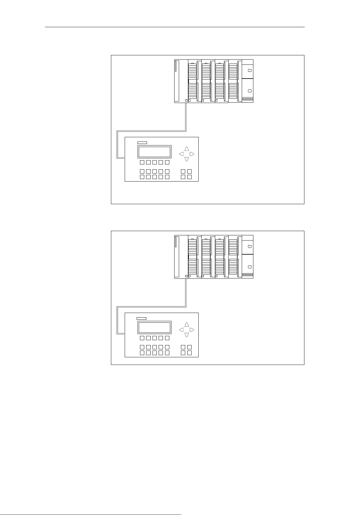
Installing and Preparing the C7
Modules
Slot number
Digital address
Analog address
Figure 2-14 Maximum Configuration with a C7-621
Slot number
IM 621
IM 621
45 67
124.0...125.7
128...135
56 78
Modules
Figure 2-15 Maximum Configuration for a C7-621 AS-i
C7-621 / C7-621 AS-i Control Systems
C79000-G7076-C621-01
2-19
Page 38

Installing and Preparing the C7
2.10 Memory Reset on the C7
Memory Reset on
the C7 OP
Memory Reset on
the C7 CPU
The C7 must be turned off. To reset the memory of the C7 OP, follow the
steps outlined below:
1. Press and hold down the following keys at the same time:
2. Turn on the power to the C7.
3. Wait until a line appears under the text FLASHTEST.
4. The C7 OP then starts up with English texts.
5. Following this the memory of the C7 OP is reset, in other words the
C7 OP is reinitialized and the entire configuration is deleted.
Note
The default configuration contained in the firmware in English remains
available and can be worked with.
A memory reset on the C7 CPU means that the C7 CPU is reinitialized, the
current user program in the RAM is deleted and any user program currently
in the flash memory of the C7 CPU is reloaded.
There are two ways of resetting the C7 CPU memory:
S Memory reset using the C7 system function “C7 CPU Mode” on the C7
S Memory reset using the PG function (see programming device manual)
A memory reset using the PG function is only possible with the C7 CPU in
the STOP mode.
2-20
C7-621 / C7-621 AS-i Control Systems
C79000-G7076-C621-01
Page 39
Installing and Preparing the C7
Memory Reset on
the C7 CPU Using
the System
Function
The section below describes how to reset the C7 CPU memory with the
C7 CPU Mode system function:
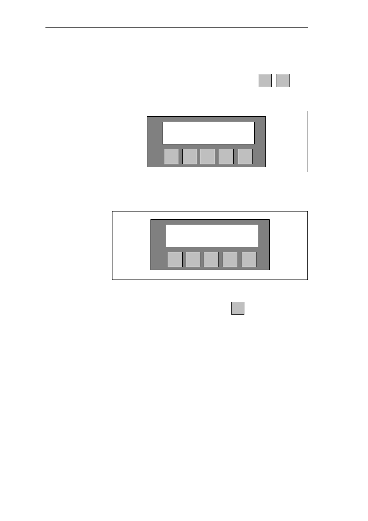
1. Select the system functions menu by pressing the keys
SHIFT
0
The following is displayed on the C7-621:
C7Ć621
C7 System Functions
KEY IN/OUT
F1 F2 F3 F4 F5
Figure 2-16 C7-621 System Functions Menu with Function Keys
or for the C7-621 AS-i
C7Ć621 ASĆi
C7 System Functions
KEY AS-i
F1 F2 F3 F4 F5
Figure 2-17 C7-621 AS-i System Functions Menu with Function Keys
2. Select the C7 CPU Mode menu by pressing
F1
If you have not yet entered a password, this will be requested.
3. Enter the password (this is explained in Volume 2 Section 7.6).
C7-621 / C7-621 AS-i Control Systems
C79000-G7076-C621-01
2-21
Page 40
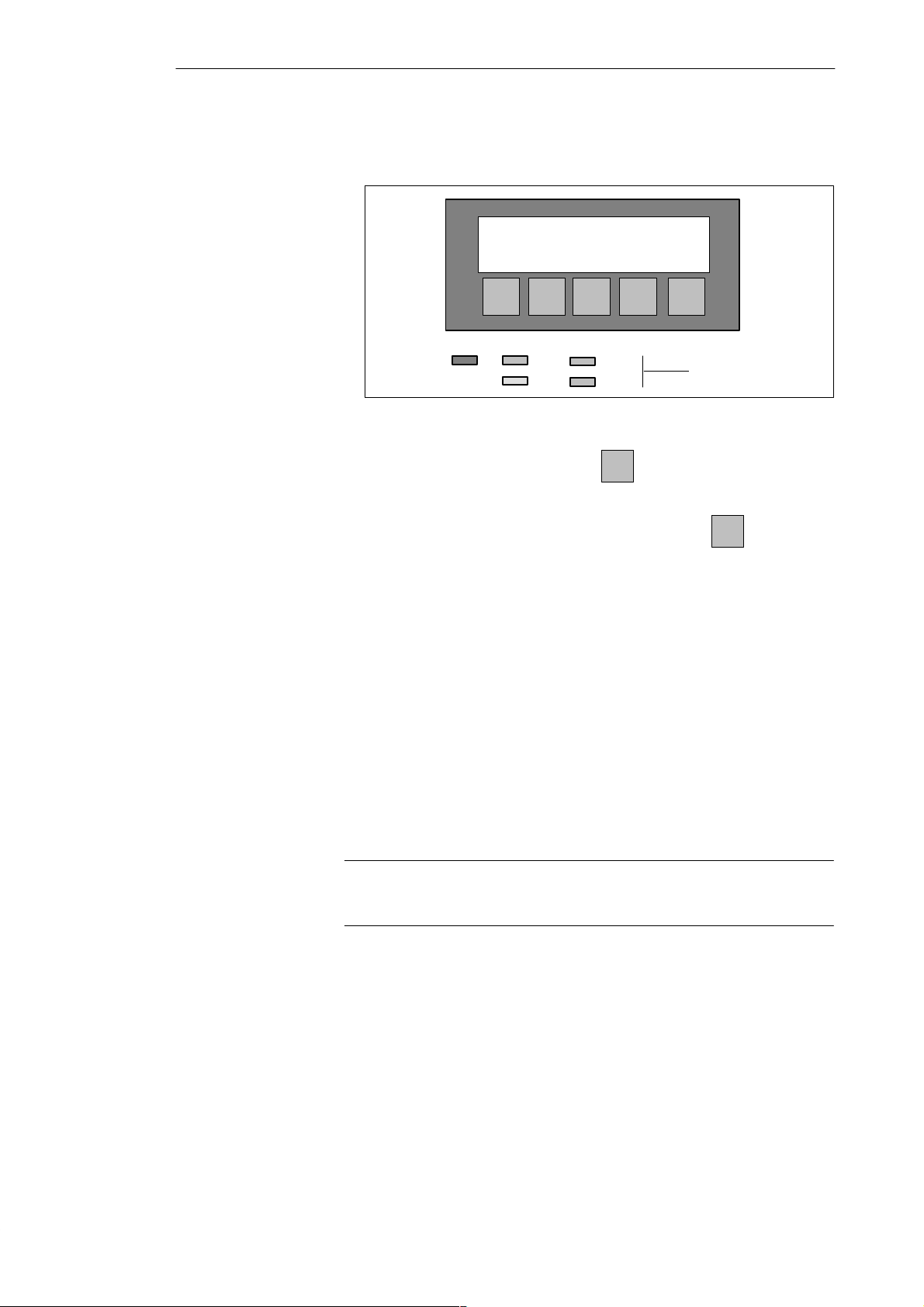
Installing and Preparing the C7
The following menu is displayed.
MODE:STOP
RUNP RUN STOP MRES
SF DC5V
FRCE
Figure 2-18 “C7 CPU Modes” Menu with Function Keys
4. Select the STOP function by pressing
= Anwahl der
DIR–Funktion
RUN
STOP
.
LED displays
The STOP LED lights up.
5. Select the MRES (Memory Reset) function by pressing
and wait
until the STOP LED goes off twice.
6. Immediately after the STOP LED lights up again:
Select STOP and immediately afterwards MRES (within 1 second). If
there is more than 1 second between pressing the two keys, the memory
reset is not performed.
Result:
– When the STOP LED flashes quickly for approximately 3 seconds and
is then lit continuously again, the memory on the C7 CPU has been
reset.
– If the STOP LED of the C7 lights up without first flashing, then repeat
Steps 4 and 5.
7. Following the memory reset, you must set the C7 CPU explicitly to STOP
or RUN/RUNP otherwise the C7 CPU is still set to MRES.
Note
A memory reset does not affect the content of the C7 CPU flash memory.
How to delete the content of the flash memory is described in Volume 2,
Section 3.8.
2-22
C7-621 / C7-621 AS-i Control Systems
C79000-G7076-C621-01
Page 41
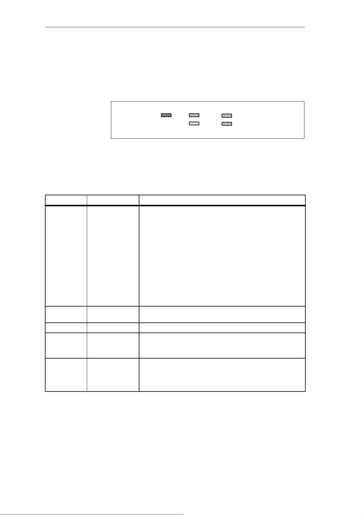
2.11 Status and Error LEDs on the C7
Installing and Preparing the C7
Status and Error
The C7-621 or C7-621 AS-i has the following status and error LEDs:
LEDs
SF DC5V
FRCE
Figure 2-19 Status and Error LEDs of the C7-621 or C7-621 AS-i
Meaning of the
Status and Error
The status and error LEDs are explained in the order in which they appear on
the C7.
LEDs
LED Meaning Explanation
SF (red) C7 CPU group error Lights up in the following situations:
S Hardware faults
S Firmware errors
S Programming errors
S Parameter assignment errors
S Math errors
S Time errors
S Defective internal memory
S I/O fault/error in the internal I/O functions
RUN
STOP
DC5V (green) 5V DC power supply
for the C7
FRCE (yellow) Reserved RUN (green) RUN or RUNP mode
on the C7 CPU
STOP (yellow) STOP mode on the
C7 CPU
C7-621 / C7-621 AS-i Control Systems
C79000-G7076-C621-01
T o find out the exact cause of the problem read out the
diagnostic buffer using a programming device..
Lights up when the internal 5V DC power supply is functioning
correctly.
Lights up when the C7 is executing the user program.
Flashes (several times) during the C7 startup. After the STOP LED goes
off, the outputs are enabled.
Lights up when the C7 is not executing the user program.
Flashes at 1 second intervals when a memory reset has been requested by
the operator or by the C7 CPU.
Flashes twice; refer to installation.
2-23
Page 42

Installing and Preparing the C7
2.12 Clocks on the C7
Overview
Clock on the
C7 CPU
Default
C7 CPU Time
Master Clock
Setting and
Reading Out the
C7 CPU Clock
The C7 devices have two software clocks:
S One clock on the C7 CPU
S One clock in the C7 OP
The clock of the C7 CPU is a software clock. This clock is independent of
the clock of the C7 OP.
When the unit is shipped, the following value is set:
DT#1994-0-01-00:00:00.
As an integrated clock, the C7 CPU clock can also function as the master
clock within the C7 I/O configuration.
You set and read the time as follows:
S With a programming device using STEP 7
or
S In the STEP 7 user program using SFC 0 “SET_CLK”. With SFC 1
“READ_CLK” you can read out the current time (refer to the reference
manual /235/).
Clock Reaction to
Power Off
Clock on the
C7 OP
Default OP Time
Setting and
Reading Out the
C7 OP Clock
2-24
If the power is turned off, the current time is saved in the non-volatile
memory . When power is turned on again, the clock continues to run starting
from the saved time.
When the power is turned off, the C7 CPU clock itself stops.
The clock on the C7 OP is independent of the clock on the C7 CPU. When
the power is turned off, the C7 OP clock stops.
When the device is shipped, the clock is set to the following value:
01.01.94 -00:00.
You set the time as follows:
S Using a job in the user program and interface block.
or
S Online by selecting the special display “Time/Date” if this was
configured.
C7-621 / C7-621 AS-i Control Systems
C79000-G7076-C621-01
Page 43

Installing and Preparing the C7
Run-Time Meter
The C7 CPU is equipped with a run-time meter.
This allows you to count the operating hours of the C7 CPU or a resource it
controls.
You program the run-time meter in the user program using the SFCs 2
“SET_R TM”, 3 “CTRL_RTM” and 4 “READ_RTM” (see
reference manual /235/).
C7-621 / C7-621 AS-i Control Systems
C79000-G7076-C621-01
2-25
Page 44

Installing and Preparing the C7
2-26
C7-621 / C7-621 AS-i Control Systems
C79000-G7076-C621-01
Page 45
Configuring an MPI Network
3
In this Chapter
Chapter
Overview
This chapter describes how to configure an MPI network. You will learn the
following:
S Which communication options are available to you with an MPI network.
S The components to which you can connect the nodes of an MPI network.
S The maximum and minimum cable lengths you can use.
S How to connect the PROFIBUS LAN cable to the bus connector.
S How to use an RS 485 repeater.
S Special considerations when connecting a programming device.
Before the individual nodes on an MPI network can communicate with each
other, you must assign MPI addresses to them. How you assign MPI
addresses and the rules to be observed are described in the user manual /231/.
for S7 and in the ProTool documentation for the C7 OP.
Volume 2 of this manual, Section 3.4.10 contains the information you require
for configuring communication with specific C7 CPUs.
Section
3.1 Communication via the MPI Interface 3-2
3.2 Rules for Configuring an MPI Network 3-4
3.3 Cable Lengths 3-8
3.4 Network Components 3-10
3.5 Bus Connectors 3-12
3.5.1 PROFIBUS Bus Connector 3-13
3.5.2 Bus Connector 6ES7 972-0B.20-0XA0 3-14
3.5.3 Bus Connector 6ES7 972-0B.10-0XA0 3-17
3.5.4 Plugging the Bus Connector into a Module 3-19
Description Page
C7-621 / C7-621 AS-i Control Systems
C79000-G7076-C621-01
3-1
Page 46

Configuring an MPI Network
3.1 Communication via the MPI Interface
Definition:
Multipoint
Interface MPI
Transmission Rate
Connectable
Devices
Device/Node
The C7 interface for connecting devices such as programming devices is
known as the Multipoint Interface since several devices at different locations
(points) can communicate with the C7 via this interface.
The transmission rate of the C7 is fixed at 187.5 Kbps.
You can create an MPI network by interconnecting the following devices:
S Programming devices (PG/PC)
S Operator interface systems (OPs)
S S7-300 / M7-300
S S7-400 / M7-400
S Further C7s
S FMs, CPs
Convention: In the following sections, all the devices interconnected on an
MPI network will be called nodes. Please note that the C7 itself occupies two
MPI addresses and therefore represents two nodes, as follows:
– One for the C7 CPU
Segment
Number of Nodes
MPI Addresses
– One for the C7 OP
A segment is a section of the network between two terminating resistors. A
segment can include up to 32 nodes. A segment is also limited by the
maximum permitted cable length that depends on the transmission rate (see
Section 3.3)
You can interconnect up to 126 (addressable) nodes on an MPI network.
T o allow all the nodes connected to the MPI network to communicate with
each other, you must assign an MPI address to each node and you must also
set a highest MPI address. Before you network the nodes, you must assign the
MPI addresses individually on a programming device.
Note
The RS 485 repeater is not assigned an MPI address.
3-2
C7-621 / C7-621 AS-i Control Systems
C79000-G7076-C621-01
Page 47
Configuring an MPI Network
Default MPI
Addresses of the
C7
Rules for MPI
Addresses
CPU-CPU
Communication
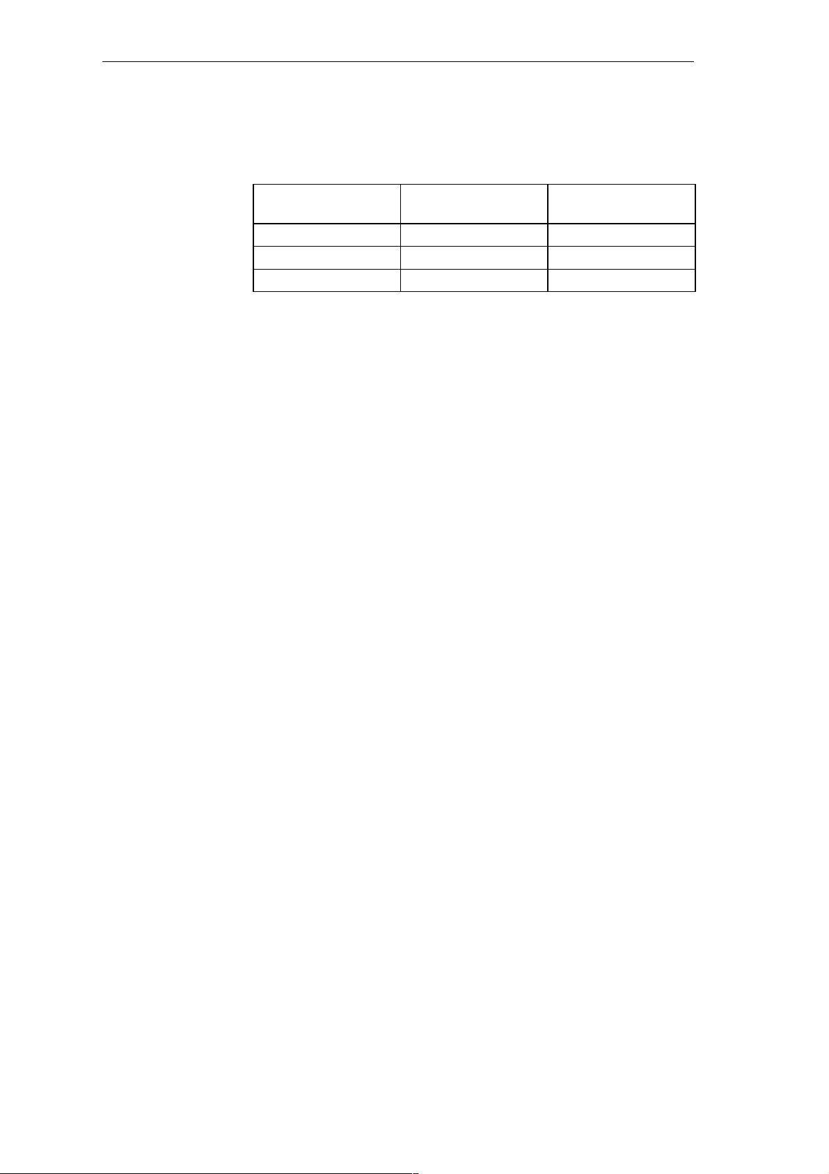
The following table shows the default MPI addresses set on the devices when
they are shipped.
Node (Device)
Default
MPI Address
Default Highest MPI
Address
PG 0 15
C7 OP 1 Depends on the OP
C7 CPU 2 15
When assigning MPI addresses, keep to the following rules:
S Each MPI address within an MPI network must be unique.
S The highest possible MPI address must be higher than the highest actual
MPI address and must be set to the same value on all nodes. (Exception:
connecting a programming device to several nodes; see Chapter 4).
A CPU can communicate with up to four C7 CPUs or S7-300 CPUs. These
can exchange shared data with each other. For more detailed information
about shared data, refer to the manual /231/.
GD Circles
The transmission and reception of shared data is organized in GD circles.
Each C7 CPU can be included in up to four different GD circles.
C7-621 / C7-621 AS-i Control Systems
C79000-G7076-C621-01
3-3
Page 48

Configuring an MPI Network
3.2 Rules for Configuring an MPI Network
Overview
Rules
This section deals with the following topics:
S How to configure an MPI network
S Rules for configuring the network
Remember the following rules when connecting nodes to an MPI network:
S Before interconnecting the individual nodes of the MPI network, you
must first assign the MPI address and the highest MPI address to each
node (except for the RS 485 repeater).
Tip: Put a label with the MPI address on the housing of all the nodes in
the MPI network. This means that you can always see which MPI address
has been assigned to which node in your system.
S Connect up all the nodes on the MPI network as shown in Figure 3-3, in
other words integrate the stationary programming devices and OPs
directly in the MPI network.
This means that only the programming devices or OPs required for
installation or maintenance must be connected via tap lines to the MPI
network.
S If you operate more than 32 nodes in a network, the bus segments must be
connected via RS 485 repeaters.
S Ungrounded bus segments and grounded bus segments are connected via
RS 485 repeaters.
3-4
S Each RS 485 repeater in the network reduces the maximum number of
nodes per bus segment. This means that if there is an RS 485 repeater in a
bus segment, the maximum number of other nodes is reduced to 31 for
this segment. The number of RS 485 repeaters in the network, however,
does not affect the maximum number of nodes on the network.
Up to 10 segments can be connected in series.
S Activate the terminating resistor on the first and last node in a segment.
S Before you include a new node in the MPI network, you must first turn
off its power supply.
C7-621 / C7-621 AS-i Control Systems
C79000-G7076-C621-01
Page 49
Configuring an MPI Network
Recommendation
for MPI Addresses
on the Network
Components
Using the RS 485
Repeater
Terminating
Resistor
Avoid assigning the default MPI addresses (see below) as fixed node
addresses in the network otherwise address conflicts can occur when you
replace devices or expand the network (MPI addresses assigned twice).
S Reserve MPI address “0” for a service programming device
S Reserve address “1” for the C7 OP
S Reserve address “2” for the C7 CPU.
This avoids double assignment of MPI addresses if you install a further C7 or
S7-300 with its default address (for example when replacing a C7).
The individual components are interconnected via bus connectors and the
PROFIBUS LAN cable. Remember to use a bus connector with a PG
interface for nodes to which a PG might need to be connected (see also
Section 3.5).
T o connect two segments or to extend the length of the cable, use RS 485
repeaters.
Installing and using the repeater is explained in the reference manual /71/.
A cable must be terminated by its characteristic resistance. This is achieved
simply by activating the integrated terminating resistor on the first and last
node of a network.
Terminating
Resistor on the
Bus Connector
Remember that the terminating resistor requires power to be effective. Make
sure that the power supply to the nodes on which the terminating resistor is
activated is on during startup and operation.
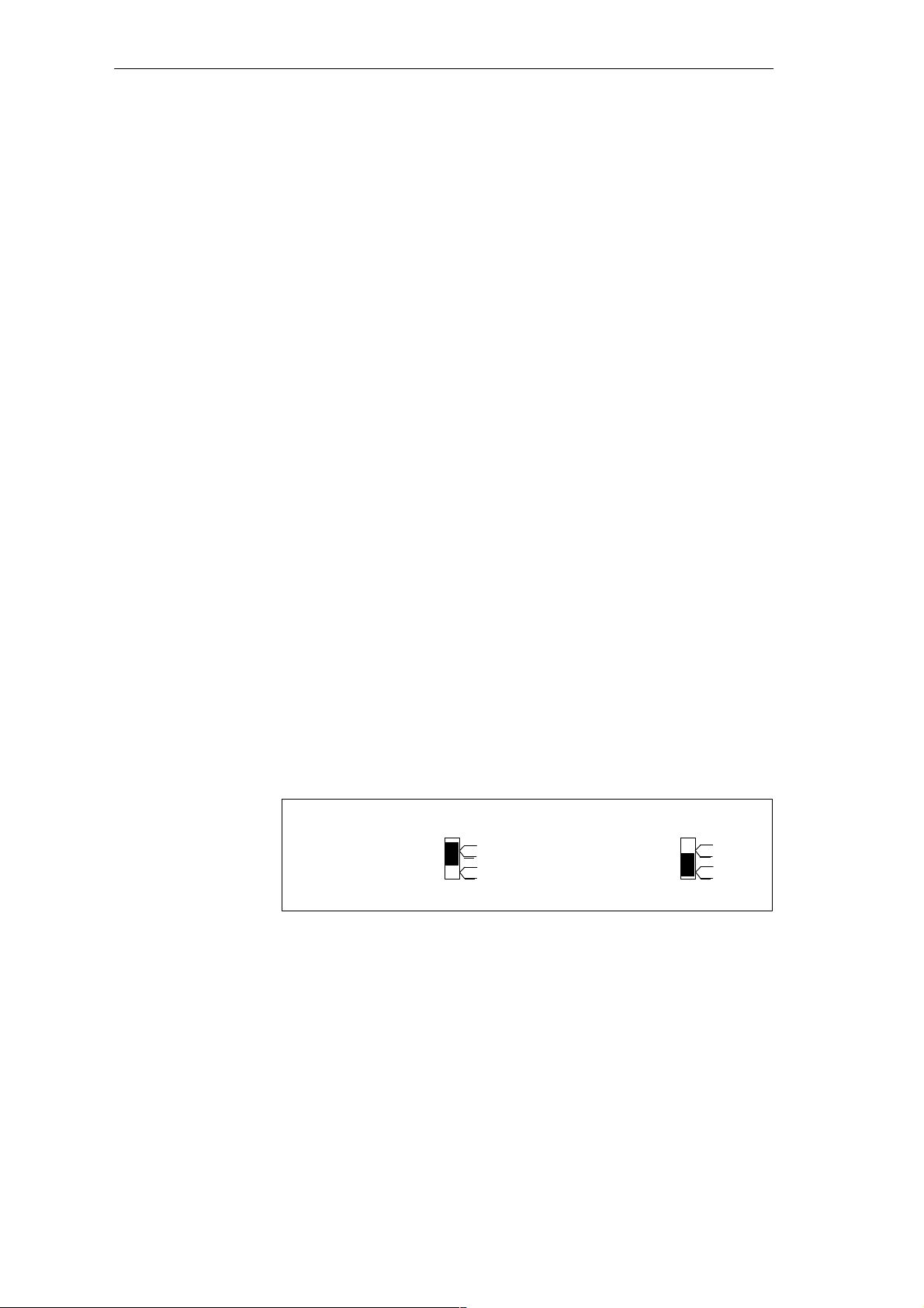
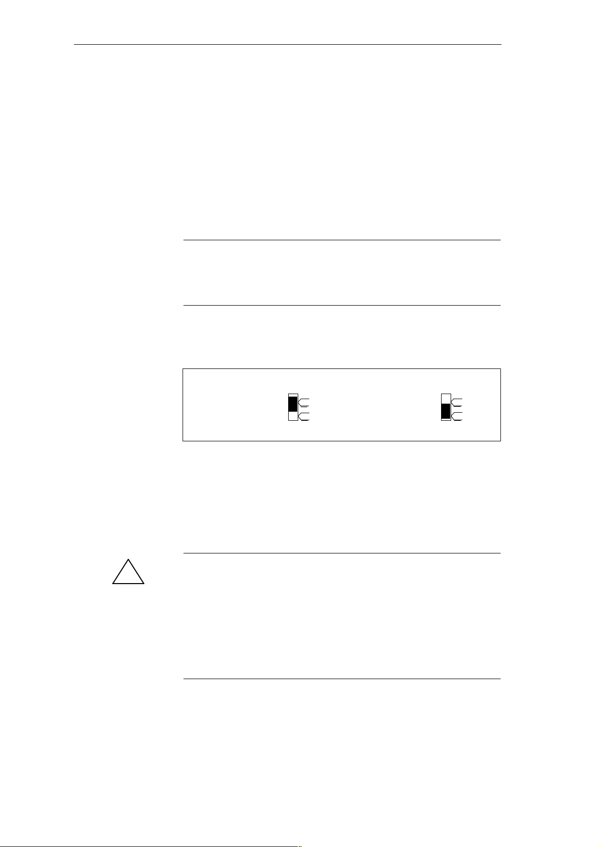
Figure 3-1 shows you the switch settings for the terminating resistor on the
bus connector.
Terminating
resistor on
Figure 3-1 Terminating Resistor on the Bus Connector (On and Off)
on
off
Terminating resistor
off
on
off
C7-621 / C7-621 AS-i Control Systems
C79000-G7076-C621-01
3-5
Page 50
Configuring an MPI Network
Terminating
Resistor on the RS
485 Repeater
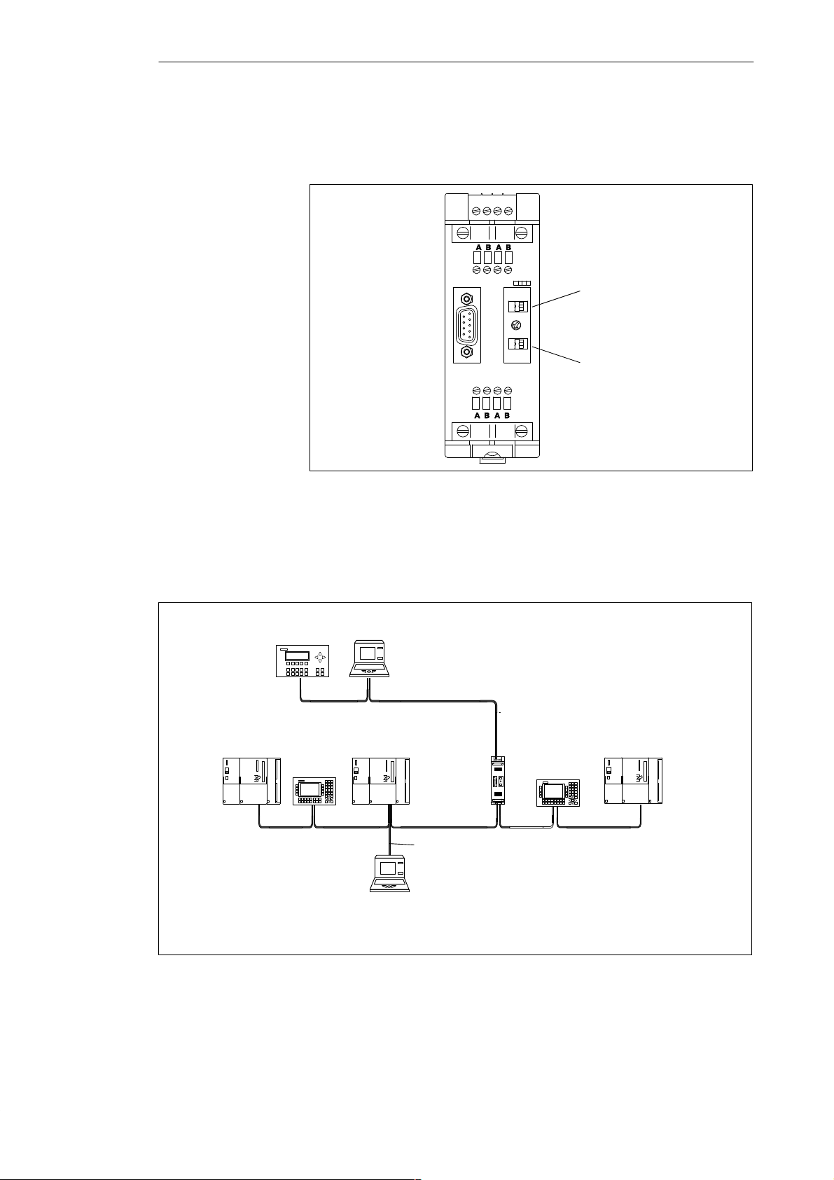
Figure 3-2 shows the switches on the RS 485 repeater for activating the
terminating resistor.
DC
L+ M PE M 5.2
24 V
ON
ON
SIEMENS
Figure 3-2 Terminating Resistor on the RS 485 Repeater
Terminating resistor
bus segment 1
Terminating resistor
bus segment 2
Example of
Termination in an
Figure 3-3 shows a possible MPI configuration in which the terminating
resistor must be activated.
MPI Network
C7
À
S7-300
OP 25
À
* Only connected during installation/maintenance via a tap line
Terminating resistor activated
À
PG
S7-300
RS 485
repeater
Connecting
cable
PG*
➀
OP 25
S7-300
À
Figure 3-3 Activating Terminating Resistors in an MPI Network
3-6
C7-621 / C7-621 AS-i Control Systems
C79000-G7076-C621-01
Page 51
Configuring an MPI Network
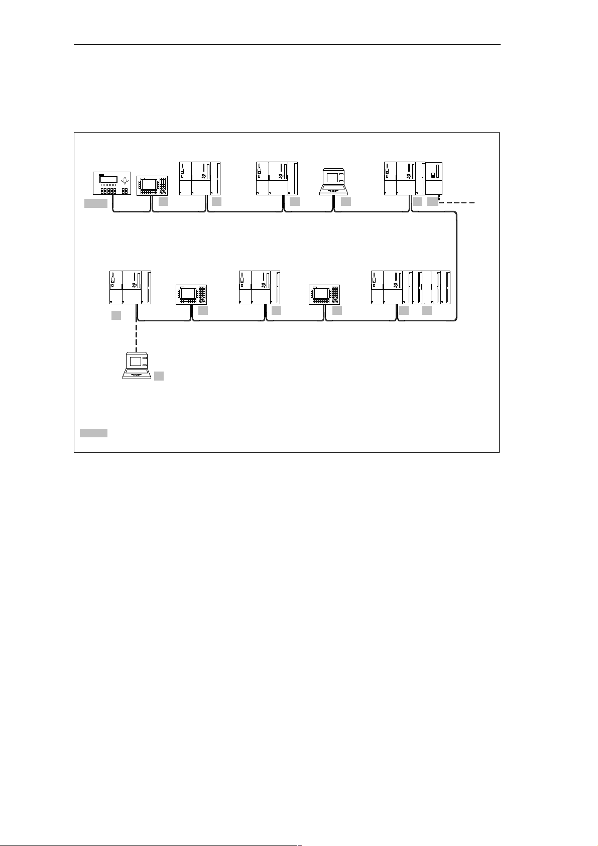
Example of an MPI
Subnet
C7
3 + 4
* Only during installation/maintenance connected via a tap line (with the default MPI address)
** Connected later to the MPI subnet (with default MPI address)
*** Apart from the MPI address (here address 7), the CP also has a PROFIBUS address
0 ... x MPI addresses of the nodes
➀ Terminating resistor activated
16
OP 25**
À
À
PG*
Figure 3-4 shows the basic configuration of an MPI subnet using the rules
listed above.
S7-300 S7-300
56 78
S7-300S7-300
OP 25 OP 25
0
PG
S7-300
9
S7-300
12
CP
10
FM
11131415
PROFIBUS
subnet***
Figure 3-4 Example of an MPI Subnet
C7-621 / C7-621 AS-i Control Systems
C79000-G7076-C621-01
3-7
Page 52
Configuring an MPI Network
3.3 Cable Lengths
Segment in an MPI
Network
Longer Cable
Lengths
C7
The maximum cable length in one segment of an MPI network is 50 m.
These 50 m represent the distance from the first node to the last node on the
segment.
If you require longer cable lengths than permitted in one segment, you must
then use RS 485 repeaters. The maximum possible cable length between RS
485 repeaters corresponds to the cable length of a segment. Remember,
however, that when using these maximum lengths, no further node (remote
segment) can be located between the two RS 485 repeaters. You can connect
up to nine RS 485 repeaters in series.
If you use an RS 485 repeater, remember that this must also be included in
the number of nodes when calculating the number of nodes although it is not
assigned its own MPI number.
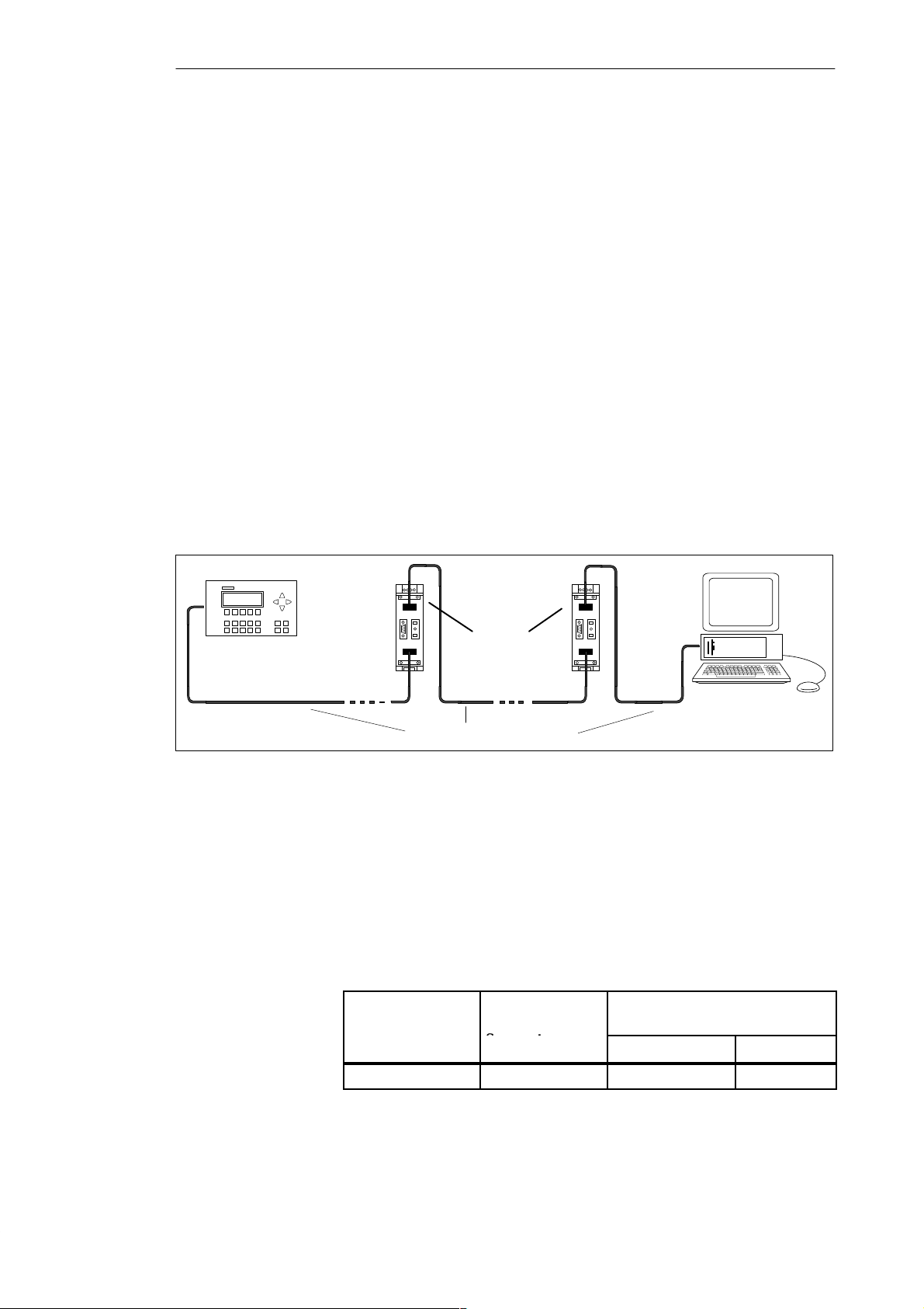
Figure 3-5 shows how the cable for an MPI network can be extended using
RS 485 repeaters.
RS 485
repeater
50 m 1000 m 50 m
(remote segment)
PROFIBUS LAN cable
Figure 3-5 Maximum Cable Length Between Two RS 485 Repeaters
Tap Lines
T ap lines are cables with which the programming devices or OPs can be
connected to the network for installation or during maintenance. T ap lines
should be kept as short as possible. The number and length of tap lines that
can be used is restricted.
The following table shows the maximum length of tap lines per bus segment:
Table 3-1 Length of the Tap Lines per Segment
Transmission
Rate
Max. Length of
Tap Line per
Segment
187.5 Kbps 75 m 32 25
Number of Nodes with Tap Line
Lengths of ...
1.5 m or 1.6 m 3 m
3-8
C7-621 / C7-621 AS-i Control Systems
C79000-G7076-C621-01
Page 53
Configuring an MPI Network
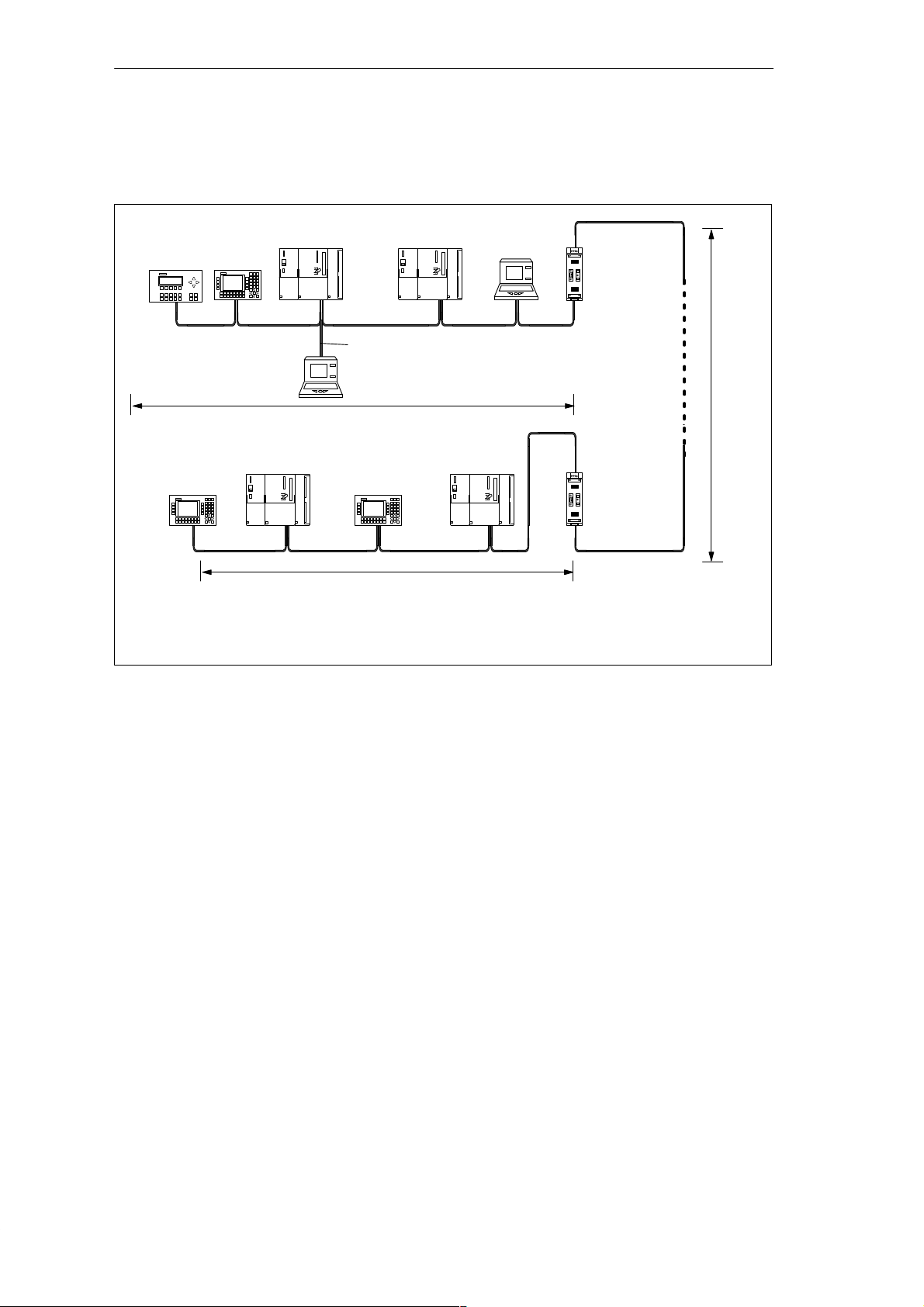
Example
Figure 3-6 shows a possible MPI network configuration. The example
illustrates the distances that can be achieved in an MPI network.
S7-300 S7-300
C7
À
À
Terminating resistor activated
➁ PG connected via tap line for maintenance
0 ... x MPI addresses of the nodes
OP 25
3+4 5 6 7
OP 25
12
À
PG*
max. 50 m
S7-300 S7-300
➁
0
max. 50 m
Connecting cable
OP 25
91011
PG*
À
RS 485
repeater
8
À
max.
1000 m
”Remote Segment”
À
RS 485
repeater
À
Figure 3-6 Cable Lengths in an MPI Network
C7-621 / C7-621 AS-i Control Systems
C79000-G7076-C621-01
3-9
Page 54
Configuring an MPI Network
3.4 Network Components
Purpose
PROFIBUS LAN
Cable
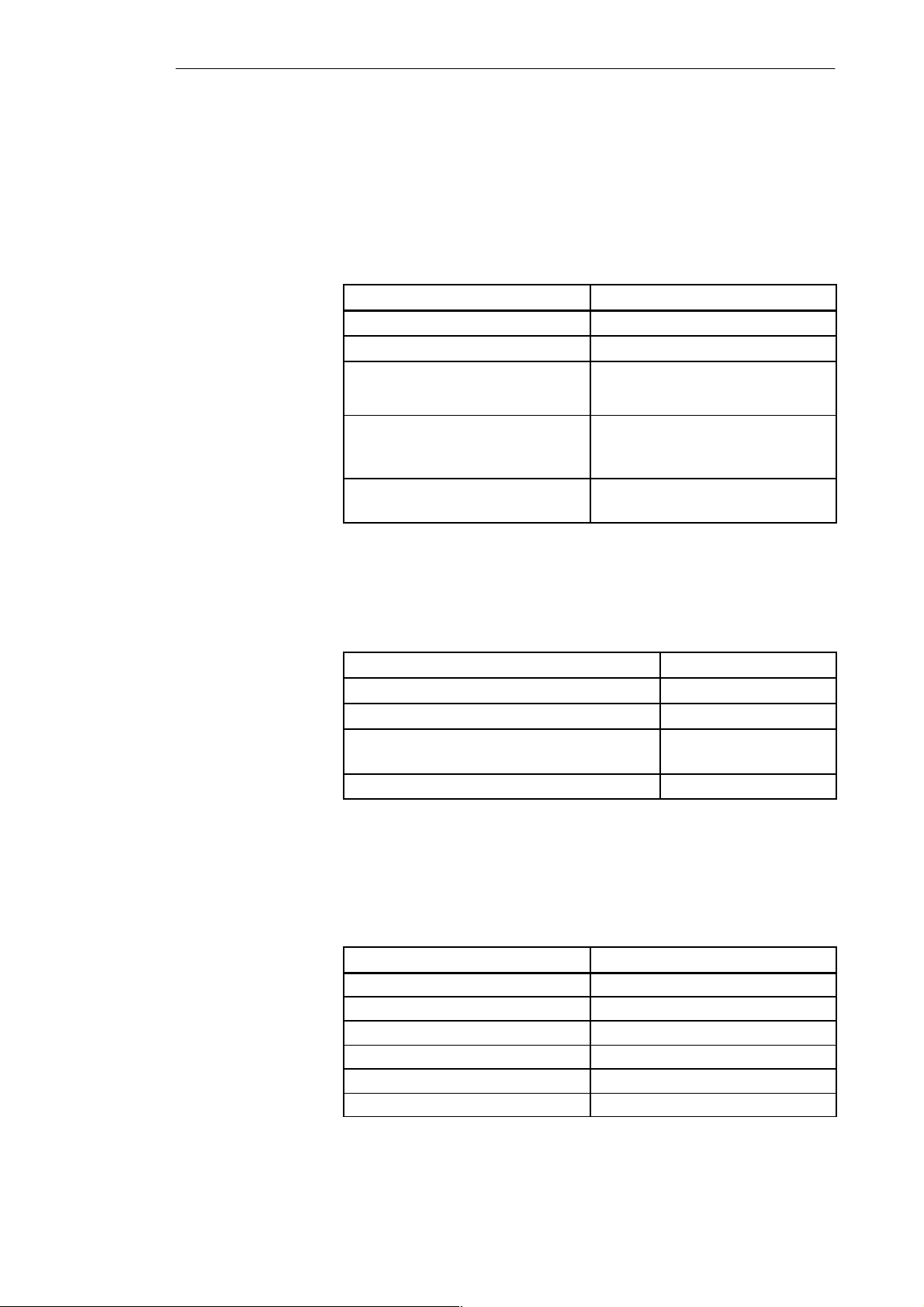
You require network components in the following situations:
Table 3-2 Network Components
Purpose Component
... to install the network PROFIBUS LAN cable
... to connect a node to the network Bus connector
... to amplify the signal
RS 485 repeater
... to link segments
... to convert signals for fiber-optic
Optical link module
transmission (only PROFIBUS DP
networks)
... to connect programming
PG connecting cable (tap line)
devices/OPs to the network
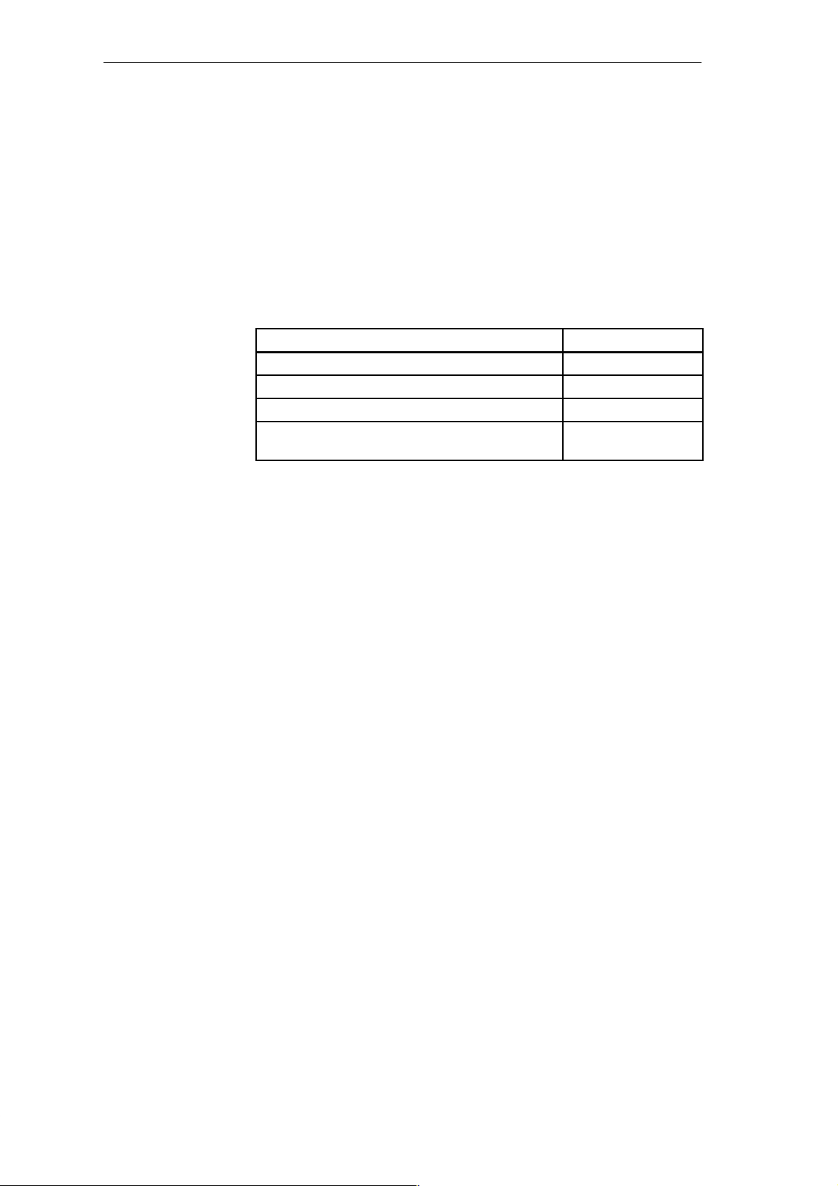
The following PROFIBUS LAN cables are available:
Table 3-3 LAN Cables
PROFIBUS LAN cable 6XV1 830-0AH10
PROFIBUS underground cable 6XV1 830-3AH10
PROFIBUS trailing cable 6XV1 830-3BH10
PROFIBUS LAN cable with PE sheath (for the
6XV1 830-0BH10
food, drinks and tobacco industry)
PROFIBUS LAN cable for festoons 6XV1 830-3CH10
Characteristics of
the PROFIBUS
LAN cable
3-10
The PROFIBUS LAN cable is a shielded twisted pair cable with the
following characteristics:
Table 3-4 Characteristics of the PROFIBUS LAN Cable
Characteristics Values
Characteristic resistance Approx. 135 to 160 Ω (f = 3 to 20 MHz)
DC loop resistance x 115 Ω/km
Operating capacitance 30 nF/km
Attenuation 0.9 dB/100 m (f = 200 kHz)
Permitted core cross-section 0.3 mm2 to 0.5 mm
Permitted cable diameter 8 mm " 0.5 mm
C7-621 / C7-621 AS-i Control Systems
2
C79000-G7076-C621-01
Page 55
Configuring an MPI Network
Cabling Rules
When laying the PROFIBUS LAN cable, make sure you keep to the
following rules:
S Do not twist the cable
S Do not stretch the cable
S Do not crimp the cable
When laying the interior LAN cable, the following restrictions must also be
taken into account (d
Table 3-5 Restrictions when Laying the Interior LAN Cable
Bending radius (bending once) w 80 mm (10 dO)
Bending radius (repeated bending) w 160 mm (20 dO)
Permitted temperature range during installation - 5 _C to + 50 _C
Permitted temperature range during storage and
when installed
= outer diameter of the cable):
O
Characteristics Limits
- 30 _C to + 65 _C
C7-621 / C7-621 AS-i Control Systems
C79000-G7076-C621-01
3-11
Page 56

Configuring an MPI Network
3.5 Bus Connectors
Purpose of the
Bus Connector
No Area of
Application
The bus connector is used to connect the PROFIBUS LAN cable to the MPI
interface. This establishes the connection to further nodes.
There are five different bus connectors:
S Up to 12 Mbps PROFIBUS bus connector (6GK1500-0EA00)
S Up to 12 Mbps
– Without PG interface (6ES7 972-0BA10-0XA0)
– With PG interface (6ES7 972-0BB10-0XA0)
S Up to 12 Mbps, with swivelling cable outlet (straight or angled)
– Without PG interface (6ES7 972-0BA20-0XA0)
– With PG interface (6ES7 972-0BB20-0XA0)
You do not require a bus connector for the RS 485 repeater.
3-12
C7-621 / C7-621 AS-i Control Systems
C79000-G7076-C621-01
Page 57
3.5.1 PROFIBUS Bus Connector
Configuring an MPI Network
Appearance
(6GK15000-0EA00.)
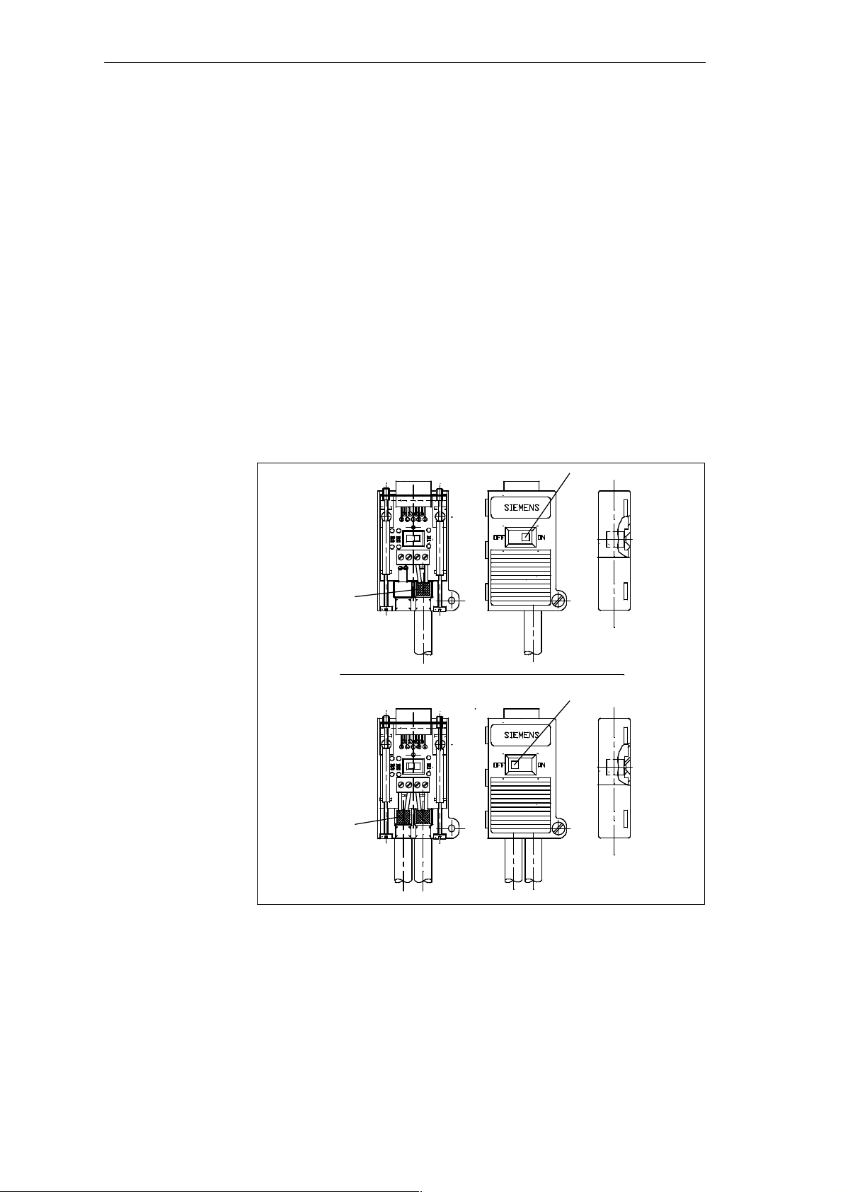
Figure 3-7 shows the PROFIBUS bus connector with order number
6GK1500-0EA00
Figure II:
Bus connector for the first and last node on the PROFIBUS network. The
cable can be connected either from the left or right.
① Switch setting for the first and last station on the PROFIBUS network:
“ON” (terminating resistor activated).
② The cable shield must lie on the bare metal.
Figure III:
① Terminator resistor deactivated.
② The cable shield must lie on bare metal.
II
①
②
Figure 3-7 Appearance of the PROFIBUS Bus Connector
C7-621 / C7-621 AS-i Control Systems
C79000-G7076-C621-01
III
①
②
3-13
Page 58
Configuring an MPI Network
Fitting the
Connector to the
LAN Cable
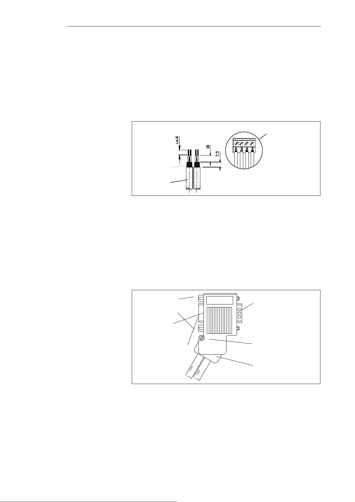
Fit the PROFIBUS bus connector with order number 6GK1500-0EA00 to the
LAN cable as follows:
1. Strip the cable.
2. Insert the green and red wires into the screw terminals.
3. Press the cable sheath between the two clips.
4. Tighten the screw terminals to secure the green and red wires.
Screw terminal block
for LAN cable
connection
Cable shield
PROFIBUS LAN
cable
6XV1 830-0AH10
Figure 3-8 Connecting the PROFIBUS LAN Cable to the Screw Terminal Block
3.5.2 Bus Connector 6ES7 972-0B.20-0XA0
Appearance
(6ES7-972-0B.20 ...)
Figure 3-9 shows the bus connector with order number 6ES7 972-0B.20 ...:
Screws for
securing to the
station
Switch for
terminating resistor
PG interface (only with
6ES7 972-0BB20-0XA0)
Figure 3-9 Appearance of the Bus Connector (Order Number 6ES7 972-0B.20 ...)
9-pin sub D connector
for connection to the
station
Casing screw
Hinged clamp for
vertical or
30° cable outlet
3-14
C7-621 / C7-621 AS-i Control Systems
C79000-G7076-C621-01
Page 59
Configuring an MPI Network
Fitting the Bus
Connector to the
LAN Cable
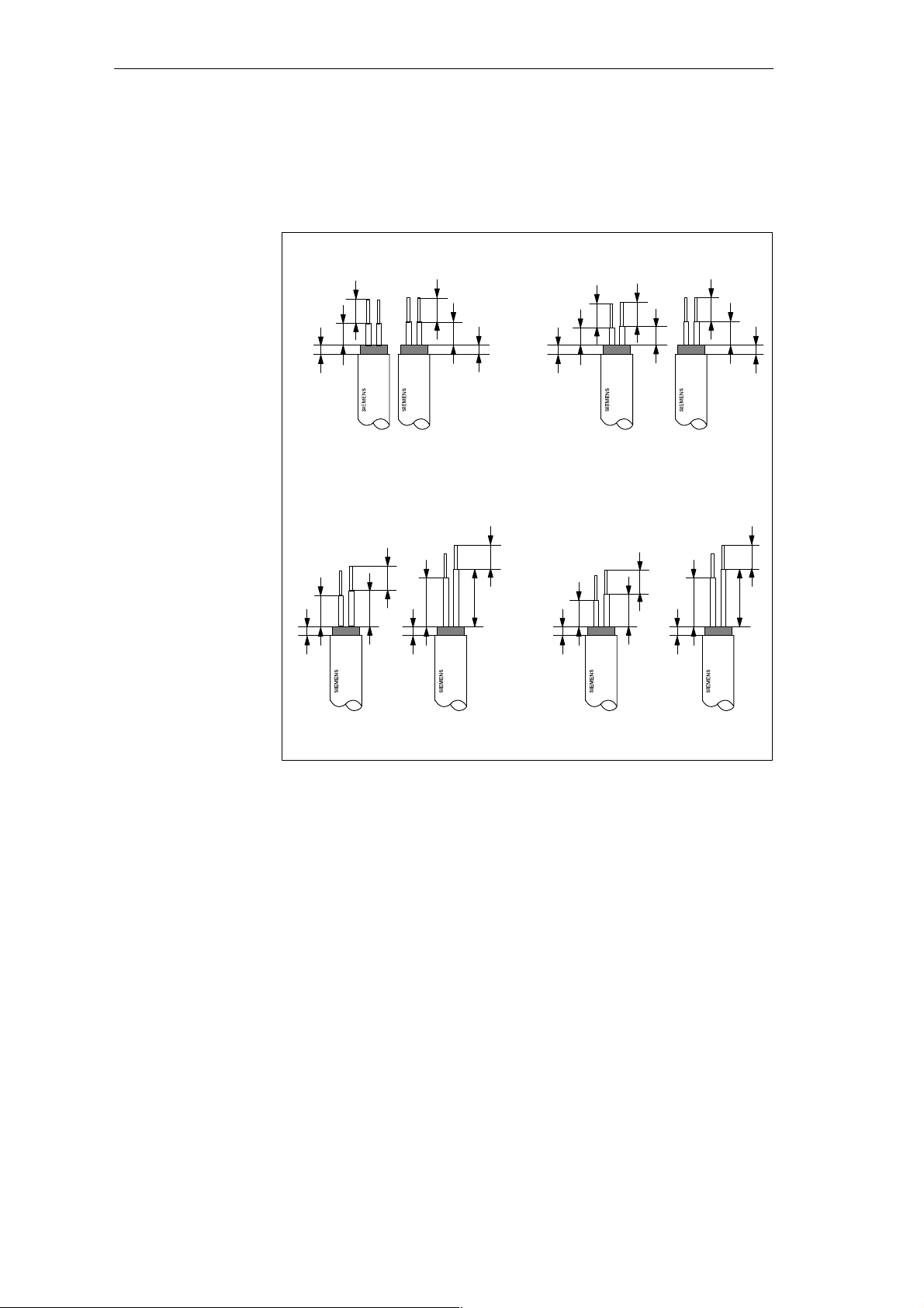
Fit the bus connector with order number 6ES7 972-0B.20 ... to the LAN
cable as follows:
1. Strip the insulation from the LAN cable as shown in Figure 3-10.
Vertical Cable Outlet
AB
5.5
5
2
AB
Without PG interface
B
A
7
5.5
8
5.5
5.3
2
Angled Cable Outlet
B
A
11
13
2
5.5
AB
5.5
4
With PG interface
B
A
6
5.5
4,3
5.5
AB
A
11
B
5.5
5.3
2
5.5
13
2
2
Without PG interface
2
With PG interface
7,3
2
Figure 3-10 Length of Insulation to be Removed when Fitting the Bus Connector
(6ES7 972-0B.20 ...)
2. Open the casing of the bus connector by undoing the screw and lifting the
cover.
3. Release the cover of the hinged clamp.
4. The bus connector with order number 6ES7 972-0B.20 is shipped with the
cable outlet at 30 degrees.
If you require a vertical cable outlet,
– Loosen the left screw on the hinged clamp,
– Lever the hinged clamp upwards slightly
– Turn the hinged clamp inwards.
– To fix the clamp in position tighten the left screw again.
C7-621 / C7-621 AS-i Control Systems
C79000-G7076-C621-01
3-15
Page 60
Configuring an MPI Network
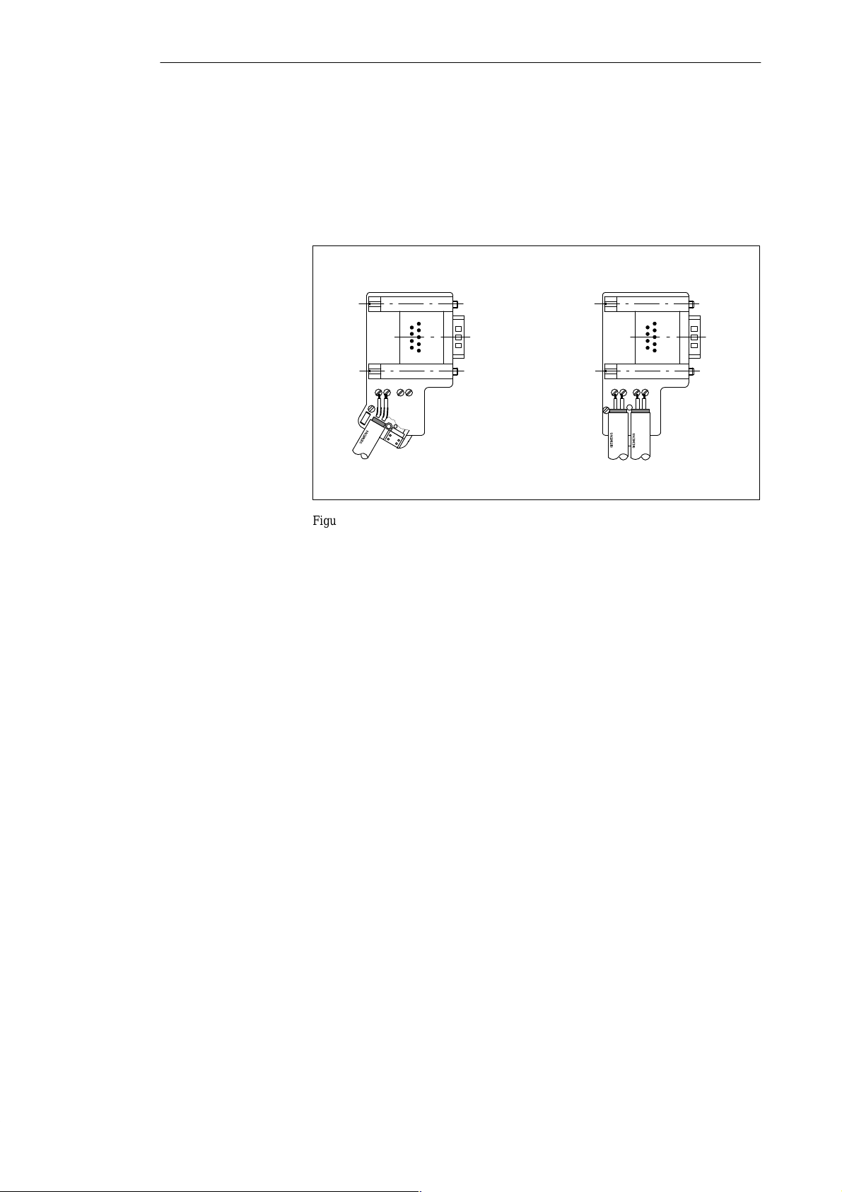
5. Fit the green and red wires into the screw terminal as shown in Figure
3-11.
Make sure that you always insert the same colored wire into the same
terminal on all connectors (for example the green wire into terminal A
and the red wire into terminal B, or vice-versa).
Bus cable connector for the first
and last stations on the bus
A B A B A B A B
1 The bus cable can be connected either to the right or left!
Figure 3-11 Fitting the Bus Connector (6ES7 972-0B.20 ...) to the LAN Cable
1
Bus cable connection for all
other stations on the bus
6. Screw down the hinged clamp again.
Make sure that the bare cable shield makes contact under the shield
clamp.
7. Secure the green and red wires in the screw terminal.
8. Close the cover of the bus connector.
3-16
9. Tighten the cover screw.
C7-621 / C7-621 AS-i Control Systems
C79000-G7076-C621-01
Page 61
3.5.3 Bus Connector 6ES7 972-0B.10-0XA0
➄
➂
➁
Configuring an MPI Network
Appearance
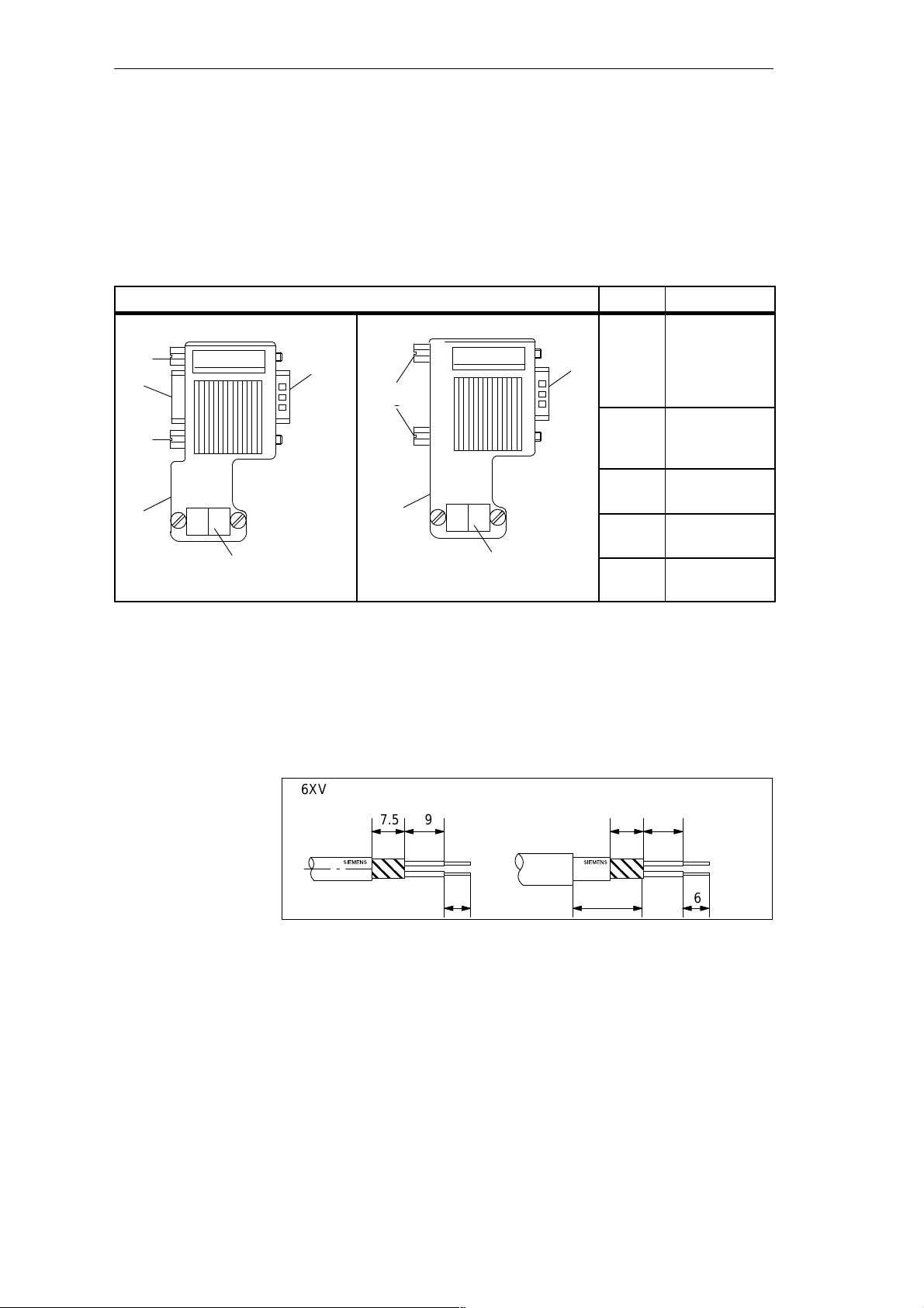
Table 3-6 Description and Functions of the Bus Connector 6ES7 972-0B.10-0XA0
With PG Interface
➄
T able 3-6 shows the bus connector 6ES7 972-0B.10-0XA0
Front View of the Bus Connector No. Function
Without PG Interface
➀
➀
➃
➄
➄
➂
➁
Preparing the
PROFIBUS LAN
Cable for the Bus
Connector
T o connect the bus connector 6ES7 972-0B.10-0XA0 to the PROFIBUS LAN
cable, follow the steps outlined below:
1. Cut the bus cable to the required length
2. Strip the insulation from the bus cable as shown in Figure 3-12.
➀
➁
➂
➃
➄
Connection to
the MPI,
PROFIBUS DP
interface (9-pin
sub D connector)
Connector for
the PROFIBUS
LAN cable
Terminating
resistor
Interface for
PG/OP
Screws for fixing
to the node
6XV1 830–0AH10/-3BH10 6XV1 830–3AH10
7.5 9
6
Figure 3-12 Preparing the LAN Cable for Connecting the Bus Connector
6ES7 972-0B.10-0XA0
7.5 9
16
6
3. Open the housing of the bus connector by undoing the screws in the
housing.
4. Remove the cover.
C7-621 / C7-621 AS-i Control Systems
C79000-G7076-C621-01
3-17
Page 62
Configuring an MPI Network
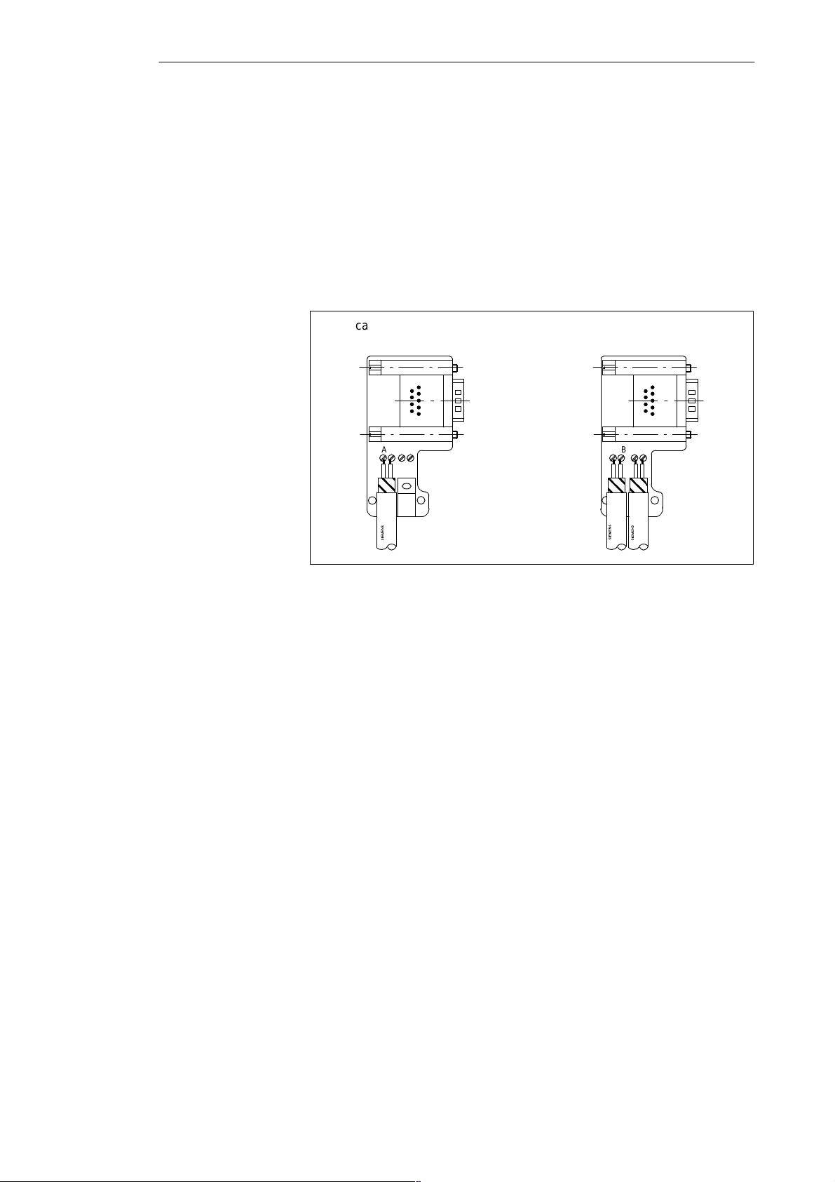
5. Fit the green and red wires into the screw terminal block as shown in
6. Press the cable sheath between the two clips. This fixes the cable in
7. Tighten the screw terminals for the green and red wires.
Figure 3-13.
Make sure that you always fit the same wires to the same terminal A or B
(for example always connect the green wire to terminal A and the red
wire to terminal B or vice-versa).
position.
Bus cable connection for first and
last node on the network.
A B A B
The LAN cable can be
connected either to the
right or left
Figure 3-13 Connecting the LAN Cable to the Bus Connector
6ES7 972-0B.10-0XA0
LAN cable connection for all
other nodes in the network.
A B A B
8. Close the housing again using the screws.
Make sure that the cable shield makes contact below the shield clamp.
3-18
C7-621 / C7-621 AS-i Control Systems
C79000-G7076-C621-01
Page 63
3.5.4 Connecting the Bus Connector to a Module
Configuring an MPI Network
Connecting the
Bus Connector
T o connect the bus connector, follow the steps outlined below:
1. Plug the bus connector into the module.
2. Screw the bus connector securely to the module.
3. If the bus connector with the order number 6ES7 ... is located at the start
or end of a segment, you must activate the terminating resistor (switch
setting “ON”) (see Figure 3-14 ).
Note
The bus connector 6ES7 972-0BA30-0XA0 does not have a terminating
resistor. You cannot plug in this bus connector at the start or end of a
segment.
Make sure that the stations on which the terminating resistor is located are
always turned on during startup and operation.
Terminating
resistor on
on
off
Terminating resistor
off
on
off
Removing the Bus
Connector
!
Figure 3-14 Bus Connector (6ES7 ... ): Terminating Resistor Activated and
Deactivated
You can remove the bus connector with a LAN cable connected through at
any time from the PROFIBUS DP interface without interrupting the data
exchange on the bus.
Warning
Disturbance of data exchange on the bus is possible!
A bus segment must always be terminated at both ends. This is, for example,
not the case if the power supply to the last slave with a bus connector is not
turned on. Since the bus connector takes its power from the station, this
would make the terminating resistor ineffective.
Make sure that the stations on which the terminating resistor is activated, are
always turned on.
C7-621 / C7-621 AS-i Control Systems
C79000-G7076-C621-01
3-19
Page 64

Configuring an MPI Network
3-20
C7-621 / C7-621 AS-i Control Systems
C79000-G7076-C621-01
Page 65
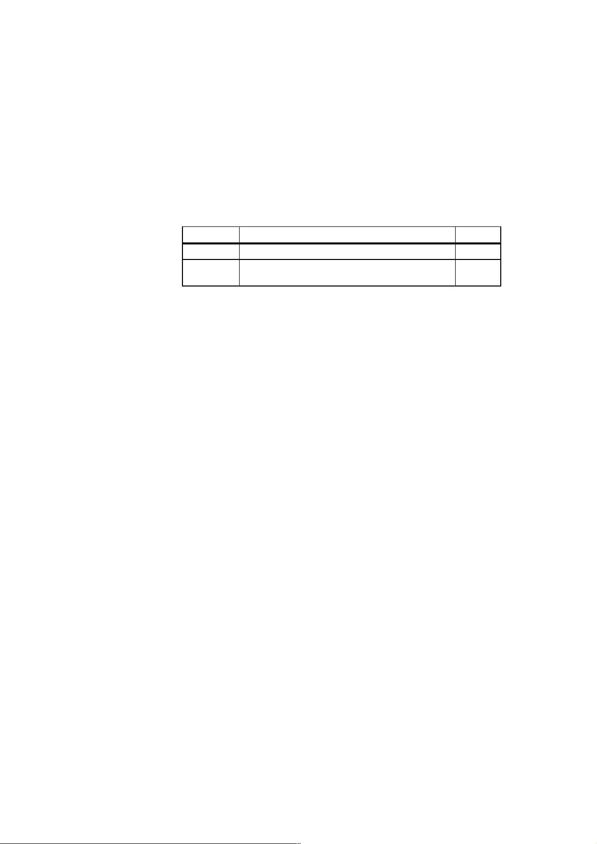
Connecting a Programming Device / PC to a C7
Chapter
Overview
4
Section Description Page
4.1 Connecting a Programming Device/PC to a C7 4-2
4.2 Connecting a Programming Device/PC to Several
Nodes
4-3
C7-621 / C7-621 AS-i Control Systems
C79000-G7076-C621-01
4-1
Page 66
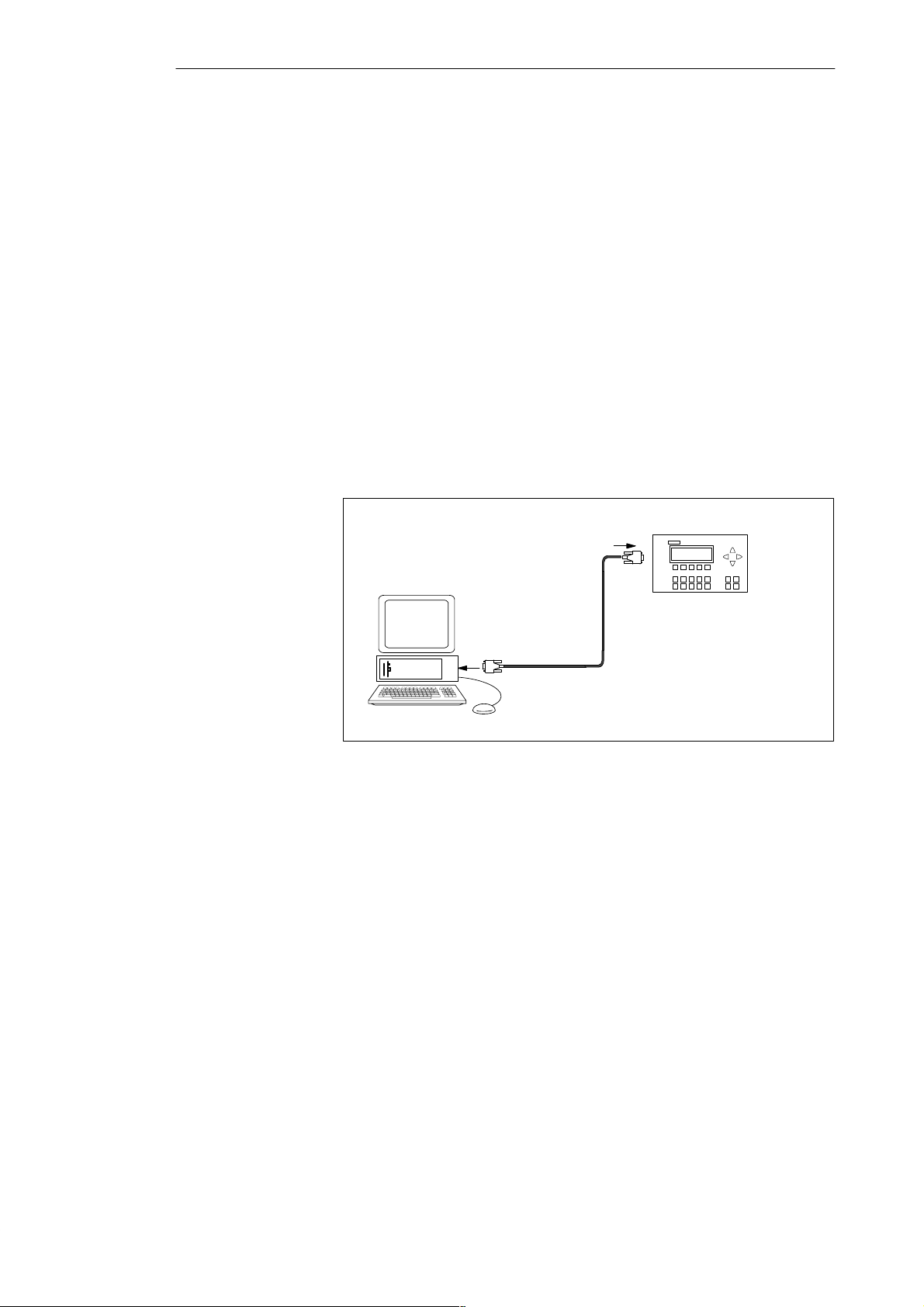
Connecting a Programming Device / PC to a C7
4.1 Connecting a Programming Device / PC to a C7
Possibilities
Cable Lengths
Connecting a
Programming
Device/PC to a C7
This chapter explains the ways in which you can connect a programming
device or PC to the C7 via the multipoint interface.
For information about the possible cable lengths, refer to Section 3.3.
You can connect a programming device or PC to the MPI port of the C7
using a preassembled PG cable.
As an alternative, you can use PROFIBUS LAN cable and bus connectors to
make your own connecting cable (see Section 3.5 ).
Figure 4-1 shows the components for connecting a programming device/PC
to a C7.
C7
PG cable
PG/PC
Figure 4-1 Connecting a Programming Device/PC to a C7
4-2
C7-621 / C7-621 AS-i Control Systems
C79000-G7076-C621-01
Page 67
Connecting a Programming Device / PC to a C7
4.2 Connecting a Programming Device/PC to Several Nodes
Possibilities
Two Installation
Options
This section explains how to connect a programming device or PC to more
than one node networked via the multipoint interface.
When you connect a programming device/PC to more than one node, you
must distinguish between two different types of connection:
S Fixed installation of the programming device/PC in the MPI network
S Programming device/PC connected only for installation and maintenance
work.
Depending on the network attachment, you connect the programming
device/PC with other nodes as follows (see also Section 3.2).
Network Attachment
Programming Device/PC installed
permanently in the network.
PG/PC attached for installation and
maintenance.
The programming device/PC is
included directly in the MPI
network.
The programming device/PC is
connected to a node via a tap line.
Connection
C7-621 / C7-621 AS-i Control Systems
C79000-G7076-C621-01
4-3
Page 68
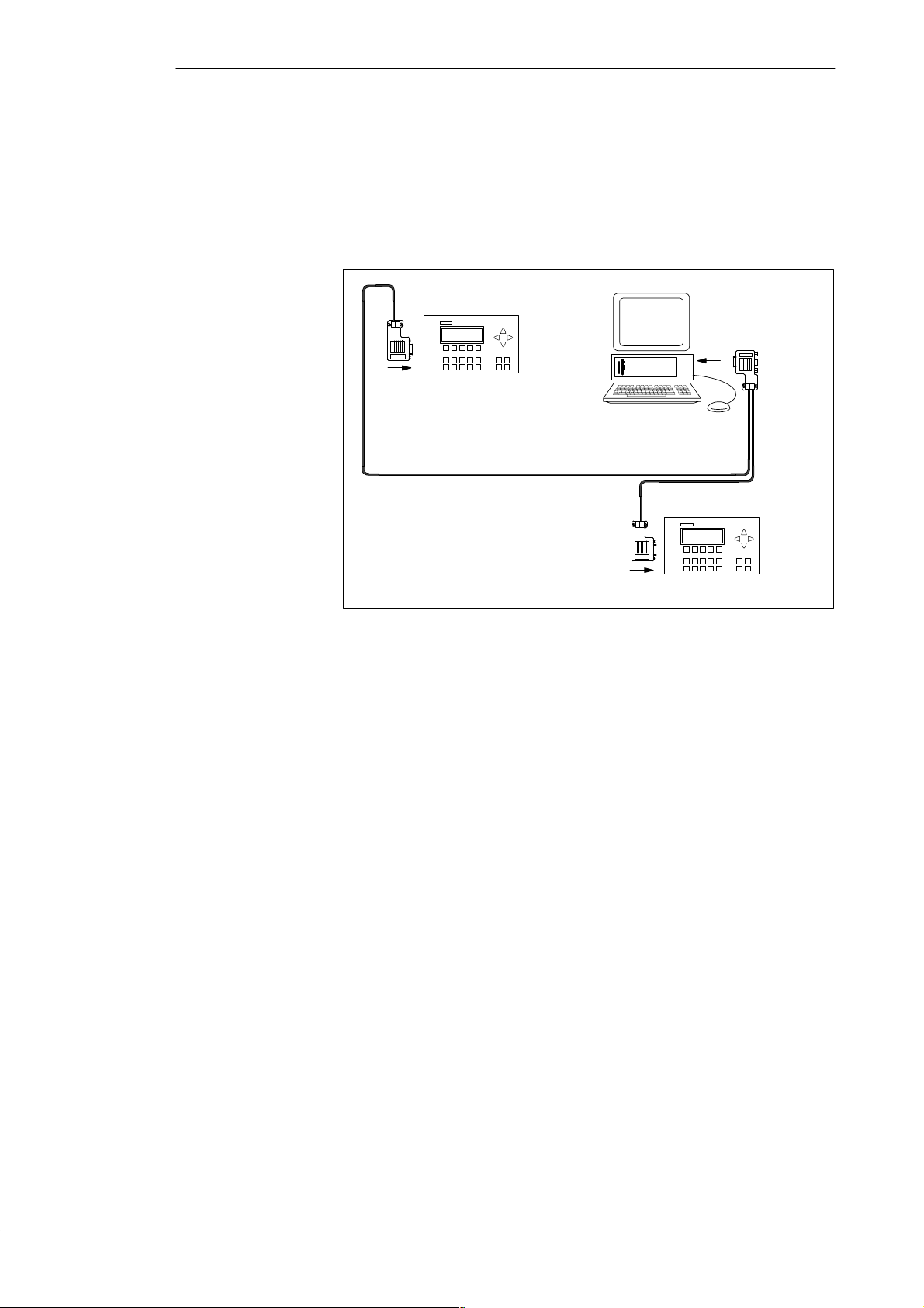
Connecting a Programming Device / PC to a C7
Permanently
Installed
Programming
Device/PC
You connect the permanently installed PG/PC in the MPI network to one or
more nodes of the MPI network according to the rules explained in Section
3.2.
Figure 4-2 shows a C7 network with two C7s. The two C7s are
interconnected using a PROFIBUS LAN cable.
C7
PG/PC
PROFIBUS LAN cable
PROFIBUS LAN cable
C7
Connecting a
Programming
Device/PC when
Service is
Required
Figure 4-2 Connecting a PG/PC to more than One C7
If there is no stationary programming device/PC, we recommend the
following procedure:
T o attach a programming device/PC to an MPI network with an “Unknown”
node address, it is advisable to set the following address on the service
programming device/PC:
S MPI address: 0
S Highest MPI address: 126.
Following this, use the STEP 7 function Hardware Configuration to find out
the highest MPI address in the MPI network and then set the highest MPI
address on the programming device/PC to the same value as that of the MPI
network.
4-4
C7-621 / C7-621 AS-i Control Systems
C79000-G7076-C621-01
Page 69
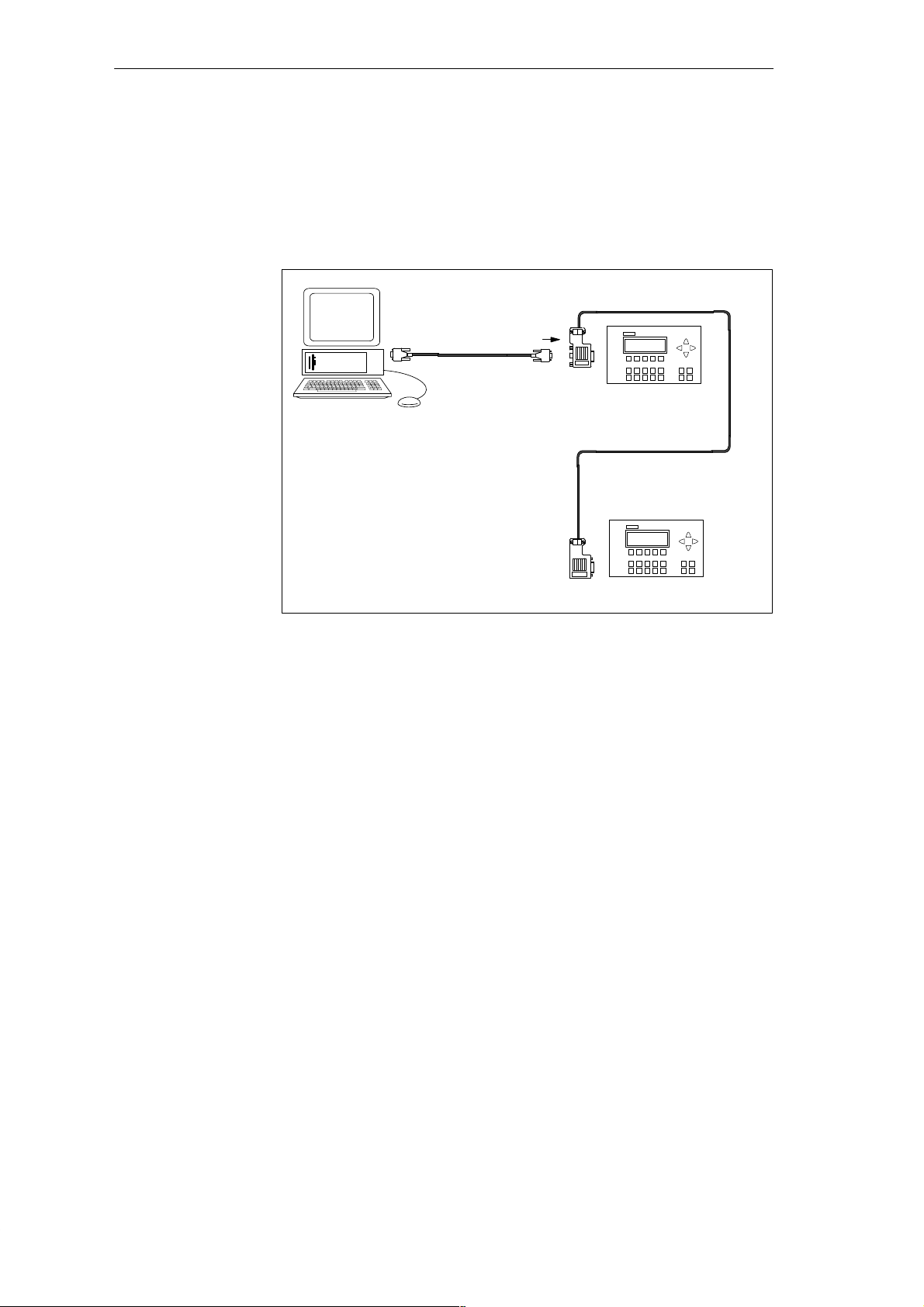
Connecting a Programming Device / PC to a C7
Programming
Device/PC for
Installation or
Maintenance
For installation or maintenance purposes, attach the programming device/PC
to a node of the MPI network using a tap line. The bus connector of this node
must have a PG interface (see also Section 3.5).
Figure 4-3 shows two networked C7s to which a programming device/PC is
connected.
PG cable = tap
line
C7
PG/PC
PROFIBUS LAN cable
C7
Figure 4-3 Attaching a Programming Device/PC to an MPI Network
C7-621 / C7-621 AS-i Control Systems
C79000-G7076-C621-01
4-5
Page 70
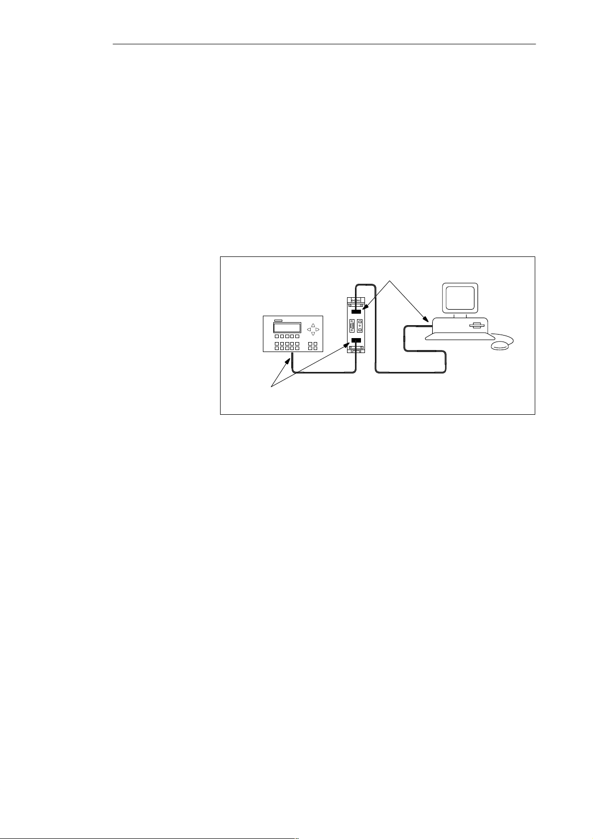
Connecting a Programming Device / PC to a C7
Attaching a
Programming
Device to an
Ungrounded Node
Connecting a
Grounded
Programming
Device to the MPI
If you install the nodes of a subnet or an S7-300 without grounding, only an
ungrounded programming device can be connected to the subnet or to the
S7-300.
You want to use ungrounded nodes. If the MPI is grounded on the PG, you
must include an RS 485 repeater between the nodes and the PG. The
ungrounded nodes must be connected to bus segment 2 if the PG is connected
to bus segment 1 (terminals A1 B1) or the programming device/OP interface
(see Chapter 7 in the reference manual Module Data).
Figure 4-4 shows the RS 485 repeater as an interface between a grounded and
an ungrounded node in an MPI subnet.
Bus segment 1
signals grounded
PG
C7
Bus segment 2
signals ungrounded
Figure 4-4 PG Connected to an Ungrounded S7-300
4-6
C7-621 / C7-621 AS-i Control Systems
C79000-G7076-C621-01
Page 71

Attaching a C7-621 AS-i
Note
The information in this chapter applies only to the C7-621 AS-i.
5
C7-621 / C7-621 AS-i Control Systems
C79000-G7076-C621-01
5-1
Page 72
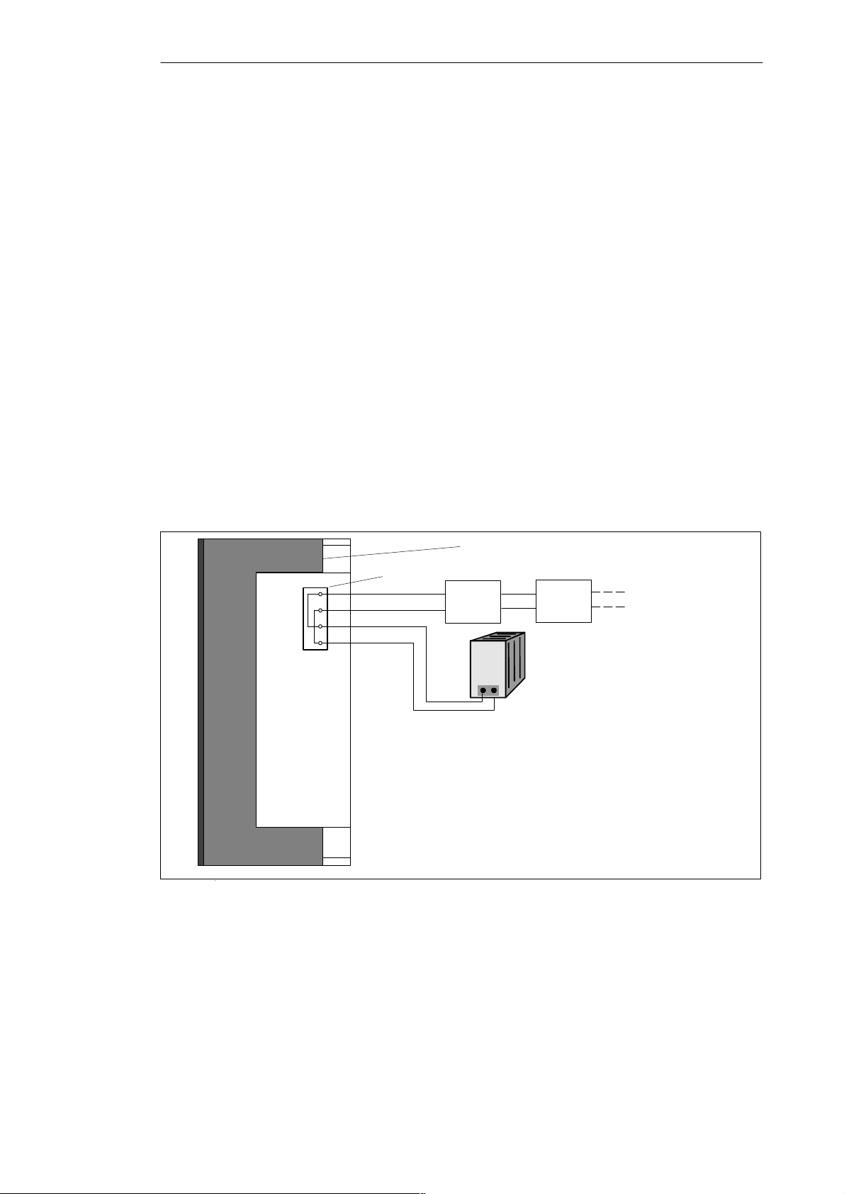
Attaching a C7-621 AS-i
5.1 AS-i Attachments
Properties
AS-i CP Power
Supply
AS-i Power Supply
Unit
Connections and
Block Diagram
AS-iAS-i+
AS-i-
AS-i+
The C7-621 AS-i has connectors for two AS-i cables that are connected
internally in the C7. The maximum load on the contacts is 4 A.
You can connect the following to the AS-i connectors:
S Actuators, sensors
S AS-i power supply unit
The AS-i CP is not supplied with power via the 24V DC input. The AS-i CP
must be supplied with power via terminals AS-i+ and AS-i-.
Connect the power supply unit either directly to the C7-621 AS-i or supply
power to the AS-i CP in the C7-621 AS-i by connecting the AS-i power
supply in the network with the actuators or sensors.
Figure 5-1 shows the connections and block diagram of the AS-i terminals.
View from the right side of the C7-621 AS-i
AS-i terminals
(blue)
(brown)
Sensor 1
Sensor 2
AS-i
power
supply
unit
Block diagram of
the AS-i terminals
Figure 5-1 Connections and Block Diagram of the AS-i Terminals
5-2
C7-621 / C7-621 AS-i Control Systems
C79000-G7076-C621-01
Page 73
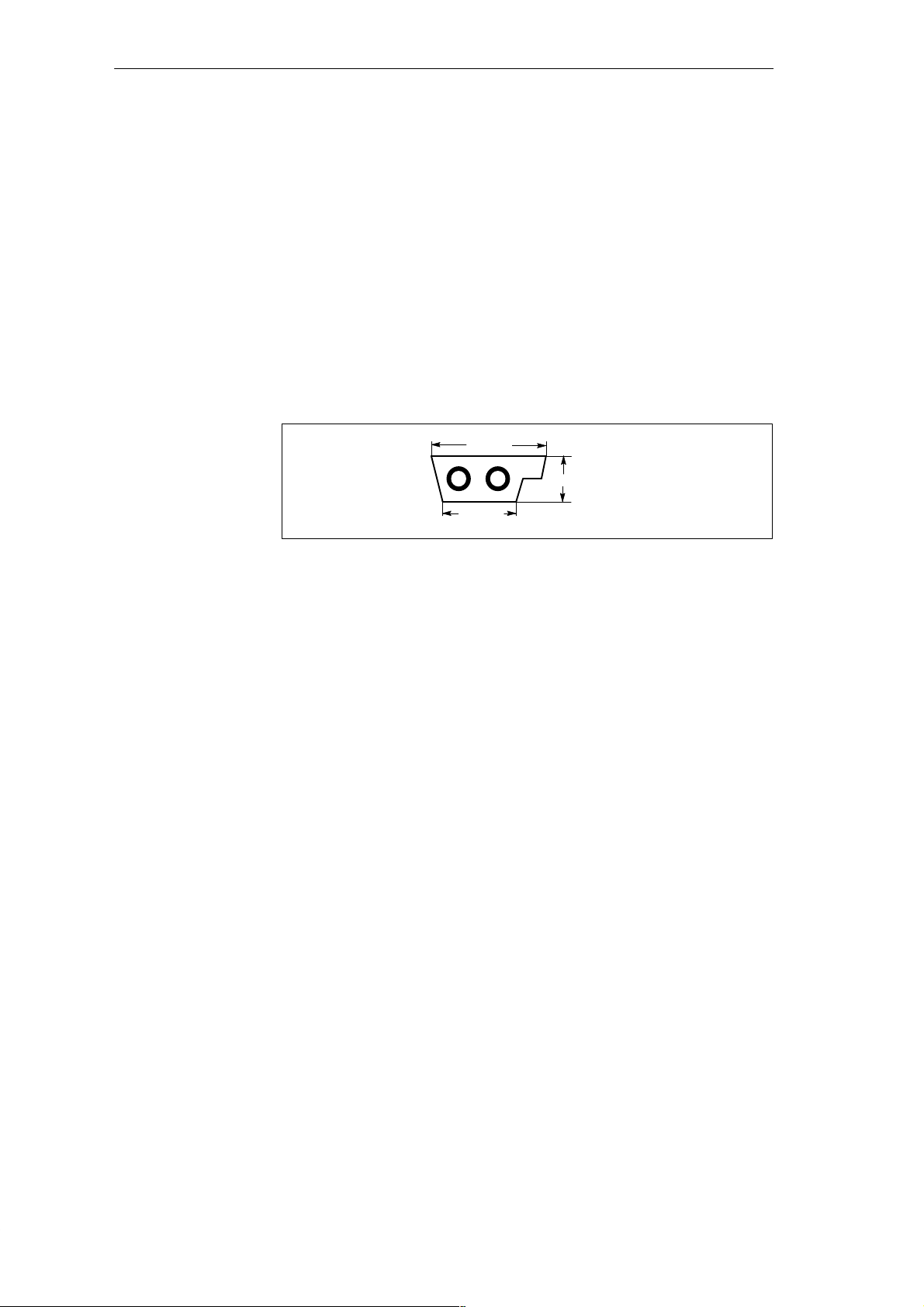
5.2 The AS-i Cable
Attaching a C7-621 AS-i
Overview
Attaching to the
AS-i Cable
The AS-i cable (a profile cable) allows simple and fast installation of an AS-i
system. The AS-i cable is a rubberized 2-wire cable (2 x 1.5 mm
2
). The
special profile of the cable prevents polarity reversal when connecting nodes.
Attachments are made to the AS-i cable using the penetration technique.
Contacts penetrate the rubberized jacket and make contact to the two cores.
This guarantees a low transition resistance and a reliable data connection.
The cable does not need to be cut, stripped or screwed. T o attach to the
network, there are coupling modules that use the penetration technique.
10 mm
4 mm
6,5 mm
Figure 5-2 Cross-Section of the Cable
The jacket of the AS-i cable is rubber. If it becomes necessary to move
modules after they have been connected to the AS-i cable, this can be done
without any problem. The AS-i cable is self-healing. This means that the
holes made by the contacts penetrating the jacket close automatically and
re-establish degree of protection IP67. When the cable is installed in an AS-i
module, the cable seals the cable inlets. This allows degree of protection
IP67 to be achieved.
Using Other 2-Wire
Cables
Apart from the special AS-i cable, any 2-wire cable with a cross-section of
2 x 1.5 mm
change from the special AS-i cable to another cable (for example a standard
round cable), there is a special module without integrated electronics
available (transition from the AS-i cable to four M12 terminals and transition
from the AS-i cable to one M12 terminal).
Operation and
Display Elements
C7-621 / C7-621 AS-i Control Systems
C79000-G7076-C621-01
How to use the AS-i CP and the meaning of the displays on the AS-i module
are described in Volume 2 Section 6.4.
2
can be used. Shielding or twisting is not necessary. For the
5-3
Page 74

Attaching a C7-621 AS-i
5-4
C7-621 / C7-621 AS-i Control Systems
C79000-G7076-C621-01
Page 75
C7-621 Digital I/Os
6
Chapter
Overview
Section Description Page
6.1 Digital Inputs 6-2
6.2 Digital Outputs 6-4
6.3 Status Displays of the DI/DO 6-7
Note
The information this chapter applies only to the C7-621. The C7-621 AS-i
does not have digital I/Os.
C7-621 / C7-621 AS-i Control Systems
C79000-G7076-C621-01
6-1
Page 76
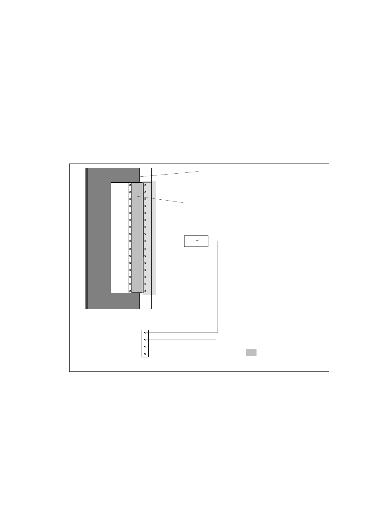
C7-621 Digital I/Os
6.1 Digital Inputs
Characteristics
Terminals and
Block Diagram
The digital inputs have the following characteristics:
S 16 inputs, non-floating
S Rated input voltage: 24V DC
S Suitable, for example, for switches and 2-wire proximity switches
(BEROs)
Figure 6-1 shows the terminals and block diagram of the digital inputs.
Bottom view of the C7-621
0.0
0.1
0.2
0.3
0.4
0.5
0.6
0.7
1.0
1.1
1.2
1.3
1.4
1.5
1.6
1.7
Block diagram of
an input
Digital inputs
Pin name
L+
M
NC
NC
Input DC 24V
Figure 6-1 Terminals and Block Diagram of the Digital Inputs
6-2
These shaded sections
are irrelevant for this
example.
C7-621 / C7-621 AS-i Control Systems
C79000-G7076-C621-01
Page 77
C7-621 Digital I/Os
Digital Input
The following table shows the technical data of the digital inputs of the C7
CPU.
Module-Specific Data
Number of inputs 16
Cable length
S Unshielded max. 600 m
Voltages, Currents, Potentials
Rated load voltage L+
S Re verse polarity
protection
Number of simultaneously
accessible inputs
Floating no
DC 24 V
yes
16
Status, Interrupt, Diagnostics
Interrupts no
Diagnostic functions no
Data for Selecting a Sensor
Input voltage
S Rated value
S For signal “1”
S For signal“0”
Input current
DC 24 V
11 to 30 V
-3 to +5 V
S For signal “1” Typically 7 mA
Input delay
S From “0” to “1”
S From “1” to “0”
Input characteristics Complying with IEC
Connection of 2-wire BEROs
S Permitted closed-circuit
current
1.2 to 4.8 ms
1.2 to 4.8 ms
1131, Type 2
Possible
max. 2 mA
C7-621 / C7-621 AS-i Control Systems
C79000-G7076-C621-01
6-3
Page 78

C7-621 Digital I/Os
6.2 Digital Outputs
Properties
Note
The digital outputs have the following properties:
S 16 outputs, non-floating
S Output current 0.5 A
S Rated load voltage: 24V DC
S Suitable, for example, for solenoid valves and DC contactors.
When the power supply is turned on, the digital output applies a pulse to the
outputs. Within the permitted output current range, a pulse can be
approximately 50 s long.
6-4
C7-621 / C7-621 AS-i Control Systems
C79000-G7076-C621-01
Page 79
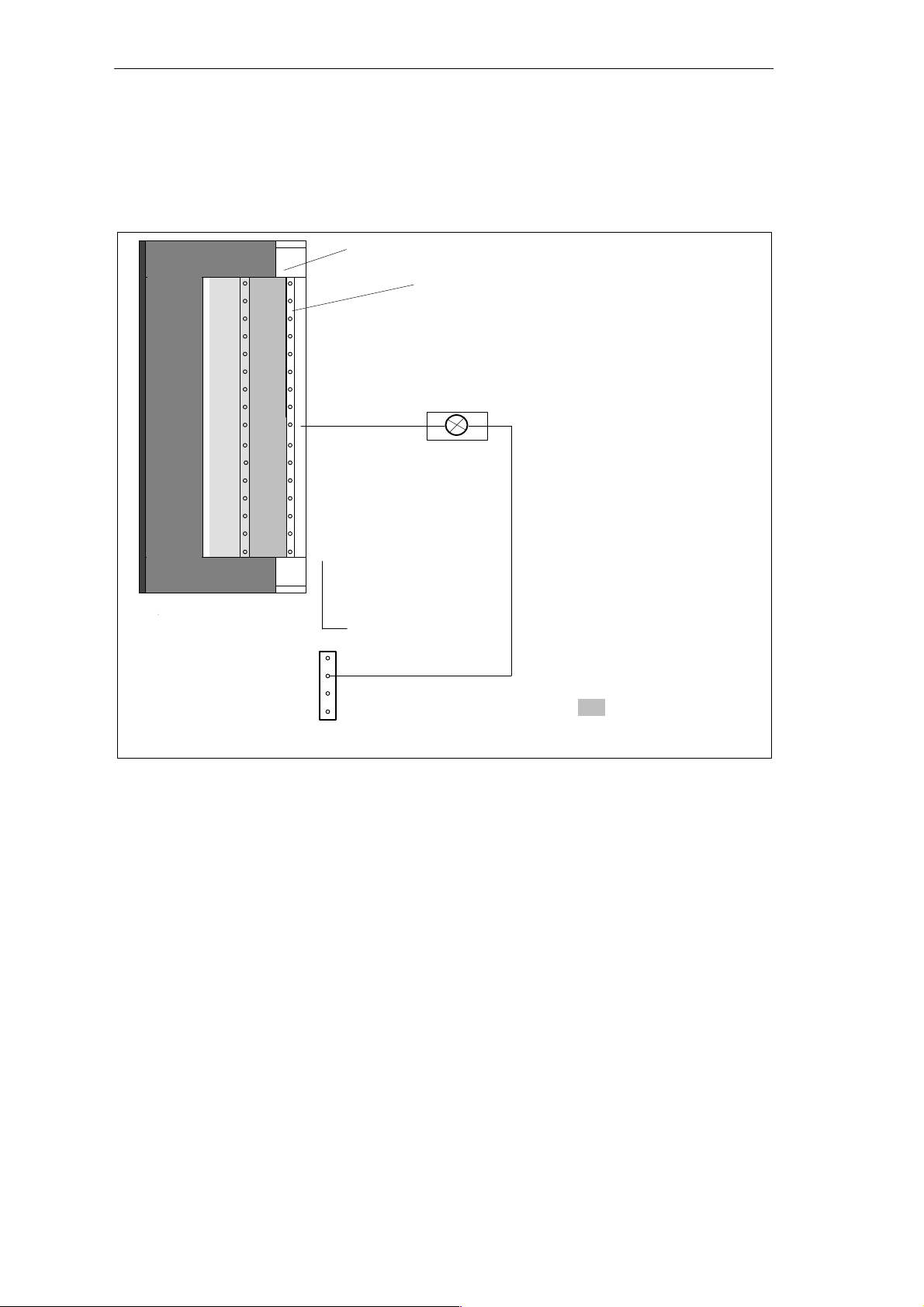
C7-621 Digital I/Os
Terminals and
Block Diagram
Figure 6-2 shows the terminals and block diagram of the digital outputs.
The following page has more detailed technical data about the digital
outputs.
Bottom view of the C7-621
0.0
0.1
0.2
0.3
0.4
0.5
0.6
0.7
1.0
1.1
1.2
1.3
1.4
1.5
1.6
1.7
Digital outputs
Block diagram of
an output
Pin name
L+
M
NC
NC
Input DC 24V
Figure 6-2 Terminals and Block Diagram of the Digital Outputs
Shaded sections are
irrelevant for this
example.
C7-621 / C7-621 AS-i Control Systems
C79000-G7076-C621-01
6-5
Page 80
C7-621 Digital I/Os
Digital Outputs
The following table shows the technical data of the digital outputs of the C7
CPU.
Module-Specific Data
Number of outputs 16
Cable length
S Unshielded max. 600 m
Voltages, Currents, Potential
Rated load voltage L+
S Reverse polarity protection
Total current of the outputs
(per group: 0.0 to 0.7 or
1.0 to 1.7)
S Up to 20 °C
S Up to 45 °C
Floating no
Status, Interrupts, Diagnostics
Interrupts no
Diagnostic functions no
24 V DC, 0.5 A
no
max. 4 A
max. 2 A
Data for Selecting an Actuator
Output voltage
S At signal “1” min. L+ (- 0.8 V)
Output current
S For signal “1”
Rated value
Permitted range
S For signal “0”
(residual current)
Load resistance range 48 W to 4 kW
Lamp load max. 5 W
Parallel connection of 2
outputs
S For redundant activation of
a load
S For increased power
Activation of a digital input Possible
Switching frequency
S With ohmic load
S With inductive load to IEC
947-5-1, DC 13
S With lamp load
0.5 A
5 mA to 0.6 A
max. 0.5 mA
Possible, only outputs
of the same group
Not possible
max. 100 Hz
max. 0.5 Hz
max. 100 Hz
Limitation (internal) of the
inductive cut-off voltage
Short circuit protection of the
output
S Switching threshold
Typically L+ (- 48 V)
Yes, clocked
electronically
Typically 1 A
6-6
C7-621 / C7-621 AS-i Control Systems
C79000-G7076-C621-01
Page 81
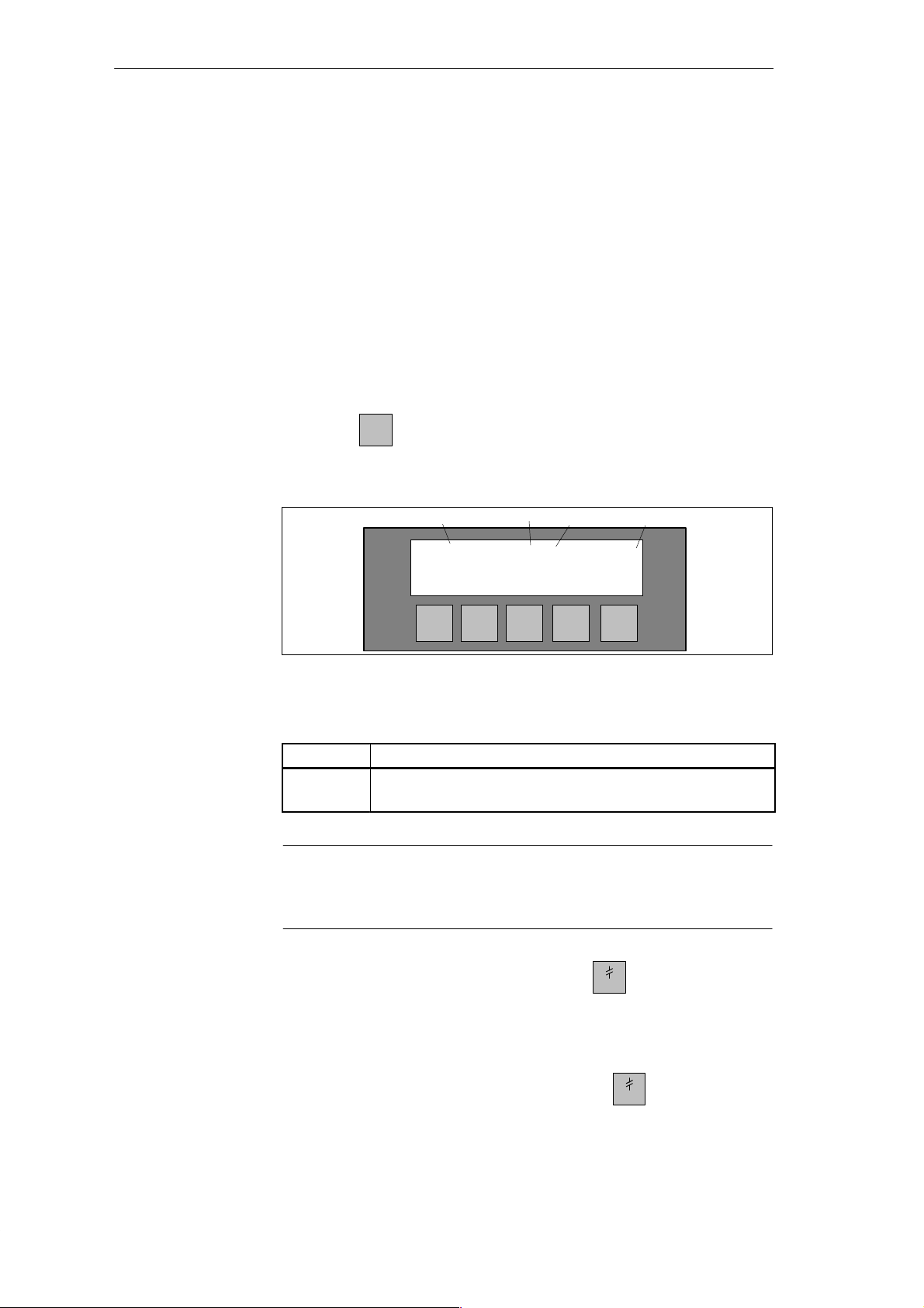
6.3 Status Displays of the DI/DO
C7-621 Digital I/Os
Overview
Selecting the
DI/DO Status
Display
The status of the digital I/Os can be displayed with one of the C7 system
functions. The values are read as direct process values (PIW) of the DI and as
the process image (QW) of the DO C7 I/Os and displayed in the format BIN.
It is not possible to modify the display.
In the STOP mode, the real process status for DO = 0. The displayed process
image can deviate from this; the displayed image represents the last image
set by the control program.
You can select the DI/DO status display without an operator password. The
DI/DO status display can be selected in the system functions menu by
pressing the
key.
The following data are displayed:
Bit 0.7 Bit 0.0 Bit 1.7 Bit 1.0
DI:11101110 00001010
= Anwahl der
DO:10101010 11010001
Quitting the DI/DO
Display
Quitting the
System Functions
Menu
Figure 6-3 Example of a Status Display on a C7-621
Table 6-1 Explanation of the DI/DO Status Display in Figure 6-3
Display
1
0
DI/DO set
DI/DO reset
Explanation
Note
The values of the DI/DO are read in at one second intervals and displayed.
Changes taking place between these two points are not displayed.
You quit the DI/DO status display by pressing the
key. If you do not
quit explicitly, the C7-621 changes automatically to the C7-621 idle message
after approximately one minute.
You quit the system functions menu by pressing the
key.
C7-621 / C7-621 AS-i Control Systems
C79000-G7076-C621-01
6-7
Page 82

C7-621 Digital I/Os
6-8
C7-621 / C7-621 AS-i Control Systems
C79000-G7076-C621-01
Page 83
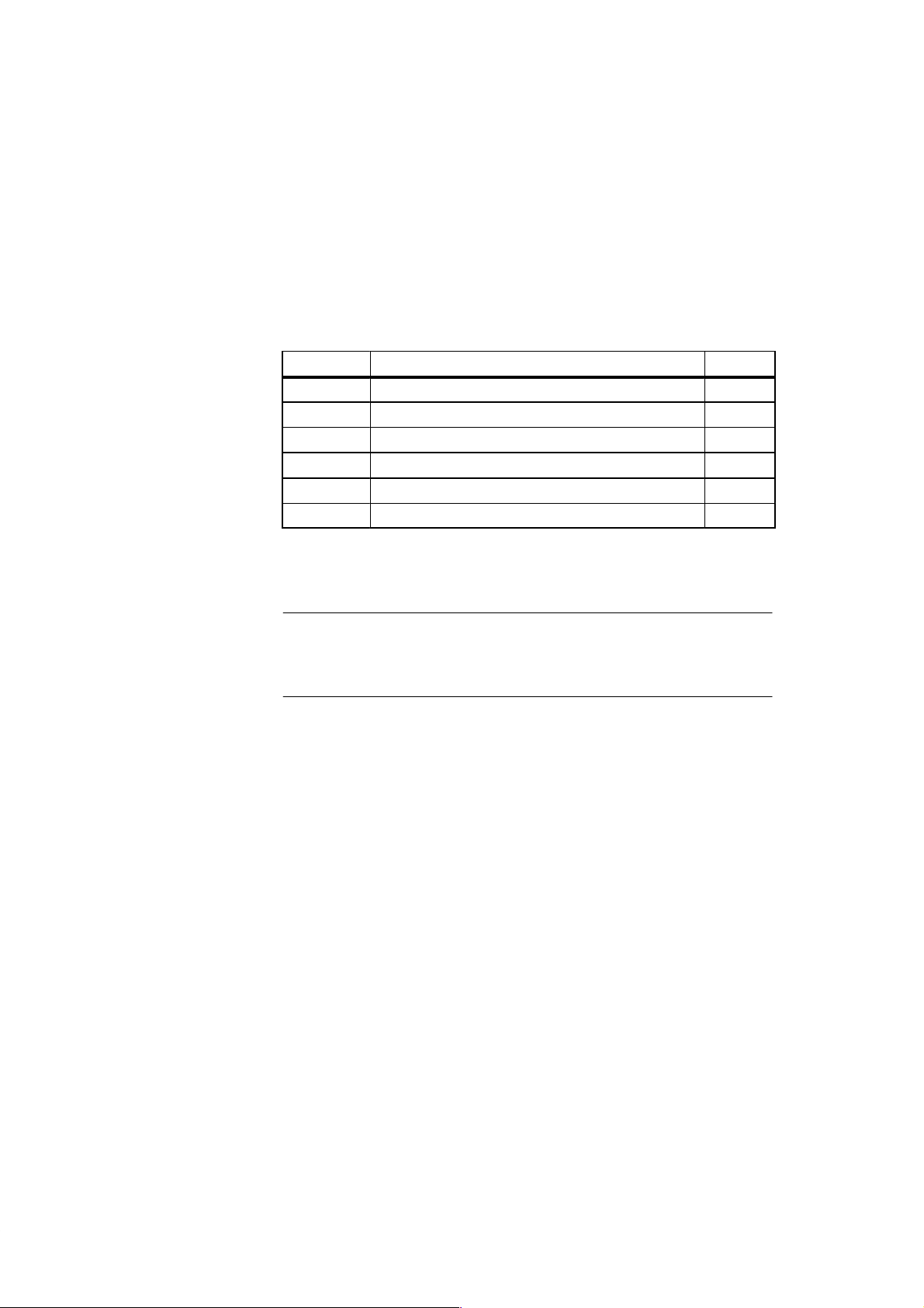
C7-621 Analog I/Os
7
Chapter
Overview
Ungrounded
Configuration
Section Description Page
7.1 Connecting Sensors to Analog Inputs 7-2
7.1.1 Connecting Voltage and Current Sensors 7-5
7.2 Connecting Loads/Actuators to the Analog Output 7-7
7.3 Analog Input 7-10
7.3.1 Properties and T echnical Data of the Analog Input 7-11
7.4 Analog Output 7-15
It is not possible to include the C7 in an ungrounded configuration.
Note
The information in this section applies only to the C7-621. The C7-621 AS-i
does not have analog I/Os.
C7-621 / C7-621 AS-i Control Systems
C79000-G7076-C621-01
7-1
Page 84

C7-621 Analog I/Os
7.1 Connecting Sensors to Analog Inputs
Overview
Cables for Analog
Signals
Connecting
Sensors to Analog
Inputs
Depending on the type of measurement, you can connect various sensors to
the analog inputs:
S Voltage sensors
S Current sensors
This section describes how to connect sensors and points to note when
connecting them.
You should use shielded, twisted pair cables for analog signals. This reduces
the effects of noise. The shield of the analog cables should be grounded at
both ends. If there are potential differences between the ends of the cable, an
equipotential current can flow through the shield and cause disturbances to
the analog signals. In this case you should only ground the cable at one end.
A potential difference U
cable AIx-M of the input channels and the reference point of the measuring
circuit M. This potential difference must, however, not exceed the permitted
limit value (see technical data). If it is possible that the permitted value for
U
will be exceeded or if you cannot measure the potential difference
CM
exactly , you must connect AIx-M with M. This also applies to unused inputs.
(common mode voltage) may occur between the
CM
Abbreviations
Isolated Sensors
The following abbreviations are used in Figures 7-1 to 7-4:
AIx-X: Measuring cable AIx-U or AIx-I
AIx-M: Reference potential of the measuring cable
M: Chassis connection of C7-621 and
Reference potential of the analog measuring circuit
(functional earth
U
: Potential difference between inputs and M
CM
)
Isolated sensors are not connected to the local ground. They can be operated
as floating sensors. Due to the local conditions or noise, potential differences
U
(static or dynamic) can occur between the measuring cables AIx-M of
CM
the input channels and the reference point of the measuring circuit M. This
potential difference must, however, not exceed the maximum permitted
value. If it is possible that the value will exceed the maximum permitted
value for U
or if you cannot measure the potential difference exactly, you
CM
must connect AIx-M with M.
7-2
C7-621 / C7-621 AS-i Control Systems
C79000-G7076-C621-01
Page 85
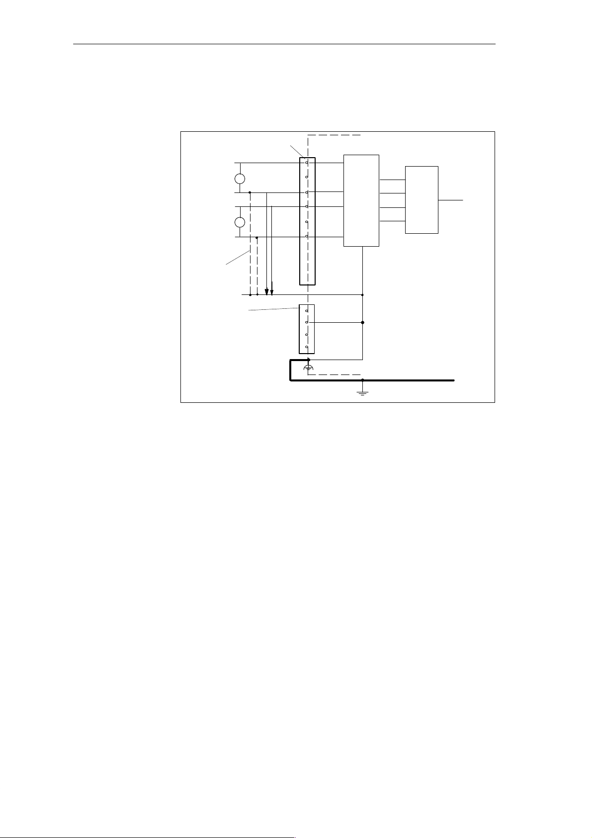
C7-621 Analog I/Os
Figure 7-1 shows the connection of isolated sensors to a non-floating analog
input.
Analog inputs
+
U
Isolated
sensors
Recommended
connection
Input 24V DC
Figure 7-1 Connection of Isolated Sensors to a Non-Floating Analog Input
-
+
U
-
AI1-U
AI1-M
AI2-U
AI2-M
.
.
CM
.
U
L+
M
NC
NC
Functional ground
M
C7-621
ADC
Logic
C7-CPU
Grounding bar
Non-Isolated
Sensors
Non-isolated sensors are connected to ground locally. Due to local conditions
or noise, potential differences (static or dynamic) can occur between the
locally distributed measuring points. T o avoid these potential differences, you
should install equipotential bonding cables between the measuring points.
Potential differences U
measuring cables AIx-M of the input channels and the reference point of the
measuring circuit M. This potential difference must not exceed the maximum
permitted value. If it is possible that this will exceed the maximum permitted
value for U
AIx-M must be connected to M.
C7-621 / C7-621 AS-i Control Systems
C79000-G7076-C621-01
(static or dynamic) can also occur between the
CM
or if you cannot measure the potential difference exactly,
CM
7-3
Page 86
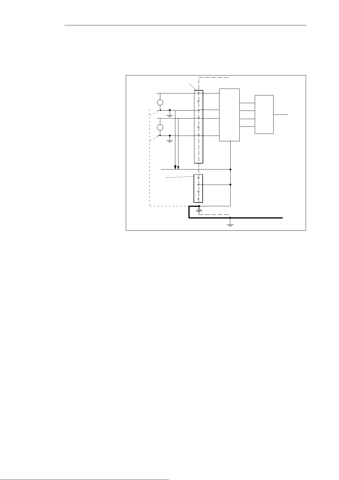
C7-621 Analog I/Os
Figure 7-2 shows the connection of non-isolated sensors to a floating analog
input module.
Isolated
sensor
Analog inputs
+
U
+
AI1-U
AI1-M
AI2-U
ADC
C7-621
Logic
U
AI2-M
.
.
CM
.
U
M
Input 24V DC
L+
M
NC
NC
Equipotential
bonding cable
Functional earth
Grounding bar
Figure 7-2 Connecting Non-Isolated Sensors to a Floating Analog Input
C7-CPU
7-4
C7-621 / C7-621 AS-i Control Systems
C79000-G7076-C621-01
Page 87
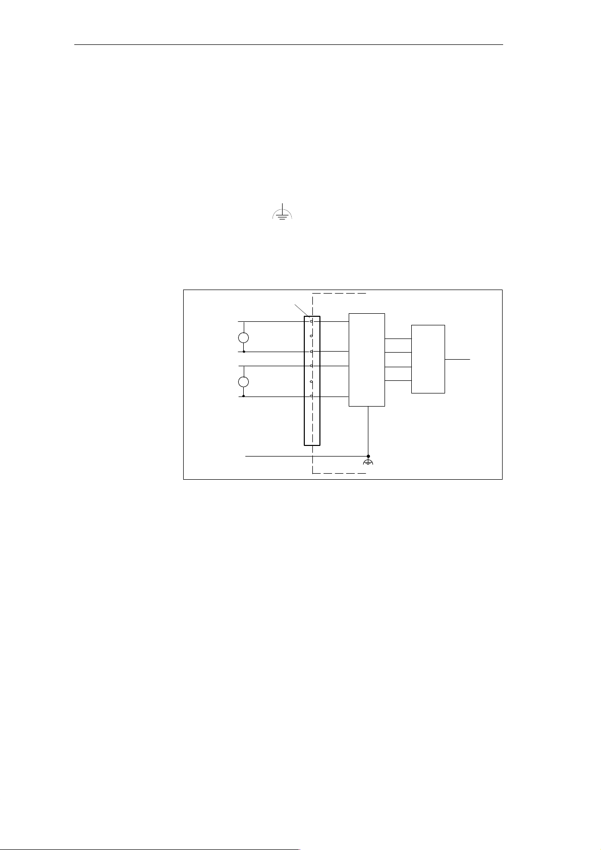
7.1.1 Connecting Voltage and Current Sensors
C7-621 Analog I/Os
Abbreviations
Connecting
Voltage Sensors
The abbreviations in Figures 7-3 to 7-4 have the following meaning:
AIx-X: Measuring cable AIx-I or AIx-U
AIx-M: Measuring cable reference potential
M: Reference potential of the analog measuring circuit (functional
ground
)
Figure 7-3 shows the connection of voltage sensors to a non-floating analog
input.
ADC
C7-621
Logic
C7-CPU
Analog inputs
+
U
-
+
U
-
AI1-U
AI1-M
AI2-U
AI2-M
.
.
.
M
Figure 7-3 Connecting Non-Isolated Sensors to a Non-Floating Analog Input
Functional ground
C7-621 / C7-621 AS-i Control Systems
C79000-G7076-C621-01
7-5
Page 88
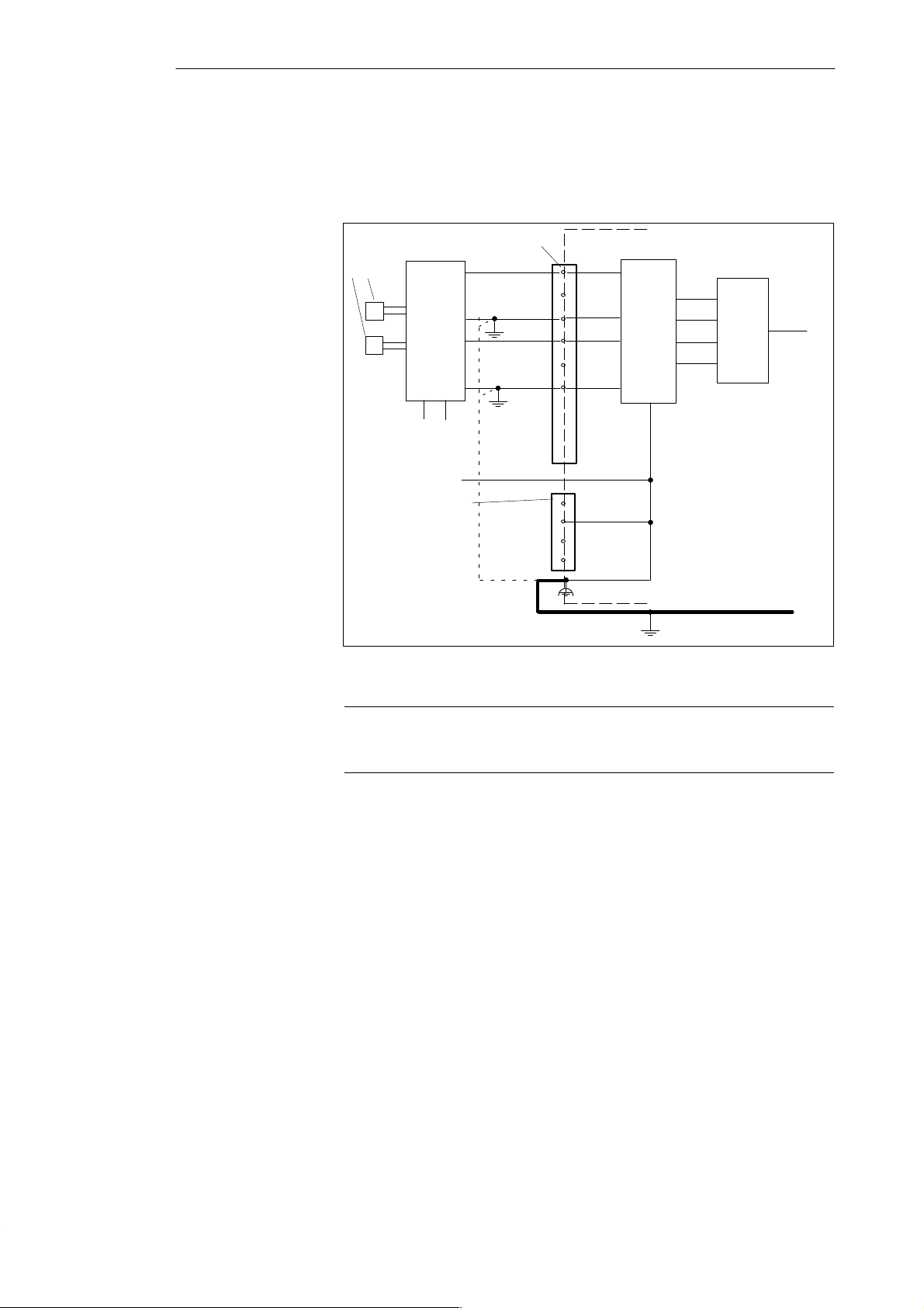
C7-621 Analog I/Os
Connecting
Sensors as 4-Wire
Transducers
4-wire transducers have a separate power supply UH. Figure 7-4 shows the
connection of sensors as 4-wire measuring transducers to a non-floating
analog input.
Sensor
e.g. pressure
meas.
P
P
Input 24V DC
Analog inputs
+
+
-
transducer
4-wire
U
H
AI1-U
AI1-M
AI2-U
AI2-M
.
.
.
M
L+
M
NC
NC
ADC
C7-621
Logic
C7-CPU
Functional ground
Figure 7-4 Connecting 4-Wire Transducers to a Non-Floating Analog Input
Grounding bar
Note
2-wire transducers cannot be operated with the C7 units.
7-6
C7-621 / C7-621 AS-i Control Systems
C79000-G7076-C621-01
Page 89

7.2 Connecting Loads/Actuators to the Analog Output
C7-621 Analog I/Os
Overview
Cables for Analog
Signals
Abbreviations
With the analog output, you can supply loads/actuators with current or
voltage.
You should use shielded, twisted pair cables for analog signals. This reduces
the effects of noise. The shield of the analog cables should be grounded at
both ends. If there are potential differences between the ends of the cable, an
equipotential current can flow through the shield and cause disturbances to
the analog signals. In this case you should only ground the cable at one end.
The abbreviations used in Figures 7-5 to 7-6 have the following meaning:
AO-I: Analog output current
AO-U: Analog output voltage
R
: Load/actuator
L
AO-M : Chassis connection (reference potential of the analog output)
L+: Power supply connection 24 V DC
M: Chassis connection of the C7
Figures 7-5 to 7-6 show how the loads/actuators must be connected to the
current or voltage outputs of the analog output module.
C7-621 / C7-621 AS-i Control Systems
C79000-G7076-C621-01
7-7
Page 90
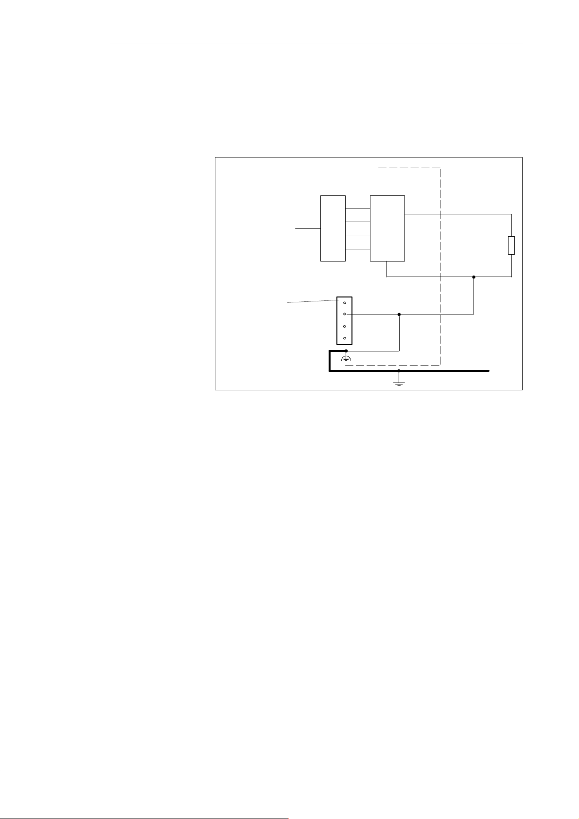
C7-621 Analog I/Os
Connecting Loads
to a Current
Output
T o connect a load to a current output, you must connect AO-M to a AO-I and
the reference point of the analog circuit.
Figure 7-5 shows the connection of loads to a current output of a non-floating
analog output module.
C7-621
AO-I
C7-CPU
Input 24V DC
Logic
L+
M
NC
NC
DAC
M
Functional ground
AO-M
R
L
Figure 7-5 Connecting Loads to a Current Output of a Non-Floating Analog Output
7-8
C7-621 / C7-621 AS-i Control Systems
C79000-G7076-C621-01
Page 91
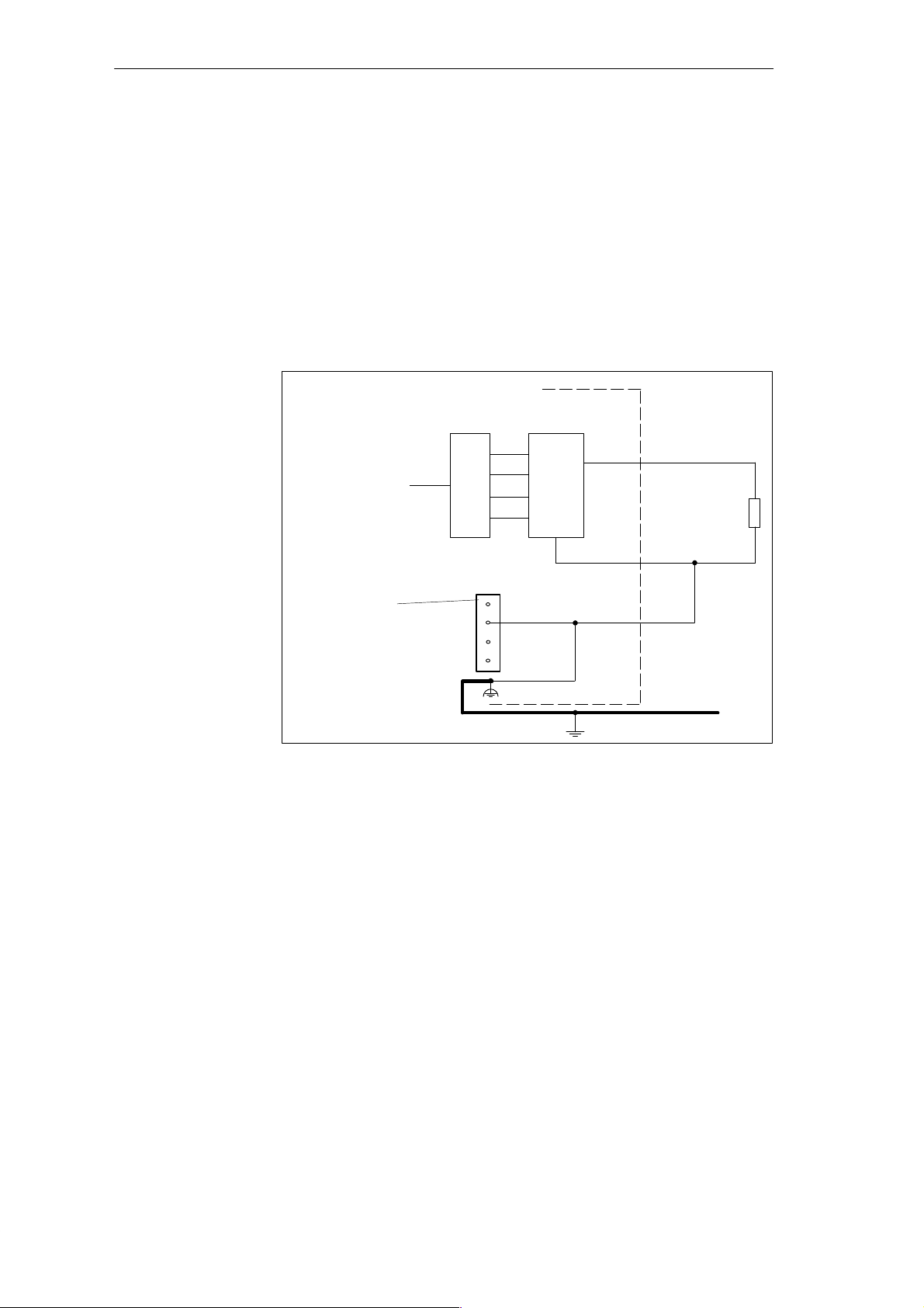
C7-621 Analog I/Os
Connecting Loads
to a Voltage
Output
2-Wire Connection
Connecting loads to a single voltage output is only possible with a 2-wire
connection.
The connection of loads to a voltage output using a 2-wire connection is
made at the analog output AO-U and the reference point of the measuring
circuit AO-M.
Figure 7-6 shows the connection of loads to a voltage output of a
non-floating analog output module with a 2-wire connection.
C7-621
AO-U
C7-CPU
Logic
DAC
M
AO-M
R
L
Input 24V DC
Figure 7-6 Connection of Loads to a Voltage Output of a Non-Floating Analog
Output Module
L+
M
NC
NC
Functional ground
C7-621 / C7-621 AS-i Control Systems
C79000-G7076-C621-01
7-9
Page 92

C7-621 Analog I/Os
7.3 Analog Input
Contents
Selectable Types
of Measurement
Measurement
Ranges
Measurement
Ranges for 4-Wire
Measuring
Transducers
This section explains the following:
S The properties of the analog input module
S The technical data of the analog input module
You will learn the following:
S How to install the analog input module
S Which measuring ranges are provided by the analog input module
The following measurement types are possible on the analog input module:
S Voltage measurement
S Current measurement
The measurement ranges are as follows:
S Voltage: "10V
S Current: "20mA
The measuring ranges for current measurement with 4-wire measuring
transducers are as follows:
S "20mA
7-10
C7-621 / C7-621 AS-i Control Systems
C79000-G7076-C621-01
Page 93

C7-621 Analog I/Os
7.3.1 Properties and Technical Data of the Analog Input Module
Properties
The analog input module has the following properties:
S 4 inputs
S Measured value resolution
– 12 bits including sign
S Measurement type (selected by wiring):
– Voltage
– Current
S Measuring range selected per input
S Non-floating
C7-621 / C7-621 AS-i Control Systems
C79000-G7076-C621-01
7-11
Page 94
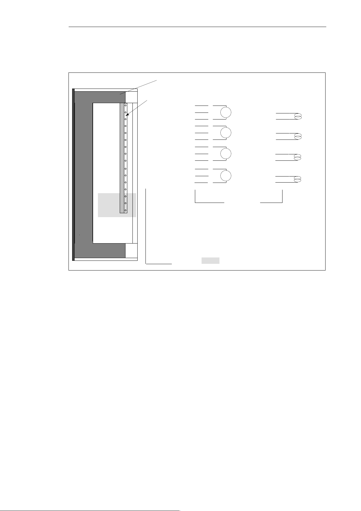
C7-621 Analog I/Os
T erminal Diagram
Figure 7-7 shows the terminal diagram of the analog inputs
View from the right of the C7-621
Analog inputs
AI1-U
AI1-I
AI1-M
AI2-U
AI2-I
AI2-M
AI3-U
AI3-I
AI3-M
AI4-U
AI4-I
AI4-M
Voltage measurement
1
2
3
4
5
6
7
8
9
10
11
12
V
V
V
V
Connection
Current measurement
1
2
3
4
5
6
7
8
9
10
11
12
Pin name
Figure 7-7 Terminal Diagram of the Analog Inputs
Analog Addresses
For more information about analog addresses, refer to Volume 2, Chapter 4.
These shaded sections are irrelevant
for this example.
7-12
C7-621 / C7-621 AS-i Control Systems
C79000-G7076-C621-01
Page 95
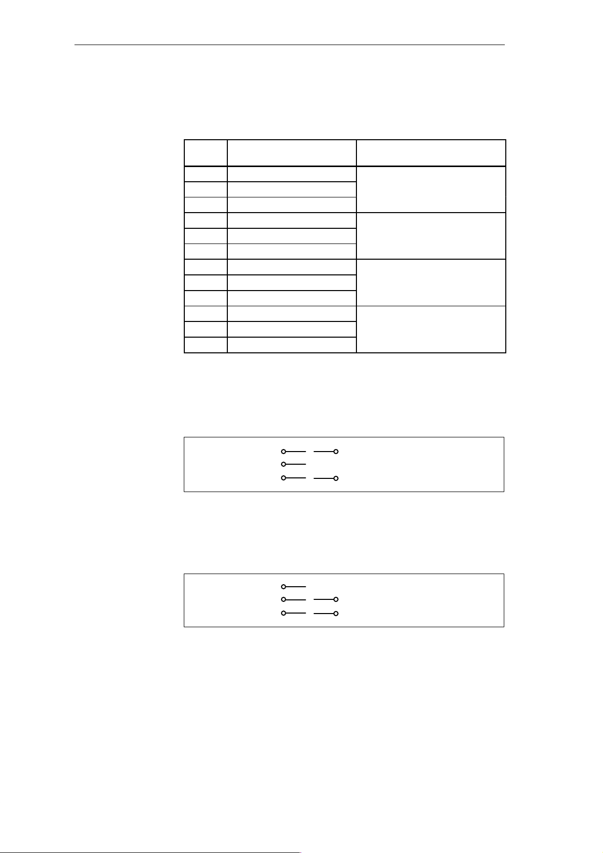
C7-621 Analog I/Os
Channels
Three pins are grouped together to form a channel.
Table 7-1 Channels of the Analog Input Module
Pin
Name
AI1-U Voltage input
AI1-I Current input
AI1-M Reference potential
AI2-U Voltage input
AI2-I Current input
AI2-M Reference potential
AI3-U Voltage input
AI3-I Current input
AI3-M Reference potential
AI4-U Voltage input
AI4-I Current input
AI4-M Reference potential
Value Channel
Channel 1 (AI1)
Channel 2 (AI2)
Channel 3 (AI3)
Channel 4 (AI4)
Connection to an
Analog Input
Only an analog sensor can be connected to an analog input channel.
Voltage Measurement
Voltage
Current
Reference potential
Figure 7-8 Connection of a Channel for Voltage Measurement
Nj
Single channel voltage measurement
Current Measurement
Voltage
Nj
Current
Reference potential
Figure 7-9 Connection of a Channel for Current Measurement
Single channel current measurement
C7-621 / C7-621 AS-i Control Systems
C79000-G7076-C621-01
7-13
Page 96
C7-621 Analog I/Os
Analog Input
The following table contains the technical data of the analog inputs of the C7
CPU.
Module-Specific Data
Number of inputs 4
Cable length
S Shielded max. 100 m
Voltages, Currents, Potentials
Permitted potential difference
S Between inputs and M
(UCM)
Analog Value Formation
Measuring principle
Conversion time/resolution
(per channel)
S Base conversion time
S Resolution (including
overflow range)
Noise Suppression, Error Limits
Noise voltage suppression
S Common mode voltage
< 1.0 V)
(U
CM
Crosstalk between inputs > 60 dB
Error limit (in the entire
temperature range related to
the input range)
S Voltage input
S Current input
DC 1.0 V
ANA
Instantaneous value
encoding (successive
approximation)
100 ms
11 bits + sign
> 40 dB
" 1.0 %
" 1.0 %
Noise Suppression, Error Limits, continued
Basic error limit (operational
limit at 25 °C relative to input
range)
S Voltage input
S Current input
Temperature error (relative to
input range)
Linearity error (relative to
input range)
Reproducibility accuracy (in
settled state at 25 °C, relative
to input range)
Status, Interrupts; Diagnostics
Interrupts none
Diagnostic functions none
Data for Selecting a Sensor
Input ranges
(rated values)/input resistance
S Voltage
S Current
Permitted input voltage for
voltage input (destruction
limit)
Permitted input current for
current input (destruction
limit)
Connection of sensors
S for voltage measurement
" 0.9 %
" 0.8 %
" 0.01 %/K
" 0.06 %
" 0.06 %
" 10 V/50 kW
" 20 mA/105.5 W
max. 30 V permanent;
38 V for max. 1 s
(pulse duty factor
1:20)
34 mA
possible
S for current measurement
as 2-wire transducer
as 4-wire transducer
not possible
possible
7-14
C7-621 / C7-621 AS-i Control Systems
C79000-G7076-C621-01
Page 97

7.4 Analog Output
C7-621 Analog I/Os
Contents
Properties
This section describes the following:
S The properties of analog output
S The technical data of the analog output module
You will learn the following
S How to install and start up an analog output module
S Which ranges are provided by the analog output module
S The technical data for the analog output module
The analog output module has the following properties:
S 1 Output
S The output can be selected as:
– Voltage output
– Current output
S Resolution 12 bits including sign
C7-621 / C7-621 AS-i Control Systems
C79000-G7076-C621-01
7-15
Page 98
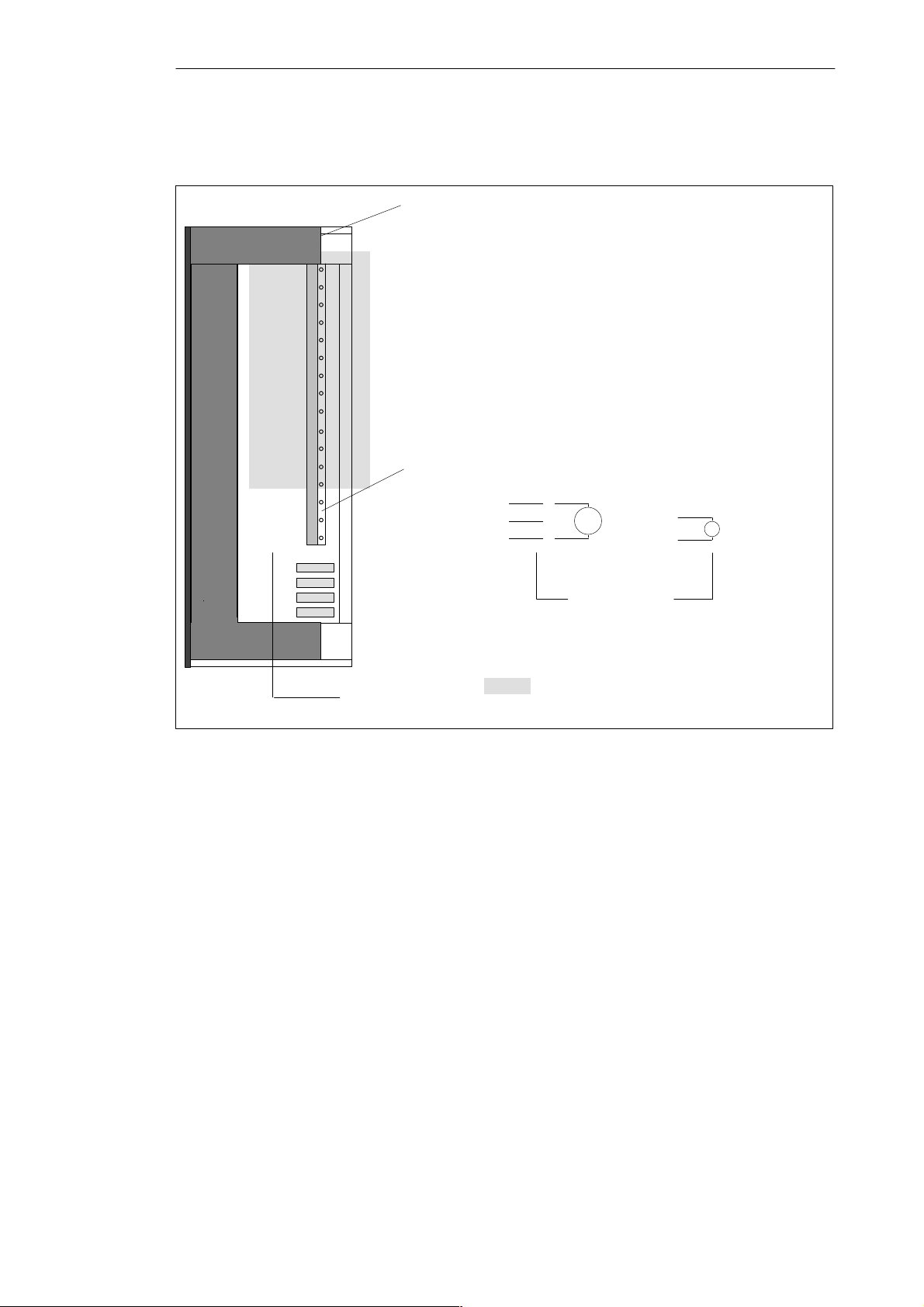
C7-621 Analog I/Os
T erminal Diagram
AO-U
AO-I
AO-M
Figure 7-10 shows the terminal diagram of the analog output module.
View from the right of the C7-621
Analog output
Voltage output
14
15
16
V
Current output
A
Pin name
Figure 7-10 Terminal Diagram of the Analog Outputs
Connection
These shaded sections are irrelevant for
this example.
7-16
C7-621 / C7-621 AS-i Control Systems
C79000-G7076-C621-01
Page 99
C7-621 Analog I/Os
Analog Output
The following table contains the technical data of the analog output of the
C7 CPU.
Module-Specific Data
Number of outputs 1
Cable length
S shielded max. 100 m
Analog Value Formation
Resolution (including
overflow)
Conversion time
Settling time
S For ohmic load
S For capacitive load
S For inductive load
Substitute values applied
Noise Suppression, Error Limits
Error limits (in the entire
temperature range related to
the output area)
S Voltage output
S Current output
Error limit (error limit at 25
°C, related to the output area
S Voltage output
S Current output
Temperature error (related to
output range)
Linearity error (related to
output range)
Reproducibility accuracy (in
settled state at 25 °C, related to
output range
Output ripple: Range 0 to 50
kHz (related to output range)
Status, Interrupts, Diagnostics
11 bits + sign
40 ms
0.6 ms
1.0 ms
0.5 ms
no
" 1.0 %
" 1.0 %
" 0.8 %
" 0.9 %
" 0.01 %/K
" 0.06 %
" 0.05 %
" 0.05 %
Data for Selecting an Actuator
Output ranges (rated values)
S Voltage
S Current
Load resistance
S For voltage output
Capacitive load
S For current output
Inductive load
Voltage output
S Short circuit protection
S Short circuit current
Current output
" 10 V
" 20 mA
min. 2.0 kW
max. 0.1 mF
max. 300 W
max. 0.1 mH
yes
max. 40 mA
S Idle voltage max. 16 V
Immunity limit against
externally applied
voltages/currents
S Voltages at output against
M
ANA
S Current
Connection of actuators
max. " 15 V
permanent;
" 15 V for max. 1 s
(pulse duty factor
1:20)
max. 30 mA
S For voltage output
2-wire connection
4-wire connection
Possible
Not possible
S For current output
2-wire connection
Possible
Interrupts none
Diagnostic functions none
C7-621 / C7-621 AS-i Control Systems
C79000-G7076-C621-01
7-17
Page 100

C7-621 Analog I/Os
7-18
C7-621 / C7-621 AS-i Control Systems
C79000-G7076-C621-01
 Loading...