

Page 1
SIMATIC Industrial PC SIMATIC Box PC 840 V2
DOCUMENTATION
Getting Started Edition 05/2006
Industrial PC
Box PC 840 V2
simatic
DOCUMENTATION
Page 2

Page 3

SIMATIC
Industrial PC
SIMATIC Box PC 840 V2
Getting Started
Introduction
Description
Application planning
Installation
Connecting
Commissioning
Troubleshooting
1
2
3
4
5
6
7
Dimensional drawings
Appendix
8
A
Edition 05/2006
A5E00244266-02
Page 4

Safety Guidelines
This manual contains notices you have to observe in order to ensure your personal safety, as well as to prevent
damage to property. The notices referring to your personal safety are highlighted in the manual by a safety alert
symbol, notices referring only to property damage have no safety alert symbol. These notices shown below are
graded according to the degree of danger.
Danger
indicates that death or severe personal injury will result if proper precautions are not taken.
Warning
indicates that death or severe personal injury may result if proper precautions are not taken.
Caution
with a safety alert symbol, indicates that minor personal injury can result if proper precautions are not taken.
Caution
without a safety alert symbol, indicates that property damage can result if proper precautions are not taken.
Notice
indicates that an unintended result or situation can occur if the corresponding information is not taken into
account.
If more than one degree of danger is present, the warning notice representing the highest degree of danger will
be used. A notice warning of injury to persons with a safety alert symbol may also include a warning relating to
property damage.
Qualified Personnel
The device/system may only be set up and used in conjunction with this documentation. Commissioning and
operation of a device/system may only be performed by qualified personnel. Within the context of the safety notes
in this documentation qualified persons are defined as persons who are authorized to commission, ground and
label devices, systems and circuits in accordance with established safety practices and standards.
Prescribed Usage
Note the following:
Warning
This device may only be used for the applications described in the catalog or the technical description and only in
connection with devices or components from other manufacturers which have been approved or recommended
by Siemens. Correct, reliable operation of the product requires proper transport, storage, positioning and
assembly as well as careful operation and maintenance.
Trademarks
All names identified by ® are registered trademarks of the Siemens AG. The remaining trademarks in this
publication may be trademarks whose use by third parties for their own purposes could violate the rights of the
owner.
Disclaimer of Liability
We have reviewed the contents of this publication to ensure consistency with the hardware and software
described. Since variance cannot be precluded entirely, we cannot guarantee full consistency. However, the
information in this publication is reviewed regularly and any necessary corrections are included in subsequent
editions.
Siemens AG
Automation and Drives
Postfach 48 48
90437 NÜRNBERG
GERMANY
Order No.: A5E00244266-02
Edition 05/2006
Copyright © Siemens AG
2004 - 2006.
Technical data subject to change
Page 5

Table of contents
1 Introduction............................................................................................................................................. 1-1
2 Description.............................................................................................................................................. 2-1
2.1 Design........................................................................................................................................ 2-1
2.1.1 External structure....................................................................................................................... 2-1
2.1.2 Operator Controls ...................................................................................................................... 2-3
2.1.3 Connection components ............................................................................................................ 2-4
3 Application planning................................................................................................................................ 3-1
3.1 Transport.................................................................................................................................... 3-1
3.2 Unpacking and checking the delivery unit ................................................................................. 3-1
3.3 Device identification data........................................................................................................... 3-2
3.4 Ambient and Environmental Conditions..................................................................................... 3-3
3.5 Permitted mounting positions..................................................................................................... 3-4
4 Installation .............................................................................................................................................. 4-1
4.1 Installing the device ................................................................................................................... 4-1
5 Connecting ............................................................................................................................................. 5-1
5.1 Connecting peripherals .............................................................................................................. 5-1
5.2 Connecting the 120 V / 230 V Ac power supply ........................................................................ 5-2
5.3 Connecting the (24 V) DC power supply ................................................................................... 5-5
5.4 Connecting the equipotential bonding circuit............................................................................. 5-6
6 Commissioning ....................................................................................................................................... 6-1
6.1 Requirements for commissioning............................................................................................... 6-1
6.2 Initial Commissioning - Initial Startup......................................................................................... 6-1
6.3 Reinstalling the software............................................................................................................ 6-2
6.3.1 General installation procedure................................................................................................... 6-2
7 Troubleshooting...................................................................................................................................... 7-1
7.1 General problems ...................................................................................................................... 7-1
8 Dimensional drawings............................................................................................................................. 8-1
8.1 Dimensional Drawing of the Device........................................................................................... 8-1
A Appendix.................................................................................................................................................A-1
A.1 Guidelines and Declarations ...................................................................................................... A-1
A.2 Certificates and Approvals.........................................................................................................A-2
A.3 Service and support ................................................................................................................... A-4
SIMATIC Box PC 840 V2
Getting Started, Edition 05/2006, A5E00244266-02
iii
Page 6

Table of contents
SIMATIC Box PC 840 V2
iv Getting Started, Edition 05/2006, A5E00244266-02
Page 7

Introduction
Purpose of this Document
This compact documentation contains all the information you need for commissioning and
using the SIMATIC Box PC 840 V2.
Scope of validity of this document
This documentation is valid for all supplied variations of the SIMATIC Box PC 840 V2 and
describes the state of delivery as of May 2006.
Operating instructions SIMATIC Box PC 840 V2
The operating instructions are available on the supplied "Documentation and Drivers" CD. To
view and print the operating instructions, run Start and follow the instructions on the screen.
The operating instructions provide useful information on many topics such as the hardware
expansion options, modification of the system configuration and technical data.
Conventions
The abbreviation Box PC or device is also used within this documentation for the product
name SIMATIC Box PC 840 V2.
1
SIMATIC Box PC 840 V2
Getting Started, Edition 05/2006, A5E00244266-02
1-1
Page 8

Introduction
SIMATIC Box PC 840 V2
1-2 Getting Started, Edition 05/2006, A5E00244266-02
Page 9
Description
2.1 2.1 Design
2.1.1 External structure
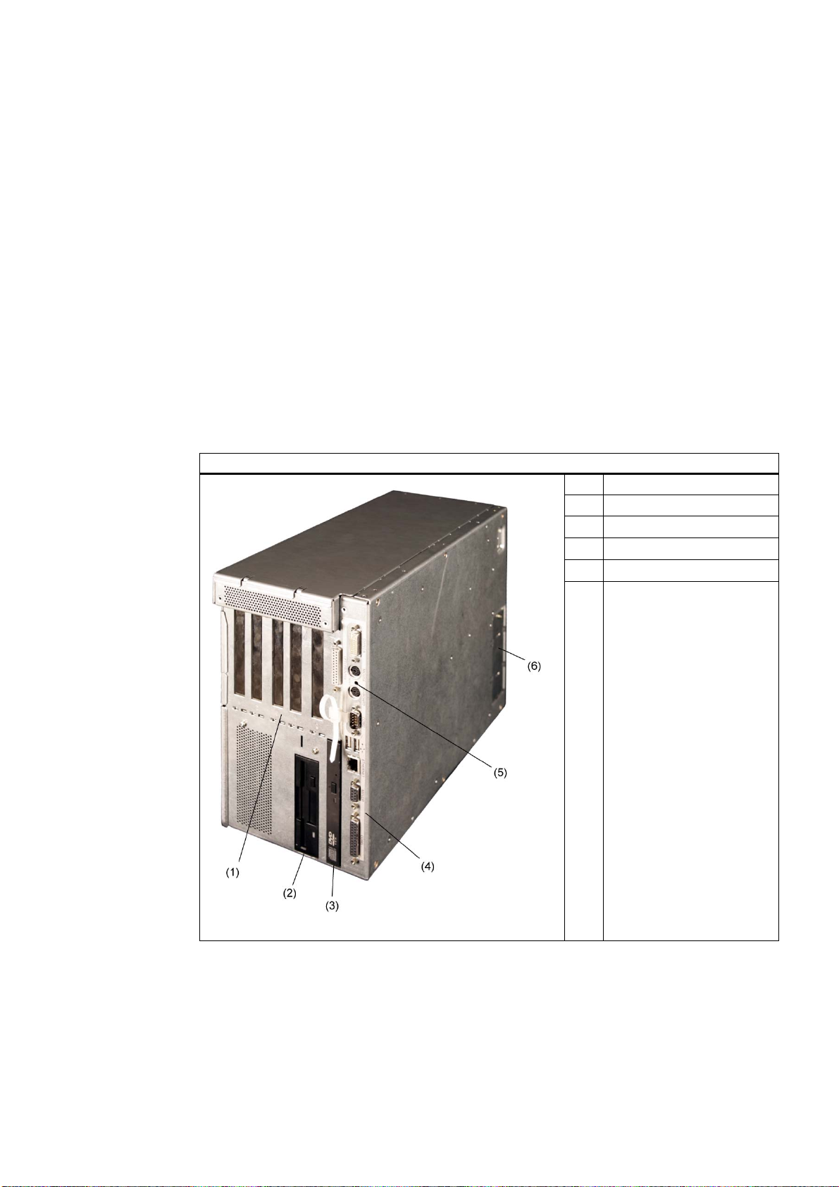
Front view
2
(1) Expansion slots
(2) Floppy disk
(3) DVD-/CD drive
(4) Front interfaces
(5) Reset button
(6) Steel cover plate for the
operator panel interfaces
SIMATIC Box PC 840 V2
Getting Started, Edition 05/2006, A5E00244266-02
2-1
Page 10
Description
2.1 Design
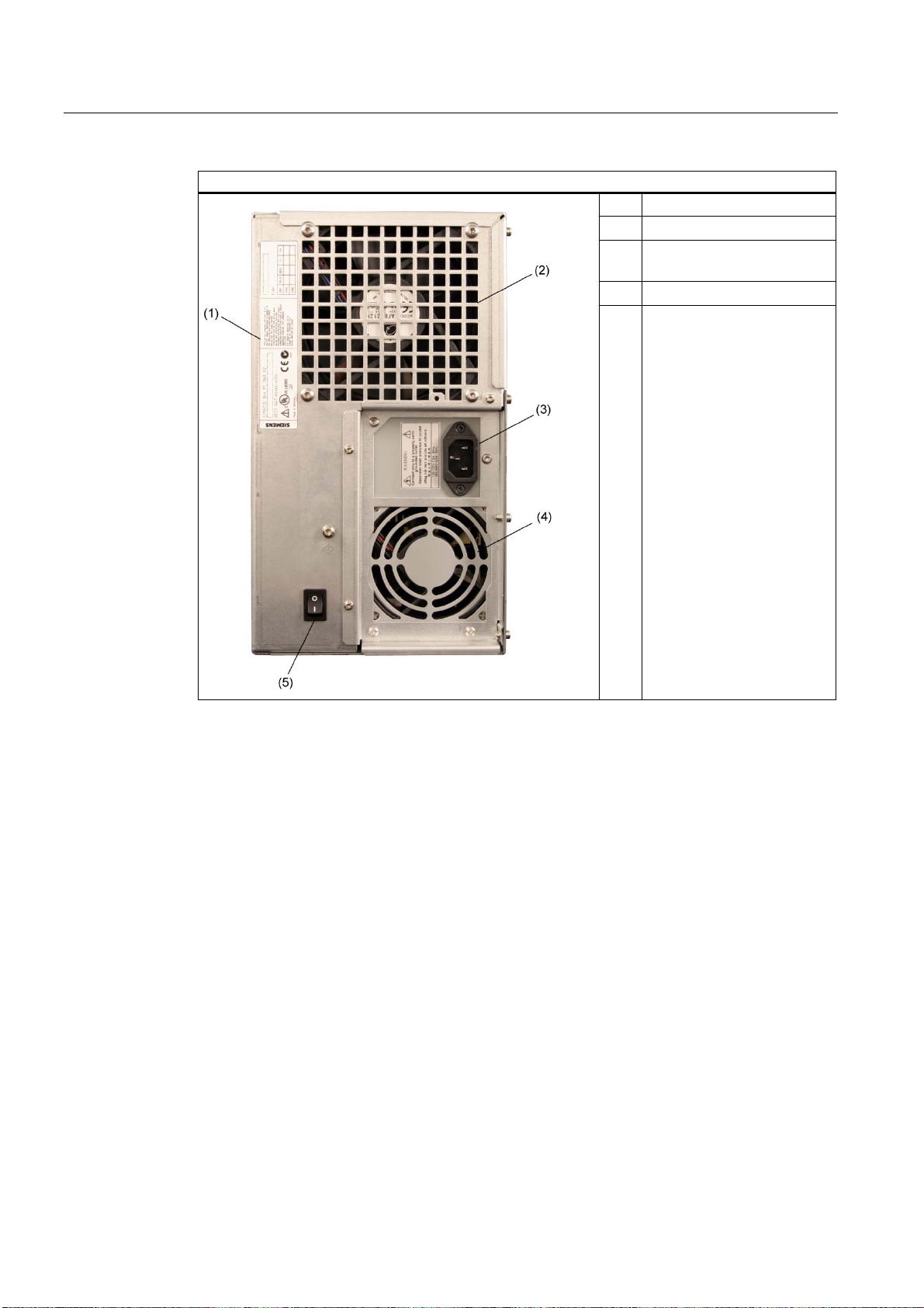
Rear view
(1) Rating plate
(2) Equipment fan
(3) IEC power connector (screw
terminals with 24 V DC)
(4) Power supply module fan
(5) On / Off switch
SIMATIC Box PC 840 V2
2-2 Getting Started, Edition 05/2006, A5E00244266-02
Page 11
Description
2.1 Design
2.1.2 Operator Controls
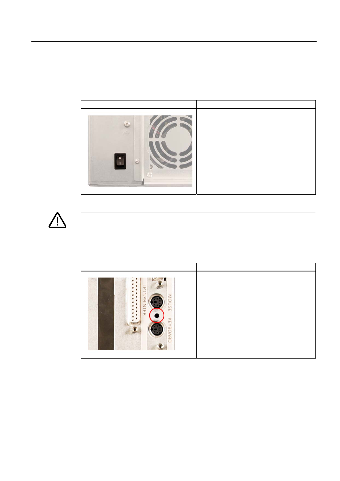
On / Off switch
On / Off switch Description
The On / Off switch does not disconnect the
device from mains. When the switch is in 0
position (Off), the device is still connected to the
auxiliary voltage.
Reset button
Warning
The On / Off switch does not disconnect the device from mains.
Reset button Description
The reset button can be actuated with a pin or an
opened up paper clip, for example. The button
signal triggers a hardware reset. The PC performs
a restart (cold start.)
Caution
Data may be lost when the PC performs a hardware reset!
SIMATIC Box PC 840 V2
Getting Started, Edition 05/2006, A5E00244266-02
2-3
Page 12
Description
2.1 Design
2.1.3 Connection components
Ports
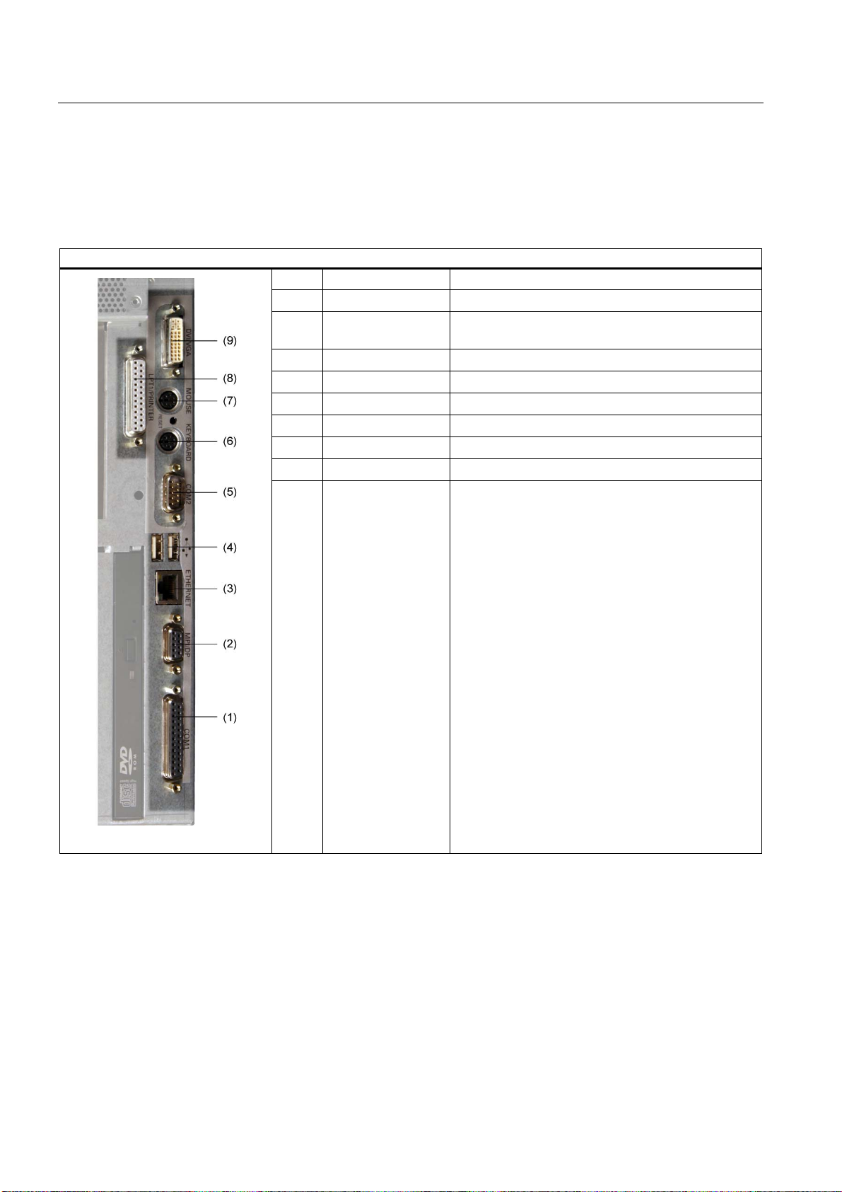
Arrangement of the ports on the front of the device
Pos Name Description
(1) COM 1 Serial port 1 (V.24), 25-pin D-sub socket
(2) PROFIBUS/MPI/DP MPI interface (RS485, electrically isolated), optional
9-pin D-sub socket
(3) ETHERNET RJ 45 Ethernet connection 10/100 Mbps
(4) USB 2.0 USB connector Right USB port 1, left USB port 2
(5) COM2 Serial port (V.24), 9-pin D-sub plug
(6) KEYBOARD Connection for a PS/2 keyboard
(7) Mouse Connection for a PS/2 mouse
(8) LPT1 Parallel interface, 25-pin
(9) DVI/VGA DVI/VGA connection for CRT or LCD monitor with
DVI interface, VGA via DVI/VGA adapter (included in
Box PC package)
SIMATIC Box PC 840 V2
2-4 Getting Started, Edition 05/2006, A5E00244266-02
Page 13
Description
2.1 Design
Interfaces for connecting operator panels / displays
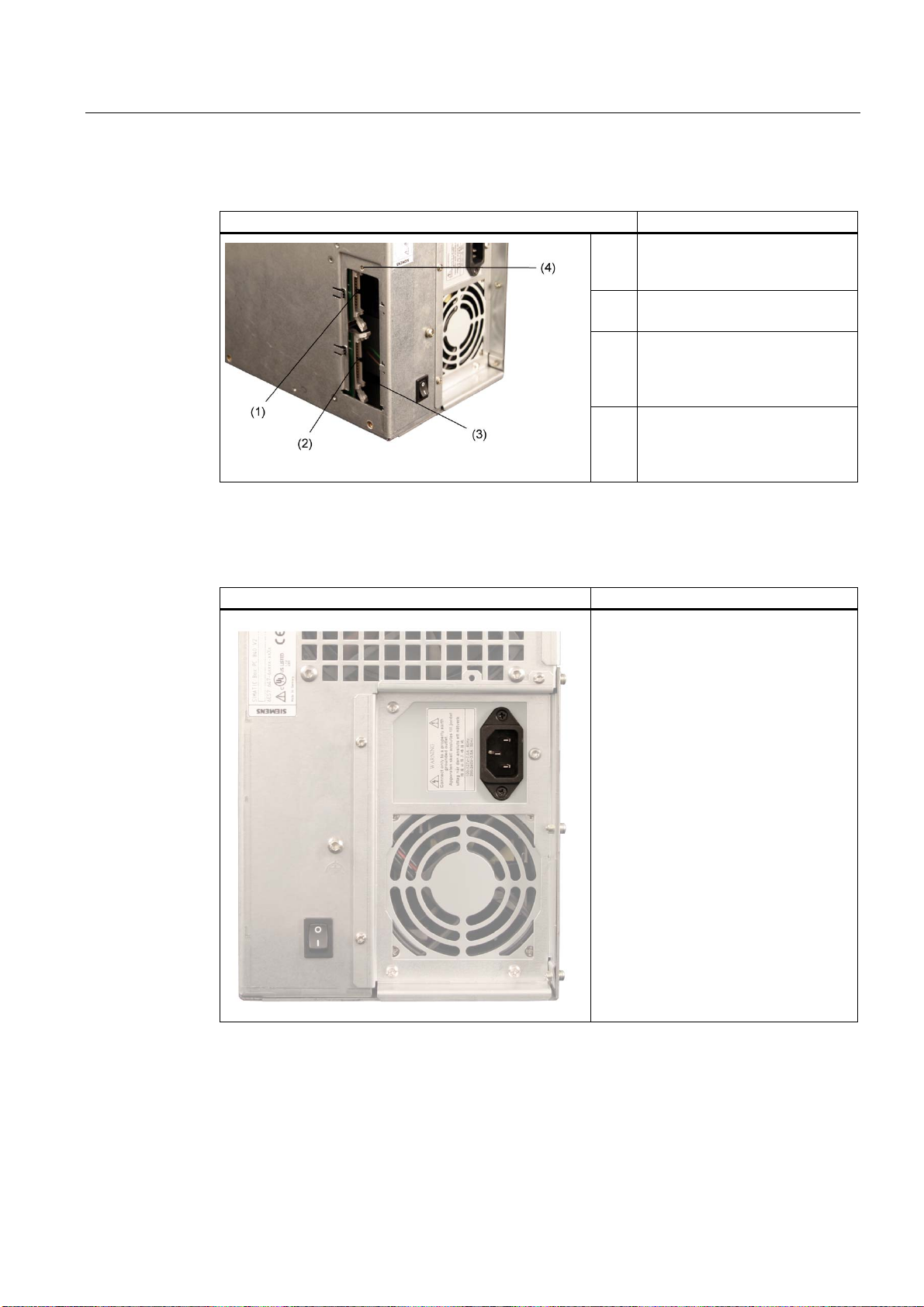
Arrangement of the interfaces
(1) LVDS display interface
for TFT displays up to
1024 x 768 pixels
(2) I/O interface for connecting front
panel components
(3) Access to the interfaces on
operator panels (closed by a
screwed metal cover during
shipment of Box PC)
(4) Mounting screw for the steel
sheet cover
AC power supply
Position of the IEC power connector Description
IEC power connector for the AC power
supply to the device. The maximum
permitted power range is 120 V AC to
240 V AC.
SIMATIC Box PC 840 V2
Getting Started, Edition 05/2006, A5E00244266-02
2-5
Page 14
Description
2.1 Design
DC power supply
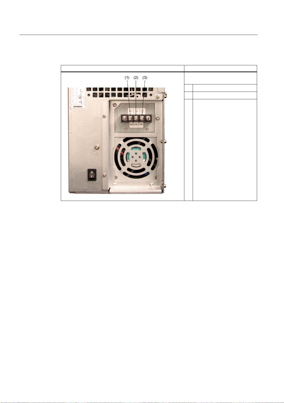
Position of the screw terminals Description
Screw terminals for connecting the
DC power supply to the device
1 24 VDC
2 0 VDC
3 Protective conductor
SIMATIC Box PC 840 V2
2-6 Getting Started, Edition 05/2006, A5E00244266-02
Page 15

Application planning
3.1 3.1 Transport
Despite the device's rugged design, its internal components are sensitive to severe
vibrations or shock. You must therefore protect the PC from severe mechanical stress when
transporting it.
You should always use the original packaging for shipping and transporting the device.
Caution
Risk of damage to the device!
When transporting the PC in cold weather, it may be submitted to extreme variations in
temperature. In this situation, ensure that no moisture (condensation) develops on or inside
the device.
If condensation has developed, wait at least 12 hours before you switch on the device.
3
Notice
When transporting the device, there is a risk that the drive drawer may open and be
damaged or that the drive may be soiled. A piece of Scotch tape serves as transport
safeguard and this should be used for every transportation.
3.2 3.2 Unpacking and checking the delivery unit
Unpacking the device
Note the following points when you unpack the unit
• It is advisable not to dispose of the original packing material. Keep it in case you have to
transport the unit again.
• Please keep the documentation in a safe place. It is required for initial commissioning and
is part of the device.
• Check the delivery unit for any visible transport damage.
• Verify that the shipment contains the complete unit and your separately ordered
accessories. Please inform your local dealer of any disagreements or transport damages.
SIMATIC Box PC 840 V2
Getting Started, Edition 05/2006, A5E00244266-02
3-1
Page 16
Application planning
3.3 Device identification data
3.3 3.3 Device identification data
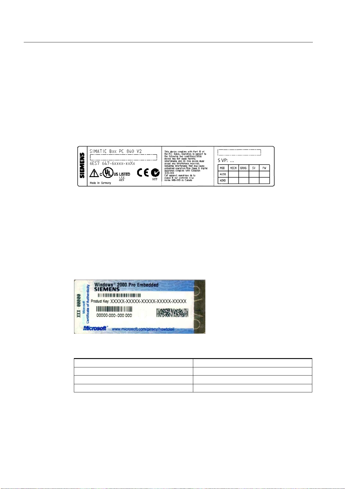
The device can identified uniquely with the help of these numbers in case of repairs or theft.
Enter the following data in the table below:
• Serial number: The serial number is found on the rating plate.
Rating plate
Figure 3-1 Rating plate
COA label
• Order number of the device
• Ethernet address: The Ethernet address of the device can be viewed in the BIOS Setup
(F2) under Main > Hardware Options > Ethernet Address.
• Microsoft Windows "Product Key" from the "Certificate of Authenticity" (COA). The COA
label is bonded to the device. The Product Key is always required to reinstall the
operating system.
Figure 3-2 COA label
Serial number S VP ...
Order No. 6ES ...
Microsoft Windows Product Key
Ethernet address
SIMATIC Box PC 840 V2
3-2 Getting Started, Edition 05/2006, A5E00244266-02
Page 17

Application planning
3.4 Ambient and Environmental Conditions
3.4 3.4 Ambient and Environmental Conditions
Please note the following when you plan your project:
• The climatic and mechanical environmental conditions specified in the specifications
provided by your operating instructions.
• The clearance in the area of the ventilation slots must be at least 100 mm, so that the PC
is sufficiently ventilated.
• Do not cover the vent slots of the device.
• The device with AC power supply satisfies fire protection requirements to EN 60950-1. It
may therefore be installed without additional fire-proofing measures.
• The device with DC power supply does not satisfy fire protection requirements to
EN 60950-1. It must therefore be installed in order to comply with the requirements for a
fire-resistant enclosure.
• Always observe the mounting positions permitted for this device.
Warning
Failure to adhere to these conditions when mounting the system voids the approvals
based on UL 60950-1, UL 508 and EN 60950-1!
SIMATIC Box PC 840 V2
Getting Started, Edition 05/2006, A5E00244266-02
3-3
Page 18
Application planning
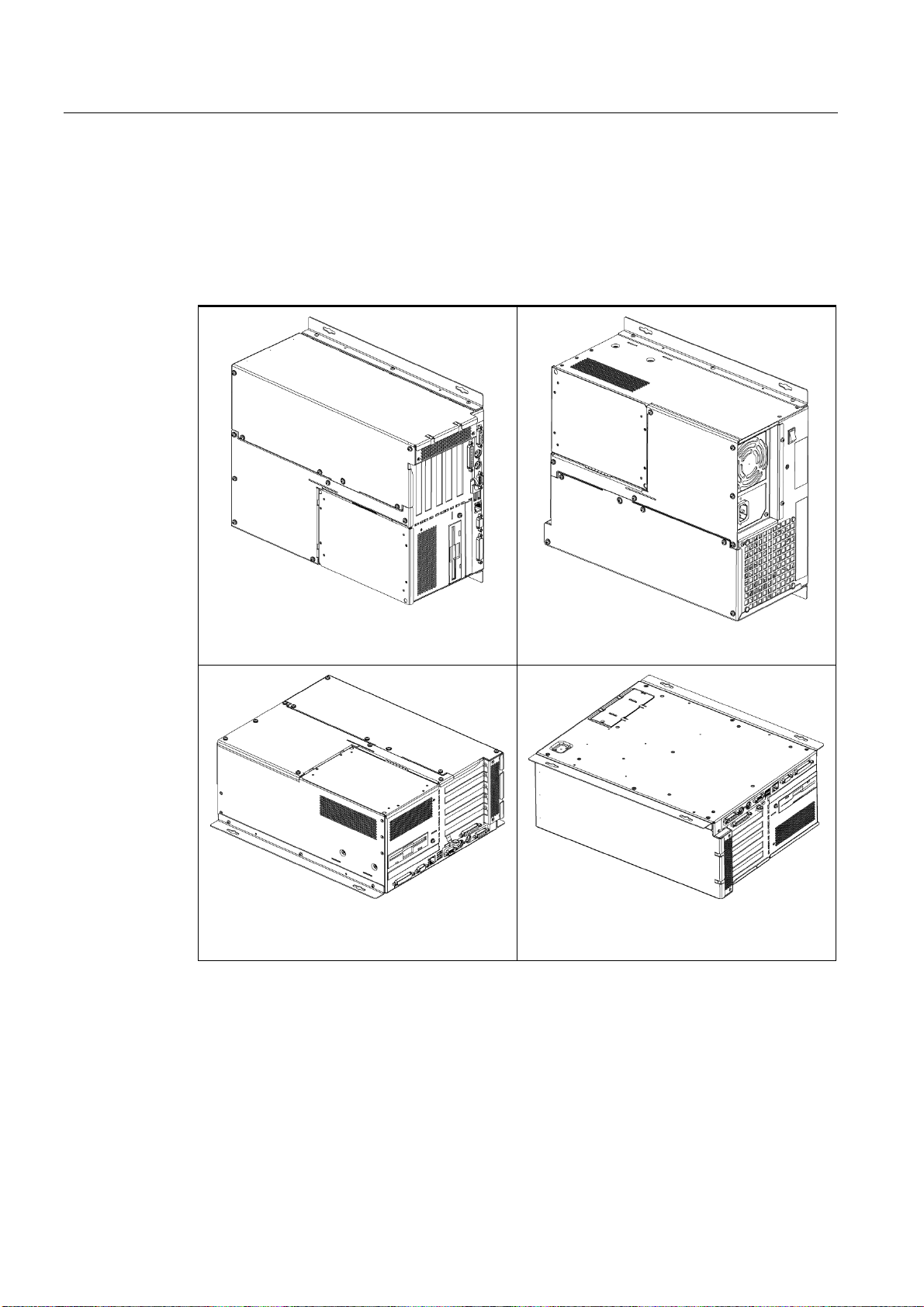
3.5 Permitted mounting positions
3.5 3.5 Permitted mounting positions
PC mounting positions according to UL60950-1/UL508/EN60950-1/CSA22.2 No. 60950-1
An inclination of ± 20° is permitted for all approved mounting positions.
Position 1 (preferred)
Position 3 (desktop)
Position 2
Position 4 (ceiling)
CD/DVD and floppy drives may not be operated.
SIMATIC Box PC 840 V2
3-4 Getting Started, Edition 05/2006, A5E00244266-02
Page 19
Application planning
3.5 Permitted mounting positions
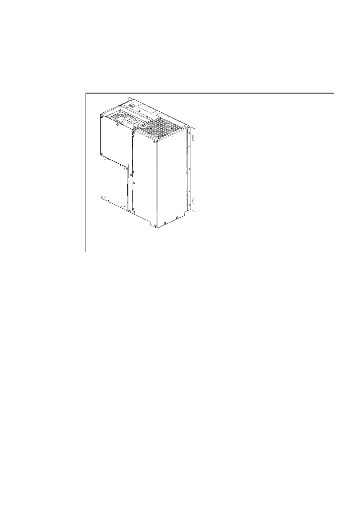
Additional permissible PC mounting positions according to UL508/CSA 22.2 No. 142
An inclination of ±15° is allowed in this mounting position.
Position 5 (ports facing down)
CD/DVD and floppy drives may not be operated.
SIMATIC Box PC 840 V2
Getting Started, Edition 05/2006, A5E00244266-02
3-5
Page 20

Application planning
3.5 Permitted mounting positions
SIMATIC Box PC 840 V2
3-6 Getting Started, Edition 05/2006, A5E00244266-02
Page 21
Installation
4.1 4.1 Installing the device
The SIMATIC Box PC 840 V2 is particularly suitable for installation in control desks, switch
cabinets and switchboards
Warning
Function test while installing the device in machines or execute systems
Following the results of a risk analysis, additional protection equipment on the machine or
the system is necessary to avoid endangering persons. With this, especially the
programming, configuration and wiring of the inserted I/O modules have to be executed, in
accordance with the necessary risk analysis identified safety performance (SIL, PL or Cat.).
The intended use of the device has to be secured.
The proper use of the device has to be varified with a function test on the system. This test
can detect programming, configuration and wiring errors. The test results have to be
documented and if necessary inserted into the relevant inputs.
4
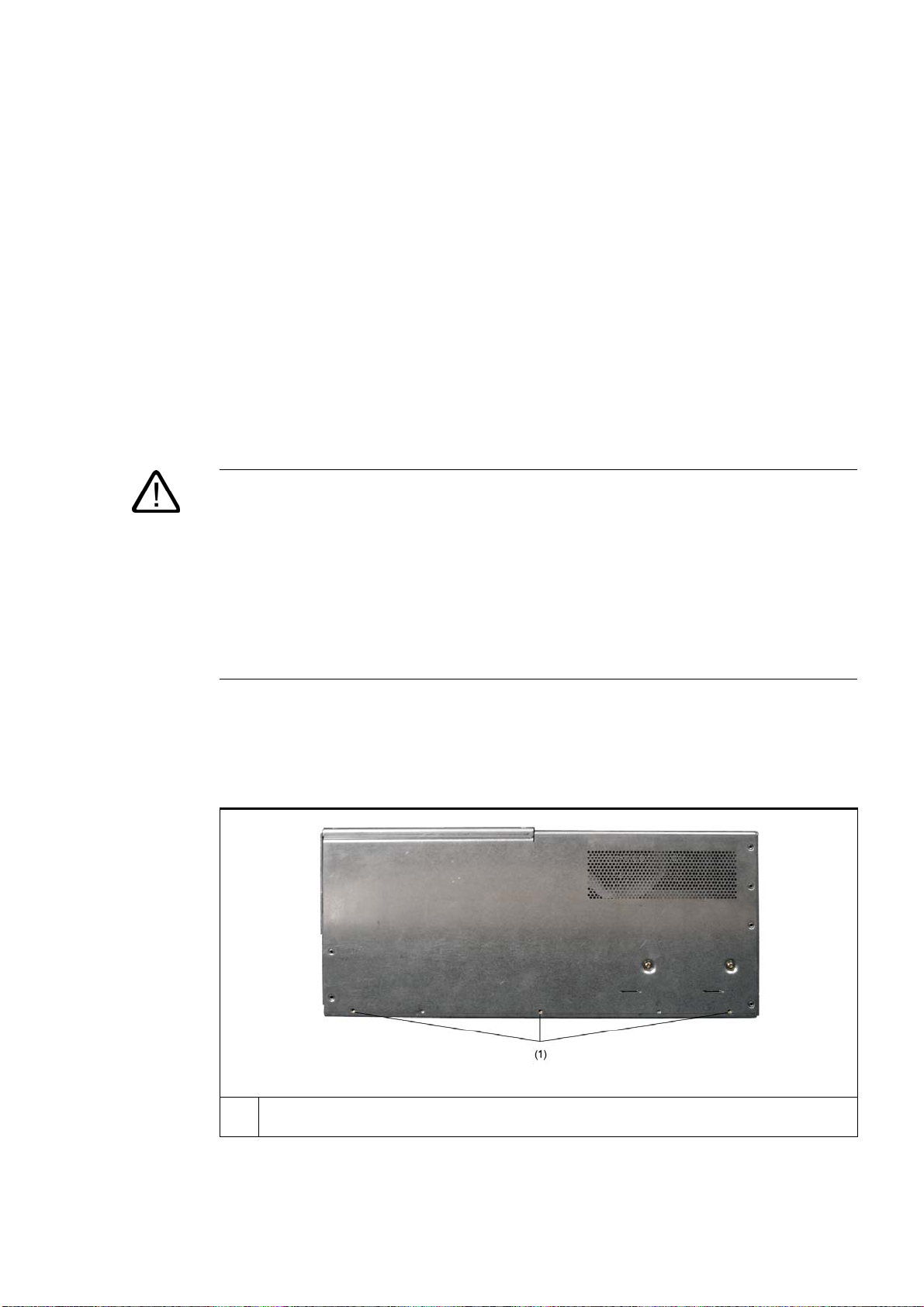
Screw-mounting the brackets
Two brackets are included, depending on the device version. You can attach these to the PC
housing using six M3 x 6 mm screws.
(1) Mount the brackets onto the device using the included M3 x 5 mm screws with a max. insertion
depth of 5 mm (included in package).
SIMATIC Box PC 840 V2
Getting Started, Edition 05/2006, A5E00244266-02
4-1
Page 22
Installation
4.1 Installing the device
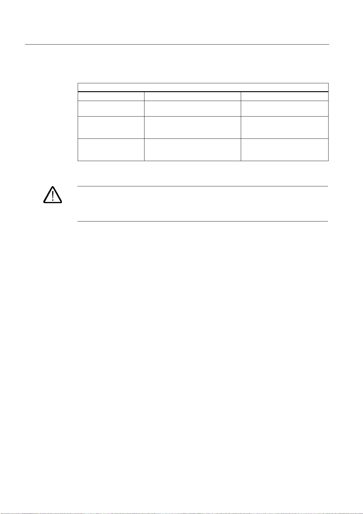
Instructions for ceiling or wall mounting
Mounting examples
Stock Bore diameter Fixation
Concrete 8 mm diameter, 60 mm depth Dowel: 8 mm, 50 mm
screws 4 mm, 50 mm
Plasterboard
(min. 13 mm thick)
Metal
(min. 2 mm thick)
14 mm diameter Tilting dowel
diameter 4 mm
min. length 50 mm
5 mm diameter Metal screws
diameter 4 mm
min. length 15 mm
Warning
Ensure that the wall or ceiling is capable of carrying four times the total weight of your
Box PC 840 V2 (including brackets and expansion modules.) The total weight is
approx. 10 kg.
SIMATIC Box PC 840 V2
4-2 Getting Started, Edition 05/2006, A5E00244266-02
Page 23

Connecting
5.1 5.1 Connecting peripherals
Note before connecting
Notice
Connect only I/O modules approved for industrial applications to EN 61000-6-2:2001.
Note
Hot-plug I/O modules (USB) may be connected while the PC is in operation.
5
Caution
I/O devices not capable of hot-plugging may only be connected after the device has been
disconnected from the power supply.
Caution
Strictly adhere to the specifications for I/O modules.
SIMATIC Box PC 840 V2
Getting Started, Edition 05/2006, A5E00244266-02
5-1
Page 24

Connecting
5.2 Connecting the 120 V / 230 V Ac power supply
5.2 5.2 Connecting the 120 V / 230 V Ac power supply
To be noted before you connect the device
Note
The varying voltage power supply module is designed for operation on 120/230/240 V AC
networks. The setting of the voltage range takes place automatically.
Caution
Do not connect or disconnect power and data cables during thunderstorms.
Caution
The device is designed for operation on grounded power supply networks (TN systems to
VDE 0100, Part 300, or IEC 60364-3).
It is not designed for operation on ungrounded or impedance-grounded power networks
(IT networks).
Caution
The permitted nominal voltage of the device must conform with local mains voltage.
Caution
The mains connector must be disconnected to fully isolate the device from mains. Ensure
easy access to this area.
A master mains disconnect switch must be installed if the device is mounted in a switch
cabinet.
Always ensure free and easy access to the power inlet on the device or that the safety
power outlet of the building installation is freely accessible and located close to the device.
SIMATIC Box PC 840 V2
5-2 Getting Started, Edition 05/2006, A5E00244266-02
Note
The power supply contains an active PFC (Power Factor Correction) circuit to conform to the
EMC guidelines.
Uninterruptible AC power systems (UPS) must supply a sinusoidal output voltage in the
normal and buffered mode when used with SIMATIC PCs with an active PFC.
UPS characteristics are described and classified in the standards EN 50091-3 and IEC
62040-3. Devices with sinusoidal output voltage in the normal and buffered mode are
identified with the classification “VFI-SS-....” or “VI-SS-....”.
Page 25
Connecting
5.2 Connecting the 120 V / 230 V Ac power supply
Localized information
Outside of the USA and Canada, operation on a 230 V power supply:
This device is equipped with a safety-tested power cord which may only be connected to a
grounded sealed contact power outlet. If you choose not to use this cable, you must use a
flexible cable of the following type: Min 18 AWG conductor cross-section and 15-A / 250-V
shockproof connector. The cable set must be compliant with the safety regulations and
stipulated IDs of the country where the system is to be installed.
For the USA and Canada:
For the United States and Canada, a CSA or UL-listed power cord must be used.
The connector must be compliant with NEMA 5-15.
120 V AC power supply
To be used is a flexible power cord approved to UL and with CSA label, and which has the
following features: Type SJT with three leads, min. 18 AWG conductor cross-section,
max. 4.5 m in length and parallel ground contact connector 15 A, min. 125 V.
240 V supply voltage
Use a flexible power cord with UL approval and with CSA label, and with the following
features: Type SJT with three leads, min. 18 AWG conductor cross-section, max. 4.5 m long
and tandem ground contact connector 15 A, min. 250 V.
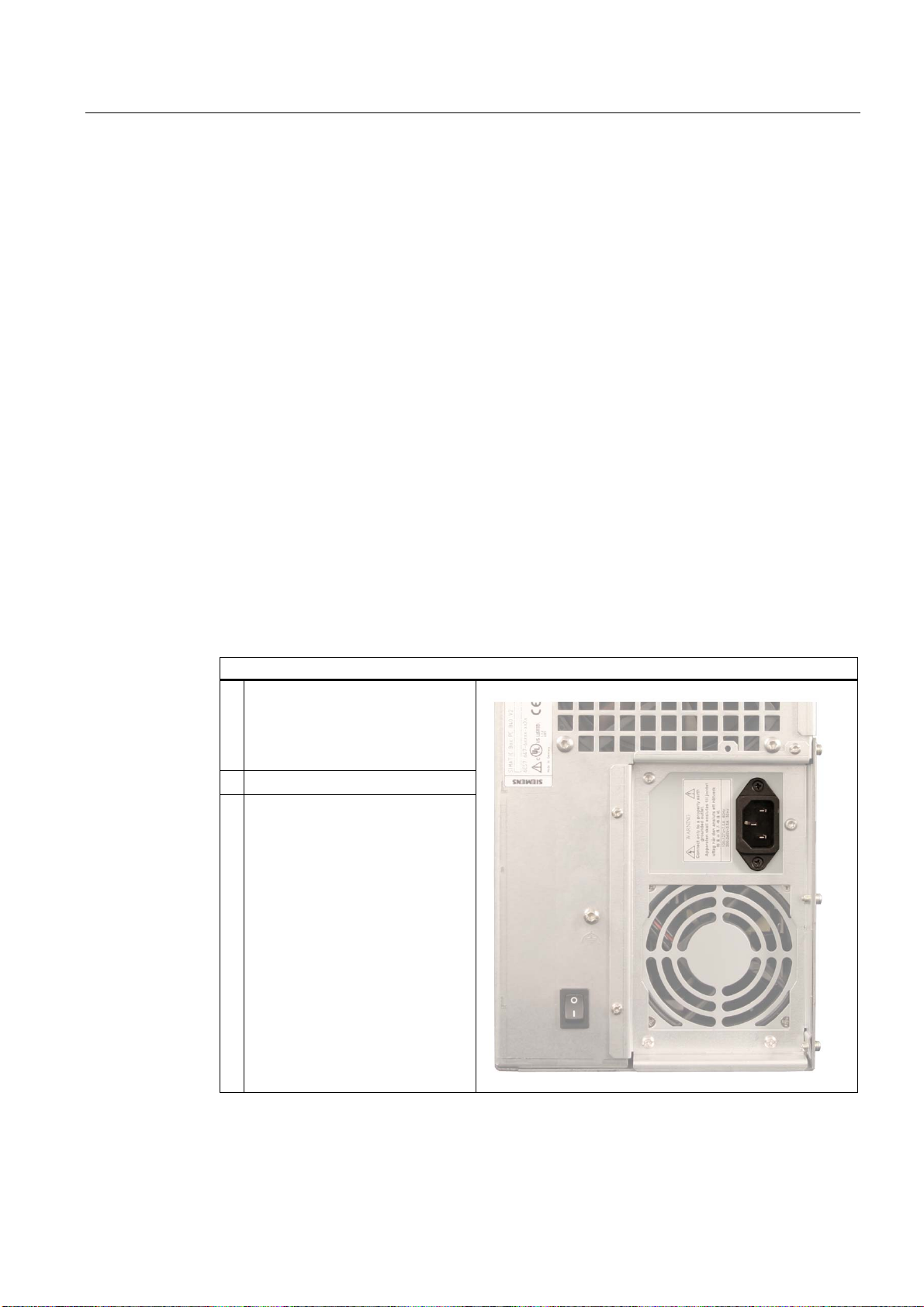
Connecting
How to connect the device to the 120 V AC / 230 V AC power supply
1. Make sure that the ON / OFF
switch is in "0" position (Off) when
you plug in the power cord in order
to avoid unintentional startup of the
device.
2. Connect the IEC connector
3. Connecting the power cord to the
power socket
SIMATIC Box PC 840 V2
Getting Started, Edition 05/2006, A5E00244266-02
5-3
Page 26
Connecting
5.2 Connecting the 120 V / 230 V Ac power supply
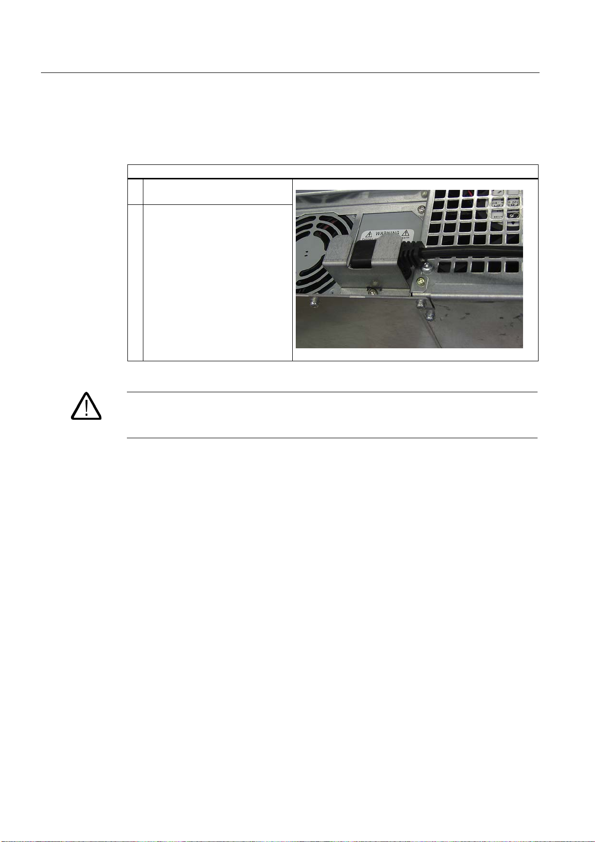
Secure the power plug
The supplied power plug locking mechanism prevents the power plug from being pulled out
accidentally.
Steps for securing the AC power cable
1. Remove the power supply retaining
screw
2. Screw the power plug locking
mechanism into position
Warning
If the power plug is secured with a clamp, the power outlet must be freely accessible to allow
the device to be easily removed from the mains.
SIMATIC Box PC 840 V2
5-4 Getting Started, Edition 05/2006, A5E00244266-02
Page 27
Connecting
5.3 Connecting the (24 V) DC power supply
5.3 5.3 Connecting the (24 V) DC power supply
Note before connecting
Warning
Only connect the device to 24 V DC power supply systems which meet the requirements of a
safe extra-low voltage (SELV); in addition, a protective conductor must be connected. The
conductors must withstand the short-circuit current of the 24 V DC power source, so that a
short-circuit will not damage the cable. You may connect cables with a cross section of
2
5 mm
.
Connecting
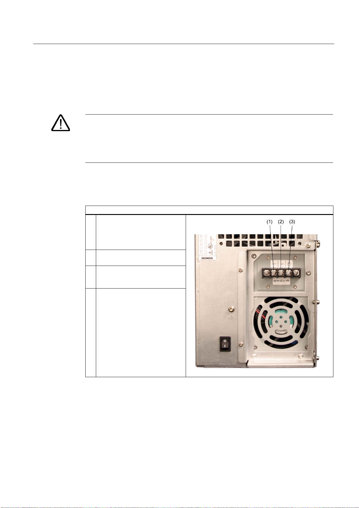
Steps for connecting the device to the 24 V DC power supply
1. Ensure that the ON/OFF switch is
in the '0' (OFF) position to prevent
unintentional startup of the device
when connecting it to the 24 V
power supply.
2. Switch off the 24 V DC power
source.
3. Connect the protective conductor
(3) to an appropriate screw
terminal
4. Connect +24 V DC (1) and 0 V DC
(2) to the screw terminals
SIMATIC Box PC 840 V2
Getting Started, Edition 05/2006, A5E00244266-02
5-5
Page 28
Connecting
5.4 Connecting the equipotential bonding circuit
5.4 5.4 Connecting the equipotential bonding circuit
A low-impedance earth connection ensures that interference signals generated by external
power supply cables, signal cables or cables to the I/O modules are safely discharged to
earth.
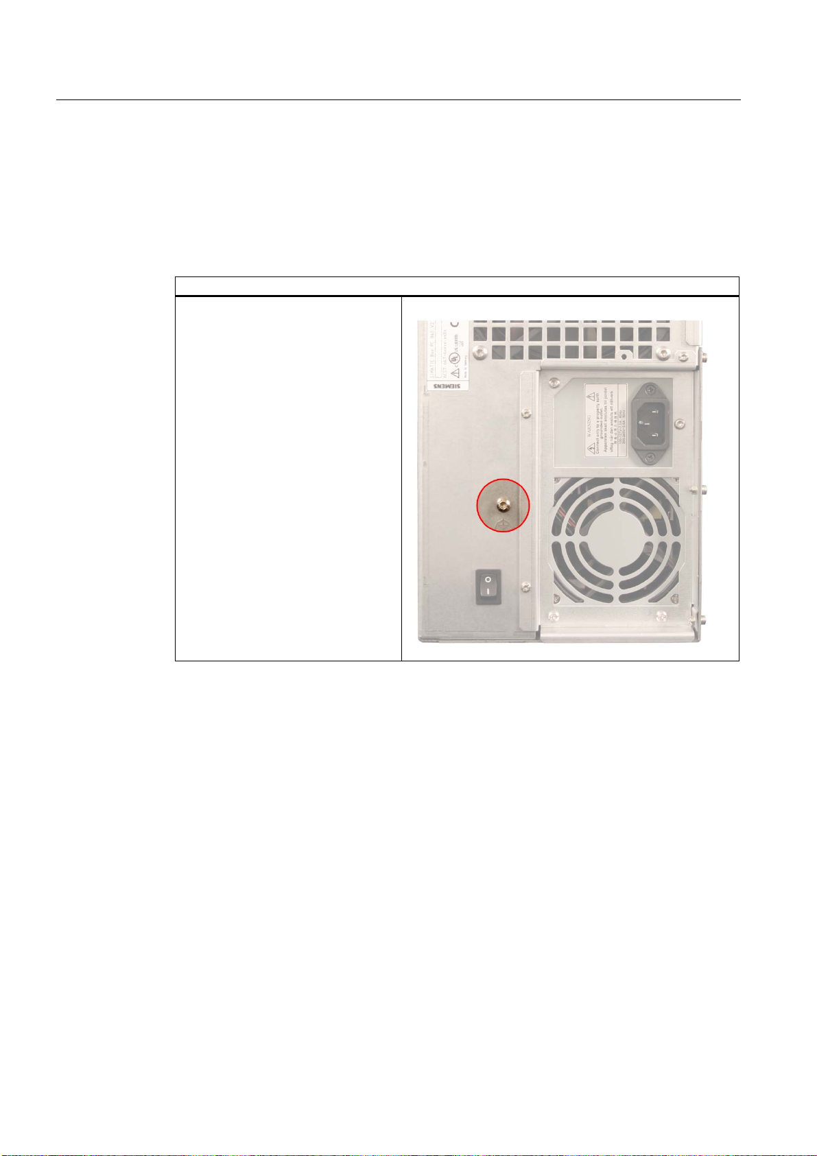
Equipotential bonding terminal
The equipotential bonding terminal on
the device (large surface, large-area
contact) must be connected with the
central grounding busbar of the cabinet
or plant in which the PC is to be
installed. The minimum conductor
cross-section may not be less than
2
5 mm
.
SIMATIC Box PC 840 V2
5-6 Getting Started, Edition 05/2006, A5E00244266-02
Page 29

Commissioning
6.1 6.1 Requirements for commissioning
• Before you switch on the device, you should verify that the peripherals are connected, i.e.
the keyboard, mouse, monitor and the power supply.
• The operating system of your device is preinstalled on the hard disk.
6.2 6.2 Initial Commissioning - Initial Startup
Caution
Risk of damage to the device!
Make sufficient allowances for the device to acquire room temperature before you put it
into use. If condensation develops, wait at least 12 hours before switching on the device.
The PC operating system is automatically set up the first time you switch on the device.
Procedure:
6
1. Set the ON / Off switch to I position (On). The PC performs a POST. During the self-test,
this message appears:
Press <F2> to enter SETUP or <ESC> to display the boot menu
2. Wait until this message is cleared, then follow the instructions on the screen.
3. Type in the Product Key as required. You can find this key on the "Certificate of
Authentication", in the "Product Key" line.
SIMATIC Box PC 840 V2
Getting Started, Edition 05/2006, A5E00244266-02
Notice
The PC may not be switched off when you run setup.
Do not change the default BIOS settings, otherwise the operating system setup may become
corrupted.
4. Automatic restart
6-1
Page 30

Commissioning
6.3 Reinstalling the software
After you have entered all necessary information and after the operating system
setup is completed, the PC is automatically restarted and displays the user interface of the
relevant operating system.
From now on, after you switch on the PC, the user interface of the operating system is
automatically opened when the startup routine is completed.
Switching off the device
Note
On a Windows platform, always shut down the PC by clicking Start > Close.
Set the ON / Off switch to 0 position (off.) Disconnect the mains connector to isolate the
device from mains.
6.3 6.3 Reinstalling the software
6.3.1 General installation procedure
In case of software errors, you can reinstall your software using the Recovery CD, the
Documentation and Drivers CD or the Restore DVD.
Recovery CD:
Contains the tools for setting up hard disk drives and the operating system.
Documentation and Drivers CD:
Contains the documentation and the hardware drivers.
Restore DVD:
Contains a hard disk image file with the original software (operating system with installed
hardware drivers).
SIMATIC Box PC 840 V2
6-2 Getting Started, Edition 05/2006, A5E00244266-02
Page 31

Troubleshooting
7.1 7.1 General problems
This chapter provides you with tips on how to localize and troubleshoot frequently occurring
problems.
Problem Possible causes To correct or avoid error
The device is not
operational
The external monitor
remains dark.
The mouse pointer
does not appear on
the screen.
Wrong time and/or
date on the PC.
Although the BIOS
setting is OK, the time
and data are still
wrong.
There is no power supply
to the device.
Device is being operated
outside the specified
ambient. conditions
The monitor is switched
off.
The monitor is in "power
save" mode.
The brightness button has
been set to dark.
The power cord or the
monitor cable is not
connected.
The mouse driver is not
loaded.
The mouse is not
connected.
The backup battery is
dead.
• Check the power supply, the network cable and the power plug.
• Check if the On/Off switch is in the correct position.
• Check the ambient conditions.
• After transport in cold weather, wait approximately 12 hours
before switching on the device.
Switch on the monitor.
Press any key on the keyboard.
Increase the screen brightness. For detailed information, refer to the
monitor operating instructions.
• Check whether the power cord has been properly connected to
the monitor and to the system unit or to the grounded shockproof
outlet.
• Check whether the monitor cable has been properly connected to
the system unit and to the monitor.
If the monitor screen still remains dark after you have performed
these checks, please contact your technical support team.
1. Check whether the mouse driver is properly installed and present
when you start the application program.
Check whether the mouse lead is connected to the system unit. If you
are using an adapter or extension for the mouse lead, check the
connectors.
Should the mouse cursor still not be visible on-screen after
completing these checks and measures, contact technical support.
1. Press <F2> within the boot sequence to open the BIOS Setup.
2. Set the time and date in the setup menu.
In this case, please contact your technical support team.
7
SIMATIC Box PC 840 V2
Getting Started, Edition 05/2006, A5E00244266-02
7-1
Page 32

7 Troubleshooting
7.1 7.1 General problems
Problem Possible causes To correct or avoid error
USB device not
responding.
DVD: The front loader
does not open.
The USB ports are
disabled in your BIOS.
USB 2.0 device
connected but USB 2.0 is
disabled.
Operating system does
not support the USB port.
The device is switched off
or the open/close button
is disabled by a software
application.
Use a different USB port or enable the port.
Enable USB 2.0.
Enable USB Legacy Support for the mouse and keyboard.
For all other devices you need USB drivers for the specific operating
system.
Emergency removal of the data medium:
1. Switching off the device
2. Insert a pointed object, a pin for example, or an opened paper clip
into the emergency extraction opening of the drive. Apply slight
pressure to the contact until the front loader opens.
3. Pull the loader further out.
SIMATIC Box PC 840 V2
7-2 Getting Started, Edition 05/2006, A5E00244266-02
Page 33
Dimensional drawings
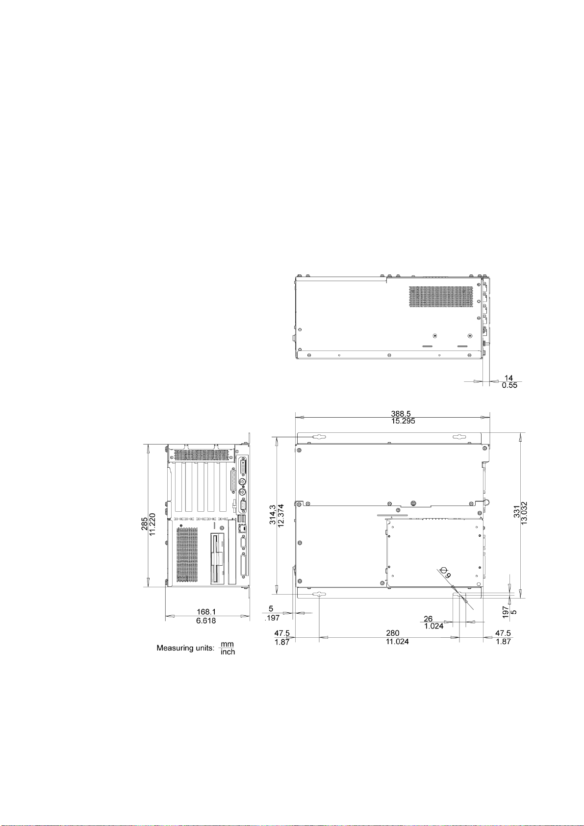
8.1 8.1 Dimensional Drawing of the Device
8
Figure 8-1 Dimensional drawing for mounting with angle bracket
SIMATIC Box PC 840 V2
Getting Started, Edition 05/2006, A5E00244266-02
8-1
Page 34
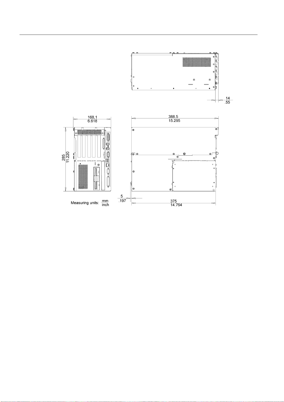
Dimensional drawings
8.1 Dimensional Drawing of the Device
Figure 8-2 Dimensional drawing for mounting without angle bracket
SIMATIC Box PC 840 V2
8-2 Getting Started, Edition 05/2006, A5E00244266-02
Page 35

A Appendix
A.1 A.1 Guidelines and Declarations
Notes on the CE markings
The following applies to the SIMATIC product described in this documentation:
EMC Guideline
AC voltage supply
The devices with AC power supply fulfill the requirements for the EC directive ™89/336/EEC
Electromagnetic Compatibility™ and the following fields of application apply according to this
CE label:
Area of Application Requirement for
Emitted interference Noise Immunity
Domestic housing area, business
and trade areas and small
businesses.
Industry EN 61000-6-4: 2001 EN 61000-6-2: 2001
A
EN 61000-6-3: 2001 EN 61000-6-1: 2001
The device is also compliant with EN 61000-3-2:2000 (harmonic currents) and
EN 61000-3-3:1995 (voltage fluctuation and flicker.)
DC power supply
The devices with DC power supply fulfill the requirements of the EC directive "89/336/EEC
Electromagnetic Compatibility", and the following fields of application apply according to this
CE label:
Area of Application Requirement for
Emitted interference Noise Immunity
Industry EN 61000-6-4: 2001 EN 61000-6-2: 2001
The device is also compliant with EN 61000-3-2:2000 (harmonic currents) and
EN 61000-3-3:1995 (voltage fluctuation and flicker.)
SIMATIC Box PC 840 V2
Getting Started, Edition 05/2006, A5E00244266-02
A-1
Page 36

Appendix A.2 Certificates and Approvals
Caution
This is Class A equipment. The equipment may cause radio interference in residential areas;
in such cases, the operator can be requested to take reasonable countermeasures.
Low-voltage directive
The devices with AC and DC power supply are compliant with the requirements of the EC
Directive 73/23/EEC "Low-Voltage Directive." Conformance with this directive has been
verified according to EN 60950-1.
Declaration of conformity
The EC declaration of conformity and the corresponding documentation are made available
to authorities in accordance with the EC directives stated above. Your sales representative
can provide these on request.
Note the installation guidelines
The installation guidelines and safety instructions in this documentation must be followed
during commissioning and operation.
Connecting peripherals
The requirements relating to noise immunity according to EN 61000-6-2:2001 are met when
you connect a peripheral suitable for an industrial environment. Peripheral devices are only
be connected via shielded cables.
A.2 A.2 Certificates and Approvals
DIN ISO 9001 certificate
The quality assurance system for the entire product process (development, production, and
marketing) at Siemens fulfills the requirements of ISO 9001 (corresponds to EN29001:
1987).
This has been certified by DQS (the German society for the certification of quality
management systems).
EQ-Net certificate no.: 1323-01
Software License Agreement
The device can be supplied with or without preinstalled software. For devices with
preinstalled software, please note the relevant license agreements.
SIMATIC Box PC 840 V2
A-2 Getting Started, Edition 05/2006, A5E00244266-02
Page 37
Appendix
A.2 Certificates and Approvals
Approvals for the USA, Canada and Australia
Product safety
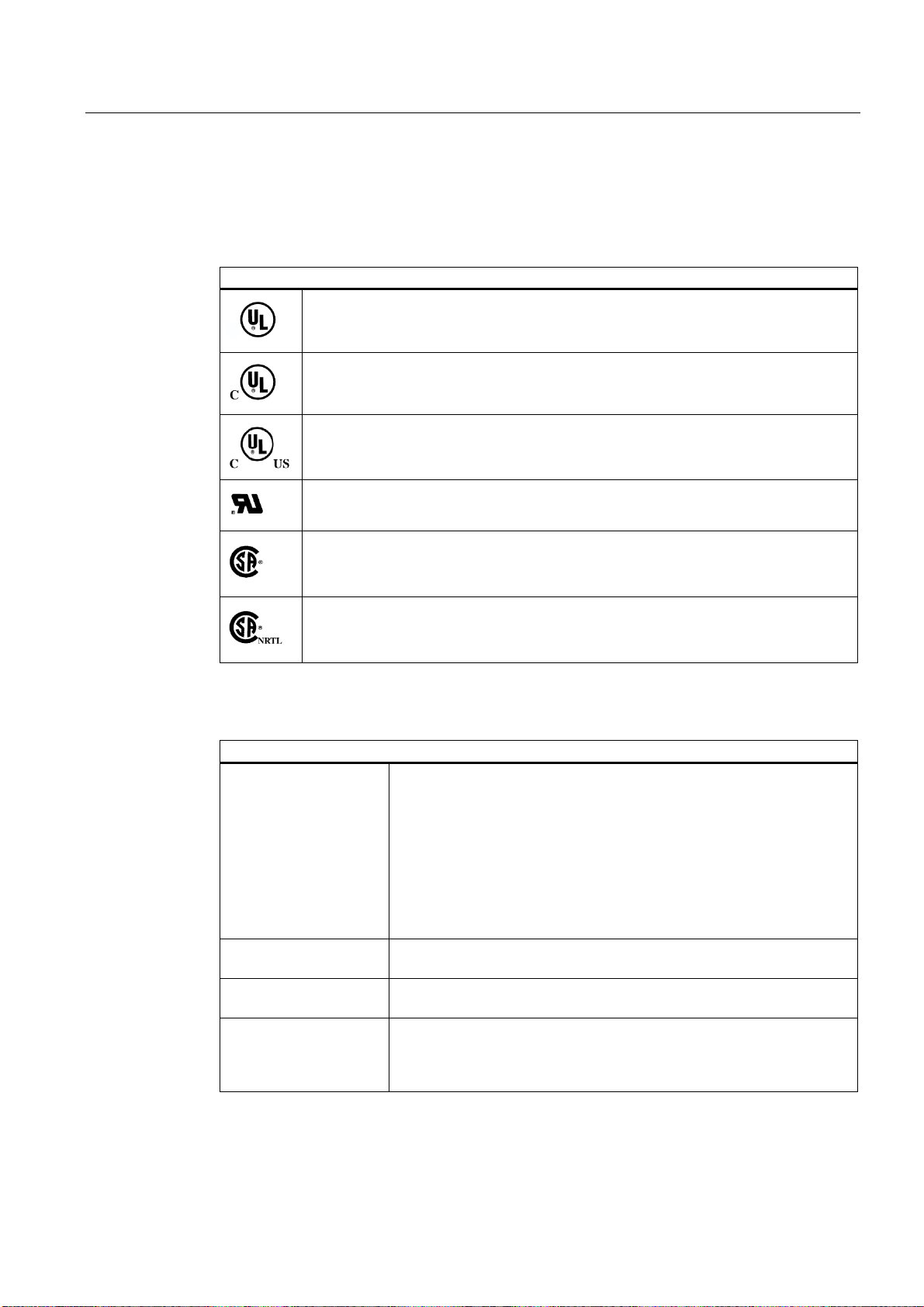
One of the following markings on a device is indicative of the corresponding approval:
Underwriters Laboratories (UL) per UL 60950-1 (I.T.E) or per UL 508 (IND.CONT.EQ)
Underwriters Laboratories (UL) according to Canadian standard C22.2 No. 60950-1
(I.T.E) or C22.2 No. 142 (IND.CONT.EQ)
Underwriters Laboratories (UL) to Standard UL 60950-1, Report E11 5352 and
Canadian Standard C22.2 no. 60950-1 (I.T.E), or to UL508 and C22.2 no. 142
(IND.CONT.EQ)
UL recognition mark
Canadian Standard Association (CSA) per Standard C22.2. No. 60950-1 (LR 81690) or
per C22.2 No. 142 (LR 63533)
EMC
Canadian Standard Association (CSA) to the American Standard UL 60950-1
(LR 81690), or to the UL 508 (LR 63533)
USA
Federal Communications
Commission
Radio Frequency
Interference Statement
Shielded cables Shielded cables must be used with this equipment to maintain compliance
Modifications Changes or modifications not expressly approved by the manufacturer
Conditions of operations This device complies with Part 15 of the FCC Rules. Operation is subject
This equipment has been tested and found to comply with the limits for a
Class A digital device, pursuant to Part 15 of the FCC Rules. These limits
are designed to provide reasonable protection against harmful
interference when the equipment is operated in a commercial
environment. This equipment generates, uses, and can radiate radio
frequency energy and, if not installed and used in accordance with the
instruction manual, may cause harmful interference to radio
communications. Operation of this equipment in a residential area is likely
to cause harmful interference in which case the user will be required to
correct the interference at his own expense.
with FCC regulations.
could void the user's authority to operate the equipment.
to the following two conditions: (1) this device may not cause harmful
interference, and (2) this device must accept any interference received,
including interference that may cause undesired operation.
SIMATIC Box PC 840 V2
Getting Started, Edition 05/2006, A5E00244266-02
A-3
Page 38

Appendix A.3 Service and support
CANADA
Canadian Notice This Class A digital apparatus complies with Canadian ICES-003.
Avis Canadian Cet appareil numérique de la classe A est conforme à la norme NMB-003
du Canada.
A.3 A.3 Service and support
Additional support
If you have any further questions relating to the products described in this documentation,
contact your local representative at the SIEMENS office nearest you.
Find your contact partner at:
http://www.siemens.com/automation/partner
A guide to the technical documentation for the various SIMATIC products and systems is
available at:
http://www.siemens.de/simatic-tech-doku-portal
Training center
Technical support
The online catalog and the online ordering system is available at:
http://mall.automation.siemens.com/
Siemens offers a number of training courses to familiarize you with the SIMATIC automation
system. Please contact your regional Training Center, or the central Training Center in
D90327 Nuremberg.
Phone: +49 (911) 895-3200.
Internet: http://www.sitrain.com
You can reach technical support for all A&D products at:
• Support request form on the web:
http://www.siemens.de/automation/support-request
• Phone: +49 180 5050 222
• Fax: +49 180 5050 223
Further information about our technical support is available in the Internet at
www.siemens.com/automation/service
When you contact the customer support, please have the following information for the
technician on hand:
• BIOS version
• Order No. (MLFB) of the device
• Installed additional software
• Installed additional hardware
SIMATIC Box PC 840 V2
A-4 Getting Started, Edition 05/2006, A5E00244266-02
Page 39

Appendix
A.3 Service and support
Service & support on the Internet
In addition to our documentation, we offer our complete knowledge base on the Internet at.
http://www.siemens.com/asis
There you will find:
• The newsletter which provides the latest information on your products
• Relevant documentation for your application which you can access via the search
function in our service & support database.
• The current BIOS version
• A forum is available for users and specialists from all over the world to exchange
experiences
• Your local Siemens partner for Automation & Drives in our partner database
• Information about on-site service, repairs, spare parts. Lots more is available under
”Services”
You can find the latest information about your device at the following address:
http://support.automation.siemens.com
SIMATIC Box PC 840 V2
Getting Started, Edition 05/2006, A5E00244266-02
A-5
Page 40

Appendix
A.3 Service and support
SIMATIC Box PC 840 V2
A-6 Getting Started, Edition 05/2006, A5E00244266-02
Page 41

Page 42

Siemens AG
Automation and Drives
Industrial Automation Systems
Postfach 4848
90437 NUERNBERG
Federal Republic of Germany
www.siemens.de/automation
,'$(
 Loading...