

Page 1

Preface, Contents
SIMATIC
SIMATIC Box PC 840
Manual
Important Information
Welcome to the SIMATIC Box PC 840
Setting-up and Operating
the SIMATIC Box PC 840
SIMATIC Box PC 840 Expansions
Configuring the SIMATIC Box PC 840
Error Diagnosis
Hardware Information
Reinstallation of the Software
Appendix
1
2
3
4
5
6
7
8
Edition 08/2002
A5E00085984-04
Guidelines for ESD
Technical Specifications
Glossary, Index
A
B
Page 2

Safety Guidelines
This manual contains notices intended to ensure personal safety, as well as to protect the products and
connected equipment against damage. These notices are highlighted by the symbols shown below and
graded according to severity by the following texts:
Danger
!
indicates that death, severe personal injury or substantial property damage will result if proper precautions
are not taken.
Warning
!
indicates that death, severe personal injury or substantial property damage can result if proper
precautions are not taken.
Caution
!
indicates that minor personal injury can result if proper precautions are not taken.
Caution
indicates that property damage can result if proper precautions are not taken.
Notice
draws your attention to particularly important information on the product, handling the product, or to a
particular part of the documentation.
Qualified Personnel
Repair, maintenance and servicing of device only to be carried out by qualified personnel. Qualified
persons are defined as persons who are authorized to commission, to ground and to tag circuits,
equipment, and systems in accordance with established safety practices and standards.
Correct Usage
Note the following:
Warning
!
Trademarks
This device and its components may only be used for the applications described in the catalog or the
technical description, and only in connection with devices or components from other manufacturers which
have been approved or recommended by Siemens.
This product can only function correctly and safely if it is transported, stored, set up, and installed
correctly, and operated and maintained as recommended.
SIMATIC, SIMATIC HMI and SIMATIC NET are registered trademarks of SIEMENS AG.
Third parties using for their own purposes any other names in this document which refer to trademarks
might infringe upon the rights of the trademark owners.
Disclaim of LiabilityCopyright W Siemens AG 2001-2002 All rights reserved
The reproduction, transmission or use of this document or its
contents is not permitted without express written authority.
Offenders will be liable for damages. All rights, including rights
created by patent grant or registration of a utility model or
design, are reserved.
Siemens AG
Organization Group Automation and Drives
Division Systems Engineering
Postfach 2355, DĆ90766 Fürth
Index-2
Siemens Aktiengesellschaft A5E00085984
We have checked the contents of this manual for agreement
with the hardware and software described. Since deviations
cannot be precluded entirely, we cannot guarantee full
agreement. However, the data in this manual are reviewed
regularly and any necessary corrections included in
subsequent editions. Suggestions for improvement are
welcomed.
Siemens AG 2001-2002
Technical data subject to change.
Dokumentation Titel 1Titel 2
EWA 4NEB 780 6023-01
Page 3

Preface
Purpose of the Manual
This manual contains all the information you need for commissioning and using the
SIMATIC Box PC 840.
It is intended both for programming and testing/debugging personnel who commission the device itself and connect it with other units (automation systems, further
programming devices) as well as for service and maintenance personnel who install expansions or carry out fault/error analyses.
Where is this Manual Valid?
This manual is valid for all supplied variations of the SIMATIC Box PC 840 and
describes the state of delivery as of August 2002.
Certifications, Standards and Approvals
Certifications
The device fulfils the following guidelines and certifications:
S EU guideline 73/23/EEC on low voltages
S EU guideline 89/336/EEC on electromagnetic compatibility
S Underwriters Laboratories (UL) to Standard UL 1950
S Canadian Standard Association (CSA) to Standard C22.2 No. 950
Standards and Approvals
The device fulfils the requirements for the CE approval. Approvals for UL and CSA
are available.
Further information on the approvals, certificates, and licenses for your device is
provided in Chapter 1.
Incorporation into the Communications Environment
This manual forms part of the supplied CD “Documentation and Drivers”.
For supplementary instructions on how to handle the software please refer to the
corresponding manuals (for example, the STEP 7 Manual).
SIMATIC Box PC 840 Manual
A5E00085984-04
iii
Page 4

Preface
Structure of the Manual
In Chapters 1 to 4 the manual contains the most important instructions for starting
up and using the programming device of the SIMATIC BOX PC 840.
Chapters 5 to 8 are reference sections you will only require in special cases.
Important Information
This chapter provides information about safety instructions, certificates, directives
and approvals.
Introduction
Before using your device for the first time you should read Chapter 2 to obtain
more information about the SIMATIC Box PC 840 components and their function.
Setting Up and Operation
The basic commissioning steps can be found in Chapter 3. Furthermore, you will
find instructions there on how to work with memory modules for automation
devices and further ports.
Expansion
Chapter 4 describes how to expand your SIMATIC BOX PC 840 (for example,
installation of memory expansions). Please observe the safety instructions.
Configuration
Modifications to the system hardware may make it necessary for you to adapt the
original hardware configuration. Chapter 5 tells how to proceed in this case.
Error/Fault Dignostics
Chapter 6 will tell you how to deal with simple faults that you can diagnose and, in
some cases, eliminate yourself.
Hardware-Informationen
Chapter 7 provides information on the system resources and connecting cables.
Reinstallation of the Software
Chapter 8 shows how to proceed in case you have to reinstall software.
ESD Guidelines
The guidelines for handling electrostatic sensitive devices in Chapter A are of
particular importance for service and maintenance engineers who install
expansions or carry out error analysis with the SIMATIC Box PC 840.
Technical Specifications
Appendix B lists the valid technical specifications for your device. Detailed
information on how your Box PC 840 is equipped can also be found in the BIOS
message (Summary Screen) when your PC is booting up.
Glossary
The glossary explains important terms.
iv
SIMATIC Box PC 840 Manual
A5E00085984-04
Page 5

Alphabetical Index
The index will enable you to quickly find passages in the text pertaining to
important keywords.
Conventions
The abbreviation Box PC oder device is also used within this manual for the product designation SIMATIC Box PC 840.
Further Support
If you have questions related to the use of the products which are not answered in
this manual, please get in touch with your Siemens representative or agent
responsible.
http://www.siemens.com/automation/partner
Preface
Training Centers
Siemens offers a number of training courses to familiarize you with the SIMATIC
S7 automation system. Please contact your regional training center or our central
training center in D 90327 Nuremberg, Germany for details:
Telephone: +49 (911) 895-3200.
Internet: http://www.sitrain.com
SIMATIC Box PC 840 Manual
A5E00085984-04
v
Page 6

Preface
A&D Technical Support
Available worldwide, around the clock:
Johnson City
Nuremberg
Singapore
T echnical Support
Worldwide (Nuremberg)
T echnical Support
Local time: 0:00 to 24:00 / 365 days
Phone: +49 (0) 180 5050-222
Fax: +49 (0) 180 5050-223
E-Mail: adsupport@
GMT: +1:00
Europe / Africa (Nuremberg)
Authorization
Local time: Mon.-Fri. 7:00 to 17:00
Phone: +49 (0) 180 5050–222
Fax: +49 (0) 180 5050-223
E-Mail: adsupport@
GMT: +1:00
The languages of the SIMATIC Hotlines and the authorization hotline are generally German and English.
siemens.com
siemens.com
America (Johnson City)
Technical Support and
Authorization
Local time: Mon.-Fri. 8:00 to 17:00
Phone: +1 (0) 770 740 3505
Fax: +1 (0) 770 740 3699
E-Mail: isd-callcenter@
sea.siemens.com
GMT: –5:00
Asia / Australia (Singapore)
Technical Support and
Authorization
Local time: Mon.-Fri. 8:30 to 17:30
Phone: +65 (0) 740-7000
Fax: +65 (0) 740-7001
E-Mail: simatic.hotline@
sea.siemens.com.sg
GMT: +8:00
vi
SIMATIC Box PC 840 Manual
A5E00085984-04
Page 7

Service & Support on the Internet
In addition to our documentation, we offer our Know-how online on the internet at:
http://www.siemens.com/automation/service&support
where you will find the following:
The newsletter, which constantly provides you with up-to-date information on
your products.
The right documents via our Search function in Service & Support.
A forum, where users and experts from all over the world exchange their
experiences.
Your local representative for Automation & Drives via our representatives
database.
Information on field service, repairs, spare parts and more under “Services”.
Preface
SIMATIC Box PC 840 Manual
A5E00085984-04
vii
Page 8

Preface
viii
SIMATIC Box PC 840 Manual
A5E00085984-04
Page 9

Contents
Preface
1 Important Information 1-1. . . . . . . . . . . . . . . . . . . . . . . . . . . . . . . . . . . . . . . . . . . . . . . . . . .
1.1 Safety Instructions 1-1. . . . . . . . . . . . . . . . . . . . . . . . . . . . . . . . . . . . . . . . . . . . . . .
1.2 Certificates, Directives and Declarations 1-5. . . . . . . . . . . . . . . . . . . . . . . . . . . .
1.3 Certification for the USA, Canada and Autralia 1-7. . . . . . . . . . . . . . . . . . . . . .
1.4 Transport 1-9. . . . . . . . . . . . . . . . . . . . . . . . . . . . . . . . . . . . . . . . . . . . . . . . . . . . . . .
2 Welcome to the SIMATIC Box PC 840 2-1. . . . . . . . . . . . . . . . . . . . . . . . . . . . . . . . . . . .
2.1 Port Side of the Device 2-2. . . . . . . . . . . . . . . . . . . . . . . . . . . . . . . . . . . . . . . . . . .
2.2 Fan Side of Device 2-4. . . . . . . . . . . . . . . . . . . . . . . . . . . . . . . . . . . . . . . . . . . . . .
2.3 Front Port Side of Device 2-5. . . . . . . . . . . . . . . . . . . . . . . . . . . . . . . . . . . . . . . . .
2.4 Drives 2-6. . . . . . . . . . . . . . . . . . . . . . . . . . . . . . . . . . . . . . . . . . . . . . . . . . . . . . . . .
2.4.1 Disk Drive (Depending on the Device Configuration) 2-6. . . . . . . . . . . . . . . . .
2.4.2 LS 240 Drive (Depending on the Device Configuration) 2-6. . . . . . . . . . . . . . .
2.4.3 Hard Disk Drive 2-8. . . . . . . . . . . . . . . . . . . . . . . . . . . . . . . . . . . . . . . . . . . . . . . . .
2.4.4 CD ROM or CD RW/DVD Drive (Depending on the Device Configuration) 2-9
2.5 Backup Battery 2-10. . . . . . . . . . . . . . . . . . . . . . . . . . . . . . . . . . . . . . . . . . . . . . . . .
3 Setting Up and Operating the SIMATIC Box PC 840 3-1. . . . . . . . . . . . . . . . . . . . . . .
3.1 Unpacking and Checking the Scope of Delivery 3-2. . . . . . . . . . . . . . . . . . . . .
3.2 Installing the SIMATIC Box PC 840 3-3. . . . . . . . . . . . . . . . . . . . . . . . . . . . . . . .
3.3 Preparing for Operation 3-9. . . . . . . . . . . . . . . . . . . . . . . . . . . . . . . . . . . . . . . . . .
3.4 Connecting Peripheral Units 3-11. . . . . . . . . . . . . . . . . . . . . . . . . . . . . . . . . . . . . .
3.5 Connecting the SIMATIC Box PC 840 to Other SIMATIC S5 Devices 3-17. . .
3.6 Connecting the SIMATIC Box PC 840 to a SIMATIC S7 Network
(PROFIBUS/MPI) 3-20. . . . . . . . . . . . . . . . . . . . . . . . . . . . . . . . . . . . . . . . . . . . . . .
3.7 Networking the SIMATIC Box PC 840 with Other Stations on PROFIBUS 3-22
3.8 Ethernet (RJ45 Ethernet Port) 3-23. . . . . . . . . . . . . . . . . . . . . . . . . . . . . . . . . . . . .
3.9 Connection under Windows 3-23. . . . . . . . . . . . . . . . . . . . . . . . . . . . . . . . . . . . . . .
4 SIMATIC Box PC 840 Expansions 4-1. . . . . . . . . . . . . . . . . . . . . . . . . . . . . . . . . . . . . . . .
4.1 Opening the Unit 4-2. . . . . . . . . . . . . . . . . . . . . . . . . . . . . . . . . . . . . . . . . . . . . . . .
4.1.1 Prerequisites 4-2. . . . . . . . . . . . . . . . . . . . . . . . . . . . . . . . . . . . . . . . . . . . . . . . . . .
4.1.2 Opening the SIMATIC BOX PC 840 4-3. . . . . . . . . . . . . . . . . . . . . . . . . . . . . . . .
4.1.3 Components Visible after Opening the Unit 4-4. . . . . . . . . . . . . . . . . . . . . . . . .
4.1.4 The Motherboard 4-5. . . . . . . . . . . . . . . . . . . . . . . . . . . . . . . . . . . . . . . . . . . . . . . .
SIMATIC Box PC 840 Manual
A5E00085984-04
ix
Page 10

Contents
4.2 Installing Memory Expansion Submodules 4-7. . . . . . . . . . . . . . . . . . . . . . . . . .
4.3 Replacing the Backup Battery 4-9. . . . . . . . . . . . . . . . . . . . . . . . . . . . . . . . . . . . .
4.4 Installation of Expansion Cards 4-11. . . . . . . . . . . . . . . . . . . . . . . . . . . . . . . . . . . .
4.4.1 Removal and Installation of the Device for Holding Down the Modules 4-12. .
4.4.2 Removal and Installation of an Expansion Module 4-14. . . . . . . . . . . . . . . . . . .
4.5 Removal and Installation of Drives 4-15. . . . . . . . . . . . . . . . . . . . . . . . . . . . . . . . .
4.5.1 Removal and Installation of the Hard Disk Drive 4-15. . . . . . . . . . . . . . . . . . . . .
4.5.2 Removal and Installation of the Floppy/LS240 or CD ROM,
CD RW/DVD Drive Holder 4-17. . . . . . . . . . . . . . . . . . . . . . . . . . . . . . . . . . . . . . . .
4.5.3 Removal and Installation of the Floppy/LS 240 Drive 4-18. . . . . . . . . . . . . . . . .
4.5.4 Removal and Installation of the CD ROM or CD RW/DVD Drive 4-19. . . . . . .
4.6 Removal and Installation of the Power Supply Unit 4-20. . . . . . . . . . . . . . . . . . .
4.7 Removal and Installation of the Bus Board 4-21. . . . . . . . . . . . . . . . . . . . . . . . . .
4.8 Removal and Installation of the Motherboard 4-22. . . . . . . . . . . . . . . . . . . . . . . .
4.9 Removal and Installation of the Device Fan 4-23. . . . . . . . . . . . . . . . . . . . . . . . .
4.10 Processor Change 4-24. . . . . . . . . . . . . . . . . . . . . . . . . . . . . . . . . . . . . . . . . . . . . . .
4.11 Reset Button 4-25. . . . . . . . . . . . . . . . . . . . . . . . . . . . . . . . . . . . . . . . . . . . . . . . . . .
5 Configuring the SIMATIC Box PC 840 5-1. . . . . . . . . . . . . . . . . . . . . . . . . . . . . . . . . . . .
5.1 Changing the Device Configuration with BIOS SETUP 5-2. . . . . . . . . . . . . . . .
5.2 The Main Menu 5-5. . . . . . . . . . . . . . . . . . . . . . . . . . . . . . . . . . . . . . . . . . . . . . . . .
5.3 The Advanced Menu 5-12. . . . . . . . . . . . . . . . . . . . . . . . . . . . . . . . . . . . . . . . . . . . .
5.4 The Security Menu 5-18. . . . . . . . . . . . . . . . . . . . . . . . . . . . . . . . . . . . . . . . . . . . . .
5.5 The Power Menu 5-20. . . . . . . . . . . . . . . . . . . . . . . . . . . . . . . . . . . . . . . . . . . . . . . .
5.6 The Boot Sequence Menu 5-21. . . . . . . . . . . . . . . . . . . . . . . . . . . . . . . . . . . . . . . .
5.7 The Version Menu 5-23. . . . . . . . . . . . . . . . . . . . . . . . . . . . . . . . . . . . . . . . . . . . . . .
5.8 The Exit Menu 5-24. . . . . . . . . . . . . . . . . . . . . . . . . . . . . . . . . . . . . . . . . . . . . . . . . .
5.9 Default Setup Settings 5-25. . . . . . . . . . . . . . . . . . . . . . . . . . . . . . . . . . . . . . . . . . .
6 Error Diagnosis 6-1. . . . . . . . . . . . . . . . . . . . . . . . . . . . . . . . . . . . . . . . . . . . . . . . . . . . . . . .
6.1 Problems When Using Modules from Other Manufacturers 6-2. . . . . . . . . . . .
6.2 The Monitor Remains Dark 6-3. . . . . . . . . . . . . . . . . . . . . . . . . . . . . . . . . . . . . . .
6.3 The Screen Display Does not Appear or Drifts 6-4. . . . . . . . . . . . . . . . . . . . . . .
6.4 No Mouse Pointer Appears on the Screen 6-4. . . . . . . . . . . . . . . . . . . . . . . . . .
6.5 The Clock Time and/or the Date in your PC Is Incorrect 6-5. . . . . . . . . . . . . .
6.6 USB-Device does not Function 6-5. . . . . . . . . . . . . . . . . . . . . . . . . . . . . . . . . . . .
6.7 An Error Message Appears on the Screen 6-6. . . . . . . . . . . . . . . . . . . . . . . . . .
6.8 Self-Test of the SIMATIC Box PC 840 before Booting 6-8. . . . . . . . . . . . . . . .
SIMATIC Box PC 840 Manual
x
A5E00085984-04
Page 11

Contents
7 Hardware Information 7-1. . . . . . . . . . . . . . . . . . . . . . . . . . . . . . . . . . . . . . . . . . . . . . . . . . .
7.1 Current Requirement of the Components (Maximum Values) 7-2. . . . . . . . . .
7.2 Overview of the Components and Ports 7-3. . . . . . . . . . . . . . . . . . . . . . . . . . . .
7.3 System Resources 7-4. . . . . . . . . . . . . . . . . . . . . . . . . . . . . . . . . . . . . . . . . . . . . .
7.4 Monitoring Functions 7-5. . . . . . . . . . . . . . . . . . . . . . . . . . . . . . . . . . . . . . . . . . . . .
7.4.1 Overview 7-5. . . . . . . . . . . . . . . . . . . . . . . . . . . . . . . . . . . . . . . . . . . . . . . . . . . . . . .
7.4.2 Signals on the Front Interface 7-5. . . . . . . . . . . . . . . . . . . . . . . . . . . . . . . . . . . . .
7.4.3 Temperature Monitoring/Indication 7-6. . . . . . . . . . . . . . . . . . . . . . . . . . . . . . . . .
7.4.4 Watchdog (WD) 7-7. . . . . . . . . . . . . . . . . . . . . . . . . . . . . . . . . . . . . . . . . . . . . . . . .
7.4.5 Fan Monitoring 7-8. . . . . . . . . . . . . . . . . . . . . . . . . . . . . . . . . . . . . . . . . . . . . . . . . .
7.5 Ports 7-9. . . . . . . . . . . . . . . . . . . . . . . . . . . . . . . . . . . . . . . . . . . . . . . . . . . . . . . . . .
7.5.1 External Ports 7-9. . . . . . . . . . . . . . . . . . . . . . . . . . . . . . . . . . . . . . . . . . . . . . . . . .
7.5.2 Assignment of the Front Ports on the Motherboard 7-18. . . . . . . . . . . . . . . . . . .
7.5.3 Assignment of the Internal Ports on the Motherboard 7-21. . . . . . . . . . . . . . . . .
7.6 Bus Board 7-30. . . . . . . . . . . . . . . . . . . . . . . . . . . . . . . . . . . . . . . . . . . . . . . . . . . . . .
7.6.1 Design and Mode of Operation 7-30. . . . . . . . . . . . . . . . . . . . . . . . . . . . . . . . . . . .
7.6.2 Port for Motherboard 7-31. . . . . . . . . . . . . . . . . . . . . . . . . . . . . . . . . . . . . . . . . . . . .
7.7 Power Supply (AC) 7-36. . . . . . . . . . . . . . . . . . . . . . . . . . . . . . . . . . . . . . . . . . . . . .
7.8 Power Supply (DC) 7-37. . . . . . . . . . . . . . . . . . . . . . . . . . . . . . . . . . . . . . . . . . . . . .
7.9 Connecting Cables 7-38. . . . . . . . . . . . . . . . . . . . . . . . . . . . . . . . . . . . . . . . . . . . . .
8 Reinstallation of the Software 8-1. . . . . . . . . . . . . . . . . . . . . . . . . . . . . . . . . . . . . . . . . . .
8.1 Restoring the Hard Disk 8-2. . . . . . . . . . . . . . . . . . . . . . . . . . . . . . . . . . . . . . . . . .
8.1.1 Creating Partitions under Microsoft Windows Me 8-2. . . . . . . . . . . . . . . . . . . .
8.1.2 Creating Partitions under Windows 2000/XP 8-3. . . . . . . . . . . . . . . . . . . . . . . .
8.1.3 Creating Partitions under Windows NT 8-4. . . . . . . . . . . . . . . . . . . . . . . . . . . . .
8.2 Installing the Windows Operating System 8-6. . . . . . . . . . . . . . . . . . . . . . . . . . .
8.2.1 Installing the Recovery CD for Microsoft Windows NT 8-6. . . . . . . . . . . . . . . .
8.2.2 Installing the Microsoft Windows Me Operating System 8-7. . . . . . . . . . . . . . .
8.2.3 Installing the Recovery CD for Microsoft Windows Me 8-8. . . . . . . . . . . . . . . .
8.2.4 Installing the Recovery CD for Microsoft Windows 2000 8-9. . . . . . . . . . . . . .
8.2.5 Installing the Recovery CD for Microsoft Windows XP 8-11. . . . . . . . . . . . . . . .
8.3 Installing Drivers and Software 8-13. . . . . . . . . . . . . . . . . . . . . . . . . . . . . . . . . . . .
8.4 Installing and Operating the Burner Software 8-13. . . . . . . . . . . . . . . . . . . . . . . .
8.5 Installing and Operating the DVD Player Software 8-13. . . . . . . . . . . . . . . . . . .
A Guidelines for Handling Electrostatic Sensitive Devices (ESD) A-1. . . . . . . . . . . .
A.1 What Does ESD Mean? A-2. . . . . . . . . . . . . . . . . . . . . . . . . . . . . . . . . . . . . . . . . .
A.2 Electrostatic Charging A-3. . . . . . . . . . . . . . . . . . . . . . . . . . . . . . . . . . . . . . . . . . . .
A.3 Basic Protective Measures against Discharge of Static Electricity A-4. . . . . .
B Technical Specifications B-1. . . . . . . . . . . . . . . . . . . . . . . . . . . . . . . . . . . . . . . . . . . . . . . .
Glossary Glossary-1. . . . . . . . . . . . . . . . . . . . . . . . . . . . . . . . . . . . . . . . . . . . . . . . . . . . . . . . . .
Index Index-1. . . . . . . . . . . . . . . . . . . . . . . . . . . . . . . . . . . . . . . . . . . . . . . . . . . . . . . . . . . . .
SIMATIC Box PC 840 Manual
A5E00085984-04
xi
Page 12

Contents
xii
SIMATIC Box PC 840 Manual
A5E00085984-04
Page 13

Important Information
1.1 Safety Instructions
Caution
!
Installation
The safety instructions given on the reverse of the title page of this manual must
be observed. Before expanding your SIMATIC Box PC 840 refer to Chapter 4 and
read the relevant safety instructions.
This device corresponds to the relevant safety measures according to IEC, EN,
VDE, UL, and CSA. If you have questions about the permissibility of the installation
in the designated environment, please contact our service representative.
Condensation can occur if the device is transported from a cold environment into
the operating area. The device must be dry prior to startup. You must allow for an
acclimatization time of at least twelve hours.
1
Please observe the notes on ambient conditions in Appendix B Technical
Specifications and the installation notes in Section 3.2 of this manual when
installing and operating the device. The device is to be installed so that there is no
danger of it falling or of causing damage to itself or others.
Be sure the fan ventilation slots are open so that a sufficient amount of air can be
drawn in to cool the housing interior.
Warning
!
Take note of the permissible fitting positions without fail when installing the
systems (see Section 3.2).
If the systems are installed in a non-permissible fitting position, the approvals
pursuant to UL 1950, UL 508 and EN60950 are no longer valid!
SIMATIC Box PC 840 Manual
A5E00085984-04
1-1
Page 14

Important Information
Power Connection
Install the cables so that no one can step on them or trip over them. When you
connect the device, adhere to the relevant instructions in Chapter 2 of this manual.
Do not connect or disconnect power supply cables and data transmission lines
during thunderstorms.
In emergency situations (for example, damaged housing, damaged operator
elements, a damaged power supply cable, ingress of liquids or foreign particles),
switch off the device. Disconnect the power plug and inform the responsible
service personnel.
The SIMATIC Box PC 840 must be switched off when you connect or disconnect
peripheral devices (keyboard, mouse, printer, etc.). You can damage the PC if you
do not adhere to these instructions.
Notes for Devices with AC Power Supply
The device is intended for service in grounded electricity supply systems
(TN systems to VDE 0100, part 300, or IEC 364-3).
Service in non-grounded or impedance-grounded supply systems (IT systems) is
not intended.
The power cord should meet the respective local safety requirements.
Check whether the device’s set supply voltage is the same as the local supply
voltage.
This device is equipped with a safety-tested power supply cable. You may connect
this device only to a grounding outlet with a grounding contact.
Make certain that the socket outlet on the device or the grounding contact for the
building wiring system is freely accessible and as near to the device as possible.
The mains switch does not separate the device from the power system. To
establish a complete power separation, you must disconnect the power plug (inlet
connector on the back of the device). This location must be accessible. A central
isolating switch must be present for cabinet mounting.
Notes for Devices with DC Power Supply
The device does not fulfil the power supply connection requirements for a fire
enclosure to EN60950; therefore the mounting must meet the requirements of fire
protection enclosures in this area.
Warnung
!
Only connect the device to 24V DC power supply systems which meet the
requirements of a safe extra-low voltage (SELV); in addition, a protective
conductor must be connected.
The cable cross section has to be adapted to the short circuit current of the 24V
DC power supply unit so that the cable does not cause damages in the event of a
short circuit. Cables with a cross section of a maximum of up to 5 mm2 can be
connected.
1-2
SIMATIC Box PC 840 Manual
A5E00085984-04
Page 15

Country-Specific Information
For the United States and Canada:
In the United States and Canada USA, a CSA or UL-listed power supply cable
must be used.
The male plug is a 5-15 style.
For operation with 120 V:
Use a UL Listed, CSA Labelles Cord Set, consisting of a min. 18 AWG. Type SVT
or STJ three conductor flexible cord, max. 4.5 m (15 feet) in length and a parallel
blade grounding type attachment plug rated 15 A, min 125 V.
For operation with 240 V:
Use a UL Listed, CSA Labelled Cord Set, consisting od a min. 18 AWG. Type SVT
or SJT three conductor flexible cord, max. 4.5 m (15 feet) in length and a tandem
blade grounding type attachment plug, rated 15 A, 250 V.
For operation with 230 V (outside of USA and Canada)
Important Information
Repairs
!
Use a Cord Set consisting of a min 18 AWG cord and grounding type attachment
plug rated 15 A, 250 V. The cord set should have the approviate safety approvals
for the country in which the equipment will be installed and marked.
Only authorized personnel are permitted to repair the SIMATIC Box PC 840.
Warning
Unauthorized opening and improper repairs on the device can result in significant
danger to the user.
Before you open the device, first switch it off and then disconnect the power plug.
Install only system expansion devices provided for this computer. If you install
other expansion devices, you can damage the system or violate the safety
requirements and regulations for radio interference suppression. Contact your
technical support team or where you purchased your PC to find out which system
expansion devices may safely be installed.
If you install or exchange system expansions and damage your
SIMATIC Box PC 840, the warranty becomes void.
The power supply may only be dismantled or exchanged by authorized technical
personnel.
SIMATIC Box PC 840 Manual
A5E00085984-04
1-3
Page 16

Important Information
Battery
There is a battery in this device below the device fan. Batteries may only be
exchanged by technical personnel.
Observe the local regulations on disposal of special waste when disposing of dead
batteries.
Caution
!
There is the danger of an explosion, if the battery is not exchanged as directed.
Replace only with the same type or an equivalent type recommended by the
manufacturer. Dispose of used batteries in accordance with the manufacturer’s
instructions.
Notes on Inserting and Removing Modules (ESG Guidelines)
Modules containing electrostatically sensitive devices (ESDs) can be identified by
the following label:
Please observe and carefully follow the guidelines mentioned below when handling
modules equipped with electrostatically sensitive devices:
Always discharge your body before handling modules equipped with ESDs (for
example, by touching a grounded object).
Devices and tools must be free of static electricity.
Always pull the power plug and disconnect the battery before connecting or
disconnecting modules (containing ESDs).
Touch modules fitted with ESDs by their edges only.
1-4
Never touch wiring posts or printed conductors on modules containg ESDs.
SIMATIC Box PC 840 Manual
A5E00085984-04
Page 17

1.2 Certificates, Directives and Declarations
Notes on the CE Symbol
The following applies to the SIMATIC product described in this manual:
EMC Directive
AC power supply
The devices with AC power supply fulfil the requirements for the EC directive
89/336/EEC on “electromagnetic compatibility” and the following fields of
application apply according to this CE symbol:
Field of Application Requirement For
Emitted
Interference
Residential and commercial areas
and small businesses.
EN 50081-1: 1992 EN 50082-1: 1992
Important Information
Noise Immunity
Industry EN 50081-2: 1993 EN 50082-2: 1995
In addition, the EN 61000-3-2:1995 (harmonic currents) and EN 61000-3-3:1995
(voltage fluctuation and flicker) have been fulfilled.
DC power supply
The devices with DC power supply fulfil the requirements for the EC directive
89/336/EEC on “electromagnetic compatibility” and the following field of application
apply according to this CE symbol:
Field of Application Requirement For
Emitted
Interference
Industry EN 50081-2: 1993 EN 50082-2: 1995
In addition, the EN 61000-3-2:1995 (harmonic currents) and EN 61000-3-3:1995
(voltage fluctuation and flicker) have been fulfilled.
Caution
This is a class A electronic device. This device may cause interference in
residential areas. In this case the user may be asked to take the necessary
precautions.
Noise Immunity
SIMATIC Box PC 840 Manual
A5E00085984-04
1-5
Page 18

Important Information
Low Voltage Directive
This product fulfils the requirements for the EC directive 73/23/EEC on “low
voltage” and was tested to EN60950.
Declaration of Conformity
The EC declarations of conformity and the documentation relating to this are
available to the authorities concerned, according to the above EC directive, from:
Siemens AG
Bereich Automation & Drives
A&D AS RD 4
Postfach 1963
D-92209 Amberg
Tel.: +49 (9621) 80-3283
Fax: +49 (9621) 80-3278
Observing the Setup Guidelines
The setup guidelines and safety instructions given in this electronic manual must
be observed on startup and during operation.
Connecting Peripherals
The requirements regarding noise immunity (EN50082-2:1995) are met when you
connect a peripheral suitable for an industrial environment. Peripheral devices are
only be connected via shielded cables.
ISO 9001 Certificate
The quality assurance system for the whole product process (development,
production, and marketing) fulfills the requirements of ISO 9001 (corresponds to
EN29001: 1987).
This has been certified by the German society for the certification of quality
management systems (DQS).
EQĆNet certificate no.: 1323Ć01
Software License Agreement
The SIMATIC Box PC 840 is shipped with the software already installed. Please
observe the relevant license agreements.
1-6
SIMATIC Box PC 840 Manual
A5E00085984-04
Page 19

1.3 Certification for the USA, Canada and Autralia
(
)
or to the UL508 and C22.2 No. 142 (IND.CONT.EQ)
Security
One of the following markings on a device is indicative of the corresponding
approval:
Underwriters Laboratories (UL) to the UL 1950 Standard (I.T.E)
or to the UL508 (IND.CONT.EQ)
Underwriters Laboratories (UL) to the Canadian Standard C22.2 No. 950
C
C US
(I.T.E) or to the C22.2 No. 142 (IND.CONT.EQ)
Underwriters Laboratories (UL) to Standard UL 1950, Report E11 5352 and to
the Canadian Standard C 22.2 No.950 (I.T.E)
or to the UL508 and C22.2 No. 142
IND.CONT.EQ
UL-Recognition-Mark
Important Information
Canadian Standard Association (CSA) to standard C22.2. No. 950
(LR 81690) or to C22.2 No. 142 (LR 63533)
Canadian Standard Association (CSA) to the American Standard UL 1950
(LR 81690) or to the UL 508 (LR 63533)
NRTL
SIMATIC Box PC 840 Manual
A5E00085984-04
1-7
Page 20

Important Information
EMV
USA
This equipment has been tested and found to comply with the limits for a Class A digital
device, pursuant to Part 15 of the FCC Rules. These limits are designed to provide
reasonable protection against harmful interference when the equipment is operated in a
commercial environment. This equipment generates, uses, and can radiate radio
frequency energy and, if not installed and used in accordance with the instruction manual,
may cause harmful interference to radio communications. Operation of this equipment in a
residential area is likely to cause harmful interference in which case the user will be
required to correct the interference at his own expense.
Shielded cables must be used with this equipment to maintain compliance with FCC regulations.
Changes or modifications not expressly approved by the manufacturer could void the
user’s authority to operate the equipment.
Federal Communications Commission
Radio Frequency Interference Statement
Shielded Cables
Modifications
This device complies with Part 15 of the FCC Rules. Operation is subject to the following
two conditions: (1) this device may not cause harmful interference, and (2) this device must
accept any interference received, including interference that may cause undesired
operation.
Canada
(for devices with DC power supply)
This Class A digital apparatus complies with Canadian ICES-003.
Cet appareil numérique de la classe A est conforme à la norme NMB-003 du Canada.
(for devices with AC power supply)
This Class B digital apparatus complies with Canadian ICES-003.
Cet appareil numérique de la classe B est conforme à la norme NMB-003 du Canada.
Conditions of Operations
Canadian Notice
Avis Canadien
Canadian Notice
Avis Canadien
Australia
(for devices with AC power supply)
This product meets the requirements of the
1-8
AS/NZS 3548 Norm.
SIMATIC Box PC 840 Manual
A5E00085984-04
Page 21

1.4 Transport
Transporting
Despite the fact that the SIMATIC Box PC 840 is of rugged design, its internal
components are sensitive to severe vibrations or shock. You must therefore protect
the PC from severe mechanical stress when transporting it.
Use the original packing material if you have to ship the SIMATIC Box PC 840
from one location to another.
Caution
!
Risk of damage!
When transporting the PC in cold weather, when it may be submitted to extreme
variations in temperature, make sure that there is no moisture (condensation) on
or in the PC.
Important Information
The PC must be allowed to reach room temperature slowly before you switch it on.
If condensation has formed, you should wait approximately 12 hours before
switching on the PC.
SIMATIC Box PC 840 Manual
A5E00085984-04
1-9
Page 22

Important Information
1-10
SIMATIC Box PC 840 Manual
A5E00085984-04
Page 23

Welcome to the SIMATIC Box PC 840
Overview of Chapter
Section Description Page
2.1 Port Side of the Device 2-2
2.2 Fan Side of Device 2-4
2.3 Front Port Side of Device 2-5
2.4 Drives 2-6
2.5 Backup Battery 2-10
2
SIMATIC Box PC 840 Manual
A5E00085984-04
2-1
Page 24
Welcome to the SIMATIC Box PC 840
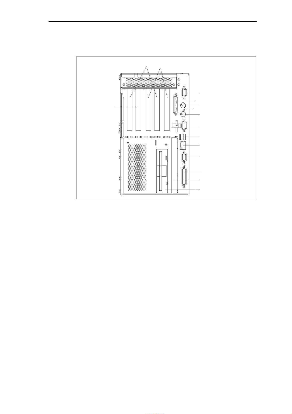
2.1 Port Side of the Device
15
14
13
12
11
10
9
8
7
6
5
4
3
2
1
Figure 2-1 Port Side
1 Floppy Disk Drive (LS240 as an alternative)
Depending on the device configuration a standard floppy disk drive (1.44 Mbytes)
or an LS240 Super disk drive is installed. Floppy disks up to 1.44 Mbytes as well
as Super disks up to 240 Mbytes can be used in LS240 drives.
2 CD ROM, CD RW/DVD Drive
Depending on the device configuration, it can come with a CD ROM or a
CD RW/DVD drive. For example, you can read the electronic manual of the supplied ”Documentation and Drivers” CD with this drive.
3 COM1 V.24 /MODEM /AG
The COM 1 (TTY) port is used to connect, for example, S5 automation units (AG).
The supplied gender changer can be used to convert the port into a 9-pole
standard V.24 port for connecting serial port devices such as modem, mouse or
printer. The line current (TTY) interface is an optional product feature. You change
the connection into a male connector by attaching the gender changer.
2-2
4 PROFIBUS/MPI (optional)
You can connect the Box PC to an S7 automation system or to a PROFIBUS
network via the PROFIBUS/MPI port with galvanic isolation. This interface is an
optional product feature.Electrical isolation through an extra-low voltage safety
circuit (SELV).
SIMATIC Box PC 840 Manual
A5E00085984-04
Page 25

Welcome to the SIMATIC Box PC 840
5 Ethernet
RJ 45-Ethernet connector. Ethernet is a local network with a bus structure for data
communication with a data transfer rate of 10 or 100 megabits per second (Mbps).
6 USB
Universal Serial Bus connector. You can use the USB port to connect external
devices, for example, CD drives, printers, modems as well as mouse and
keyboard. Older operating systems do not support this port.
7 COM2
You can use the serial port 2 (V.24) to connect devices with a serial port such as
modem, mouse or printer.
8 Keyboard
Connection for a PS/2 keyboard.
9 Reset
The reset button can be actuated with a thin pen (for example, an opened up paper
clip). If you actuate the button, a hardware reset is triggered. The PC restarts. Data
loss is possible with a hardware reset.
10 Mouse
PS/2 socket for connecting a PS/2 mouse.
11 LPT1/Printer
The parallel port connection for devices with parallel port, for example, printer.
12 VGA
You can connect an external VGA monitor to this connector.
Caution
Ensure that you use shielded cables and metal plugs to connect the peripheral
units; if this is not done, the approval for operation will be invalid! Screw down the
plugs of the interface cables to the PC housing by means of a screwdriver. You
thereby improve the electrical shielding.
13 PCI Slots
Internal slots for expansion modules.
14 PCI/ISA Slots
Internal slots for expansion modules.
15 ISA Slot
Internal slot for an ISA expansion module.
If expansion modules have been inserted in the PC, there are additional ports.
Please refer to the description of the respective module for their purpose.
SIMATIC Box PC 840 Manual
A5E00085984-04
2-3
Page 26
Welcome to the SIMATIC Box PC 840
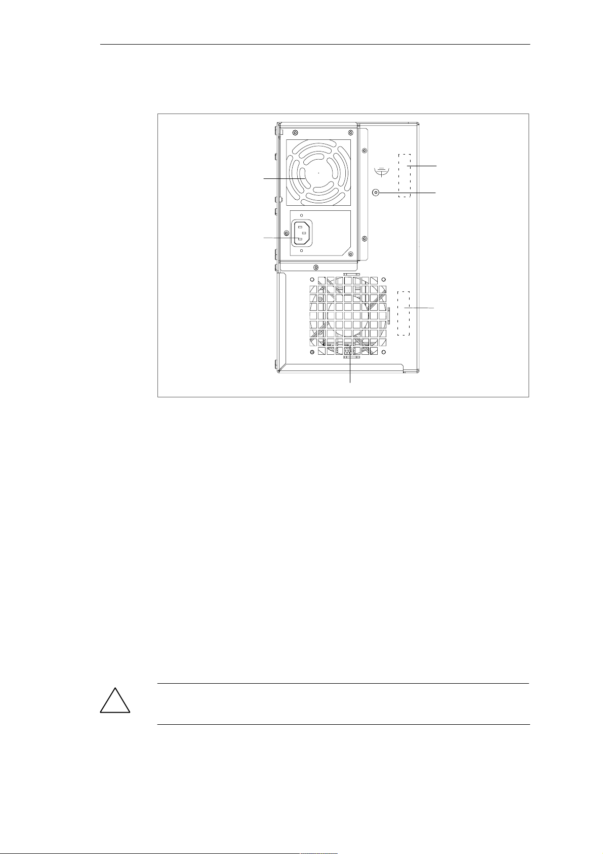
2.2 Fan Side of Device
5
6
4
3
2
1
Figure 2-2 Fan Side
1 Device Fan
Here are openings for device ventilation.
2 Type Label
You can find the order number and the serial number (F-No.) of your device on the
type label.
3 Equipotential Grounding Connection
The connection with the equipotential grounding on the system housing to the
central earth terminal of the cabinet or the unit into which the computer is fitted,
ensures that faults arising from external power supply cables, signalling cables or
cables to peripheral units are diverted.
4 Certificate of Authenticity with Product Key
When reinstalling software you need the Microsoft Windows “Product Key” on the
“Certificate of Authenticity”.
5 Fan of Power Suppy
Here are openings for device ventilation.
6 AC/DC Power Supply Connector
Device socket for non-heating appliances with AC power supply or terminal screw
with DC power supply.
2-4
Caution
!
The air venting slots for incoming and outgoing air must not be obstructed.
Otherwise, there is a risk of overheating.
SIMATIC Box PC 840 Manual
A5E00085984-04
Page 27
2.3 Front Port Side of Device
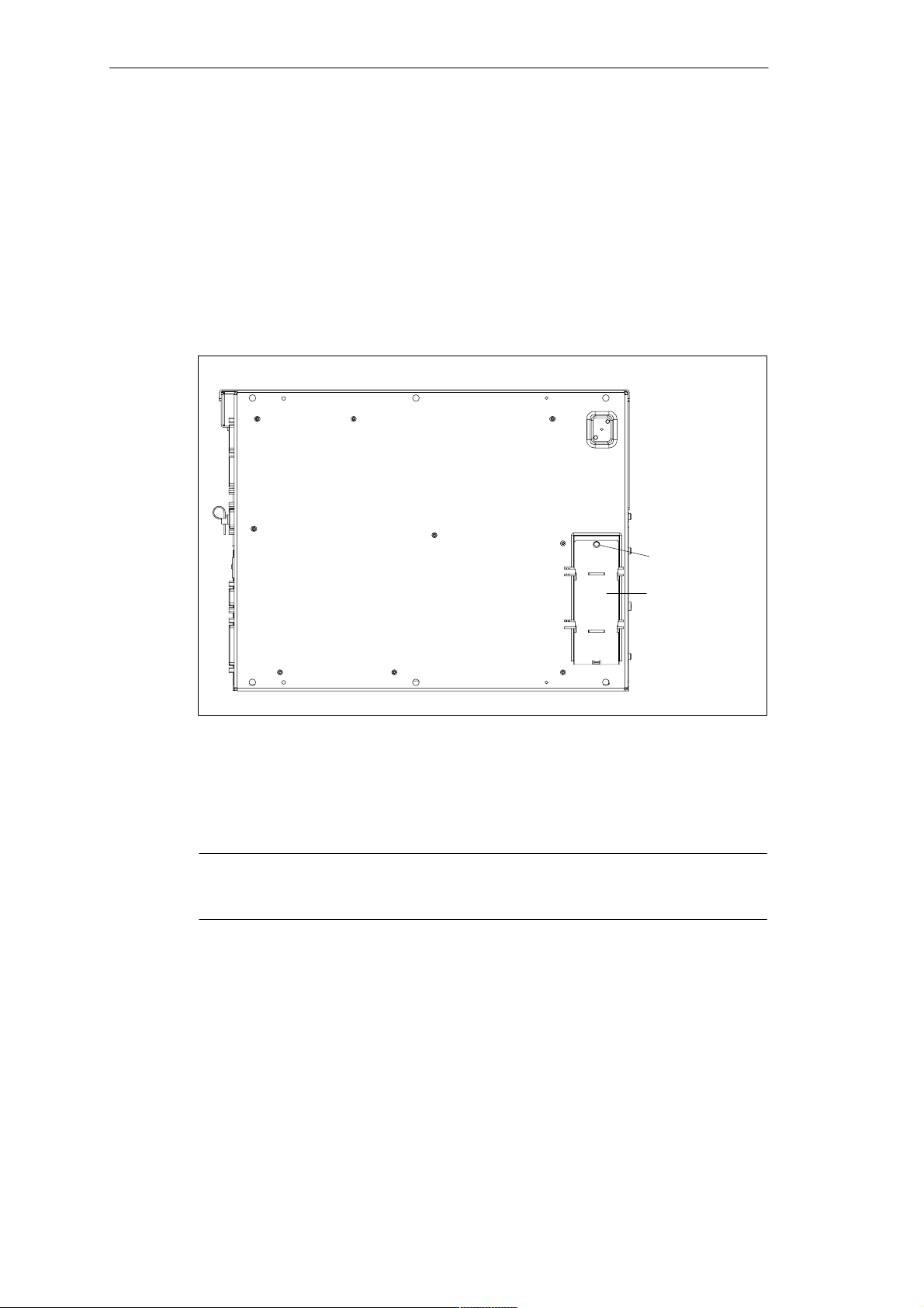
Front Ports
The front ports are located behind the cover on the rear side of the device. They
are used for connection of the front elements:
I/O port for the connection of front components
LVDS display port
Welcome to the SIMATIC Box PC 840
Screw
Cover
Figure 2-3 Front Ports
The front ports can be accessed as follows:
1. Undo the screw on the cover.
2. Pull the cover out of the guide. The front ports are now accessible.
Notice
Keep the cover and the screw for reuse.
SIMATIC Box PC 840 Manual
A5E00085984-04
2-5
Page 28

Welcome to the SIMATIC Box PC 840
2.4 Drives
The SIMATIC Box PC 840 is equipped as standard with a 3.5” disk drive or an
LS240 drive and a 3.5” hard disk drive.
2.4.1 Disk Drive (Depending on the Device Configuration)
You can store programs and data on diskettes with the disk drive and load them
from diskettes into the SIMATIC Box PC 840.
Diskette Types
You can use following diskettes:
Double Sided Double
Density Diskette
3.5 in. 3.5 in. 3.5 in.
720 Kbytes 1.44 Mbytes (135 TPI) 240 Mbytes
Caution
!
Risk of data loss!
When the green access LED of the disk drive is lit, the ejector may not be
actuated.
Double Sided High
Density Diskette
LS240-Superdisks
2.4.2 LS 240 Drive (Depending on the Device Configuration)
The Box PC can be equipped with an LS 240 drive as an alternative to a floppy
disk drive.
Larger volumes of data can be stored on LS 240 data carriers than on a 1.44 MBytes floppy disk drive. The LS 240 has the following features:
– it is compatible with a 1.44 MB floppy disk drive, i.e. 1.44 MB or 120 MBytes
disks can also be processed.
– an LS 240 data carrier has a maximum data volume of 240 Mbytes.
– the LS 240 drive is connected via an ATAPI (IDE) port.
2-6
SIMATIC Box PC 840 Manual
A5E00085984-04
Page 29
Handling Disks with the LS 240 Drive
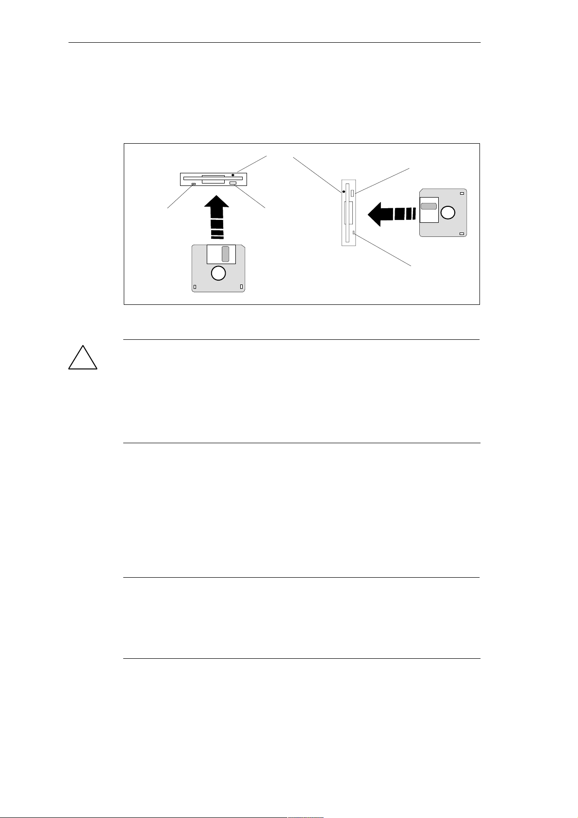
Depending on the fitting position, the disks are inserted into the disk drive as
illustrated below:
Access hole for emergency ejection (only LS240)
Welcome to the SIMATIC Box PC 840
Ejector
Access LED
Figure 2-4 Handling Disks
Caution
!
Risk of data loss!
When the green access LED of the LS 240 drive is lit, the ejector may not be
actuated.
LS 120 drives are very sensitive to shocks of a non-permissible level. Shocks
during operation can lead to damage to the drive or the data carrier. You can find
the permissible values in the technical specifications in Appendix B.
Information on the LS240 Disk Drive
Ejector
Access LED
Restrictions
P-Tools under STEP 5
Data cannot be edited in PCP/M format on the LS240 drive using P Tools under
STEP 5.
Notice
When using the P tools supplied with STEP 5 (editing PCP/M files) take note that
these are no longer completely supported by the Windows Me, Windows 2000
Professional and Windows XP Professional operating systems as well as the
LS240 disk drives. P tools should be used under MS-DOS, Windows 3.x or
Windows 95 and require a standard 1.44 MB disk drive.
SIMATIC Box PC 840 Manual
A5E00085984-04
2-7
Page 30

Welcome to the SIMATIC Box PC 840
Authorization with AuthorsW V2.x
Use AuthorsW to authorize STEP 7 and other SIMATIC components. When using
PGs start the taskbar under Start > Simatic > AuthorsW.
Usage Notes for LS240 Superdisks
Floppy disks up to 1.44 Mbytes as well as Superdisks up to 240 Mbytes can be
used in LS240 drives.
Track density for Superdisks is10 mm compared with the 120 mm of conventional
disks.
The LS240 drive recognizes when a Superdisk is in the drive and switches to the
higher capacity.
Due to their higher storage capacity, Superdisks are more sensitive to dirt,
temperature and shock than conventional diskettes.
Notice
In order to achieve a reliable operation and high data security, please note the
following during use:
Store and transport the Superdisk in the protective cassette included. This will
keep dust and dirt from the disk.
Remove Superdisk from the drive when it is not being read or written to keep
dirt particles away from the disk. Do not expose the disk to unnecessarily high
operating temperatures.
Notice
If possible avoid vibration of the device, when using Superdisks. Superdisks are
more sensitive to vibration as a result of their high track density.
Emergency Removal:
When the device is switched off, the disk can be forced out by using a pin (for
example, an opened up paper clip).
2.4.3 Hard Disk Drive
The hard disk drive is used for the storage of large quantities of data. it is fitted in a
mounting which is easily exchangeable and damped against vibration.
2-8
Caution
!
Drives are sensitive to vibrations and shock. Any vibrations occurring during
operation can lead to loss of data or damage to the drive.
If you intend transporting the unit, switch it off, and wait until the drive has come to
rest (about 20 seconds) before you move it.
SIMATIC Box PC 840 Manual
A5E00085984-04
Page 31

Welcome to the SIMATIC Box PC 840
2.4.4 CD ROM or CD RW/DVD Drive (Depending on the Device Configuration)
Depending on the device configuration, a CD ROM or a CD RW/DVD drive is fitted
in the SIMATIC Box PC 840.
Operation
When the open/close button is pressed, the CD/DVD tray is travelled out with a
slight delay. Insert the CD/DVD with the labelling facing forwards into the tray. The
CD/DVD tray is retracted automatically, when the tray is pressed briefly or the the
Open/Close button is pressed.
By briefly pressing the eject button, the drawer springs out slightly. You can
remove the CD/DVD.
Emergency removal
When the device ist switched off, the disk can be forced out by using a pin (for
example, a opened up paper clip).
Notice
After the drawer has been closed, the CD/DVD is tested and the access display
light on the drive starts to flash:
– If the access LED flashes continually, the CD/DVD is faulty but can still be
read,
– If the access LED flashes several times and then remains lit, the CD/DVD
you have inserted is defective and cannot be read.
– normally the access LED is lit when reading the CD/DVD.
Caution
CD-ROM or CD-RW/DVD drives are sensitive to vibrations and shock. Any vibrations occuring during operation can lead to damage to the drive or CD/DVD.
The burning operation with the CD/DVD drive is only permissible under an
ambient temperature between +5C and +40C.
Additional Software
To be attain the full functionality of the CD RW/DVD drive, additional software
(DVD player or burner software) is necessary. You can find it on the CD included in
the delivery of the device. To install the software place the CD in the drive and follow the instructions on the screen.
SIMATIC Box PC 840 Manual
A5E00085984-04
2-9
Page 32

Welcome to the SIMATIC Box PC 840
Vorsicht
Risk of data error when burning a CD-RW!
The quality of recordable CDs vary considerably, data error can therefore not be
completey ruled out when writing a CD, even when no error message is displayed.
Correctly written data can only be guaranteed by an additional comparison with
the source data. To ensure an error-free copying process do a data comparison
after every burning session.
2.5 Backup Battery
A backup battery (3.6 V lithium battery) powers the hardware clock even after the
programming device is switched off.
In this device there is a battery below the device fan. Batteries may only be
exchanged by technical personnel. Observe the local regulations on the disposal of
special waste when disposing of dead batteries. Refer to Section 4.3 for exchanging the backup battery.
Caution
!
!
There is the danger of an explosion if the battery is not exchanged as directed.
Replace only with the same type or an equivalent type recommended by the
manufacturer. Dispose of used batteries in accordance with the manufacturer’s
instructions.
Warning
Risk of severe personal injury or property damage, danger of release of harmful
substances.
There may be a danger of explosion if the battery is not handled properly.
Incorrect disposal of used batteries can cause the release of harmful substances.
Do not throw a new or discharged lithium battery into an open fire, do not solder
onto the cell container. Do not recharge the battery, do not open the battery by
force.
The correct lithium battery is available from Siemens (order no.: W79084-E1003-B1).
Return used batteries to the manufacturer/recycler or dispose of them according to
local regulations.
2-10
SIMATIC Box PC 840 Manual
A5E00085984-04
Page 33

Setting Up and Operating the SIMATIC Box PC 840
Chapter Overview
Section Description Page
3.1 Unpacking and Checking the Scope of Delivery 3-2
3.2 Installing the SIMATIC Box PC 840 3-3
3.3 Preparing for Operation 3-9
3.4 Connecting Peripheral Units 3-11
3.5 Connecting the SIMATIC Box PC 840 to Other SIMATIC S5
Devices
3.6 Connecting the SIMATIC Box PC 840 to a SIMATIC S7 Network
(PROFIBUS/MPI)
3.7 Networking the SIMATIC Box PC 840 with Other Stations on
PROFIBUS
3.8 Ethernet (RJ45 Ethernet Port) 3-23
3.9 Connection under Windows 3-23
3
3-17
3-20
3-22
SIMATIC Box PC 840 Manual
A5E00085984-04
3-1
Page 34

Setting Up and Operating the SIMATIC Box PC 840
3.1 Unpacking and Checking the Scope of Delivery
Unpacking the SIMATIC Box PC 840
Unpack your SIMATIC Box PC 840 as follows:
1. Remove the Box PC from the packaging.
2. Do not throw the original packing away. Keep it in case you have to transport
the unit again sometime in the future.
3. Please keep the documentation in a safe place. It is required during the initial
start up and is part of the device.
4. Check the packing and its contents for any shipping or transport damage.
5. Check with the packing list to make sure no components are missing. Also
check the accessory parts, which you can order separately.
6. Please inform your local dealer of any shipping or transport damages and of
outstanding items indicated on the packing list.
Recording the Serial Number and the Ethernet address
7. Enter the serial number and the Ethernet address of your PC in the table
below. You can find the serial number on the type label on the fan side. The
Ethernet address can be found in the BIOS setup settings in the main menu
under the ’Hardware Options’ function.
The device can precisely be identified with the help of these numbers in case of
repairs or theft.
Enter the Microsoft Windows “Product Key” from the “Certificate of
Authenticity”
8. Enter the Microsoft Windows “Product Key” from the “Certificate of Authenticity”
(COA) in the table. You will find the “Product Key” on the device. You need the
Windows “Product Key” if you want to reinstall the operating system.
Serial number
Order No.
Microsoft Windows Product Key
Ethernet Address
3-2
SIMATIC Box PC 840 Manual
A5E00085984-04
Page 35

Setting Up and Operating the SIMATIC Box PC 840
3.2 Installing the SIMATIC Box PC 840
The SIMATIC Box PC 840 can be operated in all the usual fitting positions. It is
particularly suitable for fitting in consoles, switch boards and control panels.
The SIMATIC Box PC 840 with AC power supply meets the requirements for a
fire enclosure to EN60950. it can therefore be fitted without an additional fire
enclosure.
The SIMATIC Box PC 840 with DC power supply is an open device (left device
side); therefore the mounting must meet the requirements of a fire enclosure.
Warnung
!
Only connect the device to 24V DC power supply systems which meet the
requirements of a safe extra-low voltage (SELV); in addition, a protective
conductor must be connected.
The cable cross section has to be large enough that the Box PC will not be
damaged by the cables when there is a short circuit.
Please note the following points when installing the PC:
Avoid extreme ambient conditions as far as possible. Protect your PC from
dust, moisture, and heat.
Keep the PC out of direct sunlight.
Mount the PC as safely as possible to prevent any danger (for example, by
falling over).
The clearance around the housing must be at least 100 mm, so that the PC is
sufficiently ventilated.
Make certain that the ventilation slots for the housing are not covered.
Observe the permissible fitting positions without fail when installing the
systems.
Warning
!
If the systems are installed in a non-permissible fitting position, the approvals
pursuant to UL 1950, UL 508 and EN60950 are no longer valid!
SIMATIC Box PC 840 Manual
A5E00085984-04
3-3
Page 36
Setting Up and Operating the SIMATIC Box PC 840
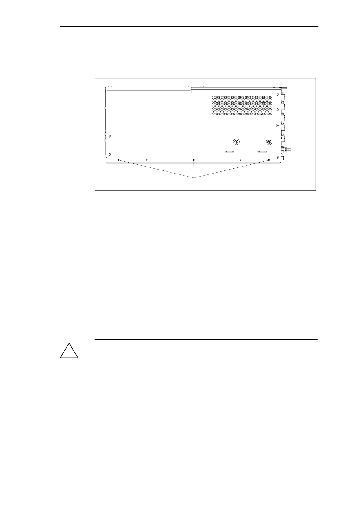
Depending on the configuration of the device, two mounting brackets are included
in the scope of delivery. You can attach these to the housing with 6 screws (M3x6).
M3 thread, max. depth of engagement 5 mm
Figure 3-1 Screw Connection Points for Mounting Brackets (Cover Side Downwards)
Instructions for Wall or Ceiling Installation
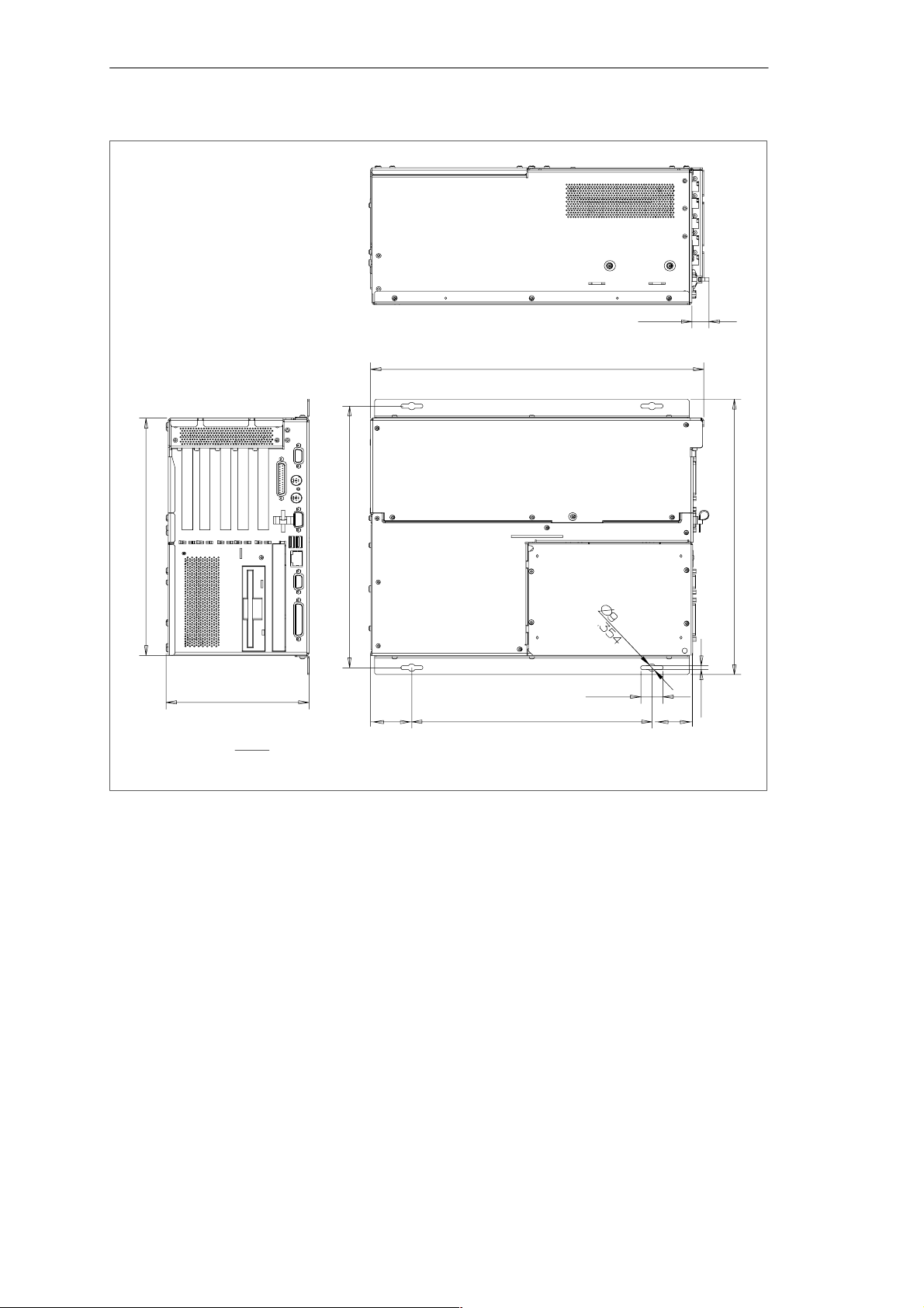
To install the SIMATIC Box PC 840 in a concrete wall or ceiling proceed as follows:
1. Fix the mounting brackets to the housing of the PC.
2. Drill four holes of 8 mm diameter and 60 mm depth into the wall or ceiling. You
will find the required dimension drawings on the following pages.
3. Insert the concrete plugs (8 mm diameter and 50 mm long) into the drill holes.
4. Fix the PC with four screws (4 mm diameter and 50 mm long).
In a plasterboard wall or ceiling (min. 13 mm thick), drill holes of 14 mm diameter
and fasten the PC with four anchors (4 mm diameter and 50 mm long).
In a metal sheet wall or ceiling (min. 2 mm thick), drill holes of 5 mm diameter and
fasten the PC with four screws (4 mm diameter and min. 15 mm long).
Warning
!
The installer must verify that the wall or ceiling can support four times the full load
of the SIMATIC Box PC 840 (with mounting brackets and additional PC cards).
The total weight is approx. 10 kg.
3-4
SIMATIC Box PC 840 Manual
A5E00085984-04
Page 37
Setting Up and Operating the SIMATIC Box PC 840
20,31
.800
388,5
15.295
285
11.220
166,4
6.551
Measuring units:
mm
Inch
314,3
12.374
46,5
1.83
280
11.024
26
1.024
Figure 3-2 Dimension Drawings for Fitting in Control Panel with Installation Angle
46,5
1.83
331
13.032
5
197
SIMATIC Box PC 840 Manual
A5E00085984-04
3-5
Page 38
Setting Up and Operating the SIMATIC Box PC 840
20,31
.800
388,5
15.295
375
14.764
285
11.220
Measuring units:
166,4
6.551
mm
Inch
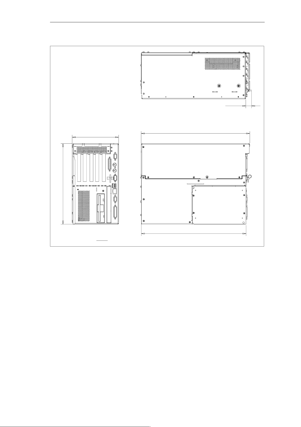
Figure 3-3 Dimension Drawings for Fitting in Control Panel without Installation Angle
3-6
SIMATIC Box PC 840 Manual
A5E00085984-04
Page 39
Setting Up and Operating the SIMATIC Box PC 840
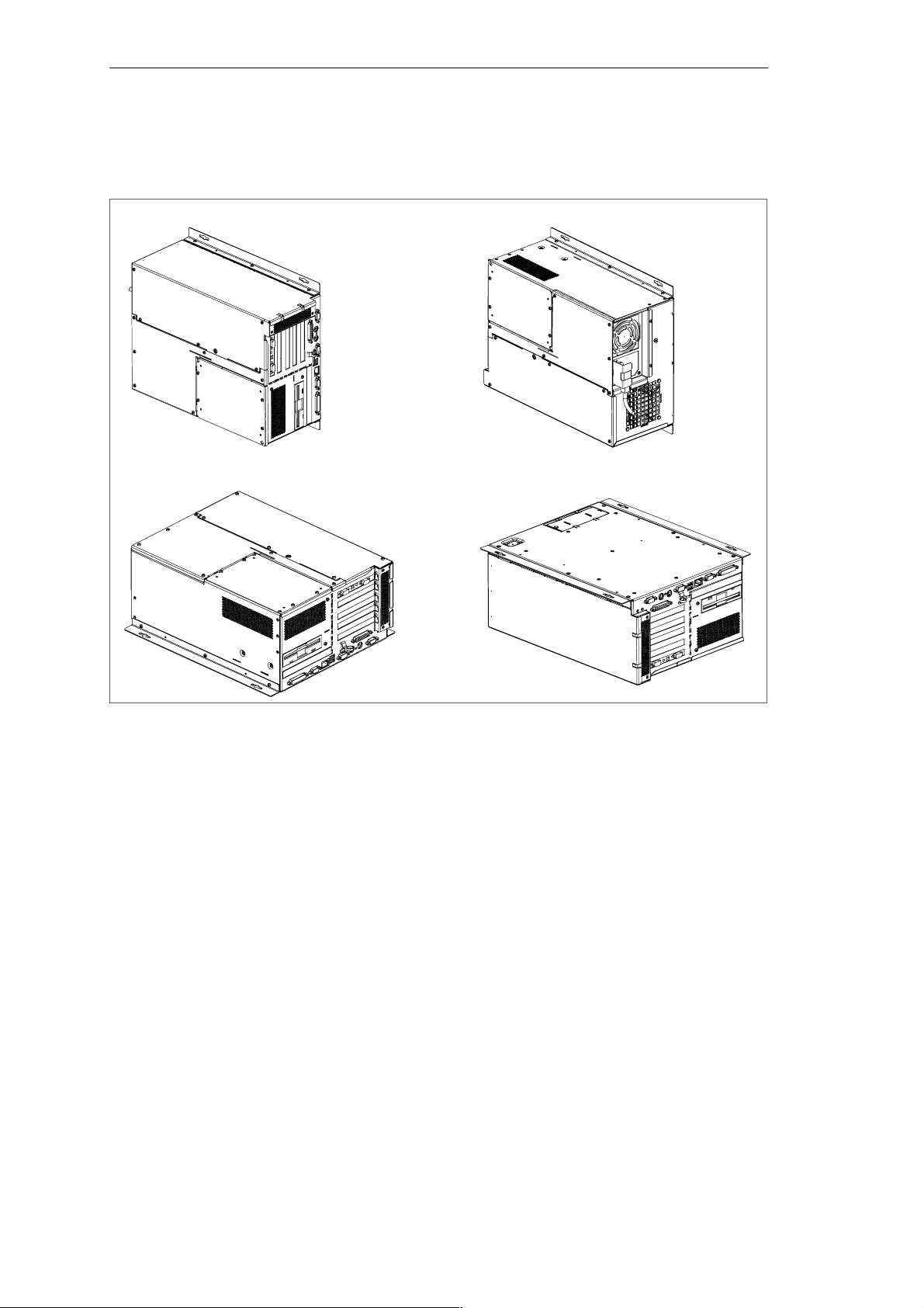
Permissible Fitting Positions of the PC to UL1950/EN60950/CSA22.2 No. 950
An inclined position of ± 20 is allowed in each of the permissible fitting positions.
Position 1 (Preferred Position)
Position 3 (Desktop) Position 4 (Ceiling) **)
Position 2 *)
Figure 3-4 Permissible Fitting Positions of the PC with Floppy Disk Drive
*) not permissible for installed LS240 Drive
**) not permissible for installed CD ROM, CD RW/DVD Drive or LS 240 Drive
SIMATIC Box PC 840 Manual
A5E00085984-04
3-7
Page 40
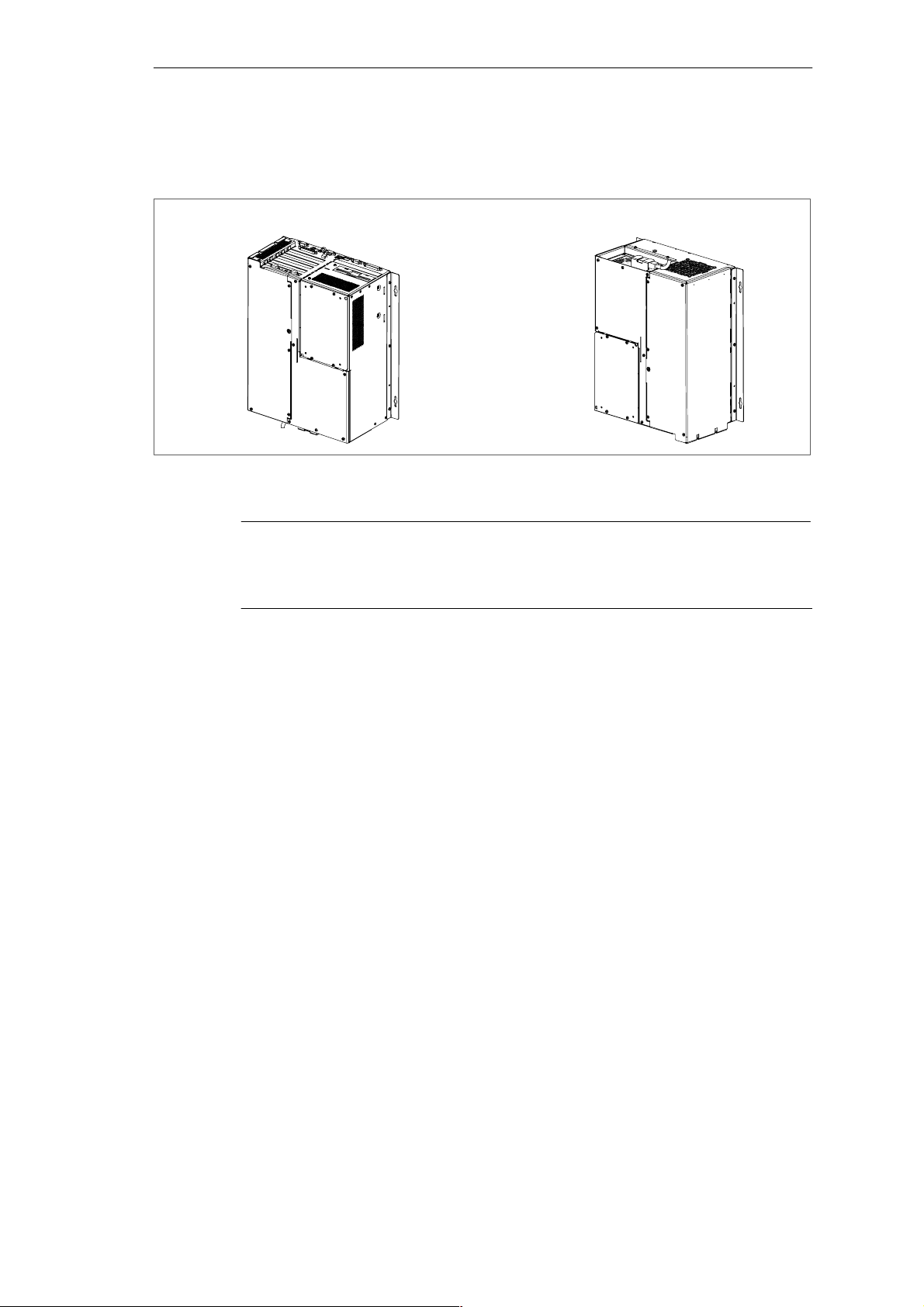
Setting Up and Operating the SIMATIC Box PC 840
Additional Permissible Fitting Positions of the PC to UL508/CSA 22.2 No. 142
An inclined position of ±15 is allowed in each of the permissible fitting positions.
Position 5
(Fan Side Down) **)
Figure 3-5 Additional Permissible Fitting Positions
**) not permissible for installed CD ROM, CD RW/DVD Drive or LS 240 Drive
Position 6
(Port Side Down) **)
Caution
The fitting position with the fan side down is only permitted with additional
precautions because warmed air is drawn down against the convection current,
possibly causing a build-up of heat.
3-8
SIMATIC Box PC 840 Manual
A5E00085984-04
Page 41
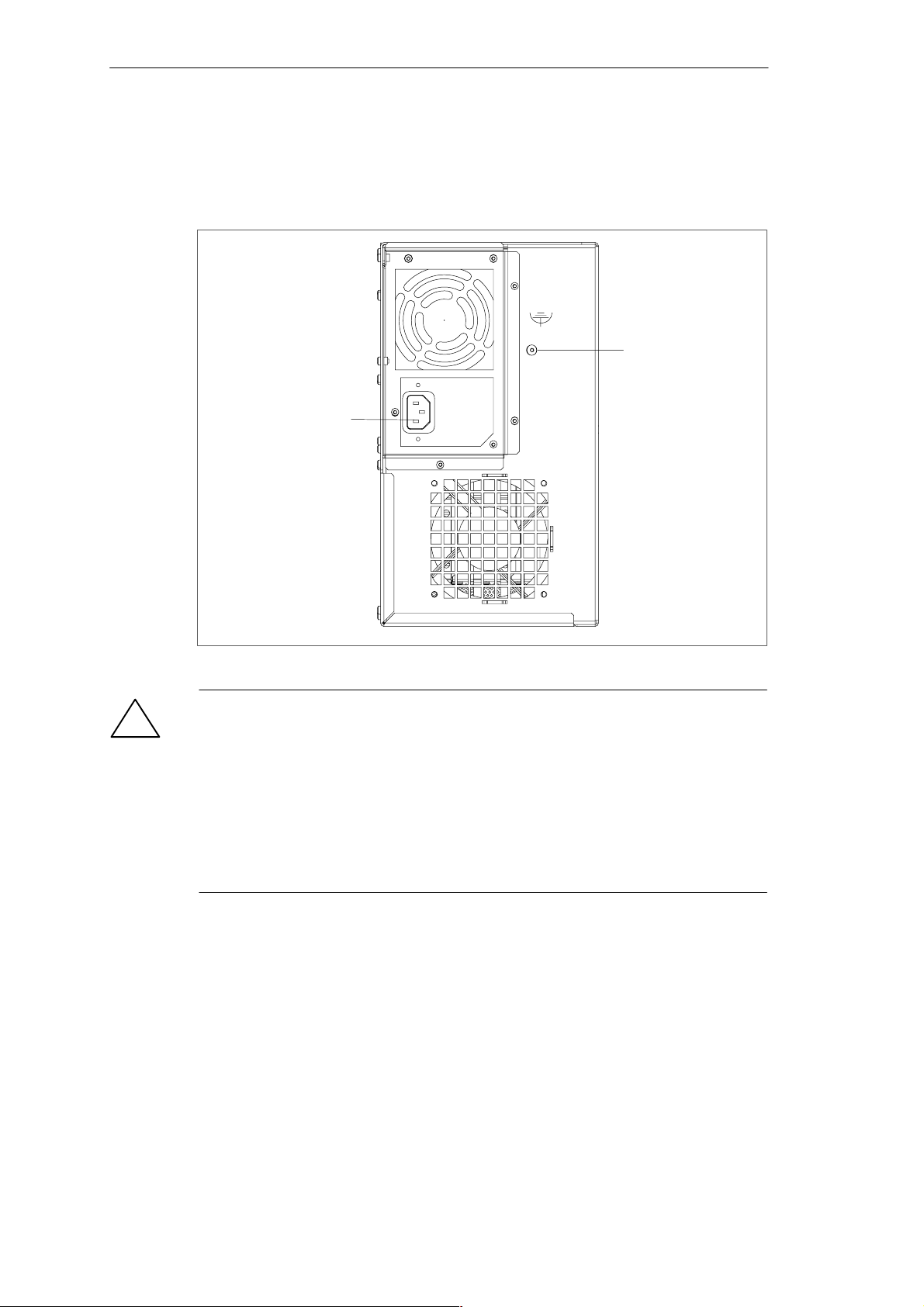
3.3 Preparing for Operation
Connection to the Power Supply Unit
Device socket for
non-heating appliances
with AC supply or
terminal screw with
DC supply
Setting Up and Operating the SIMATIC Box PC 840
Equipontential
grounding connection
Figure 3-6 Connection to the Power Supply Unit
Caution
!
The SIMATIC Box PC 840 with AC power supply is equipped with a safety-tested
mains cable and may only be connected to a grounded grounding outlet.
Make sure that the socket on the device or the grounding outlet of the building
installation is easily accessible and as near as possible to the device.
The SIMATIC Box PC 840 has no mains switch. The mains plug must be pulled
out for complete mains separation. This point must be easily accessible.
If the PC is installed in a cabinet, there must be a central mains disconnector.
The AC power supply unit of the SIMATIC Box PC 840 is designed for 120/240V
systems. The power supply unit has a long-range input. It is not necessary to adjust the voltage span.
The DC power supply unit of the SIMATIC Box PC 840 is designed for
24 V systems.
SIMATIC Box PC 840 Manual
A5E00085984-04
3-9
Page 42

Setting Up and Operating the SIMATIC Box PC 840
Warnung
!
Only connect the device to 24V DC power supply systems which meet the
requirements of a safe extra-low voltage (SELV); in addition, a protective
conductor must be connected.
Optionally, one of these power supplies is installed.
Equipotential Measures
Low-impedance ground connections ensure that faults arising from external power
supply cables, signalling cables or cables to peripheral units are diverted.
Therefore connect the equipotential grounding connection on the system housing
to the central earth terminal of the cabinet or the unit, into which the computer is
fitted, in such a way that it has low impedance (large surface area, large contacts).
The minimum cross section should not be less than 5 mm2.
The connection is on the fan side and is identified by the symbol:
Connecting and Switching on the SIMATIC Box PC 840
Before you connect the SIMATIC Box PC 840 to the mains, the peripheral units
must be connected.
1. Insert the connector cable of the peripheral units into the corresponding sockets
on the port side of the SIMATIC Box PC 840 (see Section 3.4.)
2. Connect the device to the mains.
3. The device is now ready for power supply operation and is now in service.
Switching off the SIMATIC Box PC 840
Before switching off the Box PC 840, you have to shut down the operating system
to avoid loss of data. The Box PC has no mains switch and can only be switched
off after being disconnected from the mains.
Note
If you are working with Windows, always use Start > Shut down in the task bar
for switching off your Box PC.
3-10
SIMATIC Box PC 840 Manual
A5E00085984-04
Page 43
Setting Up and Operating the SIMATIC Box PC 840
3.4 Connecting Peripheral Units
Notice
When connecting peripheral units, ensure that the components have industrial
capability.
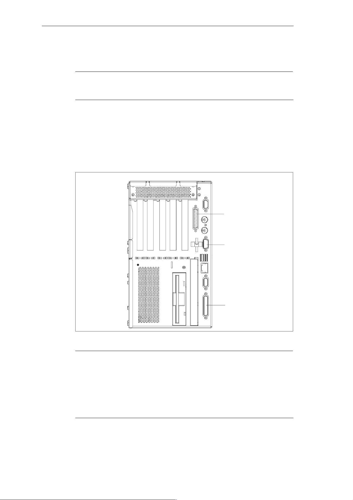
Connecting the Printer to the Parallel Port
Proceed as follows to connect your printer:
1. Separate the Box PC from the mains and switch off the printer.
2. Plug the printer cable into the LPT1 parallel port.
3. Connect the printer cable to the printer.
4. Screw the connector tight at the interface port.
LPT 1
socket (parallel)
COM 2
port (serial)
COM 1
socket (serial)
Figure 3-7 Position of the Printer Ports
Caution
Switch the unit off before connecting the parallel printer to the LPT 1 port (the
printer should also be switched off).
Make sure that you use the correct port. If you use the wrong port or wrong
connecting cables, the port may be damaged.
Before plugging in the cables, the electrostatic charge of your body, the unit, and
the cables must be equalized. To do this, touch the mounting plate for the ports on
the left-hand side of the unit. Only use original connecting cables.
SIMATIC Box PC 840 Manual
A5E00085984-04
3-11
Page 44
Setting Up and Operating the SIMATIC Box PC 840
Connecting the Printer to the Serial Port
You can also connect your printer to the SIMATIC Box PC using a serial COM port.
You will find information on how to adapt and set your port and which connecting
cable you require in the description of your printer.
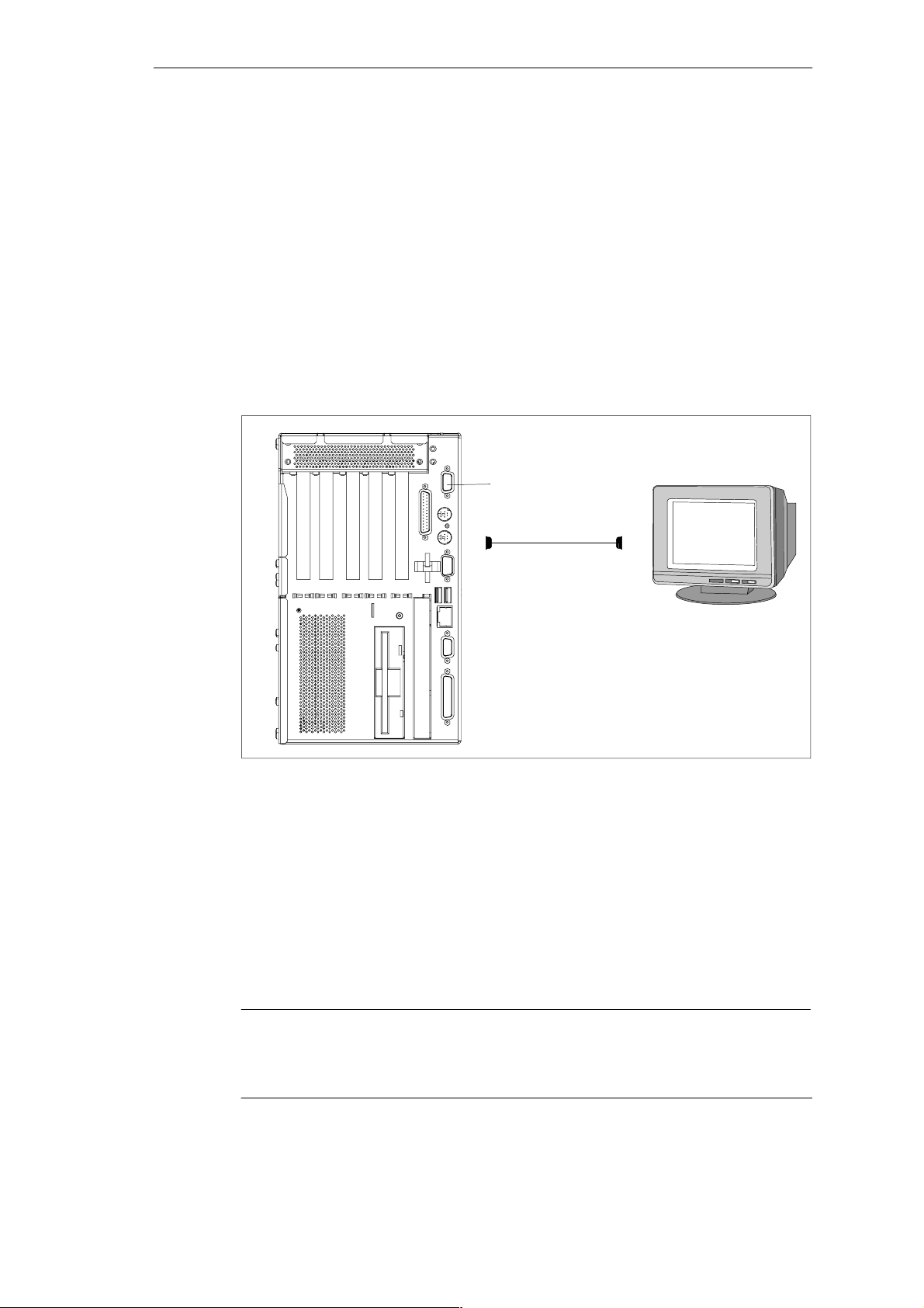
Connecting Monitors
You connect external multisynchronous monitors using the standard
VGA connector on the right-hand panel side of the unit. We recommend that you
use a Siemens monitor.
You must switch the SIMATIC Box PC off before connecting the monitor cable. You
will find further information about the connector pinout in Chapter 7.
VGA port
Figure 3-8 Connecting the Monitor
Proceed as follows to connect your monitor:
1. Separate the Box PC from the mains and switch the monitor off.
2. Insert the monitor lead in the VGA socket.
3. Screw down the plug.
4. Connect the monitor cable to the monitor.
5. Reconnect the Box PC to the mains and switch the monitor on.
6. Make the necessary changes in the SETUP program
(Menu > Main > Hardware Options “CRT enabled”, “LCD enabled”
“SIMULTAN”)”.
Caution
If you want to set higher clock frequencies and resolutions, first make sure that the
monitor you are using is suitable for a higher clock frequency and resolution.
If the clock frequency is too high, this can cause damage to the monitor.
3-12
SIMATIC Box PC 840 Manual
A5E00085984-04
Page 45

Please read the following note referring to the operation of a flat display and an
external monitor:
Notice
The default setting of the display provides the simultaneous operation of a flat display
and an external monitor. If no front display element is connected, the display is
effected on the external monitor with a resolution of 800 x 600 pixels. Modes with a
lower resolution and text modes are expanded to this format.
To optimize the screen display for an external monitor, select ”Hardware Options”
under Setup in the main menu and set ”CRT/LCD selection: CRT enabled”. A
resolution of 1024 x 768 pixels with a higher refresh rate is then possible.
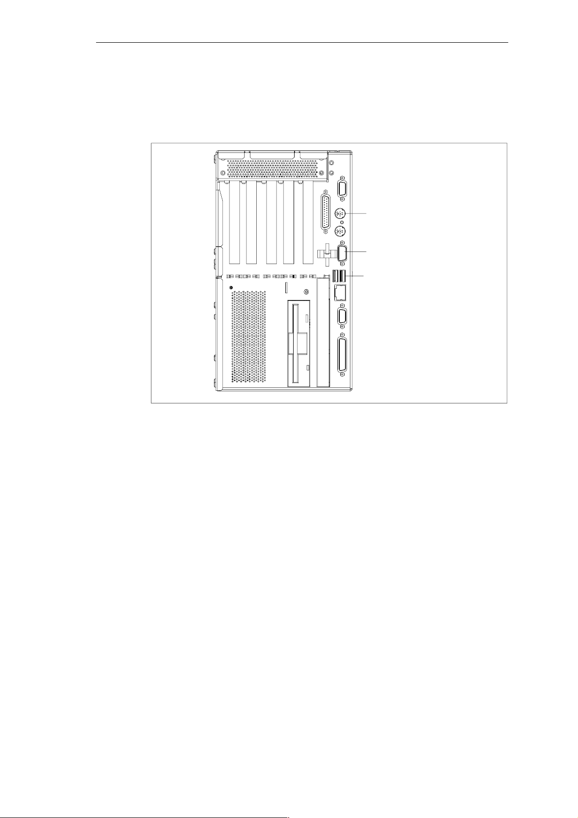
Using a Mouse
You can connect both a PS/2-USB and a serial mouse to the
SIMATI C Box PC 840.
Setting Up and Operating the SIMATIC Box PC 840
SIMATIC Box PC 840 Manual
A5E00085984-04
3-13
Page 46
Setting Up and Operating the SIMATIC Box PC 840
Connecting a PS/2 Mouse
You can connect an external PS/2 mouse or another external pointing device to an
additional PS/2-compatible mouse connector.
Port for PS/2 mouse
(socket)
COM 2 Port
for serial mouse
USB connection for
USB mouse (socket)
Figure 3-9 Connecting the Mouse
To connect the mouse, proceed as follows:
1. Separate the Box PC from the mains.
2. Plug the cable of the PS/2 mouse or another external pointing device into the
mouse connector.
3. Reconnect the Box PC to the mains.
Connecting a Serial Mouse
You can connect a serial mouse to the COM2 serial port. To operate a serial
mouse, the appropriate mouse driver must be initialized and assigned parameters.
You will find the information you need to do this in the description for your mouse
or in the description for the operating system.
1. Separate the Box PC from the mains.
2. Plug the serial mouse into the mouse connector labeled COM2.
3. Secure the connector with the screws.
4. Reconnect the Box PC to the mains.
You can find out how to connect a USB mouse in “Connecting USB devices”.
3-14
SIMATIC Box PC 840 Manual
A5E00085984-04
Page 47
Connecting a PS/2 Keyboard
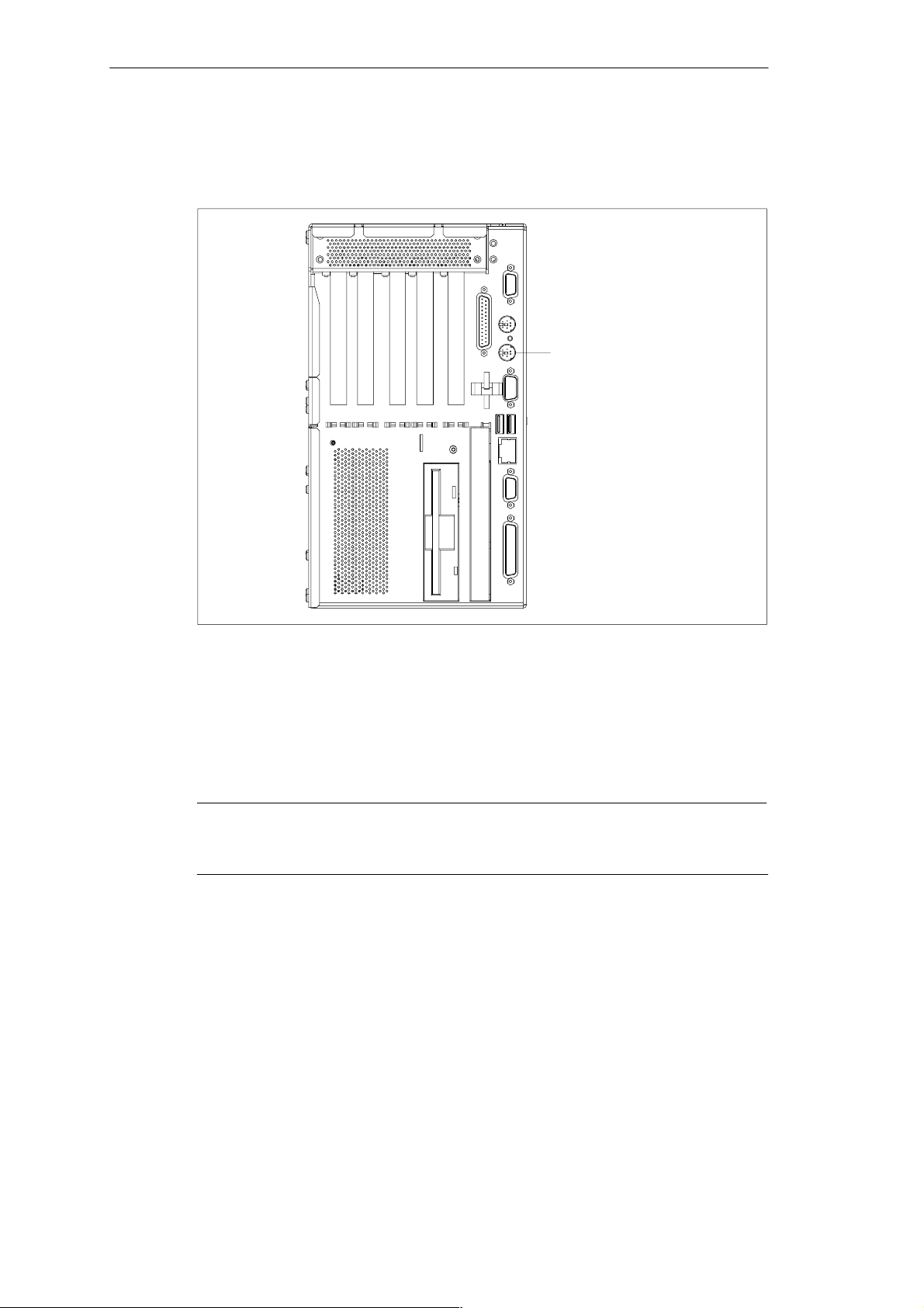
A PS/2 keyboard of your choice can be connected to the SIMATIC Box PC 840.
Setting Up and Operating the SIMATIC Box PC 840
PS/2 keyboard connection
Figure 3-10 Connecting a PS/2 Keyboard
To connect the keyboard, proceed as follows:
1. Separate the Box PC from the mains.
2. Insert the plug of the PS/2 keyboard.
3. Reconnect the Box PC to the mains.
Notice
It is recommended that a keyboard with straight keyboard connector is used, so
that the connector does not obscure adjacent ports.
SIMATIC Box PC 840 Manual
A5E00085984-04
3-15
Page 48
Setting Up and Operating the SIMATIC Box PC 840
Connecting USB Periphery
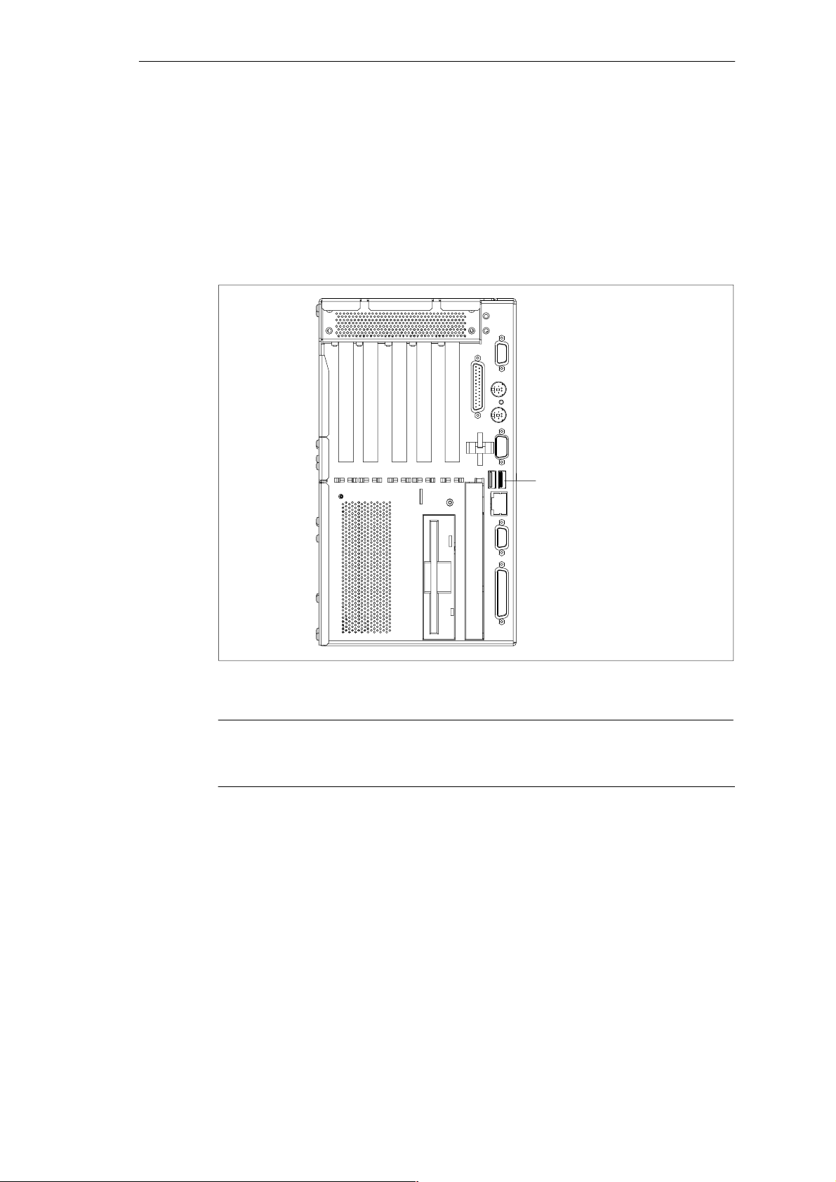
You can connect peripheral devices with USB interfaces to the USB port.
Plug the USB cable into the port.
The device is automatically detected by a Plug and Play operating system, for
example, Windows 98, and is then available.
A USB keyboard can be used to manipulate the BIOS setup.
USB port
Figure 3-11 USB Connection
Notice
Operating systems which do not support Plug and Play (for example, Windows NT
4.0), generally do not allow the operation of USB devices.
3-16
SIMATIC Box PC 840 Manual
A5E00085984-04
Page 49
Setting Up and Operating the SIMATIC Box PC 840
3.5 Connecting the SIMATIC Box PC 840 to Other SIMATIC S5 Devices
Point-to-Point Connection
In this section, you will learn how to connect your SIMATIC Box PC 840 to a
programming device or S5 programmable logic controller using a point-to-point
connection.
You can establish a point-to-point connection by connecting the
SIMATIC Box PC 840 to another programming device or a programmable logic
controller using
A V.24 connection
A TTY connection (Optional product feature)
Connecting the SIMATIC Box PC 840 to an S5 Programmable Logic Controller
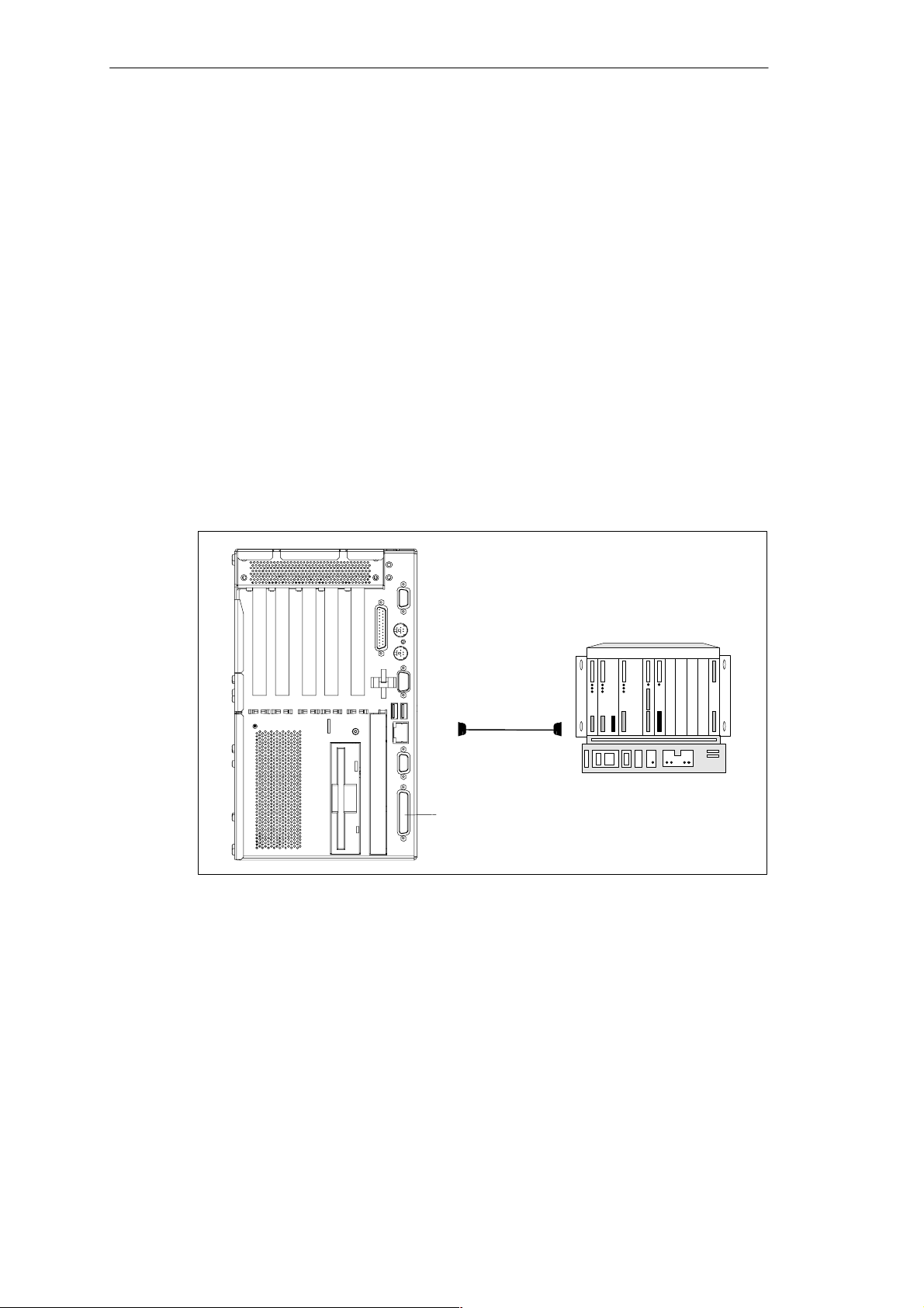
You can connect the SIMA TIC Box PC 8 40 to a SIMATIC S5 programmable logic
controller using the COM1/TTY interface port.
Figure 3-12 Connecting the Box PC 840 to an S5 Programmable Logic Controller
You connect your SIMATIC B o x P C 8 4 0 to a SIMATIC S5 programmable logic
controller as follows:
1. Trennen Sie den Box PC vom Netz
2. Insert the connecting cable into the port COM 1 / AG.
3. Screw down the plug.
4. Plug the cable into the corresponding port on the CPU of the programmable
logic controller.
5. In order to enable TTY operation, you must set TTY to “enabled” in the BIOS
setup.
6. Reconnect the Box PC to the mains.
SIMATIC Box PC 840 Manual
A5E00085984-04
COM 1 (Buchse)
3-17
Page 50

Setting Up and Operating the SIMATIC Box PC 840
(COM 1)
S5 programmable controller
Caution
!
Risk of damage to the SIMATIC Box PC 840!
The interface port may be damaged if you confuse the connections or use the
wrong connecting cables.
Make sure the TTY cable of the SIMATIC Box PC 840 is plugged into the
COM 1 / TTY port and not into the LPT 1 port.
Before inserting the connecting cables, the electrostatic charge in your body, the
device and the connecting cables must be brought to the same potential. Briefly
touch the sheet metal case to do this.
Use only original cables to establish the connection to the programmable
controller.
Connecting the SIMATIC Box PC 840 via an Adapter
The 6ES5 734-2BD20 standatd connecting cable is required for connection to a
pro grammab le con troller . An adapter is available for connecting the
programmable controller using old standard cables.
Tabelle 3-1 Adapter for SIMATIC Box PC 840 Connection
Port
TTY port
SIMATIC Box PC 840 to SIMATIC-
Link Connecting
Cable
Order No:
6ES5 734-2BD20
6ES5 731-1xxx0
15-pin
6ES5 731-0xxx0
25-pin
Adapter
6ES5 731-6AG00
6ES5 731-6AG00
In order to maintain a data transfer rate of 9600 bps up to a distance of 1000 m
(3300 ft), the receiving diode is connected to ground (reference) via the connecting
cable.
Notice
You can obtain lengths differing from the standard connecting cable
(6ES5 734-2BD20) under the order number 6ES5 734-2xxx0, whereby xxx stands
for the length code.
3-18
SIMATIC Box PC 840 Manual
A5E00085984-04
Page 51

Setting Up and Operating the SIMATIC Box PC 840
SIMATIC Box PC 840 to PG Connection (V.24, TTY)
If you want to connect your SIMATIC B ox PC 840 to a programming device, you
can plug the appropriate connecting cable into the V.24 or TTY interface port
Tabelle 3-2 Connection of the SIMATIC Box PC 840 to other PUs
Port Link Connecting Cable
COM 1 as a V.24
port
COM 1 as a TTY
port
with PG 7xx 6ES5 733-5BD20
with PG 6xx Series connection of
6ES5 733 -2xxx0
6ES5 731-6AG00
Order No.:
2)
2)
1)
and
Adapter
6ES5 731-6AG00
Notice
1. When connecting the programming devices in series, make sure you connect
the cable the right way around (see Figure 3-13).
2. The connecting cable can only be ordered as a spare part. The connecting
cable is described in Chapter 7.
3. The line current (TTY) is an optional product feature.
Adapter Connecting cable
Box PC 840
Active Passive
6ES5 731–6AG00 6ES5 733–2xxx0
PG 6XX
Figure 3-13 Direction of Connection: Adapter – Connecting Cable
Notice
For the PC/PG connection, you must switch the TTY ports (COM 1) in the
programmable logic controller to passive by changing the jumper setting. The
SIMATIC Box PC 840 interface is always active!
SIMATIC Box PC 840 Manual
A5E00085984-04
3-19
Page 52
Setting Up and Operating the SIMATIC Box PC 840
3.6 Connecting the SIMATIC Box PC 840 to a SIMATIC S7 Network (PROFIBUS/MPI)
Connecting an S7 Programmable Controller via PROFIBUS/MPI Port
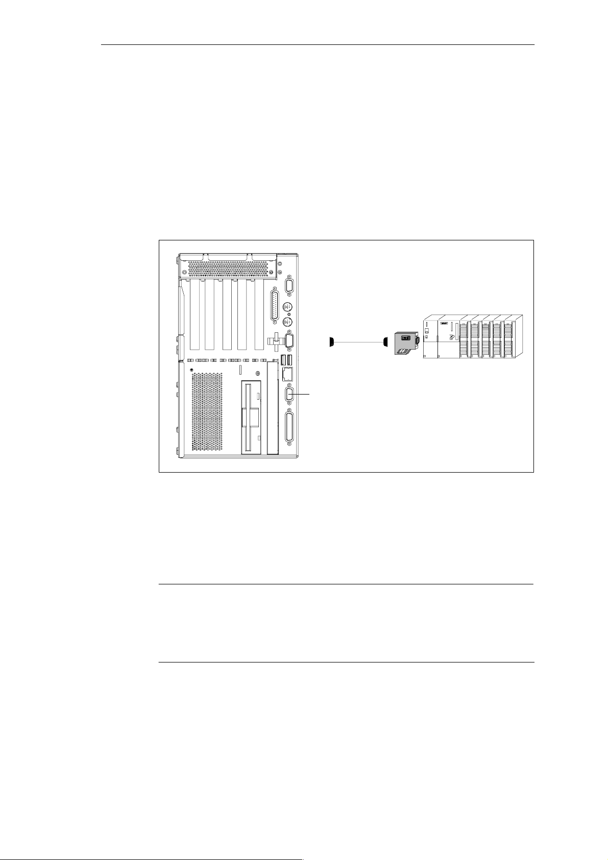
You can connect the SIMATIC Box PC 620 to a SIMATIC S7 automation system
or to a PROFIBUS network via the potentially isolated*) PROFIBUS/M PI port**).
The MPI cable (5m ) f o r connection to SIMATIC S7 CPUs (order no.:
6ES7901-0BF00-0AA 0) is supplied with the SIMATIC Box PC 840.
In disturbed surroundings:
bus connector
6ES7972-0BB10-0XA0
or
6ES7972-0BB20-0XA0
6ES7901-0BF00-0AA0
(5 m length)
PROFIBUS/MPI port
Figure 3-14 Connection Using the PROFIBUS/MPI Port
Proceed as follows when connecting to a SIMATIC S7 programmable logic
controller:
1. Separate the Box PC from the mains.
2. Connect the cable to the PROFIBUS/MPI port.
Caution
Risk of damage to the SIMAT IC Box PC 840!
Before plugging in the connecting cables, the static charge on your body, the unit,
and the cables must be equalized. You can do this by briefly touching the metal
housing.
* Electrical isolation in the saftey extra-low voltage circuit (SELV cir cuit).
** Optional product feature
3-20
SIMATIC Box PC 840 Manual
A5E00085984-04
Page 53

Connecting
Via the PROFIBUS/MPI port, you can connect your PC to
MPI networks (S7-200, S7-300, and S7-400) or
PROFIBUS DP networks (DP components).
MPI/PROFIBUS-DP Network
Up to 32 devices (PC, programming device, or programmable controller) can be
connected to the PROFIBUS/MPI interface to form a network segment. The physical connection to the network is via a floating RS485 interface which is a component of the PC basic module.
Several network segments can be connected via repeaters. The complete network
can comprise up to 127 stations. Data transmission rates from 9.6 Kbps to
12 Mbps are possible.
Setting Up and Operating the SIMATIC Box PC 840
SIMATIC Box PC 840 Manual
A5E00085984-04
3-21
Page 54

Setting Up and Operating the SIMATIC Box PC 840
3.7 Networking the SIMATIC Box PC 840 with Other Stations on PROFIBUS
Networking the SIMATIC Box PC 840 on PROFIBUS
PROFIBUS is an open and robust bus system for industrial use. It can be used to
configure networks with up to 32 stations per segment. PROFIBUS DP suppor t s
data transfer rates from 9.6 Kbps to 12 Mbps.
How the Network Functions
The network operates on the master-slave principle with token passing (complying
with DIN19245, PROFIBUS). It distinguishes between active and passive stations.
An active station receives the token and passes it on to the next station within a
specified time.
Hardware Requirements
Using the following components, for example, you can connect or network the
SIM A T I C Bo x PC 840 with PROFIBUS:
RS 485 MPI/DP port adapter (not available for the basic variant of the Box PC)
Shielded, twisted pair (bus cable or connecting cable to network).
3-22
SIMATIC Box PC 840 Manual
A5E00085984-04
Page 55

Setting Up and Operating the SIMATIC Box PC 840
3.8 Ethernet (RJ45 Ethernet Port)
Networking the Box PC 840 via the RJ45 Ethernet Port
The RJ45 Ethernet port is a Twisted Pair (TP) port with a data transfer rate of
10/100 Mbps. The onboard port is compatible with the Intel pro/100+ PCI adapter.
The port is Plug and Play capable and is automatically recognized in Windows.
The log settings are carried out in the Windows control panel.
Notice
A class 5 Ethernet cable is required to operate ther 100 Mbps.
3.9 Connection under Windows
Windows supports point-to-point connections via the LPT or COM port. The
required connecting cables are standard, commercially available products. More
information is available in the Networks section of the Windows description and in
the online Help system under “Connection to Another Computer”.
SIMATIC Box PC 840 Manual
A5E00085984-04
3-23
Page 56

Setting Up and Operating the SIMATIC Box PC 840
3-24
SIMATIC Box PC 840 Manual
A5E00085984-04
Page 57

SIMATIC Box PC 840 Expansions
What Does This Chapter Contain?
You can enhance the performance of your SIMATIC Box PC 840 by adding an
additional main memory, drives and expansion modules. This chapter describes
how to expand your SIMATIC Box PC 840. Please observe the relevant safety
guidelines.
Chapter Overview
Section Description Page
4.1 Opening the Unit 4-2
4.2 Installing Memory Expansion Submodules 4-4
4.3 Replacing the Backup Battery 4-9
4.4 Installation of Expansion Cards 4-11
4.5 Removal and Installation of Drives 4-15
4.6 Removal and Installation of the Power Supply Unit 4-20
4.7 Removal and Installation of the Bus Board 4-21
4.8 Removal and Installation of the Motherboard 4-22
4.9 Removal and Installation of the Device Fan 4-23
4.10 Processor Change 4-24
4.11 Reset Button 4-25
4
SIMATIC Box PC 840 Manual
A5E00085984-04
4-1
Page 58

SIMATIC Box PC 840 Expansions
4.1 Opening the Unit
4.1.1 Prerequisites
The device is designed for easy maintenance so that any work that is necessary
can be done quickly and at low cost.
Caution
The electronic components on the printed circuit boards are extremely sensitive to
electrostatic discharge. Certain precautionary measures are therefore necessary
when handling such components. These measures are explained in the guidelines
for handling electrostatically sensitive devices (ESD) in Appendix A.
Limitation of Liability
All technical specifications and licences apply only to expansion functions
approved by SIEMENS.
No liability can be accepted for impairment of functions caused by the use of
devices and components of other manufacturers.
All the modules and components in the SIMATIC Box PC 840 are electrostatically
sensitive. Please read the ESD guidelines at the end of this book carefully. The
following symbol warns that electrostatically-sensitive modules are present.
Before Opening the Unit
Note the following rules before opening the unit:
Before you disconnect the power supply cable, discharge any electrostatic
charge on your body. You can do this by touching the metal mounting plate for
the interfaces on the left-hand side panel of the unit.
Discharge any electrostatic charge from tools that you are using.
Wear a grounding wrist-strap if you are handling components.
Leave components and modules in their packing until you are ready to install
them.
4-2
Disconnect the SIMATIC Box PC 840 from its power supply and remove the
battery before plugging in or removing any modules or components.
Touch components and modules only on their edges. Above all, do not touch
the connecting pins and printed conductors.
Never operate the SIMATIC Box PC 840 with the cover open.
SIMATIC Box PC 840 Manual
A5E00085984-04
Page 59
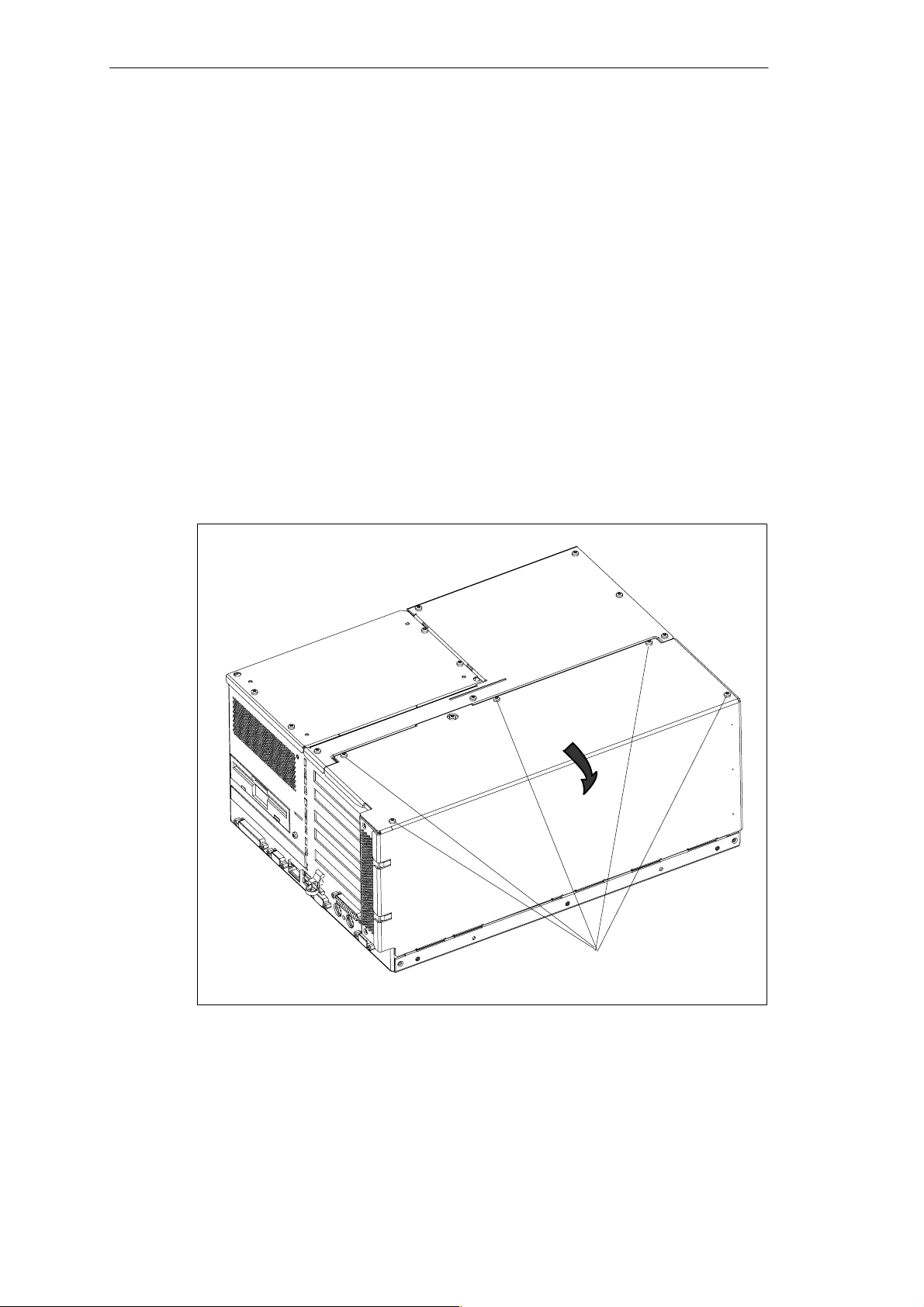
Tools
You can carry out all necessary installation work on the SIMATIC box PC 840 with
screwdrivers of the TORX T10 and TORX T8 types.
4.1.2 Opening the SIMATIC BOX PC 840
To open the SIMATIC Box PC 840, proceed as follows:
1. Pull out the power supply connector and remove all connecting cables from the
unit, including the keyboard cable.
2. Remove the PC from its mounting/cabinet (only necessary if screws which have
to be removed are inaccessible in the fitted position).
3. Undo the five screws (see Fig. 4-1) on the housing cover.
4. Tilt the cover foreward.
5. Then you can remove the housing cover.
SIMATIC Box PC 840 Expansions
Figure 4-1 SIMATIC Box PC 840 Prepared for Opening
SIMATIC Box PC 840 Manual
A5E00085984-04
Screws on the housing cover (M3)
4-3
Page 60
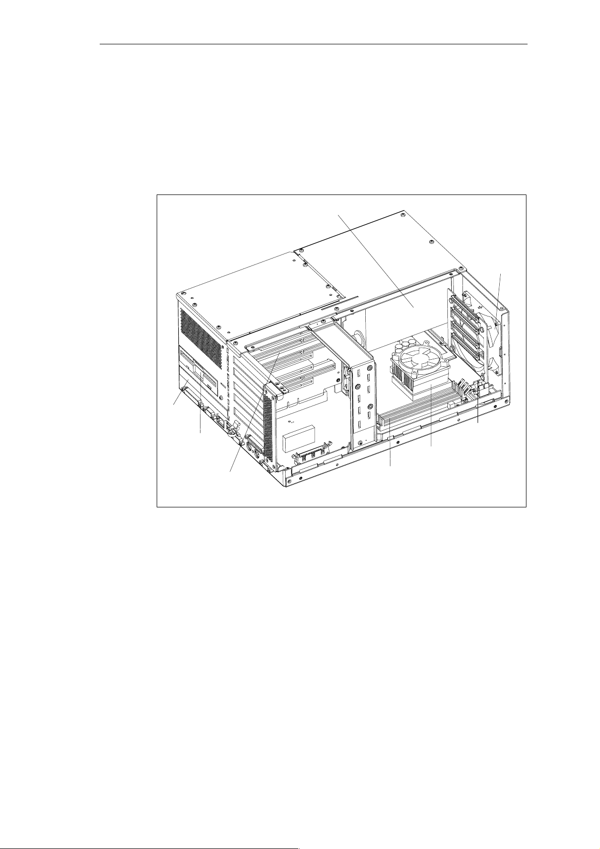
SIMATIC Box PC 840 Expansions
4.1.3 Components Visible after Opening the Unit
Components
Once you have removed the housing cover of your unit, the components are
visible.
Power supply unit
Fan
CD ROM
Floppy drive
or LS 240
Bus board
Figure 4-2 SIMATIC Box PC 840 Open
Backup
battery
Processor
Memory extension
4-4
SIMATIC Box PC 840 Manual
A5E00085984-04
Page 61
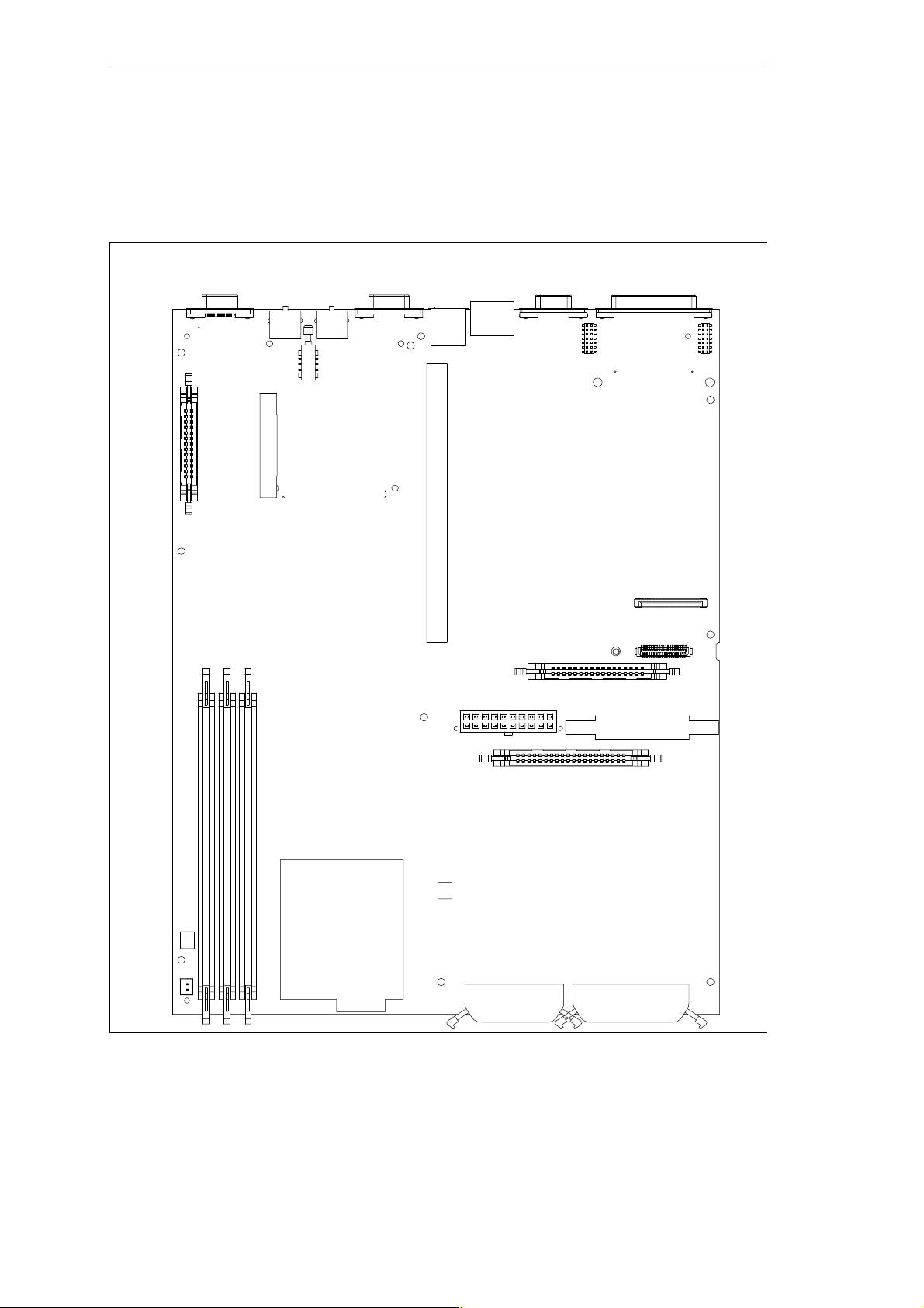
4.1.4 The Motherboard
The motherboard is the heart of the SIMATIC Box PC 840. Here, data is
processed and stored, and interfaces and device I/Os are controlled and managed.
SIMATIC Box PC 840 Expansions
X303
X34
X3X4X5
X22S1X23
X33
X31
X36
X50
X20
X700
X26
X400
X28
X30
X29
X25
X12
X10
X42
X49
Figure 4-3 Motherboard
X1
X41
X7
X300
X44
SIMATIC Box PC 840 Manual
A5E00085984-04
4-5
Page 62

SIMATIC Box PC 840 Expansions
Components on the Motherboard
The following components are located on the motherboard of the
SIMATIC Box PC 840:
Slot Interface/Port
X1 Processor socket with heat sink
X3, X4, X5 DIMM slots for memory expansion
X7 2.54 mm primary IDE (HDD)
X10 2 mm secondary IDE
X12 Plug for FPC secondary IDE (Slim LS240/CD ROM or Slim LS240/CD RW/
X20 Socket connector for bus board
X22 PS/2 mouse connection
X23 PS/2 keyboard connection
X25 Connection for Slim line 1.44 MB floppy
X26 Connection for standard floppy
X28 Internal socket connector for COM1 (V.24/TTY) module
X29 Internal male connector for COM1 (V.24/TTY) module
X30 Serial port COM 1/TTY
X31 Serial port COM 2
X33 COM2 internal for Touch Screen
X34 Parallel port LPT 1
X36 USB port
X40, X42 Device fan connector
X41 Processor fan
X44 I/O interface for front port connection
X49 Connection for backup battery
X50 Connection to power supply (power supply unit)
X300 LVDS display port
X303 VGA monitor connector
X400 MPI/DP port 12
X700 Ethernet
S1 Button for hardware reset
DVD)
4-6
SIMATIC Box PC 840 Manual
A5E00085984-04
Page 63
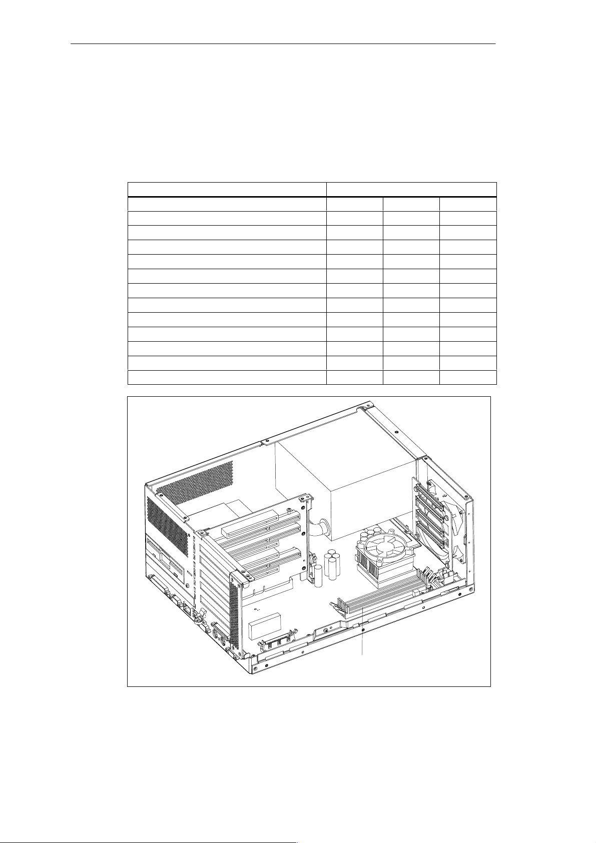
SIMATIC Box PC 840 Expansions
4.2 Installing Memory Expansion Submodules
The motherboard has 3 slots for 144 pin SDRAM memory submodules. This allows
you to expand the memory capacity of your SIMATIC Box PC 840 to a maximum
of 512 Mbytes.
Either one, two or three modules can be installed.
Memory Modules
64 Mbytes 128 Mbytes 256 Mbytes
64 Mbytes 1 – –
128 Mbytes 2 – –
128 Mbytes – 1 –
192 Mbytes 1 1 –
192 Mbytes 3 – –
256 Mbytes 2 1 –
256 Mbytes – 2 –
256 Mbytes – – 1
384 Mbytes – 1 1
384 Mbytes 2 – 1
512 Mbytes – – 2
512 Mbytes – 2 1
Figure 4-4 Position of the SDRAM Memory Modules
SIMATIC Box PC 840 Manual
A5E00085984-04
Memory expansion
4-7
Page 64

SIMATIC Box PC 840 Expansions
Caution
The electronic components of the printed circuit boards are extremely sensitive to
electrostatic discharge. Certain precautionary measures are therefore necessary
when handling such components. These measures are explained in the guidelines
for handling electrostatically sensitive devices (ESD) in Appendix A.
Installing the SDRAM Cards
To plug in expansion submodules, proceed as follows:
1. Open the unit as described in Section 4.1.
2. Plug the cards into the slots. Note the safety recess on the connector side of
the SDRAM card.
3. Push the card down applying light pressure until it locks into place.
4. Close the unit.
Installation
Caution
Make sure that the cards sit securely in the slots, otherwise they can fall out and
be damaged.
The memory configuration is detected automatically. When you switch on the unit,
the distribution of base and extended memory is displayed on the screen.
4-8
SIMATIC Box PC 840 Manual
A5E00085984-04
Page 65

SIMATIC Box PC 840 Expansions
4.3 Replacing the Backup Battery
Battery Power Supply for Real-Time Clock and Configuration
A backup battery (3.6 V-lithium battery) powers the the real-time clock even after
the SIMATIC Box PC 840 is switched off. In addition to the time of day, all the
information about the SIMATIC Box PC 840 (device configuration) is stored in
RAM. If the backup battery fails or is removed, all these data are lost.
The clock uses very little power and the lithium battery has a high capacity so that
the battery can provide backup power for the real-time clock for many years and
seldom needs to be replaced.
Battery Voltage too Low
If the battery voltage is too low, the time is lost, and a correct device configuration
can no longer be guaranteed.
In this case, you must replace the backup battery. The battery is in a battery holder
below the device fan.
Replacing the Battery
To change the battery, proceed as follows:
1. Remove the power cable and all the connecting cables.
2. Open the unit as described in Section 4.1.
3. Change the backup battery inserted in the motherboard by pulling out the
connector and removing the battery from the battery holder.
4. Secure the new battery in its holder.
5. Insert the battery connector in the motherboard.
6. Close the unit.
SIMATIC Box PC 840 Manual
A5E00085984-04
4-9
Page 66
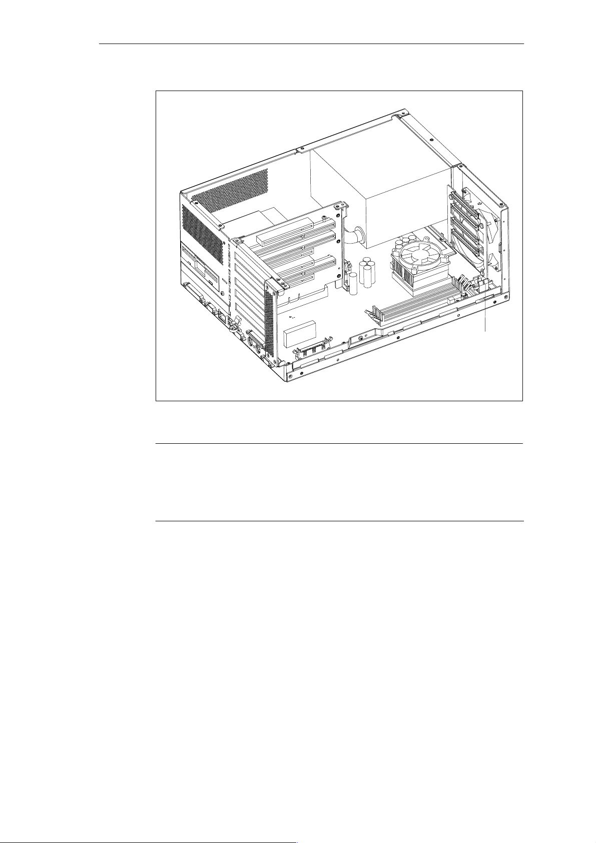
SIMATIC Box PC 840 Expansions
Figure 4-5 Position of the Backup Battery
Caution
Risk of damage!
Only replace the lithium battery with an identical battery or with a type
recommended by the manufacturer (Order No.: W79084-E1003-B1).
Dispose of used batteries in keeping with local regulations.
Changing SETUP
If you change the battery or unplug the battery connector you must run the
BIOS-SETUP program to reset your programming device configuration data (see
Chapter 5).
Backup Battery
4-10
SIMATIC Box PC 840 Manual
A5E00085984-04
Page 67
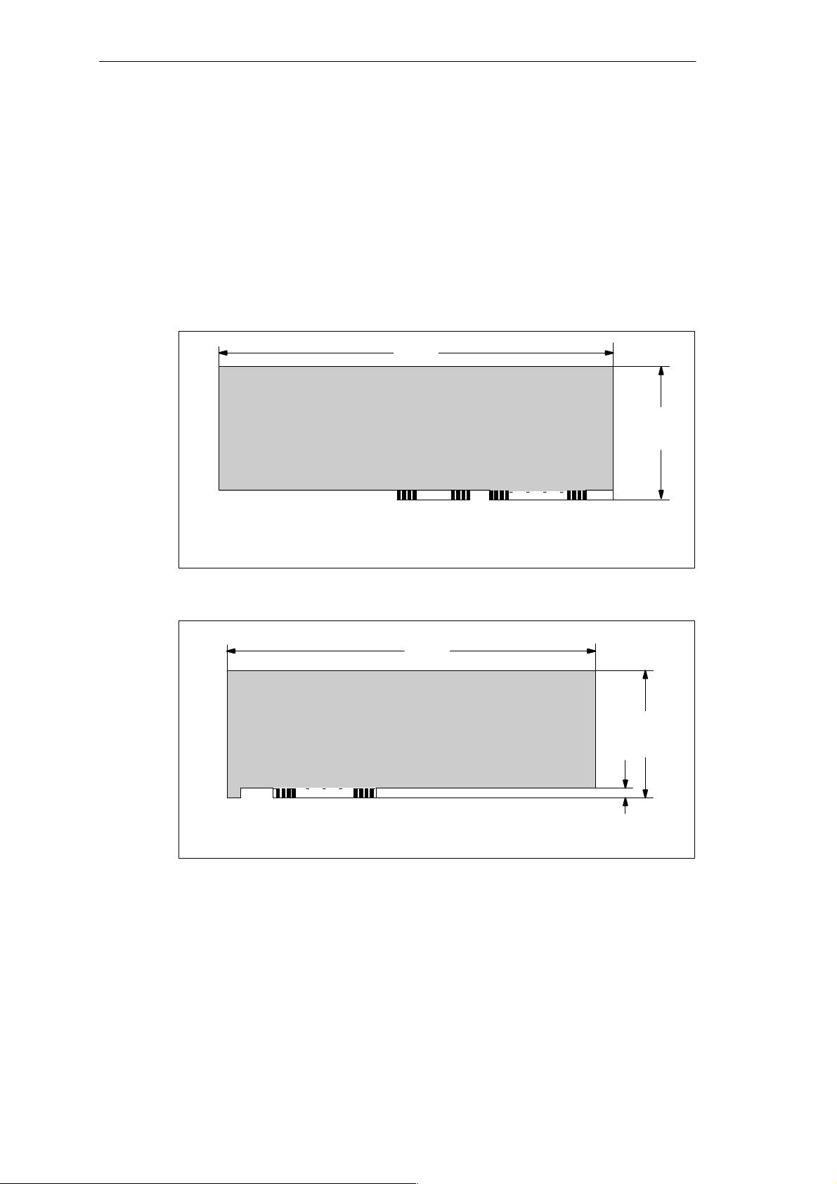
4.4 Installation of Expansion Cards
Notes about the Cards
The SIMATIC Box PC 840 is designed for the use with cards as per the AT/
PCI specification. The dimensions of the cards may not exceed the stated
dimensions. If the height is exceeded, contact problems, malfunctions and
difficulties with the assembly cannot be excluded. The illustrations show cards with
a full AT/PCI overall length. Depending on the slot, there may be restrictions on the
overall length.
340,7
(13.41)
SIMATIC Box PC 840 Expansions
(4.8)
121,92
All measurments in mm
All measurments ( ) in inch
Figure 4-6AT Card
All measurments in mm
All measurments ( ) in inch
Figure 4-7Long PCI Cards (5 V)
C18 C1
312
(12.28)
A31 A1
8,19
(4.2)
106,68
(0.32)
Note about Long PCI Cards
Before long PCI cards can be inserted into the guides of the fan trough, they must
be fitted with a so-called extender (this should form part of the scope of supply of
long PCI boards). Long PCI cards can be inserted into the guides of ISA modules
by means of this extender.
SIMATIC Box PC 840 Manual
A5E00085984-04
4-11
Page 68
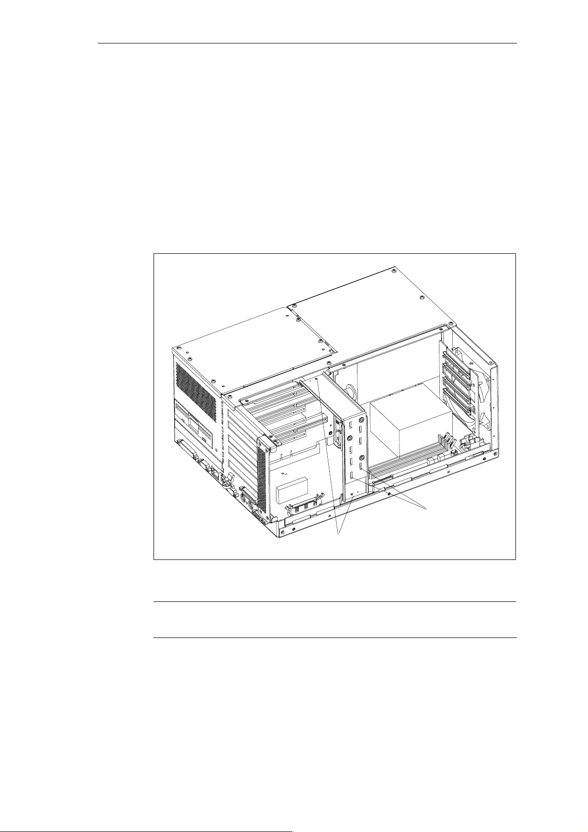
SIMATIC Box PC 840 Expansions
4.4.1 Removal and Installation of the Device for Holding Down the Modules
The device for holding down the modules is attached to the housing with two
screws. It has five slits, through which the slide elements are inserted.
Proceed as follows:
1. Open the housing as described in Section 4.1.
2. Undo both fixing screws of the device for holding down the modules.
3. During assembly, ensure that the device for holding down the modules is
resting on the guide on the housing.
4-12
Guide slits for slide elements
Fixing screw for device for
holding down the modules
Figure 4-8 Removal/Installation of the Device for Holding Down the Modules
Note
The slide elements are in the enclosed plastic bag.
SIMATIC Box PC 840 Manual
A5E00085984-04
Page 69

Aligning the Holding-Down Device
Proceed as follows to install the holding-down device.
1. Insert the slide element through the guide slit until it is resting firmly on the
module. The module must now be introduced into the notch.
Caution
No pressure may be exerted on the module! Therefore, do not use force to press
the slide element onto the module.
2. Cut off the projecting part of the slide element:
– Score the slide element at the top edge of the holding-down device with a
knife and break it off.
– Nip off the surplus with a sharp side cutter.
SIMATIC Box PC 840 Expansions
SIMATIC Box PC 840 Manual
A5E00085984-04
4-13
Page 70
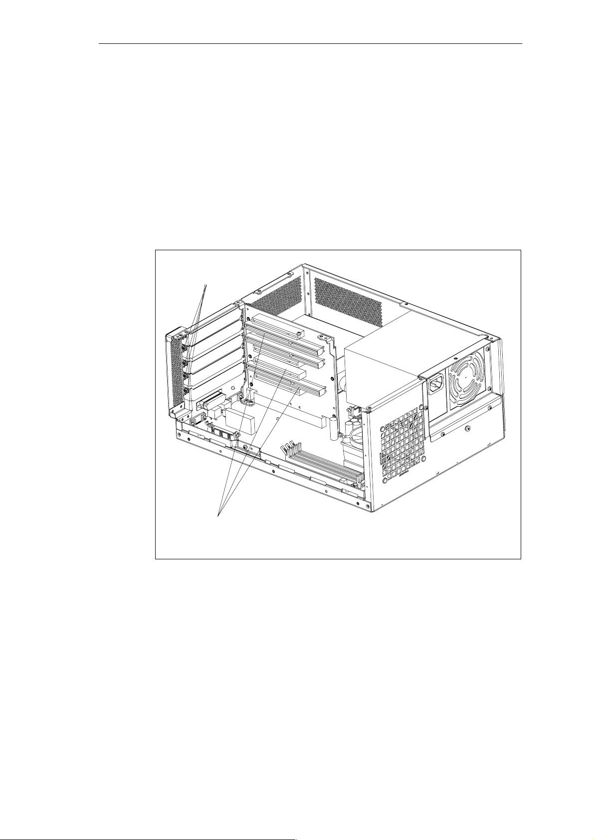
SIMATIC Box PC 840 Expansions
4.4.2 Removal and Installation of an Expansion Module
Proceed as follows:
1. Open the housing as described in Section 4.1.
2. Remove all connectors from the expansion module and note the assignment.
3. Remove the device for holding down the modules as described in Section 4.4.1.
4. Undo the screws on the slot plate of the module.
5. Pull the module out of the slot.
6. Proceed in the reverse order to install the new expansion module.
Screws at
slot plate
4-14
Slots for expansion modules
Figure 4-9 Removal/Installation of an Expansion Module
SIMATIC Box PC 840 Manual
A5E00085984-04
Page 71
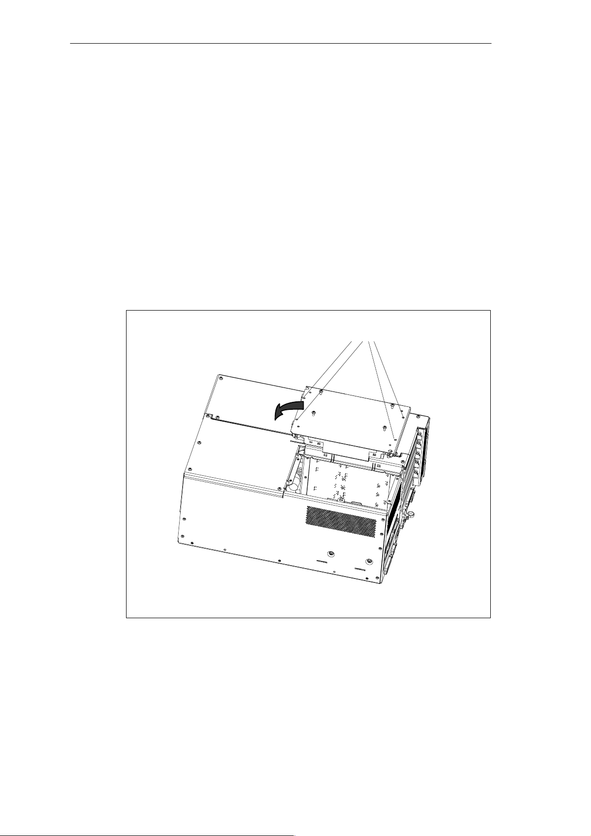
SIMATIC Box PC 840 Expansions
4.5 Removal and Installation of Drives
4.5.1 Removal and Installation of the Hard Disk Drive
1. Undo the 4 screws of the drive holder.
2. Open the drive holder.
3. Detach the drive holder from the mounting and lay the drive holder with its top
on the housing.
4. Note the cable assignment and pull off the cables.
5. Undo the four screws which secure the hard disk drive to the vibration-damped
part of the mounting. Remove the hard disk drive from the mounting.
6. Proceed in the reverse order to fit the new drive. The new drive must be of the
same type as the one removed.
Fixing screws
Figure 4-10 Installation and Removal of the Drive Holder
SIMATIC Box PC 840 Manual
A5E00085984-04
4-15
Page 72

SIMATIC Box PC 840 Expansions
Figure 4-11 Hard Disk Drive with Holder Removed
4-16
SIMATIC Box PC 840 Manual
A5E00085984-04
Page 73
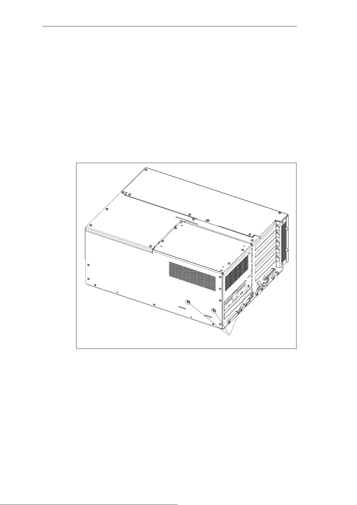
SIMATIC Box PC 840 Expansions
4.5.2 Removal and Installation of the Floppy/LS240 or CD ROM, CD RW/DVD Drive Holder
1. Open the housing as described in Section 4.1.
2. Remove the hard disk drive holder as described in Section 4.5.1.
3. Undo the data cable of the floppy/LS240 drive and the power supply cable.
4. Release the interlocking screw of the CD ROM flex-lead on the motherboard
and pull the flex-lead out of the connector assembly.
5. Undo the three screws on the drive holder and lift this holder upwards out of the
housing.
6. Proceed in the reverse order to fit the drive holder.
Figure 4-12 Installation of the Drive Holder
SIMATIC Box PC 840 Manual
A5E00085984-04
Fixing screws of the drive holder
4-17
Page 74
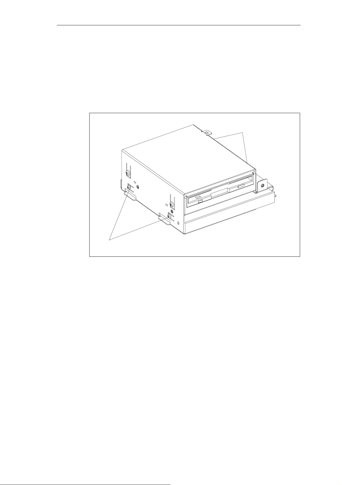
SIMATIC Box PC 840 Expansions
4.5.3 Removal and Installation of the Floppy/LS 240 Drive
1. Remove the drive holder as described in Section 4.5.2.
2. Undo the four screws of the drive.
3. Lift the drive upwards out of the drive holder.
4. Proceed in the reverse order to fit the new drive.
Fixing screws of the drive
Fixing screws of the drive
Figure 4-13 Installation of the Floppy/LS 240 Drive
4-18
SIMATIC Box PC 840 Manual
A5E00085984-04
Page 75
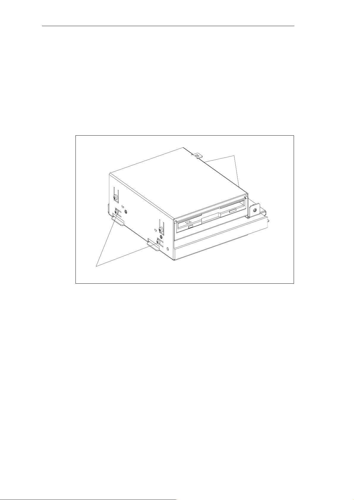
SIMATIC Box PC 840 Expansions
4.5.4 Removal and Installation of the CD ROM or CD RW/DVD Drive
The removal and installation of the CD drive takes place with the same steps as for
the floppy drive.
1. Remove the drive holder as described in Section 4.5.2.
2. Undo the four screws of the drive.
3. Lift the drive upwards out of the drive holder.
4. Proceed in the reverse order to fit the new drive.
Fixing screws of the drive
Fixing screws of the drive
Figure 4-14 Installation of the CD ROM, CD RW/DVD Drive
SIMATIC Box PC 840 Manual
A5E00085984-04
4-19
Page 76
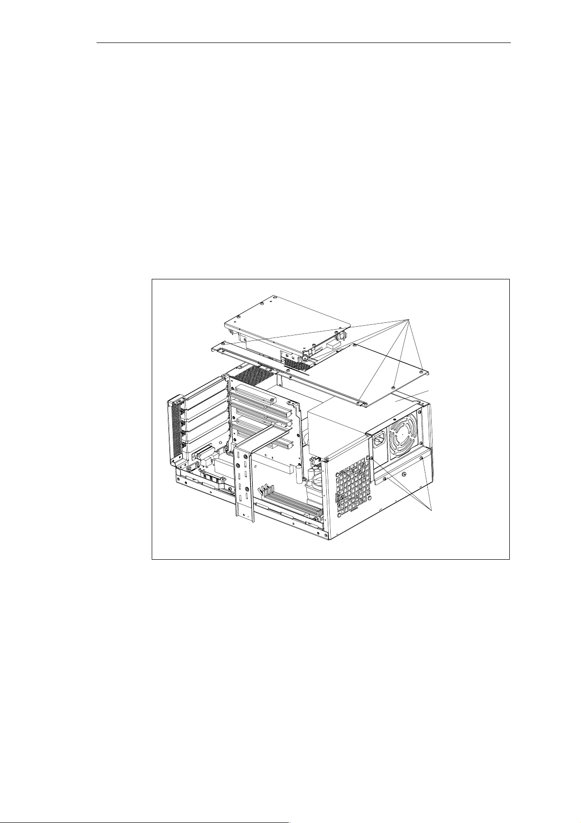
SIMATIC Box PC 840 Expansions
4.6 Removal and Installation of the Power Supply Unit
1. Open the system housing as described in Section 4.1.
2. Remove the drive holder as described in Section 4.5.1.
3. Note the cable assignment and remove them from the motherboard and the
drives.
4. Undo and remove the six screws of the cover of the power supply unit from the
housing.
5. Undo the three fixing screws (TORX T10) on the mounting plate of the power
supply unit.
6. From the side, pull out the power supply unit from the housing.
7. Proceed in the reverse order to fit the new power supply unit.
Screws of
power supply unit cover
Figure 4-15 Removal and Installation of the Power Supply Unit
Power supply unit
Screws on
mounting plate
4-20
SIMATIC Box PC 840 Manual
A5E00085984-04
Page 77
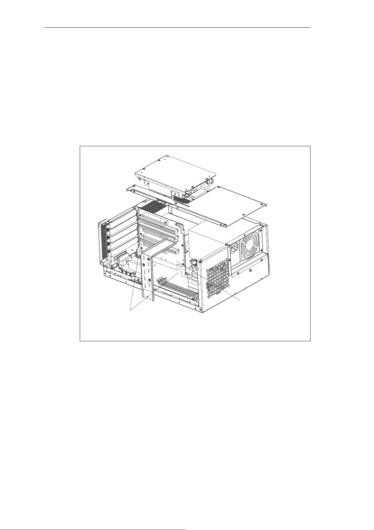
SIMATIC Box PC 840 Expansions
4.7 Removal and Installation of the Bus Board
1. Open the housing as described in Section 4.1.
2. Remove all the modules from the slots (proceed as described in Section 4.4.2.).
3. Remove the drive holder as described in Section 4.5.1.
4. Undo the two screws on the motherboard.
5. Pull the bus board off the motherboard.
6. Proceed in the reverse order to refit the bus board.
Fixing screw of the bus board
Figure 4-16 Removal and Installation of the Bus Board
Bus board
SIMATIC Box PC 840 Manual
A5E00085984-04
4-21
Page 78
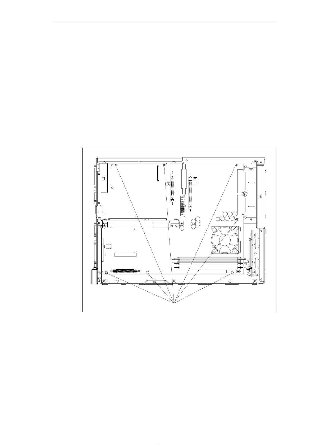
SIMATIC Box PC 840 Expansions
4.8 Removal and Installation of the Motherboard
1. Open the housing as described in Section 4.1.
2. Remove all the modules from the slots (proceed as described in Section 4.4.2).
3. Remove the drive holder as described in Section 4.5.1.
4. Remove the power supply unit as described in Section 4.6.
5. Undo the cables for the device fan, the battery and the parallel port.
6. Undo the 7 screws on the motherboard and the 10 hexagon head screws on the
ports.
7. Remove the bus board and the motherboard.
8. Proceed in the reverse order to refit the motherboard.
4-22
Fixing screws on the motherboard
Figure 4-17 Fixing Screws on the Motherboard
The motherboard is available as a spare part without processor, memory modules
and bus board.
SIMATIC Box PC 840 Manual
A5E00085984-04
Page 79
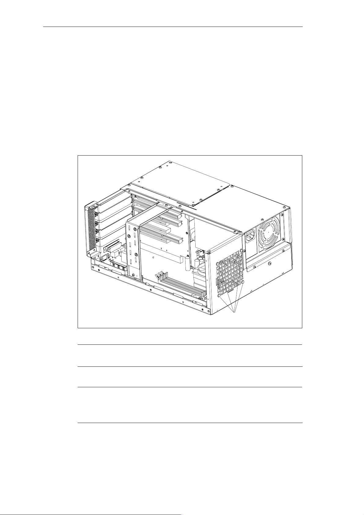
SIMATIC Box PC 840 Expansions
4.9 Removal and Installation of the Device Fan
The SIMATIC Box PC 840 is cooled by means of a fan which draws hot air out of
the housing.
1. Open the housing as described in Section 4.1.
2. Pull off the fan cable connector on the motherboard.
3. The fan is secured to the housing by four plastic rivets. Undo the rivets by
pressing out the gudgeon from the rear of the rivet shank.
4. Remove the fan.
5. Undo the four plastic rivets on the plate with the guide rails.
6. Proceed in the reverse order for assembly.
Figure 4-18 Removal and Installation of the Fan
Notice
Only a fan of the same type may be fitted!
Caution
To ensure that the device is adequately cooled, take care that the running direction
of the fan is correct when installing.
Ensure that the arrow on the fan points to the housing wall.
SIMATIC Box PC 840 Manual
A5E00085984-04
Plastic rivets
4-23
Page 80
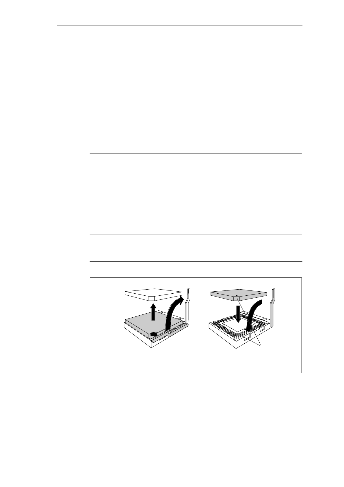
SIMATIC Box PC 840 Expansions
4.10 Processor Change
Proceed as follows to exchange the processor:
1. Pull out the fan cable plug.
2. Remove the cooling unit which is fixed using a lifting lever.
3. Then push the lever in the direction of the arrows (1) and swing it upwards as
far as it will go (2).
4. Lift the old processor out of the slot (3).
5. Put the new processor in its socket and make sure that the marks on top of the
processor have the exact position (4) as indicated on the slot (A).
Caution
The marks on top of the processor may be covered by the cooling unit. In this
case, use the marks between the pin rows on the outside of the processor.
6. Swing the lever downwards until it clicks into position (5).
7. Fix the cooling unit using the lifting lever.
8. Reattach the fan cable plug to the motherboard.
Caution
Operating a processor at a higher frequency than the maximum permissible
frequency may result in destruction of the processor, data loss, or data corruption.
2
3
1
4
5
A
4-24
Figure 4-19 Changing the Processor
SIMATIC Box PC 840 Manual
A5E00085984-04
Page 81
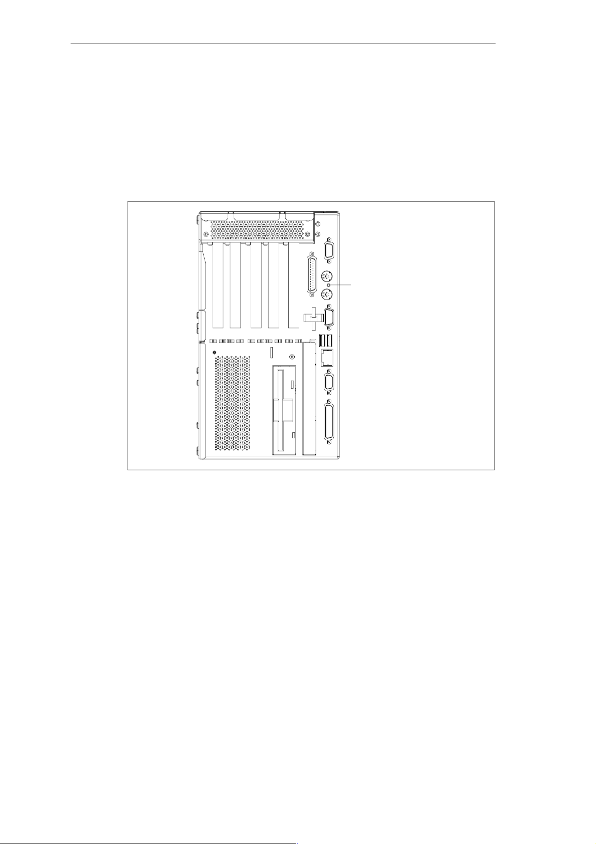
4.11 Reset Button
A hardware reset is initiated by means of the reset button on your device. The PC
is restarted.
The SIMATIC Box PC 840 reset button is located between the two PS/2 sockets
on the port side. The reset button can be only actuated with a thin pen (for
example, an opened-up paper clip).
SIMATIC Box PC 840 Expansions
Reset button
Figure 4-20 Reset Button on the SIMATIC Box PC 840
SIMATIC Box PC 840 Manual
A5E00085984-04
4-25
Page 82

SIMATIC Box PC 840 Expansions
4-26
SIMATIC Box PC 840 Manual
A5E00085984-04
Page 83

Configuring the S IM ATIC Box PC 840
What Does This Chapter Contain?
In this chapter, you will learn how to configure your programming device. You need
to do this if you change your system by adding, removing, or exchanging
expansion modules and memory expansions, or by replacing a system module.
Chapter Overview
Section Description Page
5.1 Changing the Device Configuration with BIOS SETUP 5-2
5.2 The Main Menu 5-5
5.3 The Advanced Menu 5-12
5.4 The Security Menu 5-18
5.5 The Power Menu 5-20
5.6 The Boot Sequence Menu 5-21
5.7 The Version Menu 5-23
5.8 The Exit Menu 5-24
5.9 Default Setup Settings 5-25
5
SIMATIC Box PC 840 Manual
A5E00085984-04
5-1
Page 84

Configuring the SIMATIC Box PC 840
5.1 Changing the Device Configuration with BIOS SETUP
Changing the Device Configuration
Your SIMATIC Box PC 840 device configuration is set for working with the software
supplied with the unit. You should only change the preset values if you have
modified your Box PC in any way or if a fault occurs when the unit is powered up.
BIOS SETUP Program
The BIOS SETUP program is in the ROM-BIOS. Information about the system
configuration is stored in the battery-backed RAM of the SIMATIC Box PC 840.
You can use SETUP to set the hardware configuration (for example, hard disk
type) and define the system characteristics. You can also use SETUP to set the
time of day and date.
Incorrect BIOS Data
If incorrect BIOS data are detected when you boot the system, the BIOS prompts
you to
Start BIOS SETUP by pressing F2 or
Continue booting by pressing F1.
Starting BIOS SETUP
On completion of the startup test, the BIOS gives you the opportunity of starting
the SETUP program by displaying the following screen prompt:
PRESS < F2 > to enter SETUP
To start SETUP, proceed as follows:
1. Reset your SIMATIC Box PC 840 (warm or cold restart).
2. Press the F2 key as long as the BIOS prompt appears on the screen.
BIOS SETUP Menus
The various menus and submenus are listed on the following pages. You can get
all the information you need for the SETUP entry selected from the
“Item Specific Help” part of the relevant menu.
5-2
SIMATIC Box PC 840 Manual
A5E00085984-04
Page 85
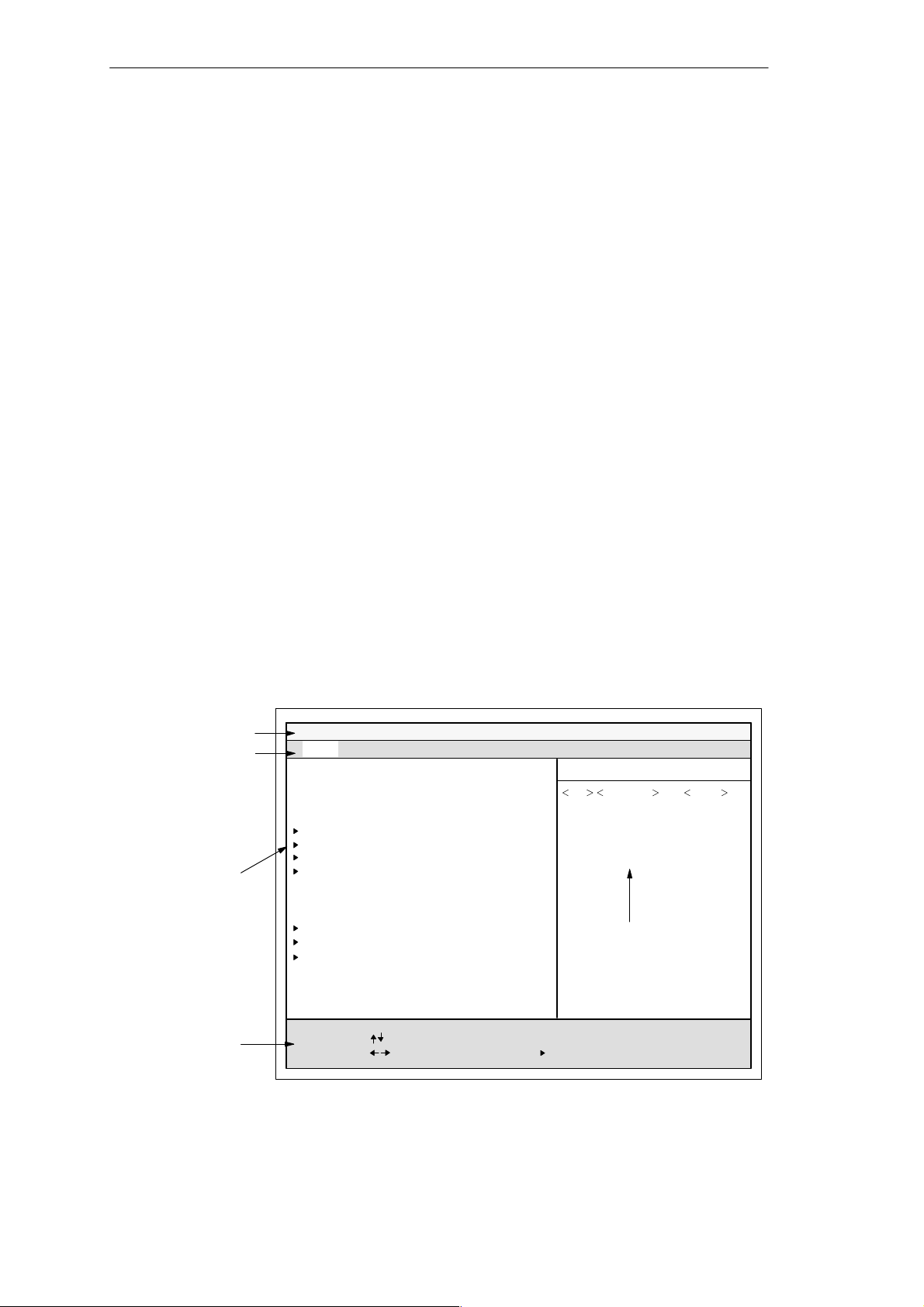
Screen Display Following Power On
With the default setting of your PC, the display shown below appears following
power-on:
Phoenix BIOS 4.0 A5E000xxxxx–ES0x
Copyright 1985-2000 Phoenix Technologies Ltd.
All Rights Reserved.
SIMATIC Box PC 840 V10.01.02
CPU = Intel PentiumIII 866BMHz
640K System RAM Passed
127MB Extended RAM Passed
0256K Cache SRAM Passed
System BIOS shadowed
Video BIOS shadowed
Mouse initialized
Fixed Disk 0: xxxx
ATAPI CD-ROM: Txxx
Press <F2> to enter SETUP
Configuring the SIMATIC Box PC 840
If you press the F2 key while the above display is shown, you select the
ROM-based BIOS setup program. In this program, you can set a number of
system functions and hardware configurations of your programming device.
The default settings are effective on delivery. You can change these settings using
the BIOS setup. The modified settings become effective when you have
saved them and terminated the BIOS setup.
The following screen shots may differ from what is shown here, depending on the
device configuration. The following screen form appears when you start the BIOS
setup:
Header
Menu bar
Selectable
submenu
Main Security Power Exit
System Time:
System Date:
Diskette A:
Primary Master
Primary Slave
Secondary Master
Secondary Slave
Memory Cache [WriteBack]
Boot Options
Keyboard Features
Hardware Options
Advanced
PhoenixBIOS Setup Utility
[ 15:35:32 ]
[ 11/23/2000 ]
[ 1.44 MB, 31/2” ]
[20496 MB]
[None]
[None]
[None]
Boot Sequence Version
Item Specific Help
Shift-Tab Enter, or
Tab
selects field.
Example:
Hour/Minute/Second
Month/Day/Year
Help window
Operation line
Figure 5-1 SETUP Main Menu
SIMATIC Box PC 840 Manual
A5E00085984-04
System Memory:
Extended Memory:
F1 Help
ESC Exit
Select Item
Select Menu
640 KB
64512 KB
+ / –
Enter Select
Change Values
Sub-MenuF9F10
Setup Defaults
Save and Exit
5-3
Page 86

Configuring the SIMATIC Box PC 840
Menu Structure
The screen is divided into four sections. In the top section, you can select the
menu screens [Main], [Advanced], [Security], [Po we r ] , [ B o o t Se q uence],
[Ve rsio n ], [Exit]. In the left of the center section you can select various settings or
submenus. Brief help texts appear on the right for the currently selected menu
entry. The bottom section contains information for operator inputs.
Yellow stars to the left of the interface designation (for example, Internal COM 1)
indicate a resource conflict between the interfaces managed by the BIOS. In this
case you should select the default settings (F9) or eliminate the conflict.
You can move between the menu screens using the cursor keys [←] and [→].
Menu Meaning
Main System functions are set here
Advanced An extended sytem configuration can be set here
Security Security functions are set here, for example, a password
Power Power-saving functions can be selected here
Boot Sequence The boot priorities are defined here
Version Information about the programming device (for example, release status)
can be found here
Exit Used for terminating and saving
5-4
SIMATIC Box PC 840 Manual
A5E00085984-04
Page 87
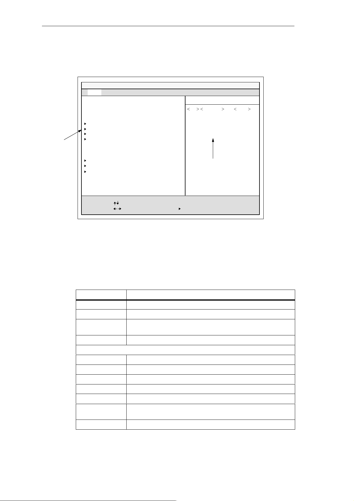
5.2 The Main Menu
Advanced
Selectable
submenu
Main Security Power Exit
System Time:
System Date:
Diskette A:
Primary Master
Primary Slave
Secondary Master
Secondary Slave
Memory Cache
PhoenixBIOS Setup Utility
[ 15:35:32 ]
[ 11/23/2000 ]
[ 1.44 MB, 31/2” ]
[20496 MB]
[None]
[None]
[None]
[WriteBack]
Configuring the SIMATIC Box PC 840
Boot Sequence Version
Item Specific Help
Shift-Tab Enter, or
Tab
selects field.
Example:
Hour/Minute/Second
Month/Day/Year
Boot Options
Keyboard Features
Hardware Options
System Memory:
Extended Memory:
F1 Help
ESC Exit
Figure 5-2 SETUP Main Menu
Setting in the Main Menu
In the Main menu, you can move upwards and downwards using the cursor keys
[↑] and [↓] to select the following system parameters:
Field Meaning
System Time For viewing and setting the current time
System Date For viewing and setting the current date
Diskette A Type of built in floppy disk drive
Memory Cache For setting cache options
by submenus
Primary Master Type of build in drives
Primary Slave Type of build in drives
Secondary Master Type of build in drives
Secondary Slave Type of build in drives
Boot Options For setting boot options
Keyboard
Features
Hardware Options For setting hardware options
Help window
640 KB
64512 KB
Select Item
Select Menu
+ / –
Change Values
Enter Select
Sub-MenuF9F10
Setup Defaults
Save and Exit
With LS 240 drive [Disabled]
For setting keyboard interface options (for example, NUM Lock,
Typematic Rate)
SIMATIC Box PC 840 Manual
A5E00085984-04
5-5
Page 88
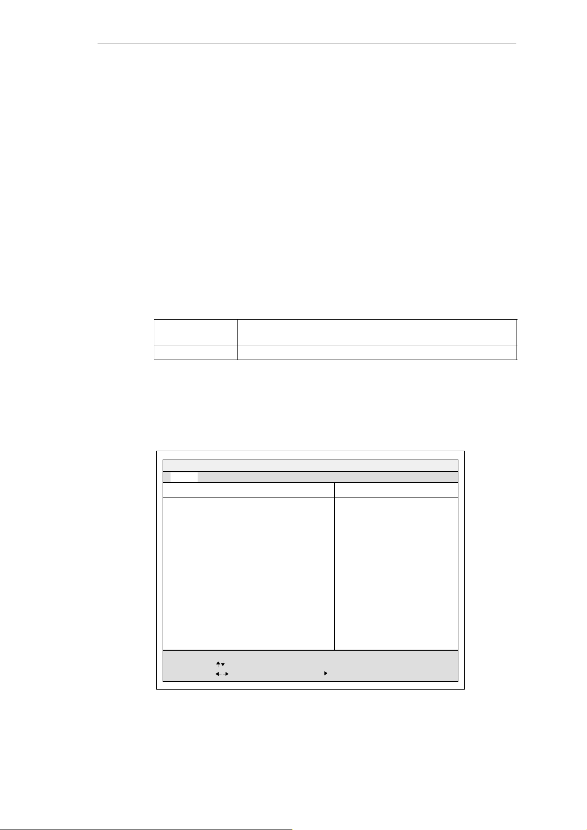
Configuring the SIMATIC Box PC 840
System Time und System Date Time and Date
System Time and System Date indicate the current values. Once you have
selected the appropriate option, you can use the [+] and [–] keys to modify the time
setting
Hour:Minute:Second
and the date
Month/Day/Year.
You can move between the entries in the date and time options (for example, from
hour to minute) using the tabulator key.
Diskette A Disk Drive
The type of floppy drive installed in the PC is set here. The following entries are
possible:
[Disabled] If there is no disk drive or LS 240 drive. Default setting for an installed
LS 240 drive.
[1.44 MB, 3 1/2”] Default setting for an installed disk drive A
Primary Master Primary Slave Secondary Master/ Secondary Slave
The system jumps to the following submenu when you select this type of menu
field:
PhoenixBIOS Setup Utility
Main
Primary Master [4326MB]
Type: [Auto]
LBA Format
Total Sectors
Maximum Capacity
Multi-Sector Transfers:
LBA Mode Control:
32 Bit I/O:
Transfer Mode:
Ultra DMA Mode:
[40031712]
20496MB
[16 Sectors]
[Enabled]
[Enabled]
[FPIO 4 / DMA 2]
[Mode2]
Item Specific Help
[AUTO] (recommended)
Autotypes installed
IDE-devices
[USER]
Enter parameters of
IDE-devices installed
at this connection
5-6
F1 Help
ESC Exit
Select Item
Select Menu
Figure 5-3Primary Master
+ / –
Change Values F9
Enter Select
Sub-Menu
Setup Defaults
F10
Save and Exit
SIMATIC Box PC 840 Manual
A5E00085984-04
Page 89

“Type” Field
The parameters you can select here are usually stored on the IDE drive. The ’Auto’
setting in the ’Type’ field means that these values are automatically read from the
drive and written into memory (Autodetect).
If Type is selected for a drive that cannot be detected, a timer times out in
approximately 1 minute and the entries remain unchanged. You should always
check that the interfaces for which you select ’Auto’ are in fact connected to drives.
Select “User” if you want to define the hard-disk type yourself, in which case
remember that you also have to set the other fields, including Cylinder, Heads,
Sectors/Track or other settings according to the type of hard disk.
“Multi Sector-Transfer” Field
The entry in the Multi-Sector Transfer field defines the number of sectors
transferred per interrupt. The value depends on the drive and should be set only by
setting the Type field to Auto.
Configuring the SIMATIC Box PC 840
Disabled
2,4,8,16 sectors
“LBA Mode Control” Field
If the LBA Mode Control field (enabled,disabled) is set to ’Enabled’, the system
supports hard disks with capacities greater than 528 Mbytes. The value depends
on the drive and should be set only by setting the Type field to Auto.
“32 Bit-IO” Field
The setting in the 32 Bit I/O field defines the mode of access for the drive
Disabled 16-Bit access
Enabled 32-Bit access (default)
“Transfer Mode” and “Ultra DMA Mode” Fields
The settings in these fields define the interface data-transfer rate. The value
depends on the drive and should be set only by setting the Type field to Auto.
Hit ESC to exit the submenu.
SIMATIC Box PC 840 Manual
A5E00085984-04
5-7
Page 90
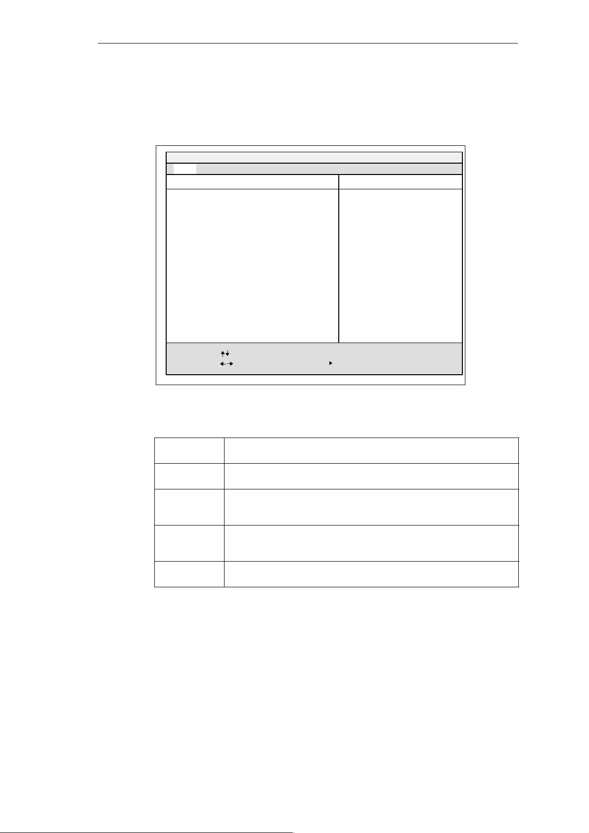
Configuring the SIMATIC Box PC 840
”Boot Options” Field
The following submenu appears when you select the “Boot Options” field in the
main menu:
Main
Boot Options
PhoenixBIOS Setup-Utility
Item Specific Help
QuickBoot Mode:
SETUP prompt: [Enabled]
POST Errors: [Enabled]
Floppy check: [Disabled]
Summary screen: [Enabled]
F1 Help
ESC Exit
[Enabled]
Select Item
Select Menu
+ / –
Change Values F9
Enter Select
Sub-Menu
Allows the system to skip
certain tests while booting.
This will decrease the time
needed to boot the system.
Setup Defaults
F10
Save and Exit
Figure 5-4”Boot Options” Submenu
Quick Boot
Some hardware tests are skipped to speed up the boot procedure.
Mode
SETUP prompt The message PRESS <F2> to enter Setup appears at the bottom of the
screen during the system run-up phase.
POST Errors The boot process is stopped if an error is detected; you must press F1 to
acknowledge. Enter “Disabled” to avoid the necessity of acknowledging
errors, for example, if no keyboard is connected.
Floppy check The floppy head is stepped inward and then back to its original position
during the system run-up phase. This test is useful because it
reinitializes the drive.
Summary
screen
The most important system parameters are displayed when the system
run-up phase completes.
5-8
’Enabled’ means that the feature is active. ’Disabled’ means that the feature is
inactive.
SIMATIC Box PC 840 Manual
A5E00085984-04
Page 91
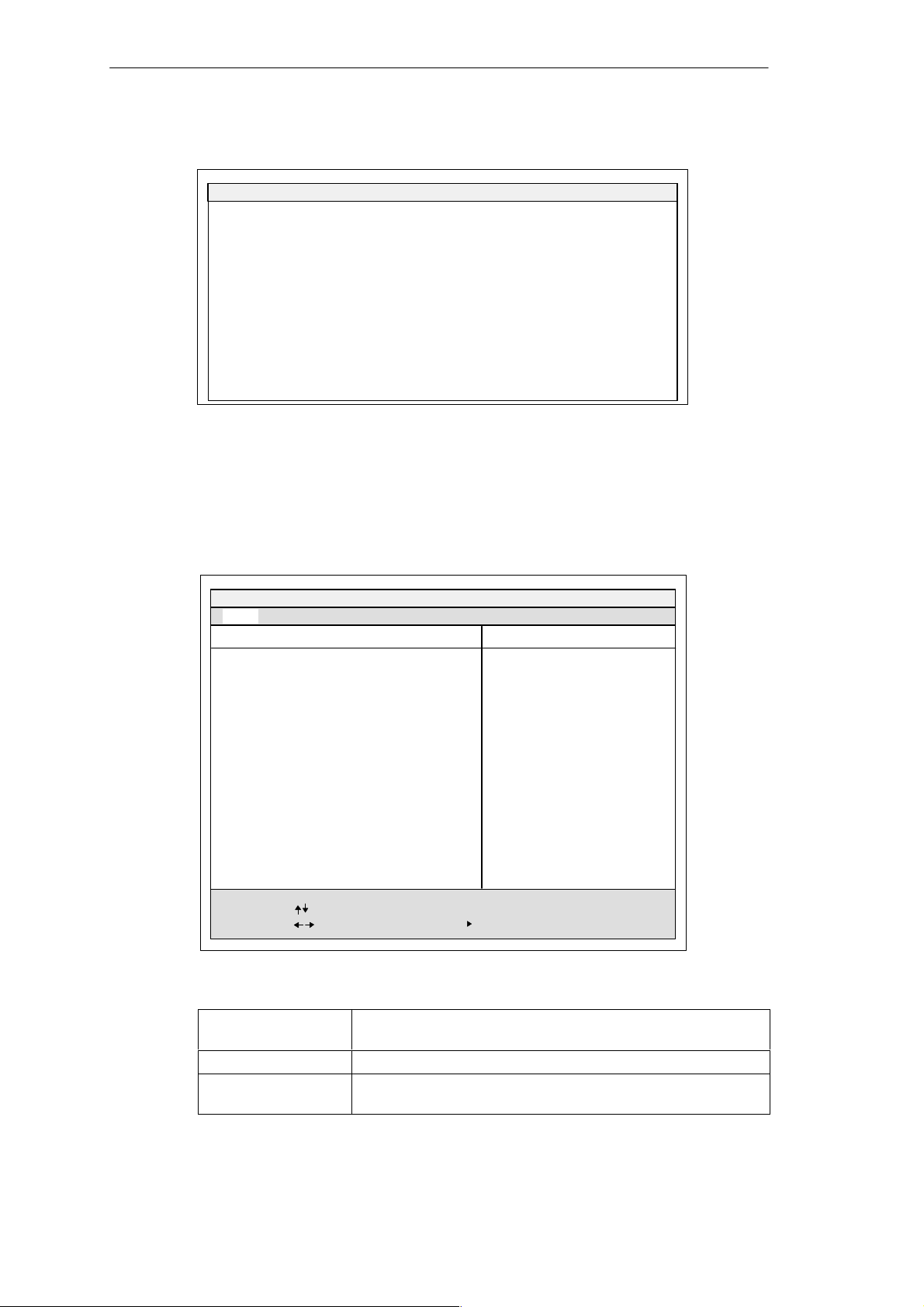
Configuring the SIMATIC Box PC 840
Example of a summary screen:
PhoenixBIOS Set Up Utility
SIMATIC Box PC 840 BIOS Version: V10.01.02.
CPU:
CPU Speed xxxx MHz
System 640 KB
Extended 127 MB
Shadow RAM: 384 KB
Cache RAM: 512 kB
Pentium
PIII
System ROM:
BIOS Date: 01/29/01
COM Ports: 03F8, 02F8
LPT Ports: 0378
Display Type: VGA
PS/2 Mouse: Installed
Fxx – FFFF
Hard Disk 0: 20496 MB
Hard Disk 1: None
Hard Disk 2:
Hard Disk 3: None
Figure 5-5Summary Screen
The Summary screen appears when the system run-up phase completes.
“Keyboard Features” Field
The following submenu appears if you select the “Keyboard Features” field in the
main menu:
Main
Numlock:
Key Click: [Disabled]
Keyboard auto-repeat rate: [30/sec]
Keyboard auto-repeat delay: [1/2 sec]
None
PhoenixBIOS Setup Utility
Keyboard Features
[On]
Diskette A: 1.44 MB, 31/2 ”
Item Specific Help
Selects Power-on state for
Numlock on next boot
F1 Help
ESC Exit
Figure 5-6”Keyboard Features” Submenu
Numlock
Key Click A keystroke can be heard
Keyboard auto-repeat
rate
SIMATIC Box PC 840 Manual
A5E00085984-04
Select Item
Select Menu
+ / –
Change Values F9
Enter Select
Sub-Menu
Setup Defaults
F10
Save and Exit
Switches Numlock on or off following power on. If “Auto” is set,
this will be remembered the next time the device is switched on.
Increase in automatic key repeat rate
5-9
Page 92
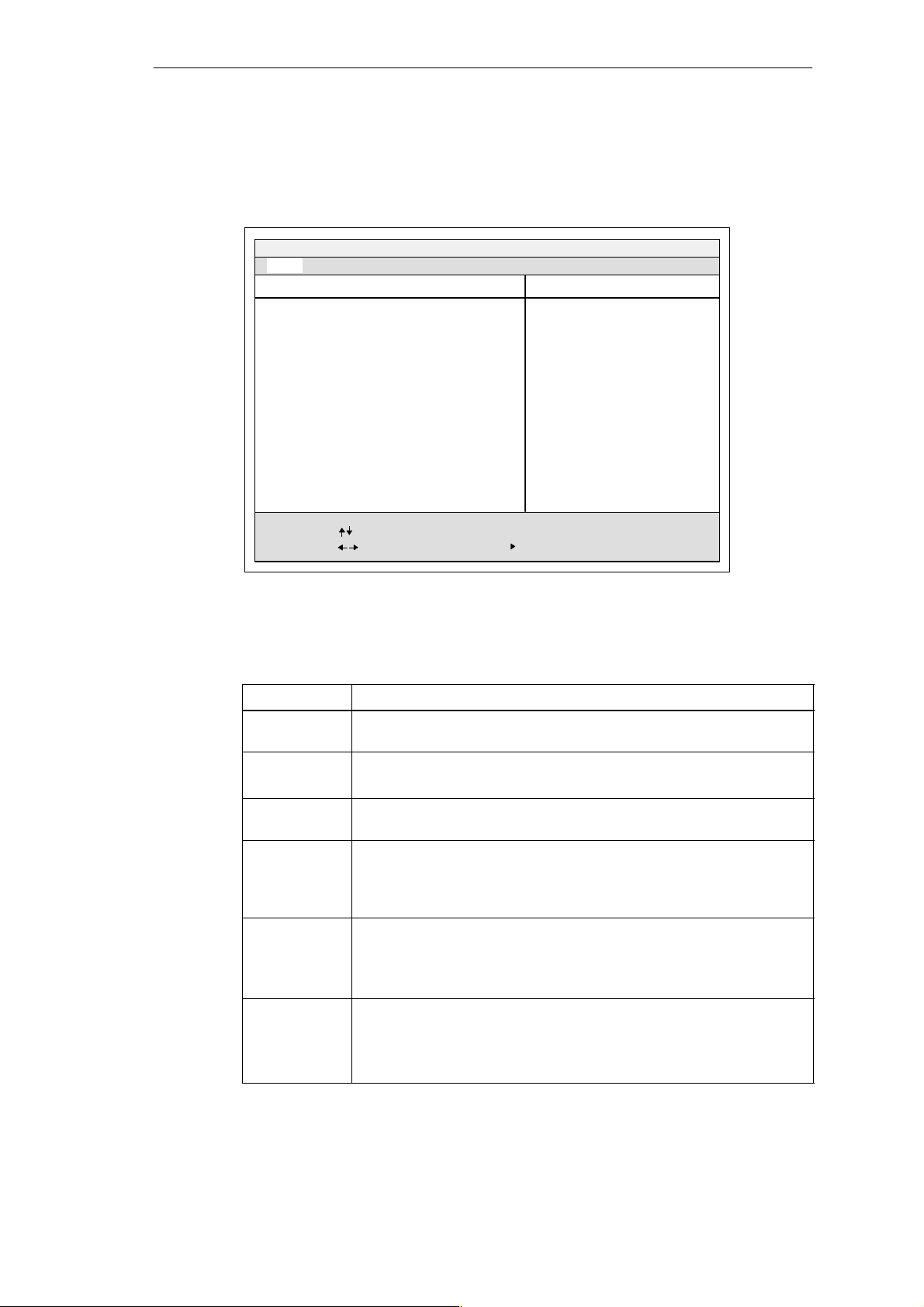
Configuring the SIMATIC Box PC 840
”Hardware Options” Field
The following submenu appears when you select the “Hardware Options” field in
the main menu:
Main
Hardware Options
PhoenixBIOS Setup-Utility
Item Specific Help
PCI - MPI / DP:
On Board Ethernet
Ethernet Adress: 080006247000
LAN Remote Boot: [Enabled]
Legacy USB Support:
SafeCard functions:
Fan Control:
CRT / LCD selection:
LCD-Screensize:
PS/2 Mouse:
F1 Help
ESC Exit
[Enabled]
[Enabled]
[Disabled]
[Enabled]
[Enabled]
[SIMULTAN]
[Graph& Text Expand]
[Enabled]
Select Item
Select Menu
Enable or disable the
PCI - Multi Point
Interface (MPI / DP)
+ / –
Change Values F9
Enter Select
Sub-Menu
Setup Defaults
F10
Save and Exit
Figure 5-7”Hardware Options” Submenu
The parameters of the interfaces present on the motherboard are set here.
Entry Meaning
PCI-MPI/DP *1Enables the CP5611-compatible MPI/DP interface. The resourses are
managed by the BIOS PCI Plug and Play mechanism.
On Board
Ethernet
Ethernet
Address
LAN Remote
Boot
Legacy USB
Support
SafeCard
functions
[Enabled] The Ethernet port on the motherboard is enabled.
[Disabled] The Ethernet port on the motherboard is disabled.
The individual Ethernet address is entered here.
[Enabled] Booting using a connected LAN is possible. The
respective boot source is displayed as
Intel Boot-Agent in the boot sequence menu.
[Disabled] Booting using LAN is not possible.
[Disabled] Default setting for operating system with its own
USB support.
[Enabled] This setting makes it possible for non-USB capable
operating systems to be used.
[Enabled] On board monitoring functions are enabled.
[Disabled] No monitoring functions.
The relevant driver and the application must be started for operation of
the monitoring functions.
5-10
*1Optional product feature
SIMATIC Box PC 840 Manual
A5E00085984-04
Page 93

Configuring the SIMATIC Box PC 840
Entry Meaning
Fan Control [Enabled] Fan speed depends on temperature.
[Disabled] Fan always runs at full speed.
CRT / LCD
selection
LCD-Screensize
PS/2 Mouse [Enabled] The PS/2 port is activated. This is the default for the
[LCD Enabled] All data is output only to the internal LCD,
the 15-way VGA port is disabled
[CRT Enabled] For maximum resolution the display signals are output
only to the 15-way VGA port; the LCD interface of the
VGA controller is disabled.
[SIMULTAN] Both display interfaces are enabled and operate
simultaneously. Note, however, that the LCD does not
support all resolutions.
[Normal] The display window in Text and Graphic modes is not
expanded to full screen size.
[Text expand] Only the Text modes are expanded to full screen size.
[Graphic expand]Only the Graphic modes are expanded to full screen
size.
[Graph&Text
expand] The Graphic and Text modes are expanded to full
screen size.
SIMATIC Box PC 840, the PS/2 mouse is activated in
this setting. IRQ 12 is assigned.
[Disabled] The PS/2 port is deactivated, IRQ12 is available.
Note: Invariably, changes to this interface do not come into
effect until the PC is switched off and on again.
SIMATIC Box PC 840 Manual
A5E00085984-04
5-11
Page 94
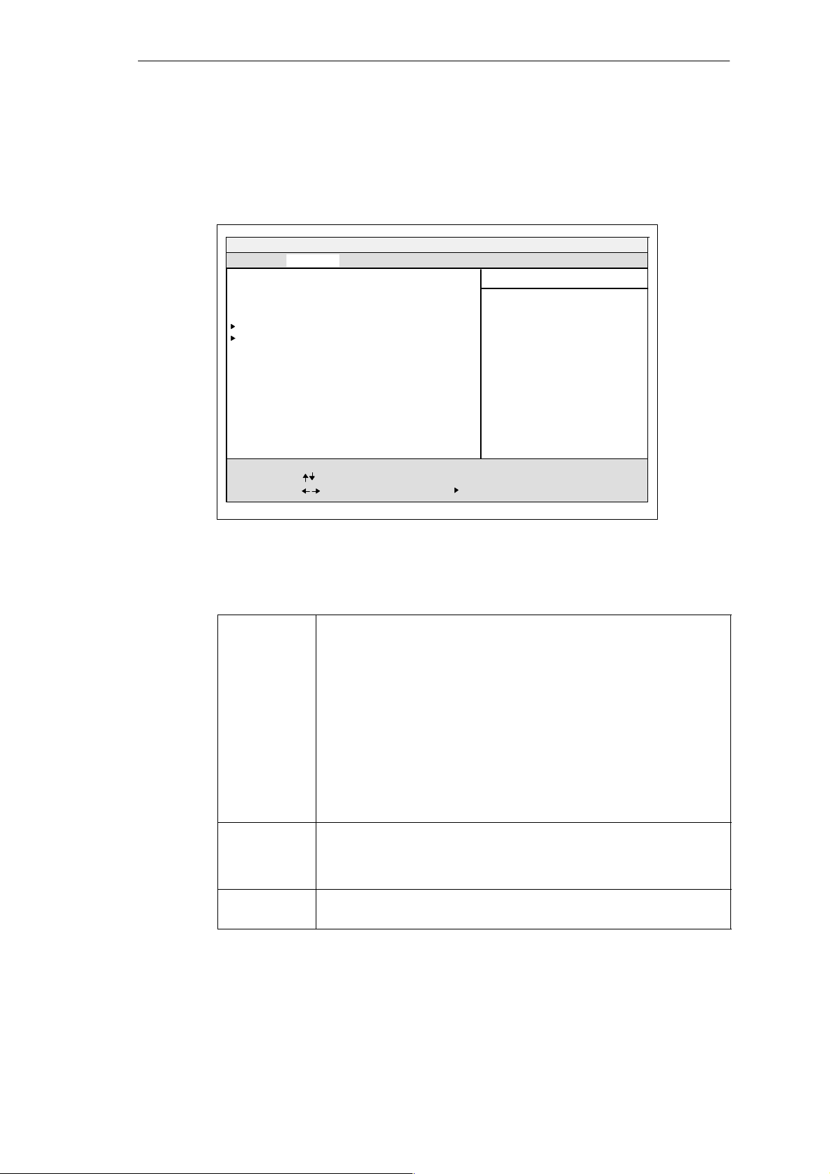
Configuring the SIMATIC Box PC 840
5.3 The Advanced Menu
Menu Structure
Main Security Power
Setting items on this menu to incorrect values may
cause your system to malfunction
COM/LPT Configuration
PCI Configuration
Installed O/S:
Reset Configuration Data: [Yes]
Floppy Disk Controller:
Large Disk Access Mode:
Local Bus IDE adapter:
Memory Gap at 15 Mbyte: [Disabled]
Default Primary Video Adapter [AGP]
Advanced
Setup Warning
PhoenixBIOS Setup-Utility
[Other]
[Enabled]
[DOS]
[Primary & Secondary]
ExitBoot Sequence Version
Item Specific Help
Select the operating system
installed on your system which
you will use most commonly.
Note: An incorrect setting can
cause some operating systems
to display unexpected behavior.
F1 Help
ESC Exit
Select Item
Select Menu
Figure 5-8 ”Advanced” Menu
Setting in the Advanced Menu
Installed O/S Plug and Play means that all modules are automatically detected and
installed, providing they support the Plug and Play functionality.
[other] BIOS handles the entire Plug and Play capability, default
[Win95] BIOS handles the entire Plug and Play capability, default
[Win98] The operating system handles some of the Plug and Play
[WinMe] The operating system handles some of the Plug and Play
[Win2000] The operating system handles some of the Plug and Play
Reset
Configuration
Data
Floppy disk
controller
[Yes] All installations under Plug and Play are deleted and
[Enabled] The floppy disk controller is switched on.
[Disabled] With LS 240 the floppy disk controller is switched off.
+ / –
Change Values F9
Enter Select
Sub-Menu
Setup Defaults
F10
Save and Exit
configuration
configuration
functions
functions
functions
reconfiguration is triggered the next time the system boots.
The entry is then reset to [No]. System components that do
not support Plug and Play have to be entered manually.
5-12
SIMATIC Box PC 840 Manual
A5E00085984-04
Page 95
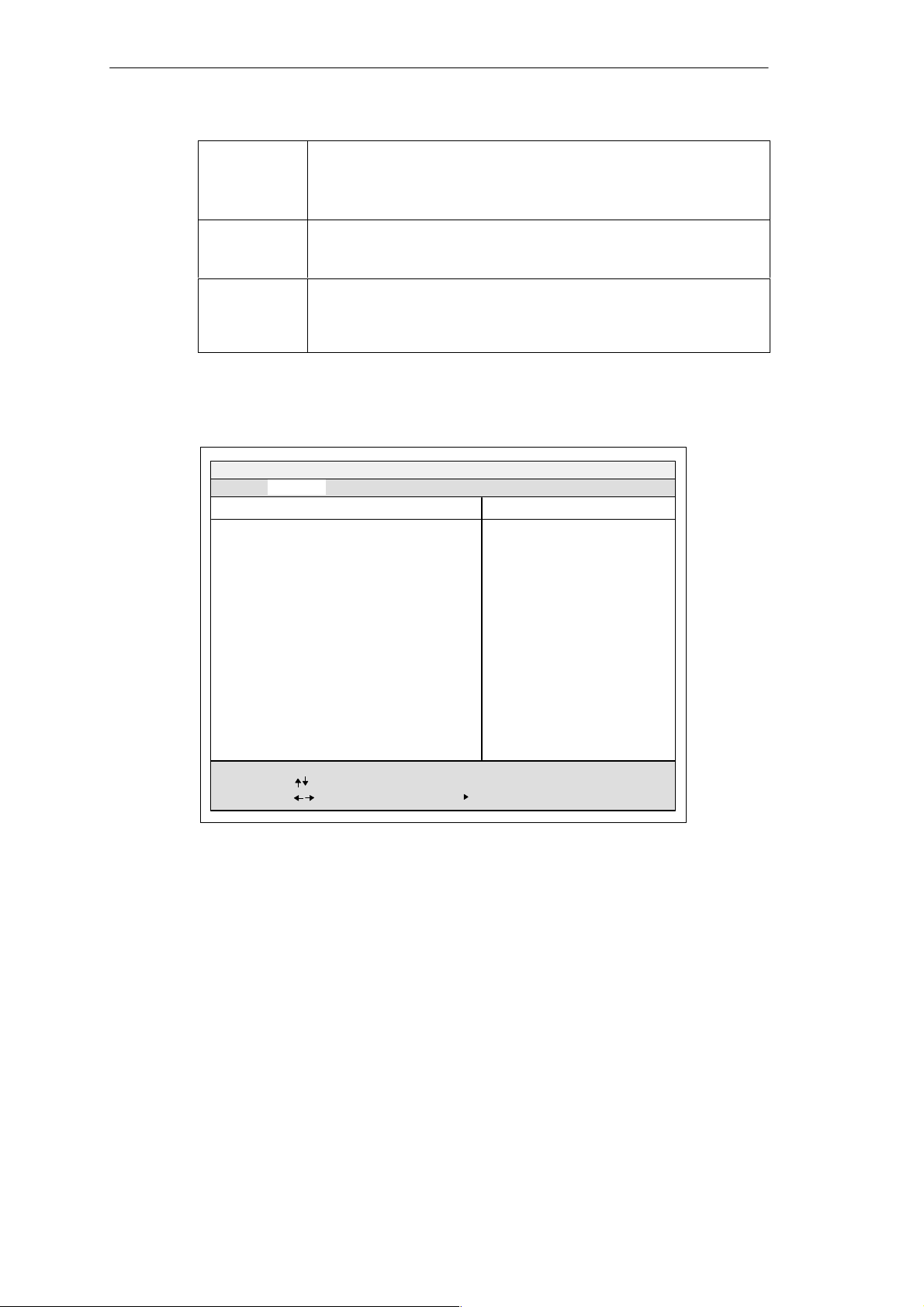
Configuring the SIMATIC Box PC 840
Local Bus IDE
adapter
[Primary] One IDE interface for max. two drives.
[Secondary]
[Primary & Secondary] Two IDE interfaces for max. four drives.
[Disabled] No local IDE interface.
Large Disk
Access Mode
[DOS] The drive tables are adapted for DOS access operations
in accordance with Enhanced IDE.
[OTHER] The tables are not adapted.
Memory Gap at
15 MByte
[Disabled] The complete onboard RAM memory is available.
[Enabled] A 1MB area of the RAM above 15MB
(Addresses F0 0000 – FF FFFF) can be used by ISA
expansion cards.
“COM/LPT Configuration” Submenu
PhoenixBIOS Setup Utility
Advanced
COM / LPT Configuration
Internal COM 1:
Base I/O address:
Interrupt: [IRQ 4]
COM 1 TTY
Internal COM2:
Base I/O address:
Interrupt: [IRQ 3]
Internal LPT1:
Mode:
Base I/O address: [378]
Interrupt: [IRQ 7]
[Enabled]
[3F8]
[Disabled]
[Enabled]
[2F8]
[Enabled]
[Bi-directional]
Item Specific Help
Configure internal COM
port using options:
[Disabled]
No configuration
[Enabled]
User configuration
[Auto]
BIOS or OS chooses
configuration
[OS Controlled]
Controlled by OS
F1 Help
ESC Exit
Select Item
Select Menu
+ / –
Change Values F9
Enter Select
Sub-Menu
Setup Defaults
F10
Save and Exit
Figure 5-9”COM / LPT configuration” Submenu
The resources used by an interface are released when you disable the interface in
question.
The I/O addresses and interrupts are preassigned: it is advisable not to change
these default assignments.
SIMATIC Box PC 840 Manual
A5E00085984-04
5-13
Page 96
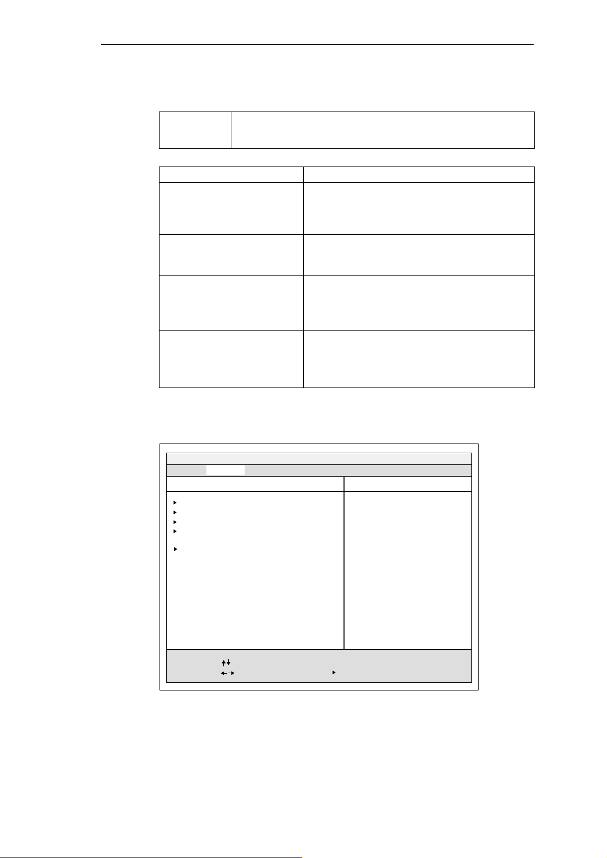
Configuring the SIMATIC Box PC 840
Printer Port Internal LPT1
Mode: Use this setting to set the operating mode of the printer interface. Refer
to the table below to ensure that the setting matches the printer
connected to the printer port.
Settable Mode Features
Output Only
Standard parallel port –
unidirectional (SPP)
Bidirectional
Standard parallel port –
bidirectional
EPP
Enhanced parallel port
ECP
Extended capability port
Standard setting for the 8 bit parallel transfer
according to IEEE1284 specifications
Feedback of the output device is only possible via
the control cables
as for SPP – unidirectional, however:
Feedback of the output device is also possible via
the 8 bit data cables
Enhanced parallel port (data transfer rate from
500kbps up to 2Mbps)
Hardware handshake
different devices can be addressed
as for EPP, however:
own DMA channel
FIFO backup
Data compression
“PCI Configuration” Submenu
Advanced
PCI Configuration
PCI Device, Slot #1
PCI Device, Slot #2
PCI Device, Slot #3
PCI Device, Slot #4
PCI/PNP ISA IRQ Resource Exclusion
PCI IRQ line 1:
PCI IRQ line 2:
PCI IRQ line 3:
PCI IRQ line 4:
F1 Help
ESC Exit
Figure 5-10 ”PCI Configuration” Submenu
Select Item
Select Menu
PhoenixBIOS Setup Utility
[Auto Select]
[Auto Select]
[Auto Select]
[Auto Select]
+ / –
Change Values F9
Enter Select
Item Specific Help
Setup items for configuring The
specific PCI device
Setup Defaults
Sub-Menu
F10
Save and Exit
5-14
SIMATIC Box PC 840 Manual
A5E00085984-04
Page 97
”PCI Devices” Field
If the PCI devices field is selected, the following submenu appears:
Option Rom Scan [Enabled]
Enable Master: [Enabled]
Latency Timer: [0040h]
Advanced
PCI Devices, Slot #1
PhoenixBIOS Setup Utility.
Item Specific Help
Configuring the SIMATIC Box PC 840
Initialize device expansion
rom
F1
ESC
Help
Exit
Select Item
Select Menu
+ / –
Change Values F9
Enter Select
Sub-Menu
Setup Defaults
F10
Save and Exit
Figure 5-11 Submenu ”PCI Devices, Slot #1”
Option ROM
Scan:
[Enabled] The option ROM of the PCI module (if present) is
enabled
[Disabled] The option ROM of a PCI module is disabled.
Enable Master: [Enabled] This slot can assume the PCI master function
[Disabled] This slot can only operate as a PCI slave.
Latency Timer [Default] The number of active PCI clock cycles of the master
modules are determined by the module
[0020H With these settings, the maximum active PCI clock
to cycles are set to the selected value.
00E0H]
SIMATIC Box PC 840 Manual
A5E00085984-04
5-15
Page 98
Configuring the SIMATIC Box PC 840
“PCI/PNP ISA IRQ Resource Exclusion” Submenu
Available means that the Plug and Play mechanism in BIOS can allocate the IRQ
to Plug and Play submodules or motherboard functions.
Use the ’Reserved’ setting only if the interrupt has to be assigned specifically to
PCMCIA submodules with no Plug and Play capability.
PhoenixBIOS Setup Utility.
Advanced
PCI / PNP ISA IRQ Resource Exclusion
Item Specific Help
IRQ 3:
IRQ 4:
IRQ 5:
IRQ 9:
IRQ 10:
IRQ 11:
IRQ 12:
F1 Help
ESC Exit
[Available]
[Available]
[Available]
[Available]
[Available]
[Reserved]
[Available]
Select Item
Select Menu
+ / –
Change Values F9
Enter Select
Reserves the specified
IRQ for use by legacy
ISA devices
Sub-Menu
Setup Defaults
F10
Save and Exit
Figure 5-12 ”PCI / PNP ISA IRQ Resource Exclusion” Submenu
5-16
SIMATIC Box PC 840 Manual
A5E00085984-04
Page 99
“PCI IRQ line” Field
PCI/PNP ISA Resource Exclusion
PCI IRQ line 1:
PCI IRQ line 2:
PCI IRQ line 3:
PCI IRQ line 4:
Advanced
PCI Configuration
PhoenixBIOS Setup Utility.
Disabled
Auto Select
3
4
5
7
9
10
11
12
14
15
Configuring the SIMATIC Box PC 840
Item Specific Help
PCI devices can use
hardware interrupts
called IRQs. A PCI
device cannot use IRQs
already in use by ISA or
EISA devices. Use ’Auto’
only if no ISA or EISA
legacy cards are installed
F1 Help
ESC Exit
Select Item
Select Menu
+ / –
Change Values F9
Enter Select
Sub-Menu
Setup Defaults
F10
Save and Exit
Figure 5-13 ”PCI Configuration” Submenu
Disabled
No interrupt possible for this PCI-IRQ line
AutoSelect Plug and Play mechanism in BIOS selects unassigned interrupts and
allocates them to the on-board PCI devices.
3 to 15 The PCI-IRQ line is assigned to the selected interrupt.
Do not use this setting unless it is specifically required in your application
documentation.
Assignment of the PCI IRQ lines to the PCI slots.
Box PC 840 PCI Module Interrupt Assignment (PCI-IRQ) in:
Module Interrupt
(Pin No.)
INT – A (A6) line 1 line 2 line 3 line 4
INT – B (B7) line 2 line 3 line 4 line 1
INT – C (A7) line 3 line 4 line 1 line 2
INT – D (B8) line 4 line 1 line 2 line 3
Slot 1 Slot 2 Slot 3 Slot 4
gray highlighting indicates slot module main interrupt
SIMATIC Box PC 840 Manual
A5E00085984-04
5-17
Page 100
Configuring the SIMATIC Box PC 840
5.4 The Security Menu
You can only edit the fields enclosed in square brackets. Two passwords are
assigned to protect your PC from unauthorized use. You can use the supervisor
password to prevent use of diskettes for the normal user and to limit use of the
hard disk.
Main Security PowerAdvanced ExitBoot Sequence Version
Supervisor Password is Disabled
User Password is Disabled
Set Supervisor Password
Set User Password [Enter]
Password on boot: [Disabled]
Fixed disk boot sector: [Normal]
Diskette access: [Supervisor]
PhoenixBIOS Setup-Utility
Item Specific Help
Supervisor Password controls
access to the setup utiliy
[Enter ]
F1 Help
ESC Exit
Select Item
Select Menu
+ / –
Enter Select
Figure 5-14 ”Security” Menu
User Password
is
Disabled Password is active. BIOS Setup cannot be opened until
the password has been entered.
Enabled Certain Setup fields are thus configurable by the user,
including the user password.
The field resets automatically from [Disabled] to [Enabled] when the
password is entered.
Set Supervisor
Password
This field opens the dialog box for entering a password. Once it has been
entered, the supervisor password can be changed or deleted by
pressing ”Return” and thus deactivated.
Set User
Password
This field opens the dialog box for entering a password. Once it has been
entered correctly, the user password can be changed or deleted by
pressing ”Return” and thus deactivated.
Password on
boot
[Disabled] No password required for system boot.
[Enabled] Supervisor or user password must be entered for system
boot.
Fixed disk boot
Sector
[Normal] All types of hard-disk access are permitted.
[Write protect]No operating system can be installed.
This is a way of protecting against boot viruses.
Change Values F9
Sub-Menu
F10
Setup Defaults
Save and Exit
5-18
SIMATIC Box PC 840 Manual
A5E00085984-04
 Loading...