

Page 1

Preface, Table of Contents
SIMATIC
SIMATIC Box PC 620
Manual
Product Overview
Commissioning the SIMATIC Box
PC 620
Welcome to the SIMATIC Box PC 620
Setting-up and Operating
the SIMATIC Box PC 620
SIMATIC Box PC 620 Expansions
Configuring the SIMATIC Box PC 620
Error Diagnosis
Hardware Information
Appendix
1
2
3
4
5
6
7
8
Edition 08/2001
C79000-G7076-C639-04
Guidelines for ESD
Glossary, Index
A
Page 2

Safety information
This manual contains information which you must observe for your personal safety and to
prevent material damage. The information is denoted by a warning triangle and is represented
as follows, depending on the degree of endangerment:
Warning
!
!
Qualified personnel
means that death, serious injury or considerable material damage can result, if the appropriate
safety precautions are not taken.
Caution
means that slight injury or material damage can result, if the respective safety precautions are
not taken.
Note
is an important piece of information about the product, the handling of the product or the
respective part of the documentation which should be noted in particular.
Only qualified personnel may make changes to the device on the basis of the technical
description. Qualified personnel are persons, who have the authorisation to install, ground and
label, devices, systems and circuits in accordance with the standards of safety engineering.
As directed use
Please note the following:
Warning
!
Trademarks
The device may only be used for the application cases specified in the catalogue and the
technical description and may only be used in combination with extraneous equipment and
components recommended or approved by Siemens.
Appropriate transport, appropriate storage, installation and assembly as well as careful
operation and maintenance are required to ensure that the product operates perfectly and
safely.
SIMATIC, SIMATIC HMI and SIMATIC NET are registered trademarks of Siemens AG.
The remaining marks in this publication may be trademarks, whose use by third parties for their
own purposes could violate the rights of the owner.
Exclusion of liabilityCopyright Siemens AG 2000 All rights reserved
The transmission and reproduction of this documentation and the
exploitation and communication of its contents are not allowed,
unless expressly granted. Contraventions are liable to
compensation for damage. All rights reserved, especially in the case
of the granting of a patent or registration by GM.
Siemens AG
Bereich Automatisierungs- und Antriebstechnik
Geschäftsgebiet Industrie-Automatisierungssysteme
Postfach 4848, D- 90327 Nürnberg
Siemens Aktiengesellschaft C79000-G7076-C639
We have checked the content of this publication for compliance with the
described hard- and software. However, discrepancies cannot be
excluded, with the result that we assume no guarantee for total
compliance. The information in this publication is checked regularly, and
any necessary corrections are included in the following editions. We
would be grateful for any suggestions for improvement
Siemens AG 2000
Subject to technical change.
.
Page 3

Preface
What this Manual is About
This manual contains all the information you need for working with the SIMATIC
Box PC 620 programming device. You can use it to
unpack the programming device and power it up.
familiarize yourself with the functions and settings of the various components
(display, keyboard, programming facilities etc.).
connect the programming device up to other units of equipment (programmable
controllers, other programming devices).
expand your system, provided you comply with the necessary conditions.
analyze and eliminate simple faults.
Who is the Manual Intended For?
The following persons require the manual:
Users commissioning the programming device themselves or working with it
(editing, programming or debugging).
System administrators operating the programming device in a network.
Service and maintenance personnel using the SIMATIC Box PC 620 for system
expansion purposes or error/fault analysis.
Scope of the manual
The content of this manual describes the as delivered condition of the
SIMATIC Box PC 620 for January 2000. You will find the currently valid technical
data for your device in the operating manual which is supplied with the device.
Approvals
You will find the approvals, certificates and certifications valid for your device in
Chapter 1 of the operating manual.
Product name SIMATIC Box PC 620
The abbreviation PC is also used in this publication for the product name
SIMATIC Box PC 620.
SIMATIC Box PC 620 Manual
C79000-G7076-C639-04
iii
Page 4

Preface
Information Classification
The following publication is enclosed with your SIMATIC Box PC 620 which
enables you to carry out initial installation and commissioning:
The operating manual of the SIMATIC Box PC 620 with the applicable
technical data and software.
Please refer to the associated manuals for further directions for handling the software.
Pointers through the Manual
The manual contains in the Chapters 1 to 4 the most important instructions for
starting up and using the programming device of the SIMATIC BOX PC 620.
Chapters 5 to 8 are reference sections you will require only in special cases.
Installation
Before you use the SIMATIC BOX PC 620 for the first time, read Chapter 2 about
the possibilities for assembly and installation on the SIMATIC Box PC 620’s
components and functionality.
Start up
Chapter 4 describes the basics steps necessary for starting up the
SIMATIC BOX PC 620.
Expansion
Chapter 4 describes how to expand your SIMATIC BOX PC 620 (e.g. installation of
memory expansions). Please observe the safety notes.
Configuration
Modifications to the system hardware may make it necessary for you to adapt the
original hardware configuration. Chapter 6 tells how to proceed in this case.
Error/Fault Dignostics
Chapter 7 will tell you how to deal with simple faults that you can diagnose and, in
some cases, eliminate yourself.
Reference Data
Chapter 8 contains hardware addresses, interrupt assignments and information on
connecting cables.
ESD instructions
The instructions for handling electrostatic sensitive devices are of particular importance for service and maintenance engineers who install expansions or carry out
error analysis with the SIMATIC Box PC 620.
Glossary
The glossary explains important terms.
SIMATIC Box PC 620 Manual
iv
C79000-G7076-C639-04
Page 5

Alphbetical Index
The index will enable you to quickly find passages in the text pertaining to
important keywords.
Further support
Please contact your Siemens contact person at a maintenance and repair location
or the SIMATIC hotline iif you have any questions about using the
SIMATIC Box PC 620 which are not answered in the manual. You will find the
addresses in the operating manual.
Preface
SIMATIC Box PC 620 Manual
C79000-G7076-C639-04
v
Page 6

Preface
SIMATIC Box PC 620 Manual
vi
C79000-G7076-C639-04
Page 7

Table of contents
Preface iii. . . . . . . . . . . . . . . . . . . . . . . . . . . . . . . . . . . . . . . . . . . . . . . . . . . . . . . . . . . . . . . .
1 Product Overview 1-1. . . . . . . . . . . . . . . . . . . . . . . . . . . . . . . . . . . . . . . . . . . . . . . . . . . . . .
2 Commissioning the SIMATIC Box PC 620 2-1. . . . . . . . . . . . . . . . . . . . . . . . . . . . . . . . .
2.1 Unpacking and Checking the Scope of Delivery 2-2. . . . . . . . . . . . . . . . . . . . .
2.2 Installing the SIMATIC Box PC 620 2-3. . . . . . . . . . . . . . . . . . . . . . . . . . . . . . . .
2.3 Preparing for Operation 2-9. . . . . . . . . . . . . . . . . . . . . . . . . . . . . . . . . . . . . . . . . .
2.4 Transport 2-11. . . . . . . . . . . . . . . . . . . . . . . . . . . . . . . . . . . . . . . . . . . . . . . . . . . . . . .
3 Welcome to the SIMATIC Box PC 620 3-1. . . . . . . . . . . . . . . . . . . . . . . . . . . . . . . . . . . .
3.1 Right-Hand Side of the Device (Port Side) 3-2. . . . . . . . . . . . . . . . . . . . . . . . . .
3.2 Left-Hand Side of the Device (Drive Side) 3-4. . . . . . . . . . . . . . . . . . . . . . . . . .
3.3 Ports 3-5. . . . . . . . . . . . . . . . . . . . . . . . . . . . . . . . . . . . . . . . . . . . . . . . . . . . . . . . . .
3.4 PC Card Port 3-7. . . . . . . . . . . . . . . . . . . . . . . . . . . . . . . . . . . . . . . . . . . . . . . . . . .
3.5 Drives 3-9. . . . . . . . . . . . . . . . . . . . . . . . . . . . . . . . . . . . . . . . . . . . . . . . . . . . . . . . .
3.5.1 Disk Drive (Depending on the Device Configuration) 3-9. . . . . . . . . . . . . . . . .
3.5.2 LS 120 Drive (Depending on Device Configuration) 3-10. . . . . . . . . . . . . . . . . .
3.5.3 Hard Disk Drive 3-11. . . . . . . . . . . . . . . . . . . . . . . . . . . . . . . . . . . . . . . . . . . . . . . . .
3.5.4 CD-ROM Drive (Depending on the Device Equipment) 3-11. . . . . . . . . . . . . . .
3.6 Backup Battery 3-14. . . . . . . . . . . . . . . . . . . . . . . . . . . . . . . . . . . . . . . . . . . . . . . . .
4 Setting Up and Operating the SIMATIC Box PC 620 4-1. . . . . . . . . . . . . . . . . . . . . . .
4.1 Connecting the SIMATIC Box PC 620 to the Power Supply 4-2. . . . . . . . . . .
4.2 Connecting Peripheral Devices 4-5. . . . . . . . . . . . . . . . . . . . . . . . . . . . . . . . . . . .
4.3 Working with PC Cards 4-10. . . . . . . . . . . . . . . . . . . . . . . . . . . . . . . . . . . . . . . . . .
4.4 Connecting the SIMATIC Box PC 620 to other SIMATIC S5 4-13. . . . . . . . . . .
4.5 Connecting the SIMATIC Box PC 620 to a SIMATIC S7 Network
(MPI/DP) 4-18. . . . . . . . . . . . . . . . . . . . . . . . . . . . . . . . . . . . . . . . . . . . . . . . . . . . . . .
4.6 Networking the SIMATIC Box PC 620 with Other Stations on PROFIBUS 4-20
4.7 Networking the SIMATIC Box PC 620 and Other Computers on
Industrial Ethernet 4-21. . . . . . . . . . . . . . . . . . . . . . . . . . . . . . . . . . . . . . . . . . . . . . .
4.8 Connection under Windows 4-21. . . . . . . . . . . . . . . . . . . . . . . . . . . . . . . . . . . . . . .
SIMATIC Box PC 620 Manual
C79000-G7076-C639-04
vii
Page 8

Table of contents
5 SIMATIC Box PC 620 Expansions 5-1. . . . . . . . . . . . . . . . . . . . . . . . . . . . . . . . . . . . . . . .
5.1 Opening the Unit 5-2. . . . . . . . . . . . . . . . . . . . . . . . . . . . . . . . . . . . . . . . . . . . . . . .
5.1.1 Prerequisites 5-2. . . . . . . . . . . . . . . . . . . . . . . . . . . . . . . . . . . . . . . . . . . . . . . . . . .
5.1.2 Opening the SIMATIC BOX PC 620 5-4. . . . . . . . . . . . . . . . . . . . . . . . . . . . . . . .
5.1.3 Components Visible After Opening the Unit 5-5. . . . . . . . . . . . . . . . . . . . . . . . .
5.1.4 Block Diagram of the Motherboard 5-6. . . . . . . . . . . . . . . . . . . . . . . . . . . . . . . . .
5.1.5 The Motherboard 5-7. . . . . . . . . . . . . . . . . . . . . . . . . . . . . . . . . . . . . . . . . . . . . . . .
5.2 Installing Memory Expansion Submodules 5-9. . . . . . . . . . . . . . . . . . . . . . . . . .
5.3 Replacing the Backup Battery 5-11. . . . . . . . . . . . . . . . . . . . . . . . . . . . . . . . . . . . .
5.4 Installation of Expansion Cards 5-13. . . . . . . . . . . . . . . . . . . . . . . . . . . . . . . . . . . .
5.4.1 Removal and Installation of the Device for Holding Down the modules 5-15. .
5.4.2 Removal and Installation of an Expansion Card 5-17. . . . . . . . . . . . . . . . . . . . . .
5.5 Removal and Installation of Drives 5-18. . . . . . . . . . . . . . . . . . . . . . . . . . . . . . . . .
5.5.1 Removal and Installation of the Hard Disk Drive 5-18. . . . . . . . . . . . . . . . . . . . .
5.5.2 Removal and Installation of a CD-ROM Drive 5-20. . . . . . . . . . . . . . . . . . . . . . .
5.5.3 Removal and Installation of the Floppy Drive 5-21. . . . . . . . . . . . . . . . . . . . . . . .
5.5.4 Removal and Installation of the LS 120 Drive 5-22. . . . . . . . . . . . . . . . . . . . . . . .
5.6 Removal and Installation of the Power Supply Unit 5-23. . . . . . . . . . . . . . . . . . .
5.7 Removal and Installation of the Bus Board 5-24. . . . . . . . . . . . . . . . . . . . . . . . . .
5.7.1 Removal and Installation of the Motherboard 5-25. . . . . . . . . . . . . . . . . . . . . . . .
5.8 Removal and Installation of the Fan 5-26. . . . . . . . . . . . . . . . . . . . . . . . . . . . . . . .
5.9 Processor Upgrade 5-27. . . . . . . . . . . . . . . . . . . . . . . . . . . . . . . . . . . . . . . . . . . . . .
5.10 Switch Settings / Jumpers 5-28. . . . . . . . . . . . . . . . . . . . . . . . . . . . . . . . . . . . . . . .
5.11 Reset Button 5-29. . . . . . . . . . . . . . . . . . . . . . . . . . . . . . . . . . . . . . . . . . . . . . . . . . .
6 Configuring the SIMATIC Box PC 620 6-1. . . . . . . . . . . . . . . . . . . . . . . . . . . . . . . . . . . .
6.1 Changing the Device Configuration with SETUP 6-2. . . . . . . . . . . . . . . . . . . . .
6.1.1 The Main Menu 6-5. . . . . . . . . . . . . . . . . . . . . . . . . . . . . . . . . . . . . . . . . . . . . . . . .
6.1.2 The Advanced Menu 6-15. . . . . . . . . . . . . . . . . . . . . . . . . . . . . . . . . . . . . . . . . . . . .
6.1.3 The Security Menu 6-23. . . . . . . . . . . . . . . . . . . . . . . . . . . . . . . . . . . . . . . . . . . . . .
6.1.4 The Power Menu 6-25. . . . . . . . . . . . . . . . . . . . . . . . . . . . . . . . . . . . . . . . . . . . . . . .
6.1.5 The Boot Sequence Menu 6-27. . . . . . . . . . . . . . . . . . . . . . . . . . . . . . . . . . . . . . . .
6.1.6 The Version Menu 6-29. . . . . . . . . . . . . . . . . . . . . . . . . . . . . . . . . . . . . . . . . . . . . . .
6.1.7 The Exit Menu 6-30. . . . . . . . . . . . . . . . . . . . . . . . . . . . . . . . . . . . . . . . . . . . . . . . . .
6.1.8 Default Setup Settings 6-31. . . . . . . . . . . . . . . . . . . . . . . . . . . . . . . . . . . . . . . . . . .
6.2 Configuring the PC Card 6-34. . . . . . . . . . . . . . . . . . . . . . . . . . . . . . . . . . . . . . . . .
7 Error Diagnosis 7-1. . . . . . . . . . . . . . . . . . . . . . . . . . . . . . . . . . . . . . . . . . . . . . . . . . . . . . . .
7.1 Diagnosing Errors 7-2. . . . . . . . . . . . . . . . . . . . . . . . . . . . . . . . . . . . . . . . . . . . . . .
7.2 Self-Test of the SIMATIC Box PC 620 before Booting 7-3. . . . . . . . . . . . . . . .
SIMATIC Box PC 620 Manual
viii
C79000-G7076-C639-04
Page 9

Table of contents
8 Hardware Information 8-1. . . . . . . . . . . . . . . . . . . . . . . . . . . . . . . . . . . . . . . . . . . . . . . . . . .
8.1 Current Requirement of the Components (Maximum Values) 8-2. . . . . . . . . .
8.2 Overview of the Components and Ports 8-3. . . . . . . . . . . . . . . . . . . . . . . . . . . .
8.3 Hardware Address Table 8-4. . . . . . . . . . . . . . . . . . . . . . . . . . . . . . . . . . . . . . . . .
8.4 Interrupt Assignments 8-8. . . . . . . . . . . . . . . . . . . . . . . . . . . . . . . . . . . . . . . . . . . .
8.5 Video Modes 8-10. . . . . . . . . . . . . . . . . . . . . . . . . . . . . . . . . . . . . . . . . . . . . . . . . . .
8.6 Monitoring functions 8-11. . . . . . . . . . . . . . . . . . . . . . . . . . . . . . . . . . . . . . . . . . . . .
8.6.1 Overview 8-11. . . . . . . . . . . . . . . . . . . . . . . . . . . . . . . . . . . . . . . . . . . . . . . . . . . . . . .
8.6.2 Signals on the Front Interface 8-11. . . . . . . . . . . . . . . . . . . . . . . . . . . . . . . . . . . . .
8.6.3 Temperature Monitoring/Indication 8-12. . . . . . . . . . . . . . . . . . . . . . . . . . . . . . . . .
8.6.4 Watchdog (WD) 8-13. . . . . . . . . . . . . . . . . . . . . . . . . . . . . . . . . . . . . . . . . . . . . . . . .
8.7 Ports 8-14. . . . . . . . . . . . . . . . . . . . . . . . . . . . . . . . . . . . . . . . . . . . . . . . . . . . . . . . . .
8.7.1 External Ports 8-14. . . . . . . . . . . . . . . . . . . . . . . . . . . . . . . . . . . . . . . . . . . . . . . . . .
8.7.2 Assignment of the Front Ports on the Motherboard 8-25. . . . . . . . . . . . . . . . . . .
8.7.3 Assignment of the Internal Ports on the Motherboard 8-30. . . . . . . . . . . . . . . . .
8.8 Bus Board 8-38. . . . . . . . . . . . . . . . . . . . . . . . . . . . . . . . . . . . . . . . . . . . . . . . . . . . . .
8.8.1 Design and Mode of Operation 8-38. . . . . . . . . . . . . . . . . . . . . . . . . . . . . . . . . . . .
8.8.2 Interface to the Motherboard 8-39. . . . . . . . . . . . . . . . . . . . . . . . . . . . . . . . . . . . . .
8.9 CD-ROM Drive 8-44. . . . . . . . . . . . . . . . . . . . . . . . . . . . . . . . . . . . . . . . . . . . . . . . . .
8.10 Power Supply (AC) 8-46. . . . . . . . . . . . . . . . . . . . . . . . . . . . . . . . . . . . . . . . . . . . . .
8.11 Power Supply (DC) 8-47. . . . . . . . . . . . . . . . . . . . . . . . . . . . . . . . . . . . . . . . . . . . . .
8.12 Connecting Cables 8-48. . . . . . . . . . . . . . . . . . . . . . . . . . . . . . . . . . . . . . . . . . . . . .
A Guidelines for handling electrostatic sensitive devices (ESD) A-1. . . . . . . . . . . .
A.1 What does ESD mean? A-2. . . . . . . . . . . . . . . . . . . . . . . . . . . . . . . . . . . . . . . . . .
A.2 Electrostatic charging A-3. . . . . . . . . . . . . . . . . . . . . . . . . . . . . . . . . . . . . . . . . . . .
A.3 Basic protective measures against discharge of static electricity A-4. . . . . . .
Glossary Glossar-1. . . . . . . . . . . . . . . . . . . . . . . . . . . . . . . . . . . . . . . . . . . . . . . . . . . . . . . . . .
Index Index-1. . . . . . . . . . . . . . . . . . . . . . . . . . . . . . . . . . . . . . . . . . . . . . . . . . . . . . . . . . . . .
SIMATIC Box PC 620 Manual
C79000-G7076-C639-04
ix
Page 10

Table of contents
SIMATIC Box PC 620 Manual
x
C79000-G7076-C639-04
Page 11

Product Overview
Overview
The SIMATIC Box PC 620 serves as an entry level system for PC-based
automation, a basic component for PC-based HMI devices (Panel PC), a basic
component for PC-based machine control panels (OP031, OP032S, OP032L) and
in special configurations as a basis for devices with a customised construction.
The SIMATIC Box PC 620 is intended for use in the industrial sector as well as in
residential and commercial areas and small businesses. In addition to the industrial
applications, it can also be used in building services automation or in facilities open
to the public.
Features
The SIMATIC Box PC 620 is a compact box computer with Pentium II mobile
technology.
The SIMATIC Box PC 620 is a particularly powerful industrial PC for installation as
a box system. It is flat, ruggedized and designed for continuous operation. On
account of its low dimensions, it can be fitted into areas where little space is
available.
1
Quality
The SIMATIC Box PC 620 has a high quality standard. For example:
Extensive climate, vibration and shock tests to guarantee industrial
compatibility;
Electromagnetic compatibility according to CE and FCC;
UL-/CSA-approval;
Hotline, Service, spare parts;
Quality assurance in accordance with ISO 9001.
SIMATIC Box PC 620 Manual
C79000-G7076-C639-04
1-1
Page 12

Product Overview
Range of Application
The SIMATIC Box PC 620 is a basic device for high performance automation
solutions. It meets the highest requirements through:
compliance with the requirements for a fire enclosure to EN60950/UL508
(device with AC power supply), i.e. it may be used without an additional fire
enclosure,
extremely compact dimensions,
suitability for continuous 24 hour operation,
serviceability in a wide ambient temperature range,
high robustness,
a design which is extremely easy to service and maintain.
Fitting Option
The SIMATIC Box PC 620 can be installed in all the usual positions.
Functions
There are anchorage points on both of the long sides for securing the box.
Mounting brackets can be screwed on to these anchorage points.
The SIMATIC Box PC 620 is equipped with software that allows it to be used
universally. The following software packages are available:
Operating system Windows NT Server or Workstation;
or
Operating system Windows 98
or
Operating system Windows 2000
Due to its hardware, the SIMATIC Box PC 620 additionally allows the use of:
SIMATIC supplementary software
Software from the entire world of automation
Software from the PC world
Further Areas of Application:
The SIMATIC Box PC 620 can also be used in other areas of automation
(SIMATIC HMI; TELEPERM; SINUMERIK; SIROTEC etc.).
1-2
SIMATIC Box PC 620 Manual
C79000-G7076-C639-04
Page 13

Advantages of the SIMATIC Box PC 620
The rugged design and functionality of the SIMATIC Box PC 620 make it
particularly suitable for use on site under hostile industrial conditions. The
SIMATIC Box PC 620 meets the specific requirements of industrial
environments, such as noise immunity, compliance with the relevant standards,
ruggedness, simple transportation, and startup.
The SIMATIC Box PC 620 can be set up and operated in a large number of
different ways and positions, and can therefore be used practically everywhere
it is needed.
The SIMATIC Box PC 620 has all the integral ports necessary for connecting it
to SIMATIC automation devices:
– Parallel port (LPT1)
– Serial ports (1x V.24, 1x V.24/TTY)
Without TTY for the basic variant of the Box PC
– PS/2 keyboard port (supports PG720/740 keyboard with track ball
Product Overview
– PS/2 mouse port
– USB port (1x internal, 1x external)
– MPI/L2-DP (max 12 MBaud)
Not available for the basic variant of the Box PC
– PC Card port, 1 slot (type III)
– Ethernet port (RJ45)
– VGA port for external monitor
– LVDS port for flat display
The SIMATIC Box PC 620 is suppplied with the Windows NT or Windows 98 or
Windows 2000 operating system preinstalled on the hard disk.
SIMATIC Box PC 620 Manual
C79000-G7076-C639-04
1-3
Page 14

Product Overview
1-4
SIMATIC Box PC 620 Manual
C79000-G7076-C639-04
Page 15

Commissioning the SIMATIC Box PC 620
Overview of Chapter
In chapter you will find on page
2.1 Unpacking and Checking the Scope of Delivery 2-2
2.2 Installing the SIMATIC Box PC 620 2-3
2.3 Preparing for Operation 2-9
2.4 Transport 2-11
2
SIMATIC Box PC 620 Manual
C79000-G7076-C639-04
2-1
Page 16

Commissioning the SIMATIC Box PC 620
2.1 Unpacking and Checking the Scope of Delivery
Unpacking the SIMATIC Box PC 620
Unpack your SIMATIC Box PC 620 programming device as follows:
1. Remove the packing.
2. Do not throw the original packing away. Keep it in case you have to transport
the unit again sometime in the future.
3. Please keep the documentation in a safe place. It is required during the initial
start up (see Section 5.2) and is part of the device.
4. Check the packing and its contents for any shipping or transport damage.
5. Check with the packing list to make sure no components are missing. Also
check the accessory parts, which you can order separately.
6. Please inform your local dealer of any shipping or transport damages and of
outstanding items indicated on the packing list.
Recording the Serial Number
Enter the serial no. of your SIMATIC Box PC 620 in the table. It is on the name
plate above the floppy disk drive.
If a programming device is stolen and subsequently submitted for repair, the repair
center will be able to identify it by the serial number (F-No).
F-No.
MLFB-No.
2-2
SIMATIC Box PC 620 Manual
C79000-G7076-C639-04
Page 17

Commissioning the SIMATIC Box PC 620
2.2 Installing the SIMATIC Box PC 620
The SIMATIC Box PC 620 can be operated in all the usual fitting positions. It is
particularly suitable for fitting in consoles, switch boards and control panels.
The SIMATIC Box PC 620 with AC power supply meets the requirements for a
fire enclosure to EN60950. it can therefore be fitted without an additional fire
enclosure.
The SIMATIC Box PC 620 with DC power supply is an open device (right device
side); therefore the mounting must meet the requirements of a fire enclosure.
Please note the following points when installing the PC:
Avoid extreme ambient conditions as far as possible. Protect your PC from
dust, moisture, and heat.
Keep the PC out of direct sunlight.
Mount the PC as safely as possible to prevent any danger (for example, by
falling over).
The clearance around the housing must be at least 100 mm at the front and
rear, so that the PC is sufficiently ventilated.
Make certain that the ventilation slots for the housing are not covered.
Observe the permissible fitting positions without fail when installing the
systems.
Warnung
!
If the systems are installed in a non-permissible fitting position, the approvals
pursuant to UL 1950, UL 508 and EN60950 are no longer valid!
SIMATIC Box PC 620 Manual
C79000-G7076-C639-04
2-3
Page 18
Commissioning the SIMATIC Box PC 620
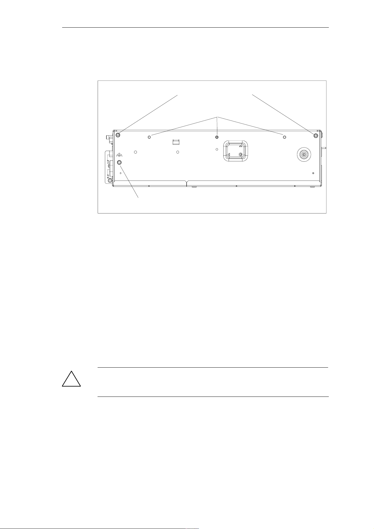
Depending on the configuration of the device, two mounting brackets are included
in the scope of delivery. You can attach these to the housing with 6 screws (M3x6).
M4 thread, max. depth of engagement 5 mm
M3 thread, max. depth of engagement 5 mm
Equipotential grounding connection
Figure 2-1 Screw Connection Points for Mounting Brackets (Cover Side Downwards)
Instructions for wall and ceiling mounting
To install the SIMATIC Box PC 620 in a concrete wall or ceiling proceed as follows:
1. Fix the mounting brackets at the housing of the PC.
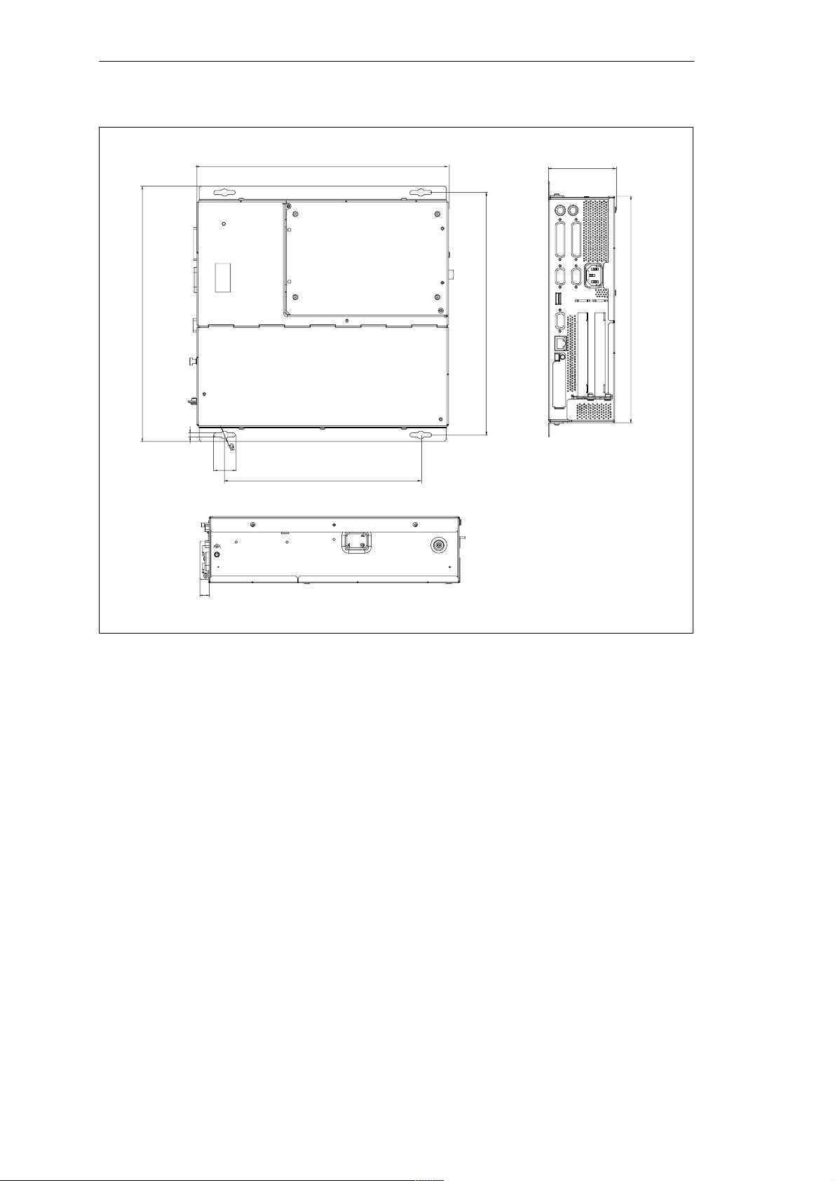
2. Drill four holes of 8 mm diameter and 60 mm depth into the wall or ceiling. You
will find the required dimension drawings on the following pages.
3. Insert the concrete plugs (8 mm diameter and 50 mm long) into the drill holes.
4. Fix the PC with four screws (4 mm diameter and 50 mm long).
In a plasterboard wall or ceiling (min. 13 mm thick), drill holes of 14 mm diameter
and fasten the PC with four anchors (4 mm diameter and 50 mm long).
In a metal sheet wall or eiling (min. 2 mm thick), drill holes of 5 mm diameter and
fasten the PC with four screws (4 mm diameter and min. 15 mm long).
Warnung
!
The installer must verify that the wall or ceiling can support four times the full load
of the SIMATIC Box PC 620 (with mounting brackets and Add-On-Cards).
2-4
SIMATIC Box PC 620 Manual
C79000-G7076-C639-04
Page 19
Commissioning the SIMATIC Box PC 620
301 mm
11.85 “
5 mm
297.2 mm
11.701 ”
286 mm
0.197 “
232 mm
9.134 “
26 mm
1.024 “
79.5 mm
3.13 “
267 mm
11.26 “
10.512 “
11.2 mm
0.441 “
Figure 2-2Dimension Drawings for Fitting in Control Panel with Installation Angle (Device without CD-ROM
Drive)
SIMATIC Box PC 620 Manual
C79000-G7076-C639-04
2-5
Page 20
Commissioning the SIMATIC Box PC 620
301 mm
11.85 “
297.2 mm
11.701 ”
100 mm
3.94 “
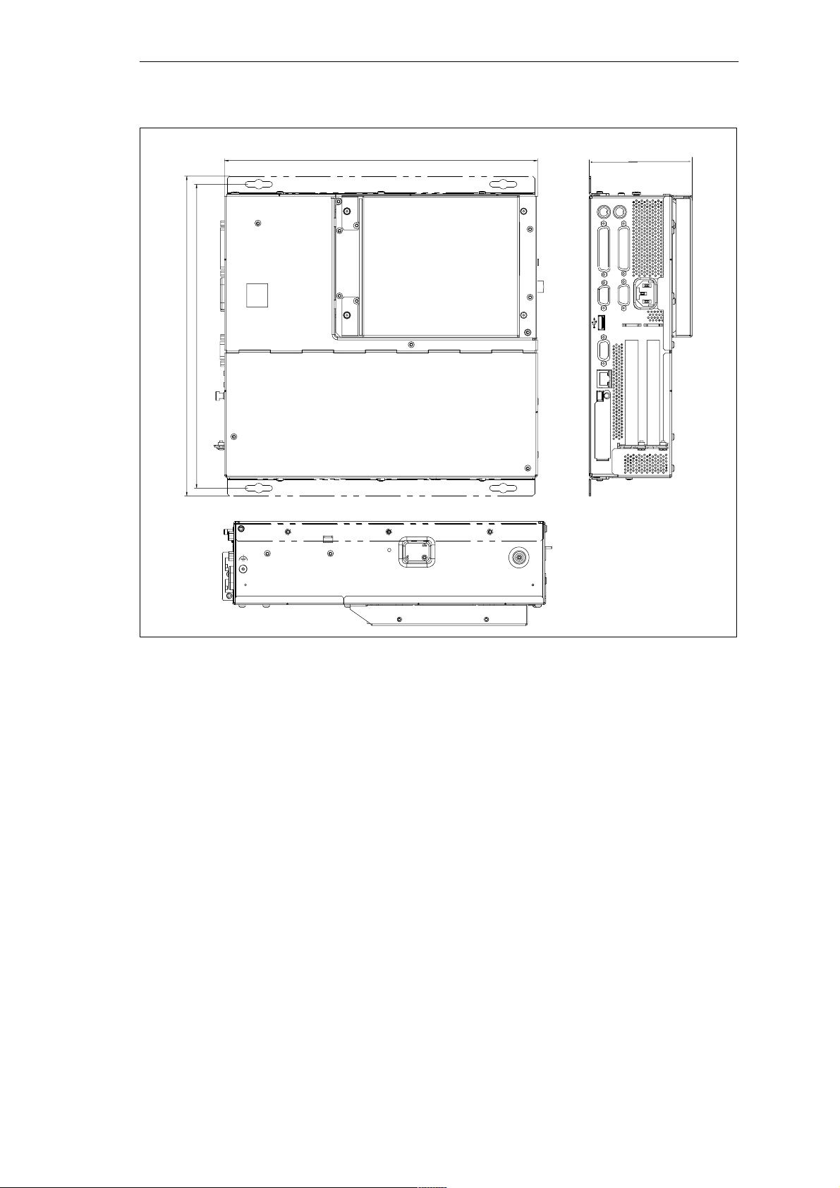
Figure 2-3 Dimension Drawings for Fitting in Control Panel with Installation Angle (Device with CD–ROM
Drive)
2-6
SIMATIC Box PC 620 Manual
C79000-G7076-C639-04
Page 21
Commissioning the SIMATIC Box PC 620
11.2 m m
0.441 “
267.2 mm
10.52 “
79.5 mm
3.13 “
267 mm
10.512 “
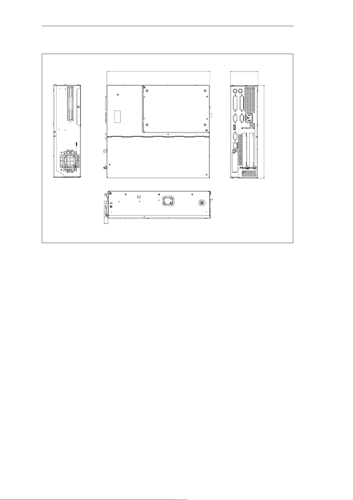
Figure 2-4Dimension Drawings for Fitting in Control Panel without Installation Angle
SIMATIC Box PC 620 Manual
C79000-G7076-C639-04
2-7
Page 22
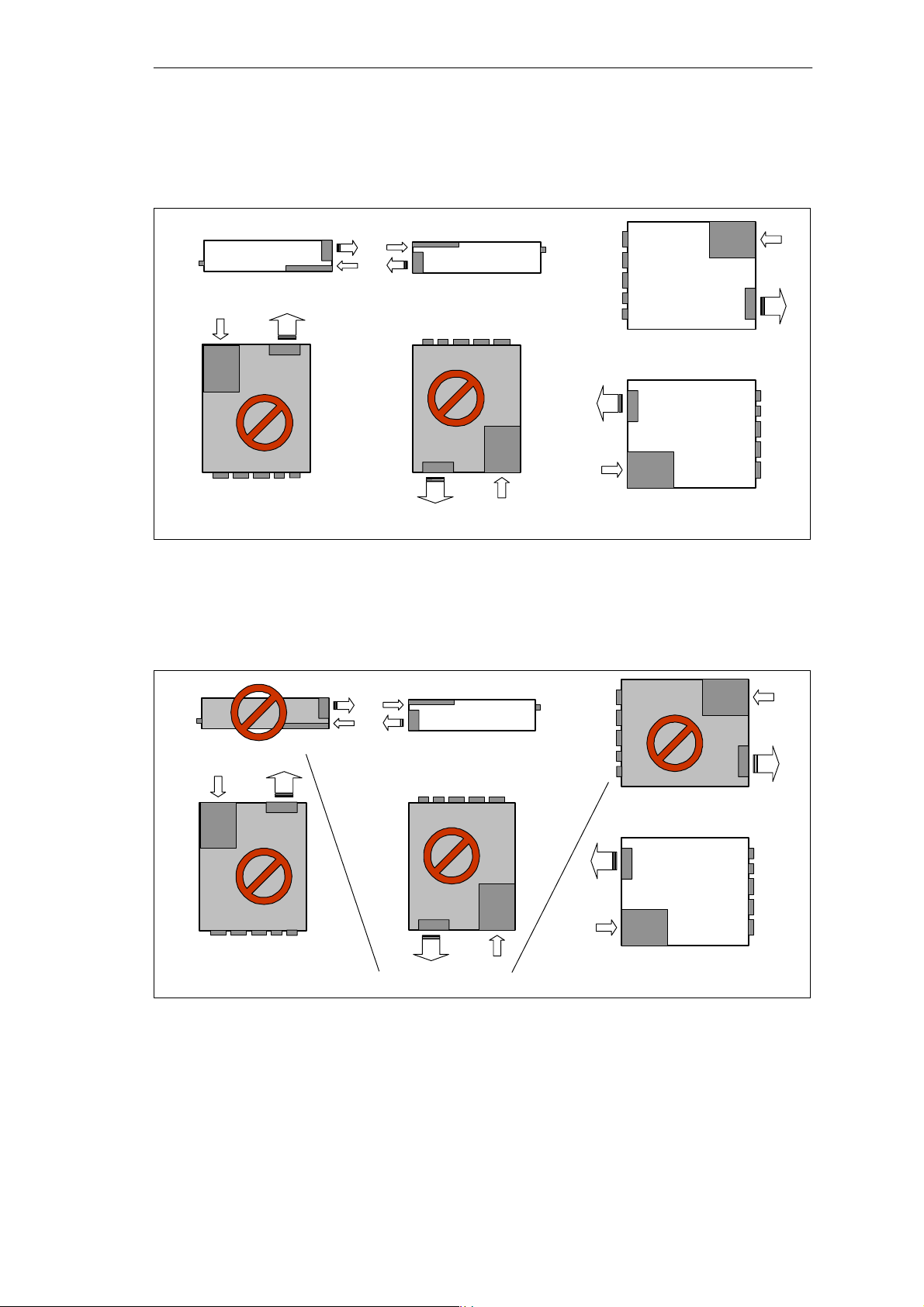
Commissioning the SIMATIC Box PC 620
Permissible Fitting Positions of the PC with Floppy Disk Drive
An inclined position of ± 20 is allowed in each of the permissible fitting positions.
Fan
Ports
FDD
Ports
This fitting position is permissible in devices without an FDD
FDD
Fan
FDD
Fan
Ports
Fan
Ports
FDD
Figure 2-5 Permissible Fitting Positions of the PC with Floppy Disk Drive
Permissible Fitting Positions of the PC with LS120
An inclined position of ±15 is allowed in each of the permissible fitting positions.
FDD
Ports
Fan
Fan
FDD
Preferred position
Ports
Ports
LS120
Ports
LS120
Ports
Fan
Fan
LS120
LS120
Fan
Ports
Fan
These fitting positions are permissible in devices with LS120
Figure 2-6 Permissible Fitting Positions of the PC with LS120
LS120
Ports
Fan
Fan
Ports
LS120
Preferred position
2-8
SIMATIC Box PC 620 Manual
C79000-G7076-C639-04
Page 23

2.3 Preparing for Operation
Connection to the Power Supply Unit
Note
The SIMATIC Box PC 620 is equipped with a safety-tested mains cable and may
only be connected to a grounded grounding outlet.
Make sure that the socket on the device or the grounding outlet of the building
installation is easily accessible and as near as possible to the device.
The SIMATIC Box PC 620 has no mains switch. The mains plug must be pulled
out for complete mains separation. This point must be easily accessible.
If the PC is installed in a cabinet, there must be a central mains disconnector.
Commissioning the SIMATIC Box PC 620
The standard power supply unit of the SIMATIC Box PC 620 is designed for
115/230V systems.
The power supply unit has automatic mains voltage changeover. It is not
necessary to adjust the voltage span.
Equipotential Measures
Low-impedance ground connections ensure that faults arising from external power
supply cables, signalling cables or cables to peripheral units are diverted.
Therefore connect the equipotential grounding connection on the system housing
to the central earth terminal of the cabinet or the unit, into which the computer is
fitted, in such a way that it has low impedance (large surface area, large contacts).
The minimum cross section should not be less than 5 mm2.
The connection is on the side of the device and is identified by the symbol:
SIMATIC Box PC 620 Manual
C79000-G7076-C639-04
2-9
Page 24
Commissioning the SIMATIC Box PC 620
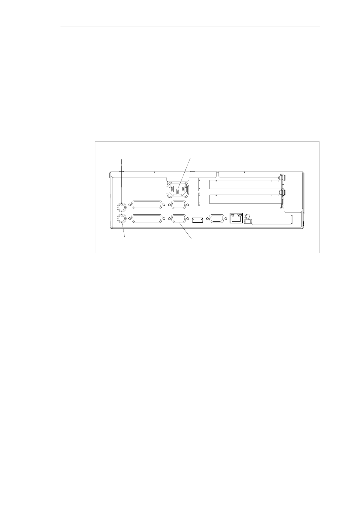
Connecting and Switching on the SIMATIC Box PC 620
Before you connect the SIMATIC Box PC 620 to the mains, the keyboard, mouse
and display or monitor must be connected.
1. Insert the connector cable of these peripheral units into the corresponding
sockets on the port side of the SIMATIC Box PC 620
(see Section 4.2.)
2. Once the peripheral units have been connected, the device is ready for
operation from the power supply. Connect the device to the mains. The
SIMATIC Box PC 620 is now in service.
Device socket for non-heating appliances with AC
PS/2 mouse
supply or terminal screw with DC supply
Keyboard
Figure 2-7 Connecting and Switching on the SIMATIC Box PC 620
VGA port for monitor
Switching off the SIMATIC Box PC 620
The SIMATIC Box PC 620 has no mains switch and is switched off after only
disconnection from the mains.
2-10
SIMATIC Box PC 620 Manual
C79000-G7076-C639-04
Page 25

2.4 Transport
Transporting
Despite the fact that the SIMATIC Box PC 620 is of rugged design, its internal
components are sensitive to severe vibrations or shock. You must therefore protect
the PC from severe mechanical stress when transporting it.
Use the original packing material if you have to ship the SIMATIC Box PC 620
from one location to another.
Caution
!
Risk of damage!
When transporting the PC in cold weather, when it may be submitted to extreme
variations in temperature, make sure that there is no moisture (condensation) on
or in the PC.
Commissioning the SIMATIC Box PC 620
The PC must be allowed to reach room temperature slowly before you switch it on.
If condensation has formed, you should wait approximately 4 hours before switching on the PC.
SIMATIC Box PC 620 Manual
C79000-G7076-C639-04
2-11
Page 26

Commissioning the SIMATIC Box PC 620
2-12
SIMATIC Box PC 620 Manual
C79000-G7076-C639-04
Page 27

Welcome to the SIMATIC Box PC 620
Overview of Chapter
In chapter you will find on page
3.1 Right-Hand Side of the Device (Port Side) 3-2
3.2 Left-Hand Side of the Device (Drive Side) 3-4
3.3 Ports 3-5
3.4 PC Card Port 3-7
3.5 Drives 3-9
3.6 Backup Battery 3-14
3
SIMATIC Box PC 620 Manual
C79000-G7076-C639-04
3-1
Page 28
Welcome to the SIMATIC Box PC 620
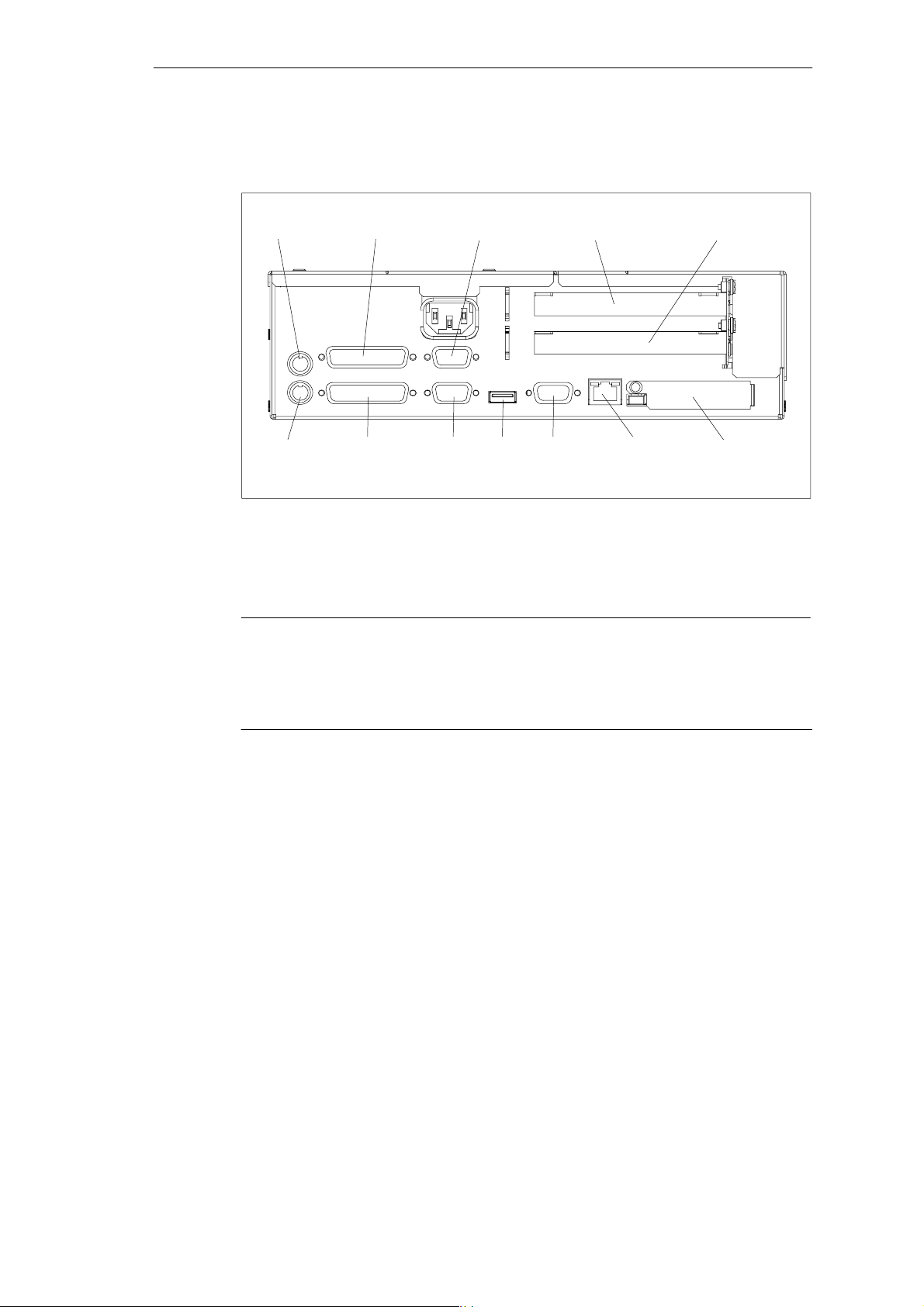
3.1 Right-Hand Side of the Device (Port Side)
1
Mouse COM1/V24/AG COM2 PCI-Slot PCI/ISA-Slot
*
2
*
PC-CardKeyboard EthernetMPI/DPUSBVGALPT1/Printer
Figure 3-1 Right-Hand Side of the Device with Ports
*1Without TTY for the basic variant of the Box PC
*2Not available for the basic variant of the Box PC
Note
Ensure that you use shielded cables and metal plugs to connect the peripheral
units; if this is not done, the approval for operation will be invalid! Screw down the
plugs of the interface cables to the PC housing by means of a screwdriver. You
thereby improve the electrical shielding.
3-2
SIMATIC Box PC 620 Manual
C79000-G7076-C639-04
Page 29

Welcome to the SIMATIC Box PC 620
Connections Function
VGA VGA port for connecting an external monitor, 15 pins,
subminiature Cannon connector, sockets
COM1/V24/AG *
COM2 Serial port 2 (V24) 9 pins, subminiature Cannon connector, pins
Mouse PS/2 mouse connector
Keyboard *
LPT1/Printer Parallel port, connection for devices with parallel interface (e.g.
MPI/DP
(RS 485) *
Ethernet Connection for local network (LAN), RJ45
USB Connection for Universal Serial Bus
PC-Card Connection for PC cards Type I/II/III
PCI slot Internal slot for expansion modules
PCI/ISA slot Internal slot for expansion modules
Device socket for
non-heating
appliances with AC
supply or terminal
screw with DC supply
3
1
2
Serial port 1 (V24, via BIOS-Setup can be switched to TTY)
25pin), 25 pins, subminiature Cannon
connector, sockets
PS/2 keyboard connection
printer), 25 pins, subminiature Cannon connector, sockets
Multi-Point interface / Profibus DP connection
Connection of an S7 programmable controller, 9 pins,
subminiature Cannon connector, socket
Power suppply
If expansion modules have been inserted in the PC, there are additional ports.
Please refer to the description of the respective module for their purpose.
*1Keyboards with an integrated track ball (e.g. PG 720 or PG 740) can be
connected.
*2Electrical isolation through an extra-low voltage safety circuit (SELV).
MPI/DP is not available for the basic variant of the Box PC.
*3You change the connection into a male connector by attaching the gender
changer (constituent part of the source material package.
Without TTY for the basic variant of the Box PC.
SIMATIC Box PC 620 Manual
C79000-G7076-C639-04
3-3
Page 30
Welcome to the SIMATIC Box PC 620
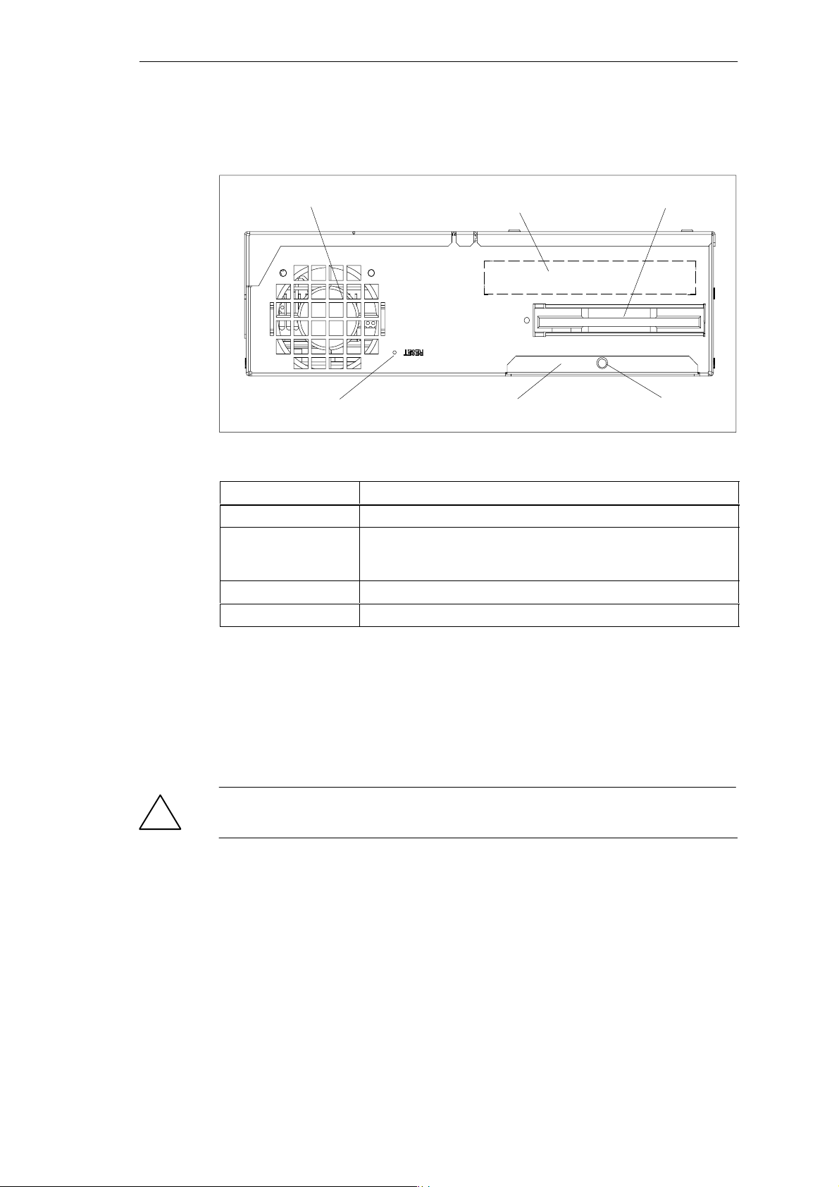
3.2 Left-Hand Side of the Device (Drive Side)
Fan
Reset Button
Figure 3-2 Left-hand Side of the device
Connections Function
Fan Cooling
Floppy disk drive with
ejector
(LS120 as an option)
Front ports Connection of front elements
Reset button Reset of the SIMATIC Box PC 620 (cold start)
Use of 3,5” diskettes
Name plate
Cover for front ports
Floppy disk drive
Plastic rivet
Reset Button
The reset button can be actuated with a pointed object (e.g. an opened up paper
clip).
If you actuate, the button, a hardware reset is triggered. The PC restarts.
Caution
!
Data loss is possible with a hardware reset.
3-4
SIMATIC Box PC 620 Manual
C79000-G7076-C639-04
Page 31

3.3 Ports
Front Ports
The front ports are located behind the cover below the floppy disk drive. They are
used for connection of the following front elements:
I/O port for the connection of front components
LVDS display port
CMOS display port
The front ports can be accessed as follows:
1. Undo the plastic rivet on the cover below the floppy disk drive with a flat
screwdriver.
2. Pull the cover out of the guide. The front ports are now accessible.
The CMOS display port is only accessible after removal of the floppy disk drive.
Welcome to the SIMATIC Box PC 620
VGA Port
Note
Keep the cover and the plastic rivet for reuse.
Please read the following note referring to the operation of a flat display and an
external monitor:
Hinweis
The default setting of the display provides the simultaneous operation of a flat display
and an external monitor. If no front display element is connected, the display is
effected on the external monitor with a resolution of 640 x 480 pixels. Modes with a
lower resolution and text modes are expanded to this format.
To optimize the screen display for an external monitor, select ”Hardware Options”
under Setup in the main menu and set ”CRT/LCD selection: CRT enabled”. A
resolution of 1024 x 768 pixels with a higher refresh rate is then possible.
SIMATIC Box PC 620 Manual
C79000-G7076-C639-04
3-5
Page 32
Welcome to the SIMATIC Box PC 620
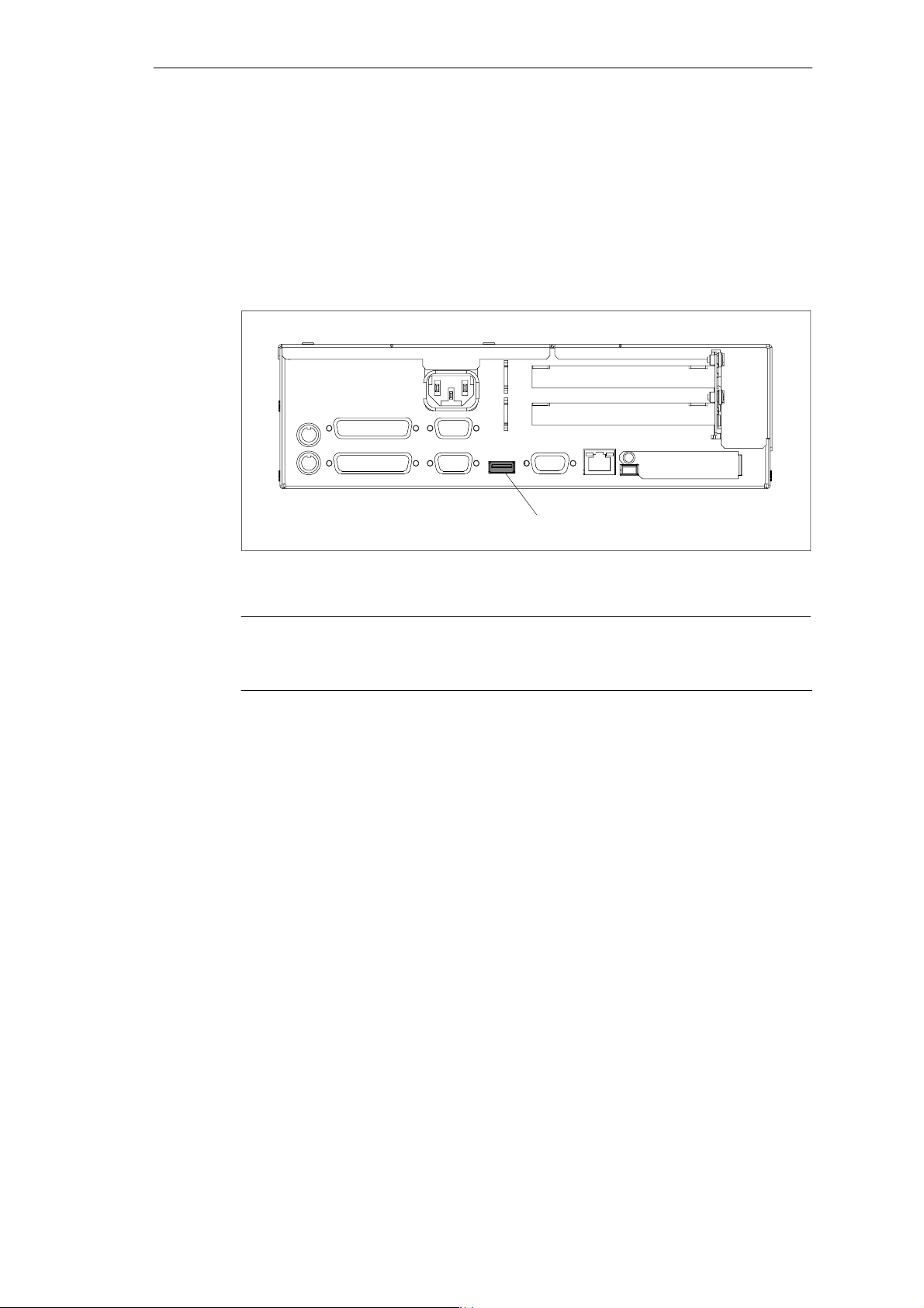
Connecting USB Devices
You can connect peripheral devices with USB interfaces to the USB port.
Plug the USB cable into the port
The device connected in this way is available as soon as it has been registered
by the Plug and Play operating system (e.g. Windows 98).
A USB keyboard can be used to manipulate the Bios setup.
USB port
Figure 3-3 Connection of USB Devices
Note
Operating systems which do not support Plug and Play (e.g. Windows NT 4.0) do
not generally allow the operation of USB devices.
3-6
SIMATIC Box PC 620 Manual
C79000-G7076-C639-04
Page 33
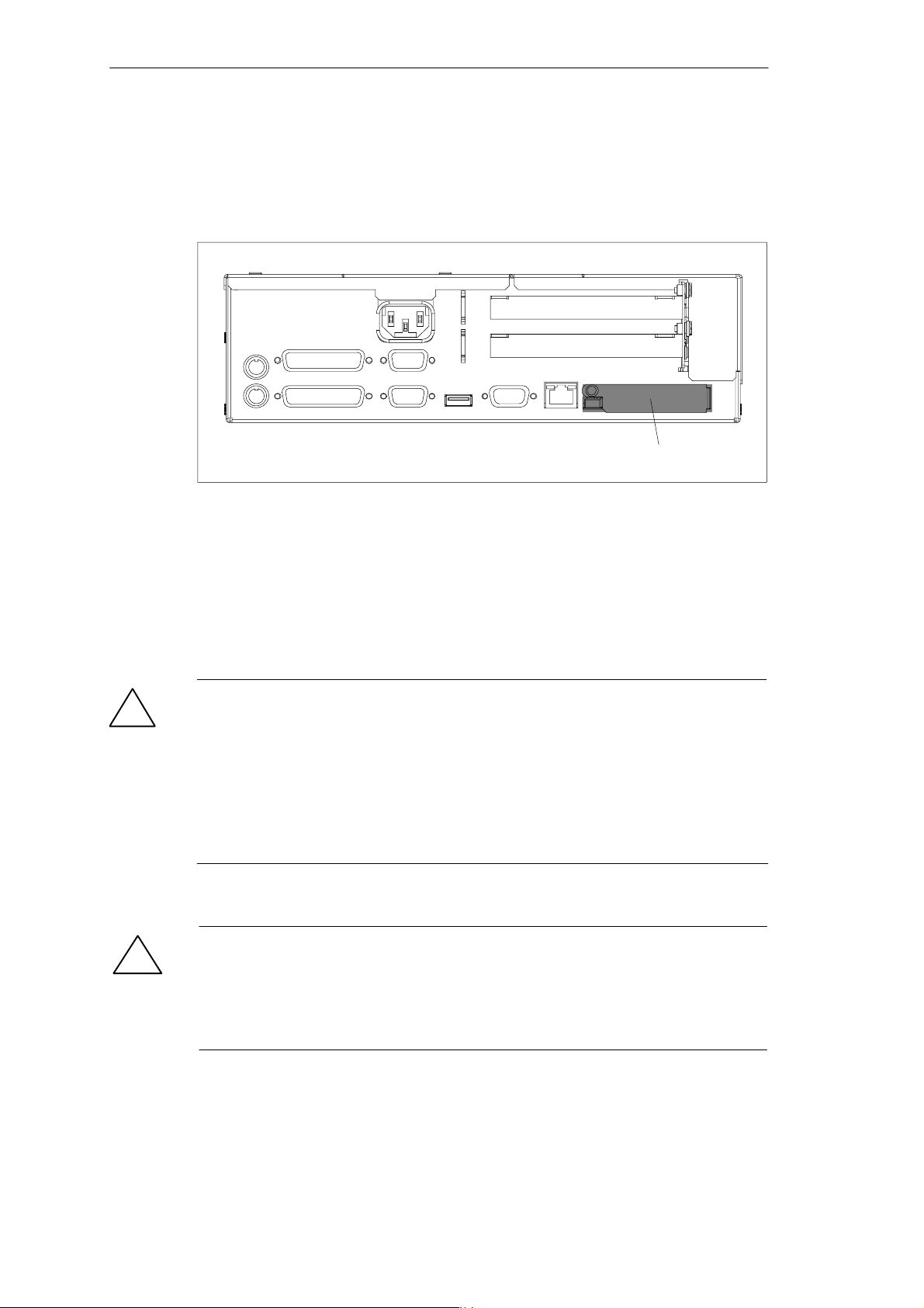
3.4 PC Card Port
Cardbus cards and PCMCIA cards can be operated through the PC card port of
the SIMATIC Box PC 620.
Figure 3-4 PC Card Port
Welcome to the SIMATIC Box PC 620
PC card port
The following is to be observed when working with cardbus/PC cards:
1. Open the port cover on the left–hand side of the device by undoing the plastic
rivet with a flat screwdriver.
2. Pull the cover out of the guide.
3. Insert the desired PCMCIA card or cardbus card.
Caution
!
!
Before inserting PC Cards please make sure that the PC Card Ejector is
completely pressed otherwise the cards e.g. Flash Memory Cards could get stuck
in the slot. The PC Cards cannot be inserted correctly.
Always insert the PC card with the label toward the rear of the programming
device.
Do not remove the PC card while data transfer is in progress (risk of data loss and
system crash).
Caution
Always discharge your body’s charge of static electricity by briefly touching a
grounded object before inserting or removing a PC card (see ESD Guideline in
Section A.1 or electronic manual).
Otherwise damage could occur.
SIMATIC Box PC 620 Manual
C79000-G7076-C639-04
3-7
Page 34

Welcome to the SIMATIC Box PC 620
Note
Peak currents of 650 mA at 5 V based on 3 s are permitted!
Examples of PCMCIA cards connected to PC card interface for
Installing PC Cards
Note the following when installing these cards:
Note
Depending on the configuration of the SIMATIC Box PC 620, there may not be any
free interrupts available for operating PC Cards. You have to reserve the necessary
PC card interrupts in the BIOPS setup menu as follows:
Set the necessary interrupt via Advanced > PCI-Configuration >
PCI/PNP ISA IRQ Resource Exclusion to “reserved” (default: available).
Hard Disk 330 mA read/write
(Maxtor MXL-131-III) 640 mA spin up 2 s. . . . . . . .
110 mA idle. . . . . . . . . . . . . . . . . . . . . . . . . .
Fax/modem 60 mA idle. . . . . . . . . . . . . . . .
(Dr. Neuhaus) 140 mA transfer. . . . . . . . . . . . . .
Ethernet
(XIRCOM) 150 mA. . . . . . . . . . . . . . . . .
3-8
SIMATIC Box PC 620 Manual
C79000-G7076-C639-04
Page 35
Welcome to the SIMATIC Box PC 620
3.5 Drives
The SIMATIC Box PC 620 is equipped as standard with a 3.5” disk drive or an
LS120 drive and a 3.5” hard disk drive.
3.5.1 Disk Drive (Depending on the Device Configuration)
You can store programs and data on diskettes with the disk drive and load them
from diskettes into the SIMATIC Box PC 620.
Types of Diskette
You can use following diskettes:
Double Sided High Density Diskette Double Sided Double Density Diskette
3.5 in. 3.5 in.
1.44 Mbytes (135 TPI) 720 Kbytes
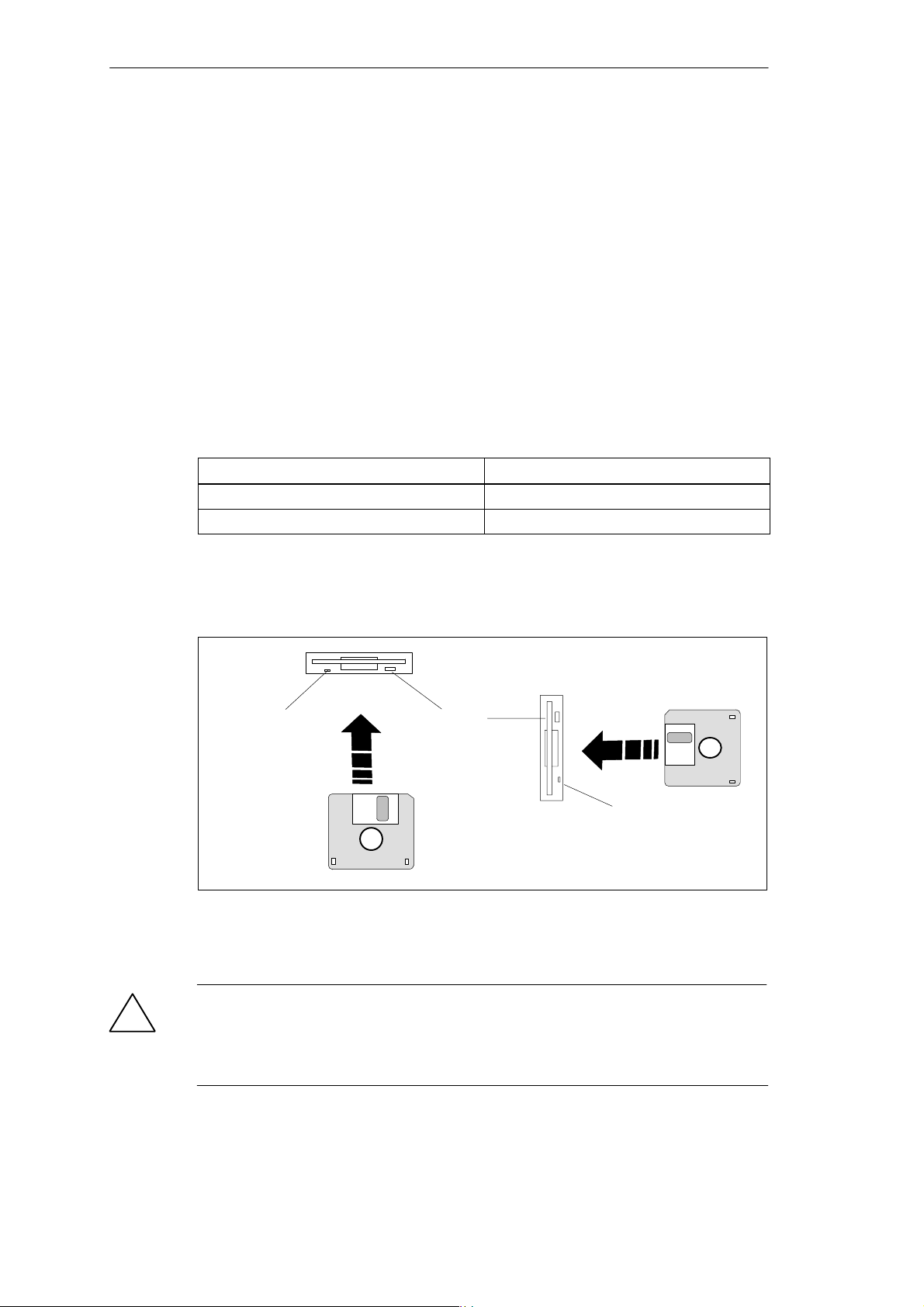
Handling Diskettes with the Floppy Disk Drive
The diskette is inserted in the disk drive as shown below:
Access LED
Figure 3-5 Handling Disks
When the floppy disk drive is being accessed, the access indicator light is lit.
Caution
!
Risk of loss of data!
Ejector
Access LED
When the green access LED of the floppy disk drive is lit, the ejector may not be
actuated.
SIMATIC Box PC 620 Manual
C79000-G7076-C639-04
3-9
Page 36
Welcome to the SIMATIC Box PC 620
3.5.2 LS 120 Drive (Depending on Device Configuration)
The SIMATIC Box PC 620 can be equipped with an LS 120 drive as an alternative
to a floppy disk drive.
Larger volumes of data can be stored on LS 120 data carriers than on a
1.44 MB floppy disk drive. The LS 120 has the following features:
– The LS 120 is compatible with a 1.44 MB floppy disk drive,
i.e. 1.44 MByte disks can also be processed.
– An LS 120 data carrier has a maximum data volume of 120 MBytes.
– The LS 120 is connected via an ATAPI (IDE) port.
Handling Disks with the LS 120 Drive
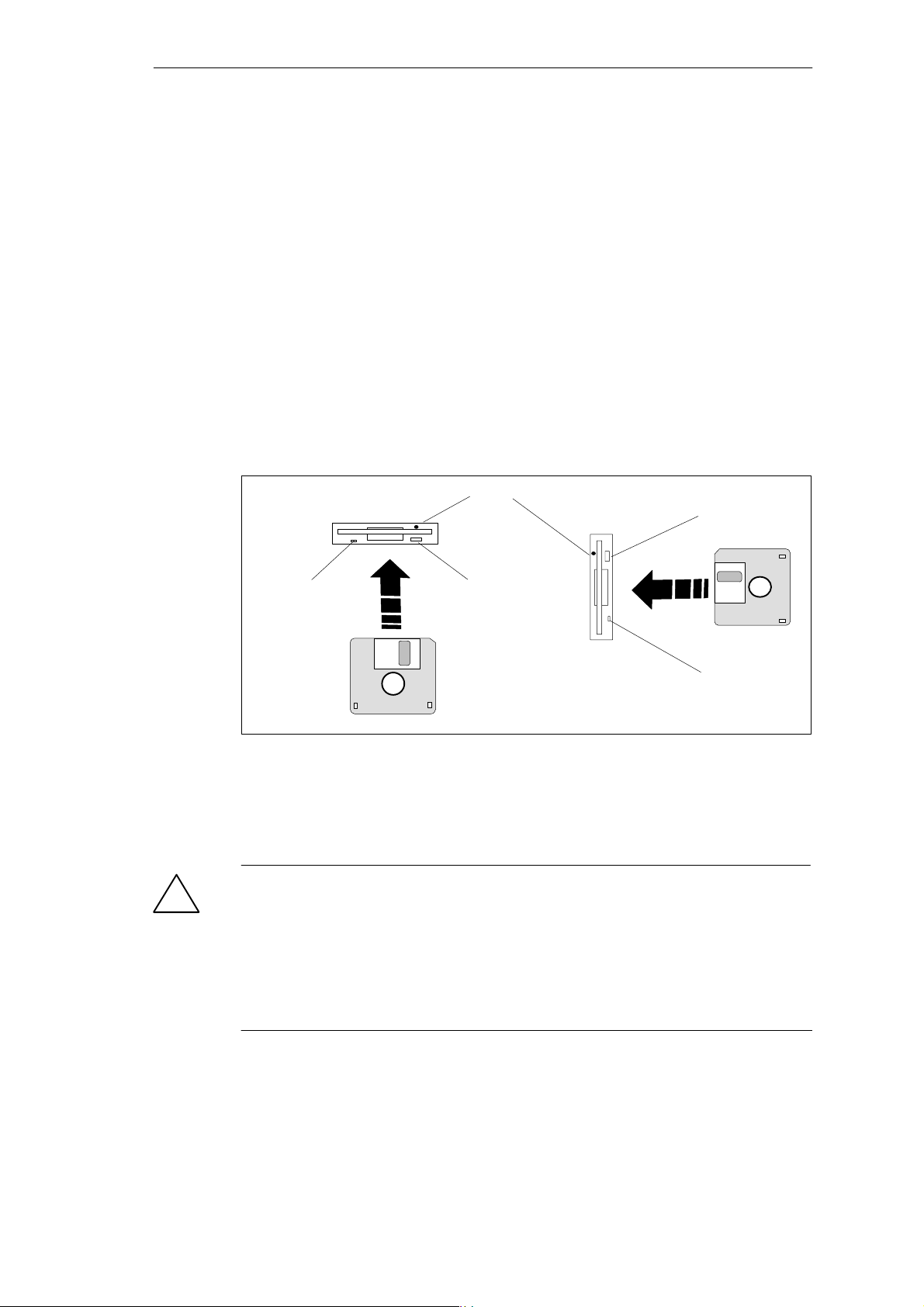
Depending on the fitting position, the disks are inserted into the disk drive as illustrated below:
Access hole for emergency ejection (only LS120)
Ejector
Access LED
Figure 3-6 Handling Disks
Ejector
Access LED
When the LS 120 drive is being accessed, the access indicator light is lit.
Emergency ejection is carried out in the same way with the LS120 as in the
CD-ROM drive. See Section 3.4.4. for details.
Caution
!
Risk of loss of data!
When the green access LED of the LS 120 drive is lit, the ejector may not be
actuated.
LS 120 drives are very sensitive to shocks of a non-permissible level. Shocks
during operation can lead to damage to the drive or the data carrier. You can find
the permissible values in the technical data in Section 7.1.
3-10
SIMATIC Box PC 620 Manual
C79000-G7076-C639-04
Page 37

Welcome to the SIMATIC Box PC 620
3.5.3 Hard Disk Drive
The hard disk drive is used for the storage of large quantities of data. it is fitted in a
mounting which is easily exchangeable and damped against vibration.
Caution
!
Risk of loss of data and damage to the drive!!
Drives are sensitive to vibrations and shock. Any vibrations occurring during
operation can lead to the loss of data or damage to the drive.
If you intend transporting the unit, switch it off, and wait until the drive has come to
rest (about 20 seconds) before you move it.
3.5.4 CD-ROM Drive (Depending on the Device Equipment)
Depending on the device equipment, a CD-ROM drive is fitted in the
SIMATIC Box PC 620. The fitting depth of the PC is increased by 20 mm as a result. The CD-ROM drive allows you to read CDs.
Opening the Drawer
By briefly pressing the eject button, the drawer springs out slightly. Now pull the
drawer out until it clicks into position.
Inserting / Removing CDs
Now insert the CD in the drawer with the labeling face up, and press it firmly down
into the center of the turntable. To remove the CD, hold it by the edges and pull
upwards.
Caution
!
To avoid too much pressure on the open drawer, always hold the drawer at the
front with one hand when inserting or removing a CD.
SIMATIC Box PC 620 Manual
C79000-G7076-C639-04
3-11
Page 38

Welcome to the SIMATIC Box PC 620
Closing the Drawer
Push in the drawer until it closes completely. Do not press the eject button.
Note
The EJECT function offered by various applications for opening the CD ROM
drawer does not work with this drive.
After the drawer has been closed, the CD is tested and the access display light on
the drive starts to flash:
– If the display flashes continually, the CD is faulty but can still be read,
– If the display flashes several times and then remains lit, the CD you have
inserted is defective and cannot be read.
3-12
SIMATIC Box PC 620 Manual
C79000-G7076-C639-04
Page 39
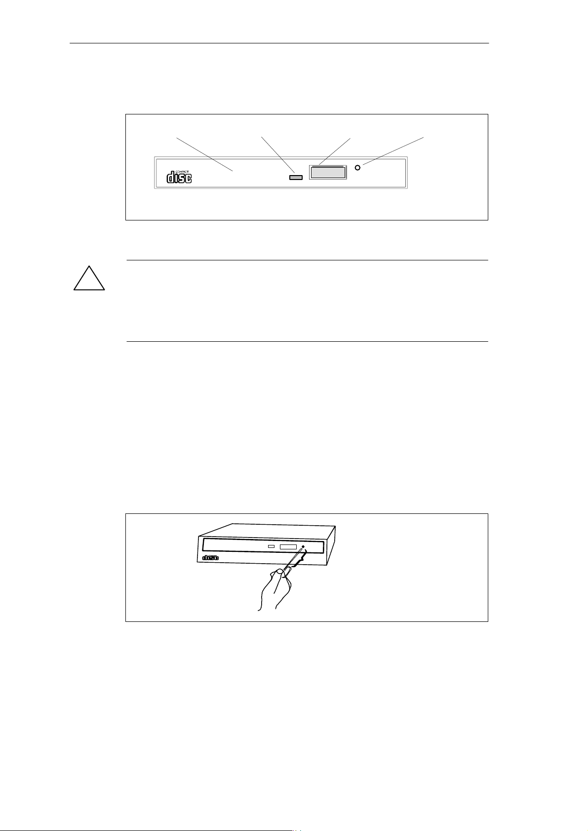
CD-ROM Front
Figure 3-7 CD-ROM Front
Caution
!
Risk of data loss and damage to the drive!
CD-ROM drives are sensitive to vibrations and shock. Any vibrations occuring
during operation can lead to damage to the drive or CD. You can find the
permissible values in the technical data in Chapter 7 of the operating manual.
Welcome to the SIMATIC Box PC 620
Emergency ejectDrawer Eject buttonAccess LED
Emergency Eject
The procedure described below can used to remove a disc from the CD ROM reader if the Open/Close button is disabled by software or a power failure occurs. In
this case the CD tray cannot be opened automatically.
1. Turn off the power to the CD ROM reader (switch off your device if necessary).
2. Insert a steel rod or a stiff paper clip (with a maximum diameter of 1.3 mm and a
mimimum of 55mm) into the emergency eject hole at the front of the drive and push
lightly. The CD tray is ejected by about 10 mm. Pull it all the way open by hand and
lift the disc out carefully.
Figure 3-8Emergency Ejection
at least 55 mm (2.1654”) in length
SIMATIC Box PC 620 Manual
C79000-G7076-C639-04
3-13
Page 40

Welcome to the SIMATIC Box PC 620
3.6 Backup Battery
A backup battery (3.6 V lithium battery) powers the hardware clock even after the
programming device is switched off.
There is a battery on the motherboard in this device. Batteries may only be
exchanged by technical personnel. Note the information in the documentation of
the CPU module! Observe the local regulations on the disposal of special waste
when disposing of dead batteries.
Caution
!
There is the danger of an explosion if the battery is not exchanged as directed.
Replace only with the same type or an equivalent type recommended by the
manufacturer. Dispose of used batteries in accordance with the manufacturer’s
instructions.
Warning
!
Risk of severe personal injury or property damage, danger of release of harmful
substances.
There may be a danger of explosion if the battery is not handled properly.
Incorrect disposal of used batteries can cause the release of harmful substances.
Do not throw a new or discharged lithium battery into an open fire, do not solder
onto the cell container. Do not recharge the battery, do not open the battery by
force.
The correct lithium battery is available from Siemens (order no.: W79084-E1003-B1).
Return used batteries to the manufacturer/recycler or dispose of them according to
local regulations.
3-14
SIMATIC Box PC 620 Manual
C79000-G7076-C639-04
Page 41

Setting Up and Operating the SIMATIC Box PC 620
Chapter Overview
In chapter you will find on page
4.1 Connecting the SIMATIC Box PC 620 to the Power Supply 4-2
4.2 Connecting Peripheral Units 4-5
4.3 Working with PC Cards 4-10
4.4 Connecting the SIMATIC Box PC 620 to other SIMATIC S5 Units 4-13
4.5 Connecting the SIMATIC Box PC 620 to a SIMATIC S7 Network
(MPI/DP)
4.6 Networking the SIMATIC Box PC 620 with Other Stations on
PROFIBUS
4.7 Networking the SIMATIC Box PC 620 and Other Computers on
Industrial Ethernet
4.8 Connection under Windows 4-21
4
4-18
4-20
4-21
SIMATIC Box PC 620 Manual
C79000-G7076-C639-04
4-1
Page 42
Setting Up and Operating the SIMATIC Box PC 620
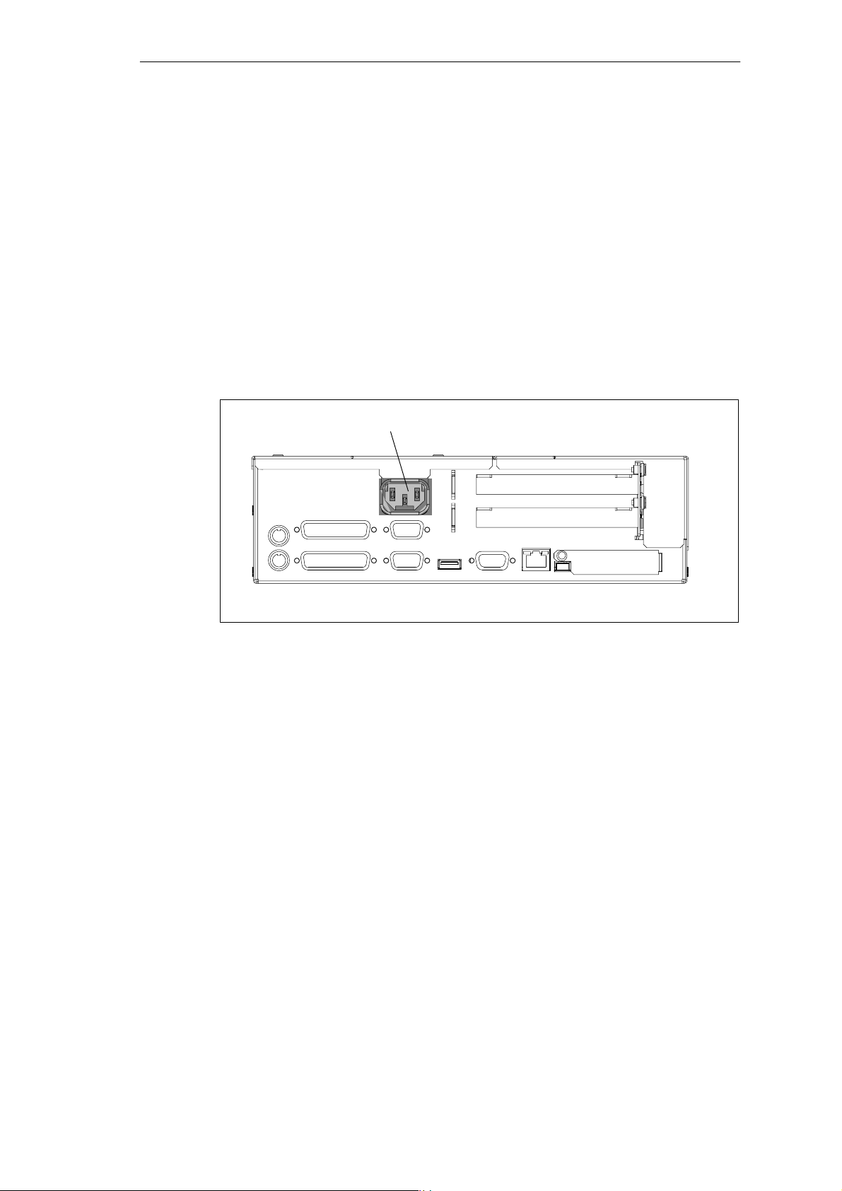
4.1 Connecting the SIMATIC Box PC 620 to the Power Supply
Connecting to the Power Supply
You can operate the SIMATIC Bo x PC 620 on 120 V and 230 V power systems
using the external power supply unit. The voltage is selected automatically.
1. Plug the power supply cable supplied into the inlet connector for non-heating
appliances
2. Connect the power cable to a socket outlet with a grounded protective
conductor.
3. The device is now ready for power supply operation and the battery will be
charged if required.
Connection to power supply
Inlet connector for non-
heating appliances
Figure 4-1 Connection to Power Supply (Inlet Connector for Non-Heating Appliances)
4-2
SIMATIC Box PC 620 Manual
C79000-G7076-C639-04
Page 43

Power Connection
The device is intended for poeration in grounded electricity supply systems
(TN systems to VDE 0100 part 300 or IEC 364-3).
Service in non-grounded or impedance-grounded supply systems (IT systems) is
not intended.
The power line should meet the respective local safety requirements.
Check whether the device’s set supply voltage is the same as the local supply
voltage.
This device is equipped with a safety-tested power supply cable. You may connect
this device only to a grounding outlet with a grounding contact.
Make certain that the socket outlet on the device or the grounding contact for the
building wiring system is freely accessible and as near to the device as possible.
The mains switch does not separate the device from the power system. To
establish a complete power separation, you must disconnect the power plug (inlet
connector on the back of the device). This location must be accessible. A central
isolating switch must be present for cabinet mounting.
Setting Up and Operating the SIMATIC Box PC 620
Install the cables so that no one can step on them or trip over them. When you
connect the device, adhere to the relevant instructions in Chapter 2 of this manual.
Do not connect or disconnect power supply cables and data transmission lines
during thunderstorms.
In emergency situations (for example, damaged housing, damaged operator
elements, a damaged power supply cable, ingress of liquids or foreign particles),
switch off the device. Disconnect the power plug and inform the responsible
service personnel.
The SIMATIC Box PC 620 must be switched off when you connect or disconnect
I/O devices (keyboard, mouse, printer, etc.). You can damage the PC if you do not
adhere to these instructions.
When plugging in/unplugging peripheral connections (keyboard, mouse, printer
etc.) the SIMATIC box PC 620 must be switched off (not for PC-Card and USBdevices). In the case of non-observance, this can lead to damage to the PC.
SIMATIC Box PC 620 Manual
C79000-G7076-C639-04
4-3
Page 44

Setting Up and Operating the SIMATIC Box PC 620
Country-Specific Information
For the United States and Canada:
In the United States and Canada USA, a CSA or UL-listed power supply cable
must be used.
The male plug is a 5-15 style.
For Operation with 120 V:
Use a UL Listed, CSA Labelles Cord Set, consisting of a min. 18 AWG. Type SVT
or STJ three conductor flexible cord, max. 4.5 m (15 feet) in length and a parallel
blade grounding type attachment plug rated 15 A, min 125 V.
For Operation with 240 V:
Use a UL Listed, CSA Labelled Cord Set, consisting od a min. 18 AWG. Type SVT
or SJT three conductor flexible cord, max. 4.5 m (15 feet) in length and a tandem
blade grounding type attachment plug, rated 15 A, 250 V.
For Operation with 230 V (outside of USA and Canada)
Use a Cord Set consisting of a min 18 AWG cord and grounding type attachment
plug rated 15 A, 250 V. The cord set should have the approviate safety approvals
for the country in which the equipment will be installed and marked.
4-4
SIMATIC Box PC 620 Manual
C79000-G7076-C639-04
Page 45
Setting Up and Operating the SIMATIC Box PC 620
4.2 Connecting Peripheral Devices
Note
When connecting peripheral units, ensure that the components have industrial
capability
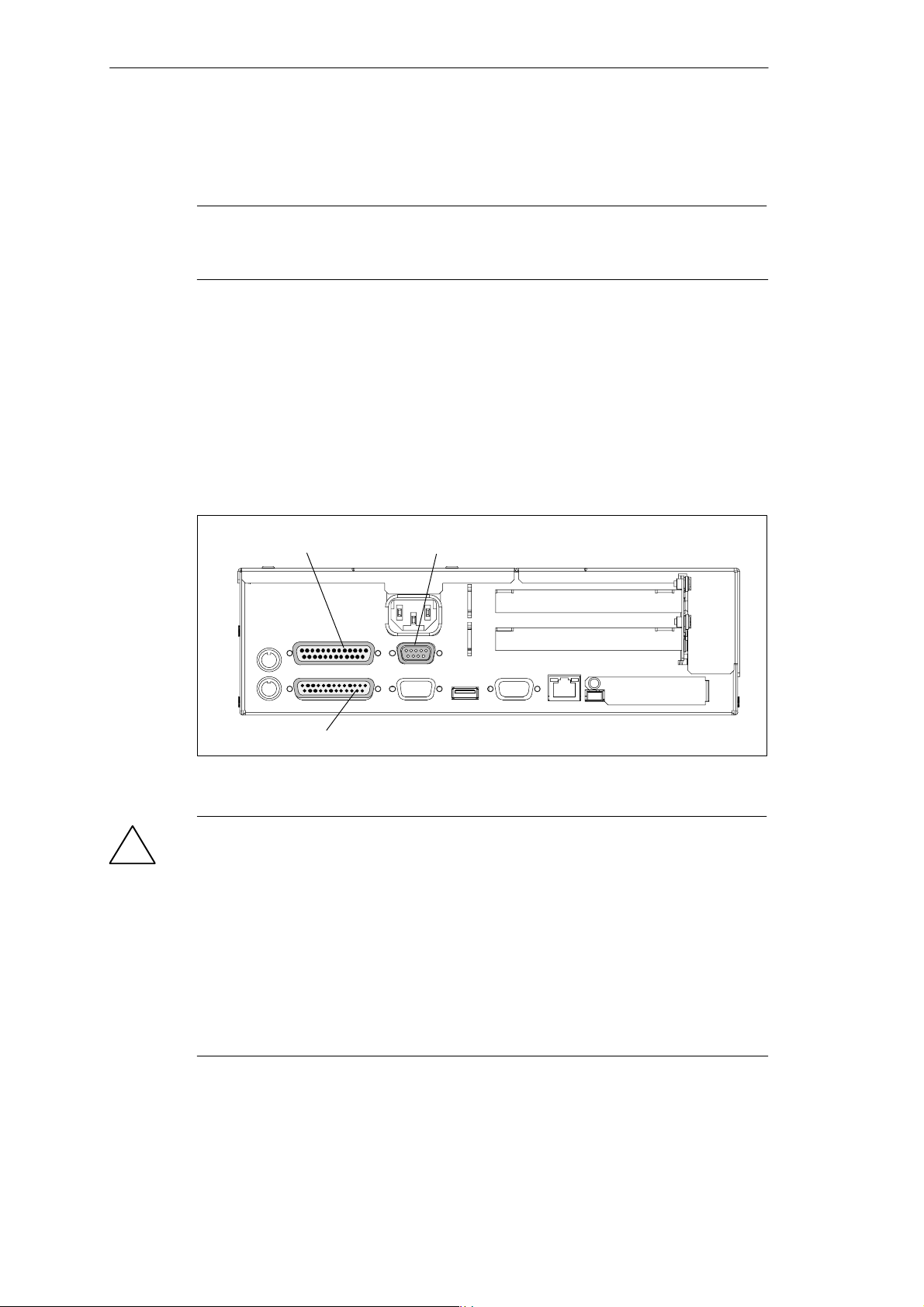
Connecting the Printer to the Parallel Port
Proceed as follows to connect your printer:
1. Switch off the SIMATIC Box PC 620 and the printer.
2. Plug the printer cable into the LPT1 parallel port.
3. Connect the printer cable to the printer.
4. Screw the connector tight at the interface port.
COM 1 COM 2
socket (parallel) port (serial)
LPT 1
socket (parallel)
Figure 4-2 Position of the Printer Ports
Caution
!
Risk of damage to the unit!
Switch the unit off before connecting the parallel printer to the LPT 1 port (the
printer should also be switched off).
Make sure that you use the correct port. If you use the wrong port or wrong
connecting cables, the port may be damaged.
Before plugging in the cables, the electrostatic charge of your body, the unit, and
the cables must be equalized. To do this, touch the mounting plate for the ports on
the left-hand side of the unit.
Only use original connecting cables.
SIMATIC Box PC 620 Manual
C79000-G7076-C639-04
4-5
Page 46
Setting Up and Operating the SIMATIC Box PC 620
Connecting the Printer to the Serial Port
You can also connect your printer to the SIMATIC Box PC using a serial COM port.
You will find information on how to adapt and set your interface and which connecting cable you require in the description of your printer.
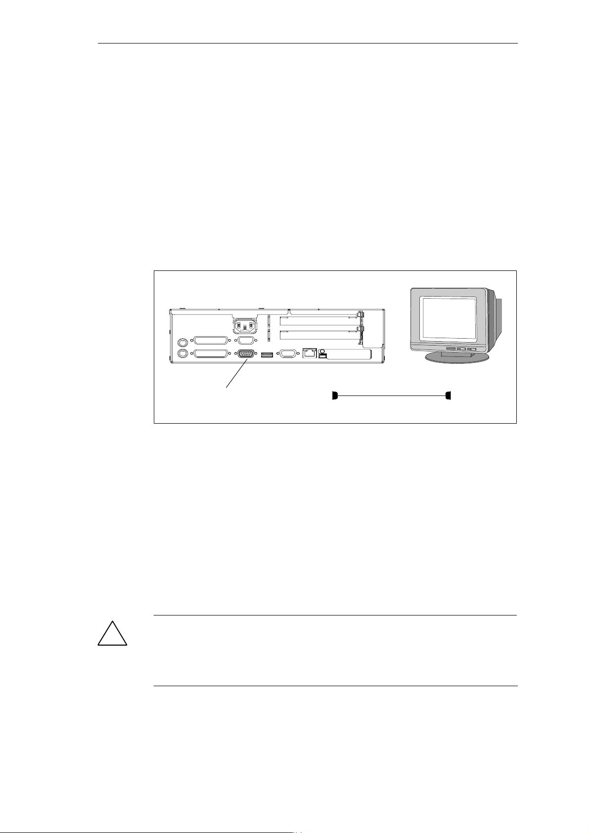
Connecting Monitors
You connect external multisynchronous monitors using the standard
VGA connector on the left-hand panel side of the unit. We recommend that you
use a Siemens monitor.
You must switch the SIMATIC Box PC off before connecting the monitor cable. You
will find further information about the connector pinout in Chapter 8.
VGA-Socket
Figure 4-3 Connecting the Monitor
Proceed as follows to connect your monitor:
1. Switch the SIMATIC Box PC 620 and the monitor off.
2. Insert the monitor lead in the VGA socket.
3. Screw down the plug.
4. Connect the monitor cable to the monitor.
5. Switch the PC and the monitor on.
6. Make the necessary changes in the SETUP program
(Menu > Main > Hardware Options “CRT enabled”, “LCD enabled”
“SIMULTAN”)”.
Caution
!
Danger of damaging the monitor!
If you want to set higher clock frequencies and resolutions, first make sure that the
monitor you are using is suitable for a higher clock frequency and resolution.
If the clock frequency is too high, this can cause damage to the monitor.
4-6
SIMATIC Box PC 620 Manual
C79000-G7076-C639-04
Page 47
Using a Mouse
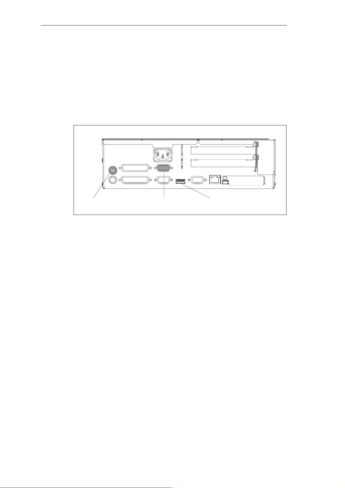
You can connect both a PS/2-USB and a serial mouse to the
SIMATI C Box PC 620.
Connecting a PS/2 Mouse
You can connect an external PS/2 mouse or another external pointing device to an
additional PS/2-compatible mouse connector.
Setting Up and Operating the SIMATIC Box PC 620
Port for PS/2 mouse
(socket)
Figure 4-4 Connecting the Mouse
To connect the mouse, proceed as follows:
1. Switch off your PC.
2. Plug the cable of the PS/2 mouse or another external pointing device into the
mouse connector.
3. Switch on your PC again.
Connecting a Serial Mouse
You can connect a serial mouse to the COM2 serial port. To operate a serial
mouse, the appropriate mouse driver must be initialized and assigned parameters.
You will find the information you need to do this in the description of your mouse or
in the description of the operating system.
1. Switch off your PC.
2. Plug the serial mouse into the mouse connector labeled COM2.
3. Secure the connector with the screws.
4. Switch on your PC again.
COM 2
Port for serial mouse
(connector)
USB connection for
USB mouse (socket)
You can find out how to connect a USB mouse in “Connecting USB devices”.
SIMATIC Box PC 620 Manual
C79000-G7076-C639-04
4-7
Page 48
Setting Up and Operating the SIMATIC Box PC 620
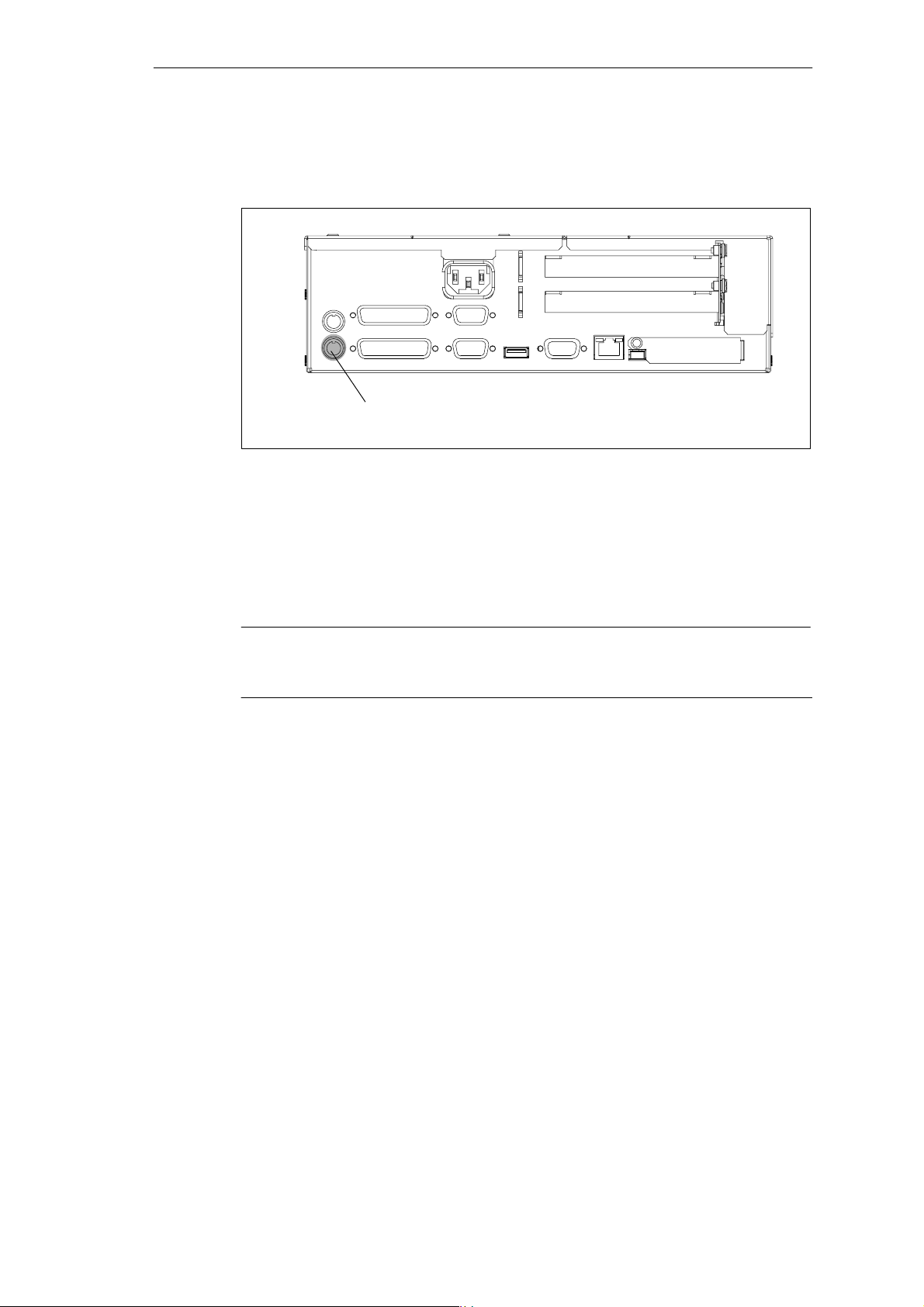
Connecting a PS/2 Keyboard
A PS/2 keyboard of your choice can be connected to the SIMATIC Box PC 620.
PS/2 keyboard connection
Figure 4-5 Connecting a PS/2 Keyboard
To connect the keyboard, proceed as follows:
1. Switch off your device.
2. Insert the plug of the PS/2 keyboard.
3. Re-start your device.
Note
It is recommended that a keyboard with straight keyboard connector is used, so
that the connector does not obscure adjacent ports.
4-8
SIMATIC Box PC 620 Manual
C79000-G7076-C639-04
Page 49
Connecting USB Periphery
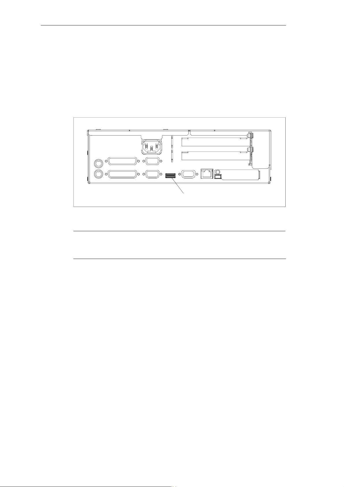
You can connect peripheral devices with USB interfaces to the USB port.
Plug the USB cable into the port.
The device is automatically detected by a Plug and Play operating system, e.g.
Windows 98, and is then available.
A USB keyboard can be used to manipulate the BIOS setup.
Setting Up and Operating the SIMATIC Box PC 620
USB port
Figure 4-6 USB connection
Note
Operating systems which do not support Plug and Play (e.g. Windows NT 4.0), do
not generally allow the operation of USB devices.
SIMATIC Box PC 620 Manual
C79000-G7076-C639-04
4-9
Page 50
Setting Up and Operating the SIMATIC Box PC 620
4.3 Working with PC Cards
PC Cards
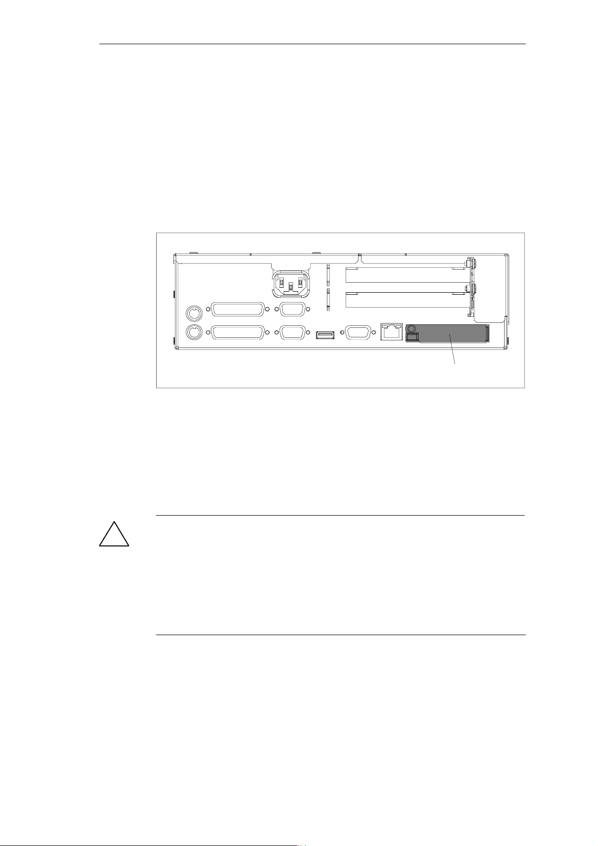
The PC card interface supports Car dbus- Car ds (32 Bit) and PCMCIA-Cards
(16 Bit) . The SIMATIC Box PC 620 has one PC card por t. You can plug communication modules for MODEM, FAX-MODEM, I SDN , Token R ing, ETHERNET,
memory expansion and SCSI interface modules in credit-card format into these
ports.
PC card interface, type I/II/III
Figure 4-7 PC Card Interface
The following is to be observed when working with cardbus/PC cards:
1. Open the port cover on the left–hand side of the device by undoing the plastic
rivet with a flat screwdriver.
2. Pull the cover out of the guide.
3. Insert the desired PCMCIA card or cardbus card.
Caution
!
Before inserting PC-Cards please make sure that the PC-Card Ejector is
completely pressed otherwise the cards e.g. Flash Memory Cards could get stuck
in the slot. The PC-Cards cannot be inserted correctly.
Always insert the PC card with the label toward the rear of the programming
device.
Do not remove the PC card while data transfer is in progress (risk of data loss and
system crash).
4-10
SIMATIC Box PC 620 Manual
C79000-G7076-C639-04
Page 51

Setting Up and Operating the SIMATIC Box PC 620
Caution
!
Before plugging in or taking out Cardbus/PC cards, you must discharge the
electrostatic of your body by briefly touching grounded object (ESD guidelines,
Section A.1).
Otherwise faults can occur.
Note
Surge currents of 650 mA at 5 V relating to 3 s are allowable!
Examples of PCMCIA cards connected to PC card interface for
Installing PC Cards
Note the following when installing these cards:
Note
Depending on the configuration of the SIMATIC Box PC 620, there may not be any
free interrupts available for operating PC Cards. You have to reserve the necessary
PC card interrupts in the BIOPS setup menu as follows:
Set the necessary interrupt via Advanced > PCI-Configuration >
PCI/PNP ISA IRQ Resource Exclusion to “reserved” (default: available).
Hard Disk 330 mA read/write
(Maxtor MXL-131-III) 640 mA spin up 2 s. . . . . . . .
110 mA idle. . . . . . . . . . . . . . . . . . . . . . . . . .
Fax/modem 60 mA idle. . . . . . . . . . . . . . . .
(Dr. Neuhaus) 140 mA transfer. . . . . . . . . . . . . .
Ethernet
(XIRCOM) 150 mA. . . . . . . . . . . . . . . . .
SIMATIC Box PC 620 Manual
C79000-G7076-C639-04
4-11
Page 52

Setting Up and Operating the SIMATIC Box PC 620
Caution
!
Risk of damage to PC cards and the SIMATIC Box PC 620!
Always insert PC cards with the front face turned toward the rear of the SIMATIC
Box PC 620. The front face generally bears the company and product designation
and is labeled ”This side up”, or words to that effect.
You might damage the SIMATIC Box PC 620 and the PC card if you attempt to
insert the PC card the wrong way round.
Before inserting the connecting cables, the electrostatic charge in your body, the
device and the connecting cables must be brought to the same potential. Briefly
touch the sheet metal case to do this.
Note
In order to use a PC card the BIOS-SETUP Main > Hardware Option
“Cardbus/PCMCIA Slot” has to be set to “Enabled”.
4-12
SIMATIC Box PC 620 Manual
C79000-G7076-C639-04
Page 53

Setting Up and Operating the SIMATIC Box PC 620
4.4 Connecting the SIMATIC Box PC 620 to other SIMATIC S5
Point-To-Point Connection
In this section, you will learn how to connect your SIMATIC Box PC 620 to a
programming device or S5 programmable logic controller using a point-to-point
connection.
You can stablish a point-to-point connection by connecting the
SIMATIC Box PC 620 to another programming device or a programmable logic
controller using
A V.24 connection
A TTY connection (not possible for the basic variant of the Box PC)
Configuring Interfaces with Line Current (TTY, 20 mA)
To ensure reliable data transfer, several factors must be taken into account. The
maximum data transfer rate (baud rate) depends on the distance, the type of
cable, the pin assignment of the interface and external interference.
You can reduce interference by choosing the right transmission cable and
connecting it properly, and by observing the following guidelines:
Use a shielded cable with a low line resistance (130 W / km) (about 40 W kft)
and low capacitance (< 90 pF/m) (about 27 pF/ft). Twisted-pair cables are less
susceptible to noise and interference. A low line resistance results in reduced
voltage excursions and shorter charge reversal times. The line resistance decreases with increasing conductor cross-section for the same length of cable.
The shorter the transmission link, the higher the maximum possible data
transfer rate.
If there is an active sender and an active receiver at the same end of the
transmission link, the sequence of access priority to the transmission circuit
must be taken into account in order to achieve the longest possible
transmission link.
Signal lines and power lines must not run together. Signal lines must be
installed as far away as possible from sources of strong interference (for
example, 400 V 3-phase power cables).
The active TTY interface with a 12 V no-load voltage has been tested on a 100
m (1100 ft) long cable at a transmission rate of 9600 bps in an environment with
normal levels of noise fieldstrengthV/mor1V/ft).If a shielded 5 x 1 x 0.14shielded
cable is used, reliable transmission is possible over a distance of up to 100 m
(1100 ft). The AS511 protocol (only one transmitter at a time) was used for
testing.
Note
The interference field of the source of interference is reduced by the square of the
distance.
SIMATIC Box PC 620 Manual
C79000-G7076-C639-04
4-13
Page 54
Setting Up and Operating the SIMATIC Box PC 620
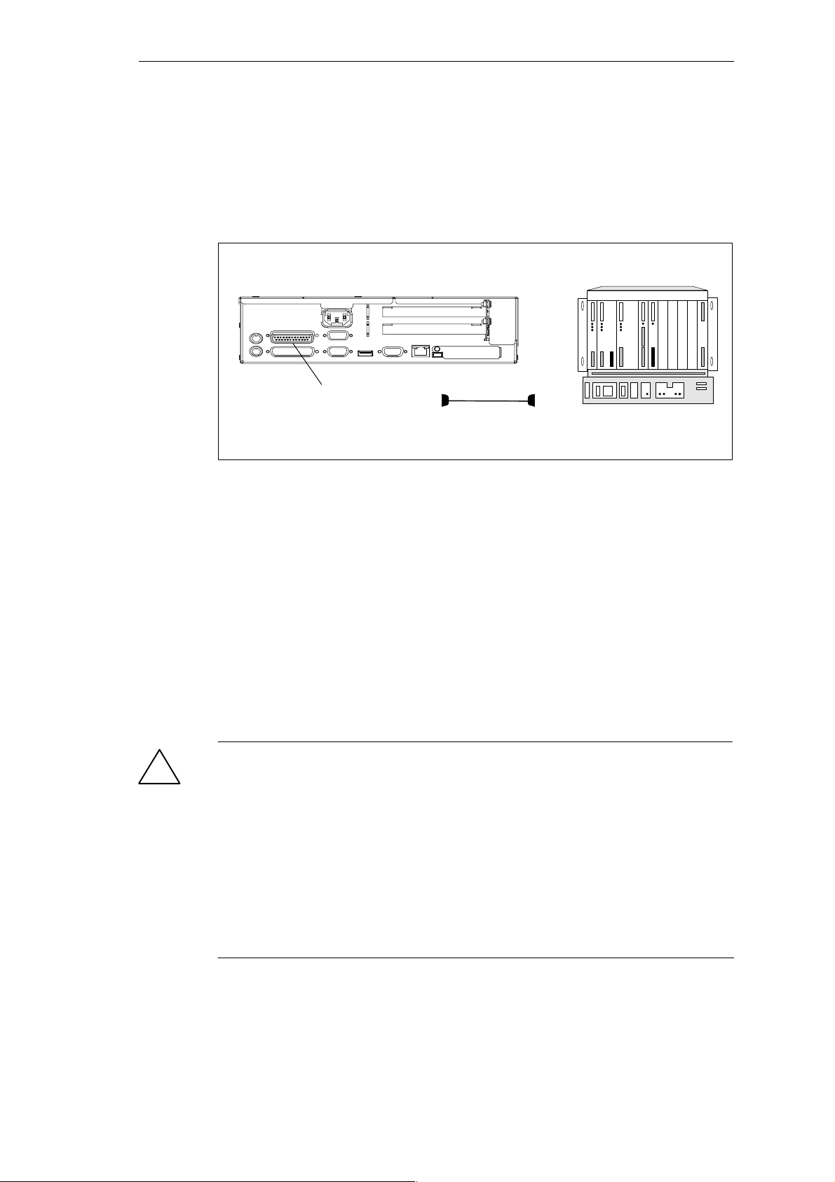
Connecting the SIMATIC Box PC 620 to an S5 Programmable Logic Controller
You can connect the SIMATIC B o x P C 6 2 0 to a SIMATIC S5 programmable logic
controller using the COM1/TTY interface port. The cable for connecting to
SIMATIC S5 CPUs is supplied with the SIMA TIC Box P C 620
( Order no.: 6ES5734-2BD20).
COM 1
(socket)
Figure 4-8 Connecting the SIMATIC Box PC 620 to an S5 Programmable Logic Controller
You connect your SIMATIC Box PC 6 2 0 to a SIMATIC S5 programmable logic
controller as follows:
1. Switch off your device.
2. Insert the connecting cable into the port
COM 1 / AG.
3. Screw down the plug.
4. Plug the cable into the corresponding port on the CPU of the programmable
logic controller.
5. In order to enable TTY operation, you must set TTY to “enabled” in the BIOS
setup.
Caution
!
Risk of damage to the Simatic Box PC 620!
The interface port may be damaged if you confuse the connections or use the
wrong connecting cables.
Make sure the TTY cable of the SIMATIC Box PC 620is plugged into the
COM 1 / TTY port and not into the LPT 1 port.
4-14
Before inserting the connecting cables, the electrostatic charge in your body, the
device and the connecting cables must be brought to the same potential. Briefly
touch the sheet metal case to do this.
Use only original cables to stablish the connection to the programmable controller.
SIMATIC Box PC 620 Manual
C79000-G7076-C639-04
Page 55

Setting Up and Operating the SIMATIC Box PC 620
Connecting the SIMATIC Box PC 620 via an Adapter
The connecting cable 6ES5 734-2BD20 is supplied with the
SIMATIC Box PC 620. An adapter is available for connecting the programmable
controller using old standard cables.
Tabelle 4-1 Adapter for SIMATIC Box PC 620 Connection
Interface Link Connecting
Cable
Order no:
6ES5 734-2BD20
TTY interface SIMATIC Box PC 620 to SIMATIC(COM 1) S5 programmable controller
6ES5 731-1xxx0
15–pin
6ES5 731-0xxx0
25– pin
Adapter
6ES5 731-6AG00
6ES5 731-6AG00
In order to maintain a data transfer rate of 9600 bps up to a distance of over
1000 m (3300 ft), the receiving diode is connected to ground (reference) via the
connecting cable
Note
You can obtain lengths differing from the standard connecting cable
(6ES5 734-2BD20) under the order number 6ES5 734-2xxx0, whereby xxx stands
for the length code.
SIMATIC Box PC 620 Manual
C79000-G7076-C639-04
4-15
Page 56
Setting Up and Operating the SIMATIC Box PC 620
SIMATIC Box PC 620 to PG Connection (V.24, TTY)
If you want to connect your SIMA TIC Box P C 6 20 to another programming device,
you can plug the appropriate connecting cable into the V.24 or TTY interface port
Tabelle 4-2 Connection of the SIMATIC Box PC 620 to other PUs
Interface Link Connecting Cable
Adapter
Order No.:
COM 1 as a
PG 7xx with PG 7xx 6ES5 733-5BD20
2)
V .24 port
COM 1 as a
TTY port
PG 7xx with PG 6xx Series connection of
6ES5 733 -2xxx0
and
6ES5 731-6AG00
2)
1)
6ES5 731-6AG00
Note
1. When connecting the programming devices in series, make sure you connect the cable
the right way around (see Figure 4-9).
2. The connecting cable is available for order only as a spare part. The connecting cable is
described in Chapter 8.
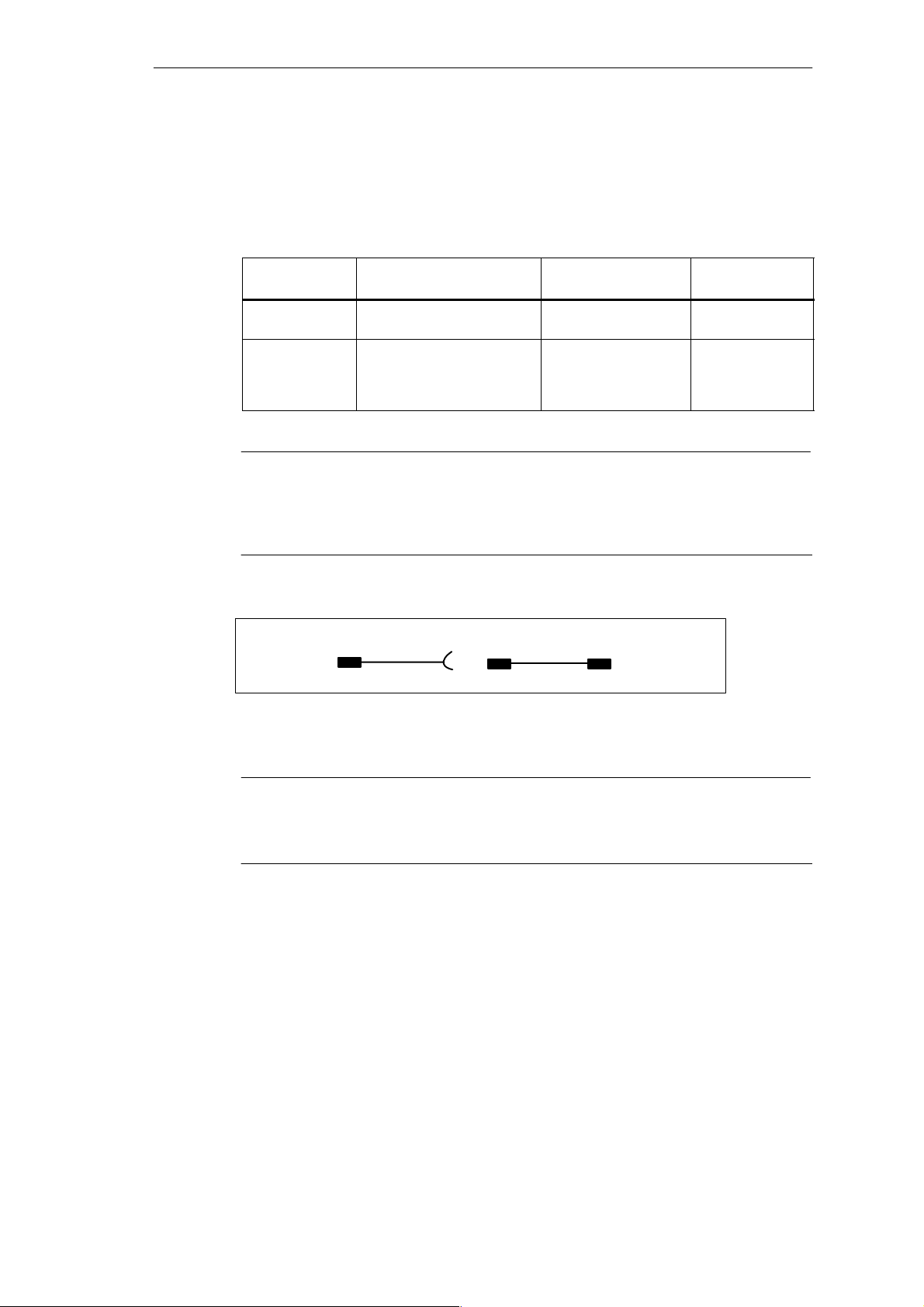
Adapter Connecting cable
PG 7XX
Active Passive
6ES5 731–6AG00 6ES5 733–2xxx0
PG 6XX
Figure 4-9 Direction of Connection: Adapter – Connecting Cable
Note
For the PC/PU connection, you must switch the TTY ports (COM 1) in one of the
programmable logic controllers to passive by changing the jumper setting. When
the SIMATIC Box PC 620 leaves the factory, this interface is always set to active!
4-16
SIMATIC Box PC 620 Manual
C79000-G7076-C639-04
Page 57
Setting Up and Operating the SIMATIC Box PC 620
Switching the SIMATIC Box PC 620 to Active/Passive
When your SIMATIC B ox PC 620 is supplied, the COM1 (TTY) serial port is active
(20 mA current loop). When you connect two programming devices using the
COM1 (TTY) serial port, you must deactivate the port on one of these devices. In
the SIMATIC Box PC 620, the switch for this is loc at ed on the motherboard.
These jumpers are accessible if you open the battery compartment cover.
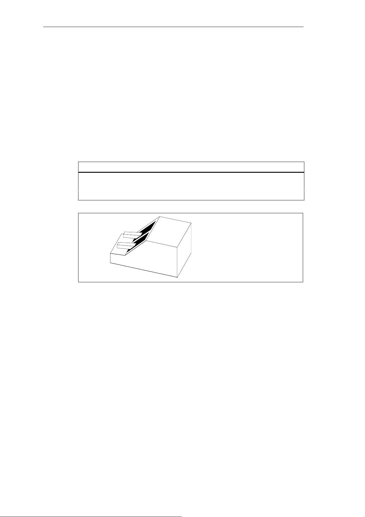
Jumper Settings
Change the jumper settings as shown in Figure 4-10.
S1-1 S1-2 Function
on on Active TTY port (default setting)
on off TTY loop transmit separated from power source (passive setting)
off on TTY loop receive separated from power source (passive setting)
on
Figure 4-10 Jumper Setting TTY Port Active
Changing the Jumper Setting
Proceed as follows to switch the SIMATIC Box PC 620 to passive:
1. Switch off your device.
2. Open the cover of the module.
3. Place the two jumpers in the “open” position (see Fig. 1-10).
4. Close the cover of the module.
1
2
off
SIMATIC Box PC 620 Manual
C79000-G7076-C639-04
4-17
Page 58
Setting Up and Operating the SIMATIC Box PC 620
4.5 Connecting the SIMATIC Box PC 620 to a SIMATIC S7 Network (MPI/DP)
Connecting an S7 Programmable Controller via MPI/DP Interface
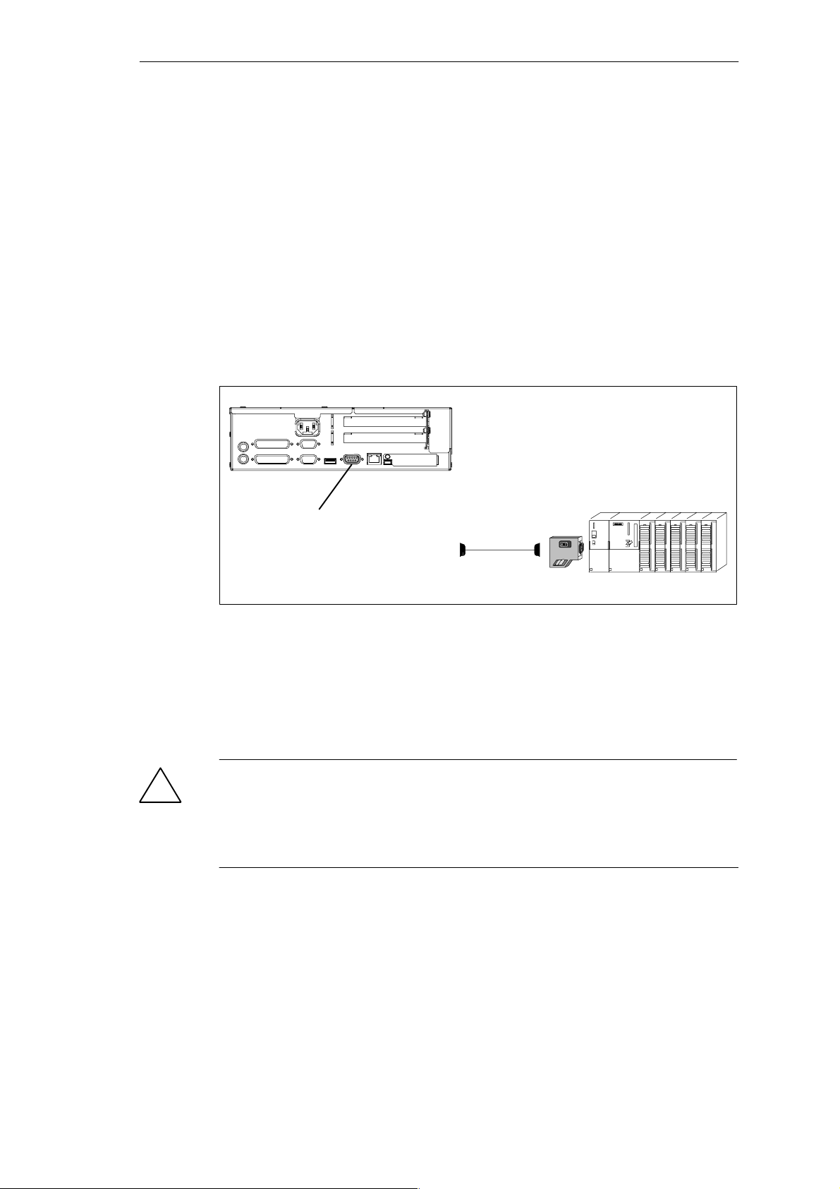
You can connect the SIMATIC Box PC 620 to a SIMATI C S7 automation system
or to a PROFIBUS network via the pot ent ially isolated*) MPI/DP port**) .
The MPI cable (5m ) for connec t ion to SIMATI C S7 CPUs (order no.:
6ES7901-0BF00-0AA 0) is supplied with the SIMATIC Box PC 620. Only
transfer rates of up to 187. 5 kBit/s are possible with this cable connec t ion. The
12 Mbit/s PROFIBUS connecting cable is required for baud rates from
1.5 Mbit/s ( order no. 6ES7901-4BD00-0XA0).
In disturbed surroundings:
bus connector
6ES7972-0BB10-0XA0
or
6ES7972-0BB20-0XA0
MPI/DP port
Figure 4-11 Connection Using the MPI/DP Interface
6ES7901-0BF00-0AA0
(5 m length
Proceed as follows when connecting to a SIMATIC S7 programmable logic controller:
1. Switch off your device.
2. Connect the cable to the MPI/DP interface.
Caution
!
Risk of damage to the SIMATIC B ox PC 620!
Before plugging in the cables, the static charge on your body, the unit, and the
cables must be equalized. You can do this by briefly touching the metal mounting
plate for the interfaces on the left-hand side panel.
* Electrical isolation in the saftey extra-low voltage circuit (SELV circuit).
** Not available for the basic variant of the Box PC.
4-18
SIMATIC Box PC 620 Manual
C79000-G7076-C639-04
Page 59

Connecting
Via the MPI/DP interface, you can connect your PC to
MPI networks (S7-200, S7-300, and S7-400) or
PROFIBUS DP networks (DP components).
MPI/PROFIBUS Network
Up to 32 devices (PC, programming device, or programmable controller) can be
connected to the MPI/DP interface to form a network segment. The physical
connection to the MPI/PROFIBUS DP network is via a floating RS485 interface
which is a component of the PC basic module.
Several MPI/PROFIBUS DP network segments can be connected via repeaters.
The complete MPI/PROFIBUS DP network can comprise up to 127 stations. Data
transmission rates from 9.6 Kbps to 12 Mbps are possible in the
PROFIBUS DP MPI network.
Setting Up and Operating the SIMATIC Box PC 620
Note
You will find more information on setting up an MPI/DP network in the manual
”PROFIBUS Networks” Order No.: 6GK 1970-5CA10-0AA0 or in SIMATIC NET.
SIMATIC Box PC 620 Manual
C79000-G7076-C639-04
4-19
Page 60

Setting Up and Operating the SIMATIC Box PC 620
4.6 Networking the SIMATIC Box PC 620 with Other Stations on PROFIBUS
Networking the SIMATIC Box PC 620 on PROFIBUS
PROFIBUS is an open and robust bus system for industrial use. It can be used to
configure networks with up to 32 stations per segment. PROFIBUS -DP s uppor ts
data-transfer rates from 9.6 Kbaud to 12 Mbaud.
How the Network Functions
The network operates on the master-slave principle with token passing (complying
with DIN19245, PROFIBUS). It distinguishes between active and passive stations.
An active station receives the token and passes it on to the next station within a
specified time.
Hardware Requirements
Using the following components, for example, you can connect or network the
SIM A T I C Bo x PC 620 with PROFIBUS:
RS 485 MPI/DP interface adapter (not available for the basic variant of the
Box PC)
Shielded, twisted pair (bus cable or connecting cable to network).
Note
You will find more detailed information about the SIMATIC Net PC cards in the
SIMATIC NET Catalog IK 10.
4-20
SIMATIC Box PC 620 Manual
C79000-G7076-C639-04
Page 61

Setting Up and Operating the SIMATIC Box PC 620
4.7 Networking the SIMATIC Box PC 620 and Other Computers on Industrial Ethernet
Networking the SIMATIC Box PC 620 on Industrial Ethernet
Industrial Ethernet is a bus system for industrial use based on Ethernet
(ISO 8802/3). The main features of Industrial Ethernet are:
speed (10 Mbps), simple expansion, open communication, and widespread
application.
How the Network Functions
Industrial Ethernet is the name of Siemens networks and network components
operating according to the CSMA / CD (Ethernet) principle. Industrial Ethernet is a
bus-type LAN that uses a triaxial cable (H1) as its transmission medium.
Note
You will find more detailed information about the SIMATIC Net PC cards in the
SIMATIC NET Catalog IK 10.
4.8 Connection under Windows
Windows supports point-to-point connections via the LPT or COM port. The
connecting cables are standard, commercially available products. More information
is available in the Networks section of the Windows description and in the online
Help system under “Connection to Another Computer”.
SIMATIC Box PC 620 Manual
C79000-G7076-C639-04
4-21
Page 62

Setting Up and Operating the SIMATIC Box PC 620
4-22
SIMATIC Box PC 620 Manual
C79000-G7076-C639-04
Page 63

SIMATIC Box PC 620 Expansions
What Does This Chapter Contain?
You can enhance the performance of your SIMATIC Box PC 620 by adding
additional memory. This chapter describes how to expand your
SIMATIC Box PC 620. Please observe the relevant safety guidelines.
Chapter Overview
In chapter you will find on page
5.1 Opening the Unit 5-2
5.2 Installation of a Memory Extension 5-5
5.3 Replacing the Backup Battery 5-6
5.4 Installation of Expansion Cards 5-13
5.5 Removal and Installation of Drives 5-18
5.6 Removal and Installation of the Power Supply Unit 5-23
5.7 Removal and Installation of the Bus Board 5-24
5.8 Removal and Installation of the Fan 5-26
5.9 Processor upgrade 5-27
5.10 Switch Adjustment / Jumpers 5-28
5.11 Reset Button 5-29
5
SIMATIC Box PC 620 Manual
C79000-G7076-C639-04
5-1
Page 64
SIMATIC Box PC 620 Expansions
5.1 Opening the Unit
5.1.1 Prerequisites
The device is designed for easy maintenance so that any work that is necessary
can be done quickly and at low cost.
Caution
!
The electronic components on the printed circuit boards are extremely sensitive to
electrostatic discharge. Certain precautionary measures are therefore necessary
when handling such components. These measures are explained in the guidelines
for handling electrostatically sensitive devices at the end of this manual.
Limitation of Liability
All technical specifications and licences apply only to expansion functions
approved by SIEMENS.
No liability can be accepted for impairment of functions caused by the use of
devices and components of other manufacturers.
All the modules and components in the SIMATIC Box PC 620 are electrostatically
sensitive. Please read the ESD guidelines at the end of this book carefully. The
following symbol warns that electrostatically-sensitive modules are present.
5-2
SIMATIC Box PC 620 Manual
C79000-G7076-C639-04
Page 65

Before Opening the Unit
Note the following rules before opening the unit:
S Before you disconnect the power supply cable, discharge any electrostatic
charge on your body. You can do this by touching the metal mounting plate for
the interfaces on the left-hand side panel of the unit.
S Discharge any electrostatic charge from tools that you are using.
S Wear a grounding wrist-strap if you are handling components.
S Leave components and modules in their packing until you are ready to install
them.
S Disconnect the SIMATIC Box PC 620 from its power supply and remove the
battery before plugging in or removing any modules or components.
S Touch components and modules only on their edges. Above all, do not touch
the connecting pins and printed conductors.
S Never operate the SIMATIC Box PC 620 with the cover open.
SIMATIC Box PC 620 Expansions
Tools
You can carry out all necessary installation work on the SIMATIC box PC 620 with
screwdrivers of the type TORX T10 and TORX T8.
SIMATIC Box PC 620 Manual
C79000-G7076-C639-04
5-3
Page 66
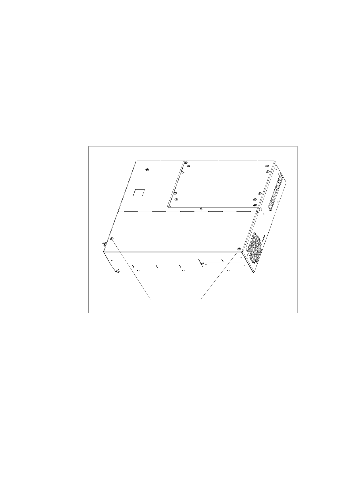
SIMATIC Box PC 620 Expansions
5.1.2 Opening the SIMATIC BOX PC 620
To open the SIMATIC Box PC 620, proceed as follows:
1. Switch off the SIMATIC Box PC 620, pull out the power supply connector, and
remove all connecting cables from the unit, including the keyboard cable.
2. Remove the PC from its mounting/cabinet (only necessary if screws which have
to be removed are inaccessible in the fitted position).
3. Undo the two screws (see fig. 5-1) on the housing cover.
4. Raise the cover slightly.
5. Then you can remove the housing cover.
5-4
Screws on the housing cover
Figure 5-1 SIMATIC Box PC 620 Prepared for Opening
SIMATIC Box PC 620 Manual
C79000-G7076-C639-04
Page 67
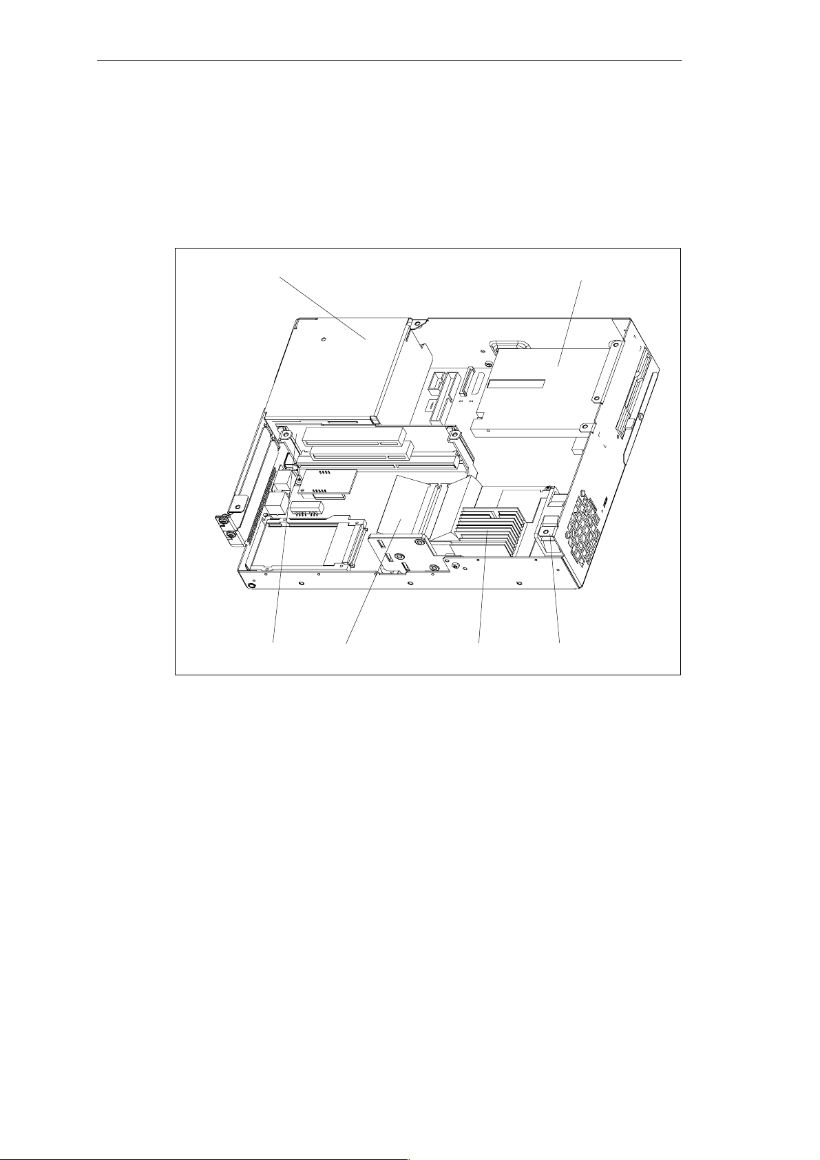
SIMATIC Box PC 620 Expansions
5.1.3 Components Visible After Opening the Unit
Components
Once you have removed the top cover of your unit, the components are visible.
Power supply unit
Bus board Memory extension
Processor
Floppy drive or LS 120
Fan
Figure 5-2 SIMATIC Box PC 620 Open
SIMATIC Box PC 620 Manual
C79000-G7076-C639-04
5-5
Page 68
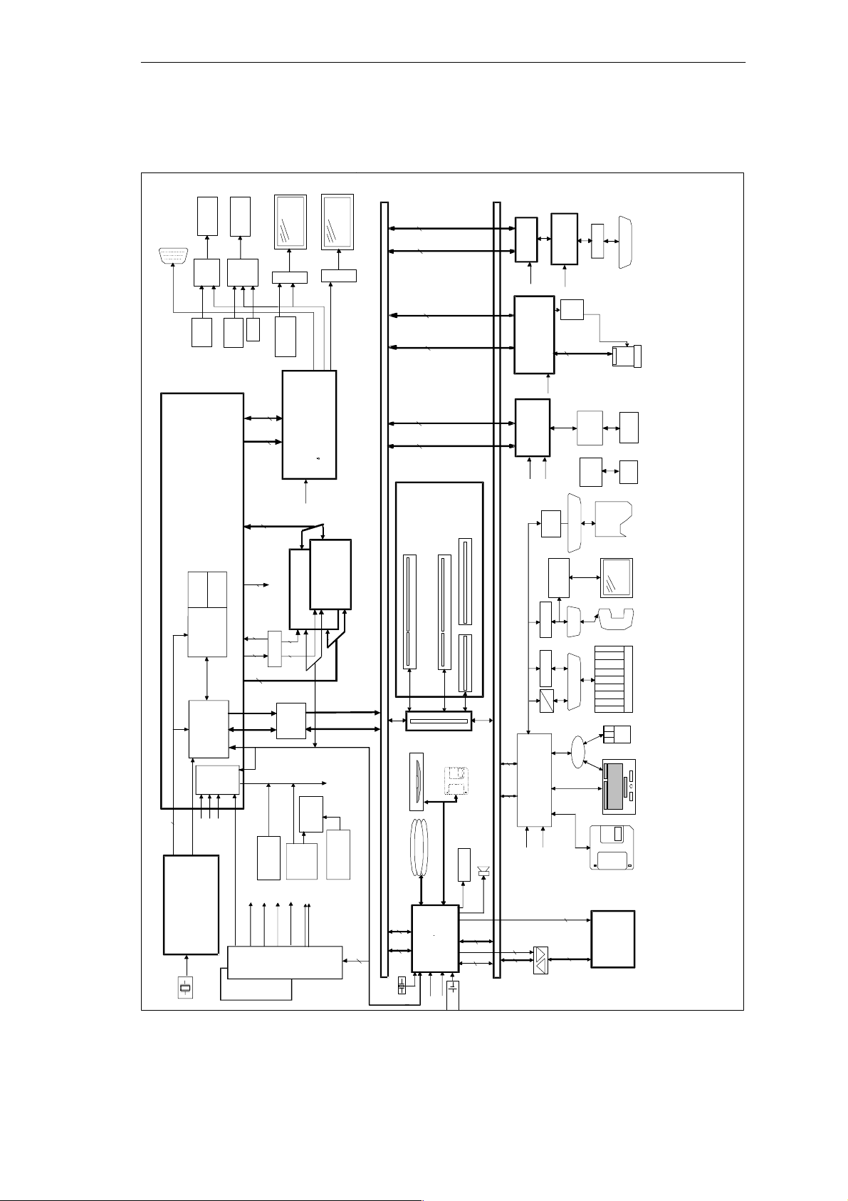
SIMATIC Box PC 620 Expansions
5.1.4 Block Diagram of the Motherboard
local
fronts
USB–Taco
ext. XGA
1280x1024x256
Plug
module
P&D–
USB
400 PIN BGA socket
Embedded Mobile Module (EMC2)with
VRM, L2–Cache, 440BX,Thermal sensor
L1–Cache
Prozessor
440BX
V_3
2
+3,3V
PCLK
HCLK
24MHz Clock (Super–I/O )
100/66MHz Clocks ( HOST )
33MHz Clocks ( PCI )
Clock synthesizer
14.318 MHz
Status–Led’s
Fronts
for
I/O–SS
USB
(channel 1)
LED’s
(channel 0)
AGP 1X
4
L2–Cache
2
2,5V I/O
1,7V Core
300–366 MHz
GTL–Bus
V_5
+5V
48MHz Clock ( USB )
14,318MHz Clock
VRM
V_DC
+5V
48TSSOP
492 BGA
2,5 / 3,3V
VR_ON
PS_PWROK
DC
+ 3,3V
Power–
1
+ 5V
Supply
5V–CMOS–
DSTN/TFT–Display
5V–CMOS
Contrast
voltage
3.3V
32
AD(0:31)
26
CTRL
VGA–Controller
66MHz
MD(0.63)
64
3,3V
Module ID
33
3,3V–PCI
Reset button
AC
24V
Bank 3/4
2 2
Clockbuffer
3,3–to–5V–
Translator
– 12V
+ 12V
Power–
Supply
110V /
Bank 1/2
EDO / SDRAM
SM–BUS
LED’s
Relay
Watchdog
+ – 18V pot.frei
220V
TFT–LVDS–Display
LVDS
C T B69000
2MB SGRAM integrated
3,3V
EDO / SDRAM
RAS/CSA 2 / 3
CKE2/3
MA0..13
SYSTEM–RESET
Temp.
CKE0/1
RAS/CSA 0 / 1
CAS/DQMA 0..7
SRAS,SCAS,CKE0..3,WE
RAS/CSA 0..3
CTRL
AD(0:31)
monitoring
2
SM–BUS
1 PCI–Slot
Secondary IDE
Primary IDE
3.3/5 V PCI – BUS AD(0..31), CTRL(26) ( 33 MHz Bustakt )
2632
CTRL
AD(0:31)
32KHz
AD ( 0..31)
2632
Cntl.
AD ( 0..31)
26
Cntl.
32
AD ( 0..31)
2632
Cntl.
1 shared
ISA / PCI–Slot
Bus module
RISER
CDROM option
USB Port1/2
ATA–33 hard disk 2.2”/3.5”
BGA 324
SA(0:23)
SD(0:15)
DREQ(0:7)
DACK(0:7)
70
ACPI
PIIX4E
Systemcontroller
5
CTRL
48MHz
33MHz
3 / 3.6V
LS 120 floppy option
int. Speaker
IRQ(1:15)
PCI9050
33MHz
Card–Bus
Intel 10/100MBit–
33MHz
SA(0:15),SD(0:7),IRQ(1:15),
DRQ(0:3),DACK(0:3)
48
Ultra–IO
7
CTRL
24MHz
ISA–BUS 16Bit Daten, 24Bit Adressen, 5V
2
8
SD(0:7)
160 PQFP
ASPC/2
max. 128k Memory
48MHz
VCC/
(208TQFP)
PCI 1211
60
33MHz
BGA256
Ethernet 82559
25MHz
protection
RC network
alternative
COM2
V24
V24
TTL
TTY
160PQFP
FDC37B727
32kHz
3
Page–Select
für 4
128 K–Pages
8
100 PQFP
VPP
A(0:25)
D(0:15)
CTRL(18)
LPT1
COM2
COM1
MUX
XD(0:7)
RS485 Hybrid
Ethernet
transformer
USB
(Channel 0)
EPP/ECP
Touch–
BIOS
29F040
512KByte
RS485
L2–DP
12MB/s
Slot1
Typ e I/II/III
PCCard
RJ45
USB
socket
Printer
Centronics
Option
e.g. modem
TTY/AG
Communication
PS/2
mouse
Keyboard / track ball
3.5”Floppy
1.44 MB
32 PLCC
Figure 5-3 Block Diagram, SIMATIC Box PC 620
5-6
SIMATIC Box PC 620 Manual
C79000-G7076-C639-04
Page 69
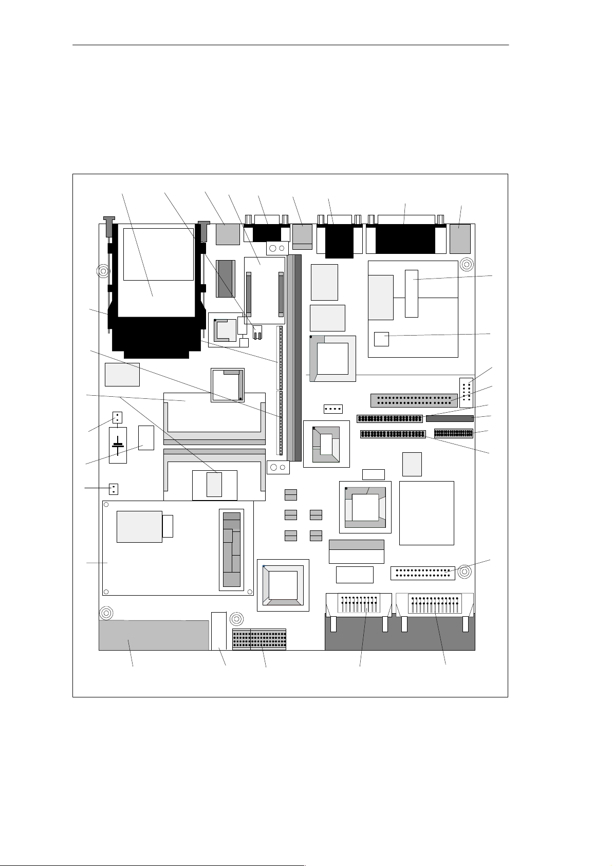
5.1.5 The Motherboard
The motherboard is the heart of the SIMATIC Box PC 620. Here, data is
processed and stored, and interfaces and device I/Os are controlled and
managed.
SIMATIC Box PC 620 Expansions
8 10 11 12 13
9
14 (up)
15 (down)
X40
X503
LCD–VGA–
X1 – Bus connector (EISA slot)
CBT
CBT
CBT
Controller
Chips & Techn.
X410,
B69000
X411
USB
X11
D94
DP12–
Controller
ASPC/2
DP12–
SRAM
D95,96
D90
DP12–
Host–Bridge
PLX9050
HD–SV
X25
FDC
D19
ISA
CBT
D3 – D7
CBT
X4
LPT/
COM
X3
Ultra I/O
SMSC 37B727
PCI
D9
USB
5V
CMOS–
D145–148
Treiber
5V
LVDS
D112
3,3V / 5V–LVDS–TFT–Display
X400
RJ45
X805
Z1
7
6
N6
TPS2211
X600
D143
D156
5
X24
(CMOS
Battery)
4
X20
(DRAM
slot 1)
H1
speaker
Ethernet
Ethernet–
Contr.
Cardbus
Controller
w. LEDs
transformer
82559
PCI1211
Quarz
E2
X800
X504
S1
DP12–
RS485 module
(TTY
aktiv/passiv)
X18 (TTY Hybrid X3133)
X17 (TTY Hybrid X3134)
DRAM
3
X19
(DRAM
slot 2)
2
X28
(fan)
D1
Clock–
generator
Quartz
1
Fan
D2
Clock
D2
Buffer
VCC
PIIX
MD1/3
3,3V–PCI
AGP
EMC–2 processor
module (Pentium II/Celeron)
S 2 – Reset
MA/MC
MD0/2
X12
D159
CRT
P&D–Interface
ISA
X41
Quartz
PIIX4E
+EMV
3,3V
X9
D157,158
N7
prim. IDE 2,5’’
sec. IDE 2,5’’
IDE
CPU
16 (up)
17 (down)
V24 driver
LM77
prim. IDE 3,5’’
X420
X44
X14 PSU
D11
BIOS
TFT / DSTN
5V–CMOS–Display
ESD/EMV
D95,96, D100–102,
other
logic circuits
FRONT–IF
LPT1/COM1,2
D105–109
X5
X31
18 (up)
19 (down)
X6
2xPS/2
DP12 peripherals
X26 (alt.
COM2)
NB–Floppy
sec. IDE LS120
20
21
22
23
24
25
26
27
28
Figure 5-4 Motherboard
SIMATIC Box PC 620 Manual
C79000-G7076-C639-04
313233
30
29
5-7
Page 70

SIMATIC Box PC 620 Expansions
Components on the Motherboard
The following components are located on the motherboard of the
SIMATIC Box PC 620:
Serial
Number
1 Processor module with heat sink
2 Connector for fan
3 Loudspeaker
4 Connector for clock battery
5 System memory, 2 slots
6 TTY transmitter *
7 TTY receiver*
8 PC card slots
9 DIP switch TTY active/passive*
10 RJ45 socket for ethernet LAN
11 DP12 RS485 module*
12 MPI/DP port
13 USB bus connector
14 Serial port COM 2,
15 Socket for VGA monitor
16 Serial port COM 1/TTY
17 Parallel port LPT 1
18 PS/2 mouse connection
19 PS/2 keyboard connection
20 Connection to power supply (power supply unit)
21 Temperature sensor
22 Connector alternative
23 IDE connector for 3.5 “ hard disk
24 IDE connector for 2.5 “ hard disk
25 Floppy drive connector
26 IDE connector for LS 120
27 IDE connector for CD-ROM
28 Connector for 5 V CMOS display
29 Connector for front interface
30 Connector for LVDS display (3.3 V/5 V)
31 Slot for P&D interface module
32 Button for hardware reset
33 Fan
1
1
1
Functions
1
5-8
*1Not available for the basic variant of the Box PC.
SIMATIC Box PC 620 Manual
C79000-G7076-C639-04
Page 71
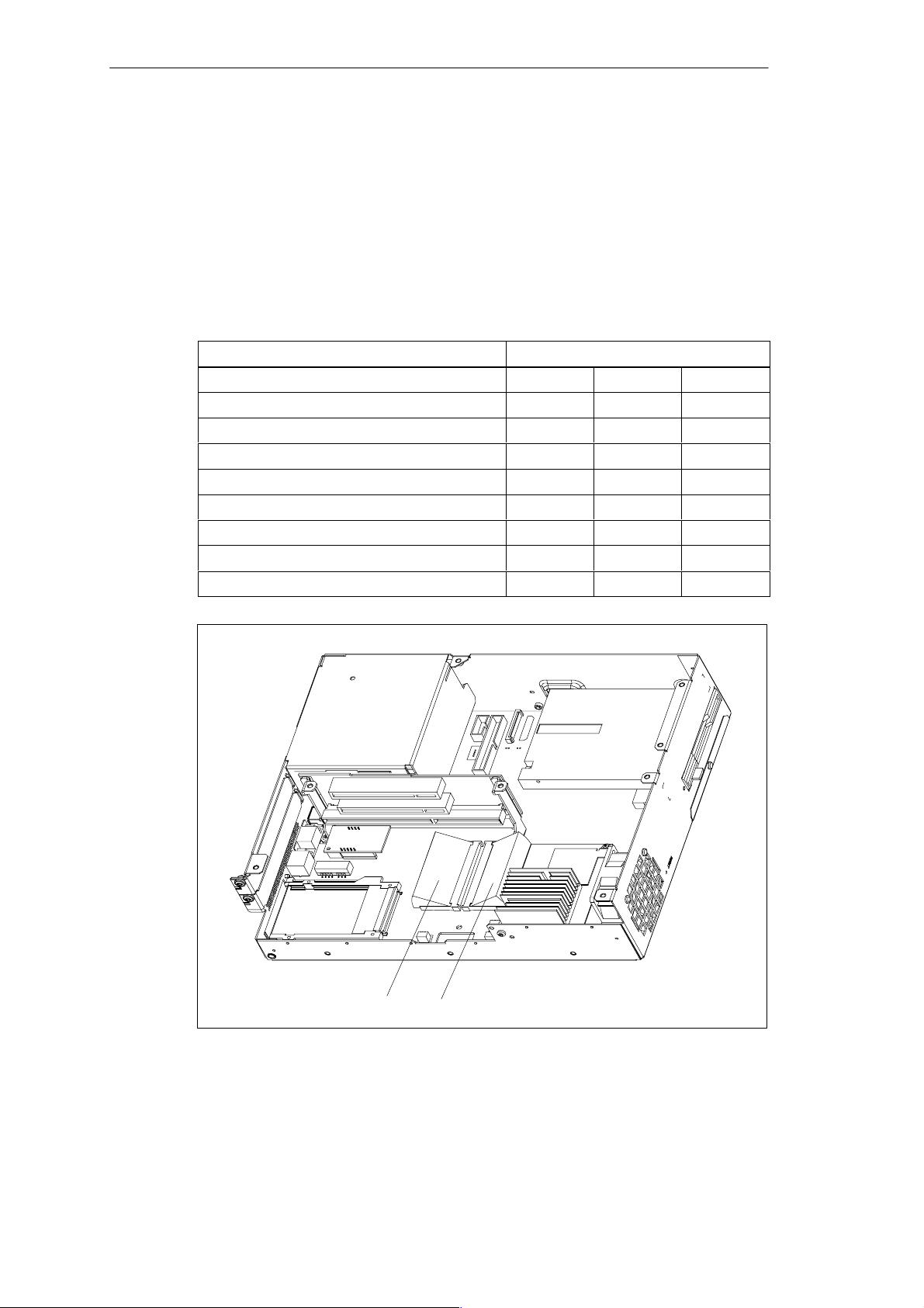
SIMATIC Box PC 620 Expansions
5.2 Installing Memory Expansion Submodules
Standard Memory
The motherboard has 2 slots for 144 pin SO DIMM memory submodules. This
allows you to expand the memory capacity of your SIMATIC Box PC 620 to a
maximum of 512 Mbytes.
Either one or two modules can be installed.
Memory Modules
64 Mbytes 128 Mbytes 256 Mbytes
64 Mbytes 1 – –
128 Mbytes 2 – –
128 Mbytes – 1 –
192 Mbytes 1 1 –
256 Mbytes – – 1
256 Mbytes – 2 –
384 Mbytes – 1 1
512 Mbytes – 1 –
Figure 5-5 Position of the SO DIMM Memory modules
SIMATIC Box PC 620 Manual
C79000-G7076-C639-04
Bank 0 Bank 1
5-9
Page 72

SIMATIC Box PC 620 Expansions
Caution
!
The electronic components of the printed circuit boards are extremely sensitive to
electrostatic discharge. Certain precautionary measures are therefore necessary
when handling such components. These measures are explained in the guidelines
for handling electrostatically sensitive devices at the end of this manual.
Installing the SO DIMM Cards
To plug in expansion submodules, proceed as follows:
1. Open the unit as described in Section 5.1.
2. Plug the cards into the slots. Note the safety recess on the connector side of
the SO DIMM card.
3. Push the card down applying light pressure until it locks into place.
4. Close the unit.
!
Installation
Caution
Risk of damage!
Make sure that the cards sit securely in the slots, otherwise they can fall out and
be damaged.
The memory configuration is detected automatically. When you switch on the unit,
the distribution of base and extended memory is displayed on the screen.
5-10
SIMATIC Box PC 620 Manual
C79000-G7076-C639-04
Page 73

SIMATIC Box PC 620 Expansions
5.3 Replacing the Backup Battery
Battery Power Supply for Real-Time Clock and Configuration
A backup battery (3.6 V-lithium battery) powers the the real-time clock even after
the SIMATIC Box PC 620 is switched off. In addition to the time of day, all the information about the SIMATIC Box PC 620 (device configuration) is stored in RAM.
If the backup battery fails or is removed, all these data are lost.
The clock uses very little power and the lithium battery has a high capacity so that
the battery can provide backup power for the real-time clock for many years and
seldom needs to be replaced.
Battery Voltage too Low
If the battery voltage is too low, the time is lost, and a correct configuration of the
device can no longer be guaranteed.
Replacing tthe Battery
In this case, you must replace the backup battery. The battery is on the
motherboard.
To change the battery, proceed as follows:
1. Switch off your SIMATIC Box PC 620 and remove the power cable and all the
connecting cables.
2. Open the unit as described in Section 5.1.
3. Change the backup battery inserted in the motherboard by pulling out the
connector and undoing the cable tie.
4. Secure the new battery in its mounting with a cable tie.
5. Insert the battery connector in the motherboard.
6. Close the unit.
SIMATIC Box PC 620 Manual
C79000-G7076-C639-04
5-11
Page 74
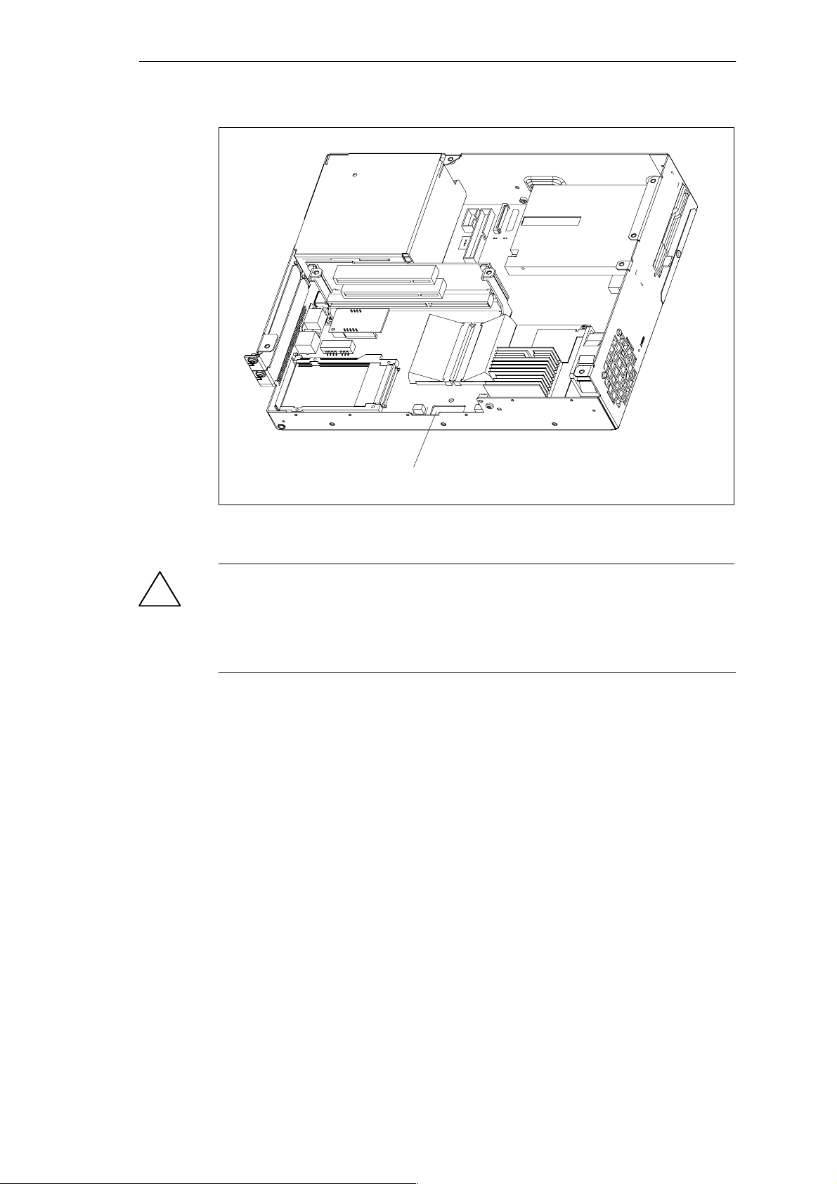
SIMATIC Box PC 620 Expansions
Figure 5-6 Position of the Backup Battery
Caution
!
Risk of damage!
Only replace the lithium battery with an identical battery or with a type
recommended by the manufacturer (Order No.: W79084-E1003-B1).
Dispose of used batteries in keeping with local regulations.
Changing SETUP
If you change the battery or unplug the battery connector you must run the SETUP
program to reset your programming device’s configuration data (see Chapter 6).
Backup battery removed
5-12
SIMATIC Box PC 620 Manual
C79000-G7076-C639-04
Page 75
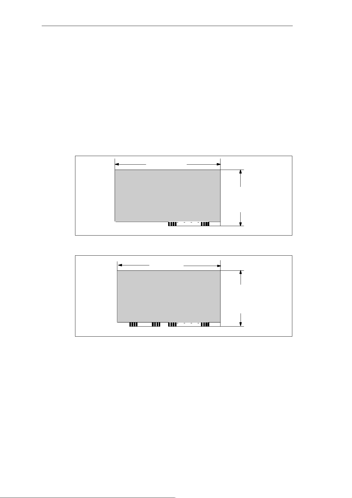
5.4 Installation of Expansion Cards
Notes about the Cards
The SIMATIC Box PC 620 is designed for the use with cards as per the AT/
PCI specification.The dimensions of the cards may not exceed the stated
dimensions. If the height is exceeded, contact problems, malfunctions and
difficulties with the assembly cannot be excluded. The illustrations show cards with
a full AT/PCI overall length. Depending on the slot, there may be restrictions on the
overall length.
175 mm
6,89 ”
SIMATIC Box PC 620 Expansions
Figure 5-7 XT Card
Figure 5-8 AT Card
A31 A1
175 mm
6,89 ”
A31 A1C18 C1
4,201”
106,7 mm
4,8”
121,92 mm
SIMATIC Box PC 620 Manual
C79000-G7076-C639-04
5-13
Page 76
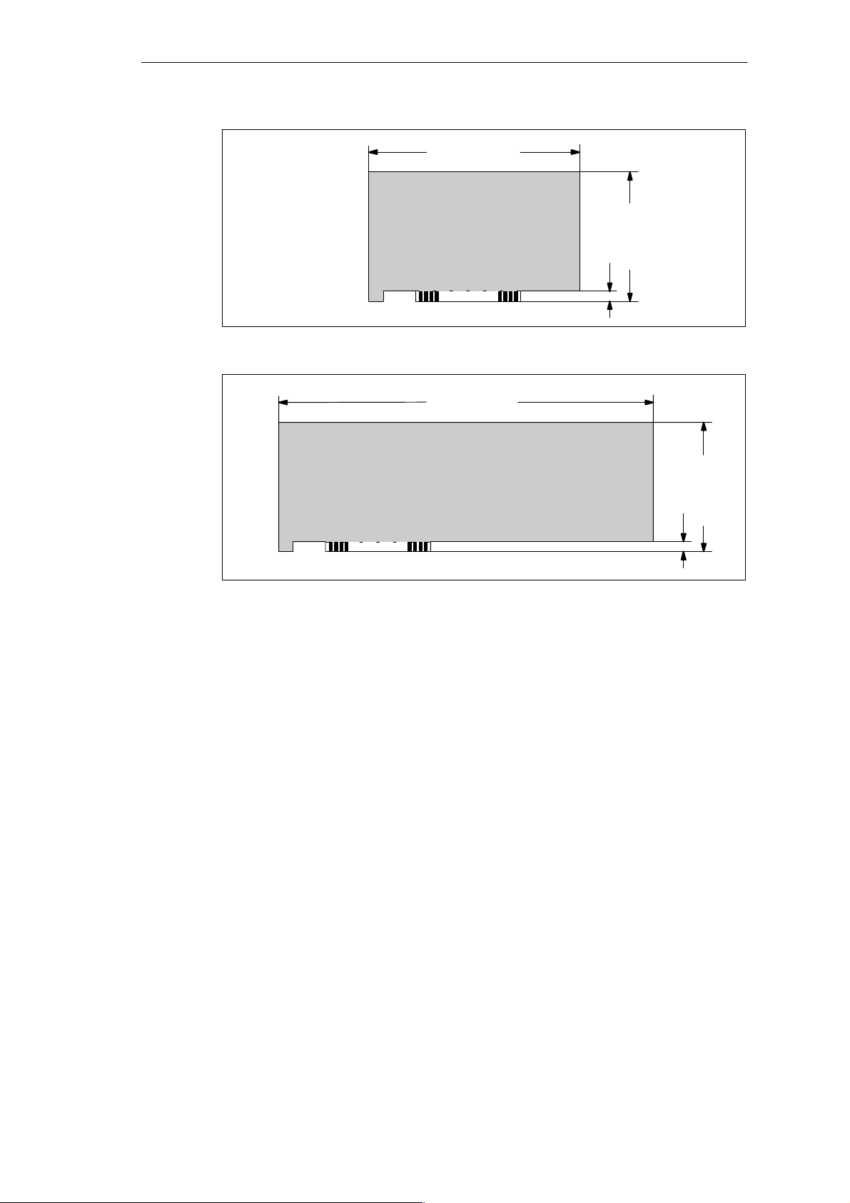
SIMATIC Box PC 620 Expansions
Figure 5-9 Short PCI Cards (5 V)
174,63 mm
6,875”
265 mm
10,48 ”
8,19 mm
0.322”
4,2”
106,68 mm
Figure 5-10 Long PCI Cards (5 V)
Note about Long PCI Cards
Before long PCI cards can be inserted into the guides of the fan trough, they must
be fitted with a so-called extender (this should form part of the scope of
supply of long PCI boards). Long PCI cards can be inserted into the guides of ISA
modules by means of this extender.
8,19 mm
0.322”
4,2”
106,68 mm
5-14
SIMATIC Box PC 620 Manual
C79000-G7076-C639-04
Page 77
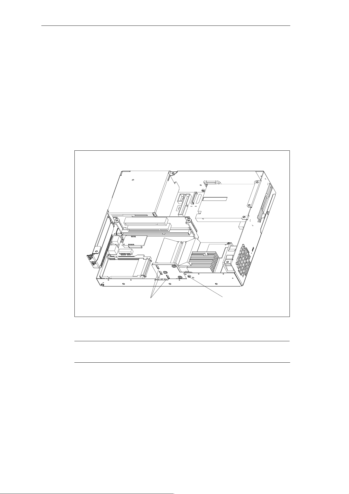
SIMATIC Box PC 620 Expansions
5.4.1 Removal and Installation of the Device for Holding Down the modules
The device for holding down the modules is attached to the housing with a screw.
It has three slits, through which the slide elements are inserted.
Proceed as follows:
1. Open the housing as described in Section 5.1.
2. Undo the fixing screw of the device for holding down the modules.
3. During assembly, ensure that the device for holding down the modules is
resting on the guide on the housing.
Figure 5-11 Removal/Installation of an Expansion Card
Note
The slide elements are in the enclosed plastic bag.
SIMATIC Box PC 620 Manual
C79000-G7076-C639-04
Guide slits for slide elements
Fixing screw for device for
holding down the modules
5-15
Page 78

SIMATIC Box PC 620 Expansions
Aligning the Holding-Down Device
Proceed as follows to install the holding-down device.
1. Insert the slide element through the guide slit until it is resting firmly on the
module. The module must now be introduced into the notch.
Caution
!
No pressure may be exerted on the module! Therefore, do not use force to press
the slide element onto the module.
2. Cut off the projecting part of the slide element:
– Score the slide element at the top edge of the holding-down device with a
knife and break it off.
– Nip off the surplus with a sharp side cutter.
5-16
SIMATIC Box PC 620 Manual
C79000-G7076-C639-04
Page 79
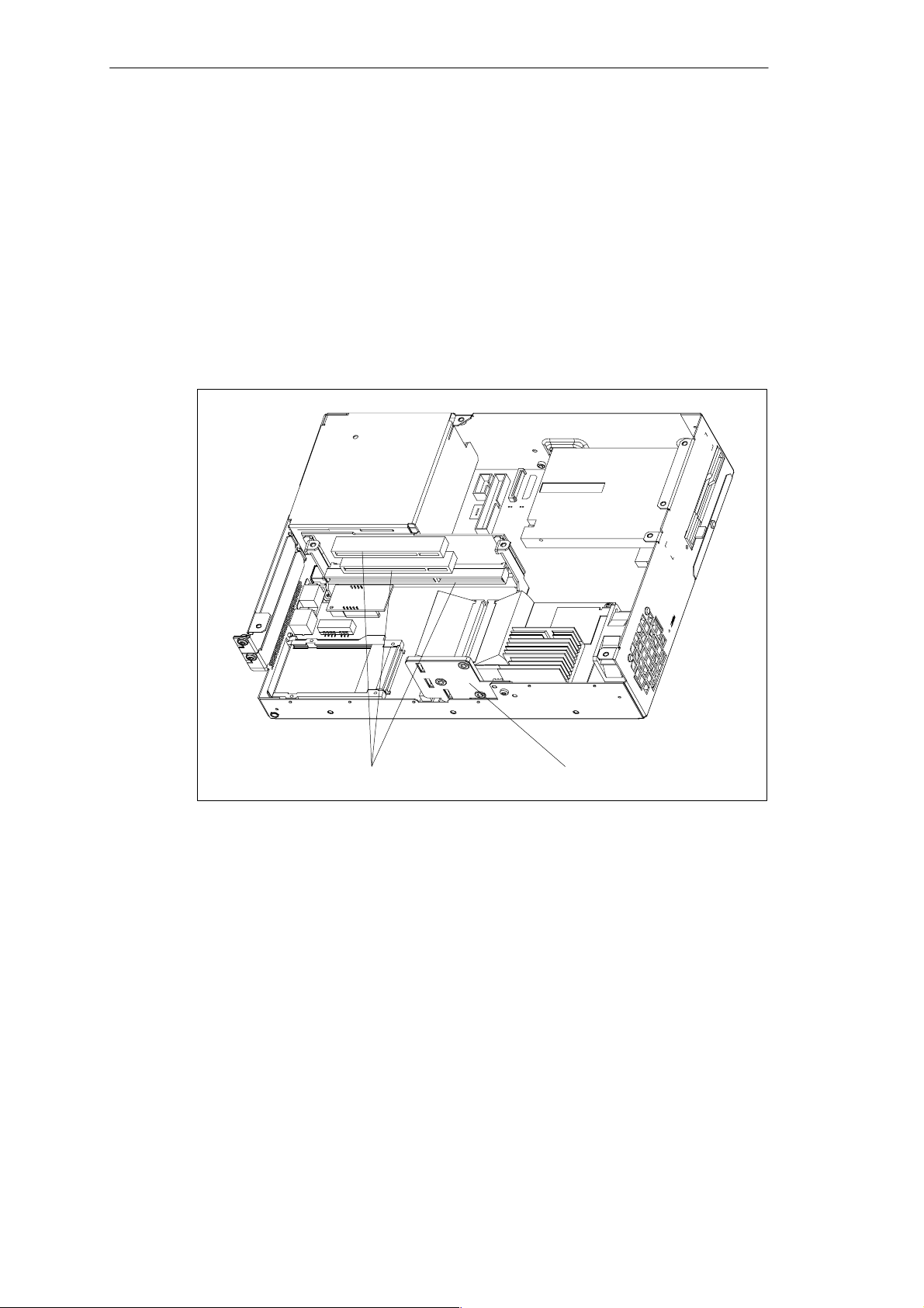
SIMATIC Box PC 620 Expansions
5.4.2 Removal and Installation of an Expansion Card
Proceed as follows:
1. Open the housing as described in Section 5.1.
2. Remove all connectors from the expansion card and note the assignment.
3. Remove the device for holding down the modules as described in Section 5.4.1.
4. Undo the screw on the slot plate of the module.
5. Pull the module out of the slot.
6. Proceed in the reverse order to install the new expansion card.
Slots for expansion cards
Figure 5-12 Removal/Installation of an Expansion Card
Device for holding down the modules
SIMATIC Box PC 620 Manual
C79000-G7076-C639-04
5-17
Page 80
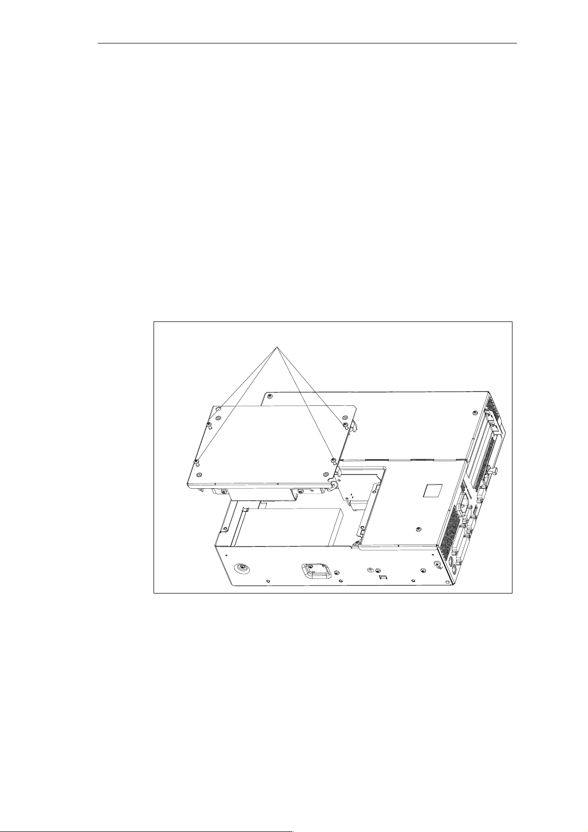
SIMATIC Box PC 620 Expansions
5.5 Removal and Installation of Drives
5.5.1 Removal and Installation of the Hard Disk Drive
1. Undo the 4 screws on the back of the housing.
2. Open the drive holder.
3. Detach the drive holder from the mounting and lay the drive holder with its top
on the housing.
4. Note the cable assignment and pull off the cables.
5. Undo the four screws which secure the hard disk drive to the vibration-damped
part of the mounting. Remove the hard disk drive from the mounting.
6. Proceed in the reverse order to fit the new drive. The new drive must be of the
same type as the one removed.
Fixing screws
Figure 5-13 Installation and Removal of the Drive Holder
5-18
SIMATIC Box PC 620 Manual
C79000-G7076-C639-04
Page 81

Figure 5-14 Hard Disk Drive with Holder Removed
SIMATIC Box PC 620 Expansions
SIMATIC Box PC 620 Manual
C79000-G7076-C639-04
5-19
Page 82
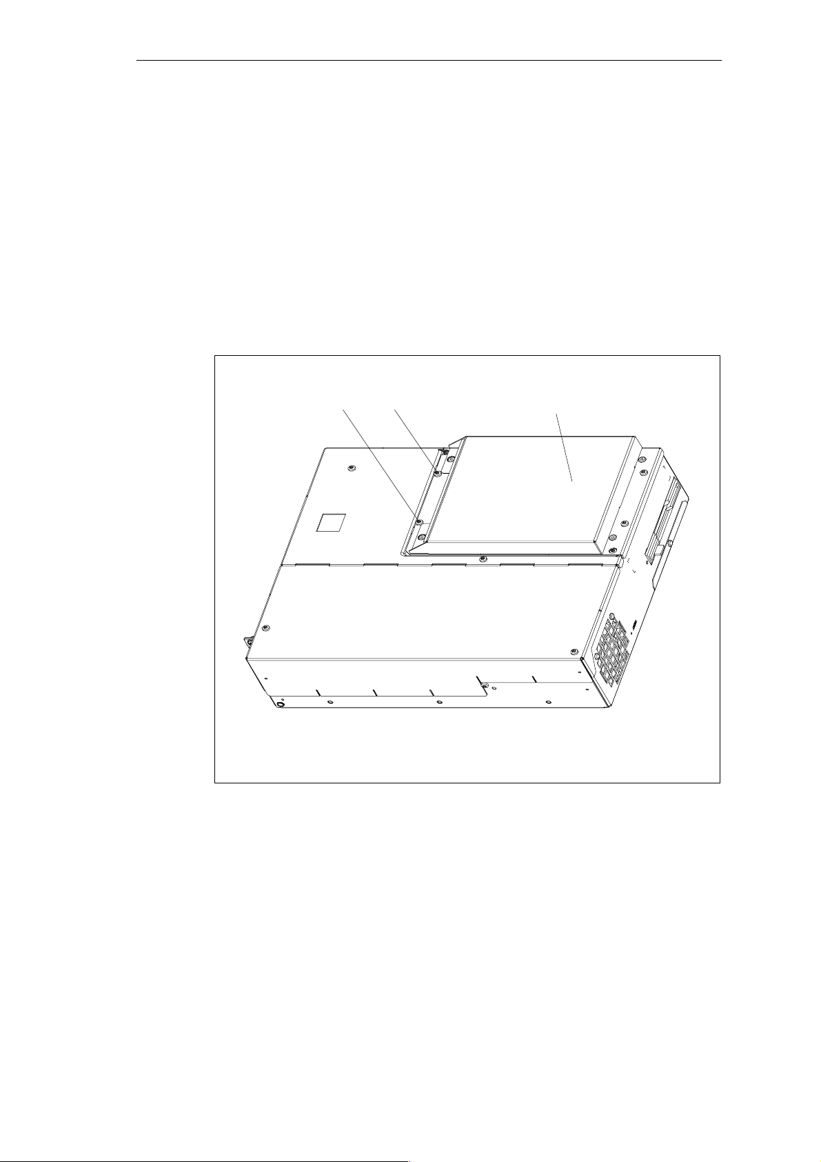
SIMATIC Box PC 620 Expansions
5.5.2 Removal and Installation of a CD-ROM Drive
Depending on the device equipment, a CD-ROM drive is installed in the
SIMATIC Box PC 620.
1. Undo the 2 screws on the back of the housing.
2. Remove the cover of the CD-ROM drive.
3. Undo the three screws which secure the CD-ROM drive to the mounting.
4. Remove the CD-ROM drive from the mounting and carefully pull off the data
cable.
5. Proceed in the reverse order to fit the new drive.
Fixing screws for CD-ROM cover
Figure 5-15 SIMATIC Box PC 620 with CD-ROM Drive
CD-ROM drive with cover
5-20
SIMATIC Box PC 620 Manual
C79000-G7076-C639-04
Page 83
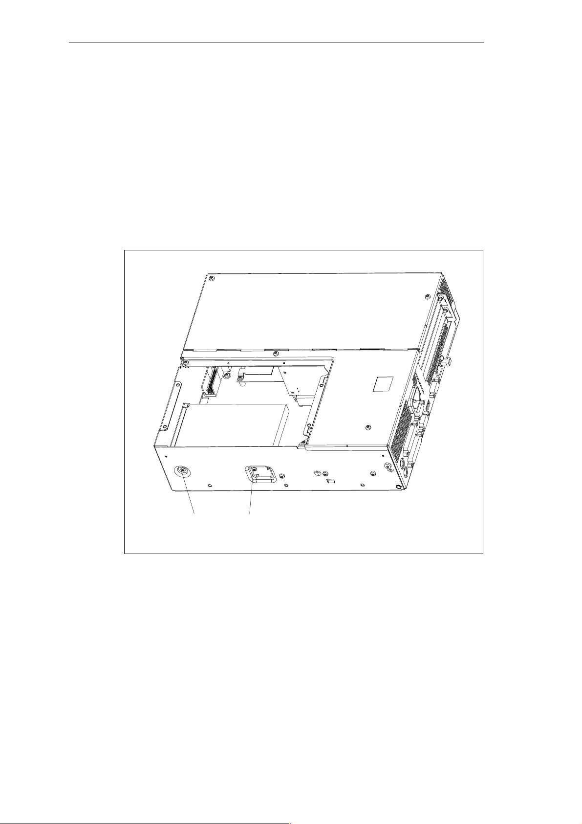
SIMATIC Box PC 620 Expansions
5.5.3 Removal and Installation of the Floppy Drive
1. Open the housing as described in Section 5.1.
2. Remove the drive holder as described in Section 5.5.1.
3. Release the interlock of the controller flex-lead on the motherboard and pull the
flex-lead out of the connector assembly.
4. Undo the two fixing screws (TORX T8) on the housing.
5. Lift the floppy drive upwards out of the housing.
6. Proceed in the reverse order to fit the new drive. The new drive must be of the
same type as the one removed.
Figure 5-16 Installation of the Floppy Disk Drive in the SIMATIC Box PC 620
SIMATIC Box PC 620 Manual
C79000-G7076-C639-04
Fixing screws of the floppy drive
5-21
Page 84
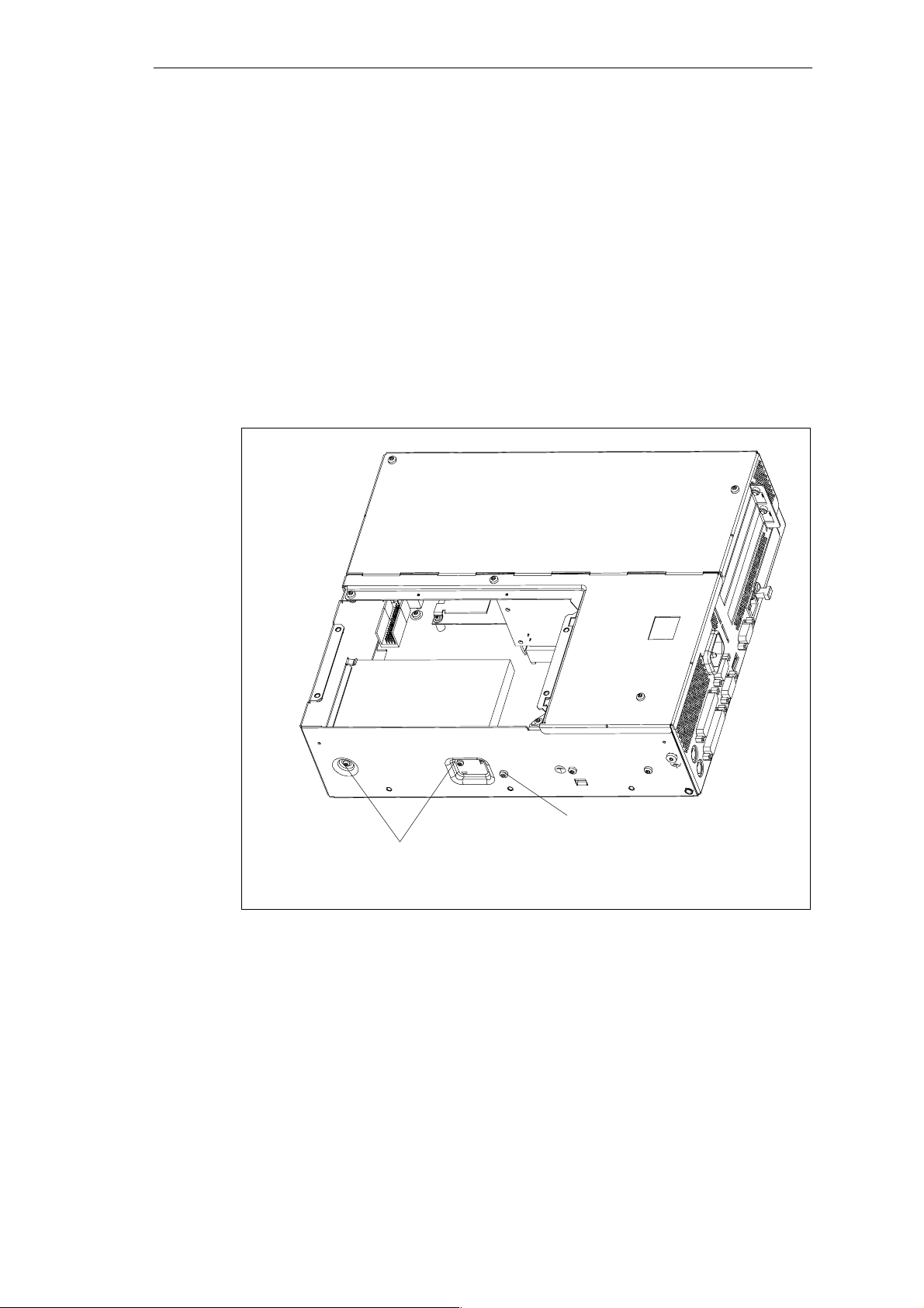
SIMATIC Box PC 620 Expansions
5.5.4 Removal and Installation of the LS 120 Drive
The removal and installation of the LS120 drive takes place with the same steps as
for the floppy drive.
1. Open the housing as described in Section 5.1.
2. Remove the drive holder as described in Section 5.5.1.
3. Release the cable clamp assembly of the controller flex-lead on the
motherboard and pull the flex-lead out of the connector assembly.
4. Undo the two fixing screws (TORX T8) on the housing.
5. Lift the LS 120 drive upwards out of the housing.
6. Proceed in the reverse order to fit the new drive.
5-22
Fixing screws of the LS 120 drive
Figure 5-17 Installation of the LS 120 Drive
Screw for LS 120 cable clamp assembly
SIMATIC Box PC 620 Manual
C79000-G7076-C639-04
Page 85
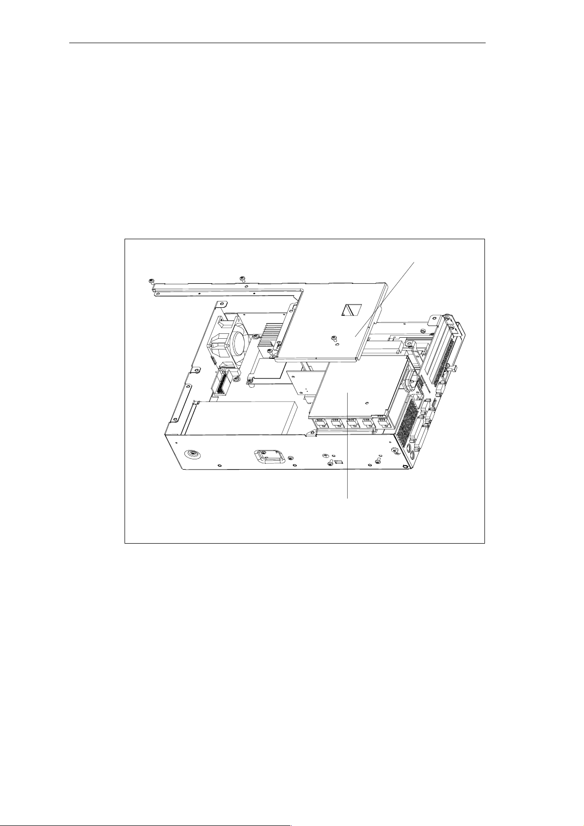
SIMATIC Box PC 620 Expansions
5.6 Removal and Installation of the Power Supply Unit
1. Open the system housing as described in Section 5.1.
2. Remove the drive holder as described in Section 5.5.1.
3. Undo and remove the 3 screws of the cover of the power supply unit from the
housing.
4. Undo the two fixing screws (TORX T10) on the housing.
5. Pull the power supply unit upwards out of the housing.
6. Proceed in the reverse order to fit the new power supply unit.
Cover of the power supply unit
Figure 5-18 Removal and Installation of the Power Supply Unit
SIMATIC Box PC 620 Manual
C79000-G7076-C639-04
Power supply unit
5-23
Page 86
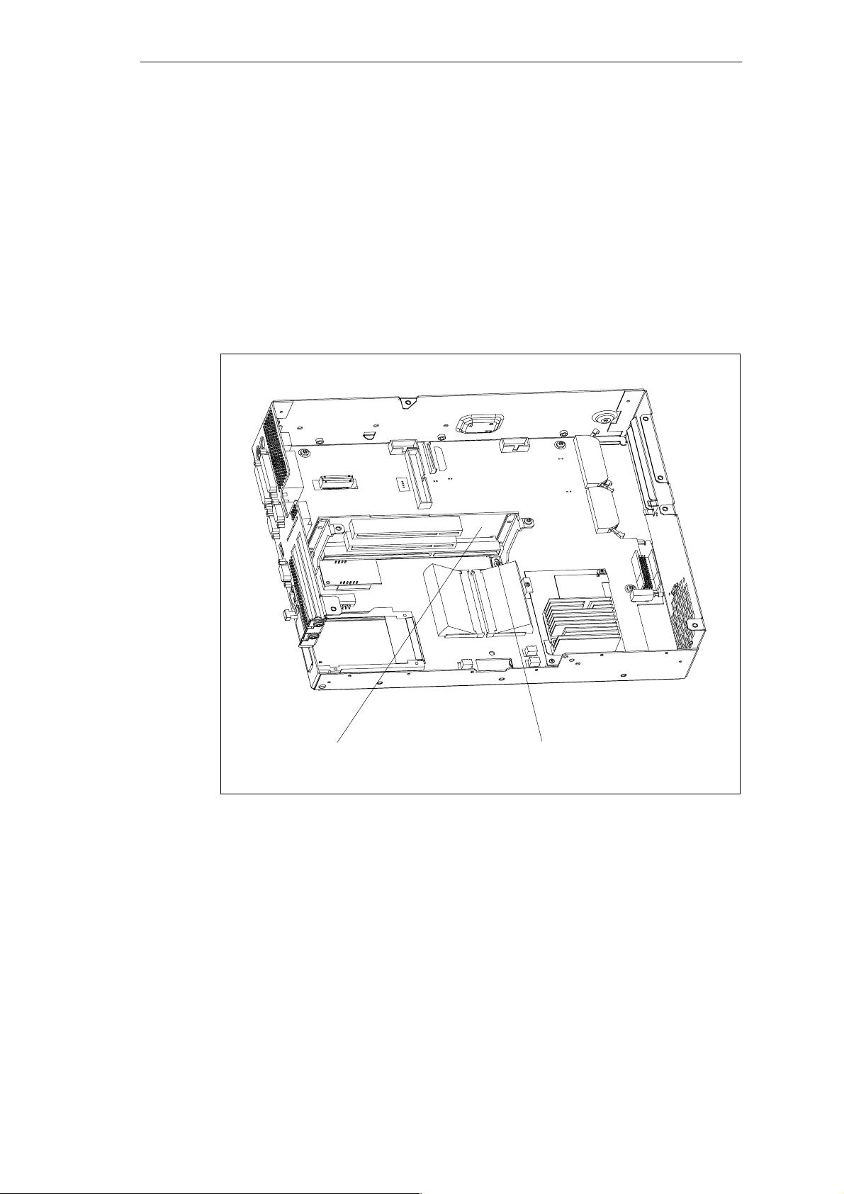
SIMATIC Box PC 620 Expansions
5.7 Removal and Installation of the Bus Board
1. Open the housing as described in Section 5.1.
2. Remove all the modules from the slots (proceed as described in Section 5.4.2.).
3. Remove the drive holder as described in Section 5.5.1.
4. Remove the power supply unit as described in Section 5.6.
5. Undo the screw on the motherboard.
6. Pull the bus board off the motherboard.
7. Proceed in the reverse order to refit the bus board.
5-24
Bus board Fixing screw of the bus board
Figure 5-19 Removal and Installation of the Bus Board
SIMATIC Box PC 620 Manual
C79000-G7076-C639-04
Page 87
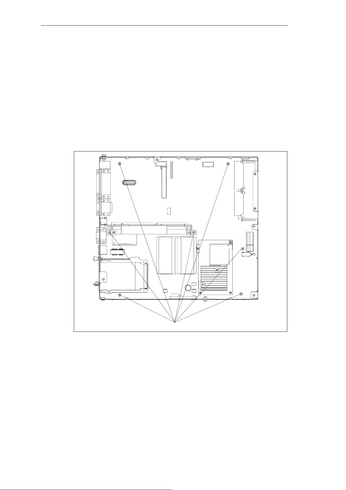
SIMATIC Box PC 620 Expansions
5.7.1 Removal and Installation of the Motherboard
1. Open the housing as described in Section 5.1.
2. Remove all the modules from the slots (proceed as described in Section 5.4.2).
3. Remove the drive holder as described in Section 5.5.1.
4. Remove the power supply unit as described in Section 5.6.
5. Undo the 7 screws on the motherboard and the 10 hexagon head screws on the
ports.
6. Remove the bus board and the motherboard.
7. Proceed in the reverse order to refit the motherboard.
Figure 5-20 Fixing Screws on the Motherboard
The motherboard is available as a replacement part without the processor, memory
modules and bus board .
SIMATIC Box PC 620 Manual
C79000-G7076-C639-04
Fixing screws on the motherboard
5-25
Page 88
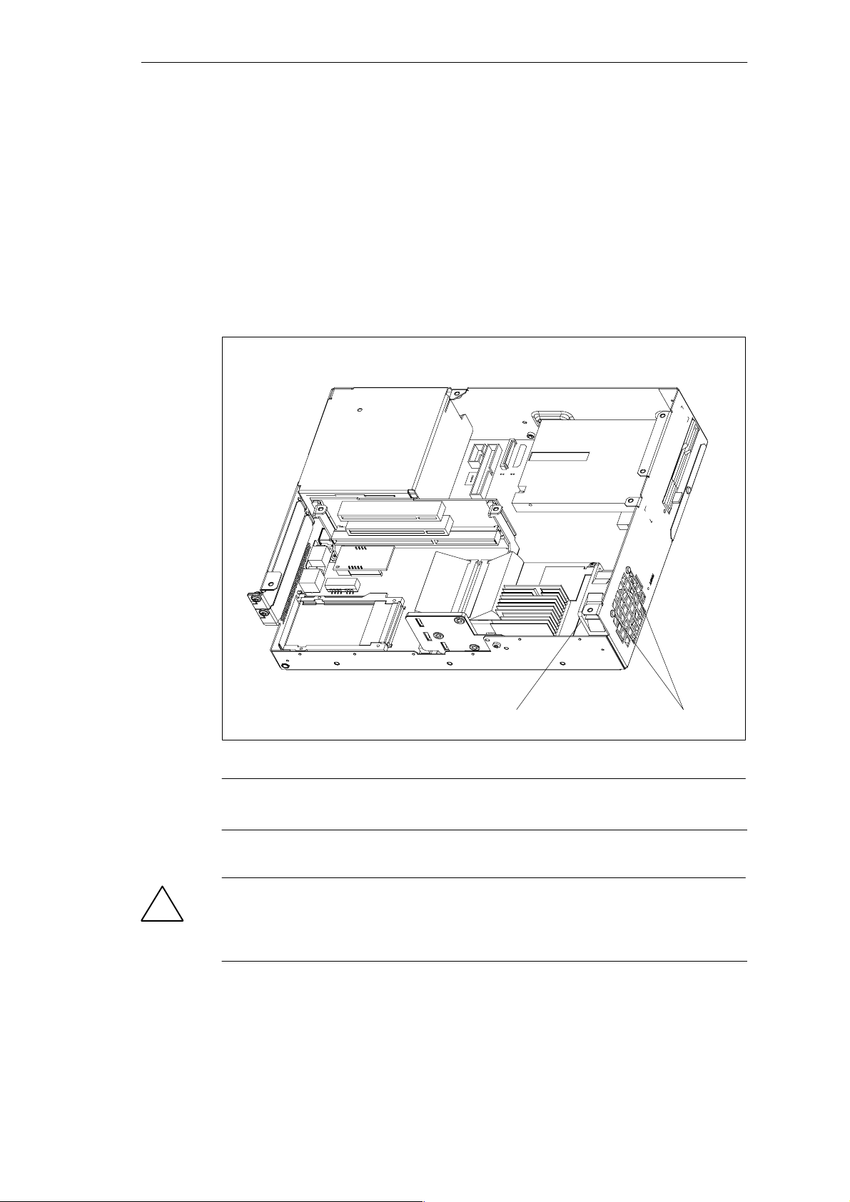
SIMATIC Box PC 620 Expansions
5.8 Removal and Installation of the Fan
The SIMATIC Box PC 620 is cooled by means of a fan which sucks hot air out of
the housing.
1. Open the housing as described in Section 5.1.
2. Pull off the fan cable connector on the basic board.
3. The fan is secured to the housing by two plastic rivets. Undo the rivets by
pressing out the gudgeon from the rear of the rivet shank.
4. Remove the fan.
5. Proceed in the reverse order for assembly.
!
5-26
Fan Plastic rivets
Figure 5-21 Removal and Installation of the Fan
Note
Only a fan of the same type may be fitted!
Caution
To ensure that the device is adequately cooled, take care that the running direction
of the fan is correct when installing.
Ensure that the arrow on the fan points to the housing wall.
SIMATIC Box PC 620 Manual
C79000-G7076-C639-04
Page 89
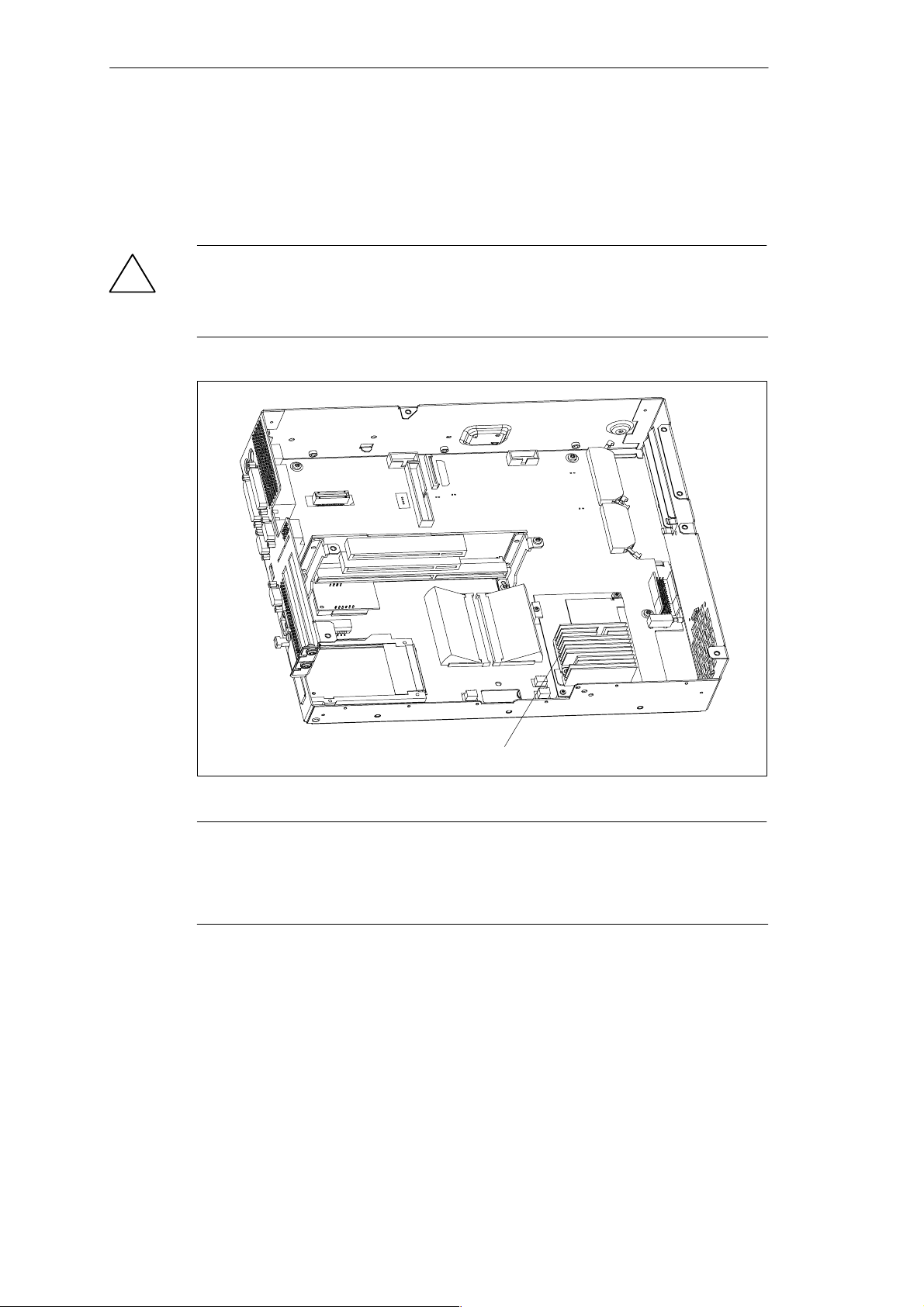
5.9 Processor Upgrade
You can boost the performance of your SIMATIC Box PC 620 by installing other
Celeron or Pentium processors. Consult your local service partner or distributor.
Caution
!
Risk of damage!
Due to differences in processor voltage, motherboards may only be used with
compatible processors.
SIMATIC Box PC 620 Expansions
Processor
Figure 5-22 Position of the Processor
Note
The processor is available as a replacement part without a heat sink.
If an upgrade is implemented, for example to a processor with a different
frequency, it may be important to also upgrade the BIOS.
SIMATIC Box PC 620 Manual
C79000-G7076-C639-04
5-27
Page 90
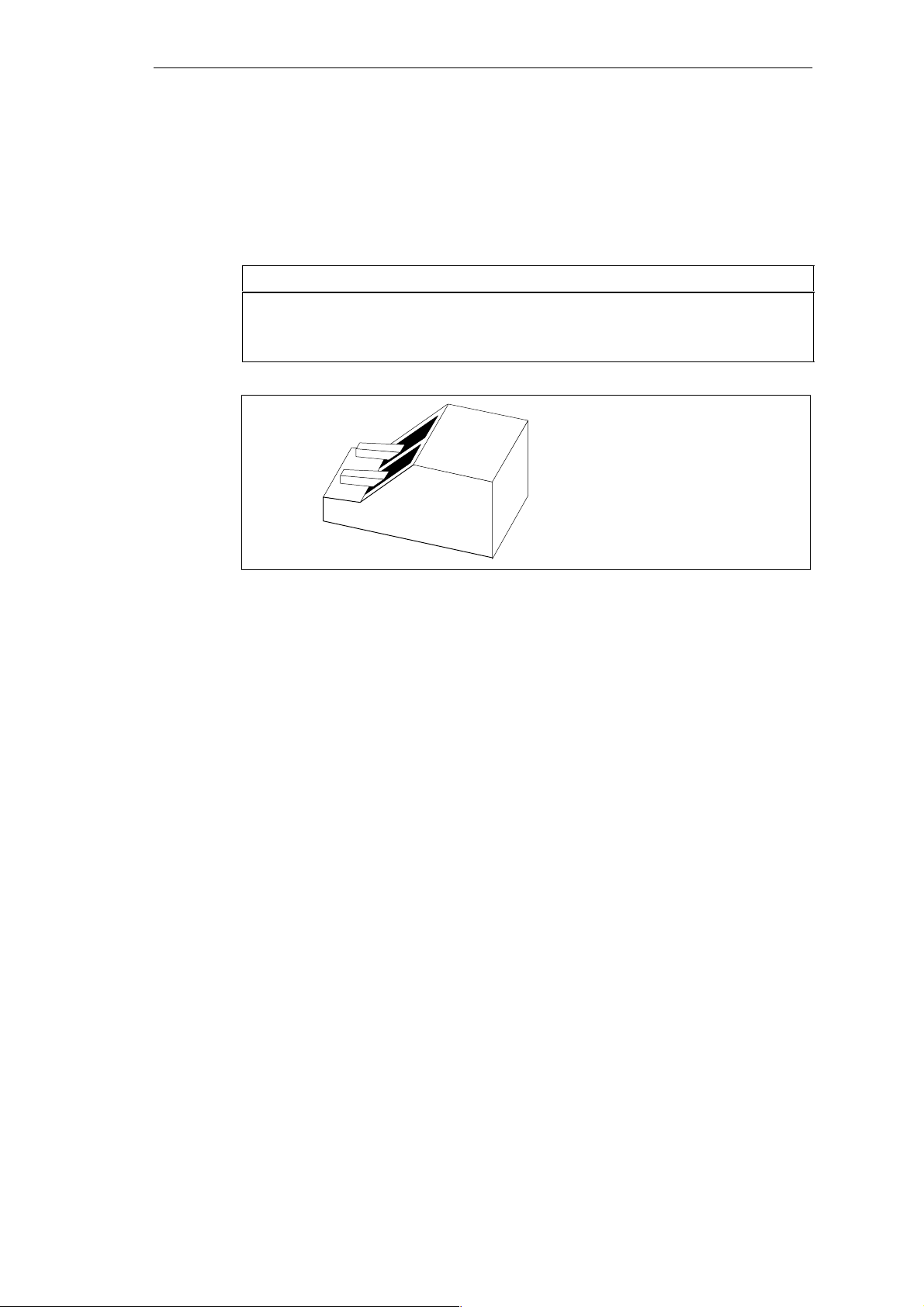
SIMATIC Box PC 620 Expansions
5.10 Switch Settings / Jumpers
TTY Jumpers (S1) *
S1-1 S1-2 Function
on on Active TTY port (standard setting)
on off TTY send loop separate from power source (passive setting)
off on TTY receive loop separate from power source (passive setting)
1
2
off
on
Figure 5-23 Switch Setting TTY Port Active
For TTY operation of the COM1 port, the settings in the setup menu have to be
changed (see Section 6.1.2).
* Not available for the basic variant of the Box PC
5-28
SIMATIC Box PC 620 Manual
C79000-G7076-C639-04
Page 91
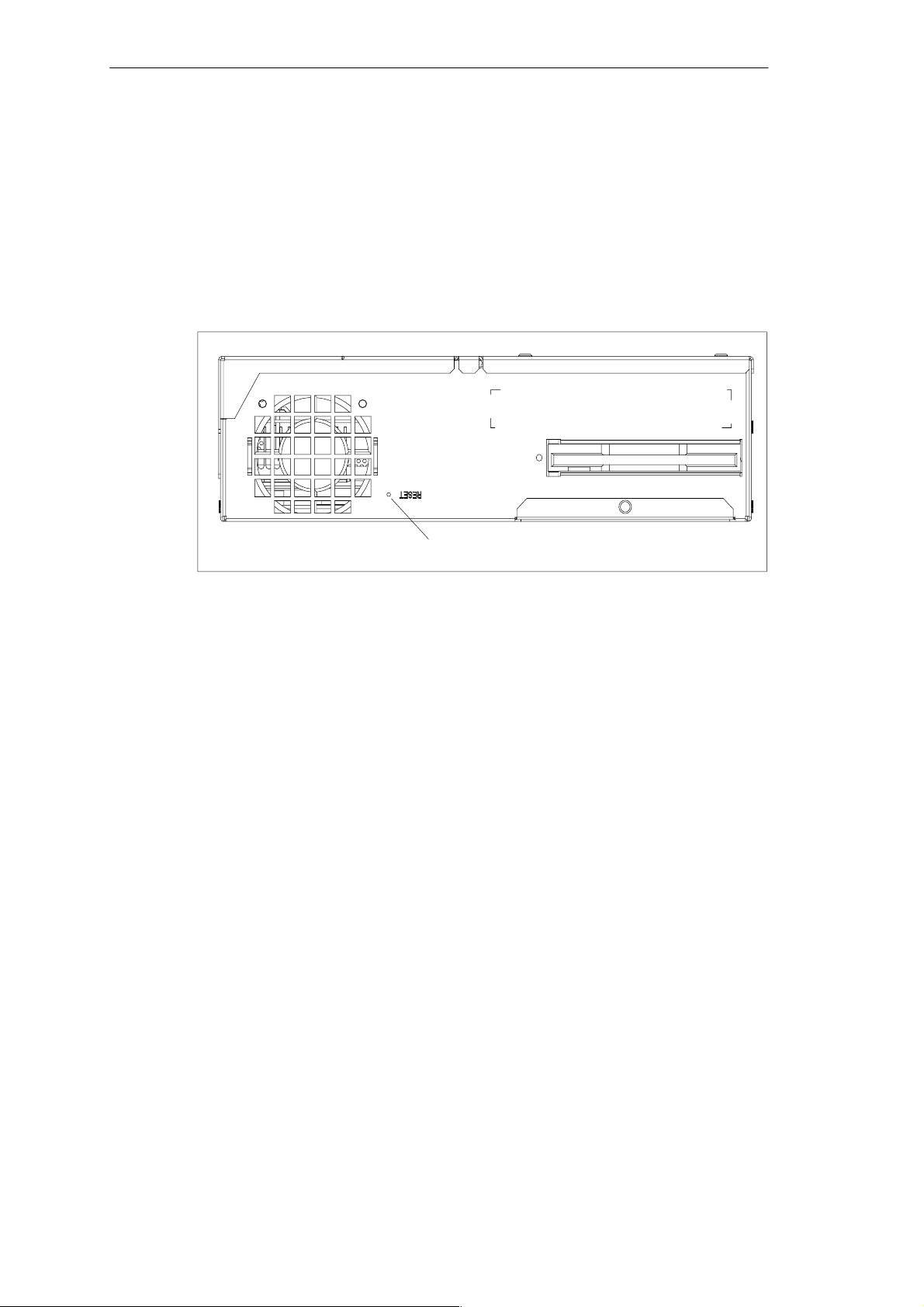
5.11 Reset Button
A hardware reset is initiated by means of the reset button on your device. The PC
is restarted.
In the SIMATIC Box PC 620 the reset button is on the drive side beside the floppy
drive. The reset button can be only actuated with a pointed object (e.g. a ball-point
pen or an opened-up paper clip). The position of the reset button is marked in the
illustration of the SIMATIC Box PC 620 below.
SIMATIC Box PC 620 Expansions
Reset button
Figure 5-24 Reset Button on the SIMATIC Box PC 620
SIMATIC Box PC 620 Manual
C79000-G7076-C639-04
5-29
Page 92

SIMATIC Box PC 620 Expansions
5-30
SIMATIC Box PC 620 Manual
C79000-G7076-C639-04
Page 93

Configuring the S IMATIC Box PC 6 20
What Does This Chapter Contain?
In this chapter, you will learn how to configure your programming device. You need
to do this if you change your system by adding, removing, or exchanging
expansion modules and memory expansions, or by replacing a system module.
Chapter Overview
In chapter you will find on page
6.1 Changing the Device Configuration with SETUP 6-2
6.1.1 The Main Menu 6-5
6.1.2 The Advanced Menu 6-15
6.1.3 The Security Menu 6-22
6.1.4 The Power Menu 6-24
6.1.5 The Boot Sequence Menu 6-26
6.1.6 The Version Menu 6-28
6.1.7 The Exit Menu 6-29
6.1.8 Default Setup Settings 6-30
6.2 Configuring the PCMCIA Interface 6-33
6
SIMATIC Box PC 620 Manual
C79000-G7076-C639-04
6-1
Page 94

Configuring the SIMATIC Box PC 620
6.1 Changing the Device Configuration with SETUP
Changing the Device Configuration
Your SIMATIC Box PC 620 device configuration is set for working with the software
supplied with the unit. You should only change the preset values if you have
modified your Box PC in any way or if a fault occurs when the unit is powered up.
SETUP Program
The SETUP program is in the ROM-BIOS. Information about the system
configuration is stored in the battery-backed RAM of the SIMATIC Box PC 620.
You can use SETUP to set the hardware configuration (for example, hard disk
type) and define the system characteristics. You can also use SETUP to set the
time of day and date.
Incorrect SETUP Data
If incorrect SETUP data are detected when you boot the system, the BIOS
prompts you to
S Start SETUP by pressing F2 or
S Continue booting by pressing F1.
Starting SETUP
On completion of the startup test, the BIOS gives you the opportunity of starting
the SETUP program by displaying the following screen prompt:
PRESS < F2 > to enter SETUP
To start SETUP, proceed as follows:
1. Reset your PG 720 (warm or cold restart).
2. Press the F2 key as long as the BIOS prompt appears on the screen.
SETUP Menus
The various menus and submenus are listed on the following pages. You can get
all the information you need for the SETUP entry selected from the
“Item Specific Help” part of the relevant menu.
6-2
SIMATIC Box PC 620 Manual
C79000-G7076-C639-04
Page 95
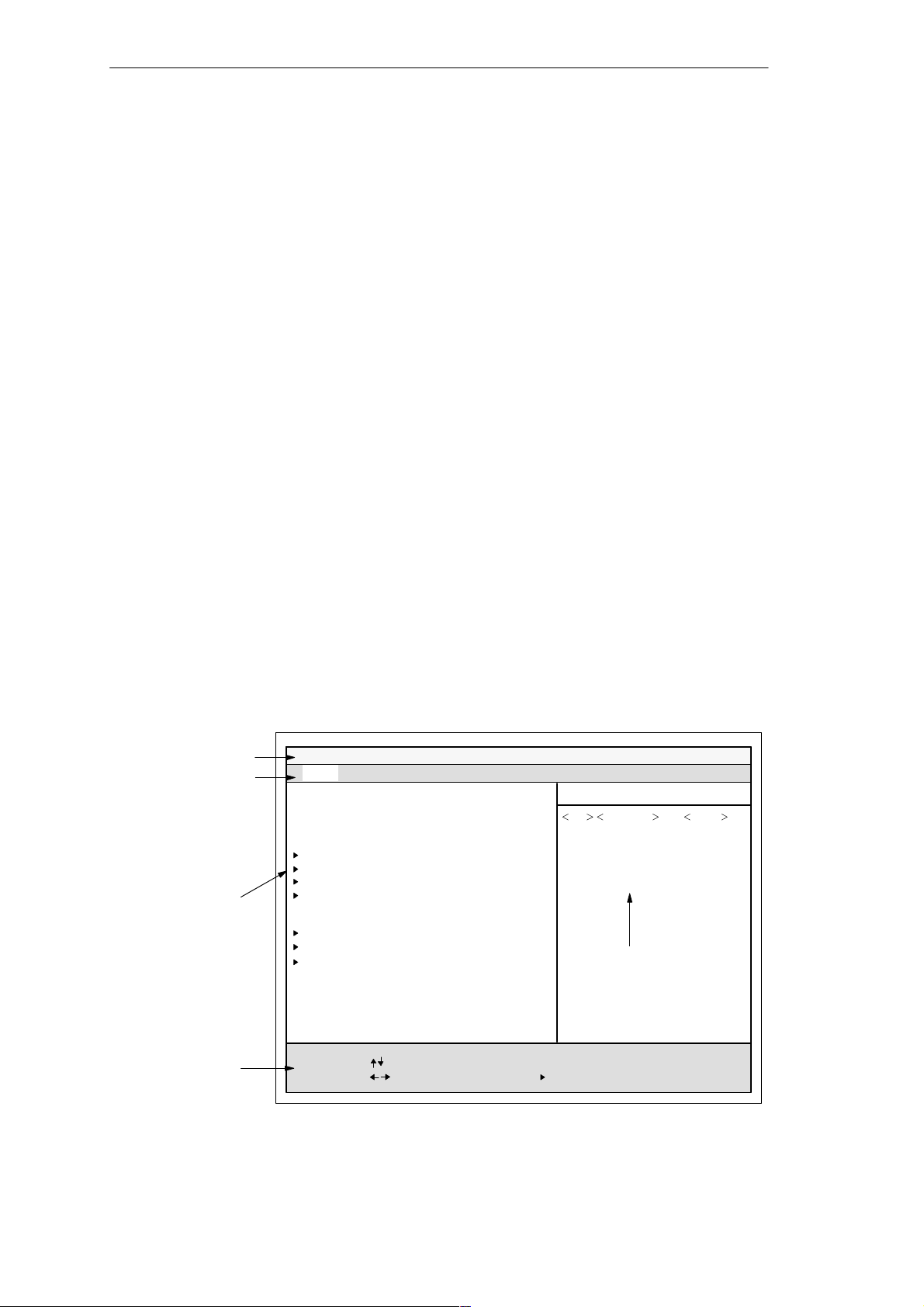
Screen Display Following Power On
With the default setting of your PC, the display shown below appears following
power-on:
Phoenix BIOS 4.0 A5E00016562–ES04
Copyright 1985-98 Phoenix Technologies Ltd.
All Rights Reserved.
SIMATIC Box PC 620 V07.01.04
CPU = PentiumII 266MHz
640K System RAM Passed
63MB Extended RAM Passed
0128K Cache SRAM Passed
System BIOS shadowed
Video BIOS shadowed
UMB upper limit segment address: xxxx
Mouse initialized
Fixed Disk 0: xxxx
ATAPI CD-ROM: Txxx
Press <F2> to enter SETUP
Configuring the SIMATIC Box PC 620
If you press the F2 key while the above display is shown, you select the
ROM-based BIOS setup program. In this program, you can set a number of
system functions and hardware configurations of your programming device.
The default settings are effective on delivery. You can change these settings using
the BIOS setup. The modified settings become effective when you have
saved them and terminated the BIOS setup.
The following screen shots may differ from what is shown here, depending on the
device configuration. The following screen form appears when you start the BIOS
setup:
Header
Menu bar
Selectable
submenu
Main Security Power Exit
System Time:
System Date:
Diskette A:
Primary Master
Primary Slave
Secondary Master
Secondary Slave
Memory Cache:
Boot Options
Keyboard Features
Hardware Options
Advanced
PhoenixBIOS Setup Utility
[ 15:35:32 ]
[ 01/23/1999 ]
[ 1.44 MB, 31/2” ]
[4326 MB]
[None]
[None]
[None]
[Write Back]
Boot Sequence Version
Item Specific Help
Shift-Tab Enter, or
Tab
selects field.
Example:
Hour/Minute/Second
Month/Day/Year
Help window
Operation line
Figure 6-1 SETUP Main Menu
SIMATIC Box PC 620 Manual
C79000-G7076-C639-04
System Memory:
Extended Memory:
F1 Help
ESC Exit
Select Item
Select Menu
640 KB
64512 KB
+ / –
Enter Select
Change Values
Sub-MenuF9F10
Setup Defaults
Save and Exit
6-3
Page 96

Configuring the SIMATIC Box PC 620
Menu Structure
The screen is divided into four sections. In the top section, you can select the
menu screens [Main], [Advanced], [Security], [Po we r ] , [ B o o t Sequenc e],
[Ve rsi o n ], [Exit]. In the left of the center section you can select various settings or
submenus. Brief help texts appear on the right for the currently selected menu
entry. The bottom section contains information for operator inputs.
Yellow stars to the left of the interface designation (for example, Internal COM 1)
indicate a resource conflict between the interfaces managed by the BIOS. In this
case you should select the default settings (F9) or eliminate the conflict.
You can move between the menu screens using the cursor keys [←] and [→].
Menu Meaning
Main System functions are set here
Advanced An extended sytem configuration can be set here
Security Security functions are set here, for example a password
Power Power functions can be selected here
Boot Sequence The boot priorities are defined here
Version Information about the programming device’s release status
Exit Used for terminating and saving
6-4
SIMATIC Box PC 620 Manual
C79000-G7076-C639-04
Page 97
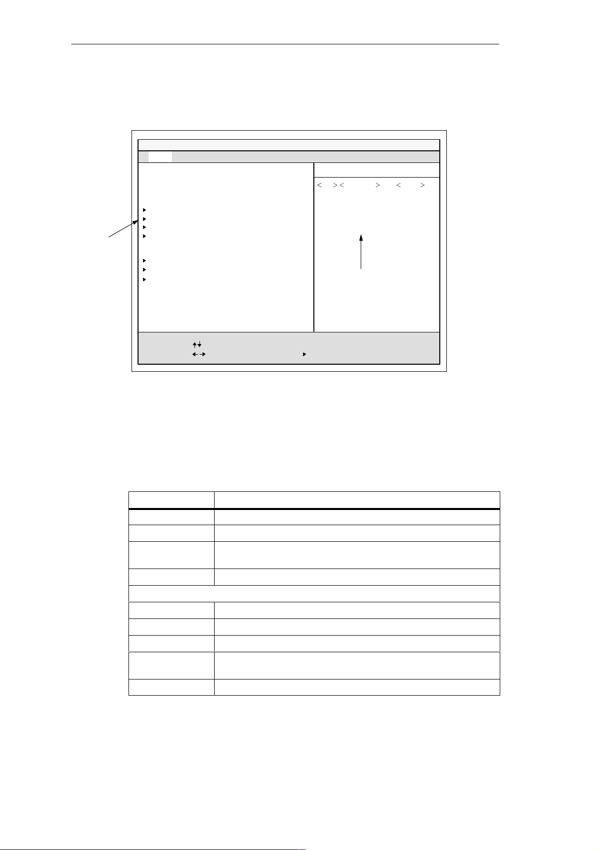
6.1.1 The Main Menu
Advanced
Selectable
submenu
Main Security Power Exit
System Time:
System Date:
Diskette A:
Primary Master
Primary Slave
Secondary Master
Secondary Slave
Memory Cache:
Boot Options
Keyboard Features
Hardware Options
PhoenixBIOS Setup Utility
[ 15:35:32 ]
[ 01/23/1999 ]
[ 1.44 MB, 31/2” ]
[4326 MB]
[None]
[None]
[None]
[Write Back]
Configuring the SIMATIC Box PC 620
Boot Sequence Version
Item Specific Help
Shift-Tab Enter, or
Tab
selects field.
Example:
Hour/Minute/Second
Month/Day/Year
Help window
System Memory:
Extended Memory:
F1 Help
ESC Exit
Figure 6-2 SETUP Main Menu
Setting in the Main Menu
In the Main menu, you can move upwards and downwards using the cursor keys
[↑] and [↓] to select the following system parameters:
Field Meaning
System Time For viewing and setting the current time
System Date For viewing and setting the current date
Diskette A Type of built in floppy disk drive
Memory Cache For setting the cache options
by submenus
Primary Master Type of build in drives
Secondary Master Type of build in drives
Boot Options For setting boot options
Keyboard
Features
Hardware Options For setting hardware options
640 KB
64512 KB
Select Item
Select Menu
+ / –
Change Values
Enter Select
Sub-MenuF9F10
Setup Defaults
Save and Exit
With LS 120 drive [Disabled]
For setting keyboard interface options (e.g. NUM Lock, Typematic
Rate)
SIMATIC Box PC 620 Manual
C79000-G7076-C639-04
6-5
Page 98

Configuring the SIMATIC Box PC 620
System Time und System Date Uhrzeit und Datum
System Time and System Date indicate the current values. Once you have
selected the appropriate option, you can use the [+] and [–] keys to modify the time
setting
Hour:Minute:Second
and the date
Month/Day/Year.
You can move between the entries in the date and time options (for example, from
hour to minute) using the tabulator key.
Diskette A Disk drive
The type of floppy dr ive installed in the PC is set here. The following entries are
possible:
[Disabled] If there is no disk drive or LS 120 drive. Default setting for an installed
LS 120 drive.
[360 KB,5 1/4”]
[1.2 MB,5 1/4”]
[720 KB,3 1/2”]
[1.44 MB, 3 1/2”] Default setting for an installed disk drive A
[2.88 MB, 3 1/2”]
6-6
SIMATIC Box PC 620 Manual
C79000-G7076-C639-04
Page 99
Configuring the SIMATIC Box PC 620
Primary Master Primary Slave Secondary Master/ Secondary Slave
The system jumps to the following submenu when you select this type of menu
field:
PhoenixBIOS Setup Utility
Main
Primary Master [4326MB]
Item Specific Help
“Type” Field
Type:
Cylinders:
Heads:
Total Sectors
Maximum Capacity
Multi-Sector Transfers:
LBA Mode Control:
32 Bit I/O:
Transfer Mode:
Ultra DMA Mode:
F1 Help
ESC Exit
Select Item
Select Menu
[Auto]
[8940]
[ 15]
[8448300]
4326MB
[16 Sectors]
[Enabled]
[Enabled]
[FPIO 4 / DMA 2]
[Disabled]
+ / –
Change Values F9
Enter Select
[AUTO] (recommended)
Autotypes installed
IDE-devices
[USER]
Enter parameters of
IDE-devices installed
at this connection
Sub-Menu
F10
Setup Defaults
Save and Exit
Figure 6-3Primary Master
The parameters you can select here are usually stored on the IDE drive. The ’Auto’
setting in the ’Type’ field means that these values are automatically read from the
drive and written into memory (Autodetect).
If Type is selected for a drive that cannot be detected, a timer times out in
approximately 1 minute and the entries remain unchanged. You should always
check that the interfaces for which you select ’Auto’ are in fact connected to drives.
Select “User” if you want to define the hard-disk type yourself, in which case
remember that you also have to set the other fields, including Cylinder, Heads,
Sectors/Track and WritePrecomp, to the correct values for the type of hard disk in
question.
SIMATIC Box PC 620 Manual
C79000-G7076-C639-04
6-7
Page 100

Configuring the SIMATIC Box PC 620
“Multi Sector-Transfer” Field
The entry in the Multi-Sector Transfer field defines the number of sectors
transferred per interrupt. The value depends on the drive and should be set only by
setting the Type field to Auto.
Disabled
2,4,8,16 sectors
“LBA Mode Control” field
If the LBA Mode Control field (enabled,disabled) is set to ’Enabled’, the system
supports hard disks with capacities greater than 528 Mbytes. The value depends
on the drive and should be set only by setting the Type field to Auto.
“32 Bit-IO” Field
The setting in the 32 Bit I/O field defines the mode of access for the drive
Disabled 16-Bit access
Enabled 32-Bit access (default)
“Transfer Mode” and “Ultra DMA Mode” Fields
The settings in these fields define the interface’s data-transfer rate. The value
depends on the drive and should be set only by setting the Type field to Auto.
Hit ESC to exit the submenu.
6-8
SIMATIC Box PC 620 Manual
C79000-G7076-C639-04
 Loading...