

Siemens SIMATIC 6ES7134-4FB01-0AB0 User Manual
SIMATIC ET 200S distributed I/O 2AI U ST analog electronic module (6ES7134-4FB01-0AB0)
_
_____________
_
_____________
_
_____________
_
_____________
_
_____________
Preface
Properties
1
Parameters
2
Diagnostics
3
Analog value representation
4
Connecting
5
SIMATIC
ET 200S distributed I/O
2AI U ST analog electronic module
(6ES7134-4FB01-0AB0)
Manual
04/2007
A5E01076000-01
Safety Guidelines
Safety Guidelines
This manual contains notices you have to observe in order to ensure your personal safety, as well as to prevent
damage to property. The notices referring to your personal safety are highlighted in the manual by a safety alert
symbol, notices referring only to property damage have no safety alert symbol. These notices shown below are
graded according to the degree of danger.
DANGER
indicates that death or severe personal injury will result if proper precautions are not taken.
WARNING
indicates that death or severe personal injury may result if proper precautions are not taken.
CAUTION
with a safety alert symbol, indicates that minor personal injury can result if proper precautions are not taken.
CAUTION
without a safety alert symbol, indicates that property damage can result if proper precautions are not taken.
NOTICE
indicates that an unintended result or situation can occur if the corresponding information is not taken into
account.
If more than one degree of danger is present, the warning notice representing the highest degree of danger will
be used. A notice warning of injury to persons with a safety alert symbol may also include a warning relating to
property damage.
Qualified Personnel
The device/system may only be set up and used in conjunction with this documentation. Commissioning and
operation of a device/system may only be performed by qualified personnel. Within the context of the safety notes
in this documentation qualified persons are defined as persons who are authorized to commission, ground and
label devices, systems and circuits in accordance with established safety practices and standards.
Prescribed Usage
Note the following:
WARNING
This device may only be used for the applications described in the catalog or the technical description and only
in connection with devices or components from other manufacturers which have been approved or
recommended by Siemens. Correct, reliable operation of the product requires proper transport, storage,
positioning and assembly as well as careful operation and maintenance.
Trademarks
All names identified by ® are registered trademarks of the Siemens AG. The remaining trademarks in this
publication may be trademarks whose use by third parties for their own purposes could violate the rights of the
owner.
Disclaimer of Liability
We have reviewed the contents of this publication to ensure consistency with the hardware and software
described. Since variance cannot be precluded entirely, we cannot guarantee full consistency. However, the
information in this publication is reviewed regularly and any necessary corrections are included in subsequent
editions.
Siemens AG
Automation and Drives
Postfach 48 48
90327 NÜRNBERG
GERMANY
Ordernumber: A5E01076000-01
Ⓟ 09/2007
Copyright © Siemens AG 2007.
Technical data subject to change

2AI U ST analog electronic module (6ES7134-4FB01-0AB0)
Manual, 04/2007, A5E01076000-01
3
Preface
Purpose of the manual
This manual supplements the
ET 200S Distributed I/O System
Operating Instructions.
General functions for the ET 200S are described in the
ET 200S Distributed I/O System
Operating Instructions.
The information in this document along with the operating instructions enables you to
commission the ET 200S.
Basic knowledge requirements
To understand these operating instructions you should have general knowledge of
automation engineering.
Scope of the manual
This manual applies to this ET 200S module. It describes the components that are valid at
the time of publication.
Recycling and disposal
Thanks to the fact that it is low in contaminants, this ET 200S module is recyclable. For
environmentally compliant recycling and disposal of your electronic waste, please contact a
company certified for the disposal of electronic waste.
Additional support
If you have any questions relating to the products described in these operating instructions,
and do not find the answers in this document, please contact your local Siemens
representative.
http://www.siemens.com/automation/partner
The portal to our technical documentation for the various SIMATIC products and systems is
available at:
http://www.siemens.com/automation/simatic/portal
The online catalog and ordering system are available at:
http://www.siemens.com/automation/mall

Preface
2AI U ST analog electronic module (6ES7134-4FB01-0AB0)
4 Manual, 04/2007, A5E01076000-01
Training center
We offer courses to help you get started with the ET 200S and the SIMATIC S7 automation
system. Please contact your regional training center or the central training center in D 90327, Nuremberg, Germany.
Phone: +49 (911) 895-3200.
http://www.siemens.com/sitrain
Technical Support
You can reach technical support for all A&D projects
● using the support request web form:
http://www.siemens.com/automation/support-request
● Phone: + 49 180 5050 222
● Fax: + 49 180 5050 223
For more information about our technical support, refer to our Web site at
http://www.siemens.de/automation/service
Service & Support on the Internet
In addition to our documentation services, you can also make use of our comprehensive
online knowledge base on the Internet.
http://www.siemens.com/automation/service&support
There you will find:
● Our Newsletter, which constantly provides you with the latest information about your
products.
● The right documentation for you using our Service & Support search engine.
● The bulletin board, a worldwide knowledge exchange for users and experts.
● Your local contact for Automation & Drives in our contact database.
● Information about on-site services, repairs, spare parts. Lots more can be found on our
"Services" pages.

2AI U ST analog electronic module (6ES7134-4FB01-0AB0)
Manual, 04/2007, A5E01076000-01
5
Table of contents
Preface ...................................................................................................................................................... 3
1 Properties ..................................................................................................................................................
7
1.1 2AI U ST analog electronic module (6ES7134-4FB01-0AB0) .......................................................
7
2 Parameters..............................................................................................................................................
11
2.1 Parameters...................................................................................................................................
11
2.2 Parameter description..................................................................................................................
12
3 Diagnostics..............................................................................................................................................
13
3.1 Diagnostics using LED display.....................................................................................................
13
3.2 Error types....................................................................................................................................
14
4 Analog value representation....................................................................................................................
15
4.1 Introduction ..................................................................................................................................
15
4.2 Analog value representation for measuring range with SIMATIC S7 ..........................................
15
4.3 Measuring ranges ........................................................................................................................
16
4.4 Effect on analog value representation .........................................................................................
18
4.4.1 Effect of the supply voltage and the operating state on analog input values ..............................
18
4.4.2 Effect of the value range on the 2AI U ST analog input ..............................................................
18
5 Connecting ..............................................................................................................................................
19
5.1 Connecting measuring sensors ...................................................................................................
19
5.2 Wiring unused channels of the analog input modules .................................................................
22
5.3 Using the shield connection .........................................................................................................
22
Index........................................................................................................................................................
23

Table of contents
2AI U ST analog electronic module (6ES7134-4FB01-0AB0)
6 Manual, 04/2007, A5E01076000-01
2AI U ST analog electronic module (6ES7134-4FB01-0AB0)
Manual, 04/2007, A5E01076000-01
7
Properties
1
1.1 2AI U ST analog electronic module (6ES7134-4FB01-0AB0)
Properties
● 2 inputs for measuring voltage
● Input ranges:
± 10 V, resolution 13 bits + sign
± 5 V, resolution 13 bits + sign
1 V to 5 V, resolution 13 bits
● Isolated from the load voltage L+
● Permissible common mode voltage 2 VAC
SS
● Extended temperature range from 0 to 50°C with vertical installation
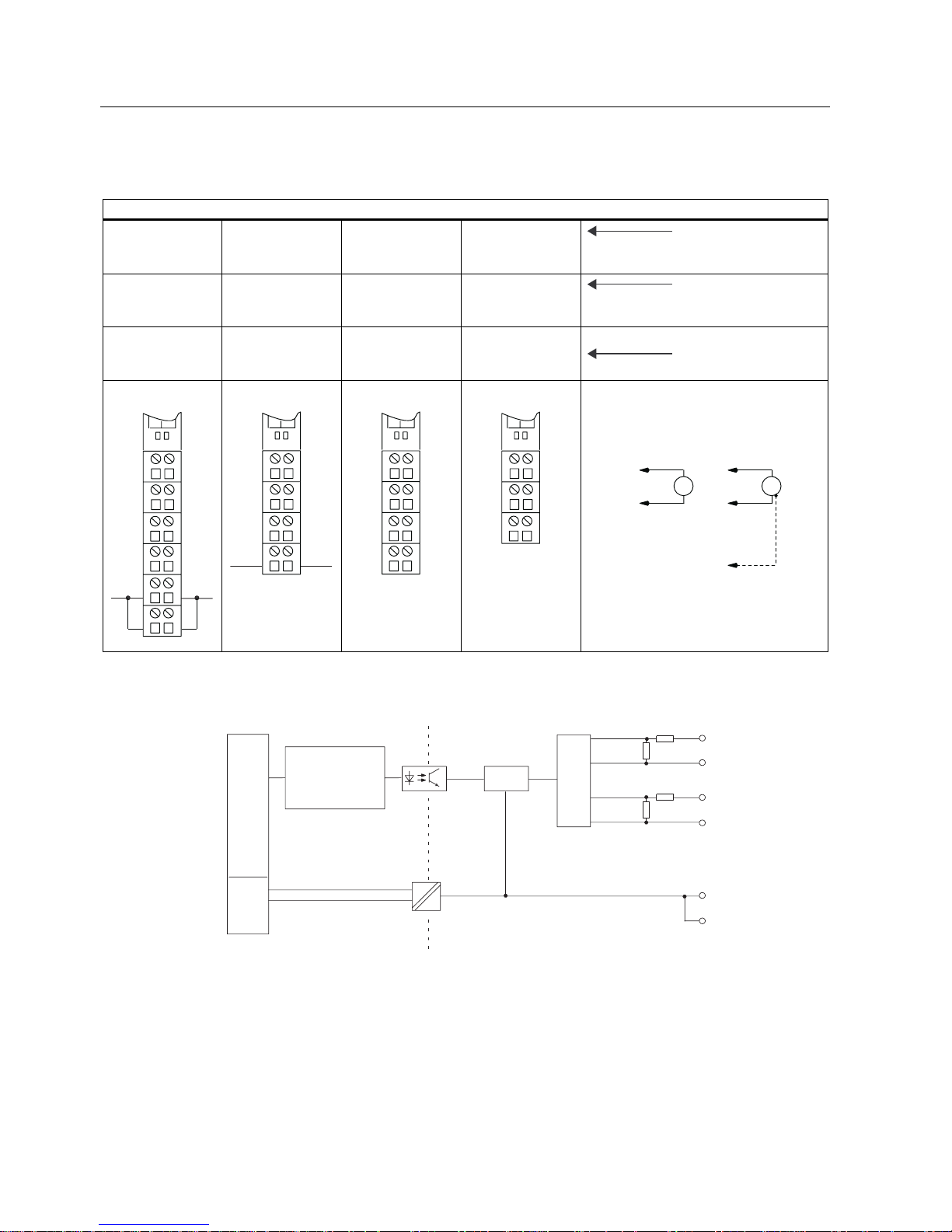
General terminal assignment
Note
Terminals 4, 8, A4, A8, A3 and A7 are only available at specified terminal modules.
Terminal assignment for 2AI U ST (6ES7134-4FB01-0AB0)
Terminal Assignment Terminal Assignment Notes
1 M
0+
5 M
1+
2 M
0-
6 M
1-
3 M
ana
7 M
ana
4 n.c. 8 n.c.
A4 AUX1 A8 AUX1
A3 AUX1 A7 AUX1
• M
n+
: Input signal "+", channel n
• M
n-
: Input signal "-", channel n
• M
ana
: Ground of the module
• n.c.: Not connected (max. 30 V DC can be connected)
• AUX1: Protective-conductor terminal or potential bus (freely usable
up to 230 VAC)
Properties
1.1 2AI U ST analog electronic module (6ES7134-4FB01-0AB0)
2AI U ST analog electronic module (6ES7134-4FB01-0AB0)
8 Manual, 04/2007, A5E01076000-01
Usable terminal modules
Usable terminal modules for 2AI U ST (6ES7134-4FB01-0AB0)
TM-E15C26-A1
(6ES7193-4CA500AA0)
TM-E15C24-A1
(6ES7193-4CA300AA0)
TM-E15C24-01
(6ES7193-4CB300AA0)
TM-E15C23-01
(6ES7193-4CB100AA0)
Spring terminal
TM-E15S26-A1
(6ES7193-4CA400AA0)
TM-E15S24-A1
(6ES7193-4CA200AA0)
TM-E15S24-01
(6ES7193-4CB200AA0)
TM-E15S23-01
(6ES7193-4CB000AA0)
Screw-type terminal
TM-E15N26-A1
(6ES7193-4CA800AA0)
TM-E15N24-A1
(6ES7193-4CA700AA0)
TM-E15N24-01
(6ES7193-4CB700AA0)
TM-E15N23-01
(6ES7193-4CB600AA0)
Fast Connect
$
$8;
$
$
$
$8;
$$
99
0
0
0
3($8;
0
:LULQJH[DPSOHV
Block diagram
$'8
0
$1$
9
/
0
08;
3
3
%DFNSODQHEXV
(76
EDFNSODQHEXV
LQWHUIDFH
FRQQHFWLRQ
Figure 1-1 Block diagram of the 2AI U ST
 Loading...