

Siemens SIMATIC 577 Operating Instructions Manual

Operating Instructions
(compact)
1
SIMATIC
Industrial PC
SIMATIC Panel PC 577
Operating Instructions (compact)
Release 04/2006
A5E00795255
Safety Guidelines
This manual contains notices you have to observe in order to ensure your personal safety, as well as to prevent
damage to property. The notices referring to your personal safety are highlighted in the manual by a safety alert
symbol, notices referring only to property damage have no safety alert symbol. These notices shown below are
graded according to the degree of danger.
Danger
indicates that death or severe personal injury will result if proper precautions are not taken.
Warning
indicates that death or severe personal injury may result if proper precautions are not taken.
Caution
with a safety alert symbol, indicates that minor personal injury can result if proper precautions are not taken.
Caution
without a safety alert symbol, indicates that property damage can result if proper precautions are not taken.
Notice
indicates that an unintended result or situation can occur if the corresponding information is not taken into
account.
If more than one degree of danger is present, the warning notice representing the highest degree of danger will
be used. A notice warning of injury to persons with a safety alert symbol may also include a warning relating to
property damage.
Qualified Personnel
The device/system may only be set up and used in conjunction with this documentation. Commissioning and
operation of a device/system may only be performed by qualified personnel. Within the context of the safety notes
in this documentation qualified persons are defined as persons who are authorized to commission, ground and
label devices, systems and circuits in accordance with established safety practices and standards.
Prescribed Usage
Note the following:
Warning
This device may only be used for the applications described in the catalog or the technical description and only in
connection with devices or components from other manufacturers which have been approved or recommended by
Siemens. Correct, reliable operation of the product requires proper transport, storage, positioning and assembly
as well as careful operation and maintenance.
Trademarks
All names identified by ® are registered trademarks of the Siemens AG. The remaining trademarks in this
publication may be trademarks whose use by third parties for their own purposes could violate the rights of the
owner.
Disclaimer of Liability
We have reviewed the contents of this publication to ensure consistency with the hardware and software
described. Since variance cannot be precluded entirely, we cannot guarantee full consistency. However, the
information in this publication is reviewed regularly and any necessary corrections are included in subsequent
editions.
Siemens AG
Automation and Drives
Postfach 48 48
90437 NÜRNBERG
GERMANY
Order No.: A5E00795255
Edition 04/2006
Copyright © Siemens AG
20052006.
Technical data subject to change
SIMATIC Panel PC 577
Operating Instructions, Release 04/2006, A5E00795255
1-1
Operating Instructions (compact)
1
1.1 Components of the product
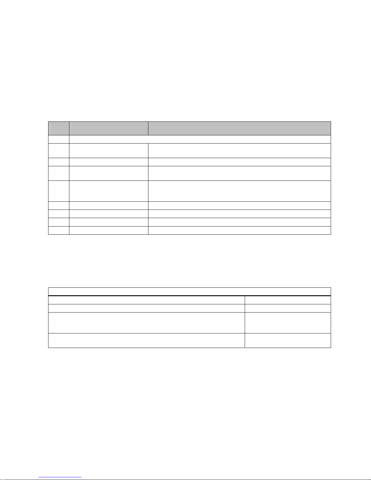
Number Name Description
1 SIMATIC Panel PC 577
1 Restore DVD Contains a hard disk image file with the original software (operating system
with installed hardware drivers).
1 Documentation and Drivers CD Contains the documentation and the hardware drivers.
1 Operating Instructions (compact)
SIMATIC Panel PC 577
Print copy of the Operating Instructions (compact) SIMATIC Panel PC 577
6 / 8 Clamp Mounting bracket for the SIMATIC Panel PC 577.
Device with 12"/15" display: 6 pieces
Device with 19" display: 8 pieces
1 AC power cable Power cable for 110 / 230V AC power supply.
1 Lock for mains connector Lock for AC power cable
1 Card retainer Retainer for mounting PCI modules
1 Paper template Template for preparing the mounting cut-out
1.2 Device identification data
Enter the identification data of the device in the table:
Serial number (on the rating plate)
Order number of the device
For the Windows 2000 / XP Professional variants:
Microsoft Windows Product Key from the "Certificate of Authenticity" (COA).
The COA label is attached to the device
Ethernet address: BIOS setup (F2 key) under Main > Hardware Options > Ethernet
Address
1.3 Product documentation
The detailed operating instructions for Panel PC 577 can be downloaded as a PDF file on
the internet under the following address: http://www4.ad.siemens.de
Operating Instructions (compact)
1.4 Safety instructions
SIMATIC Panel PC 577
1-2 Operating Instructions, Release 04/2006, A5E00795255
1.4 Safety instructions
Caution
In order to avoid substantial damage and for your own safety, note the safety instructions in
this documentation and in the operating instructions.
Warning
Function test while installing the device in machines or execute systems
Following the results of a risk analysis, additional protection equipment on the machine or
the system is necessary to avoid endangering persons. With this, especially the
programming, configuration and wiring of the inserted I/O modules have to be executed, in
accordance with the safety performance (SIL, PL or Cat.) identified by the necessary risk
analysis. The intended use of the device has to be ensured.
The proper use of the device has to be verified with a function test on the system. This test
can detect programming, configuration and wiring errors. The test results have to be
documented and, if necessary, entered into the relevant documents that verify safety.
1.5 Mounting / panel-mounting
1.5.1 Permitted mounting positions
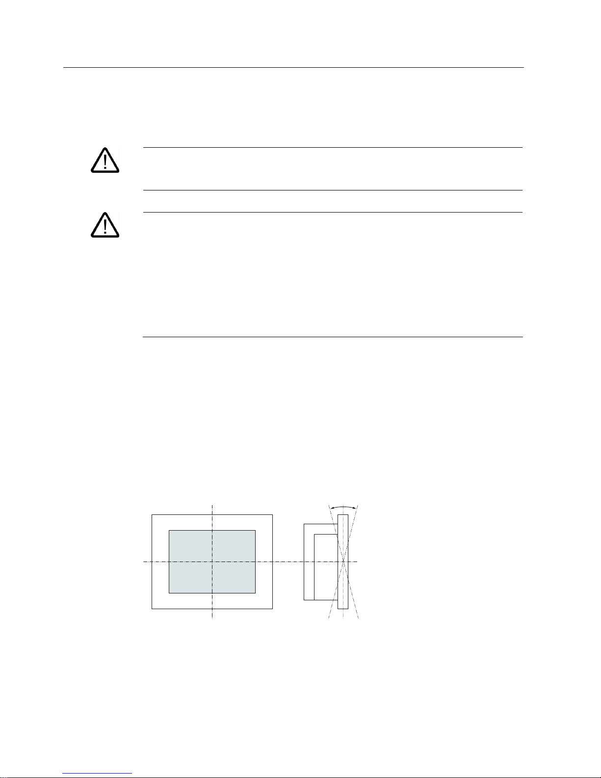
Mounting positions
Only vertical installation with a deviation of up to +5° and -5° in the specified directions is
permitted for the device.
r
r
Figure 1-1 Permitted mounting positions
Operating Instructions (compact)
1.5 Mounting / panel-mounting
SIMATIC Panel PC 577
Operating Instructions, Release 04/2006, A5E00795255
1-3
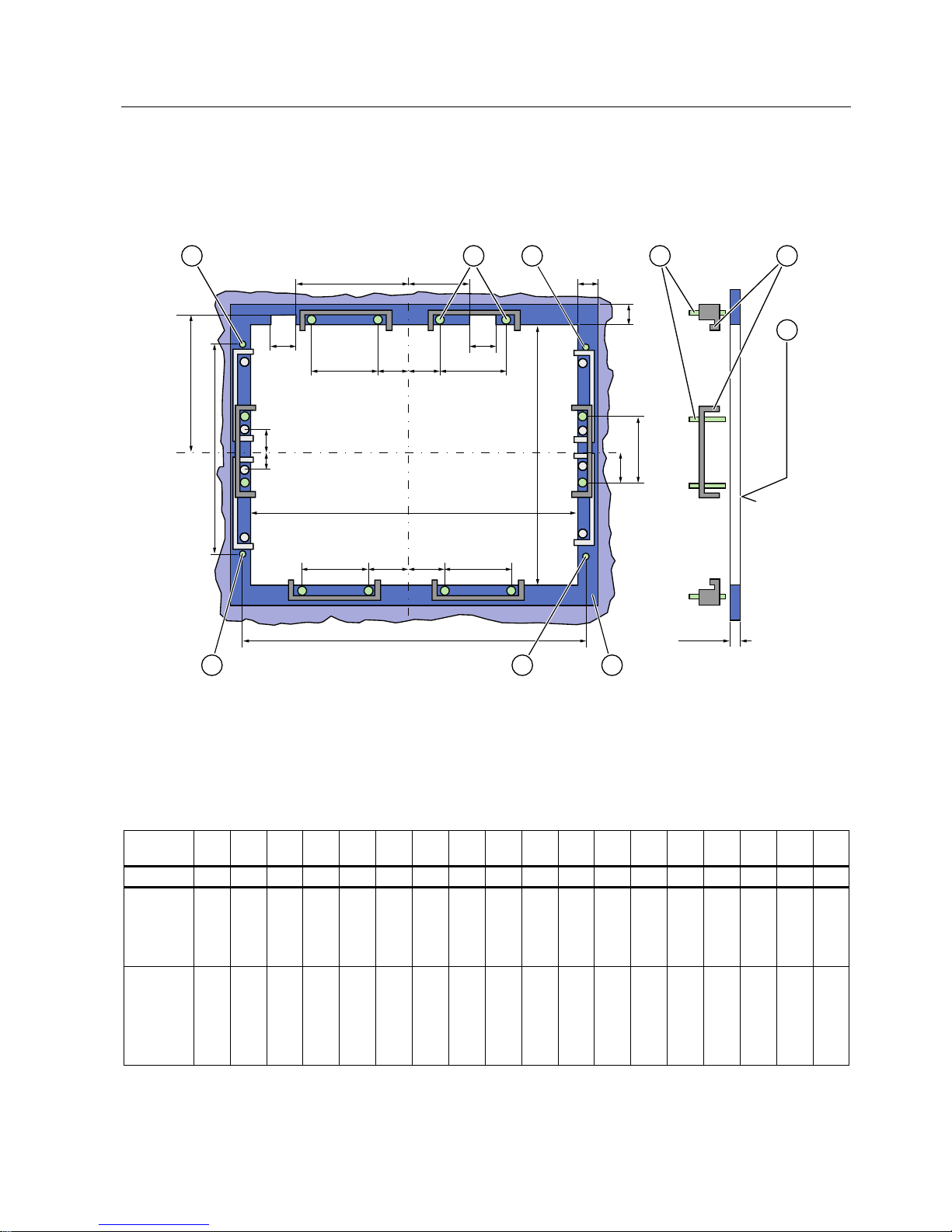
1.5.2 Preparing the mounting cut-out
The following illustration shows the dimensions for the mounting cut-out. You can also obtain
these dimensions from the paper template supplied with the device.
/
/ /
/ 6 6 /
/ 6 6 /
/
/
/
/
$
6
/
/
66
/
$
PP
Figure 1-2 Drill holes for the screws and pressure points for the clamp screws
(1) Drill hole for screw attachment (4) Clamp
(2) Pressure points for clamp (5) R
Z
120 in the seal area
(3) Setscrews (6) Seal area
Table 1-1 Dimensions for the mounting cut-out in mm
Control
unit
L1 L2 L3
1)L4 1)
L5 L6
2)L7 2)L8 2)L9 2)
A1 A2 S1 S2 S3 S4 S53)S63)S7
3)
Tolerance +1 +1 ±0.2 ±0.2 ±0.5 ±0.5 ±0.5 ±0.5 +1 ±1 ±1 ±1 ±1 ±1 ±1 ±1 ±1 ±1
Key panel
12" TFT
15" TFT
450
450
290
321
465
465
235
279
112
112
—
186
—
135
—
25
—
165
16
16
10
17
78
51
78
51
78
51
78
51
56
56
—
—
—
—
Touch
panel
12" TFT
15" TFT
19" TFT
368
450
450
290
290
380
—
465
465
—
235
235
112
112
112
—
—
—
—
—
—
—
—
—
—
—
—
16
16
16
10
10
10
19
81
46
35
81
46
35
81
46
35
81
46
56
56
—
—
—
33
—
—
33
Operating Instructions (compact)
1.5 Mounting / panel-mounting
SIMATIC Panel PC 577
1-4 Operating Instructions, Release 04/2006, A5E00795255
1)
M6 thread or drill holes with a diameter of 7 mm
2)
Cut-outs for the shafts of the insert strips are only necessary for 15" key panels.
3)
Only for 19" touch panels are two clamps necessary for vertically securing clamps.
Preparing the mounting cut-out
Steps for preparing the mounting cut-out
1 Select a location suitable for mounting, taking into account the mounting position.
2 On the basis of the dimensions, check whether the required screw and pressure points on the
rear and the seal area are easily accessible after the completion of the mounting cut-out.
Otherwise the mounting cut-out is useless.
3 Complete the mounting cut-out in accordance with the dimensions. Use the paper template
supplied with the device for this purpose.
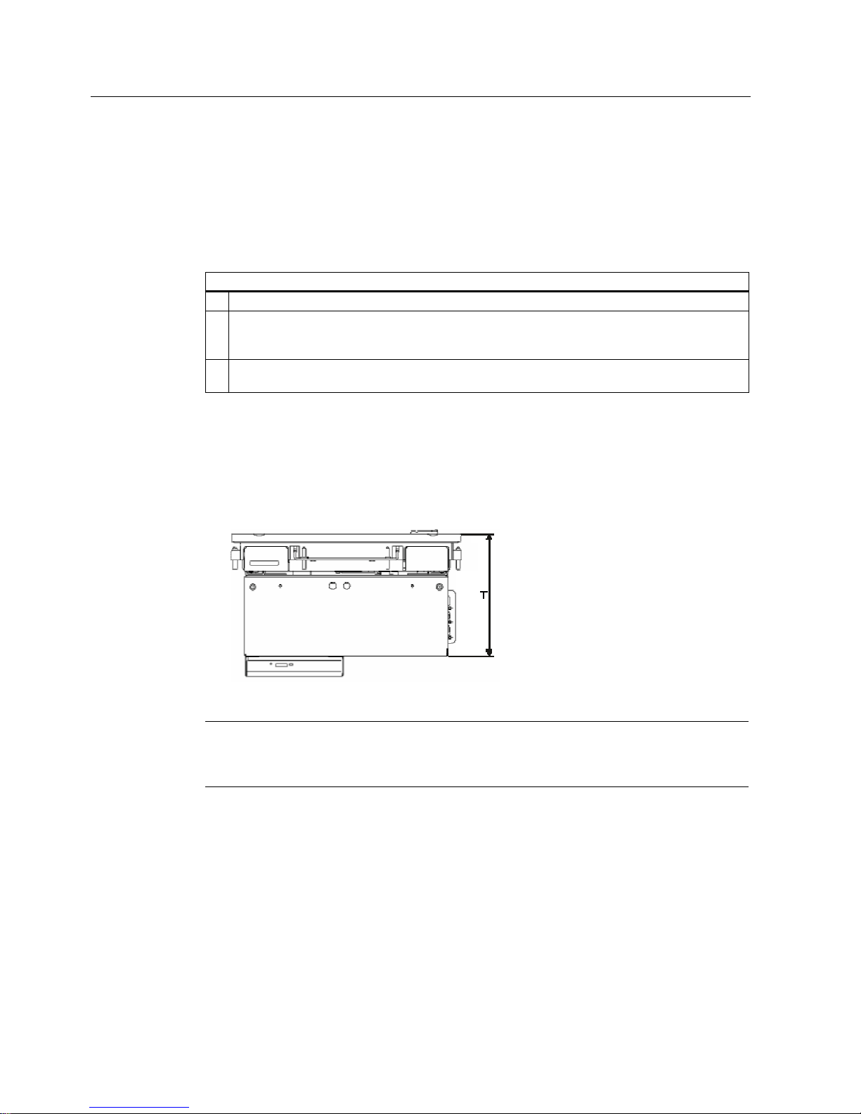
1.5.3 Mounting depth of the device
Control unit T
Key panel with 12" TFT 147 mm
Key panel with 15" TFT 172 mm
Touch panel with
12" TFT
162 mm
Touch panel with
15" TFT
166 mm
Touch panel with
19" TFT
182 mm
Note
Additional mounting depth with DVD drive
The device depth increases by 28 mm when a DVD drive is installed in the device.
Operating Instructions (compact)
1.5 Mounting / panel-mounting
SIMATIC Panel PC 577
Operating Instructions, Release 04/2006, A5E00795255
1-5
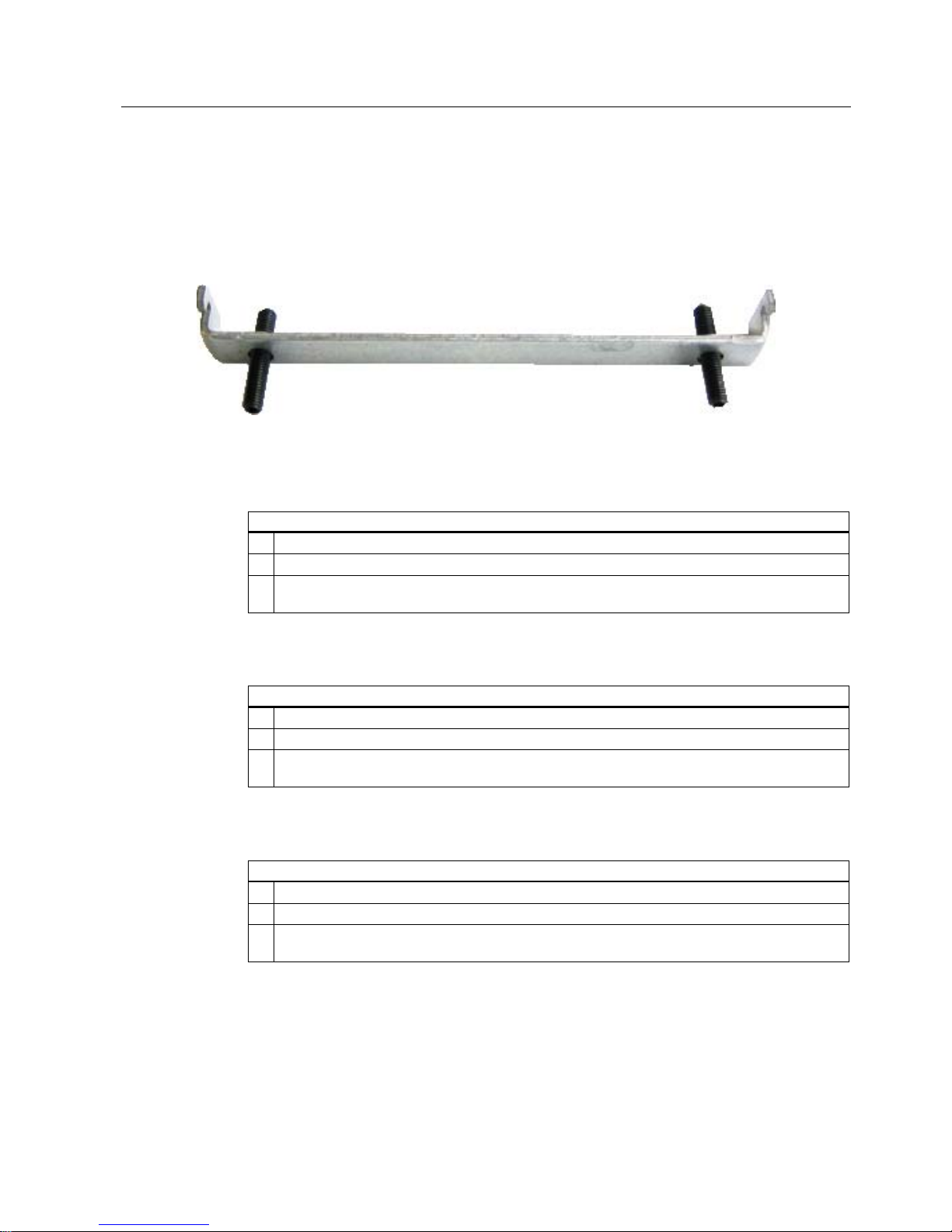
1.5.4 Securing the device with clamps
You require 6 clamps in order to mount the device with a 12"/15" display. A device with a 19"
display must be mounted with 8 clamps. The required number of clamps is included in your
Panel PC delivery package.
Required tool for fastening the clamps: Allen wrench 2.5 mm
Figure 1-3 Clamp assembly
Rack installation
Steps for securing the device with clamps
1 Disconnect the device from the power supply.
2 Working from the front, insert the device into the 19" rack.
3 Fasten the control unit in the rack from the rear using the clamps. Tighten the setscrews to a
torque of 0.4-0.5 Nm.
Swivel arm installation
Steps for securing the device with clamps
1 Disconnect the device from the power supply.
2 Working from the front, place the device onto the swivel arm.
3 Fasten the control unit on the swivel arm from the rear using the clamps. Tighten the setscrews
to a torque of 0.4-0.5 Nm.
Control cabinet installation
Steps for securing the device with clamps
1 Disconnect the device from the power supply.
2 Working from the front, insert the device into the mounting cut-out.
3 Secure the control unit in the mounting cut-out from behind with the clamps, as shown in the
mounting cut-out in the dimensions. Tighten the setscrews to a torque of 0.4-0.5 Nm.

Operating Instructions (compact)
1.5 Mounting / panel-mounting
SIMATIC Panel PC 577
1-6 Operating Instructions, Release 04/2006, A5E00795255
IP65 degree of protection
The IP65 degree of protection is only guaranteed for clamp mounting together with the ring
seal.
Notice
Control cabinet installation: Material strength at the mounting cut-out
Please ensure that the material strength at the mounting cut-out is a maximum of 6 mm.
Please follow the specifications for the dimensions in the "Preparing the mounting cut-out"
section.
The degree of protection can only be guaranteed when the following requirements are met:
1. The material strength at the mounting cut-out must be at least 2 mm.
2. The deviation from the plane of the mounting cut-out in relation to the external dimensions
for an installed HMI device is ≤ 0.5 mm.
 Loading...