

Page 1

SIMA
TIC 505
Isolated Interrupt
Discrete Input Modules
User
Manual
Order Number: PPX:505–8123–2
Manual Assembly Number: 2586546–0085
Second Edition
Page 2
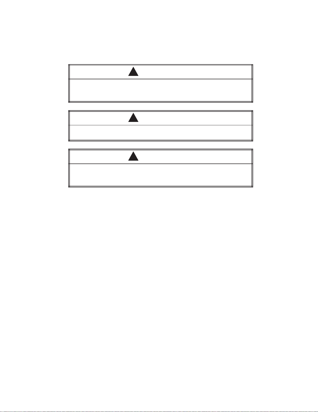
DANGER
!
DANGER
result in death or serious injury
DANGER is limited to the most extreme situations.
W
ARNING indicates a potentially hazardous situation that, if not avoided, could
result in death or serious injury, and/or property damage.
CAUTION indicates a potentially hazardous situation that, if not avoided, could
result in minor or moderate injury, and/or damage to property
CAUTION is also used for property-damage-only accidents.
indicates an imminently hazardous situation that, if not avoided, will
.
WARNING
!
CAUTION
!
.
Copyright
1995 by Siemens Industrial Automation, Inc.
All Rights Reserved — Printed in USA
Reproduction,
Siemens Industrial
reserved.
Since Siemens Industrial Automation, Inc., does not possess full access to data concerning all of the uses and applications of
customer’
of others which may result from our assistance.
transmission, or use of this document or contents is not permitted without express consent of
Automation, Inc. All rights, including rights created by patent grant or registration of a utility model or design, are
s products, we do not assume responsibility either for customer product design or for any infringements of patents or rights
Page 3

MANUAL PUBLICA
TION HISTOR
Y
SIMATIC
Or
Refer to this history in all correspondence and/or discussion about this manual.
Event Date Description
Original Issue
Second Edition
505 Isolated Interrupt Discr
der Manual Number: PPX:505-8123-2
03/93
04/95
ete Input Modules User Manual
Original Issue (2801386–0001)
Second Edition (2801386–0002)
Page 4

LIST
OF EFFECTIVE P
Pages Description Pages Description
AGES
Cover/Copyright Second
History/Ef
iii — vii
1-1 — 1-3
2-1 — 2-14
3-1 — 3-5
A-1 — A-4
Registration
fective Pages
Second Edition
Second Edition
Second Edition
Second Edition
Second Edition
Second Edition
Second Edition
Edition
Page 5

Preface
Chapter 1 Product Overview
Contents
1.1 Description
Module
Compatibility
Power
Operating
Optional T
Physical
Manual
of Basic Featur
Featur
Sour
Featur
Contents
es 1-2.
. . . . . . . . . . . . . . . . . . . . . . . . . . . . . . . . . . . . . . . . . . . . . . . . . . . . . . . . . . . . . . .
with SIMA
ces 1-2.
. . . . . . . . . . . . . . . . . . . . . . . . . . . . . . . . . . . . . . . . . . . . . . . . . . . . . . . . . . . . . . . . .
Modes
ime Constant Filter
. . . . . . . . . . . . . . . . . . . . . . . . . . . . . . . . . . . . . . . . . . . . . . . . . . . . . . . . . . . . . .
es 1-3.
. . . . . . . . . . . . . . . . . . . . . . . . . . . . . . . . . . . . . . . . . . . . . . . . . . . . . . . . . . . . . .
. . . . . . . . . . . . . . . . . . . . . . . . . . . . . . . . . . . . . . . . . . . . . . . . . . . . . . . . . . . . . .
es 1-2.
TIC CPUs
Chapter 2 Installing the Module
2.1 Overview
Flow
Handling
Visual
2.2 Configuring
Selecting
Selecting
Example
2.3 Inserting
Inserting
2.4 Field Wiring 2-8.
Wiring
Avoiding
Sequence
Wiring
Connecting
of Installation
of T
asks 2-2.
. . . . . . . . . . . . . . . . . . . . . . . . . . . . . . . . . . . . . . . . . . . . . . . . . . . . . . . . . . . . . . . . . . .
the Module
Inspection
the Module Operating Mode
Interrupt T
10-ms T
Settings
the Module into the Base
the Module
. . . . . . . . . . . . . . . . . . . . . . . . . . . . . . . . . . . . . . . . . . . . . . . . . . . . . . . . . . . . . . . . . . . .
Guidelines
Noise
of Inputs
the Terminal Block
the Terminal Block
. . . . . . . . . . . . . . . . . . . . . . . . . . . . . . . . . . . . . . . . . . . . . . . . . . . . . . . . . .
. . . . . . . . . . . . . . . . . . . . . . . . . . . . . . . . . . . . . . . . . . . . . . . . . . . . . . . . . . . . . . .
ype 2-4.
ime-Constant Filter
. . . . . . . . . . . . . . . . . . . . . . . . . . . . . . . . . . . . . . . . . . . . . . . . . . . . . . . . . . . . . . .
. . . . . . . . . . . . . . . . . . . . . . . . . . . . . . . . . . . . . . . . . . . . . . . . . . . . . . . . . . .
. . . . . . . . . . . . . . . . . . . . . . . . . . . . . . . . . . . . . . . . . . . . . . . . . . . . . . . . . . . . . .
. . . . . . . . . . . . . . . . . . . . . . . . . . . . . . . . . . . . . . . . . . . . . . . . . . . . . . . . . . . . . . . .
. . . . . . . . . . . . . . . . . . . . . . . . . . . . . . . . . . . . . . . . . . . . . . . . . . . . . . . . . . . .
. . . . . . . . . . . . . . . . . . . . . . . . . . . . . . . . . . . . . . . . . . . . . . . . . . . . . . . .
. . . . . . . . . . . . . . . . . . . . . . . . . . . . . . . . . . . . . . . . . . . . . . . . . . . . . . . .
. . . . . . . . . . . . . . . . . . . . . . . . . . . . . . . . . . . . . . . . . . . . . . . . . . . . . . .
. . . . . . . . . . . . . . . . . . . . . . . . . . . . . . . . . . . . . . . . . . . . . . . . . . .
. . . . . . . . . . . . . . . . . . . . . . . . . . . . . . . . . . . . . . . . . . . . . . . .
. . . . . . . . . . . . . . . . . . . . . . . . . . . . . . . . . . . . . . . . . . . . . . . . . . .
. . . . . . . . . . . . . . . . . . . . . . . . . . . . . . . . . . . . . . .
. . . . . . . . . . . . . . . . . . . . . . . . . . . . . . . . . . . . . . . . . . . .
. . . . . . . . . . . . . . . . . . . . . . . . . . . . . . . . . . . . . . . . . . . . . .
. . . . . . . . . . . . . . . . . . . . . . . . . . . . . . . . . . . . . . . . . . . . . . . . .
1-2.
1-2.
1-2.
1-3.
2-2.
2-3.
2-3.
2-4.
2-5.
2-6.
2-7.
2-7.
2-8.
2-8.
2-9.
2-11.
2-12.
2.5 Configuring
I/O Memory in the CPU
Chapter 3 Operating the Module
3.1 Operational
Using
the Module in Non-Interrupt Mode
Using
the Module in Interrupt Mode
Writing
Basic
Outline of Interrupt Pr
3.2 Module
LED
Array
Troubleshooting 3-5
Description
an Interrupt RLL Pr
Status and T
. . . . . . . . . . . . . . . . . . . . . . . . . . . . . . . . . . . . . . . . . . . . . . . . . . . . . . . . . . . . . . . . . . . . .
. . . . . . . . . . . . . . . . . . . . . . . . . . . . . . . . . . . . . . . . . . . . . . . . . . . . . . . . . . . . . . . . .
. . . . . . . . . . . . . . . . . . . . . . . . . . . . . . . . . . . . . . . . . . . . . . . . . . . . . . . .
ogram 3-3.
ocessing 3-3.
roubleshooting 3-4.
. . . . . . . . . . . . . . . . . . . . . . . . . . . . . . . . . . . . . . . . . . . . .
. . . . . . . . . . . . . . . . . . . . . . . . . . . . . . . . . . . . . . . .
. . . . . . . . . . . . . . . . . . . . . . . . . . . . . . . . . . . . . . . . . . . . .
. . . . . . . . . . . . . . . . . . . . . . . . . . . . . . . . . . . . . . . . . . . . . . . .
. . . . . . . . . . . . . . . . . . . . . . . . . . . . . . . . . . . . . . . . . . . .
. . . . . . . . . . . . . . . . . . . . . . . . . . . . . . . . . . . . . . . . . . . . .
Contents iii
2-14.
3-2.
3-2.
3-2.
3-4.
Page 6

Appendix A Specifications
A.1 Specifications A-2.
A.2 Terminal
Block W
. . . . . . . . . . . . . . . . . . . . . . . . . . . . . . . . . . . . . . . . . . . . . . . . . . . . . . . . . . . . . . . . .
orksheet A-4.
. . . . . . . . . . . . . . . . . . . . . . . . . . . . . . . . . . . . . . . . . . . . . . . . . . . . . .
iv Contents
Page 7

List of Figures
Figur
e 1-1
Figur
e 2-1
Figur
e 2-2
Figur
e 2-3S1 Dipswitch Settings
Figur
e 2-4S2 Dipswitch Settings
Figur
e 2-5
Figur
e 2-6
Figur
e 2-7
Figur
e 2-8
Figur
e 2-9
Figur
e 2-10
Figur
e 2-11
Figur
e 3-1
Figur
e A-1
DC
Interrupt Input Module
Flowchart
Location
Example
Inserting
I/O Terminals 2-9.
Field
Installing
Terminal
Sample
Interrupt
Input Ter
of Interrupt Dipswitch Gr
Interrupt T
the Module into the Base
Input W
the Terminal Block
Blocks
I/O Module Definition Chart
Input Module Faceplate and LED Display
minal W
. . . . . . . . . . . . . . . . . . . . . . . . . . . . . . . . . . . . . . . . . . . . . . . . .
of Installation
. . . . . . . . . . . . . . . . . . . . . . . . . . . . . . . . . . . . . . . . . . . . . . . . . . . . . . . . . . . . . .
iring Examples
. . . . . . . . . . . . . . . . . . . . . . . . . . . . . . . . . . . . . . . . . . . . . . . . . . . . . . . . . . .
orksheet A-4.
. . . . . . . . . . . . . . . . . . . . . . . . . . . . . . . . . . . . . . . . . . . . . . . . . . . .
oup 2-4.
. . . . . . . . . . . . . . . . . . . . . . . . . . . . . . . . . . . . . .
. . . . . . . . . . . . . . . . . . . . . . . . . . . . . . . . . . . . . . . . . . . . . . . . . . . . . . .
. . . . . . . . . . . . . . . . . . . . . . . . . . . . . . . . . . . . . . . . . . . . . . . . . . . . . . .
ype Settings
. . . . . . . . . . . . . . . . . . . . . . . . . . . . . . . . . . . . . . . . . . . . .
. . . . . . . . . . . . . . . . . . . . . . . . . . . . . . . . . . . . . . . . . .
. . . . . . . . . . . . . . . . . . . . . . . . . . . . . . . . . . . . . . . . . . . . . . . . .
. . . . . . . . . . . . . . . . . . . . . . . . . . . . . . . . . . . . . . . . . . . . . . . . .
. . . . . . . . . . . . . . . . . . . . . . . . . . . . . . . . . . . . . . .
. . . . . . . . . . . . . . . . . . . . . . . . . . .
. . . . . . . . . . . . . . . . . . . . . . . . . . . . . . . . . . . . . . . . . . . . . . . . . .
1-3.
2-2.
2-5.
2-5.
2-6.
2-7.
2-10.
2-12.
2-13.
2-14.
3-4.
Contents v
Page 8

List
of T
T
able 3-1
T
able 3-2
T
able A-1
T
able A-2
T
able A-3
ables
Logical
Troubleshooting
Environmental
Physical
Electrical/Performance
Points Corr
Specifications
Specifications
esponding to Interrupt Inputs 9 – 16
Chart
. . . . . . . . . . . . . . . . . . . . . . . . . . . . . . . . . . . . . . . . . . . . . . . . . . . . . .
. . . . . . . . . . . . . . . . . . . . . . . . . . . . . . . . . . . . . . . . . . . . . . .
. . . . . . . . . . . . . . . . . . . . . . . . . . . . . . . . . . . . . . . . . . . . . . . . . . . . .
Specifications
. . . . . . . . . . . . . . . . . . . . . . . . . . . . . . . . . . . . . . .
. . . . . . . . . . . . . . . . . . . . . . . .
3-2.
3-5.
A-2.
A-2.
A-3.
vi Contents
Page 9

Preface
This
manual provides the information needed to install, wire, and configure
the following SIMA
PPX:505–4317
PPX:505–4318
PPX:505–4319
Except for their input voltage differences, these modules function
identically.
TIC
505 Isolated
Interrupt Discrete Input Modules:
24 VDC
48 VDC
125 VDC
Other Manuals
Agency Appr
ovals
Refer to the manuals listed below for instructions on installing,
programming, and troubleshooting your controller and I/O. The x in the
order number refers to the latest edition.
• SIMA
• SIMATIC 525/535
• SIMATIC
• SIMATIC
• SIMATIC 560T/565T System
• SIMATIC
• The user manual for your release of TISOFT
The Interrupt Input Modules meet the standards of the following agencies:
•
•
TIC 505 Programming Reference Manual
Hardware/Installation Manual
(PPX:505–8103–x)
545
System
555
System
545/555
Underwriters Laboratories: UL Listed (Industrial Control Equipment)
Canadian Standards Association: CSA Certified (Process Control
Equipment)
Manual
Manual
System
(PPX:545–8101–x)
(PPX:555–8101–x)
Manual
Manual
(PPX:560/565–8109–x)
(PPX:545/555–8101–x)
(PPX:505–8104–x)
•
Factory Mutual Approved; Class I, Div
• V
erband Deutscher Elektrotechniker (VDE) 0160 Clearance/Creepage
for Electrical Equipment (Self-Compliance)
Series 505 products have been developed with consideration of the draft
standard of the International Electrotechnical Commission Committee
proposed standard (IEC-65A/WG6) for programmable controllers (released
as IEC 1
and T
Inc., for a listing of the standards to which Series 505 complies.
elephoning for
T
Assistance
SIMATIC 505 Interrupt Input Module User Manual
For technical assistance, contact your Siemens Industrial Automation, Inc.
distributor or sales office. If you need assistance in contacting your U.S.
distributor or sales office, call 1–800–964–41
131–2, Programmable Controllers Part 2: Equipment Requirements
ests, First Edition, 1992–09). Contact Siemens Industrial Automation,
. 2 Hazardous Locations
14.
Preface
vii
Page 10

Chapter 1
1.1 Description
Module
Compatibility
Power
Operating
Optional T
Physical
Manual
Featur
Sour
Featur
Contents
Product
of Basic Featur
es 1-2.
. . . . . . . . . . . . . . . . . . . . . . . . . . . . . . . . . . . . . . . . . . . . . . . . . . . . . . . . . . . . . . .
with SIMA
ces 1-2.
. . . . . . . . . . . . . . . . . . . . . . . . . . . . . . . . . . . . . . . . . . . . . . . . . . . . . . . . . . . . . . . . .
Modes
ime Constant Filter
. . . . . . . . . . . . . . . . . . . . . . . . . . . . . . . . . . . . . . . . . . . . . . . . . . . . . . . . . . . . . .
es 1-3.
. . . . . . . . . . . . . . . . . . . . . . . . . . . . . . . . . . . . . . . . . . . . . . . . . . . . . . . . . . . . . .
. . . . . . . . . . . . . . . . . . . . . . . . . . . . . . . . . . . . . . . . . . . . . . . . . . . . . . . . . . . . . .
es 1-2.
. . . . . . . . . . . . . . . . . . . . . . . . . . . . . . . . . . . . . . . . . . . . . . . . . . .
TIC CPUs
. . . . . . . . . . . . . . . . . . . . . . . . . . . . . . . . . . . . . . . . . . . . . . . . . . .
. . . . . . . . . . . . . . . . . . . . . . . . . . . . . . . . . . . . . . . . . . . . . . . .
Overview
1-2.
1-2.
1-2.
1-3.
SIMATIC 505 Interrupt Input Module User Manual
Product Overview
1-1
Page 11

1.1 Description of Basic Features
Module Featur
es
Compatibility with
SIMA
TIC CPUs
Power Sour
ces
Operating Modes
The
SIMA
TIC 505 Isolated Interrupt Input Modules have 16 discrete input
circuits and operate on different voltages depending on the module. The
PPX:505–4317 operates on 24 VDC, the PPX:505–4318 on 48 VDC, and the
PPX:505–4319 on 125 VDC. Up to 8 of the 16 points can be configured as
interrupt points. Isolation is provided between each point. The modules
operate identically except for differences in input voltage.
The Interrupt Input Modules are compatible with all Series 505 bases.
The Interrupt Input Modules are compatible with all SIMA
TIC 505 CPUs
when used in the non-interrupt mode.
When interrupt mode is selected for any of the configurable inputs, the
module is compatible with the SIMA
TIC 545 and 555 CPUs with Firmware
Release 2.1 (or greater). Consult the release notes or other associated
documentation to determine if interrupt mode is supported by a particular
CPU.
The Interrupt Input Modules sense incoming DC signals from field devices
and operate on power supplied by the I/O base backplane. Refer to your
system manual for instructions on supplying power to the system I/O base.
The Interrupt Input Module can be used in one of the following two modes.
Optional T
ime
Constant Filter
•
16 isolated discrete inputs, all
non-interrupt
mode:
When this module is used in non-interrupt mode, it functions as a
standard 16-point discrete input module and can be installed in any
base (local or remote) of a Series 505 programmable controller system.
•
Configurable mix of
interrupt
inputs and non-interrupt inputs:
When this module is used in interrupt mode, it functions as a 32-point
I/O module (16 physical inputs and 16 internal points) and can only be
installed in the
local
base
of the system. Local Base is defined as the
I/O base containing the CPU.
Interrupt input mode triggers an immediate response to a field device
condition without having to wait for the CPU to complete its program scan
cycle.
Y
ou can configure the module to detect transitions from on to off, off to on,
or either edge when you select interrupt type for a pair of input points.
An eight-position dipswitch allows you to enable a 10-ms filter on any of the
16 physical input points in groups of two.
1-2
Product Overview
SIMATIC 505 Interrupt Input Module User Manual
Page 12
Physical Featur
es
The
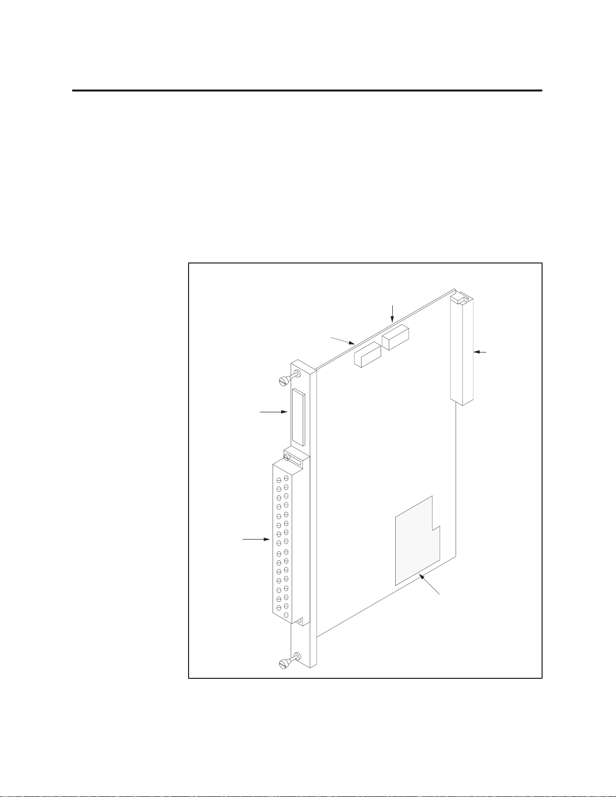
Interrupt Input Modules have two groups of dipswitches located at the
top of the board, as shown in Figure 1-1. The module includes a standard
input terminal connector which can be detached from the module without
having to remove the module from the base. An LED array on the faceplate
shows input status for each point and also interrupt enable mode.
Manual Contents
Chapter 2 describes how to configure the dipswitches, wire the terminal
block, and install the module.
Chapter 3 describes the basic operating features and the use of the LED
array for reading the status of the inputs.
Switch
Interrupt T
Switch S2
10-ms Filter
Dipswitches
Input Status
LED Array
S1
ype
Dipswitches
Backplane
Connector
Input
Terminal
Block
Figure 1-1 DC
SIMATIC 505 Interrupt Input Module User Manual
Chart showing
dipswitch settings
Interrupt Input Module
Product Overview
1-3
Page 13

Chapter 2
2.1 Overview
Flow
Handling
Visual
2.2 Configuring
Selecting
Selecting
Example
2.3 Inserting
Inserting
2.4 Field Wiring 2-8.
Wiring
Avoiding
Sequence
Wiring
Connecting
2.5 Configuring
of Installation
of T
asks 2-2.
the Module
Inspection
Interrupt T
10-ms T
Settings
the Module into the Base
the Module
Guidelines
Noise
of Inputs
the Terminal Block
Installing
. . . . . . . . . . . . . . . . . . . . . . . . . . . . . . . . . . . . . . . . . . . . . . . . . . . . . . . .
. . . . . . . . . . . . . . . . . . . . . . . . . . . . . . . . . . . . . . . . . . . . . . . . . . . . . . . . . . . . . . . . . . .
. . . . . . . . . . . . . . . . . . . . . . . . . . . . . . . . . . . . . . . . . . . . . . . . . . . . . . . . . .
. . . . . . . . . . . . . . . . . . . . . . . . . . . . . . . . . . . . . . . . . . . . . . . . . . . . . . . . . . . . . . .
the Module Operating Mode
ype 2-4.
. . . . . . . . . . . . . . . . . . . . . . . . . . . . . . . . . . . . . . . . . . . . . . . . . . . . . . . .
ime-Constant Filter
. . . . . . . . . . . . . . . . . . . . . . . . . . . . . . . . . . . . . . . . . . . . . . . . . . . . . . . . . . . . . . .
. . . . . . . . . . . . . . . . . . . . . . . . . . . . . . . . . . . . . . . . . . . . . .
. . . . . . . . . . . . . . . . . . . . . . . . . . . . . . . . . . . . . . . . . . . . . . . . . . . . . . . . . . .
. . . . . . . . . . . . . . . . . . . . . . . . . . . . . . . . . . . . . . . . . . . . . . . . . . . . . . . . . . . . . . . . . . . .
. . . . . . . . . . . . . . . . . . . . . . . . . . . . . . . . . . . . . . . . . . . . . . . . . . . . . . . . . . . . . .
. . . . . . . . . . . . . . . . . . . . . . . . . . . . . . . . . . . . . . . . . . . . . . . . . . . . . . . . . . . . . . . .
. . . . . . . . . . . . . . . . . . . . . . . . . . . . . . . . . . . . . . . . . . . . . . . . . . . . . . . . . . . .
. . . . . . . . . . . . . . . . . . . . . . . . . . . . . . . . . . . . . . . . . . . . . . . . . . . . . . .
the Terminal Block
I/O Memory in the CPU
. . . . . . . . . . . . . . . . . . . . . . . . . . . . . . . . . . . . . . . . . . . . . . . . .
. . . . . . . . . . . . . . . . . . . . . . . . . . . . . . . . . . . . . . .
. . . . . . . . . . . . . . . . . . . . . . . . . . . . . . . . . . . . . . . . . . . .
. . . . . . . . . . . . . . . . . . . . . . . . . . . . . . . . . . . . . . . . . . . . .
the Module
2-2.
2-3.
2-3.
2-4.
2-5.
2-6.
2-7.
2-7.
2-8.
2-8.
2-9.
2-11.
2-12.
2-14.
SIMATIC 505 Interrupt Input Module User Manual
Installing the Module
2-1
Page 14
2.1 Overview of Installation
Flow of T
asks
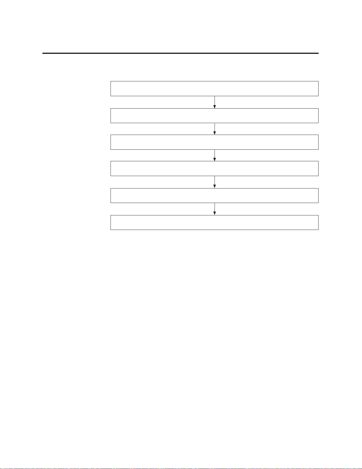
Figure 2-1
shows the organization of the tasks described in this chapter
Configure
Wire and connect input terminal block
Set I/O configuration with
W
rite I/O configuration to controller memory
operating mode dipswitches
Insert module into base
Power up
TISOFT
programming device
.
Figure 2-1 Flowchart
of Installation
2-2
Installing the Module
SIMATIC 505 Interrupt Input Module User Manual
Page 15

Handling the Module
Many
integrated circuit (IC) devices are susceptible to damage by the
discharge of static electricity
. Follow the suggestions listed below to reduce
the probability of damage to these devices when you are handling a CPU, a
base controller
, or any of the I/O modules.
Both the module and the person handling the module should be at the same
ground potential. T
• T
ransport the module in an anti-static container or antistatic material.
•
Ensure that the work area has a conductive pad with a lead connecting
o accomplish this, fulfill the following conditions.
it to a common ground.
•
Ground yourself by making contact with the conductive pad and/or by
wearing a grounded wrist strap.
isual Inspection
V
If there is any visible damage to the module, contact your Siemens
Industrial Automation, Inc. distributor or sales office for replacement.
SIMATIC 505 Interrupt Input Module User Manual
Installing the Module
2-3
Page 16
2.2 Configuring the Module Operating Mode
Selecting Interrupt Type
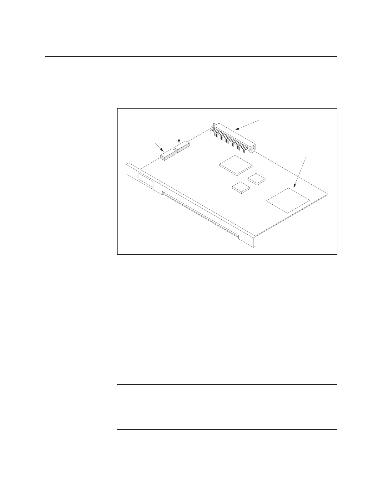
Two
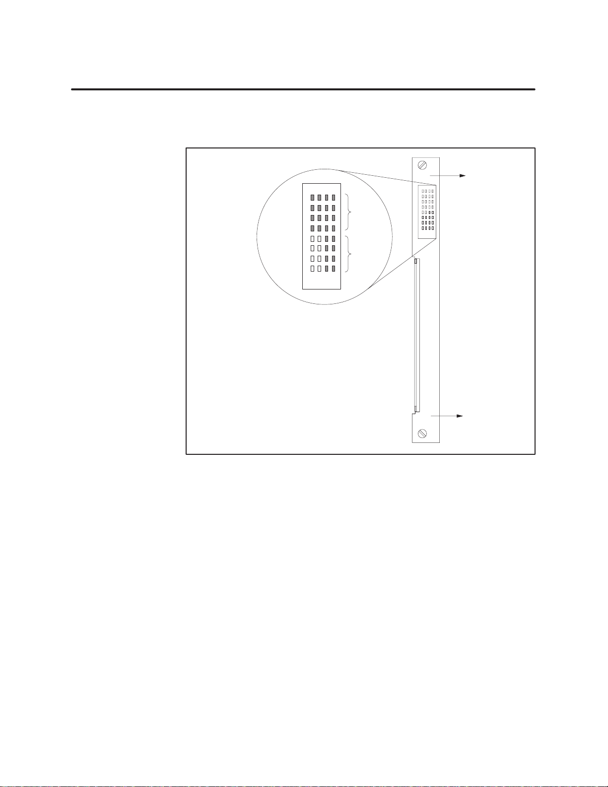
groups of dipswitches are located on the top edge of the module facing
upward, as shown in Figure 2-2. The set of switches closest to the backplane
connector
, labeled S1, is the group used to select interrupt type for points 9
through 16.
Switch S2
10-ms Filter
Dipswitches
Switch S1
Interrupt T
Dipswitches
ype
Backplane
Connector
Chart
showing
dipswitch settings
Figure 2-2 Location
of Interrupt Dipswitch Gr
oup
The interrupt type is selected for pairs of input points and cannot be
selected individually
interrupt mode for a pair of input points, as listed below
. Each pair of dipswitches in the S1 group selects the
.
Switches 1 and 2 control points 9 and 10
Switches 3 and 4 control points 1
1 and 12
Switches 5 and 6 control points 13 and 14
Switches 7 and 8 control points 15 and 16
Y
ou configure each pair of points to detect on-to-off, off-to-on, or either
transitions according to the way you set each pair of dipswitches.
NOTE:
types for the configurable input points. T
This section discusses how to set the dipswitches to select interrupt
o operate as interrupt inputs, these
points must also be enabled individually in the user program using the
internal logic outputs assigned to this task. Refer to Chapter 3 for more
information.
-edge
2-4
Installing the Module
SIMATIC 505 Interrupt Input Module User Manual
Page 17
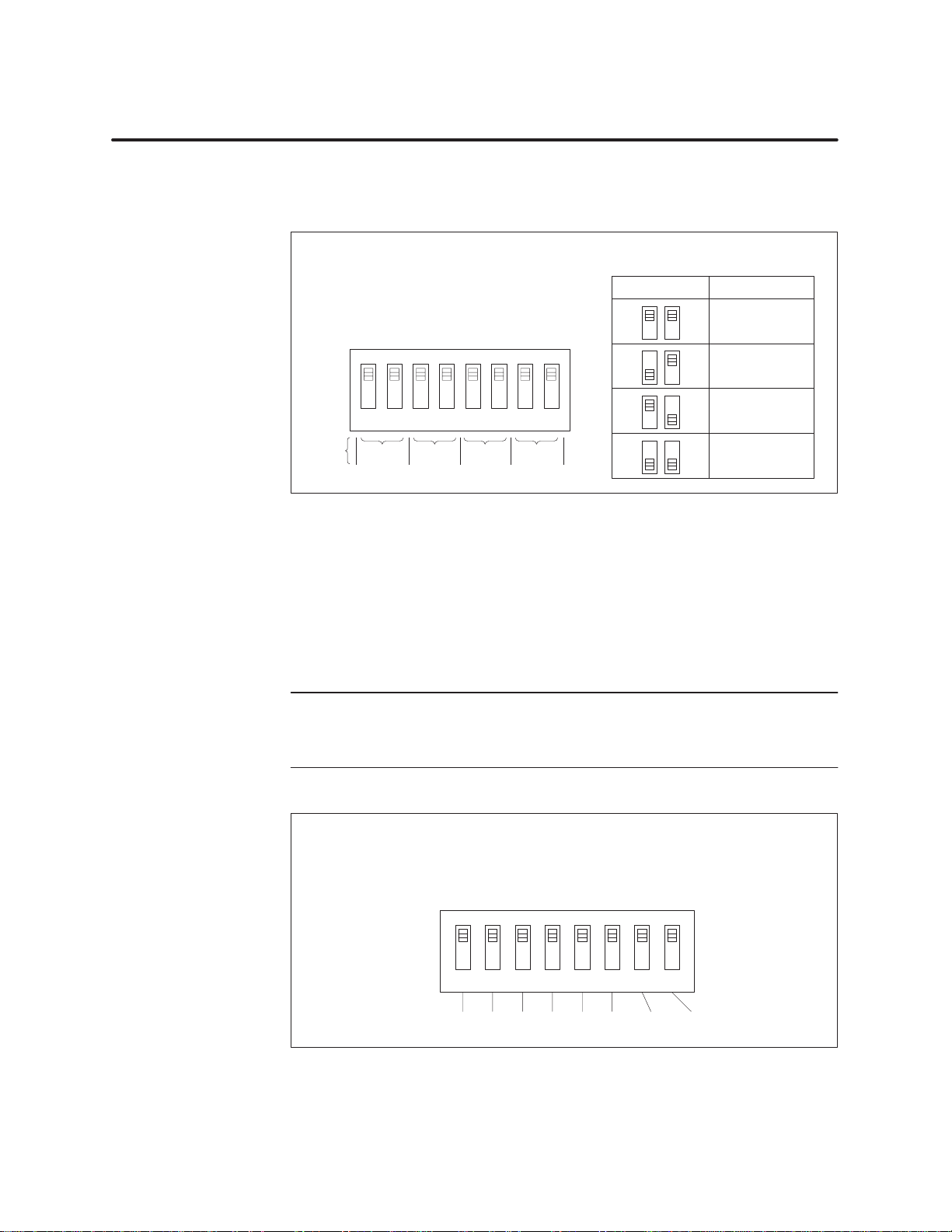
Figure 2-3
shows how to set the dipswitches in S1 to select the interrupt
type for each pair of input points.
Selecting 10-ms Time-Constant Filter
Switch
S1
Interrupt T
Each pair of switches selects interrupt type
for a pair of input points, as shown here.
A B ABABAB
OFF
y
ype Switches
b
ON
12345678
Input
Points
9/10 11/12 13/14 15/16
Figure 2-3 S1
Dipswitch Settings
Select Interrupt Type for each pair of
points according to the chart below
AB
Off Off
Off
On
Off
On
On On
Interrupt T
No Interrupt
On-to-of
Of
f-to-on edge
Either edge
ype
f edge
.
The second set of dipswitches, located closest to the faceplate of the module
and labeled S2, is used to select input filter time constants of 10 ms per pair
of points, as shown in Figure 2-4. You can filter any of the 16 input points,
both non-interrupting and interrupting. The 10-ms filter may be useful in
applications where relay chatter or switch bounce is a potential problem.
NOTE:
Filtering delays module response time to input transitions. For
interrupt applications with critical response time requirements, be careful
to take into account the time delay before you decide to use these filters.
OFF
y
b
ON
Input Points:
SIMATIC 505 Interrupt Input Module User Manual
Switch
S2
10-ms Filter Switches
Each switch activates the filter for a
pair of input points, as shown here.
12345678
9/10 11/12 13/14 15/161/2 3/4 5/6 7/8
Figure 2-4 S2
Dipswitch Settings
Installing the Module
Of
f = no filter
On = 10-ms filter
2-5
Page 18
Configuring the Module Operating Mode (continued)
Example Settings
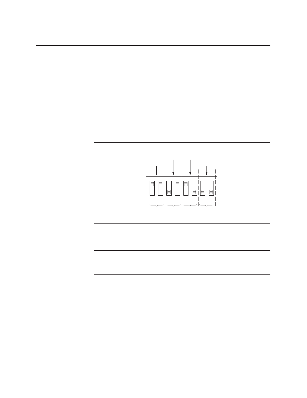
Figure 2-5
shows an example of a configuration that enables interrupt mode
and the dipswitch setting used for the given configuration.
•
Points 9 and 10 are configured to be non-interrupting.
•
Points 1
on-to-off
•
Points 13 and 14 are configured to generate an interrupt upon an
off-to-on
•
Points 15 and 16 are configured to generate an interrupt upon
1 and 12 are configured to generate an interrupt upon an
transition.
transition.
transition.
Switch S1
On-to-Of
No
Interrupt
A B ABABAB
OFF
y
b
ON
12345678
f edgeOff-to-On edge
Either edge
either
Input Points:
Figure 2-5 Example
9/10 11/12 13/14 15/16
Interrupt T
ype Settings
NOTE: To operate as interrupt inputs, these points must also be enabled
individually in the user program using the internal logic outputs assigned to
this task. Refer to Chapter 3 for more information.
2-6
Installing the Module
SIMATIC 505 Interrupt Input Module User Manual
Page 19
2.3 Inserting the Module into the Base
Failure
to follow appropriate safety precautions could result in death or serious
injury and/or damage to equipment.
T
o minimize risk of potential shock hazard, turn off power to the I/O base and to
any modules installed in the base before inserting or removing a module or
installing a terminal block.
The power must be turned off to the I/O base and to any modules installed in
the base before inserting or removing a module or installing a terminal block.
The
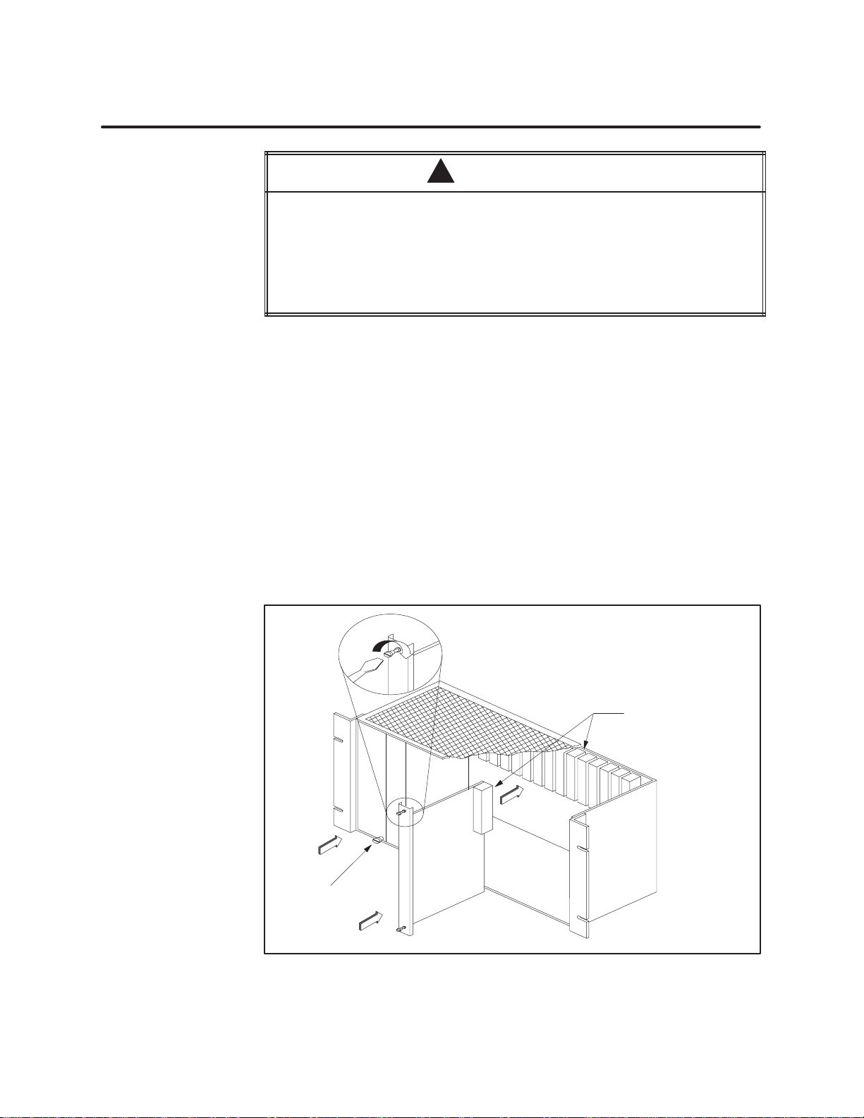
Inserting the Module
Interrupt Input Modules are single-wide and may be installed in any
available slot for single-wide modules. Do not touch the printed circuit
board (PCB) while inserting the module. This could cause electrostatic
damage to its components. To insert the module, follow these steps.
1.
Position the module so that the front bezel is facing you.
2.
Hold the top and bottom of the bezel and slide the module carefully into
the slot, pushing it all the way into the base. If you have inserted the
module correctly
, you will feel a slight increase in resistance as the
module mates with the backplane connector
WARNING
!
. (See Figure 2-6).
3.
Use a flat-head screwdriver to tighten the screws at the top and bottom
of the bezel. This grounds the module to the base. Do not overtighten.
0.3
N–m (2.61 in.-lbs.) minimum torque
0.6 N–m (5.22 in.-lbs.) maximum torque
Backplane
connectors
C
P
U
P
S
Earth
Ground
Figure 2-6 Inserting
SIMATIC 505 Interrupt Input Module User Manual
the Module into the Base
Installing the Module
2-7
Page 20
2.4 Field Wiring
W
iring Guidelines
A
voiding Noise
These
modules do not require user-supplied power. A module consumes a
maximum of 2.0 W of +5 V power from the base backplane.
The modules have been designed to work with up to 1000 feet (303 meters)
of wire to the switch. The size of the wire used must be adequate for switch
current. T
o prevent noise on the signal wiring, keep signal and power wiring
separate. For input or output signals and class 2 power supply wires, use
shielded, twisted-pair cable (12–26 A
WG or 0.16–3.2 mm2, either stranded
or solid-type).
WARNING
!
Use
supply wires suitable for at least 75°C. Signal wiring connected to this
module must be rated at least 300 V
W
iring that does not meet the requirements could cause death and/or serious
injury or damage to equipment.
Ensure that your wire is suitable for at least 75
nected to this module is rated at least 300 V
To
minimize unwanted noise, follow these wiring installation guidelines.
.
°
C, and that signal wiring con
.
-
•
Use the shortest possible wires.
•
Separate discrete and analog wires.
• A
void placing signal wires parallel to high-energy wires. If the two
must meet, cross them at right angles.
• A
void bending the wire into sharp angles.
•
Use wireways for wire routing.
•
When using shielded wires, ground them only at the source end for
better noise immunity
•
Place wires so that they do not interfere with existing wiring.
•
Label the wires.
NOTE:
Terminate shielding
the user power supply
same earth ground as the transmitter
.
for the output cable at the same earth ground as
. T
erminate shielding for the input signal wire at the
.
2-8
Installing the Module
SIMATIC 505 Interrupt Input Module User Manual
Page 21
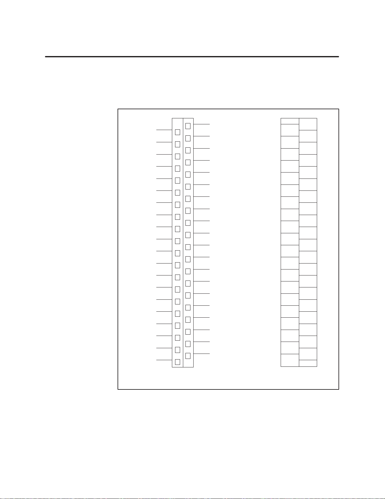
Sequence of Inputs
Figure 2-7
shows the sequence of inputs for the modules as well as the input
terminal label provided with the module. The right column represents the
right row of screws on the terminal block and the left column represents the
left row
.
Not used
Input 1–
Input 2–
Input 3–
Input 4–
Not used
Input 5–
Input 6–
Input 7–
Input 8–
Not used
Input 9–
Input 10–
1–
Input 1
Input 12–
Not used
Input 13–
Input 14–
Input 15–
Input 16–
AR
A1
A2
A3
A4
BR
B1
B2
B3
B4
CR
C1
C2
C3
C4
DR
D1
D2
D3
D4
AC
A5
A6
A7
A8
BC
B5
B6
B7
B8
CC
C5
C6
C7
C8
DC
D5
D6
D7
D8
Not used
Input 1+
Input 2+
Input 3+
Input 4+
Not used
Input 5+
Input 6+
Input 7+
Input 8+
Not used
Input 9+
Input 10+
Input 1
1+
Input 12+
Not used
Input 13+
Input 14+
Input 15+
Input 16+
AC
AR
A5
A1
A6
A2
A7
A3
A8
A4
BC
BR
B5
B1
B6
B2
B7
B3
B8
B4
CC
CR
C5
C1
C6
C2
C7
C3
C8
C4
DC
DR
D5
D1
D6
D2
D7
D3
D8
D4
T
erminal designators
(both
connector models)
SIMATIC 505 Interrupt Input Module User Manual
Figure 2-7 I/O Terminals
Installing the Module
T
erminal label
2-9
Page 22
Field Wiring (continued)
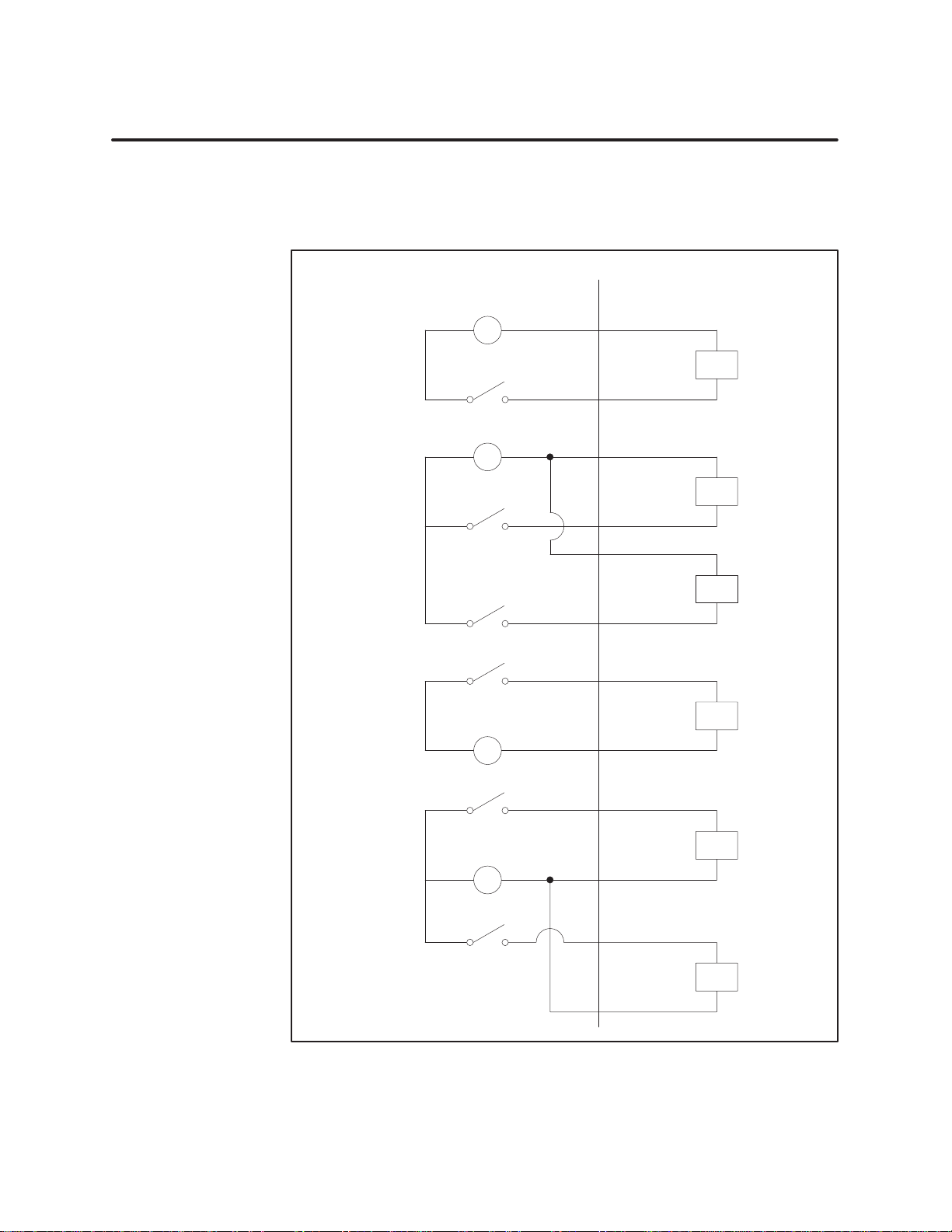
The
operate when wired in either a sinking or sourcing configuration, as shown
in Figure 2-8.
Interrupt Input Modules inputs are floating. Therefore, the inputs will
Sourcing
Configuration
(Isolated)
Sourcing
Configuration
Sinking
Configuration
(Isolated)
Field Side
+–
+–
+–
Module Side
Input
–
Input +
Input –
Input +
Input –
Input +
Input –
Input +
2-10
Installing the Module
Sinking
Configuration
+–
Figure 2-8 Field
SIMATIC 505 Interrupt Input Module User Manual
Input W
Input –
Input +
Input –
Input +
iring Examples
Page 23

W
iring the T
Block
erminal
You
can use either of the terminal blocks shown in Figure 2-10. Both
terminal blocks are removable. T
procedure below
1. T
urn the terminal block, with the screw-heads facing you, until the
.
o wire the terminal block, follow the
A-series of terminals is at the top and the D series is at the bottom.
2.
Using Figure 2-7 as a wiring guide, start with the D’s and loosen the
appropriate terminal block screws.
3.
Strip back the insulation on the wires about 1/4 to 3/8 inch or one
centimeter
. Use a 12–26 A
WG or a 0.16–3.2 mm2 metric gauge wire of
either stranded or solid type.
(If you are using the side-accessible connector number 2587705–8010, a
spade or a ring lug may be attached to the end of the wire.)
4.
Connect the end of the wire to the loosened terminal block screw and
tighten the screw firmly
. Once the D’
s are completed, connect the C’
s,
and continue until the terminal block is completely wired.
NOTE: An easy-to-use, stick-on label is provided separately with space
available to write in the name of each input. W
rite in the corresponding
input names and apply the label to the flat side of the terminal block.
Appendix A contains a worksheet to help you document the input labeling.
SIMATIC 505 Interrupt Input Module User Manual
Installing the Module
2-11
Page 24
Field Wiring (continued)
Connecting the
Ter
minal Block
To
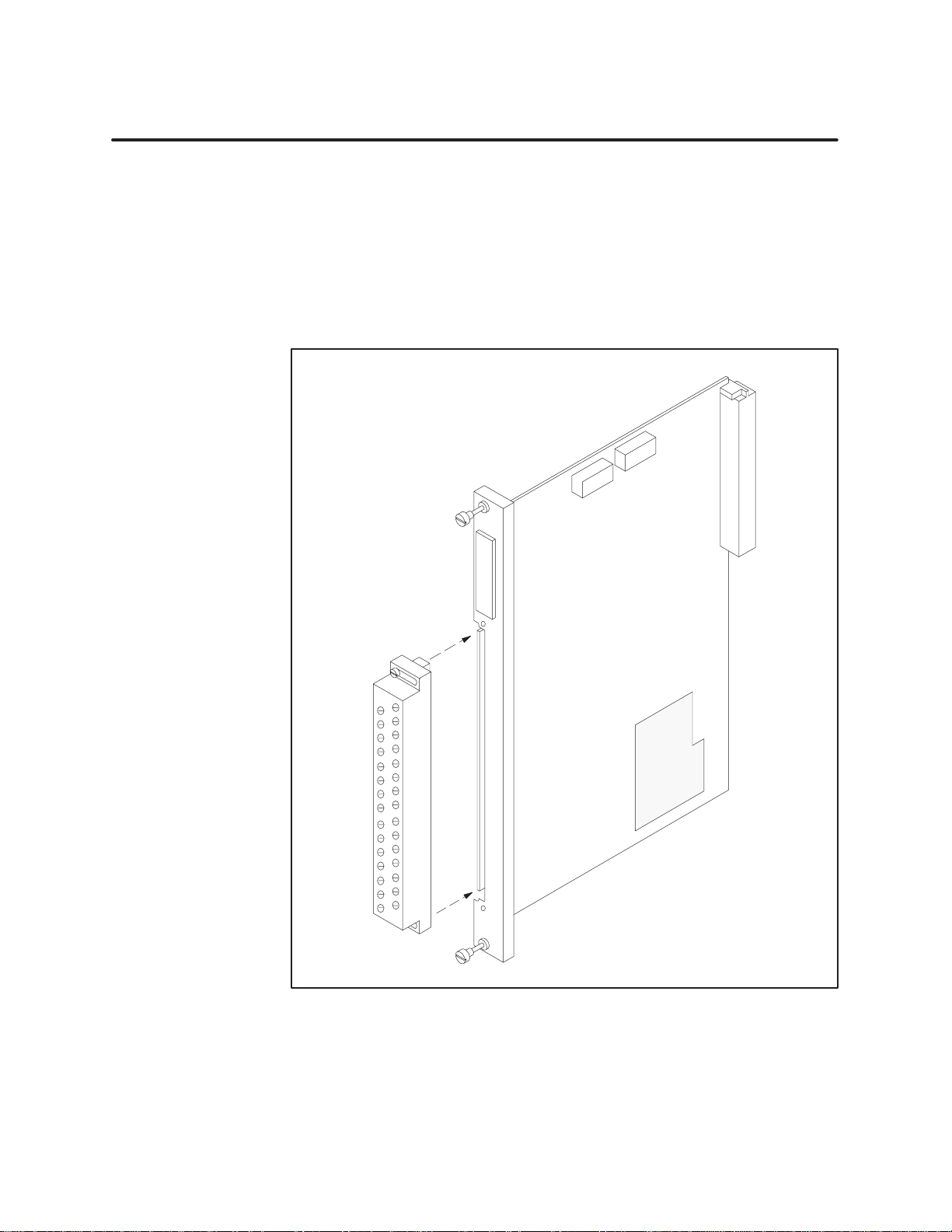
connect the terminal block to
the module, follow these steps. (See
Figure 2-9.)
1.
Align the terminal block with the edge card connector on the bezel.
2.
Press firmly at both ends of the terminal block until it is seated.
3. T
ighten the screws at the top and bottom. Do not over
-tighten.
2-12
Installing the Module
Figure 2-9
Installing the Terminal Block
SIMATIC 505 Interrupt Input Module User Manual
Page 25
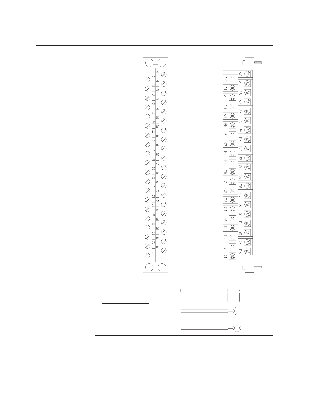
P/N
2587705–801
Front-accessible
1
P/N 2587705–8010
Side-accessible
Connector –801
1 accepts only
the wire termination shown below
Wire
Gauge: 12–26
SIMATIC 505 Interrupt Input Module User Manual
Connector
–8010 accepts any of the
three wire terminations shown below
Wire
Gauge: 12–26
Stud Size: #4 (2.5mm)
Amp Part#: 321462
Stud Size: #4 (2.5mm)
Amp Part#: 327891
1cm
(0.39
.
in.)
Figure 2-10 Terminal
1cm
in.)
(0.39
Blocks
Installing the Module
.
Max. Width:
5.54 mm
(0.218 in.)
Max. Width:
4.62 mm
(0.182 in.)
2-13
Page 26
2.5 Configuring I/O Memory in the CPU
After
the module has been inserted into the I/O base, you must register the
I/O addresses for each module in the CPU memory
automatically register addresses in the CPU when it is inserted.) This is
important because even though the module may appear to be operating
correctly
configured in the I/O map. A programming device must be connected to the
CPU to configure the I/O map and verify CPU- to-module communications.
Apply power to the base and follow these steps to configure the I/O memory
map.
1.
2.
3.
, it will not communicate with the CPU unless the module is
Access the Configure I/O function menu.
Select the appropriate channel and base number
Execute the Read Base function.
If the module is configured for non-interrupt mode, the module appears
as 16 X inputs, as shown in Figure 2-1
If the module is configured for interrupt mode, the module appears as
24 X inputs and 8 Y outputs, as shown in Figure 2-1
. (The module does not
.
1, slot 1.
1, slot 2.
4. Y
ou need to assign the starting I/O address and write the completed I/O
configuration to the controller memory
. (In the example for slot 2, the
starting address is set for 0017.)
For more information on configuring the I/O, refer to your TISOFT manual.
I/O Address
Non-interrupt mode:
Interrupt mode:
I/O
MODULE DEFINITION FOR : CHANNEL 1
Slot Address X Y WX WY Function
1
.....
2
.....
3
.....
4
.....
Slot Number
Install
available I/O slot in the I/O base.
the module logs in as 16 inputs (Xs).
the module logs in as 24 Xs and 8 outputs (Ys).
I/O
0001
0017
0000
0000
the module into any
Number of Bit and W
.....
16
..
00
.....
24
..
08
.....
00
..
00
.....
00
..
00
ord I/O
..
..
..
..
BASE 00
..
00 00
00
..
00
..
00
..
SF Module
The Interrupt Input module is
not a Special Function Module.
Base Number
Displays number
of the current base.
00
00
00
.......
.......
.......
.......
Special
No
No
No
No
2-14
Installing the Module
Figure 2-11 Sample
SIMATIC 505 Interrupt Input Module User Manual
I/O Module Definition Chart
Page 27

Chapter 3
3.1 Operational
Using
the Module in Non-Interrupt Mode
Using
the Module in Interrupt Mode
Writing
Basic
3.2 Module
LED
Troubleshooting 3-5
an Interrupt RLL Pr
Outline of Interrupt Pr
Status and T
Array
Operating
Description
. . . . . . . . . . . . . . . . . . . . . . . . . . . . . . . . . . . . . . . . . . . . . . . . . . . . . . . . . . . . . . . . . . . . . .
. . . . . . . . . . . . . . . . . . . . . . . . . . . . . . . . . . . . . . . . . . . . . . . . . . . . . . . . . . . . . . . . .
. . . . . . . . . . . . . . . . . . . . . . . . . . . . . . . . . . . . . . . . . . . . . . . . . . . . . . . .
. . . . . . . . . . . . . . . . . . . . . . . . . . . . . . . . . . . . . . . .
. . . . . . . . . . . . . . . . . . . . . . . . . . . . . . . . . . . . . . . . . . . . .
ogram 3-3.
ocessing 3-3.
roubleshooting 3-4.
. . . . . . . . . . . . . . . . . . . . . . . . . . . . . . . . . . . . . . . . . . . . . . . .
. . . . . . . . . . . . . . . . . . . . . . . . . . . . . . . . . . . . . . . . . . . .
. . . . . . . . . . . . . . . . . . . . . . . . . . . . . . . . . . . . . . . . . . . . .
the Module
3-2.
3-2.
3-2.
3-4.
SIMATIC 505 Interrupt Input Module User Manual
Operating the Module
3-1
Page 28

3.1 Operational Description
Using
the Module
in Non-Interrupt
Mode
If
you decide to use the Interrupt Input Modules in an application that does
not require interrupt inputs, and you have selected the
switch
settings for each of the interrupt point pairs, then the module enters
Non-interrupt Mode when power is applied to the base.
In this mode, the module can be installed in any base (local or remote) of the
system and is recognized by the CPU as having 16 discrete input (X) points,
all of which are available for field connection.
No Interrupt
Using the Module in Interrupt Mode
If you selected an interrupt type for at least one of the pairs of configurable
input points, then the module enters Interrupt Mode when power is applied.
In this mode, the module can only be installed in the local base (the I/O base
containing the CPU module) and is recognized by the CPU as having 24
discrete input (X) points and 8 discrete output (Y) points.
In Interrupt Mode, the points are defined as follows.
•
Points 1 – 8: Non-interrupting field inputs
•
Points 9 – 16: Configurable (interrupting or non-interrupting) field
inputs based upon the settings of the interrupt switches on the module
•
Points 17 – 24: Logical (internal) status inputs that, when set by the
module, report to the CPU which point has generated an interrupt as a
result of a field input transition. Each of these points corresponds to
one of the interrupting field inputs, as shown in T
•
Points 25 – 32: Logical outputs that act as individual interrupt enables
for each of the interrupting field inputs. T
urning on a given output
able 3-1.
point enables interrupting operation on the corresponding input, as
shown in T
T
able 3-1
able 3-1.
Logical Points Corr
esponding to Interrupt Inputs 9 – 16
3-2
Operating the Module
Physical Input
Points (X)
9 17 25
10 18 26
11 19 27
12 20 28
13 21 29
14 22 30
15 23 31
16 24 32
Logical Interrupt Status
Inputs (X)
SIMATIC 505 Interrupt Input Module User Manual
Logical Interrupt Enable
Outputs (Y)
Page 29

W
riting an Interrupt
RLL Pr
ogram
In
order to take advantage of the Interrupt feature of this module, you must
write a Relay Ladder Logic (RLL) program that contains the appropriate
logic to execute the required response to interrupts generated by this
module. For a more detailed description of the requirements and operation
of the interrupt RLL program, refer to the
Manual
Reference Manual
(PPX:545/555–8101–2) and the
(PPX:505–8104–5).
SIMA
TIC TI545/TI555 System
SIMA
TIC TI505 Programming
Basic Outline of Interrupt Processing
The Interrupt Input Module and the CPU work together to process
interrupt signals in the following manner
1.
When a field signal connected to an interrupt input transitions in a
.
manner that matches the interrupt type selected for that input, the
module sets the corresponding interrupt status input point and
generates an interrupt to the CPU.
2.
The CPU detects this interrupt, and, if proper qualifying conditions are
met, executes the interrupt RLL program, provided the CPU is in Run
Mode.
3.
The CPU automatically issues a rearm signal to the module to clear the
current interrupt event and to allow new events.
4.
If an interrupt transition occurs at a given input point while the CPU is
currently processing an interrupt event, the module holds the new
event until the CPU issues the rearm signal to complete processing of
the current event. The module then generates another interrupt to
signal the CPU that a new event has occurred.
NOTE:
is
If an interrupt transition occurs at an input point while the module
holding
an event from the
same
input point, the new event will effectively
be lost, since the module will only generate a single interrupt to the CPU.
This behavior is significant only in pulse-counting applications, where
pulses could potentially be missed if the pulse frequency is too high. Refer to
your CPU’s Release Notes
for specifications on execution times.
SIMATIC 505 Interrupt Input Module User Manual
Operating the Module
3-3
Page 30
3.2 Module Status and Troubleshooting
LED Array
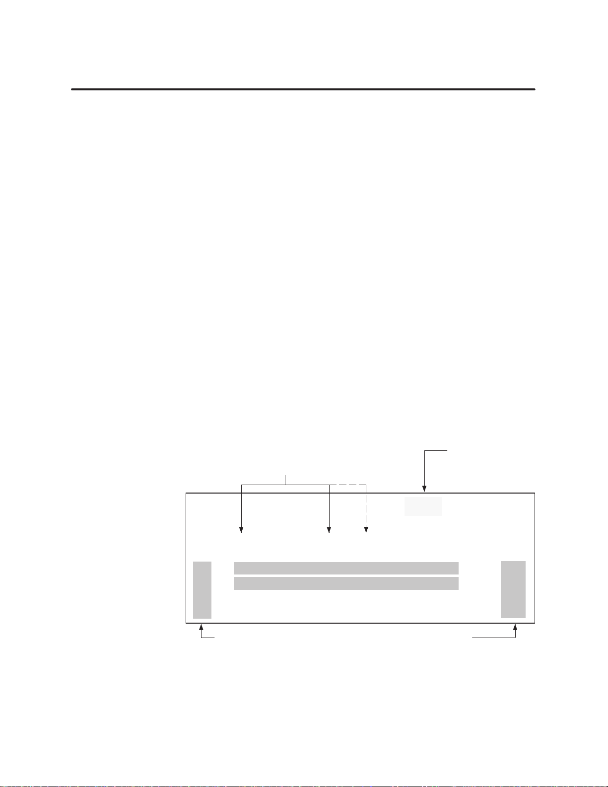
An
LED array showing input and interrupt enable status is located on the
front of the module. (See Figure 3-1.)
24/48/125 VDC
Isolated/Interrupt
PPX:505–4317/
PPX:505–4318/
PPX:505–4319
LED
Elements on Interrupt Input Module
Display Function
A1 – A4
B1
– B4
C1
– C4
D1
– D4
A5
– A8
B5
– B8
C5
– C8
D5
– D8
status of points 1–4
.
. .
status of points 5–8
.
. .
status of points 9–12
.
. .
status of points 13–16
.
. .
not used
.
. .
not used
.
. .
interrupt enable status of points 9–12
.
. .
interrupt enable status of points 13–16
.
. .
Input
Status
pts.
1–16
Interrupt
Enable
Status
3-4
The input status LEDs indicate the state of the input from the logic (PLC)
side, not from the field side. When an input is on, a corresponding LED
turns on.
The interrupt enable LEDs indicate the status of the interrupt enable
logical outputs (points 25 – 32), which enable or disable the interrupt
operation for input points 9 – 16. Interrupt enable status of points 9 to 16 is
indicated by the status of LEDs C5 to C8 and D5 to D8.
These LEDs can be used to check normal module operation as well as to
troubleshoot when unexpected results are experienced.
Operating the Module
Figure 3-1 Interrupt
Input Module Faceplate and LED Display
SIMATIC 505 Interrupt Input Module User Manual
Page 31

LED is not lit
LED is not lit
Troubleshooting
The
LED Input Status Indicators and the CPU indicate whether the module
is operating correctly
corrective actions to take if the module is not operating correctly
Symptom Probable Cause Corrective Action
Incorrect values
Nonfatal error as a
result of the module
. T
able 3-2 shows symptoms, probable causes and
.
able 3-2Troubleshooting Chart
T
Not receiving power Check power supply and
connections.
User program problem Check user program or I/O
configuration.
Wrong terminal block
connections
Faulty LED Return module for repair.
Wrong terminal block
connections
Noise on signal wire
exceeding immunity level
Incorrect or missing
configuration
Module configured
incorrectly
Trace wiring connections.
Trace wiring connections.
Use shielded wire near power
wire; check ground wire to base.
Correctly configure I/O.
Reconfigure the module.
If
you cannot correct the problem, contact your Siemens Industrial
Automation, Inc. distributor or sales office.
SIMATIC 505 Interrupt Input Module User Manual
Operating the Module
3-5
Page 32

Appendix A
Specifications
A.1 Specifications A-2.
A.2 Terminal
Block W
. . . . . . . . . . . . . . . . . . . . . . . . . . . . . . . . . . . . . . . . . . . . . . . . . . . . . . . . . . . . . . . . .
orksheet A-4.
. . . . . . . . . . . . . . . . . . . . . . . . . . . . . . . . . . . . . . . . . . . . . . . . . . . . . .
SIMATIC 505 Interrupt Input Module User Manual
Specifications
A-1
Page 33

A.1 Specifications
T
able A-1
Environmental
Specifications
Operating temperature
Storage temperature
Relative humidity 5% to 95% noncondensing
Pollution degree
Vibration Sinusoidal
Electrostatic discharge IEC 801, Part 2, Level 4, (15 kV)
Shock
Noise immunity, conducted IEC 801, Part 4, Level 3
Noise immunity on user power lines
Noise immunity, radiated IEC 801, Part 3, Level
Isolation 1500 Vrms, input-to-controller
Corrosion protection All parts of corrosion-resistant material or plated or
0 to 60°C (32 to 140
–40 to +70°C (–40 to 158
2, IEC 664, 664A
IEC 68-2-6, Test Fc
0.15 mm peak-to-peak, 10–57 Hz;
1.0 g, 57–150 Hz
Random
IEC 68-2-34, T
equivalent to NAVMA
0.04 g2/Hz, 80–350 Hz, 3dB/Octave rolloff
IEC 68-2-27; T
MIL STD 461B CS01, CS02, and CS06 per part 4,
IEC 255-4, Appendix E; IEEE 472, 2.5 kV
1500 V
rms, point-to-point
painted as corrosion protection
°F)
°F)
est Fdc,
T P–9492
80 – 20 Hz, 350 – 2000 Hz
est Ea
; EEC 4517
3, MIL STD 461B RS01, &RS02
T
able A-2
Module type Series 505 single-wide module
Weight and dimensions of packed module
Weight and dimensions of unpacked module
Input signal wiring Shielded, twisted-pair cable (12–26 A
Spade lug for use with connector 2587705–8010
Ring lug for use with connector 2587705–8010
Minimum torque for bezel screws
Maximum torque for bezel screws
A-2
Specifications
Physical
2 pounds, 15 ounces; 12.75″× 13.5
1 pound, 8 ounces; 10.5″ × 8″ ×
mm2, either stranded or solid-type)
Amp part number 321462
Amp part number 327891
2.61 in-lb (0.3 N-m)
5.22 in-lb (0.6 N-m)
Specifications
0.8
SIMATIC 505 Interrupt Input Module User Manual
″× 3.75″
WG or 0.16–3.2
Page 34

T
able A-3
Module PPX:505–4317 PPX:505–4318 PPX:505–4319
Rated Voltage DC 24 48 125
Input voltage range for ON
VDC UH minimum
VDC UH maximum
Input voltage range for OFF
VDC UL minimum
VDC UL maximum
Input current limits during ON
mA IH minimum
mA IH maximum
Input current for OFF
mA maximum
Number of inputs 16 points in non-interrupt mode (16 Xs) 32 points
Delay time through module 0.5 ms maximum, filter off
Module power from base
Electrical/Performance
10.0
30.0
–30.0
3.0
2.0
10.0
0.5 0.5 0.5
in interrupt mode (24 Xs, 8 Ys):
• 16 physical input points (16 Xs)
• 8 internal logic input points (8 Xs)
• 8 internal logic output points (8 Ys)
10 ms maximum, filter on
2.0 W maximum (1.6 W typical) at +5 V
Specifications
43.0
53.0
–30.0
10.0
1.0
6.0
112.5
137.5
–30.0
25.0
1.0
4.0
SIMATIC 505 Interrupt Input Module User Manual
Specifications
A-3
Page 35

A.2 Terminal Block Worksheet
Not used
Input 1–
Input 2–
Input 3–
Input 4–
Not used
Input 5–
Input 6–
Input 7–
Input 8–
Not used
Input 9–
Input 10–
Input 1
1–
Input 12–
Not used
Input 13–
Input 14–
Input 15–
Input 16–
AR
A1
A2
A3
A4
BR
B1
B2
B3
B4
CR
C1
C2
C3
C4
DR
D1
D2
D3
D4
AC
A5
A6
A7
A8
BC
B5
B6
B7
B8
CC
C5
C6
C7
C8
DC
D5
D6
D7
D8
Not used
Input 1+
Input 2+
Input 3+
Input 4+
Not used
Input 5+
Input 6+
Input 7+
Input 8+
Not used
Input 9+
Input 10+
Input 1
1+
Input 12+
Not used
Input 13+
Input 14+
Input 15+
Input 16+
A-4
Specifications
Figur
e A-1
T
erminal label
Input Ter
minal W
orksheet
SIMATIC 505 Interrupt Input Module User Manual
Page 36

Customer
We would like to know what you think about our user manuals so that we can serve you better.
How would you rate the quality of our manuals?
Accuracy
Organization
Clarity
Completeness
Graphics
Examples
Overall
Size
Index
design
Response
Excellent Good Fair Poor
Would you be interested in giving us more detailed comments about our manuals?
Yes! Please send me a questionnaire.
No. Thanks anyway.
Your Name:
Title:
Telephone Number: ( )
Company Name:
Company Address:
Manual
Manual Assembly Number:
Order Number:
Name:
SIMA
TIC 505 Isolated Interrupt Discrete Input Module
PPX:505–8123–2
Edition: Second
2586546–0085 Date: 04/95
Page 37
FOLD
BUSINESS REPL
FIRST CLASS
POST
AGE WILL BE P
Y MAIL
PERMIT NO.3
AID BY ADDRESSEE
JOHNSON CITY
, TN
ATTN: Technical Communications M/S 519
SIEMENS INDUSTRIAL AUTOMATION INC.
3000 BILL GARLAND RD
P O BOX 1255
JOHNSON CITY TN 37605–1255
FOLD
NO POST
NECESSARY
IF MAILED
IN THE
UNITED ST
AGE
ATES
Page 38

SIMATIC is a registered trademark of Siemens AG.
Series 505 and TISOFT are trademarks of Siemens Industrial Automation, Inc.
Underwriters Laboratories is a registered trademark of Underwriters Laboratories.
 Loading...