

Siemens SIMATIC 500,SIMATIC 505 User Manual

)
%$"'
"' %%! ('!$
#"&#"
DANGER
!
DANGER indicates an imminently hazardous situation that, if not avoided, will
result in death or serious injury .
DANGER is limited to the most extreme situations.
WARNING
!
WARNING indicates a potentially hazardous situation that, if not avoided, could
result in death or serious injury , and/or property damage.
CAUTION
!
CAUTION indicates a potentially hazardous situation that, if not avoided, could
result in minor or moderate injury , and/or damage to property.
CAUTION is also used for property-damage-only accidents.
Copyright 1999 by Siemens Energy & Automation, Inc.
Reproduction, transmission, or use of this document or contents is not permitted without express consent of
Siemens Energy & Automation, Inc. All rights, including rights created by patent grant or registration of a utility model or design, are
reserved.
Since Siemens Energy & Automation, Inc., does not possess full access to data concerning all of the uses and applications of
customer’s products, we do not assume responsibility either for customer product design or for any infringements of patents or rights
of others which may result from our assistance.
All Rights Reserved — Printed in USA

MANUAL PUBLICATION HISTORY
SIMATIC 505/500 PROFIBUS-DP RBC User Manual
Order Manual Number: Not applicable; manual ships with RBC.
Refer to this history in all correspondence and/or discussion about this manual.
Event Date Description
Original Issue 03/96 Original Issue (2806091–0001)
Second Edition 06/99 Second Edition (2806091–0002)

LIST OF EFFECTIVE PAGES
Pages Description Pages Description
Cover/Copyright Second Edition
History/Effective Pages Second Edition
1 — 28 Second Edition
Registration Second Edition

Contents
1 Overview 2. . . . . . . . . . . . . . . . . . . . . . . . . . . . . . . . . . . . . . . . . . . . . . . . . . . . . . . . . . . . . . . . . . . . . . .
Features and Functions 2. . . . . . . . . . . . . . . . . . . . . . . . . . . . . . . . . . . . . . . . . . . . . . . . . . . . . . . . .
RBC Specifications 2. . . . . . . . . . . . . . . . . . . . . . . . . . . . . . . . . . . . . . . . . . . . . . . . . . . . . . . . . . . . . .
2 Setup and Installation 4. . . . . . . . . . . . . . . . . . . . . . . . . . . . . . . . . . . . . . . . . . . . . . . . . . . . . . . . . . .
RBC Placement in Base 4. . . . . . . . . . . . . . . . . . . . . . . . . . . . . . . . . . . . . . . . . . . . . . . . . . . . . . . . .
Installing and Removing the RBC 5. . . . . . . . . . . . . . . . . . . . . . . . . . . . . . . . . . . . . . . . . . . . . . . .
3 RBC Ports 6. . . . . . . . . . . . . . . . . . . . . . . . . . . . . . . . . . . . . . . . . . . . . . . . . . . . . . . . . . . . . . . . . . . . . . .
RS-232 Port 6. . . . . . . . . . . . . . . . . . . . . . . . . . . . . . . . . . . . . . . . . . . . . . . . . . . . . . . . . . . . . . . . . . . . .
PROFIBUS-DP Port 7. . . . . . . . . . . . . . . . . . . . . . . . . . . . . . . . . . . . . . . . . . . . . . . . . . . . . . . . . . . . . . .
4 Output State Selection on the RBC 8. . . . . . . . . . . . . . . . . . . . . . . . . . . . . . . . . . . . . . . . . . . . . . .
Selecting Output State (Off/Freeze) on the 505 RBC 8. . . . . . . . . . . . . . . . . . . . . . . . . . . . . .
Selecting Output State (Off/Freeze) on the 500 RBC 9. . . . . . . . . . . . . . . . . . . . . . . . . . . . . .
Determining Discrete Output State 10. . . . . . . . . . . . . . . . . . . . . . . . . . . . . . . . . . . . . . . . . . . . . .
Determining Analog Output State 10. . . . . . . . . . . . . . . . . . . . . . . . . . . . . . . . . . . . . . . . . . . . . . .
5 Dipswitch Options: Baud Rate, Station Address, Status Display Mode 11. . . . . . . . . . . . . . .
Dipswitch Options 11. . . . . . . . . . . . . . . . . . . . . . . . . . . . . . . . . . . . . . . . . . . . . . . . . . . . . . . . . . . . . .
Baud Rate for the RS-232 Port 13. . . . . . . . . . . . . . . . . . . . . . . . . . . . . . . . . . . . . . . . . . . . . . . . . . . .
Assigning the RBC Station Address 13. . . . . . . . . . . . . . . . . . . . . . . . . . . . . . . . . . . . . . . . . . . . . . .
Reset Pushbutton 16. . . . . . . . . . . . . . . . . . . . . . . . . . . . . . . . . . . . . . . . . . . . . . . . . . . . . . . . . . . . . . .
Resetting the RBC 16. . . . . . . . . . . . . . . . . . . . . . . . . . . . . . . . . . . . . . . . . . . . . . . . . . . . . . . . . . . . . . .
Status Display Mode 18. . . . . . . . . . . . . . . . . . . . . . . . . . . . . . . . . . . . . . . . . . . . . . . . . . . . . . . . . . . .
6 Parameters Set by Software 20. . . . . . . . . . . . . . . . . . . . . . . . . . . . . . . . . . . . . . . . . . . . . . . . . . . . .
Setting User Parameters for the PROFIBUS-DP RBC 20. . . . . . . . . . . . . . . . . . . . . . . . . . . . . . . . .
Discrete I/O Interval 20. . . . . . . . . . . . . . . . . . . . . . . . . . . . . . . . . . . . . . . . . . . . . . . . . . . . . . . . . . . . .
Word I/O Update Factor 20. . . . . . . . . . . . . . . . . . . . . . . . . . . . . . . . . . . . . . . . . . . . . . . . . . . . . . . .
50X Ignore Mismatch Mode 20. . . . . . . . . . . . . . . . . . . . . . . . . . . . . . . . . . . . . . . . . . . . . . . . . . . . .
50X RS-232 Comm Port 20. . . . . . . . . . . . . . . . . . . . . . . . . . . . . . . . . . . . . . . . . . . . . . . . . . . . . . . . . .
7 Diagnostic Data Reported by the RBC 21. . . . . . . . . . . . . . . . . . . . . . . . . . . . . . . . . . . . . . . . . . . .
PROFIBUS-DP Diagnostic Bytes 21. . . . . . . . . . . . . . . . . . . . . . . . . . . . . . . . . . . . . . . . . . . . . . . . . . .
8 Upgrading the Operating System 26. . . . . . . . . . . . . . . . . . . . . . . . . . . . . . . . . . . . . . . . . . . . . . . .
Overview 26. . . . . . . . . . . . . . . . . . . . . . . . . . . . . . . . . . . . . . . . . . . . . . . . . . . . . . . . . . . . . . . . . . . . . . .
Download Instructions 27. . . . . . . . . . . . . . . . . . . . . . . . . . . . . . . . . . . . . . . . . . . . . . . . . . . . . . . . . .
Technical Assistance 28. . . . . . . . . . . . . . . . . . . . . . . . . . . . . . . . . . . . . . . . . . . . . . . . . . . . . . . . . . . .
SIMATIC 505/500 PROFIBUS-DP RBC User Manual
1

1 Overview
Features and
Functions
The SIMATICr 505 PROFIBUS-DP Remote Base Controller (RBC),
PPX:505–6870, allows a Series 505t I/O base to function as a slave node on
a DP I/O channel that complies with the PROFIBUS standard (DIN 19245,
Part 3). The SIMATIC 500 PROFIBUS-DP Remote Base Controller (RBC),
PPX:500–6870, allows a Series 500t I/O base to function as a slave node on
a DP I/O channel that complies with the PROFIBUS standard.
The 505 and 500 PROFIBUS-DP RBCs offer the following features:
• The RBC is compatible with Siemens S5t and S7t, as well as Series
505, masters.
• The 505 RBC can be used in all currently-available Series 505 bases
(4-, 8-, 11-, and 16-slot models).
• The 500 RBC can be used in all Series 500 bases (6-, 12-, and 14-slot
models, or original 8- and 16-slot models with PPX:500–5840 adapter).
• The RBC supports communication speeds from 9.6 Kbaud (maximum
cable distance per segment: 1200 m) up to 12 Mbaud (maximum cable
distance per segment: 100 m).
• The LED display shows error codes or current station address.
• A serial port is available for remote programming of the CPU when the
RBC is used on a Series 505/500 system.
RBC Specifications
• The RBC has a field-upgradeable operating system that is stored in
flash memory.
• The base where the RBC resides can contain only modules that look
like discrete or analog I/O; Special Function modules like Peerlink or
NIMs are not supported.
• CPU commands received from the serial port are restricted to those
that cannot alter the PROFIBUS-DP I/O configuration.
• A “GSD” file is provided with the RBC to allow configuration by the
COM PROFIBUS configuration utility.
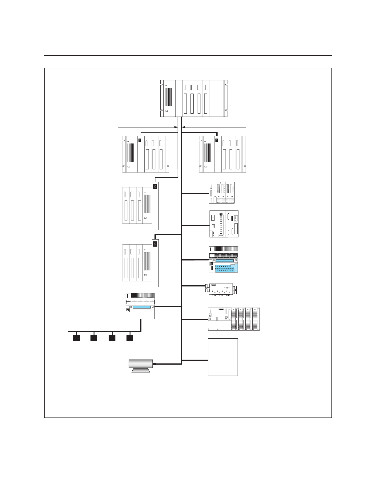
Figure 1 illustrates how the 505 and 500 PROFIBUS-DP RBCs fit into the
I/O architecture of a Series 505 system.
The physical and environmental specifications for the 505 PROFIBUS-DP
RBC are listed in the SIMATIC 545/555/575 System Manual.
2
SIMATIC 505/500 PROFIBUS-DP RBC User Manual
545/555/575
C
C
P
U
Series 505 Remote
I/O Channel
(1 Mbaud)
Series 505 Base with RBC
(PPX:505–6851–A/B RBC)
Series 500 Base with RBC
(PPX:500–51 14–A RBC)
Series 500 Base with 500
PROFIBUS-DP RBC
(PPX:500–6870 RBC)
PROFIBUS-DP
I/O Channel
(12 Mbaud)
R
B
C
R
B
C
R
Series 505 Base with
505 PROFIBUS-DP RBC
(PPX:505–6870 RBC)
ET200U
B
C
95U/PROFIBUS-DP
R
B
C
ET200B
Block I/O
ET200C
AS-Interface Master
S7 I/O
AS-Interface Bus
Allen-Bradley
Limit SW P/B Solenoid PE Cell
Siemens AC/DC
Motors and Drives
Festo
Metlore-Toledo
Data Logic
ABB
AEG-Modicon
Bosch
Turk
etc.
Third Party
Products
Notes:
The Series 505 remote I/O channel supports up to 15 Series 505/Series 500 remote bases.
The PROFIBUS-DP I/O channel supports up to 112 SIMATIC and third-party DP I/O slaves.
A 575–2104 CPU can support either the 505 I/O channel or the PROFIBUS-DP channel, but not both simultaneously.
The 545–1 103/–1105 CPUs support only the PROFIBUS-DP channel, up to 32 SIMATIC and third-party DP I/O slaves, with the
optional PROFIBUS-DP I/O annex card.
Figure 1 I/O Architecture for Series 505 System
SIMATIC 505/500 PROFIBUS-DP RBC User Manual
3
2 Setup and Installation
RBC Placement in
Base
The 505 PROFIBUS-DP RBC resides in a Series 505 base. Install it in the
second slot from the left, adjacent to the power supply module. See Figure 2.
P/S
I
I
I
I
I
I
I
505
RBC
I
/
/
/
/
O
O
O
O
O
/
/
/
/
O
O
O
Figure 2 Location of RBC in a Series 505 Base
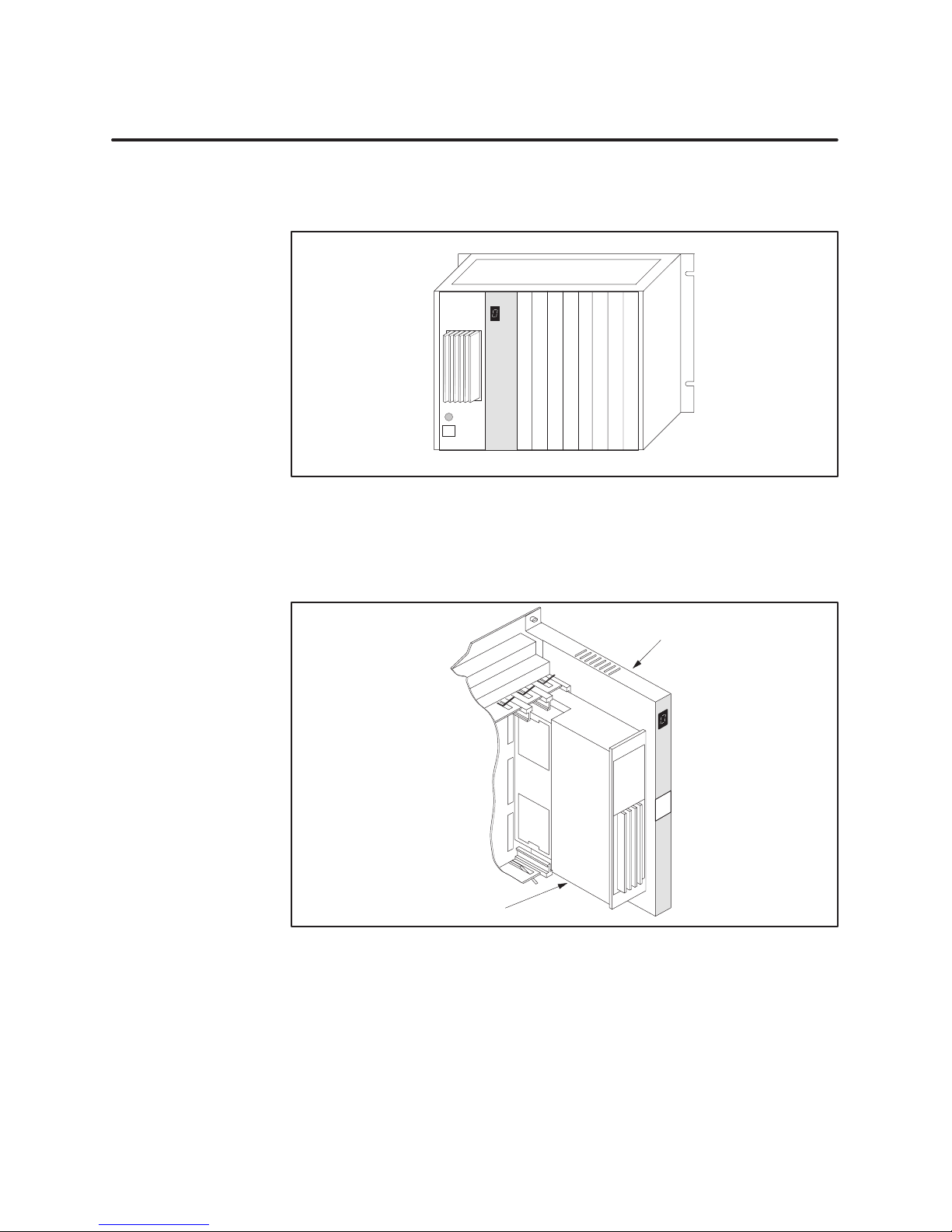
The 500 PROFIBUS-DP RBC resides in a Series 500 base. Install it in the
rightmost slot, adjacent to the power supply module. See Figure 3.
Series 500
Remote Base Controller
Power Supply
Figure 3 Location of RBC in a Series 500 Base
4
SIMATIC 505/500 PROFIBUS-DP RBC User Manual
Installing and
Removing the RBC
Use the following steps to install the 505–6870 RBC in a Series 505 base or
to install the 500–6870 RBC in a Series 500 base.
WARNING
!
Installing or removing an RBC from a powered-up base disrupts your process
and can damage the RBC. Disruption of your process can cause death or
serious injury to personnel, and/or damage to equipment.
Ensure that all power is disabled before installing or removing the RBC.
CAUTION
!
The RBC is sensitive to, and can be damaged by , electrostatic discharge.
Ensure that personnel make contact with a static-dissipative pad and/or wear a
grounded wrist strap when handling the RBC.
1. Verify that all jumper settings on the 505 RBC or the Off/Freeze toggle
switch on the 500 RBC are correct. See Section 4. It is advisable to set
the dipswitch options before installing the module. See Section 5.
2. Disconnect power to the base.
3. Position the RBC so that the bezel is facing you.
4. Grasp the top and bottom of the RBC.
5. Carefully push the RBC into the slot until it mates with the backplane
connector.
6. Tighten the top and bottom bezel screws.
CAUTION
!
Series 505 RBCs are not designed to be installed in VME bases. Doing so
results in damage to equipment.
Never attempt to install any Series 505 RBC in a VME base.
To remove the RBC, complete the following steps.
1. If attached, remove cables from the RBC.
2. Disconnect power to the base.
3. Loosen the top and bottom bezel screws.
4. Carefully pull the RBC from the base.
SIMATIC 505/500 PROFIBUS-DP RBC User Manual
5
3 RBC Ports
The 505 and 500 PROFIBUS-DP RBCs have two communication ports, an
RS-232 port and a PROFIBUS-DP I/O channel port.
RS-232 Port
When used with a Series 505 CPU, the RS-232 port is an interface to
programming devices that use software like TISOFT or other configuration
tools. To connect your RBC to a programming device/modem, use a standard
9-pin RS-232 serial cable that conforms at a minimum to the pinouts shown
in Figure 4. A standard cable that conforms to the minimum requirements
is available through Siemens; specify part number 2601094–8001.
Programming Device/Modem
Signal Ground (5)
Transmit Data (3)
Receive Data (2)
Pinouts
9
6
9-Pin, Female
D-Connector
5
3
2
1
Shield
RBC RS-232/423
Pinouts
5
9
6
Signal Ground
Transmit Data
3
Receive Data
2
1
Figure 4 RS-232 Serial Port, Minimum Cable Pinouts
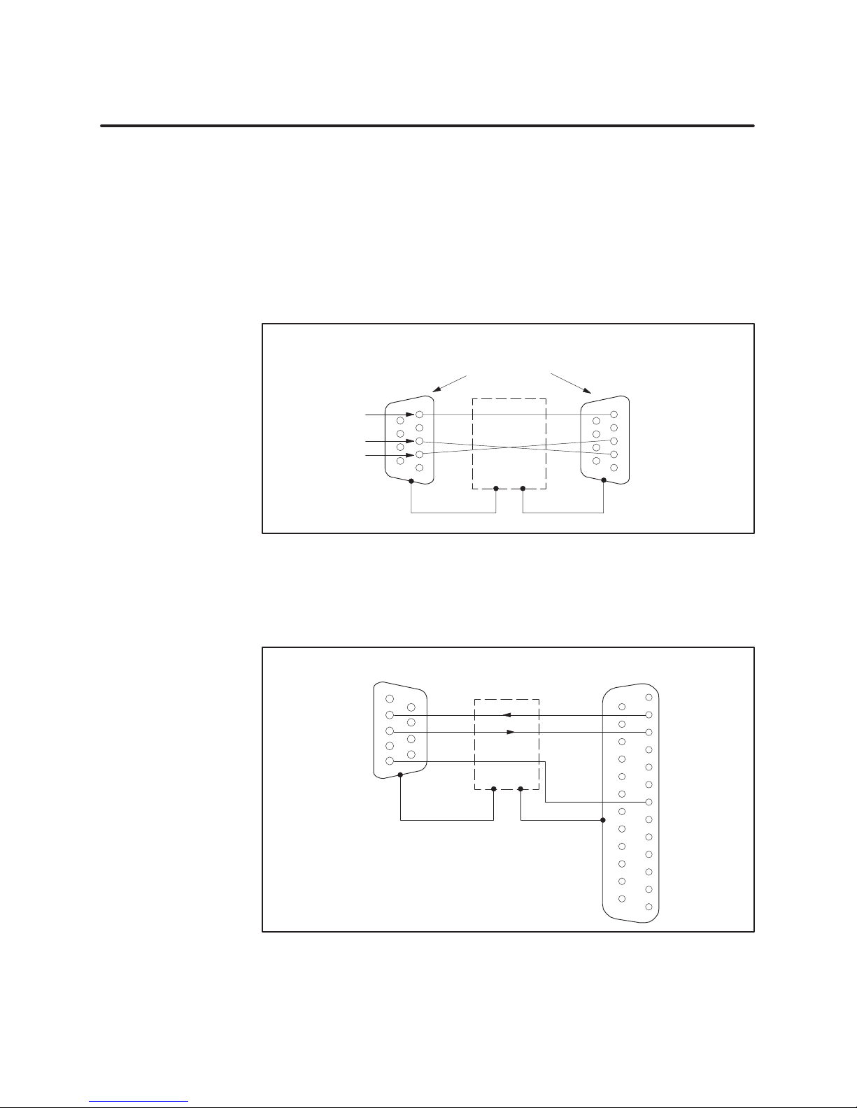
Figure 5 shows the 25-pin cable connector pinouts required for the 25-pin
female communications port on the 500 RBC.
Programming Device/Modem
Pinouts
1
Receive Data
Transmit Data
Signal Ground
6
2
7
3
8
4
9
5
9-Pin, Female
D-Connector
Shield
Note: You can use the standard Siemens programming
cable (#2601094–8001) with a 9-to-25-pin male adapter.
RBC RS-232/423
Pinouts
1
14
2
15
3
16
4
17
5
18
6
19
7
20
8
21
9
22
10
23
11
24
12
25
13
Transmit Data
Receive Data
Signal Ground
25-Pin, Male
D-Connector
Figure 5 500 RBC RS-232 Serial Communications Cable Pinouts
6
SIMATIC 505/500 PROFIBUS-DP RBC User Manual
 Loading...