

Page 1
Page 2
___________________
___________________
___________________
___________________
___________________
___________________
___________________
___________________
___________________
___________________
___________________
___________________
___________________
___________________
___________________
___________________
___________________
___________________
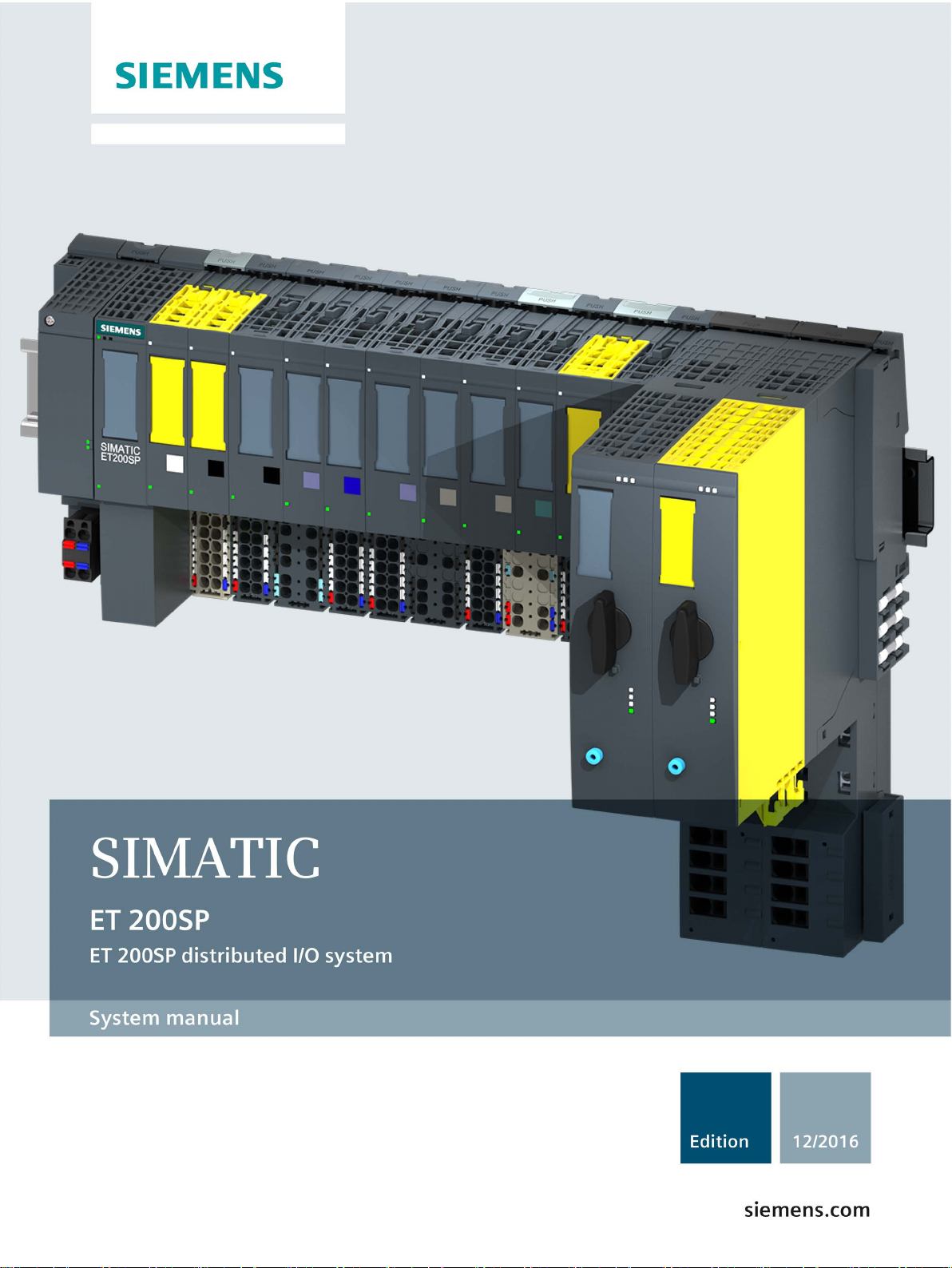
SIMATIC
ET 200SP
Distributed I/O system
System Manual
12/2016
A5E03576849
Preface
Guide to documentation
1
System overview
2
Application planning
3
Installation
4
Wiring
5
Configuring
6
Basics of program execution
7
Protection
8
Configuration control (option
handling)
9
Commissioning
10
SIMATIC memory card
11
Maintenance
12
Test functions and
eliminating problems
13
Technical specifications
14
Dimension drawings
A
Accessories/spare parts
B
Calculating the leakage
resistance
C
-AG
Page 3

Siemens AG
Division Digital Factory
Postfach 48 48
90026 NÜRNBERG
GERMANY
A5E03576849-AG
Ⓟ
Copyright © Siemens AG 2012 - 2016.
All rights reserved
Legal information
Warning notice system
DANGER
indicates that death or severe personal injury will result if proper precautions are not taken.
WARNING
indicates that death or severe personal injury may result if proper precautions are not taken.
CAUTION
indicates that minor personal injury can result if proper precautions are not taken.
NOTICE
indicates that property damage can result if proper precautions are not taken.
Qualified Personnel
personnel qualified
Proper use of Siemens products
WARNING
Siemens products may only be used for the applications described in the catalog and in the relevant technical
maintenance are required to ensure that the products operate safely and without any problems. The permissible
ambient conditions must be complied with. The information in the relevant documentation must be observed.
Trademarks
Disclaimer of Liability
This manual contains notices you have to observe in order to ensure your personal safety, as well as to prevent
damage to property. The notices referring to your personal safety are highlighted in the manual by a safety alert
symbol, notices referring only to property damage have no safety alert symbol. These notices shown below are
graded according to the degree of danger.
If more than one degree of danger is present, the warning notice representing the highest degree of danger will
be used. A notice warning of injury to persons with a safety alert symbol may also include a warning relating to
property damage.
The product/system described in this documentation may be operated only by
task in accordance with the relevant documentation, in particular its warning notices and safety instructions.
Qualified personnel are those who, based on their training and experience, are capable of identifying risks and
avoiding potential hazards when working with these products/systems.
Note the following:
documentation. If products and components from other manufacturers are used, these must be recommended
or approved by Siemens. Proper transport, storage, installation, assembly, commissioning, operation and
All names identified by ® are registered trademarks of Siemens AG. The remaining trademarks in this publication
may be trademarks whose use by third parties for their own purposes could violate the rights of the owner.
We have reviewed the contents of this publication to ensure consistency with the hardware and software
described. Since variance cannot be precluded entirely, we cannot guarantee full consistency. However, the
information in this publication is reviewed regularly and any necessary corrections are included in subsequent
editions.
for the specific
03/2017 Subject to change
Page 4

Preface
Preface
Purpose of the documentation
Basic knowledge required
Validity of the documentation
Definition
Conventions
Note
Notes conta
documentation to which you should pay particular attention.
This documentation provides important information on configuring, installing, wiring and
commissioning the ET 200SP distributed I/O system.
A basic knowledge of automation technology is required to understand the documentation.
This documentation applies to the distributed I/O system, ET 200SP.
In this document, " motor starter" always refers to all variants of the ET 200SP motor
starters.
Please pay particular attention to notes highlighted as follows:
in important information on the product, handling the product or on part of the
Distributed I/O system
4 System Manual, 12/2016, A5E03576849-AG
Page 5

Preface
Special information
WARNING
Hazardous Voltage
Can Cause Death, Serious Injury, or Property Damage.
Note
Important note for maintaining operational safety of your plant
Plants with safety
the part of the operator. Even suppliers are required to observe special measures during
product monitoring. For this reason, we inform you in the form of personal notifications about
product developments and features that are (or could be) relevant to operation of systems
from a safety perspective.
By subscribing to the appropriate notifications, you will ensure that you are always up
date
and ab
Log onto Industry Online Support. Go to the following links and, on the side, right click on
"email on update":
•
•
•
•
•
•
•
Note
When usin
SIMATIC Industrial Software SIMATIC Safety
(
Proper use of hardware products
This equipment is only allowed to be used for the applications described in the catalog and
in the technical description, and only in conjunction with non-Siemens equipment and
components recommended by Siemens.
Correct transport, storage, installation and assembly, as well as careful operation and
maintenance, are required to ensure that the product operates safely and without faults.
EU note: Start-up/commissioning is absolutely prohibited until it has been ensured that the
machine in which the component described here is to be installed fulfills the
regulations/specifications of Directive 2006/42/EC.
-related features are subject to special operational safety requirements on
le to make changes to your system, when necessary.
SIMATIC S7-300/S7-300F (https://support.industry.siemens.com/cs/ww/en/ps/13751)
SIMATIC S7-400/S7-400H/S7-400F/FH
(https://support.industry.siemens.com/cs/ww/en/ps/13828)
SIMATIC WinAC RTX (F) (https://support.industry.siemens.com/cs/ww/en/ps/13915)
SIMATIC S7-1500/SIMATIC S7-1500F
(https://support.industry.siemens.com/cs/ww/en/ps/13716)
SIMATIC S7-1200/SIMATIC S7-1200F
(https://support.industry.siemens.com/cs/ww/en/ps/13683)
Distributed I/O (https://support.industry.siemens.com/cs/ww/en/ps/14029)
STEP 7 (TIA Portal) (https://support.industry.siemens.com/cs/ww/en/ps/14667)
g F-CPUs in safety mode and fail-safe modules, observe the description of the
- Configuring and Programming
http://support.automation.siemens.com/WW/view/en/54110126) fail-safe system.
-to-
Distributed I/O system
System Manual, 12/2016, A5E03576849-AG
5
Page 6

Preface
Recycling and disposal
Security information
The products are low in pollutants and can be recycled. For environmentally compliant
recycling and disposal of your electronic waste, please contact a company certified for the
disposal of electronic waste.
Siemens provides products and solutions with industrial security functions that support the
secure operation of plants, systems, machines and networks.
In order to protect plants, systems, machines and networks against cyber threats, it is
necessary to implement – and continuously maintain – a holistic, state-of-the-art industrial
security concept. Siemens’ products and solutions only form one element of such a concept.
Customer is responsible to prevent unauthorized access to its plants, systems, machines
and networks. Systems, machines and components should only be connected to the
enterprise network or the internet if and to the extent necessary and with appropriate security
measures (e.g. use of firewalls and network segmentation) in place.
Additionally, Siemens’ guidance on appropriate security measures should be taken into
account. For more information about industrial security, please visit
(http://www.siemens.com/industrialsecurity).
Siemens’ products and solutions undergo continuous development to make them more
secure. Siemens strongly recommends to apply product updates as soon as available and to
always use the latest product versions. Use of product versions that are no longer supported,
and failure to apply latest updates may increase customer’s exposure to cyber threats.
To stay informed about product updates, subscribe to the Siemens Industrial Security RSS
Feed under (http://www.siemens.com/industrialsecurity).
Distributed I/O system
6 System Manual, 12/2016, A5E03576849-AG
Page 7

Preface
Siemens Industry Online Support
Product support
Application examples
Services
Forums
mySupport
Industry Mall
You can find current information on the following topics quickly and easily here:
●
All the information and extensive know-how on your product, technical specifications,
FAQs, certificates, downloads, and manuals.
●
Tools and examples to solve your automation tasks – as well as function blocks,
performance information and videos.
●
Information about Industry Services, Field Services, Technical Support, spare parts and
training offers.
●
For answers and solutions concerning automation technology.
●
Your personal working area in Industry Online Support for messages, support queries,
and configurable documents.
This information is provided by the Siemens Industry Online Support in the Internet
(http://www.siemens.com/automation/service&support).
The Industry Mall is the catalog and order system of Siemens AG for automation and drive
solutions on the basis of Totally Integrated Automation (TIA) and Totally Integrated Power
(TIP).
Catalogs for all the products in automation and drives are available on the Internet
(https://mall.industry.siemens.com).
Distributed I/O system
System Manual, 12/2016, A5E03576849-AG
7
Page 8

Table of contents
Preface ................................................................................................................................................... 4
1 Guide to documentation ........................................................................................................................ 13
2 System overview ................................................................................................................................... 17
3 Application planning .............................................................................................................................. 32
4 Installation ............................................................................................................................................ 54
2.1 What is the SIMATIC ET 200SP distributed I/O system? ...................................................... 17
2.2 What are fail-safe automation systems and fail-safe modules? ............................................ 20
2.3 How are SIMATIC Safety F-systems structured with ET 200SP? ......................................... 21
2.4 Components ........................................................................................................................... 25
3.1 Selecting the BaseUnit for I/O modules ................................................................................. 36
3.1.1 Digital, fail-safe, communication, technology or analog modules without temperature
measurement ......................................................................................................................... 36
3.1.2 Analog modules with temperature measurement .................................................................. 37
3.2 Selecting motor starters with a suitable BaseUnit ................................................................. 38
3.2.1 Selecting a BaseUnit for motor starters ................................................................................. 38
3.2.2 Selecting the motor starter ..................................................................................................... 39
3.2.3 Selecting accessories for motor starters ................................................................................ 40
3.3 Hardware configuration .......................................................................................................... 41
3.4 Forming potential groups ....................................................................................................... 43
3.4.1 Basics ..................................................................................................................................... 43
3.4.2 Forming potential groups with AC I/O modules ..................................................................... 47
3.4.3 Forming potential groups with fail-safe modules ................................................................... 49
3.4.4 Forming potential groups with motor starters ........................................................................ 50
3.5 Configuration examples for potential groups ......................................................................... 52
4.1 Basics ..................................................................................................................................... 54
4.2 Installation conditions for motor starters ................................................................................ 58
4.3 Mounting the CPU/interface module ...................................................................................... 60
4.4 Installing the CM DP communication module ........................................................................ 62
4.5 Mounting BaseUnits for I/O modules ..................................................................................... 64
4.6 Mounting and dismantling BaseUnits for motor starters ........................................................ 66
4.7 Installing the server module ................................................................................................... 68
4.8 Mounting further accessories for motor starters .................................................................... 69
4.8.1 Mounting the cover for the 500 V AC infeed bus ................................................................... 69
4.8.2 Mounting the mechanical bracket for the BaseUnit ............................................................... 71
4.8.3 Mounting the BU cover .......................................................................................................... 74
Distributed I/O system
8 System Manual, 12/2016, A5E03576849-AG
Page 9

Table of contents
5 Wiring ................................................................................................................................................... 75
5.1 Rules and regulations for operation ........................................................................................ 75
5.2 Additional rules and regulations for the operation of the ET 200SP with fail-safe
modules .................................................................................................................................. 77
5.2.1 Safety extra low voltage for fail-safe modules and fail-safe motor starters ............................ 77
5.2.2 Requirements for sensors and actuators for fail-safe modules and fail-safe motor
starters .................................................................................................................................... 78
5.2.3 Crosstalk of digital input/output signals .................................................................................. 81
5.3 Additional rules and instructions for operation with motor starters ......................................... 81
5.3.1 Protection against short circuit ................................................................................................ 81
5.4 Operating the ET 200SP on grounded incoming supply ........................................................ 82
5.5 Electrical configuration of the ET 200SP ................................................................................ 85
5.6 Wiring rules ............................................................................................................................. 87
5.7 Wiring BaseUnits for I/O modules ........................................................................................... 90
5.8 Connecting cable shields for I/O modules .............................................................................. 92
5.9 Wiring BaseUnits for motor starters ........................................................................................ 94
5.10 Connecting the 3DI/LC module for the motor starter .............................................................. 97
5.11 Connecting the supply voltage to the CPU/interface module ................................................. 99
5.12 Connecting interfaces for communication............................................................................. 101
5.12.1 Connecting PROFINET IO to the CPU/interface module via the bus adapter BA
2xRJ45 .................................................................................................................................. 101
5.12.2 Connecting PROFINET IO to the CPU/interface module via the BA 2xFC BusAdapter ...... 104
5.12.3 Connecting PROFINET IO to the CPU/interface module via BA 2xSCRJ BusAdapter ....... 108
5.12.4 Connecting PROFINET IO to the interface module via the BA SCRJ/RJ45 BusAdapter .... 111
5.12.5 Connecting PROFINET IO to the interface module via the BA SCRJ/FC BusAdapter ........ 113
5.12.6 Connecting PROFINET IO to the interface module via the BA 2xLC BusAdapter ............... 115
5.12.7 Connecting PROFINET IO to the interface module via the BA LC/RJ45 BusAdapter ......... 118
5.12.8 Connecting PROFINET IO to interface module via BA LC/FC BusAdapter ......................... 120
5.12.9 Connecting PROFINET IO (port P3) to the CPU .................................................................. 121
5.12.10 Connecting the PROFIBUS DP interface to the interface module/communications
module CM DP ...................................................................................................................... 123
5.13 Inserting I/O modules / motor starters and BU covers .......................................................... 124
5.14 Mounting/disassembly of motor starters ............................................................................... 126
5.14.1 Mounting the fan ................................................................................................................... 126
5.14.2 Mounting/disassembly of motor starters ............................................................................... 127
5.14.3 3DI/LC module ...................................................................................................................... 130
5.15 Labeling ET 200SP ............................................................................................................... 133
5.15.1 Factory markings .................................................................................................................. 133
5.15.2 Optional markings ................................................................................................................. 135
5.15.3 Applying color identification labels ........................................................................................ 137
5.15.4 Applying labeling strips ......................................................................................................... 138
5.15.5 Applying reference identification labels ................................................................................ 139
Distributed I/O system
System Manual, 12/2016, A5E03576849-AG
9
Page 10

Table of contents
6 Configuring .......................................................................................................................................... 140
7 Basics of program execution ................................................................................................................ 150
8 Protection ............................................................................................................................................ 163
9 Configuration control (option handling) ................................................................................................. 172
6.1 Configuring ET 200SP ......................................................................................................... 140
6.2 Configuring the CPU ............................................................................................................ 143
6.2.1 Reading out the configuration .............................................................................................. 143
6.2.2 Addressing ........................................................................................................................... 145
6.2.3 Process images and process image partitions .................................................................... 147
6.2.3.1 Process image - overview .................................................................................................... 147
6.2.3.2 Automatically updating process image partitions ................................................................. 148
6.2.3.3 Update process image partitions in the user program ......................................................... 148
6.3 Configuring the interface module ......................................................................................... 149
7.1 Events and OBs ................................................................................................................... 150
7.2 CPU overload behavior ........................................................................................................ 153
7.3 Asynchronous instructions ................................................................................................... 155
8.1 Overview of the protective functions of the CPU ................................................................. 163
8.2 Configuring access protection for the CPU .......................................................................... 164
8.3 Using the user program to set additional access protection ................................................ 167
8.4 Know-how protection ........................................................................................................... 167
8.5 Copy protection .................................................................................................................... 170
9.1 Configuring ........................................................................................................................... 175
9.2 Creating the control data record .......................................................................................... 177
9.2.1 Introduction .......................................................................................................................... 177
9.2.2 Control data record for an ET 200SP CPU .......................................................................... 179
9.2.3 Control data record for an interface module ........................................................................ 180
9.2.4 Feedback data record for interface modules ....................................................................... 184
9.2.5 Data records and functions .................................................................................................. 186
9.3 Transferring control data record in the startup program of the CPU ................................... 187
9.4 Behavior during operation .................................................................................................... 191
9.5 Examples of configuration control ........................................................................................ 192
Distributed I/O system
10 System Manual, 12/2016, A5E03576849-AG
Page 11

Table of contents
10 Commissioning ................................................................................................................................... 197
11 SIMATIC memory card ........................................................................................................................ 229
10.1 Overview ............................................................................................................................... 197
10.2 Commissioning the ET 200SP for PROFINET IO ................................................................ 199
10.2.1 ET 200SP CPU as an IO controller ...................................................................................... 199
10.2.2 ET 200SP CPU as an I-device ............................................................................................. 201
10.2.3 ET 200SP as an IO device ................................................................................................... 203
10.3 Commissioning the ET 200SP on PROFIBUS DP ............................................................... 204
10.3.1 ET 200SP as a DP master .................................................................................................... 204
10.3.2 ET 200SP as I-slave ............................................................................................................. 206
10.3.3 ET 200SP as a DP slave ...................................................................................................... 208
10.4 Startup of the ET 200SP with empty slots ............................................................................ 209
10.5 Removing/inserting a SIMATIC memory card on the CPU................................................... 209
10.6 Operating modes of the CPU ................................................................................................ 211
10.6.1 STARTUP mode ................................................................................................................... 211
10.6.2 STOP mode .......................................................................................................................... 214
10.6.3 RUN mode ............................................................................................................................ 215
10.6.4 Operating mode transitions ................................................................................................... 215
10.7 CPU memory reset ............................................................................................................... 217
10.7.1 Automatic memory reset ....................................................................................................... 218
10.7.2 Manual memory reset ........................................................................................................... 219
10.8 Reassigning parameters during operation ............................................................................ 220
10.9 Identification and maintenance data ..................................................................................... 221
10.9.1 Reading out and entering I&M data ...................................................................................... 221
10.9.2 Data record structure for I&M data ....................................................................................... 223
10.10 Shared commissioning of projects ........................................................................................ 225
10.11 Backing up and restoring the CPU configuration .................................................................. 225
10.11.1 Overview ............................................................................................................................... 225
11.1 SIMATIC memory card - overview ........................................................................................ 229
11.2 Setting the card type ............................................................................................................. 234
11.3 Data transfer with SIMATIC memory cards .......................................................................... 235
Distributed I/O system
System Manual, 12/2016, A5E03576849-AG
11
Page 12

Table of contents
12 Maintenance ........................................................................................................................................ 236
13 Test functions and eliminating problems ............................................................................................... 259
14 Technical specifications ....................................................................................................................... 267
A Dimension drawings ............................................................................................................................. 284
B Accessories/spare parts ....................................................................................................................... 286
C Calculating the leakage resistance ....................................................................................................... 290
Glossary .............................................................................................................................................. 292
Index ................................................................................................................................................... 308
12.1 Removing and inserting I/O modules/motor starters ........................................................... 236
12.2 Changing the type of an I/O module .................................................................................... 239
12.3 Replacing an I/O module ..................................................................................................... 241
12.4 Replacing a motor starter ..................................................................................................... 242
12.5 Replacing the terminal box on the BaseUnit ........................................................................ 243
12.6 Firmware update .................................................................................................................. 245
12.7 Resetting CPU/interface module (PROFINET) to factory settings ...................................... 250
12.7.1 Resetting the CPU to factory settings .................................................................................. 250
12.7.2 Resetting interface module (PROFINET IO) to factory settings .......................................... 253
12.7.3 Resetting the interface module (PROFINET IO) to factory settings with a RESET
button ................................................................................................................................... 255
12.8 Reaction to faults in fail-safe modules and fail-safe motor starters ..................................... 256
12.9 Maintenance and repair ....................................................................................................... 258
12.10 Warranty ............................................................................................................................... 258
13.1 Test functions ....................................................................................................................... 259
13.2 Reading out/saving service data .......................................................................................... 265
14.1 Standards, approvals and safety notes ............................................................................... 268
14.2 Electromagnetic compatibility .............................................................................................. 274
14.3 Electromagnetic compatibility of fail-safe modules .............................................................. 277
14.4 Shipping and storage conditions .......................................................................................... 279
14.5 Mechanical and climatic environmental conditions .............................................................. 279
14.6 Insulation, protection class, degree of protection and rated voltage ................................... 281
14.7 Use of the ET 200SP in zone 2 potentially explosive atmospheres .................................... 283
A.1 Shield connector .................................................................................................................. 284
A.2 Labeling strip ........................................................................................................................ 284
A.3 Reference identification labels ............................................................................................. 285
B.1 Lightning protection and overvoltage protection for fail-safe modules ................................ 289
Distributed I/O system
12 System Manual, 12/2016, A5E03576849-AG
Page 13
1
Basic information
Device information
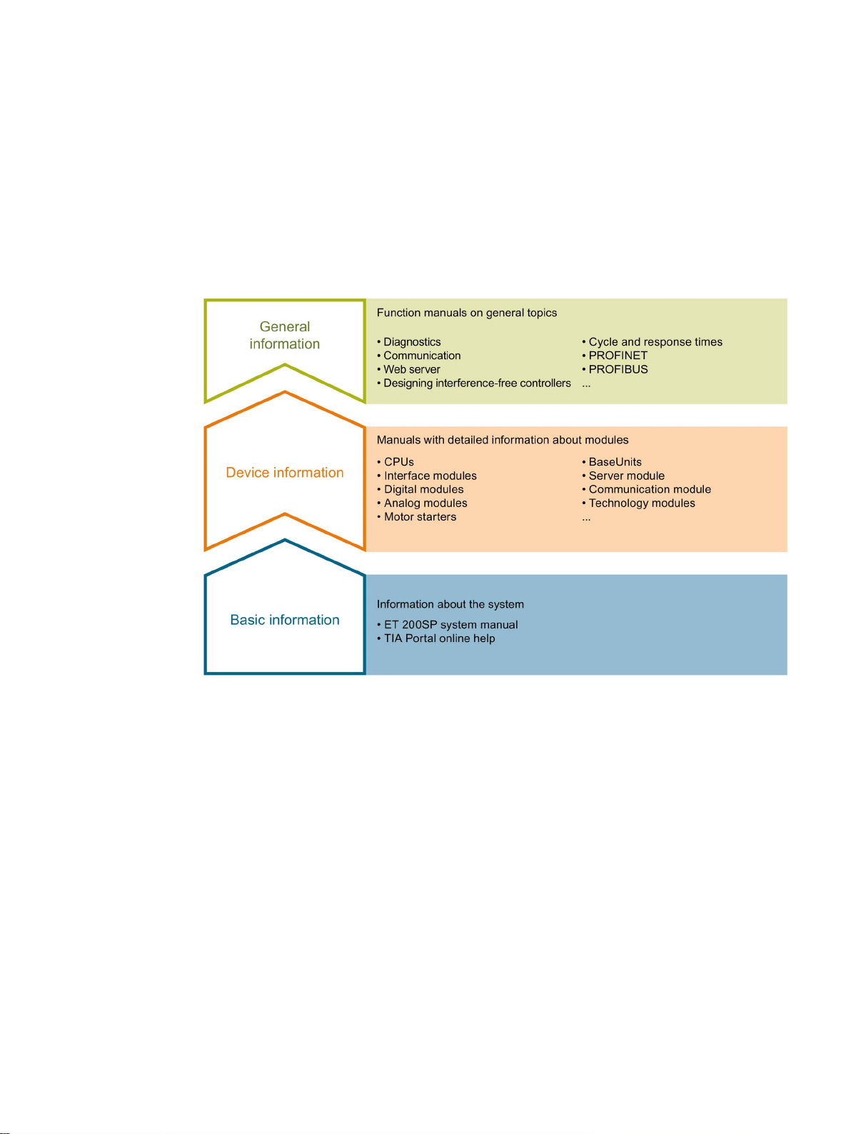
The documentation for the SIMATIC ET 200SP distributed I/O system is arranged into three
areas.
This arrangement enables you to access the specific content you require.
The system manual describes in detail the configuration, installation, wiring and
commissioning of the SIMATIC ET 200SP. distributed I/O system. The STEP 7 online help
supports you in the configuration and programming.
Product manuals contain a compact description of the module-specific information, such as
properties, wiring diagrams, characteristics and technical specifications.
Distributed I/O system
System Manual, 12/2016, A5E03576849-AG
13
Page 14

Guide to documentation
General information
Manual Collection ET 200SP
"mySupport"
"mySupport" - Documentation
The function manuals contain detailed descriptions on general topics regarding the SIMATIC
ET 200SP distributed I/O system, e.g. diagnostics, communication, Web server, motion
control and OPC UA.
You can download the documentation free of charge from the Internet
(http://w3.siemens.com/mcms/industrial-automation-systems-simatic/en/manual-
overview/tech-doc-et200/Pages/Default.aspx).
Changes and supplements to the manuals are documented in a Product Information.
You can download the product information free of charge from the Internet
(https://support.industry.siemens.com/cs/us/en/view/73021864).
The Manual Collection contains the complete documentation on the SIMATIC ET 200SP
distributed I/O system gathered together in one file.
You can find the Manual Collection on the Internet
(http://support.automation.siemens.com/WW/view/en/84133942).
With "mySupport", your personal workspace, you make the most of your Industry Online
Support.
In "mySupport" you can store filters, favorites and tags, request CAx data and put together
your personal library in the Documentation area. Furthermore, your data is automatically
filled into support requests and you always have an overview of your current requests.
You need to register once to use the full functionality of "mySupport".
You can find "mySupport" in the Internet (https://support.industry.siemens.com/My/ww/en).
In the Documentation area of "mySupport", you have the possibility to combine complete
manuals or parts of them to make your own manual.
You can export the manual in PDF format or in an editable format.
You can find "mySupport" - Documentation in the Internet
(http://support.industry.siemens.com/My/ww/en/documentation).
Distributed I/O system
14 System Manual, 12/2016, A5E03576849-AG
Page 15

Guide to documentation
"mySupport" - CAx Data
Application examples
TIA Selection Tool
In the CAx Data area of "mySupport", you can have access the latest product data for your
CAx or CAe system.
You configure your own download package with a few clicks.
In doing so you can select:
● Product images, 2D dimension drawings, 3D models, internal circuit diagrams, EPLAN
macro files
● Manuals, characteristics, operating manuals, certificates
● Product master data
You can find "mySupport" - CAx Data in the Internet
(http://support.industry.siemens.com/my/ww/en/CAxOnline).
The application examples support you with various tools and examples for solving your
automation tasks. Solutions are shown in interplay with multiple components in the system separated from the focus in individual products.
You can find the application examples on the Internet
(https://support.industry.siemens.com/sc/ww/en/sc/2054).
With the TIA Selection Tool, you can select, configure and order devices for Totally
Integrated Automation (TIA).
This tool is the successor of the SIMATIC Selection Tool and combines the known
configurators for automation technology into one tool.
With the TIA Selection Tool, you can generate a complete order list from your product
selection or product configuration.
You can find the TIA Selection Tool on the Internet
(http://w3.siemens.com/mcms/topics/en/simatic/tia-selection-tool).
Distributed I/O system
System Manual, 12/2016, A5E03576849-AG
15
Page 16

Guide to documentation
SIMATIC Automation Tool
PRONETA
You can use the SIMATIC Automation Tool to run commissioning and maintenance activities
simultaneously on various SIMATIC S7 stations as a bulk operation independently of the TIA
Portal.
The SIMATIC Automation Tool provides a multitude of functions:
● Scanning of a PROFINET/Ethernet network and identification of all connected CPUs
● Address assignment (IP, subnet, gateway) and station name (PROFINET device) to a
CPU
● Transfer of the data and the programming device/PC time converted to UTC time to the
module
● Program download to CPU
● Operating mode switchover RUN/STOP
● Localization of the CPU by means of LED flashing
● Reading out CPU error information
● Reading the CPU diagnostic buffer
● Reset to factory settings
● Updating the firmware of the CPU and connected modules
You can find the SIMATIC Automation Tool on the Internet
(https://support.industry.siemens.com/cs/ww/en/view/98161300).
With SIEMENS PRONETA (PROFINET network analysis), you analyze the plant network
during commissioning. PRONETA features two core functions:
● The topology overview independently scans PROFINET and all connected components.
● The IO check is a fast test of the wiring and the module configuration of a system.
You can find SIEMENS PRONETA on the Internet
(https://support.industry.siemens.com/cs/ww/en/view/67460624).
Distributed I/O system
16 System Manual, 12/2016, A5E03576849-AG
Page 17
2
2.1
What is the SIMATIC ET 200SP distributed I/O system?
SIMATIC ET 200SP
Customer benefits of the system
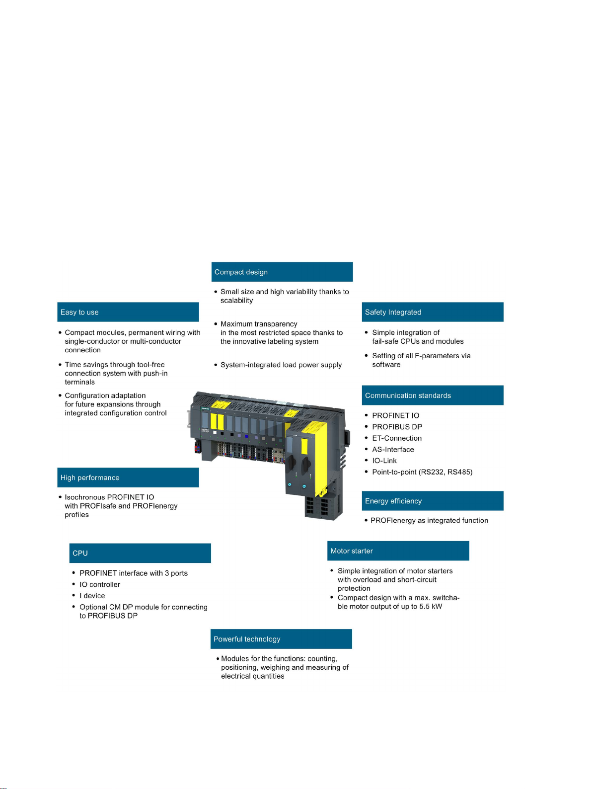
SIMATIC ET 200SP is a scalable and highly flexible distributed I/O system for connecting
process signals to a higher-level controller via a fieldbus.
Figure 2-1 SIMATIC ET 200SP distributed I/O system - Customer benefits
Distributed I/O system
System Manual, 12/2016, A5E03576849-AG
17
Page 18

System overview
Area of application
Configuration
2.1 What is the SIMATIC ET 200SP distributed I/O system?
Thanks to its multifunctionality, the SIMATIC ET 200SP distributed I/O system is suitable for
a wide range of applications. Its scalable design allows you to tailor your configuration to
local requirements. Different CPUs/interface modules are available for connection to
PROFINET IO or PROFIBUS DP.
SIMATIC ET 200SP with CPU allows intelligent pre-processing to relieve the higher-level
controller. The CPU can also be used as standalone device.
By using fail-safe CPUs, you can implement applications for safety engineering.
Configuration and programming of your safety program takes place the same way as for
standard CPUs.
A wide range of I/O modules rounds off the product range.
SIMATIC ET 200SP is designed with degree of protection IP20 and is intended for
installation in a control cabinet.
The SIMATIC ET 200SP distributed I/O system is installed on a mounting rail. It consists of:
● CPU/interface module
● Up to 64 I/O modules, which can be plugged into BaseUnits in any combination
● Up to 31 motor starters
● A server module that completes the configuration of the ET 200SP.
Distributed I/O system
18 System Manual, 12/2016, A5E03576849-AG
Page 19
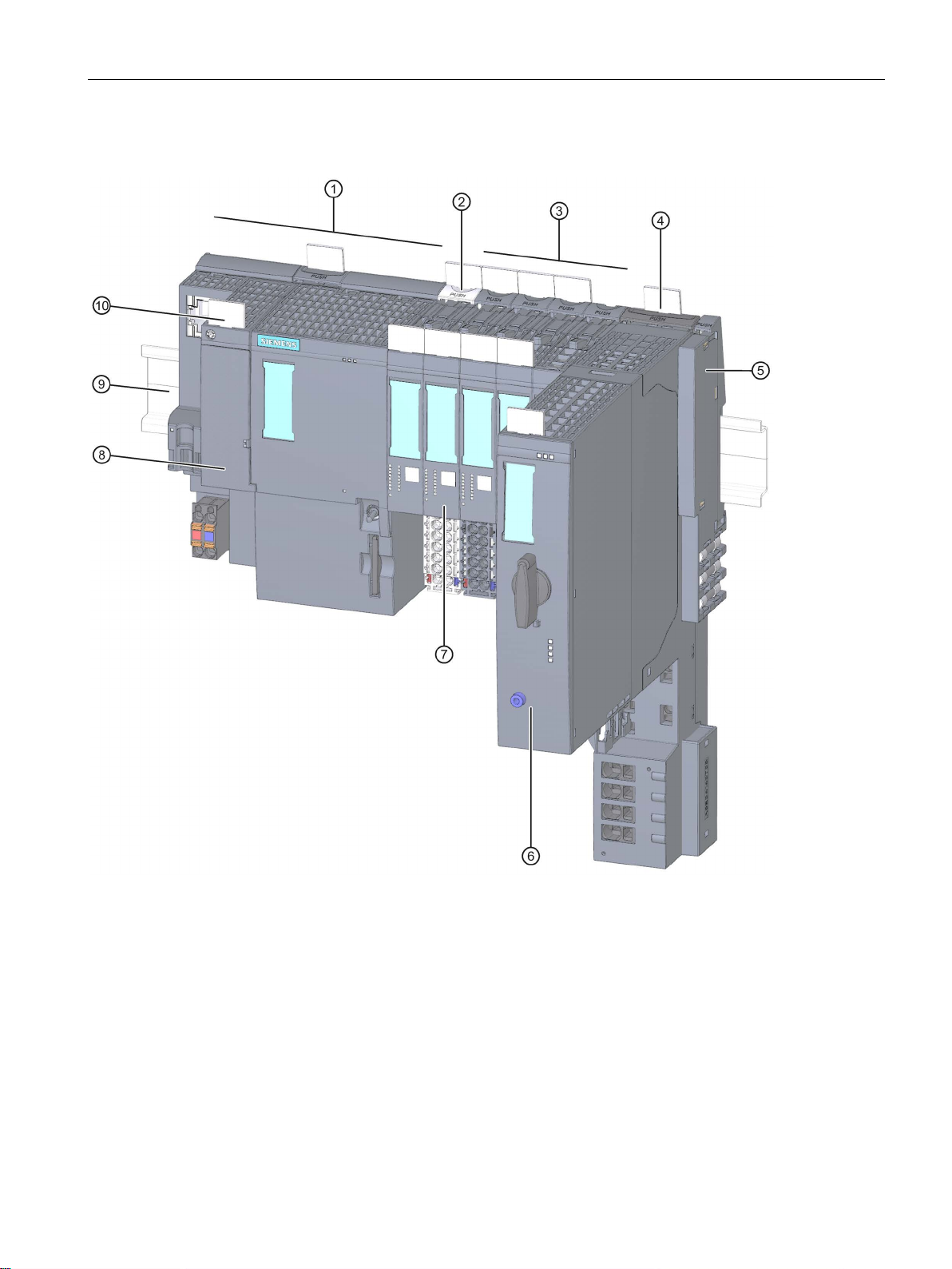
System overview
Configuration example
①
CPU/interface module
②
Light-colored BaseUnit BU..D with infeed of supply voltage
③
Dark-colored BaseUnits BU..B for extending the potential group
④
BaseUnit for motor starter
⑤
Server module (included in the scope of delivery of the CPU/interface module)
⑥
ET 200SP motor starter
⑦
I/O module
⑧
BusAdapter
⑨
Mounting rail
⑩
Reference identification label
2.1 What is the SIMATIC ET 200SP distributed I/O system?
Figure 2-2 Configuration example of the ET 200SP
Distributed I/O system
System Manual, 12/2016, A5E03576849-AG
19
Page 20

System overview
2.2
What are fail-safe automation systems and fail-safe modules?
Fail-safe automation systems
Safety Integrated
Fail-safe modules
Fail-safe motor starters
Area of application of ET 200SP with fail-safe I/O modules
2.2 What are fail-safe automation systems and fail-safe modules?
Fail-safe automation systems (F-systems) are used in systems with higher safety
requirements. F-systems control processes and ensure that they are in a safe state
immediately after shutdown. In other words, F-systems control processes in which an
immediate shutdown does not endanger persons or the environment.
Safety Integrated is the integrated safety concept for automation and drive technology from
Siemens.
Proven technologies and systems from automation technology are used for safety systems.
Safety Integrated includes the complete safety sequence, ranging from sensor, actuator and
fail-safe modules right through to the controller, including safety-related communication via
standard fieldbuses. Drives and controllers handle safety tasks in addition to their actual
functions.
The key difference between fail-safe modules (F-modules) and standard modules is that they
have an internal two-channel design. This means the two integrated processors monitor
each other, automatically test the input and output circuits, and switch the fail-safe module to
a safe state in the event of a fault.
The F-CPU communicates with a fail-safe module via the safety-related PROFIsafe bus
profile.
Fail-safe motor starters enable safety-related tripping of motor loads. Fail-safe motor starters
are not PROFIsafe nodes. Motor starters operate together with the fail-safe modules of the
ET 200SP system.
By using the ET 200SP distributed I/O system with fail-safe I/O modules, you are replacing
conventional safety engineering configurations. This includes the replacement of switching
devices for emergency STOP, protective door monitors, two-hand operation, etc.
Distributed I/O system
20 System Manual, 12/2016, A5E03576849-AG
Page 21
System overview
2.3
How are SIMATIC Safety F-systems structured with ET 200SP?
SIMATIC Safety F-system with ET 200SP
Fail-safe ET 200SP I/O modules
ET 200SP fail-safe motor starters
2.3 How are SIMATIC Safety F-systems structured with ET 200SP?
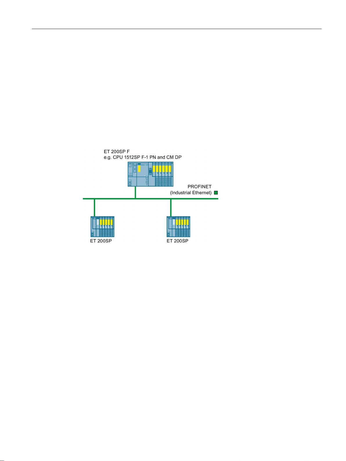
The figure below shows an example of a configuration for a SIMATIC Safety F-system with
ET 200SP distributed I/O system and PROFINET IO. The PROFINET IO lines can be set up
with copper cable, fiber-optic cable or WLAN.
Fail-safe I/O modules and non-fail-safe I/O modules can be combined in an ET 200SP
configuration.
The fail-safe IO controller (F-CPU) exchanges safety-related and non-safety-related data
with fail-safe and non-fail-safe ET 200SP modules.
Figure 2-3 Fail-safe SIMATIC Safety automation system (sample configuration)
The following fail-safe I/O modules are available for the ET 200SP distributed I/O system:
● Fail-safe power modules are used to supply the potential group load voltage and for the
safety-related tripping of the load voltage for non-fail-safe output modules.
● Fail-safe digital input modules detect the signal states of safety-related sensors and send
the relevant safety frames to the F-CPU.
● Fail-safe digital output modules are suitable for safety-related shutdown procedures with
short circuit and cross-circuit protection up to the actuator.
Fail-safe motor starters are suitable for safety-related tripping of motor loads.
Distributed I/O system
System Manual, 12/2016, A5E03576849-AG
21
Page 22
System overview
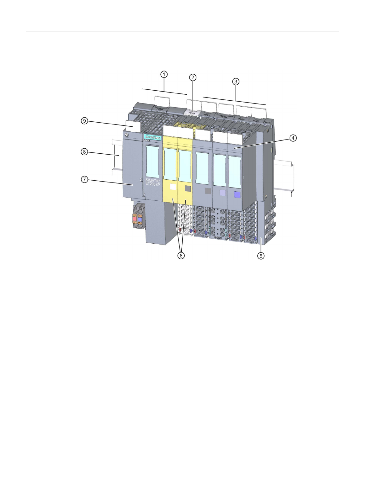
Example of a configuration with fail-safe I/O modules
①
Interface module
②
Light-colored BaseUnitBU..D with infeed of supply voltage
③
Dark-colored BaseUnitsBU..B for conducting the potential group further
④
I/O module
⑤
Server module (ships with the interface module)
⑥
Fail-safe I/O modules
⑦
BusAdapter
⑧
Mounting rail
⑨
Reference identification label
2.3 How are SIMATIC Safety F-systems structured with ET 200SP?
Figure 2-4 Example of a configuration of the ET 200SP with fail-safe I/O modules
Distributed I/O system
22 System Manual, 12/2016, A5E03576849-AG
Page 23

System overview
Hardware and software requirements
Note
Configuration of
G
Use in safety mode only
2.3 How are SIMATIC Safety F-systems structured with ET 200SP?
ET 200SP fail-safe modules are supported by interface modules IM155-6PN BA, firmware
V3.2 or higher, IM155-6PN ST, firmware V1.1.1 or higher, IM155-6PN HF, firmware V2.0 or
higher, IM155-6PN HS firmware V4.0 or higher and IM155-6DP HF, firmware V1.0 or higher.
You require the STEP 7 Safety Advanced option package, V12 or higher including HSP 54,
for configuration and programming of the ET 200SP fail-safe modules with the SIMATIC
Safety fail-safe system.
You require the F-Configuration Pack V5.5 SP10 for configuration and programming of the
ET 200SP fail-safe modules with the Distributed Safety fail-safe system.
You require the F-Configuration Pack V5.5 SP12 for configuration and programming of the
ET 200SP fail-safe modules with the F/FH Systems fail-safe system.
ET 200SP fail-safe motor starters are supported by interface modules IM155-6PN BA,
firmware V3.2 or higher, IM155-6PN ST, firmware V3.1 or higher, IM155-6PN HF, firmware
V3.1 or higher and IM155-6DP HF firmware V3.0 or higher.
You require SIMATIC Step 7 V14 or higher for configuration and programming of ET 200SP
fail-safe motor starters. The F-Configuration Pack is not needed for configuration and
programming of the ET 200SP fail-safe motor starter.
SD file (GSDML).
Safety mode is the F-I/O operating mode that allows safety-related communication using
safety frames.
Safety mode of motor starters is characterized by the fail-safe digital input (F-DI) and
availability of the 24 V power supply.
You can only use the ET 200SP fail-safe I/O modules in safety mode. They cannot be used
in non-fail-safe mode.
ET 200SP motor starters, SIMATIC Step 7 V13 or higher, is possible with a
Distributed I/O system
System Manual, 12/2016, A5E03576849-AG
23
Page 24

System overview
Achievable safety classes
Safety class in safety mode
According to IEC 61508
According to ISO 13849-1:2006
SIL2
Category 3
(PL) Performance Level d
SIL3
Category 3
(PL) Performance Level e
Additional information
2.3 How are SIMATIC Safety F-systems structured with ET 200SP?
The fail-safe modules are equipped with integrated safety functions for safety mode.
You can achieve the safety classes of the table below:
● With the appropriate parameter assignment of the safety functions in STEP 7
● With a specific combination of fail-safe and non-fail-safe I/O modules
● With a special arrangement and wiring of the sensors and actuators
Table 2- 1 Safety classes that can be achieved with ET 200SP in safety mode
SIL3 Category 4 (PL) Performance Level e
You will find the use cases and wiring for the relevant safety class in the manuals of the failsafe I/Os and the fail-safe motor starters.
Distributed I/O system
24 System Manual, 12/2016, A5E03576849-AG
Page 25
System overview
2.4
Components
Basic components of the ET 200SP distributed I/O system
Basic component
Function
Figure
2.4 Components
Table 2- 2 Basic components of the ET 200SP
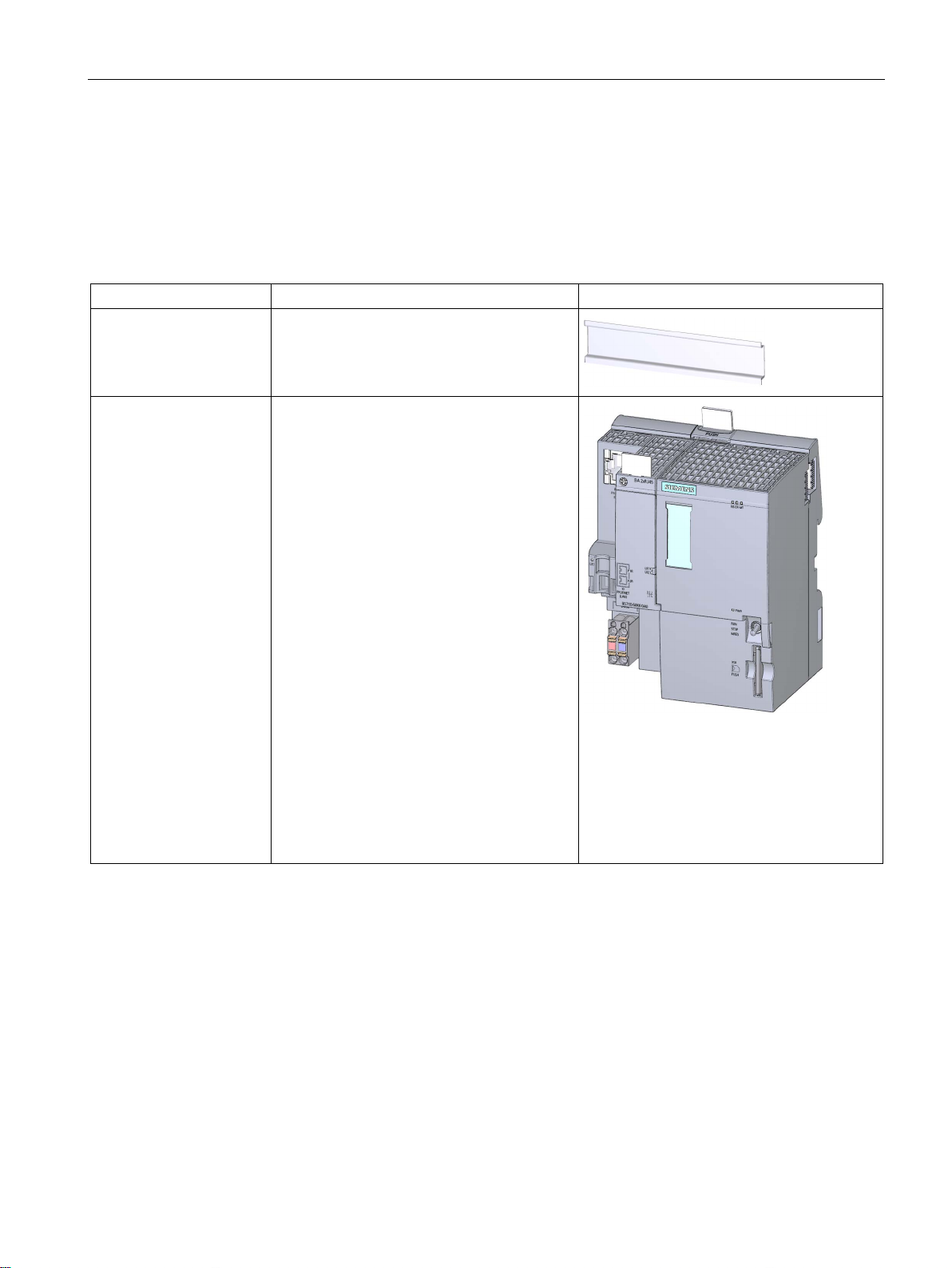
Mounting rail in accordance with EN 60715
CPU/Fail-safe CPU The (F) CPU:
The mounting rail is the rack of the ET 200SP.
The ET 200SP is installed on the mounting
rail. The mounting rail is 35 mm high.
• Runs the user program. The F-CPU also
runs the safety program.
• Can be used as an IO controller or I-
Device on PROFINET IO or as a
standalone CPU
• Links the ET 200SP to the IO devices or
the IO controller
• Exchanges data with the I/O modules via
the backplane bus.
Additional CPU functions:
• Communication via PROFIBUS DP (the
CPU can be used as a DP master or DP
slave in combination with the CM DP
communication module)
• Integrated Web server
• Integrated technology
• Integrated trace functionality
• Integrated system diagnostics
• Integrated safety
• Safety mode (when using fail-safe CPUs)
Distributed I/O system
System Manual, 12/2016, A5E03576849-AG
25
Page 26
System overview
Basic component
Function
Figure
2.4 Components
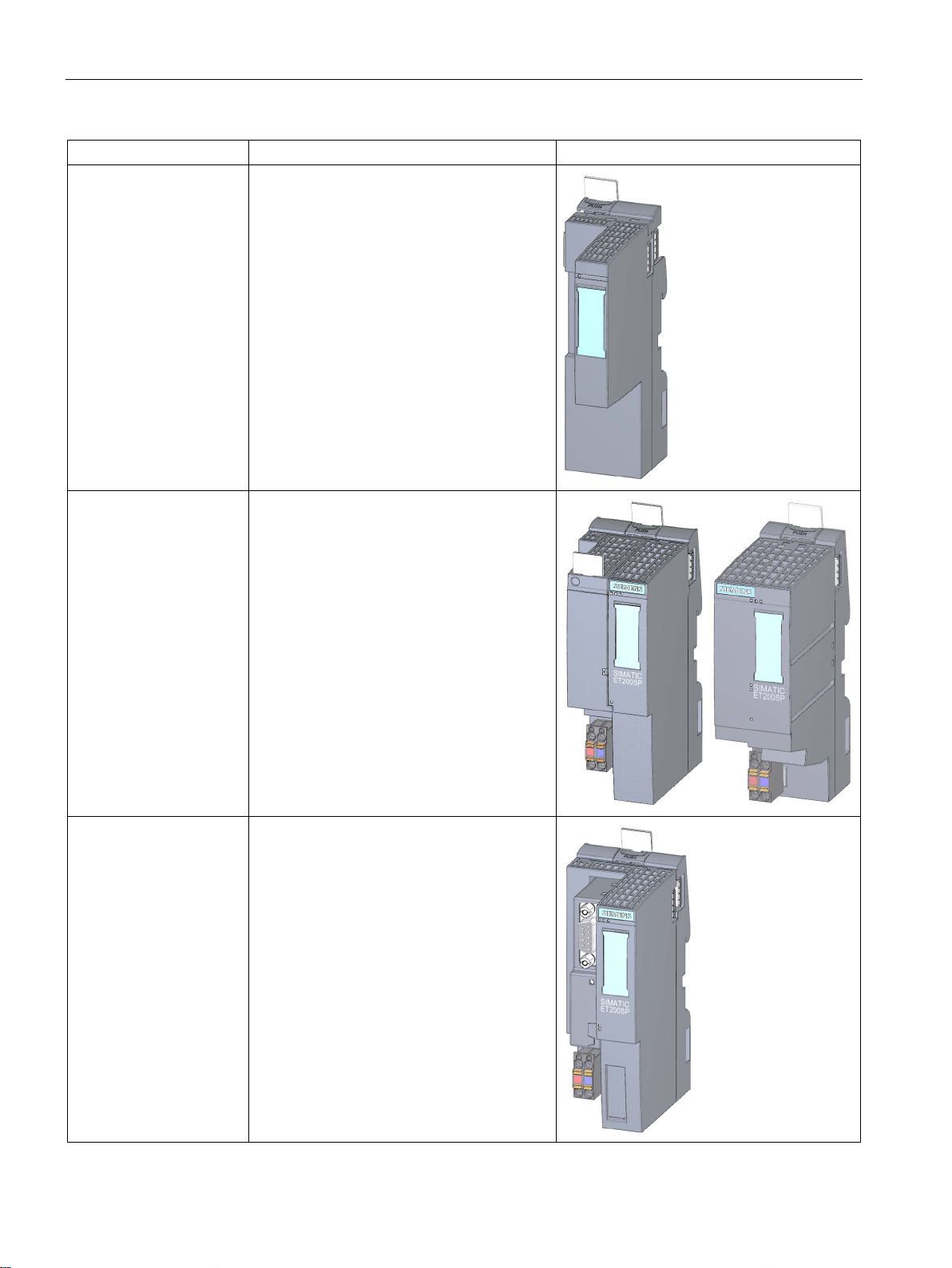
Communication module
CM DP
Interface module for
PROFINET IO
The communication module CM DP
• Connects the CPU with PROFIBUS DP
• The bus connection is an RS485 interface
The interface module:
• Can be used as IO device on
PROFINET IO
• Links the ET 200SP with the IO controller
• Exchanges data with the I/O modules via
the backplane bus.
Interface module for
PROFIBUS DP
Distributed I/O system
The interface module:
• Can be used as DP slave on PROFIBUS
DP
• Links the ET 200SP with the DP master
• Exchanges data with the I/O modules via
the backplane bus.
26 System Manual, 12/2016, A5E03576849-AG
Page 27
System overview
Basic component
Function
Figure
2.4 Components
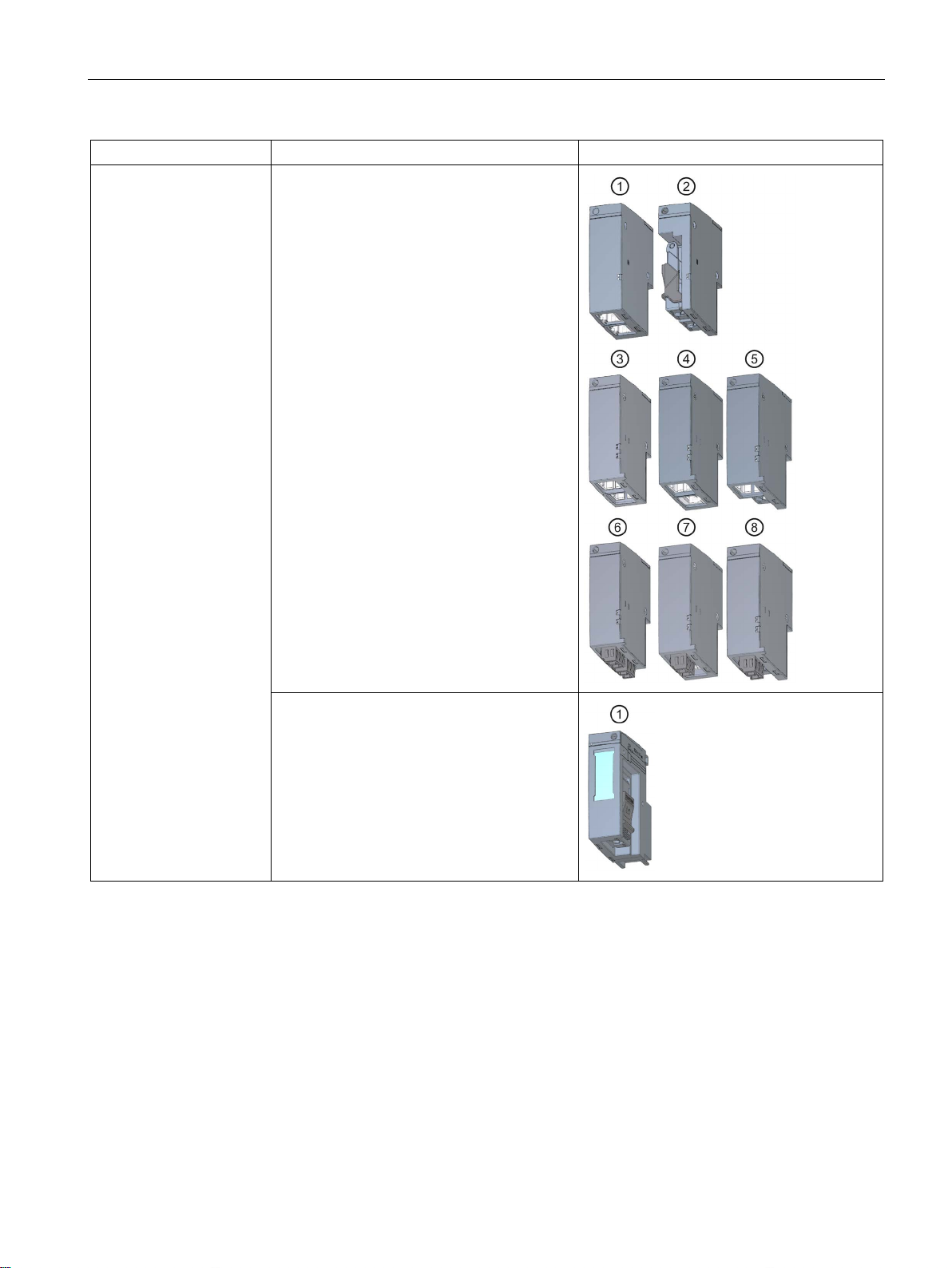
BusAdapter The BusAdapters allow free selection of the
connection technology for PROFINET IO. The
following versions are available for
PROFINET CPU/interface modules:
• For standard RJ45 connector (BA 2×RJ45)
①
• For direct connection of the bus cable
(BA 2×FC) ②
• For POF/PCF fiber-optic cable (BA
2xSCRJ) ③
• As media converter for POF/PCF fiber-
optic cable ⇔ standard RJ45 plug (BA
SCRJ/RJ45)
• As media converter for POF/PCF fiber-
optic cable ⇔ direct connection of the bus
cable (BA SCRJ/FC)
• For glass fiber-optic cable (BA 2xLC)
• As media converter for glass fiber-optic
cable ⇔ standard RJ45 plug (BA LC/RJ45)
④
⑤
⑥
⑦
• As media converter for glass fiber-optic
cable ⇔ direct connection of the bus cable
(BA LC/FC)
⑧
For mixed ET 200SP/ET 200AL configuration,
you require the BusAdapter BA-Send 1xFC
① (plugged into the BaseUnit BU-Send).
Connect the bus cable for ET-Connection to
the BusAdapter BA-Send 1xFC.
Distributed I/O system
System Manual, 12/2016, A5E03576849-AG
27
Page 28
System overview
Basic component
Function
Figure
2.4 Components
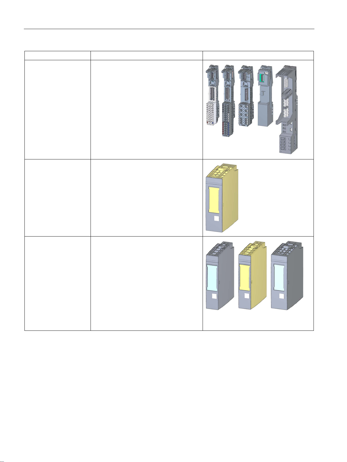
BaseUnit The BaseUnits provide the electrical and me-
chanical connection of the ET 200SP modules. Place the I/O modules or the motor
starter onto the BaseUnits.
Suitable BaseUnits are available for each of
the different requirements (see Selecting the
BaseUnit for I/O modules (Page 36)).
Fail-safe power module The fail-safe power module allows the safety-
related shutdown of digital output modules /
fail-safe digital output modules.
I/O module / fail-safe I/O
module
The I/O module determines the function at the
terminals. The controller detects the current
process state via the connected sensors and
actuators, and triggers the corresponding
reactions. I/O modules are divided into the
following module types:
• Digital input (DI, F-DI)
• Digital output (DQ, F-DQ, F-RQ)
• Analog input (AI)
• Analog output (AQ)
• Technology module (TM)
• Communication module (CM)
Distributed I/O system
28 System Manual, 12/2016, A5E03576849-AG
Page 29
System overview
Basic component
Function
Figure
2.4 Components
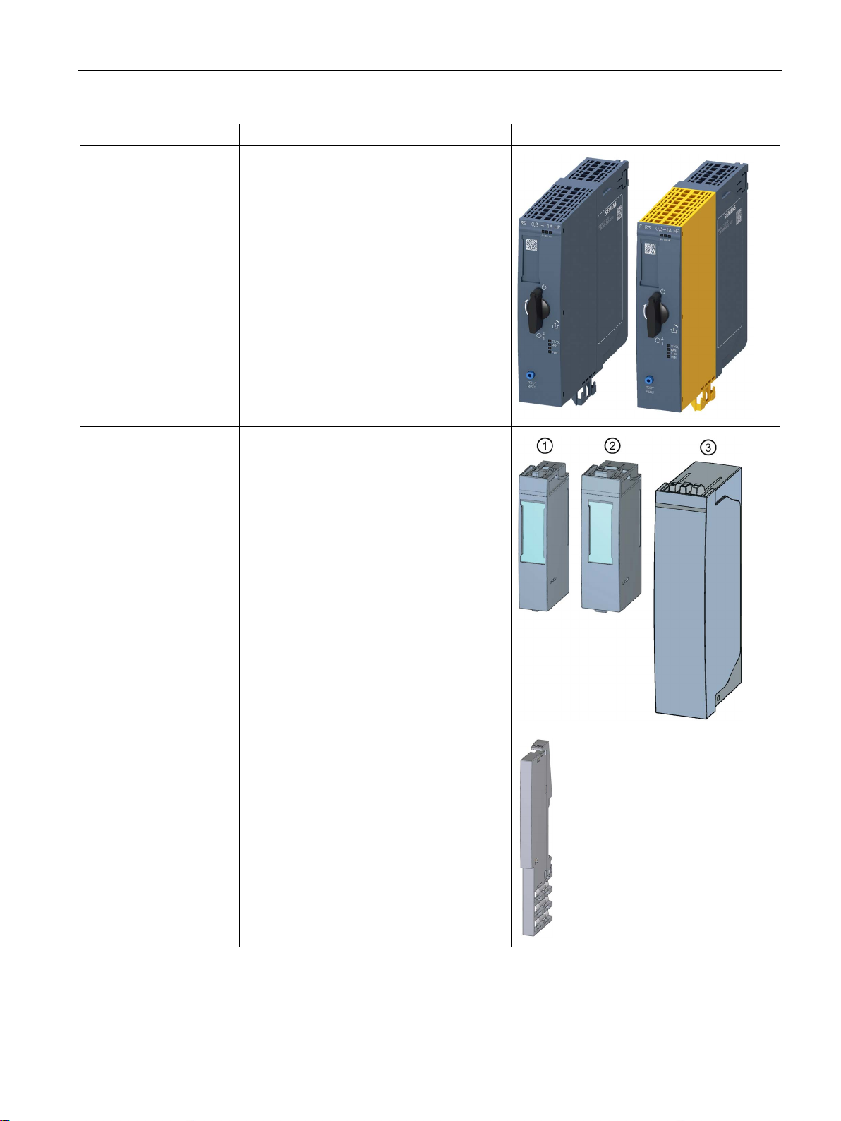
Motor starter/fail-safe
motor starter
BU cover Insert the BU cover on the BaseUnits:
The motor starter is a switching and protection
device for 1-phase and 3-phase loads.
The motor starter is available as a direct-online and reversing starter.
• Whose slots are not occupied by I/O mod-
ules /motor starters
• Whose slots have been reserved for future
expansion (as empty slots).
You can keep a reference identification label
for the planned I/O module inside the BU
cover.
There are three versions:
• For BaseUnits with a width of 15 mm
• For BaseUnits with a width of 20 mm
• For BaseUnits of motor starters with a
width of 30 mm ③
①
②
Server module The server module completes the configura-
Distributed I/O system
System Manual, 12/2016, A5E03576849-AG
tion of the ET 200SP. The server module
includes holders for 3 spare fuses
(5 × 20 mm).
The server module ships with the
CPU/interface module.
29
Page 30
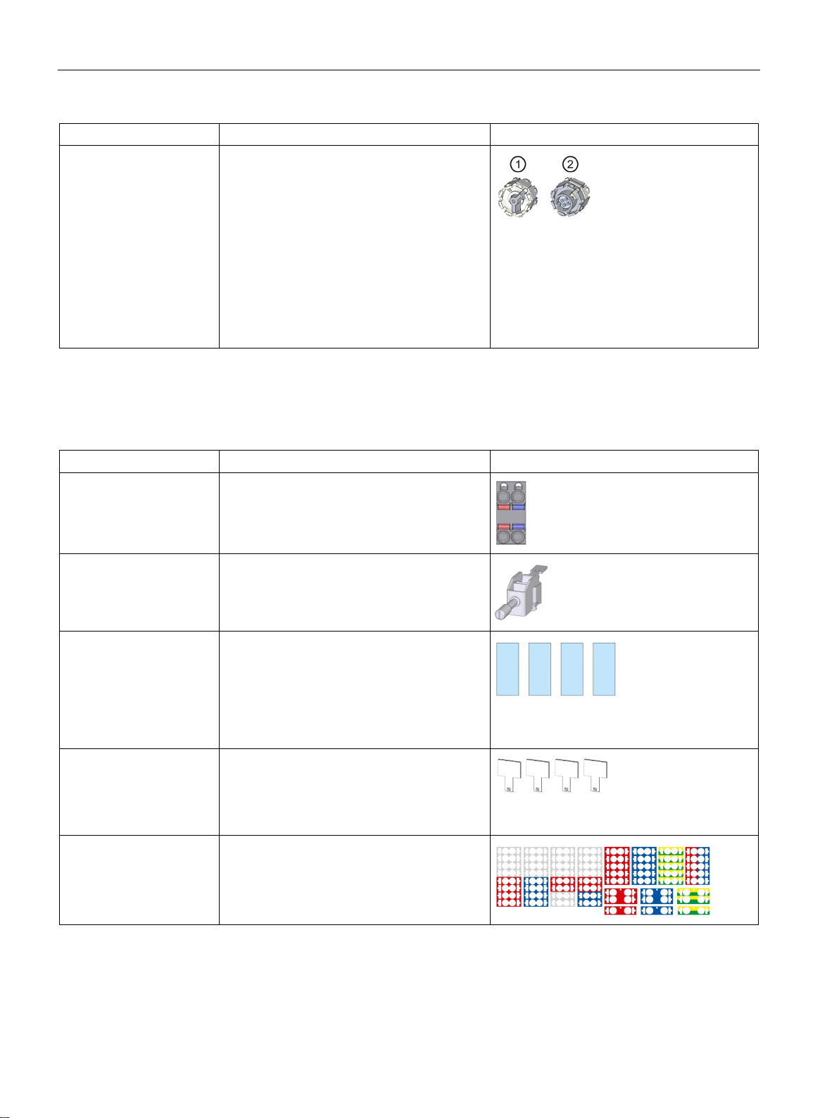
System overview
Basic component
Function
Figure
Accessories of the ET 200SP distributed I/O system
Accessories
Function
Figure
printers.
(Page 286).
2.4 Components
Coding element The coding element codes the I/O module
with the BaseUnit.
There are two versions:
• Mechanical coding element
the coding
• Electronic coding element ②: This version
also has an electronic, rewritable memory
for module-specific configuration data
(such as the F-destination address for failsafe modules, parameter data for the IO
link master).
①: Ensures
Table 2- 3 Accessories of the ET 200SP
24 V DC connector Applying the 24 V DC supply at the connector
and connection with the IM.
Shield connection The shield connection allows the low-
impedance contacting of cable shields with
minimum installation times.
Labeling strips Attach the labeling strips to the modules for
system-specific labeling of the ET 200SP. The
labeling strips can be printed.
The labeling strips can be ordered as accessories (Page 286) on a roll for thermal transfer
printers or as DIN A4 format sheets for laser
Reference identification
labels
Color identification labels The color identification labels are module-
The labels enable the reference identification
labeling of the ET 200SP components.
The labels can be ordered on a mat for thermal transfer and inkjet printers as accessories
specific and can be ordered for the process
terminals, AUX terminals and additional terminals as accessories (Page 286).
Distributed I/O system
30 System Manual, 12/2016, A5E03576849-AG
Page 31
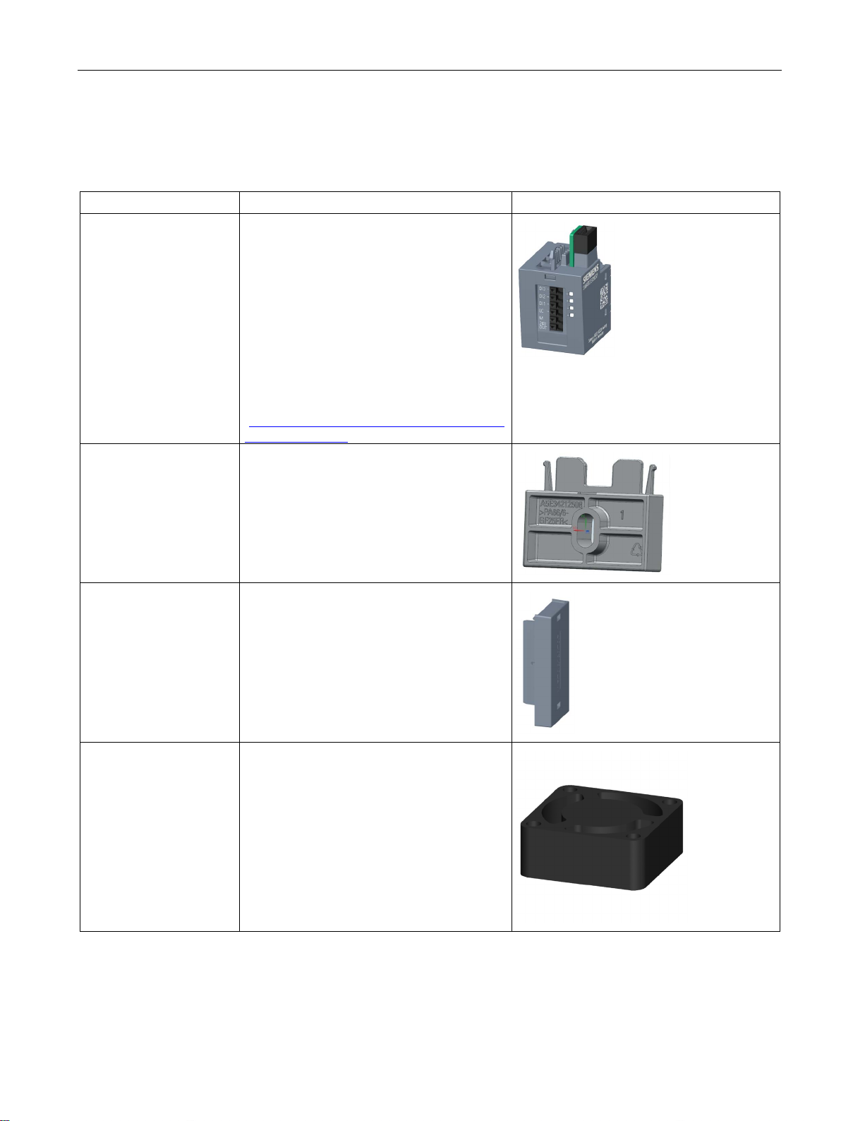
System overview
Accessories of the SIMATIC ET 200SP motor starters
Accessories
Function
Figure
n/view/109479973).
2.4 Components
Table 2- 4 SIMATIC ET 200SP motor starter accessories
3DI/LC module The optional 3DI/LC module has three digital
inputs and one LC input. For reasons of operational safety, input LC is permanently set to
manual local mode. By parameterizing the
inputs DI1 - DI3 with motor CLOCKWISE or
motor COUNTER-CLOCKWISE, you can
control the motor in manual local mode.
The functions of the 3DI/LC module are not
relevant to functional safety.
Detailed information on the functions when
using a 3DI/LC module can be found in the
Manual
(https://support.industry.siemens.com/cs/ww/e
Mechanical bracket for
BaseUnit
Infeed bus cover For finger-safe termination of the infeed bus,
Fan You can use the motor starter at higher ambi-
Use the mechanical bracket for additional
fixing of the motor starter. You can use the
mechanical bracket on 7.5 mm and 15 mm
mounting rails.
use the cover.
ent temperatures if a fan is installed.
Distributed I/O system
System Manual, 12/2016, A5E03576849-AG
31
Page 32

3
Overview
Note
You will find a complete overview of the possibilities of combining BaseUnits and I/O
modules
system (
Selecting a BaseUnit
I/O module
(example)
Examples of suitable I/O modules for BU types
I/O module (example)
BaseUnit
A0
A0
A0
with-
out
A1
with
A1
The BaseUnits (BU) are classified according to different types. Every BaseUnit type is
distinguished by characteristics that match certain I/O modules and motor starters (see the
following table and graphics).
You recognize the BU type for an I/O module by the last two digits of an I/O module's article
number.
/motor starters in the Product information for documentation of the ET 200SP I/O
http://support.automation.siemens.com/WW/view/en/73021864).
Table 3- 1 Selecting a suitable BaseUnit for I/O modules
BU type A0
See Digital, fail-safe,
communication, technology or analog
modules without temperature measurement (Page 36)
BU type A1
See Analog modules
with temperature
measurement
(Page 37)
Digital, fail-safe,
technology or communication module
• 6ES7...
• 24 V DC
• 15 mm wide
Analog module
temperature
measurement**
• 6ES7...A1
• 24 V DC
• 15 mm wide
Analog module
temperature measurement*
• 6ES7...A1
• 24 V DC
• 15 mm wide
DI 16×24VDC ST
(6ES7131-6BH00-0B
AI 4xU/I 2-wire ST
(6ES7134-6HD00-0B
AI 4×RTD/TC 2-/3-/4wire HF
(6ES7134-6JD00-0CA1)
BU15-P16+A0+2D
)
(6ES7193-6BP00-0D
)
BU15P16+A0+2D/T(6ES71936BP00-0D
)
)
Distributed I/O system
32 System Manual, 12/2016, A5E03576849-AG
Page 33

Application planning
Selecting a BaseUnit
I/O module
(example)
Examples of suitable I/O modules for BU types
I/O module (example)
BaseUnit
B0
B0
B0
B1
B1
B1
C0
C1
C1
C1
C1
C1
D0
D0
D0
F0
* For compensation of the reference junction temperature for thermocouples. The BU type A1 is r
** Analog modules
BU type B0
(BU..B, dark-colored
BaseUnit)
BU type B1
(BU..B, dark-colored
BaseUnit)
BU type C0
(BU..D, light-colored
BaseUnit)
BU type C1
(BU..B, dark-colored
BaseUnit)
BU type D0 AI Energy Meter
BU type F0 F-
Digital output module
with relay
• 6ES7...
• Up to 230 V AC
• 20 mm wide
Digital modules
• 6ES7...
• up to 230 V AC
• 20 mm wide
Fail-safe power module
• 6ES7...
• 24 V DC
• 20 mm wide
CM ASi Master ST/FCM AS-i Safety ST
• 6ES7...
• Up to 30 V DC
• 20 mm wide
F-CM AS-i Safety ST
• 6ES7...
• Up to 30 V DC
• 20 mm wide
• 6ES7...
• Up to 400 V AC/
480 V AC
• 20 mm wide
RQ 1×24VDC/24..230
VAC/5A
• 6ES7...
• Up to 230 V AC
• 20 mm wide
RQ 4×120VDC230VAC/5A NO ST
(6ES7132-6HD00-0B
DI 4×120..230VAC ST
(6ES7131-6FD00-0B
CM AS-i Master ST
(3RK7137-6SA00-0B
F-CM AS-i Safety ST
(3RK7136-6SC00-0B
AI Energy Meter 480VAC
ST
(6ES7134-6PA20-0B
FRQ 1×24VDC/24..230VA
C/5A
(6ES7136-6RA00-0BF0)
)
)
BU20-P12+A4+0B
(6ES7193-6BP20-0B
)
BU20-P12+A0+4B
(6ES7193-6BP20-0B
BU20-P6+A2+4D
)
(6ES7193-6BP20-0DC0)
BU20-P6+A2+4B
)
(6ES7193-6BP20-0B
BU20-P12+A0+0B
(6ES7193-6BP00-0B
BU20-P8+A4+0B
(6E7193-6BP20-0BF0)
)
)
)
)
Distributed I/O system
System Manual, 12/2016, A5E03576849-AG
quired if measuring the reference junction temperature with an internal temperature sensor or if
you need the 2×5 additional terminals.
with temperature measurement can be plugged on BU type A0.
e-
33
Page 34

Application planning
Selecting the BaseUnit
BU-30MS1
BU-30MS2
BU-30MS3
BU-30MS4
BU-30MS5
BU-30MS6
24 V infeed
x x
500 V infeed
x x x F-DI terminals
x
x
Motor starters
HF
0AB00-0CP0
HF
0AC00-0CP0
HF
0AD00-0CP0
HF
0AE00-0CP0
HF
0BB00-0CP0
HF
0BC00-0CP0
HF
0BD00-0CP0
HF
0CB00-0CP0
HF
0CD00-0CP0
12A HF
0CE00-0CP0
HF
0DB00-0CP0
HF
0DC00-0CP0
HF
0DD00-0CP0
12A HF
0DE00-0CP0
* The F-DI terminals have no function with this combination.
Table 3- 2 BaseUnit for motor starters
DS 0.3 - 1A
DS 0.9 - 3A
DS 2.8 - 9A
DS 4.0 - 12A
RS 0.3 - 1A
RS 0.9 - 3A
RS 2.8 - 9A
RS 4.0 - 12A
HF
F-DS 0.3 - 1A
F-DS 0.9 - 3A
HF
F-DS 2.8 - 9A
3RK1308-
3RK1308-
3RK1308-
3RK1308-
3RK1308-
3RK1308-
3RK1308-
3RK13080BE00-0CP0
3RK1308-
3RK13080CC00-0CP0
3RK1308-
x x x x x* x*
x x x x x* x*
x x x x x* x*
x x x x x* x*
x x x x x* x*
x x x x x* x*
x x x x x* x*
x x x x x* x*
x x x x x x
x x x x x x
x x x x x x
F-DS 4.0 -
F-RS 0.3 - 1A
F-RS 0.9 - 3A
F-RS 2.8 - 9A
F-RS 4.0 -
Distributed I/O system
3RK1308-
3RK1308-
3RK1308-
3RK1308-
3RK1308-
34 System Manual, 12/2016, A5E03576849-AG
x x x x x x
x x x x x x
x x x x x x
x x x x x x
x x x x x x
Page 35

Application planning
Additional information
3.1 Selecting the BaseUnit for I/O modules
Additional information on the functional assignment of the terminals and on the associated
BaseUnits can be found in one of the following manuals:
● Manual for the relevant I/O module
(http://support.automation.siemens.com/WW/view/en/55679691/133300)
● Manual BaseUnits (http://support.automation.siemens.com/WW/view/en/59753521)
● Motor starter (https://support.industry.siemens.com/cs/ww/en/view/109479973) manual
Distributed I/O system
System Manual, 12/2016, A5E03576849-AG
35
Page 36
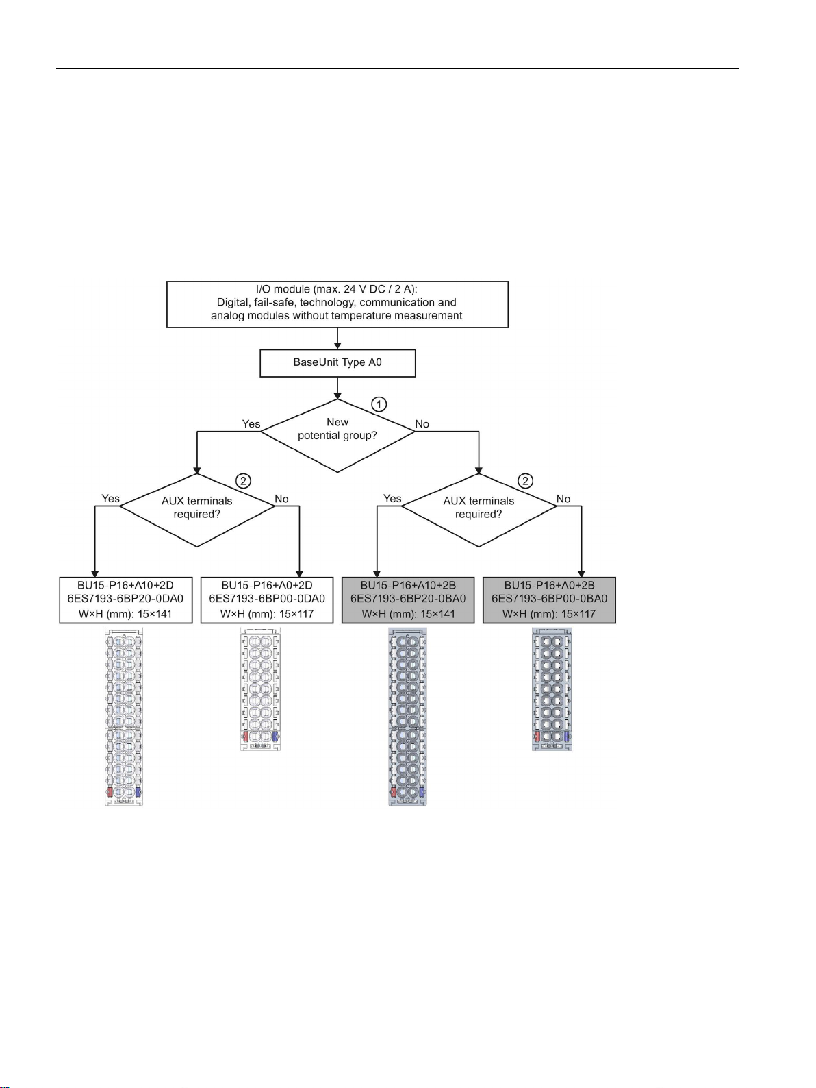
Application planning
3.1
Selecting the BaseUnit for I/O modules
3.1.1
Digital, fail-safe, communication, technology or analog modules without temperature measurement
Selection of a suitable BaseUnit
①
Dark-colored BaseUnit: Conduction of the internal power and AUX buses from the adjacent module on the left.
②
Example: Multiple cable connection for DI 8×24VDC ST
3.1 Selecting the BaseUnit for I/O modules
Light-colored BaseUnit: Configuration of a new potential group, electrical isolation from adjacent module on the left.
The first BaseUnit of the ET 200SP is usually a light-colored BaseUnit for feeding the supply voltage L+.
Exception: If you insert an AC I/O module or an AI Energy Meter as the first I/O module, the first BaseUnit in the
ET 200SP configuration can be a dark-colored BaseUnit. The requirement is that you use a CPU or IM 155-6 (as of
V3.0).
AUX terminal: 10 internally bridged terminals for individual use up to 24 V DC/10 A or as protective conductors.
Figure 3-1 Digital, fail-safe, communication, technology or analog modules without temperature measurement
Distributed I/O system
36 System Manual, 12/2016, A5E03576849-AG
Page 37
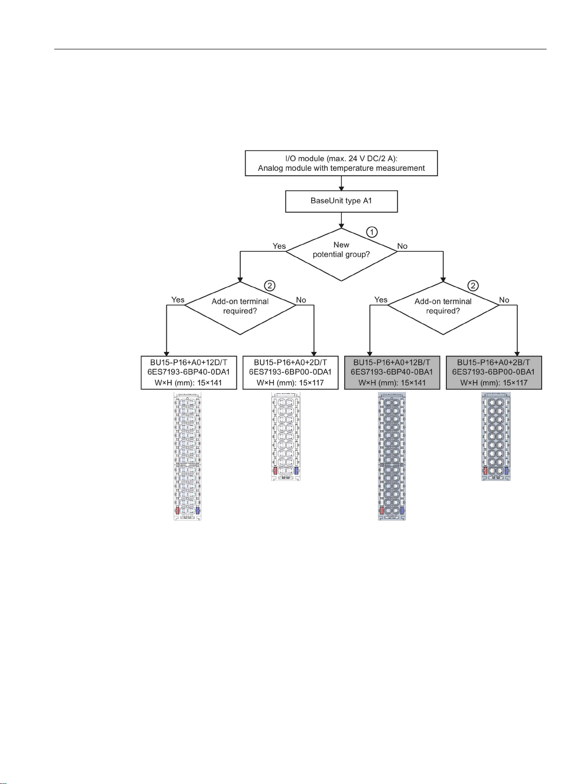
Application planning
3.1.2
Analog modules with temperature measurement
Selection of a suitable BaseUnit
①
module on the left.
②
Example: Sensor supply for AI 4×U/I 2-wire ST
3.1 Selecting the BaseUnit for I/O modules
Light-colored BaseUnit: Configuration of a new potential group, electrical isolation from adja-
cent module on the left. The first BaseUnit of the ET 200SP is usually a light -colored BaseUnit
for feeding the supply voltage L+.
Dark-coloredBaseUnit: Continuation of the internal power and AUX buses from the adjacent
Additional terminals: 2×5 internally bridged terminals for individual use up to 24 V DC/2 A
Figure 3-2 Analog modules with temperature measurement
Distributed I/O system
System Manual, 12/2016, A5E03576849-AG
37
Page 38
Application planning
3.2
Selecting motor starters with a suitable BaseUnit
3.2.1
Selecting a BaseUnit for motor starters
Voltage range
Selection criteria for the BaseUnit
3.2 Selecting motor starters with a suitable BaseUnit
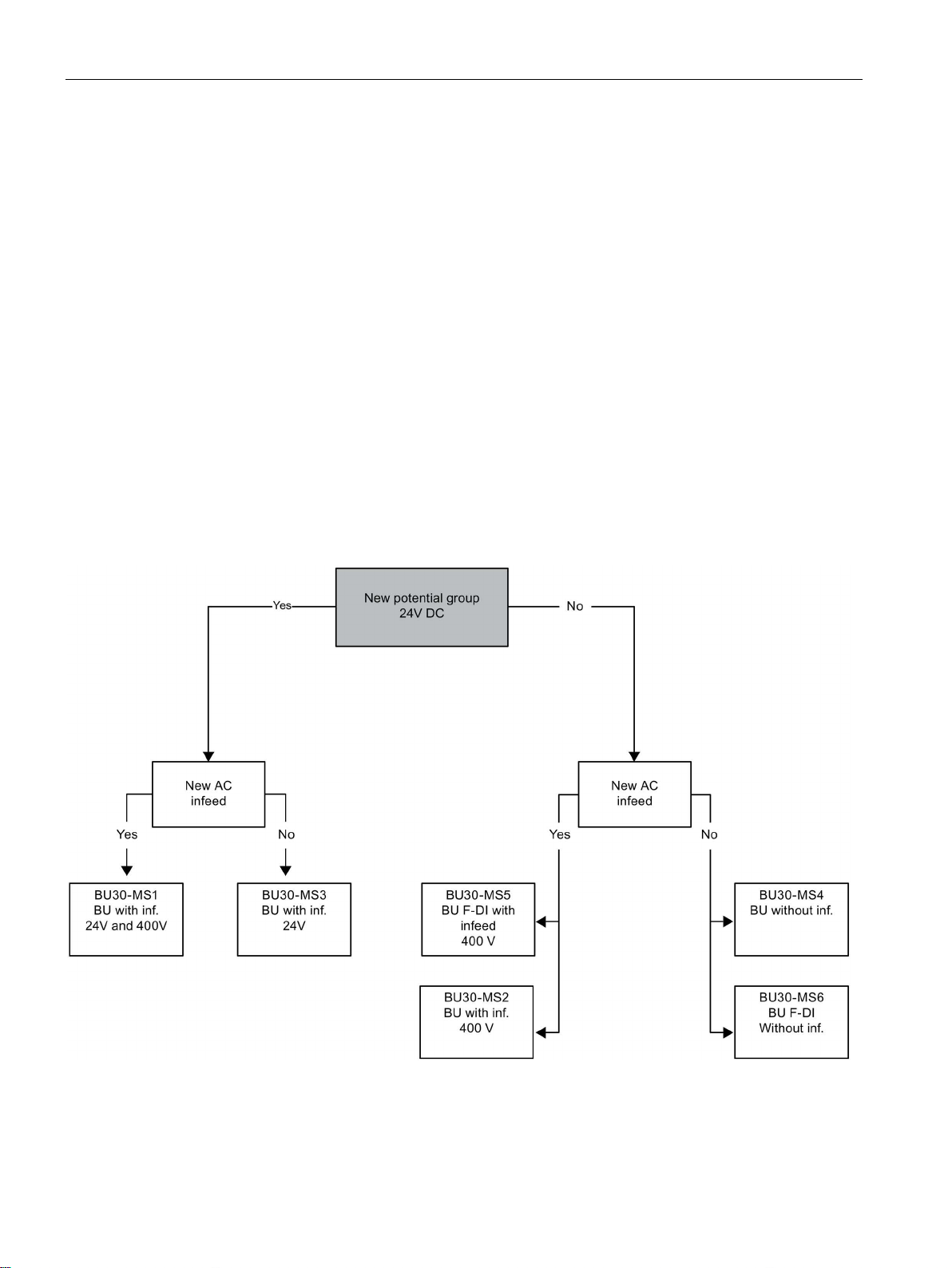
The motor starter BaseUnits "BU30-MS1", "BU30-MS2", "BU30-MS3" and "BU30-MS4" are
compatible with all non-fail-safe motor starters. The motor starter BaseUnits "BU30-MS1",
"BU30-MS2", "BU30-MS3", "BU30-MS4", "BU30-MS5" and "BU30-MS6" are compatible with
all fail-safe motor starters. You will find an overview of available BaseUnits for motor starters
here (Page 32). With the different BaseUnits, you can form different potential groups for the
24 V DC electronics supply (L+/M) and for the AC infeed.
The voltage range of the AC infeed is between 48 V AC and 500 V AC.
The figure below shows the criteria you use to select the appropriate BaseUnit:
Form separate potential groups on the infeed bus for single-phase (L, N, PE) and threephase (L1, L2, L3, PE) operation.
Distributed I/O system
38 System Manual, 12/2016, A5E03576849-AG
Page 39
Application planning
3.2.2
Selecting the motor starter
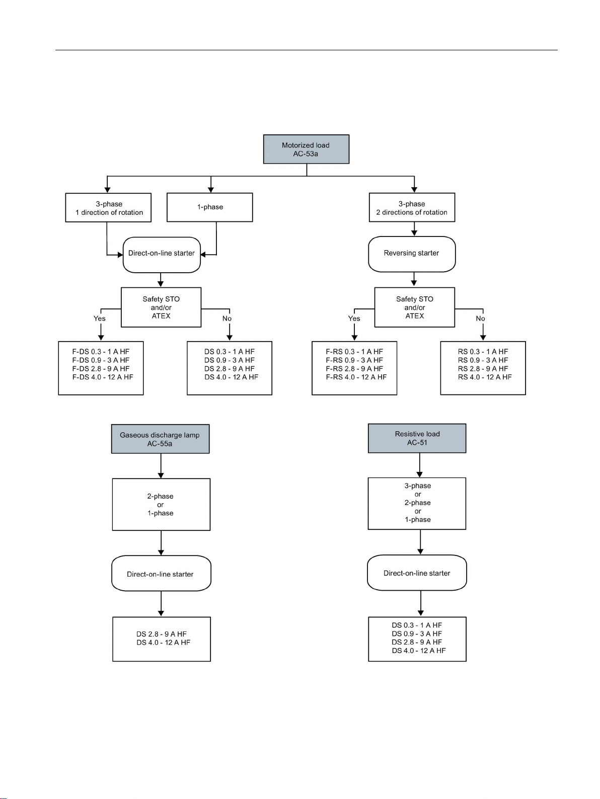
3.2 Selecting motor starters with a suitable BaseUnit
You select the suitable motor starter using the load type according to the following scheme:
Distributed I/O system
System Manual, 12/2016, A5E03576849-AG
39
Page 40
Application planning
3.2.3
Selecting accessories for motor starters
3.2 Selecting motor starters with a suitable BaseUnit
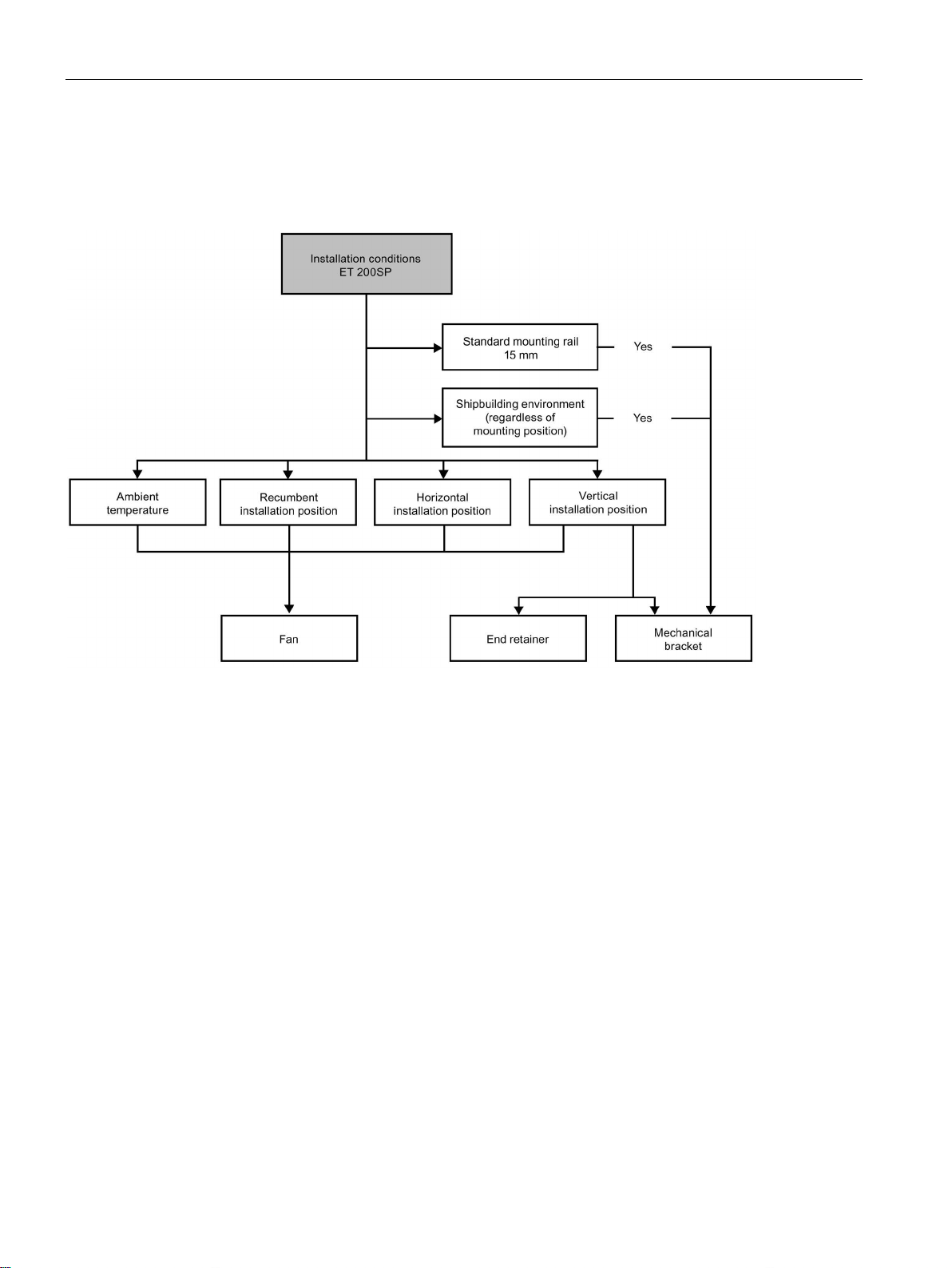
Observe the installation conditions of the station with ET 200SP motor starters. The figure
below shows the criteria the station must meet:
Distributed I/O system
40 System Manual, 12/2016, A5E03576849-AG
Page 41
Application planning
3.3
Hardware configuration
Maximum mechanical configuration
one
Properties
Rule
6/133300) manuals)
duced by 1 module.
Number of motor starters
Maximum of 31 motor starters
ET 200SP
including server module)
Electrical maximum configuration for I/O modules
Maximum electrical configuration for motor starter power bus (24 V DC)
3.3 Hardware configuration
As soon as
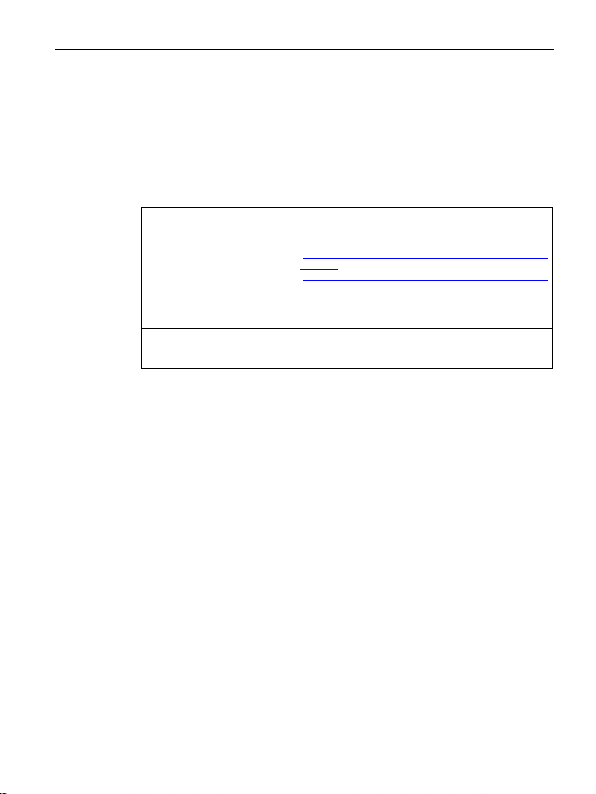
of the following rules applies, the maximum configuration of the ET 200SP
has been reached:
Table 3- 3 Maximum mechanical configuration
Number of modules Maximum of 12/30/32/64 I/O modules (depending on the CPU
Backplane bus length of the
The number of operable I/O modules of a potential group is limited by the following factors:
● Power consumption of the I/O modules
used/the interface module used; see CPU
(http://support.automation.siemens.com/WW/view/en/9046643
9/133300) and interface module
(http://support.automation.siemens.com/WW/view/en/5568331
For every 6 F-modules F-RQ 1x24VDC/24..230VAC/5A
(6ES7136-6RA00-0BF0), the maximum configuration is re-
maximum 1 m mounting width (without CPU/interface module,
● Power consumption of the components supplied via these I/O modules
The maximum current carrying capacity of the terminals on the BaseUnit L+/M is 10 A.
Current carrying capacity refers to the current load via the power bus and the infeed bus of
the ET 200SP station. Consider the current carrying capacity when using a motor starter.
To determine the current requirement of an individual motor starter via the power bus, take
account of the following parameters:
● Current consumption via DC infeed in the ON state
● Current consumption via DC infeed when switching on (40 ms peak load)
● Increased power consumption through fan operation
● Current requirement via encoder supply of the connected DI module
The maximum current carrying capacity of the 24 V potential group is 7 A across the entire
permissible temperature range.
Distributed I/O system
System Manual, 12/2016, A5E03576849-AG
41
Page 42

Application planning
Maximum electrical configuration for motor starter infeed bus (500 V AC)
Address space
3.3 Hardware configuration
To determine the current requirement of an individual motor starter via the infeed bus,
proceed as follows:
Calculate the current requirement via the main current paths of the individual motor starter.
In doing so, take into account the parameter I
starter). The permissible overload characteristics of the motor feeder for motors are
determined with the thermal motor model. You calculate the current value (I
infeed bus of the ET 200SP system according to the following formula:
(set rated operational current of the motor
e
infeed bus
) for the
I
infeed bus
= ∑n(Ie * 1.125)
n = number of motor starters of a potential group on the infeed bus
Refer to the Manual (https://support.industry.siemens.com/cs/ww/en/view/109479973) for
details of how to assign the basic rated operational current Ie parameter.
The following values apply for the potential group of the AC infeed:
● The maximum current carrying capacity is 32 A at an ambient temperature of up to 50 °C.
● The maximum current carrying capacity is 27 A at an ambient temperature of up to 60 °C.
● The maximum current carrying capacity for applications according to UL requirements is
24 A at an ambient temperature of up to 60 °C.
The address space depends on the CPU/interface module (see CPU
(http://support.automation.siemens.com/WW/view/en/90466439/133300) Manual) and the
interface module used (see Interface module
(http://support.automation.siemens.com/WW/view/en/55683316/133300) Manual):
● For PROFINET IO: Dependent on the IO controller/IO device used
● For PROFIBUS DP: Dependent on the DP master used
Distributed I/O system
42 System Manual, 12/2016, A5E03576849-AG
Page 43

Application planning
3.4
Forming potential groups
3.4.1
Basics
Introduction
Requirements
3.4 Forming potential groups
Potential groups for the ET 200SP distributed I/O system are formed by systematically
arranging the BaseUnits.
For formation of potential groups, the ET 200SP distinguishes between the
following BaseUnits:
● BaseUnits BU...D (recognizable by the light-colored terminal box and the light-colored
mounting rail release button):
– Opening of a new potential group (power and AUX bus interrupted to the left)
– Infeed of the supply voltage L+ up to an infeed current of 10 A
● BaseUnits BU...B (recognizable by the dark-colored terminal box and the dark-colored
mounting rail release button):
– Conduction of the potential group (power and AUX bus continued)
– Pick up of the supply voltage L+ for external components or loop-through with a
maximum total current of 10 A
● BaseUnits BU30-MSx (BaseUnit for the motor starter only)
Depending on the version, the BaseUnits in the "BU30-MSx" model series possess the
following properties:
– Opening a new potential group or continuing an existing one
– Feeding in the supply voltage L+ up to an infeed current of 7 A DC
– Opening a new load group or continuing an existing one by means of 500 V AC infeed
bus
– Feeding in the line voltage up to an infeed current of 32 A AC
Distributed I/O system
System Manual, 12/2016, A5E03576849-AG
43
Page 44
Application planning
Placement and grouping of I/O modules
Placement and grouping of I/O modules and motor starters
WARNING
Hazardous Voltage
Can Cause Death, Serious Injury, or Property Damage.
3.4 Forming potential groups
Each BaseUnit BU...D that you install in the ET 200SP configuration opens a new potential
group and supplies all subsequent I/O modules (on BaseUnits BU...B) with the necessary
supply voltage. The first 24 V DC I/O module to the right of the CPU/interface module must
be installed on a light-colored BaseUnit BU...D. Exception: If you insert an AC I/O module or
an AI Energy Meter as the first I/O module, the first BaseUnit in the ET 200SP configuration
can be a dark-colored BaseUnit. The requirement is that you use a CPU or IM 155-6 (as of
V3.0).
If you want to place another BaseUnit BU...B after a BaseUnit BU...D, disconnect the power
and AUX buses and open a new potential group at the same time. This allows individual
grouping of the supply voltages.
Do not connect any BaseUnit of the "BU...B" type on the right of a motor starter's BaseUnit
(BU30-MSxx).
For the potential group (L+/M), the following slot rules apply within the motor starter modules
and other I/O modules of the ET 200SP:
● An unassembled BaseUnit (BaseUnit with BU cover) must be inserted between the CPU,
an interface module or an I/O module and the motor starter. This is not necessary
between the motor starters.
● The empty slot can take on the potential (24 V DC) of the potential group on the left of it
(L+, M), i.e. I/O modules and motor starters can be operated in the same potential group.
● If you would like to insert an I/O module on the right of a motor starter, then use only one
BaseUnit of the BU...D Typ A0 type (light terminal box).
● The BaseUnits BU30-MS2, BU30-MS4, BU30-MS5 and BU30-MS6 can take on the
potential groups of other BaseUnit types.
However, pay attention to the following exceptions:
– Only a BaseUnit of type BU30-MS1 or BU30-MS3 may follow an AS-i module
(AS-i potential group).
– Only BaseUnits with fail-safe motor starters can be connected together in the same
potential group of an F-PM-E.
Hazardous electrical voltage can cause electric shock, burns and property damage.
Disconnect your system and devices from the power supply before starting any assembly
tasks.
Distributed I/O system
44 System Manual, 12/2016, A5E03576849-AG
Page 45

Application planning
AUX bus (AUX(iliary) bus)
A10
NOTICE
AUX bus as PE bar
Self-assembling voltage buses
3.4 Forming potential groups
BaseUnits with additional AUX terminals (e.g. BU15-P16+
+2D) enable the additional
connection of a potential (up to the maximum supply voltage of the module), which is applied
via the AUX bus.
In the case of BaseUnits of motor starters, the AUX bus is interrupted to the left. An internal
24 V DC signal is output to the right.
The AUX bus can be used individually:
● As a protective conductor bar (the requirements of EN 60998-1 apply). To comply with
this standard, a maximum of 8 I/O modules may be plugged into the corresponding
potential group.
● For additionally required voltage
If you use an AUX bus as a protective conductor bar, attach the yellow-green color
identification labels to the AUX terminals, and establish a functional connection to the
central protective conductor connection.
If you stop using the AUX bus as a protective conductor bar, make sure you remove the
yellow-green color identification labels and remove the connection to the central protective
conductor connection again.
The AUX bus is designed as follows:
● Maximum current carrying capacity (at 60 °C ambient air temperature): 10 A
● Permissible voltage: Depending on the BaseUnit type (see BaseUnit manual
(http://support.automation.siemens.com/WW/view/en/59753521))
You must feed in the supply voltage L+ via the BaseUnit BU...D, BU30-MS1 or BU30-MS3 .
Each BaseUnit BU...B allows access to the supply voltage L+ via terminals (red/blue). The
motor starter BaseUnits "BU30-MS1", "BU30-MS2", "BU30-MS3", "BU30-MS4", "BU30-MS5"
and "BU30-MS6" do not have this access.
Distributed I/O system
System Manual, 12/2016, A5E03576849-AG
45
Page 46
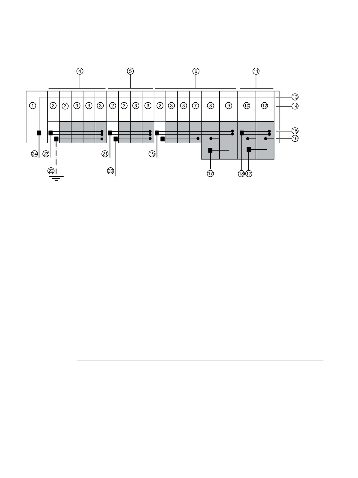
Application planning
Operating principle
1
CPU/interface module
14
Server module
2
BaseUnit BU...D
15
Self-assembling voltage buses P1/P2
3
BaseUnit BU...B
16
AUX bus
4
Potential group 1
17
Infeed bus 500 V AC (L1, L2(N), L3, PE)
5
Potential group 2
18
Supply voltage L+
6
Potential group 3
19
Supply voltage L+ (3)
7
BaseUnit BU...B with dummy module
20
Additionally required voltage
8
BaseUnit BU30-MS2
21
Supply voltage L+ (2)
9
BaseUnit BU30-MS4
22
Protective conductor
10
BaseUnit BU30-MS1
23
Supply voltage L+ (1)
11
Potential group 4
24
Supply voltage 1L+
12
BaseUnit BU30-MS4
13
Backplane bus
Connecting different potentials to the AUX bus
Note
If you apply differen
need to separate the potential groups with a BaseUnit BU...D.
3.4 Forming potential groups
Figure 3-3 Placing the BaseUnits
t potentials to the power or AUX bus within an ET 200SP station, you
Distributed I/O system
46 System Manual, 12/2016, A5E03576849-AG
Page 47

Application planning
3.4.2
Forming potential groups with AC I/O modules
Introduction
Requirements
3.4 Forming potential groups
The AC I/O modules of the ET 200SP are required to connect sensors/actuators with
alternating voltage 24 to 230 V AC.
BaseUnits BU20-P12+A0+4B (BU type B1) and
● DI 4x120..230VAC ST digital input module
● DQ 4x24..230VAC/2A ST digital output module
Distributed I/O system
System Manual, 12/2016, A5E03576849-AG
47
Page 48
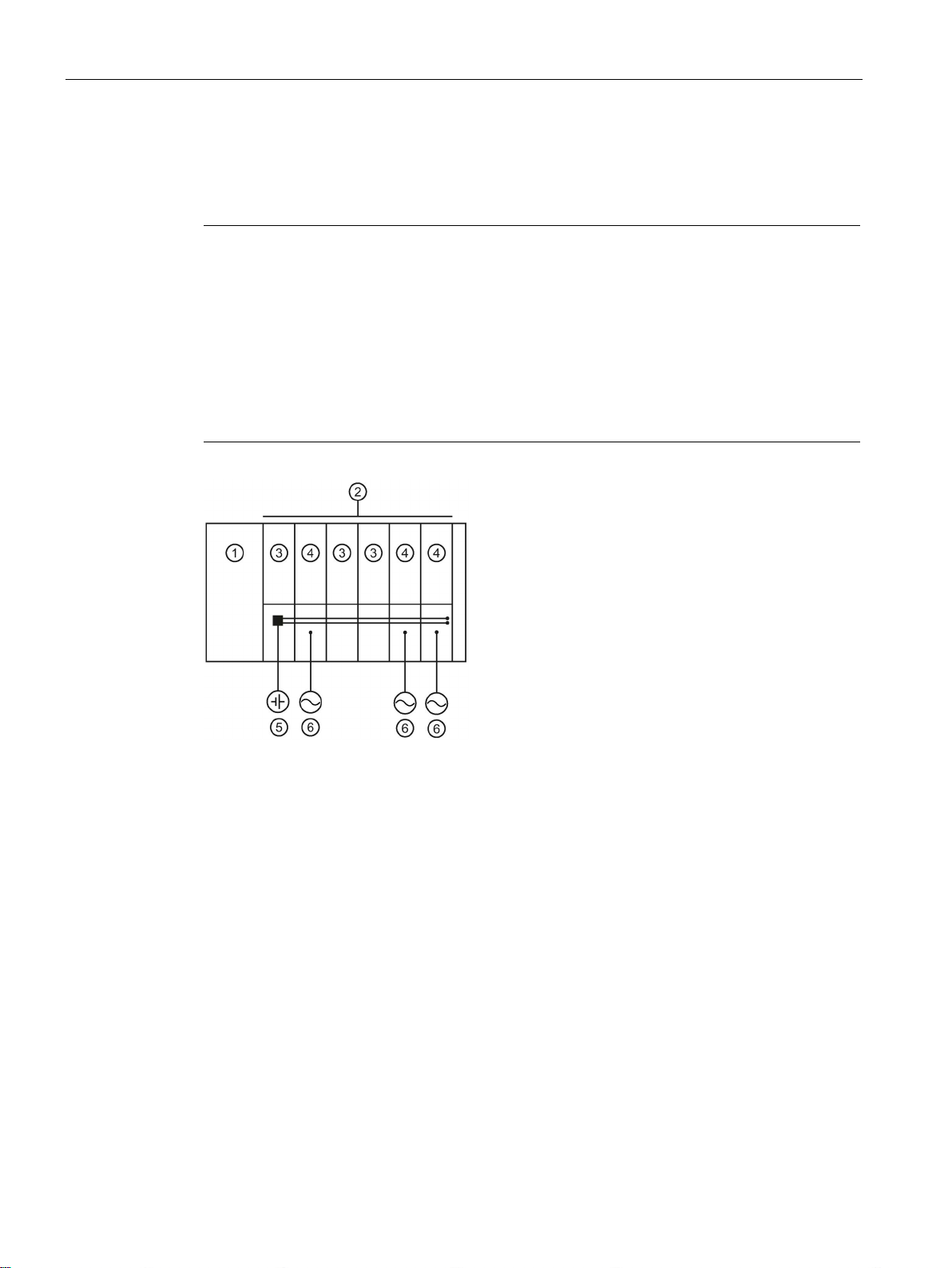
Application planning
Operating principle
Note
Placing the BaseUnits for AC I/O modules
If you insert an AC I/O module as the first I/O module, a BaseUnit BU20
the first BaseUnit to the right of the CPU/interface module in the ET 200S
The requirement is that you use a CPU as of V3.0 or IM 155
•
•
①
CPU/interface module
②
24 V DC potential group
③
BaseUnits with DC I/O modules
④
BaseUnits BU 20-P12+A0+4B with AC I/O modules
⑤
Direct voltage
⑥
Alternating voltage
3.4 Forming potential groups
Connect the required alternating voltage for the AC I/O modules directly at the BaseUnits
BU20-P12+A0+4B (terminals 1L, 2L/1N, 2N). Insert the AC I/O modules on the BaseUnits.
-P12+A0+4B can be
P configuration.
-6 (as of V3.0).
The BaseUnits BU20-P12+A0+4B do not monitor the connected alternating voltage.
Please note the information on limiting the overvoltage and power rating in the AC I/O
module manuals.
Remember to take the BaseUnit type into account during configuration.
Figure 3-4 Placing the BaseUnits for the AC I/O modules
Distributed I/O system
48 System Manual, 12/2016, A5E03576849-AG
Page 49
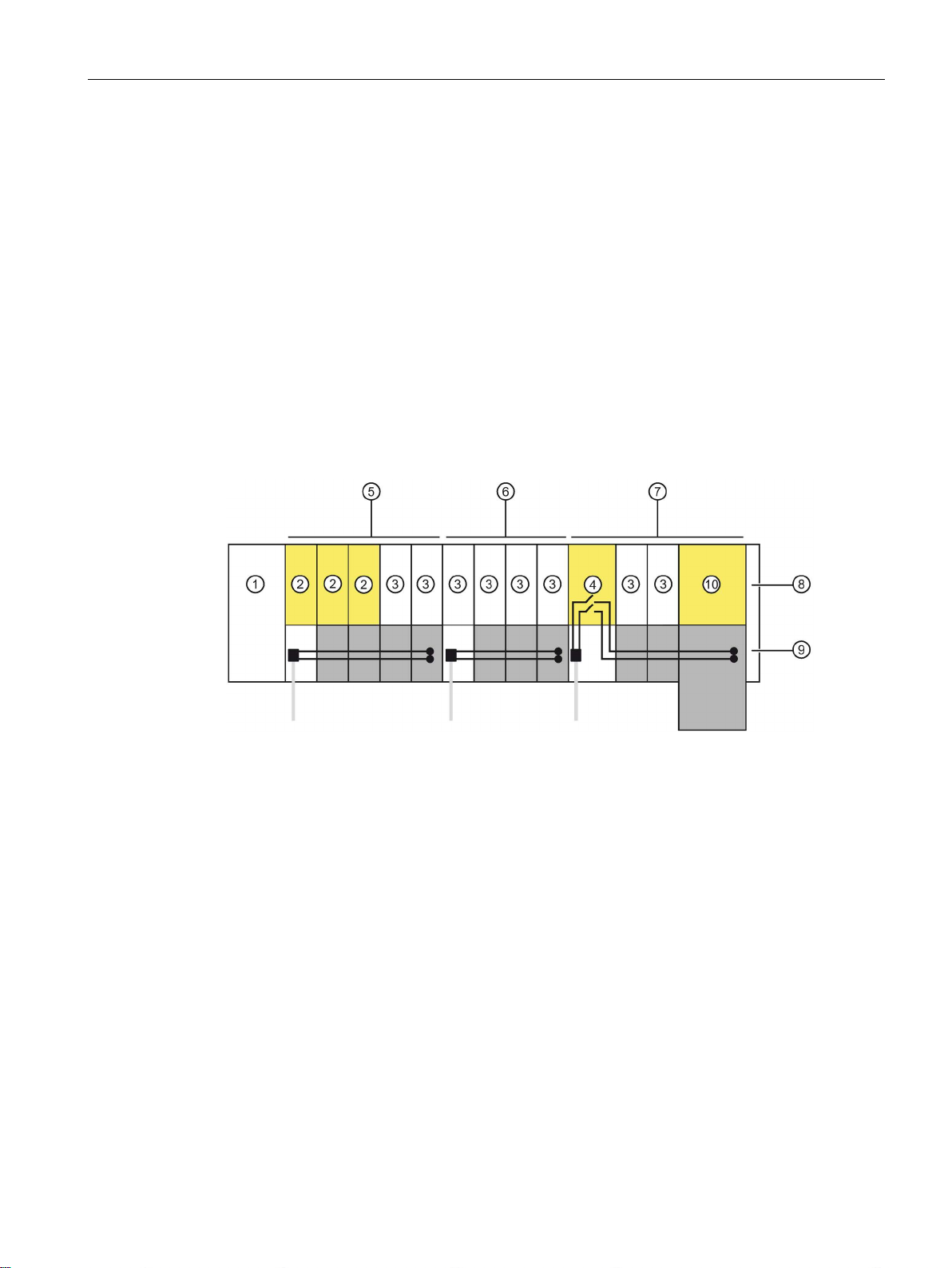
Application planning
3.4.3
Forming potential groups with fail-safe modules
Introduction
Example of an ET 200SP configuration with fail-safe and non-fail-safe modules
①
IM 155-6 PN HF interface module
②
F-module
③
Non-fail-safe module
④
Power module F-PM-E 24VDC/8A PPM ST
⑤
with the non-fail-safe motor starter.
⑥
Non-fail-safe potential group with BaseUnits BU15..D and BU15..B
⑦
ules, up to SIL2/Cat. 3/PLe is possible.
⑧
Server module
⑨
Self-assembling voltage buses P1/P2
⑩
Fail-safe motor starter F-DS HF
3.4 Forming potential groups
ET 200SP distributed I/O systems can be configured using fail-safe and non-fail-safe
modules. This chapter provides an example of a mixed configuration comprising fail-safe and
non-fail-safe modules.
In principle, it is not necessary to operate fail-safe and non-fail-safe modules in separate
potential groups. You can divide the modules into fail-safe and non-fail-safe potential groups
and install them.
The figure below shows an example of a configuration with fail-safe and non-fail-safe
modules within a single ET 200SP distributed I/O system.
Mixed fail-safe and non-fail-safe potential group with BaseUnits BU15..D and BU15..B.
You achieve SIL3/Cat. 4/PLe for the fail-safe modules. No safety category can be achieved
Fail-safe potential group with BaseUnits BU20..D, BU15..B and BU30-MSx.
Through disconnection of the self-assembling voltage bus, and thus of the non-fail-safe mod-
Figure 3-5 ET 200SP - example of a configuration with fail-safe modules
Distributed I/O system
System Manual, 12/2016, A5E03576849-AG
49
Page 50
Application planning
3.4.4
Forming potential groups with motor starters
Properties of the 500 V AC infeed bus
Properties of the self-assembling voltage bus (L+)
WARNING
Electric shock when operating the infeed bus without touch protection cover
WARNING
Electric shock when operating a BaseUnit without an inserted motor starter
3.4 Forming potential groups
The infeed bus has the following properties:
● The infeed bus is assembled by lining up the motor starter BaseUnits "BU30-MSx".
● The infeed bus distributes the energy to the SIMATIC ET 200SP motor starter within one
load group.
● You can open load groups by inserting a 500 V infeed BaseUnit (BU30-MS1, BU30-MS2
or BU30-MS5). With the BaseUnits BU30-MS3, BU30-MS4 or BU30-MS6, you can take
over the infeed bus from the left-hand BaseUnit.
● Via the infeed bus, you have the option of supplying three-phase load groups via L1, L2
and L3 or with single-phase load groups via L and N.
● The permissible voltage range is between 48 and 500 V AC.
● The maximum current carrying capacity is up 32 A (3-phase) at 50 °C and 500 V. Pay
attention to the derating values depending on the configuration.
Self-assembling voltage buses have the following properties:
● Maximum current: 7 A
● Rated voltage: 24 V
Pay attention to the derating values depending on the configuration.
The AUX1 bus is not supported in the BaseUnits of the SIMATIC ET 200SP motor starters.
There is a risk of electric shock when touching the infeed bus if you have not fitted a touch
protection cover on the infeed bus on the right.
Always fit a touch protection cover on the infeed bus on the right (article number: 3RK19081DA00-2BP0).
If you fit a BaseUnit for motor starters without cover (e.g. option handling), there is a risk of
an electric shock when touching the BaseUnit.
Always fit a cover on the BaseUnit (article number: 3RK1908-1CA00-0BP0).
Distributed I/O system
50 System Manual, 12/2016, A5E03576849-AG
Page 51

Application planning
Requirements
Operating principle
Note
The motor starters' AC power supply is not connected to the AC power su
modules (see Chapter "
3.4 Forming potential groups
Use the following devices to form potential groups with motor starters:
● BaseUnits BU30-MSx
● 3RK1308-0xx00-0CP0 motor starters
Feed in the supply voltage L+ via the BaseUnit BU30-MS1 and BU30-MS3 at the 24V DC
and M terminals.
You can operate the motor starter on a single-phase (L1, N, PE) or a three-phase (L1, L2,
L3, PE) AC voltage system. You connect the required AC voltage directly to the BaseUnits
BU30-MSx (terminals L1, L2(N), L3, PE). You plug the motor starter onto the BaseUnits.
pply for the AC I/O
Forming potential groups with AC I/O modules (Page 47)").
Distributed I/O system
System Manual, 12/2016, A5E03576849-AG
51
Page 52
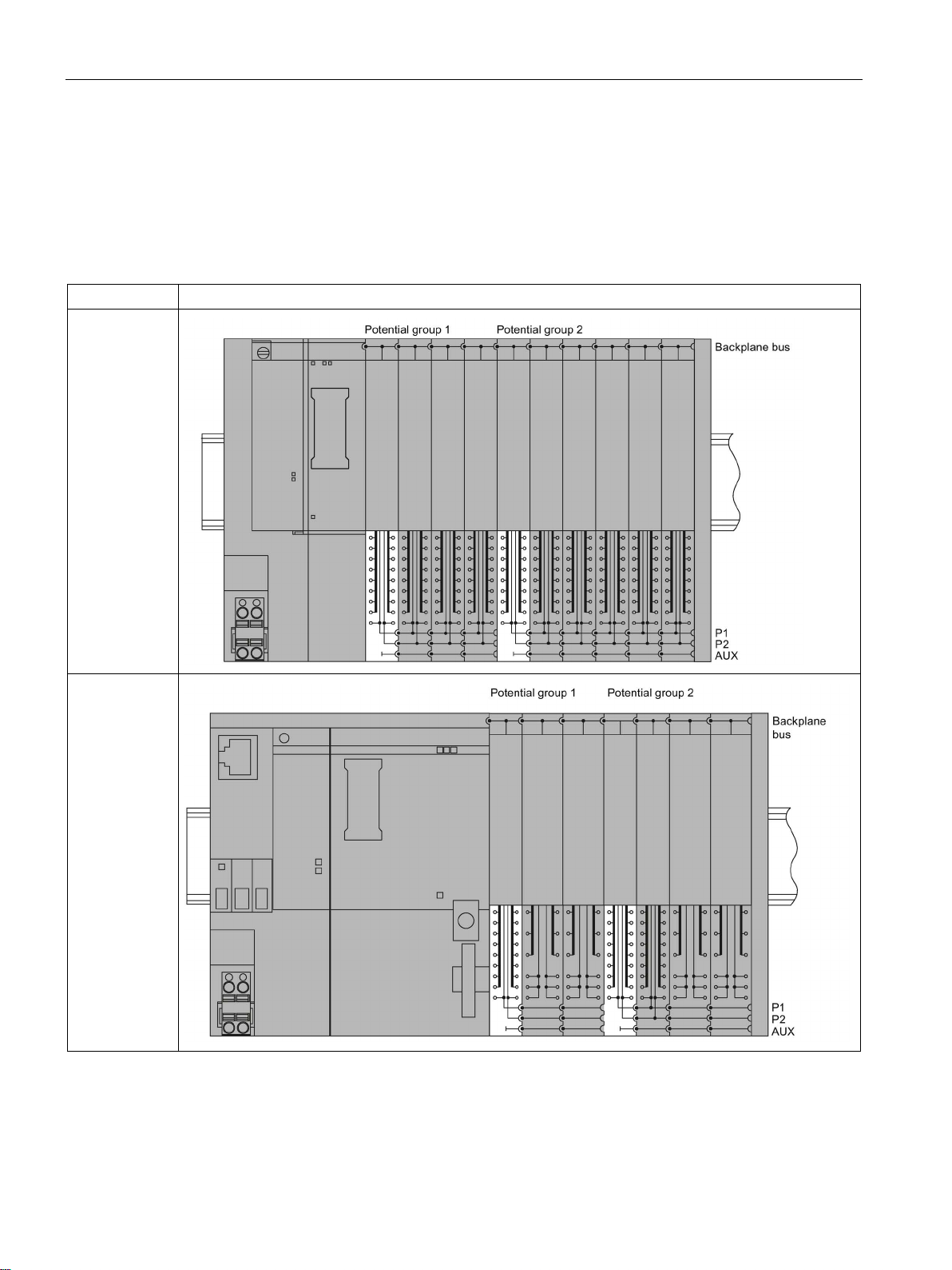
Application planning
3.5
Configuration examples for potential groups
Configuration examples with BaseUnits
BaseUnits
Configuration
3.5 Configuration examples for potential groups
Table 3- 4 Configuration examples with BaseUnits
BU15P16+A0+2D
BU15P16+A0+2B
BU15P16+A0+2D
BU15P16+A0+2B
BU20P12+A0+0B
Distributed I/O system
52 System Manual, 12/2016, A5E03576849-AG
Page 53
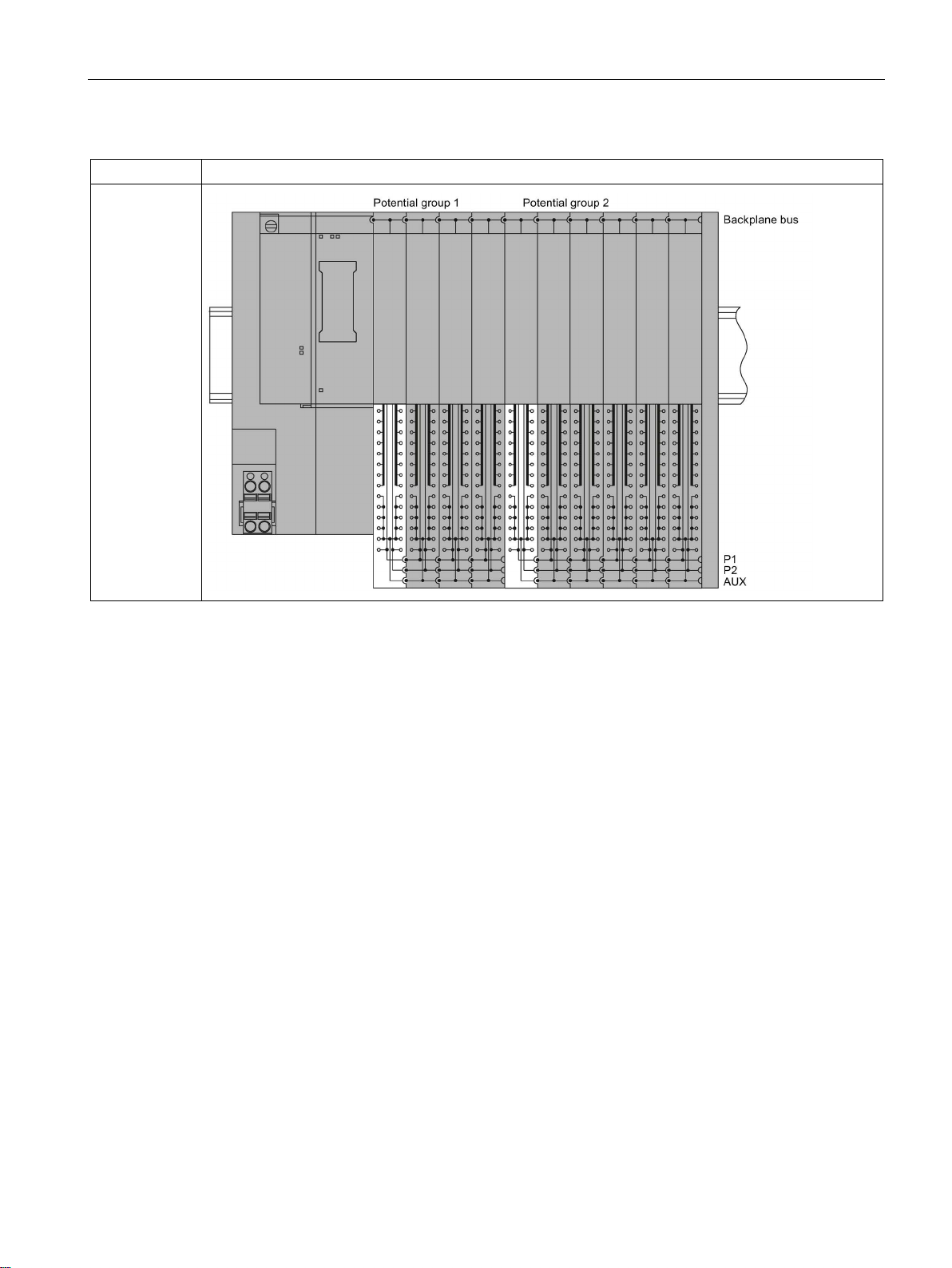
Application planning
BaseUnits
Configuration
3.5 Configuration examples for potential groups
BU15P16+A10+2D
BU15P16+A10+2B
Distributed I/O system
System Manual, 12/2016, A5E03576849-AG
53
Page 54

4
4.1
Basics
Introduction
Installation location
Installation position
All modules of the ET 200SP distributed I/O system are open equipment. This means you
may only set up the distributed I/O system ET 200SP in enclosures, cabinets or electrical
equipment rooms and in a dry environment (IP20 degree of protection). These enclosures,
cabinets or electrical equipment rooms must only be accessible with a key or tool. Access
must only be possible for personnel instructed or authorized to work with such equipment.
Install the ET 200SP distributed I/O system into a suitable housing/control cabinet with
sufficient mechanical strength, fire protection and at least IP54 degree of protection
according to EN 60529, and take into consideration the ambient conditions for operating the
devices.
You can mount the ET 200SP distributed I/O system in any position. The preferred mounting
position is horizontal mounting on a vertical wall. The ambient temperature may be restricted
in certain installation positions. You will find more information in the section Mechanical and
climatic environmental conditions (Page 279).
You can only install motor starters vertically, horizontally or on their backs. Pay attention to
chapter "Installation conditions for motor starters (Page 58)" when using motor starters.
Distributed I/O system
54 System Manual, 12/2016, A5E03576849-AG
Page 55

Installation
Mounting rail
Note
If the ET
the ET
8WA1010
system from shifting to the side.
Note
If the ET
recommend that you screw the mounting rail to the mounting surface at intervals of approx.
200 mm.
Note
If you use mounting rails from other manufact
required properties for your ambient climatic conditions.
4.1 Basics
Mount the ET 200SP distributed I/O system on a mounting rail in accordance with EN 60715
(35 × 7.5 mm or 35 × 15 mm).
You need to ground the mounting rail separately in the control cabinet. Exception: If you
install the rail on grounded, zinc-plated mounting plates, there is no need to ground the rail
separately.
200SP distributed I/O system is exposed to vibration and shock loads, both ends of
200SP system assembly must be mechanically fixed to the mounting rail (e.g using
-1PH01 ground terminals). This measure prevents the ET 200SP distributed I/O
200SP distributed IO system is exposed to increased vibrations and shock, we
The following are suitable surfaces for the mounting rails:
● Steel strip in accordance with Appendix A of EN 60715 or
● Tinned steel strip. We recommend these in conjunction with the mounting rails in the
section Accessories/spare parts (Page 286).
urers, make sure that they have the
Distributed I/O system
System Manual, 12/2016, A5E03576849-AG
55
Page 56
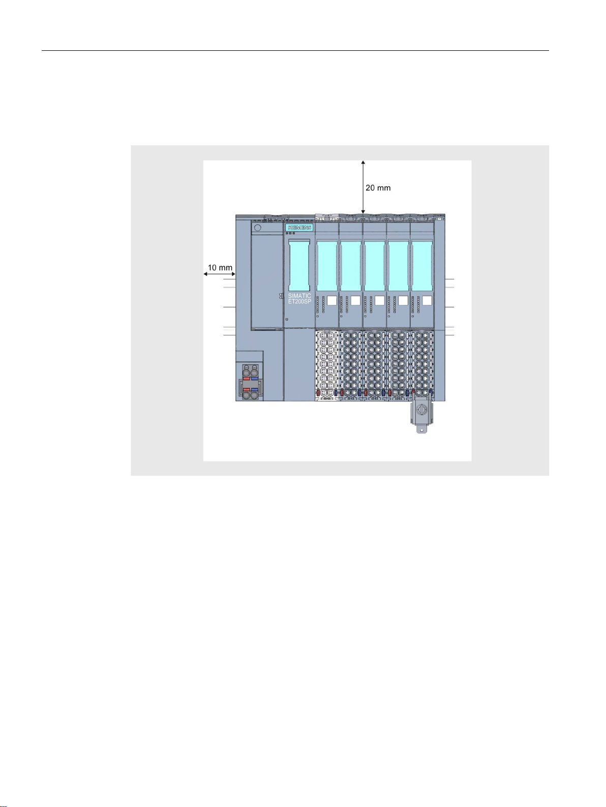
Installation
Minimum clearances
4.1 Basics
The figure below shows the minimum clearances you must observe when installing or
dismantling the ET 200SP distributed I/O system.
Figure 4-1 Minimum clearances
Distributed I/O system
56 System Manual, 12/2016, A5E03576849-AG
Page 57
Installation
General rules for installation
WARNING
Hazardous Voltage
Can Cause Death, Serious Injury, or Property Damage.
Note
Mount the ET
WARNING
Protection from conductive contamination
4.1 Basics
Hazardous electrical voltage can cause electric shock, burns and property damage.
Disconnect your system and devices from the power supply before starting any assembly
tasks.
Observe the following rules:
● Installation starts on the left-hand side with the CPU/interface module.
● A light-colored BaseUnit BU..D0, BU30-MS1 or BU30-MS3 with infeed of the supply
voltage L+ follows the CPU/the interface module or is placed at the start of each potential
group.
If you fit an AC I/O module or an AI Energy Meter as the first I/O module, then the first
BaseUnit in the structure of the distributed I/O system ET 200SP may be a dark-colored
BaseUnit. The requirement is that you use a CPU or IM 155-6 (as of V3.0).
● This is followed by BaseUnits BU..B, BU30-MS2 or BU30-MS4 (with a dark-colored
terminal box).
● The matching I/O modules / motor starters can be plugged onto the BaseUnits. You will
find matching combinations of BaseUnits and I/O modules / motor starters in Application
planning (Page 32).
● The server module completes the configuration of the ET 200SP distributed I/O system.
200SP distributed I/O system only with disconnected supply voltage.
For fail-safe ET 200SP modules:
Taking into account the environmental conditions, the devices must be protected from
conductive contamination.
This can be achieved, for example, by installing the devices in a control cabinet with the
appropriate degree of protection.
Distributed I/O system
System Manual, 12/2016, A5E03576849-AG
57
Page 58

Installation
4.2
Installation conditions for motor starters
Mechanical brackets
Designing interference-free motor starters
4.2 Installation conditions for motor starters
Observe the following installation conditions when using an ET 200SP motor starter:
● Mounting position
You can install the motor starter vertically, horizontally or on its back. The mounting
position refers to the alignment of the mounting rail The maximum permissible ambient
temperature range depends on the mounting position:
– Up to 60° C: Horizontal mounting position
– Up to 50° C: Vertical and recumbent mounting position
Also take into account the current carrying capacity of the ET 200SP components.
In the case of a vertical mounting position, use end retainers "8WA1808" at both ends of
the ET 200SP station:
● Mounting rail
Use one of the following mounting rails:
– 35x15 mm DIN rail in accordance with DIN EN 60715
– 35x7.5 mm DIN rail in accordance with DIN EN 60715
– SIMATIC S7 mounting rail
● Current carrying capacity of the ET 200SP station
Current carrying capacity refers to the current load via the power bus and the infeed bus
of the ET 200SP station.
Depending on the ambient conditions and mounting position, you have to take account of the
fan unit or additional mechanical fixings.
Use the mechanical brackets in the following situations:
● When using a 15 mm mounting rail
● With a vertical mounting position
● For applications according to shipbuilding standards in all mounting positions with 7.5 mm
and 15 mm mounting rails
For interference-free operation of the ET 200SP station in accordance with standard
IEC 60947-4-2, use a dummy module before the first motor starter.
Note the following mounting rules:
Use the following dummy module on the standard mounting rail between the previous
module and the SIMATIC ET 200SP motor starter:
BU cover 15 mm: 6ES7133-6CV15-1AM0 with BaseUnit 6ES7193-6BP00-0BA0
For operation of the ET 200SP station with an unused BaseUnit, a cover must be provided
for the open BaseUnit plug contacts (power connector, power bus connector, and backplane
bus connector).
The cover protects the plug contacts against dirt. The BU cover can be ordered as an
accessory.
Distributed I/O system
58 System Manual, 12/2016, A5E03576849-AG
Page 59
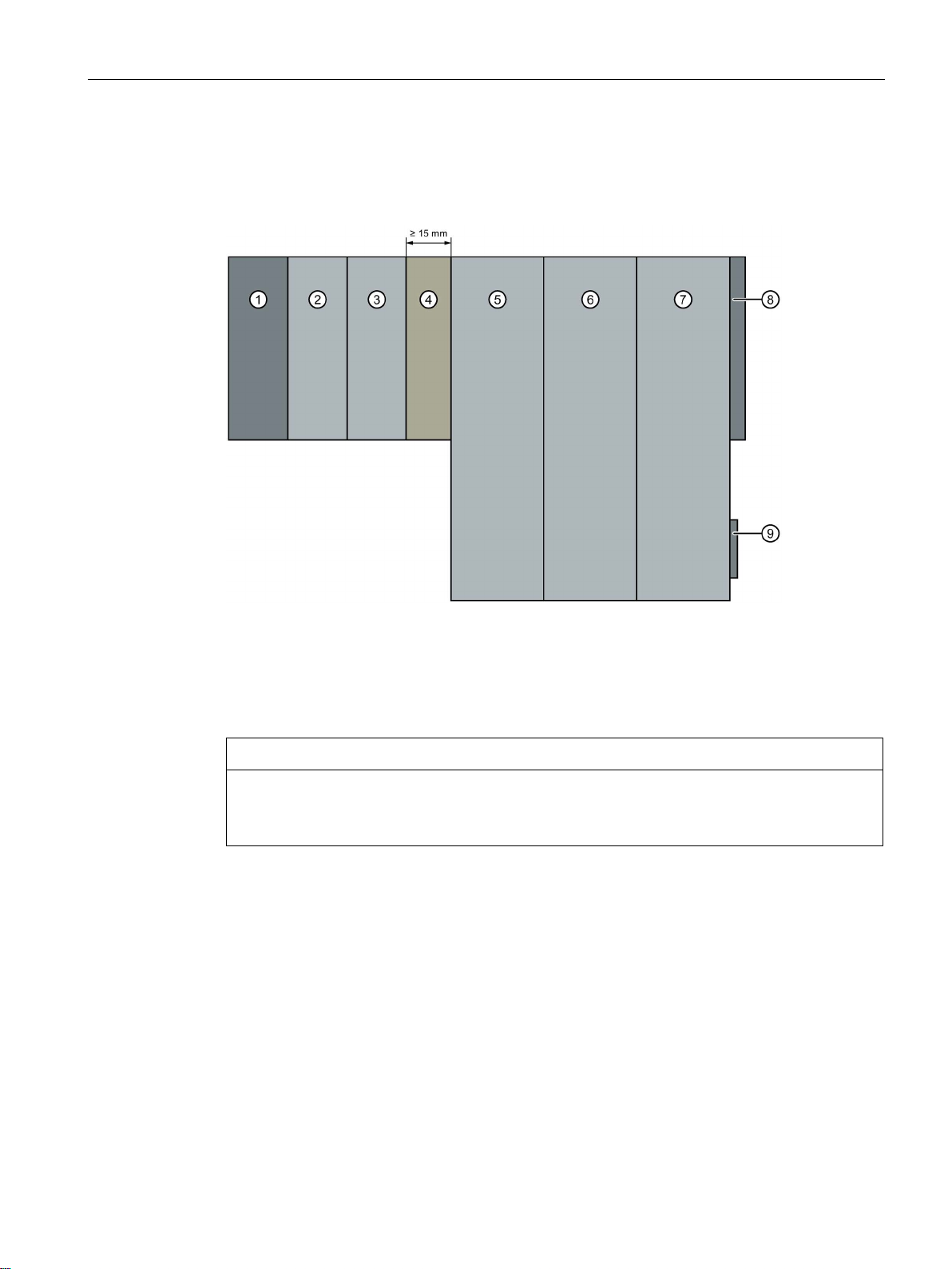
Installation
Mount the dummy module
①
Interface module
⑥
Motor starter
②
Digital input module
⑦
Motor starter
③
Digital output module
⑧
Server module
④
Dummy module
⑨
Infeed bus cover
⑤
Motor starter
NOTICE
Ensure interference immunity
4.2 Installation conditions for motor starters
The figure below provides a schematic representation of how to implement measures for
improving interference immunity.
You must not plug any other module into the BaseUnit of the dummy module, otherwise
interference immunity is no longer ensured.
Distributed I/O system
System Manual, 12/2016, A5E03576849-AG
59
Page 60
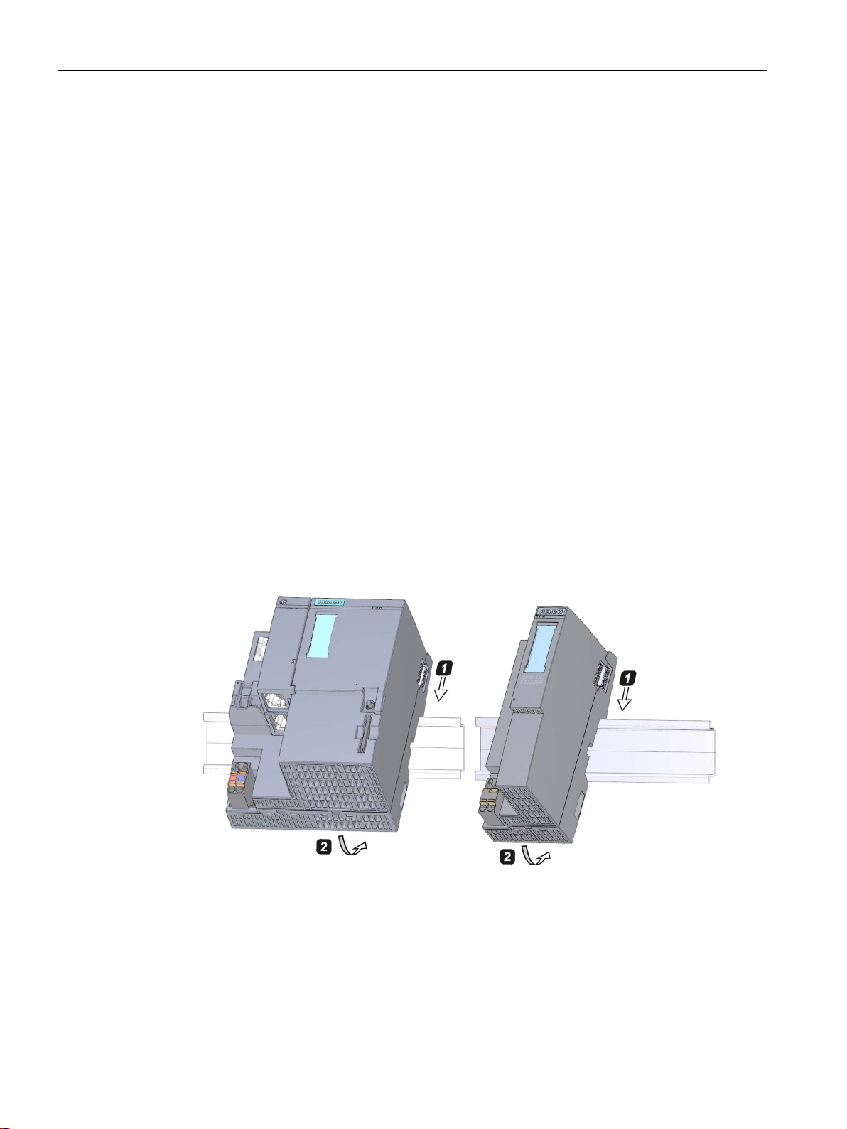
Installation
4.3
Mounting the CPU/interface module
Introduction
Requirement
Required tools
Mounting the CPU/interface module
4.3 Mounting the CPU/interface module
The CPU/the interface module connects the ET 200SP distributed I/O system to the fieldbus
and exchanges the data between the higher-level control system and the I/O modules /
motor starters.
The mounting rail is fitted.
3 to 3.5 mm screwdriver (only for mounting and removing the BusAdapter)
Watch the video sequence (http://support.automation.siemens.com/WW/view/en/95886218)
To install a CPU/interface module, follow these steps:
1. Install the CPU/interface module on the mounting rail.
2. Swivel the CPU/interface module towards the back until you hear the mounting rail
release button click into place.
Figure 4-2 Mounting the CPU/interface module
Distributed I/O system
60 System Manual, 12/2016, A5E03576849-AG
Page 61

Installation
Dismantling the CPU/interface module
Note
It is not necessary to remove the BusAdapter from the CPU/interface module.
4.3 Mounting the CPU/interface module
The CPU/interface module is wired and BaseUnits are located to its right.
To remove the CPU/interface module, follow these steps:
1. Switch off the supply voltage on the CPU/interface module. Remove the 24 V DC
connector from the CPU/interface module.
2. Press the mounting rail release button on the first BaseUnit. At the same time, shift the
CPU/interface module parallel to the left until it detaches from the rest of the module
group.
Note: The mounting rail release button is located above the CPU/interface module or
BaseUnit.
3. While pressing the mounting rail release button on the CPU/interface module, swivel the
CPU/interface module off of the mounting rail.
Distributed I/O system
System Manual, 12/2016, A5E03576849-AG
61
Page 62
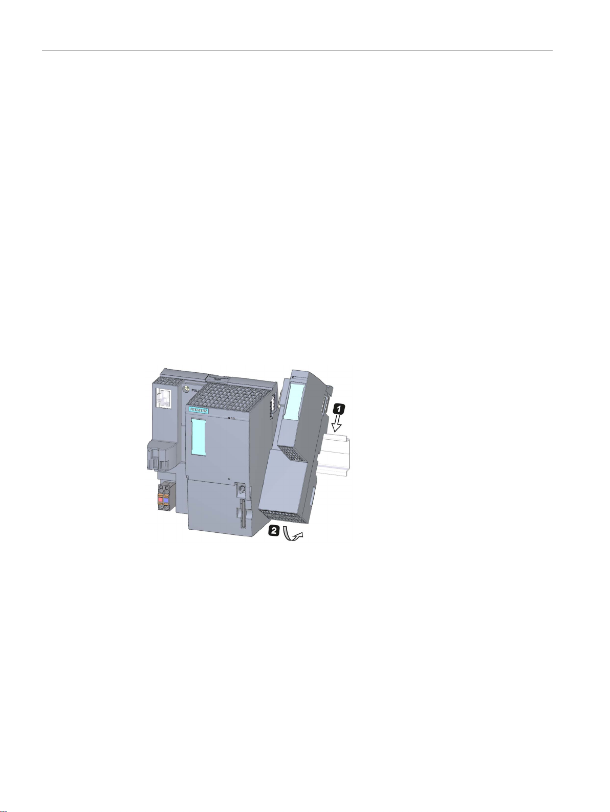
Installation
4.4
Installing the CM DP communication module
Introduction
Requirements
Installing CM DP
4.4 Installing the CM DP communication module
You need the CM DP communication module to use the CPU with a DP master or DP slave.
● The mounting rail is fitted.
● The CPU is installed.
To install the CM DP communication module, follow these steps:
1. Install the CM DP to the right of the CPU.
2. Swivel the CM DP towards the back until you hear the mounting rail release button click
into place.
3. Slide the CM DP to the left until you hear it click into the CPU.
Figure 4-3 Installing CM DP
Distributed I/O system
62 System Manual, 12/2016, A5E03576849-AG
Page 63

Installation
Removing a CM DP
Note
It is not necessary to remove the bus connector from the CM DP unless you have t
the CM DP.
4.4 Installing the CM DP communication module
The CPU and the CM DP are wired and BaseUnits are located to its right.
To remove the CM DP communication module, follow these steps:
1. Switch off the supply voltage on the CPU.
2. Press the mounting rail release button on the first BaseUnit and, at the same time, move
the CPU and the CM DP parallel to the left until they detach from the rest of the module
group (clearance about 16 mm).
3. Press the mounting rail release button on the CM DP and move it to the right until it
detaches from the CPU (clearance about 8 mm).
4. While pressing the mounting rail release button on the CM DP, swivel the CM DP off of
the mounting rail.
o replace
Distributed I/O system
System Manual, 12/2016, A5E03576849-AG
63
Page 64
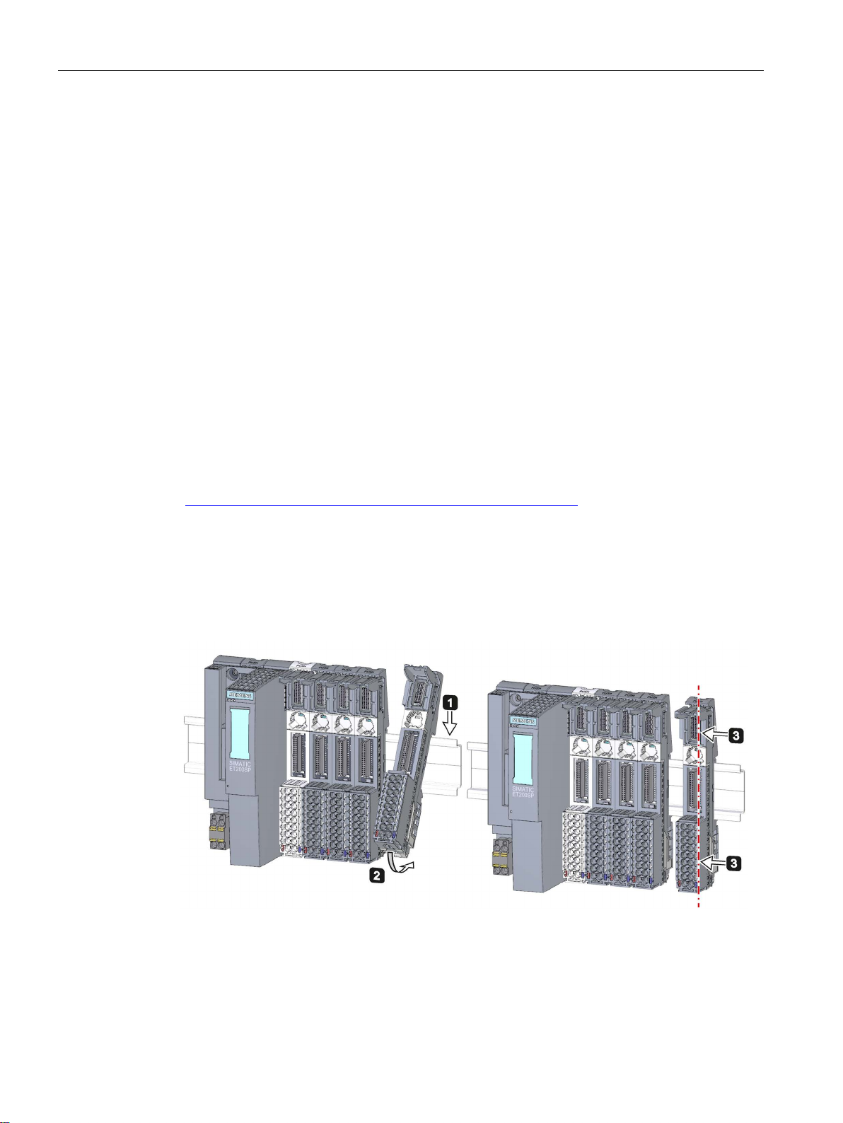
Installation
4.5
Mounting BaseUnits for I/O modules
Introduction
Requirements
Required tools
Installing a BaseUnit
4.5 Mounting BaseUnits for I/O modules
The BaseUnits are used for electromechanical connection between the individual ET 200SP
components. They also provide terminals for connecting external sensors, actuators and
other devices.
The mounting rail is fitted.
3 to 3.5 mm screwdriver (only for dismantling the terminal box and the encoding element)
Watch "Install configuration" video sequence
(http://support.automation.siemens.com/WW/view/en/95886218)
To install a BaseUnit, follow these steps:
1. Install the BaseUnit on the mounting rail.
2. Swivel the BaseUnit backwards until you hear it click into the mounting rail.
3. Slide the BaseUnit parallel to the left until you hear it click into the preceding
CPU/interface module or BaseUnit.
Figure 4-4 Installing a BaseUnit
Distributed I/O system
64 System Manual, 12/2016, A5E03576849-AG
Page 65
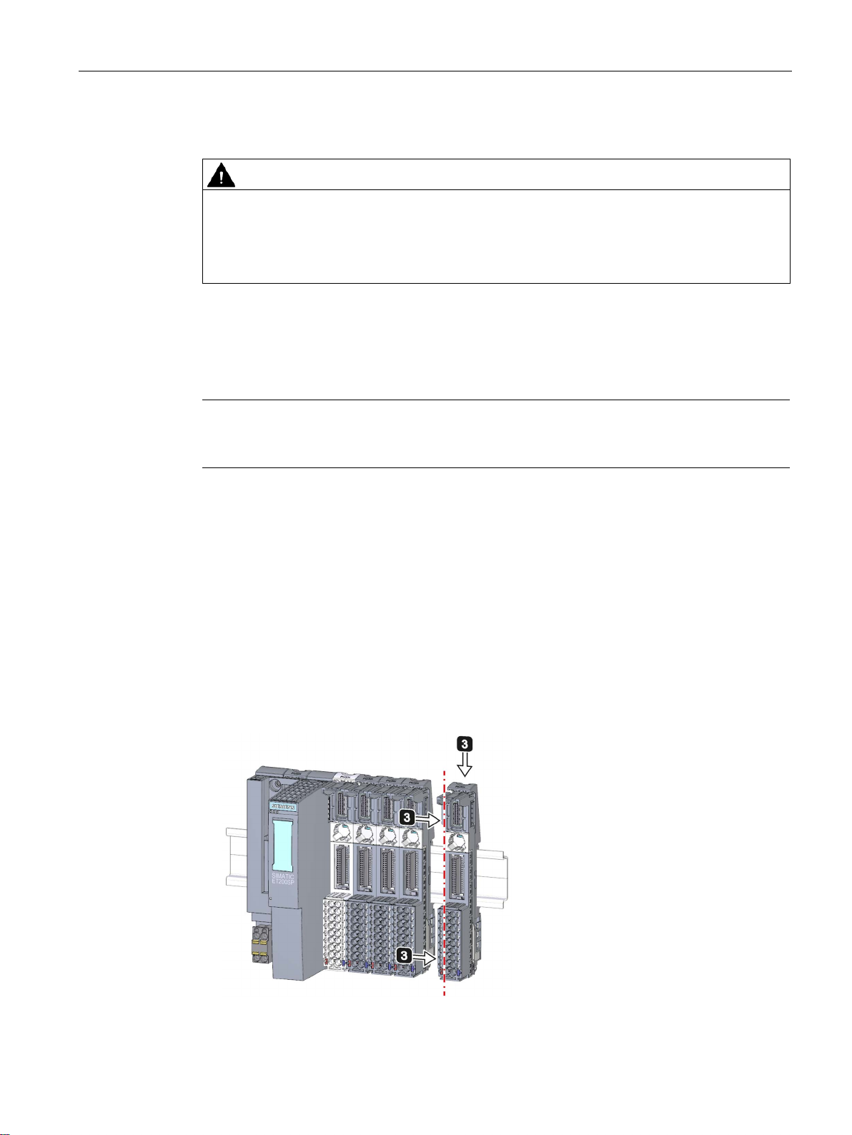
Installation
Removing a BaseUnit
WARNING
Hazardous Voltage
Note
The terminal box can be replaced without removing the BaseUnit. Ref
Replacing
the terminal box on the BaseUnit
Removing (from the right):
Removing (from the left):
4.5 Mounting BaseUnits for I/O modules
Hazardous electrical voltage can cause electric shock, burns and property damage.
Disconnect your system and devices from the power supply before starting any assembly
tasks.
To remove a BaseUnit, follow these steps:
The BaseUnit is wired and there are other BaseUnits to its right and left.
To remove a specific BaseUnit, move the neighboring modules. As soon as you have
created a clearance of about 8 mm from the neighboring BaseUnits, you can remove the
BaseUnit.
er to section
(Page 243).
To remove a BaseUnit, follow these steps:
1. If present, turn off the supply voltage on the BaseUnit.
2. Loosen the wiring on the BaseUnit (with a 3 to 3.5 mm screwdriver).
3.
Press the mounting rail release button on the corresponding BaseUnit. Move the
BaseUnit parallel to the right and swivel the BaseUnit off of the mounting rail while
pressing the mounting rail release button.
Press the mounting rail release button on the corresponding BaseUnit and on the
BaseUnit to the right of this. Move the BaseUnit parallel to the left and swivel it out of the
mounting rail while pressing the mounting rail release button.
Note: The mounting rail release button is located above the BaseUnit.
Figure 4-5 Removing the BaseUnit (removing from the right)
Distributed I/O system
System Manual, 12/2016, A5E03576849-AG
65
Page 66
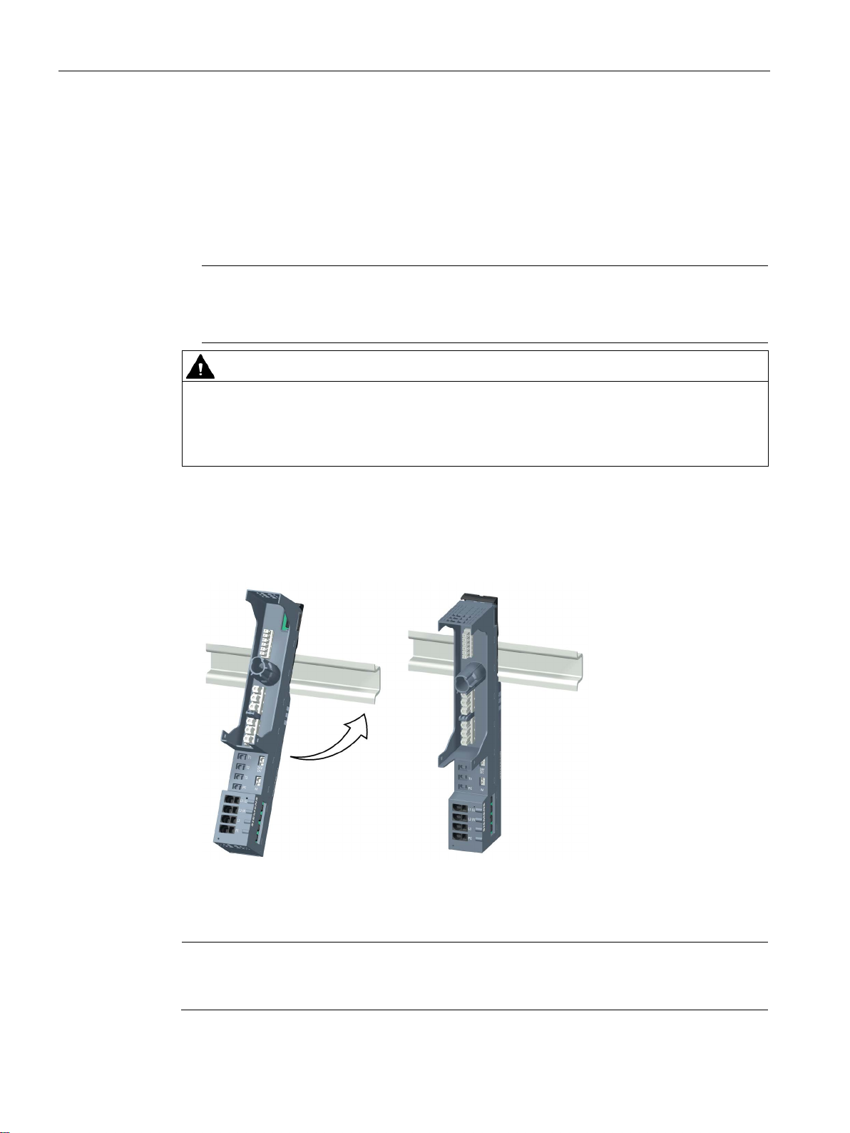
Installation
4.6
Mounting and dismantling BaseUnits for motor starters
Requirements
Note
Mechanical bracket for BaseUnit
You will find out how to mount the mechanical bracket for the BaseUnit in chapter
"
CAUTION
Protection against electrostatic charge
Mounting a BaseUnit
Note
The BaseUnits for motor starters can be plugged together with the BaseUnits for I/
modules.
4.6 Mounting and dismantling BaseUnits for motor starters
● The mounting rail is fitted.
● When using a 15 mm mounting rail, the mechanical bracket (3RK1908-1EA00-1BP0)
must be mounted.
Mounting the mechanical bracket for the BaseUnit (Page 71)".
When handling and installing the SIMATIC ET 200SP motor starter, ensure protection
against electrostatic charging of the components. Changes to the system configuration and
wiring are only permissible after disconnection from the power supply.
Proceed as follows to mount a BaseUnit for motor starters:
1. Hook the BaseUnit into the DIN rail from above.
2. Swing the BaseUnit to the rear until the BaseUnit audibly engages.
3. Slide the individual BaseUnits to the left to the previous BaseUnit until they audibly
engage.
Assemble the BaseUnits only on the DIN rail.
Distributed I/O system
66 System Manual, 12/2016, A5E03576849-AG
O
Page 67
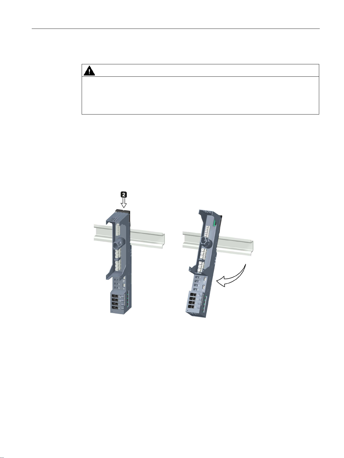
Installation
Disassembling the BaseUnit
WARNING
Hazardous Voltage
4.6 Mounting and dismantling BaseUnits for motor starters
Hazardous electrical voltage can cause electric shock, burns and property damage.
Disconnect your system and devices from the power supply before starting any assembly
tasks.
To disassemble the BaseUnit, proceed as follows:
1. Disconnect the main power supply and the control current supply of the SIMATIC ET
200SP motor starter.
2. Actuate the DIN rail release on the BaseUnit of the motor starter.
3. Move the BaseUnit to the left. As soon as there is a clearance of approximately 8 mm to
the neighboring BaseUnits, you can disassemble the BaseUnit of the motor starter.
4. Swing the BaseUnit away from the DIN rail while pressing the DIN rail release.
Distributed I/O system
System Manual, 12/2016, A5E03576849-AG
67
Page 68

Installation
4.7
Installing the server module
Introduction
Requirement
Installing the server module
Removing the server module
4.7 Installing the server module
The server module on the far right of the assembly/line completes the ET 200SP distributed
I/O system.
The last BaseUnit is mounted.
Watch "Install configuration" video sequence
(http://support.automation.siemens.com/WW/view/en/95886218)
Proceed as follows to install a server module:
1. Install the server module on the mounting rail on the right next to the last BaseUnit.
2. Swivel the server module backwards on the mounting rail.
3. Move the server module parallel to the left until you hear it click into the last preceding
BaseUnit.
Figure 4-6 Installing the server module
Proceed as follows to remove a server module:
1. Press the mounting rail release button on the server module.
2. Move the server module parallel to the right.
3. While pressing the mounting rail release button, swivel the server module off the
mounting rail.
Distributed I/O system
68 System Manual, 12/2016, A5E03576849-AG
Page 69
Installation
4.8
Mounting further accessories for motor starters
4.8.1
Mounting the cover for the 500 V AC infeed bus
Introduction
DANGER
Hazardous Voltage
Can Cause Death, Serious Injury, or Property Damage.
DANGER
Infeed bus - electric shock
WARNING
Personal injury may occur
4.8 Mounting further accessories for motor starters
The 500 V infeed bus connects all SIMATIC ET 200SP motor starters. For finger-safe
termination of the infeed bus, you must use the cover.
Hazardous electrical voltage causes electric shock, burns and property damage.
Disconnect your system and devices from the power supply before starting any assembly
tasks.
You must provide the infeed bus with a touch protection cover on the right (Article No.:
3RK1308-1DA00-2BP0).
Failure to do so will result in the danger of electric shock.
On the last plugged-in BaseUnit of a motor starter, place a cover on the opening of the
contacts of the infeed bus.
Distributed I/O system
System Manual, 12/2016, A5E03576849-AG
69
Page 70
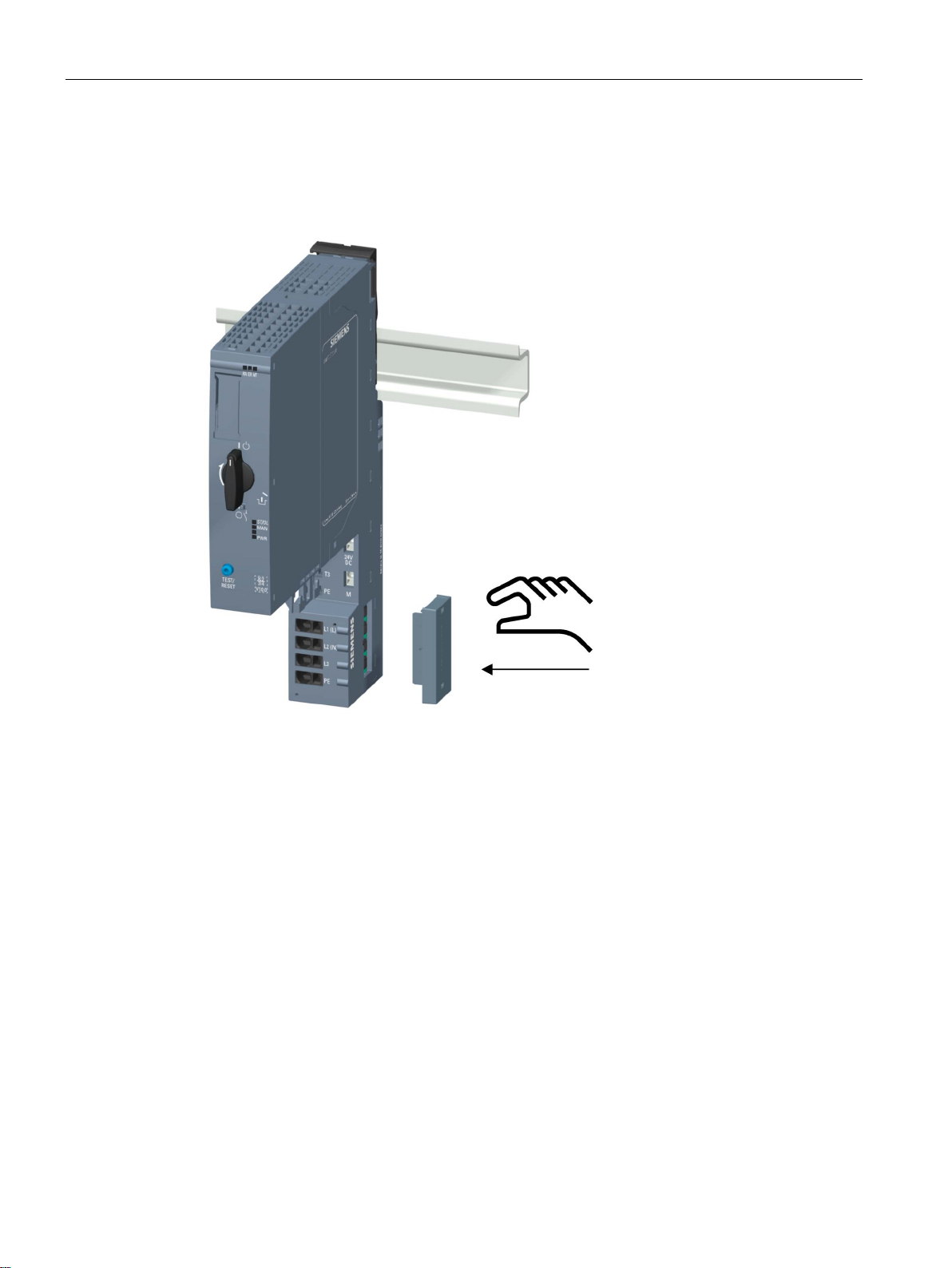
Installation
Procedure
4.8 Mounting further accessories for motor starters
Proceed as follows to mount the infeed bus cover on a SIMATIC ET 200SP motor starter:
1. Press the cover onto the opening of the BaseUnit on the right until it audibly engages.
The cover can be removed again using 2 fingers and without tools.
Distributed I/O system
70 System Manual, 12/2016, A5E03576849-AG
Page 71
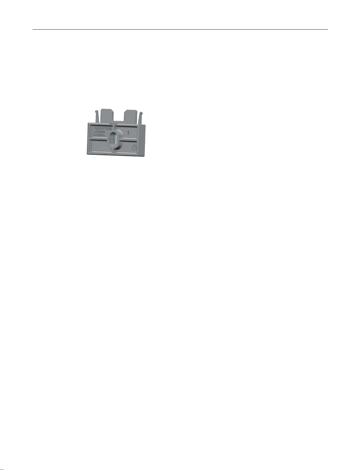
Installation
4.8.2
Mounting the mechanical bracket for the BaseUnit
Introduction
4.8 Mounting further accessories for motor starters
To achieve higher stability, you can use a mechanical bracket on 7.5 mm and 15 mm
mounting rails.
You must use the mechanical bracket in the following situations:
● When using a 15 mm mounting rail
● With a vertical mounting position
● For applications according to shipbuilding standards in all mounting positions with 7.5 mm
and 15 mm mounting rails
You can find further information on the mechanical bracket in chapter "Installation conditions
for motor starters (Page 58)".
Distributed I/O system
System Manual, 12/2016, A5E03576849-AG
71
Page 72
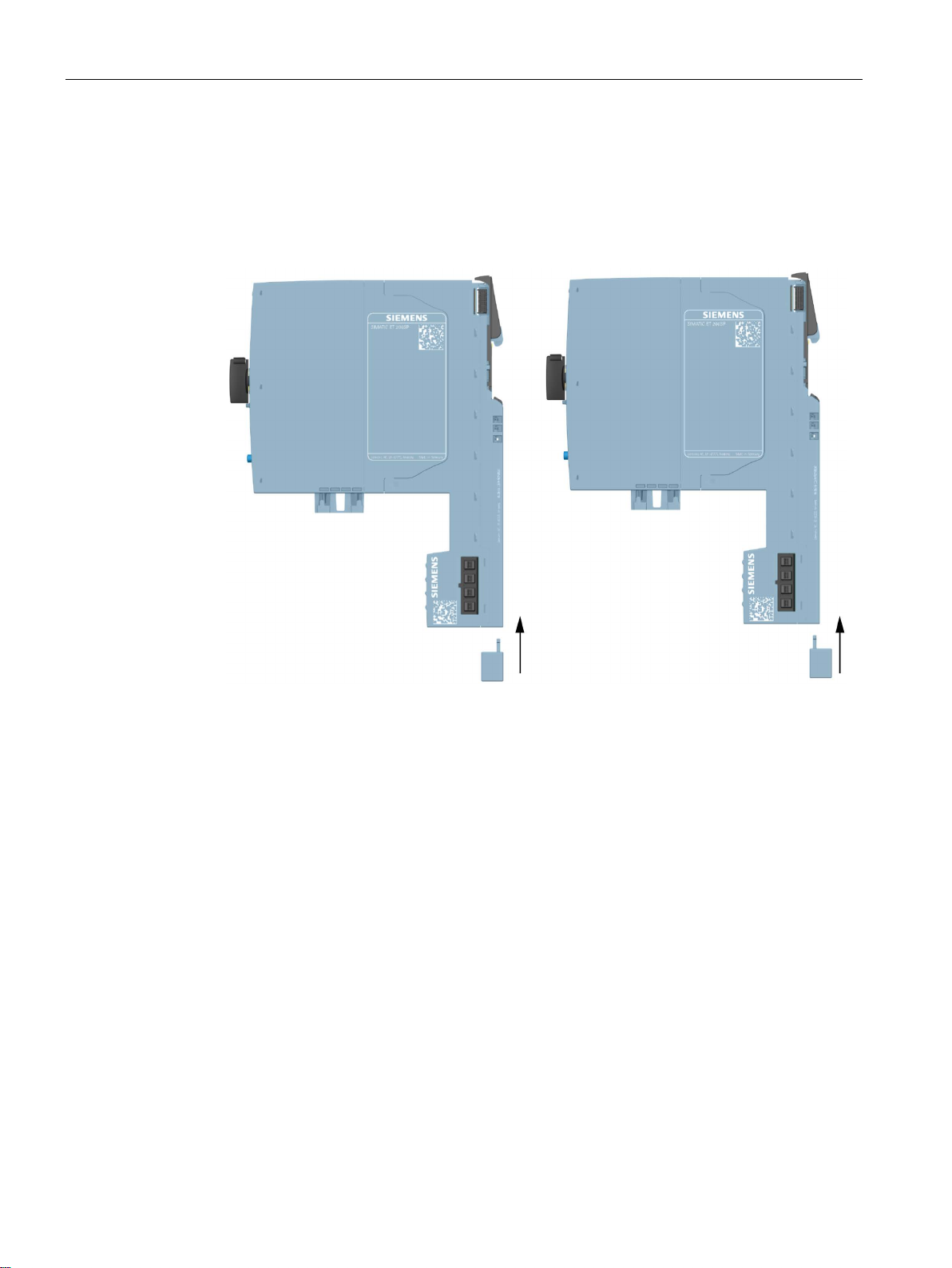
Installation
Procedure
4.8 Mounting further accessories for motor starters
To mount the mechanical bracket, proceed as follows:
1. Insert the mechanical bracket into the opening at the bottom of the BaseUnit.
You use the same mechanical bracket for both mounting rails, rotated through 180°
respectively.
2. Hook the BaseUnit into the mounting rail.
3. Insert the mechanical bracket into the BaseUnit.
4. Screw the mechanical bracket securely onto the mounting panel. Use an M4 screw and a
suitable washer.
Distributed I/O system
72 System Manual, 12/2016, A5E03576849-AG
Page 73
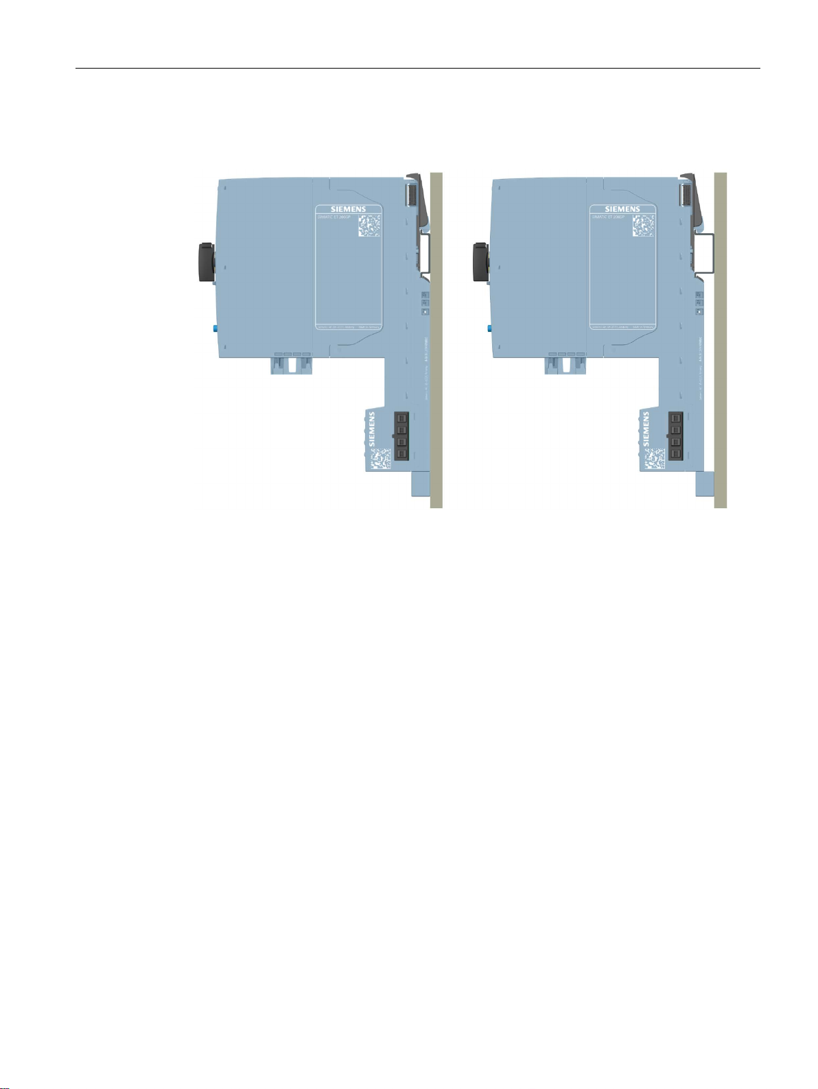
Installation
4.8 Mounting further accessories for motor starters
The figures below show the mechanical bracket after installation on a 7.5 mm or 15 mm
mounting rail.
Distributed I/O system
System Manual, 12/2016, A5E03576849-AG
73
Page 74
Installation
4.8.3
Mounting the BU cover
Introduction
DANGER
Hazardous Voltage
Can Cause Death, Serious Injury, or Property Damage.
DANGER
BaseUnit without motor starter - electric shock
Procedure
4.8 Mounting further accessories for motor starters
BU covers are plugged onto BaseUnits whose slots have been reserved for future expansion
(as empty slots). The BU covers for motor starters serve as touch protection covers for
unoccupied slots.
Hazardous electrical voltage causes electric shock, burns and property damage.
Disconnect your system and devices from the power supply before starting any assembly
tasks.
If you install a BaseUnit without motor starter in the ET 200SP system (e.g. options
handling), you must provide the BaseUnit with a BU cover (Article No: 3RK1908-1CA000BP0).
Failure to do so will result in the danger of electric shock.
To mount the BU cover onto a SIMATIC ET 200SP motor starter, insert the BU cover in the
BaseUnit in parallel until both interlocks audibly engage.
Distributed I/O system
74 System Manual, 12/2016, A5E03576849-AG
Page 75

5
5.1
Rules and regulations for operation
Introduction
Specific application
EMERGENCY STOP devices
Excluding hazardous plant states
Line voltage
When installing the ET 200SP distributed I/O system as part of a plant or system, special
rules and regulations need to be adhered to depending on the area of application.
This section provides an overview of the most important rules that must be observed for the
integration of the ET 200SP distributed I/O system in a plant or system.
Adhere to the safety and accident prevention regulations applying to specific applications, for
example machine protection guidelines.
EMERGENCY STOP devices in accordance with IEC 60204 (corresponds to DIN VDE 0113)
must remain effective in all operating modes of the plant or system.
Hazardous operating states must not occur when
● the plant restarts after a voltage dip or power failure.
● Bus communication is reestablished following a fault.
If necessary, EMERGENCY STOP must be forced!
An uncontrolled or undefined startup must not occur after the EMERGENCY STOP is
unlocked.
Below, everything you need to consider in terms of line voltage is described (refer to section
Insulation, protection class, degree of protection and rated voltage (Page 281)):
● For fixed plants or systems without an all-pole mains disconnection switch, a mains
disconnection device (all-pole) must be available in the building installation.
● For load power supplies, the configured rated voltage range must correspond to the local
line voltage.
● For all power circuits of the ET 200SP distributed I/O system, the fluctuation/deviation of
the line voltage from the rated value must be within the permitted tolerance.
Distributed I/O system
System Manual, 12/2016, A5E03576849-AG
75
Page 76

Wiring
24 V DC supply
Protection against outside electrical influences
Reference
5.1 Rules and regulations for operation
Below you will find a description of what you need to pay attention to with 24 V DC supply:
● For buildings: In the event of danger through overload, you must provide lightning
protection measures for external lightning protection (e.g. lightning protection elements).
● For 24 V DC supply lines and signal lines: If there is a risk of overvoltages, you need to
take precautions to ensure internal lightning protection (e.g. lightning protection elements,
refer to section Accessories/spare parts (Page 286)).
● For 24 V DC supply: Ensure safe (electrical) isolation and separate cable laying or
increased insulation of the extra-low voltage (SELV/PELV) to circuits with hazardous
potentials in accordance with IEC 60364-4-41.
Below is a description of what you must pay attention to in terms of protection against
electrical impacts and/or faults:
● Make sure that the system for discharging electromagnetic interference is connected to a
protective conductor with sufficient cross-section for all plants with an ET 200SP
distributed I/O system.
● For supply, signal and bus lines, you must ensure that the laying of the lines and the
installation is correct.
● For signal and bus lines, you must ensure that a wire/cable break or a cross-circuit does
not lead to undefined states of the plant or system.
You can find more information in the Designing interference-free controllers
(http://support.automation.siemens.com/WW/view/en/59193566) function manual.
Distributed I/O system
76 System Manual, 12/2016, A5E03576849-AG
Page 77
Wiring
5.2
Additional rules and regulations for the operation of the ET 200SP
with fail-safe modules
5.2.1
Safety extra low voltage for fail-safe modules and fail-safe motor starters
WARNING
WARNING
5.2 Additional rules and regulations for the operation of the ET 200SP with fail-safe modules
The fail-safe modules must be operated with safety extra low voltage (SELV, PELV).
You can find more information on safety extra-low voltage in the data sheets, for example,
of the applicable power supplies.
The fail-safe modules operate with the 24 V DC rated voltage. The tolerance range is
19.2 V DC to 28.8 V DC.
The fail-safe motor starters operate with the 24 V DC rated voltage. The tolerance range is
20.4 V DC to 28.8 V DC.
Within the overvoltage range from 32 V DC to 36 V DC, the F-modules react in a fail-safe
manner and the inputs and outputs are passivated. For overvoltages greater than 36 V DC,
the F-modules are permanently de-energized.
Use a power supply unit that does not exceed U
= 36 V DC even in the event of a fault.
m
For more on this, refer to the information in the data sheet on overvoltage protection in the
case of an internal error. Or implement appropriate measures to limit the voltage, e.g. use
of an overvoltage protector.
All system components that can supply electrical energy in any form whatsoever must fulfill
this condition.
Each additional circuit (24 V DC) used in the system must have a safety extra low voltage
(SELV, PELV). Refer to the relevant data sheets or contact the manufacturer.
Sensors and actuators with an external power supply can also be connected to F-modules.
Make sure that power is supplied to these components from safety extra-low voltage as
well. The process signal of a 24 V DC digital module may not exceed a fault voltage U
in
m
the event of a fault.
Even when a fault occurs, the permissible potential difference between the supply of the
interface module (bus voltage) and the load voltage must not be exceeded.
An external direct electrical connection is one way to meet this requirement. This also
prevents potential differences from causing voltage additions at the individual voltage
sources, which would cause the fault voltage U
to be exceeded.
m
Distributed I/O system
System Manual, 12/2016, A5E03576849-AG
77
Page 78
Wiring
Power supply requirements for compliance with NAMUR recommendations
Note
To ensure adherence to the NAMUR recommendation NE
only use power packs/power supply units (230
of at least 20 ms
Internet (
These requirements, of cours
constructed using ET
5.2.2
Requirements for sensors and actuators for fail-safe modules and fail-safe motor starters
General requirements for sensors and actuators
WARNING
safety
responsibility
5.2 Additional rules and regulations for the operation of the ET 200SP with fail-safe modules
21, IEC 61131-2 and EN 298,
V AC → 24 V DC) with a mains buffering time
. The latest up-to-date information on PS components is available on the
https://mall.industry.siemens.com).
e, also apply to power packs/power supply units not
200SP / S7-300-/400-/1500 technology.
Note the following important warning regarding safety-related use of sensors and actuators:
Note that instrumentation with sensors and actuators bears a considerable
. Also bear in mind that sensors and actuators generally do not have proof-test
intervals of 20 years as defined in IEC 61508:2010 without considerable loss of safety.
The probability of hazardous faults and the rate of hazardous faults of safety functions must
comply with an SIL-defined high limit. A listing of values achieved by F-modules in the
technical specifications of the F-modules is available under "Fail-safe performance
characteristics".
To achieve the required safety class, suitably qualified sensors and actuators are
necessary.
Distributed I/O system
78 System Manual, 12/2016, A5E03576849-AG
Page 79
Wiring
Additional sensor requirements
WARNING
Additional requirements for sensors for fail-safe motor starters
Duration requirements for sensor signals
WARNING
Reliable detection by F-modules with inputs
5.2 Additional rules and regulations for the operation of the ET 200SP with fail-safe modules
General rule: To achieve SIL3/Cat. 3/PLe, a single-channel sensor is adequate. However, to
achieve SIL3/Cat. 3/PLe with a single-channel sensor, the sensor itself must be
SIL3/Cat. 3/PLe-capable; otherwise the sensor must be connected by two channels to
achieve this safety level.
To achieve SIL3/Cat. 4/PLe, sensors must be connected by two channels.
In the case of fail-safe input modules, the value "0" is output to the F-CPU after detection of
faults. You therefore need to make sure that the sensors are implemented in such a way as
to ensure the reliable reaction of the safety program when the sensor is in the "0" state.
Example: In its safety program, an EMERGENCY-STOP sensor must achieve the
shutdown of the relevant actuator when it is in the "0" state (EMERGENCY-STOP button
pressed).
Only single-channel sensors that fulfill the required safety category themselves may be
connected to the fail-safe motor starter's F-DI. Fail-safe laying must be observed in
accordance with the required safety category.
Observe the following requirements for sensor signals:
• To ensure the correct detection of the sensor signals via fail-safe modules with inputs,
you need to make sure that the sensor signals are output for a minimum duration.
• For pulses to be detected with certainty, the time between two signal changes (pulse
duration) must be greater than the PROFIsafe monitoring time.
The minimum duration of sensor signals for F-modules with inputs depends on the
configured input delay, the parameters of the short circuit test of the sensor supplies, and the
configured discrepancy behavior for 1oo2 evaluation. The signal must be greater than the
maximum response time of the configured application. Information on calculating the
maximum response time can be found in the section "Response times" of the relevant Fmodule.
The maximum permitted switching frequency of the sensor signals results from the minimum
duration.
Distributed I/O system
System Manual, 12/2016, A5E03576849-AG
79
Page 80
Wiring
Additional requirements for actuators
WARNING
Technical specifications of sensors and actuators
5.2 Additional rules and regulations for the operation of the ET 200SP with fail-safe modules
The fail-safe output modules test the outputs at regular intervals. The F-module briefly
switches off the activated outputs and, if necessary, switches on the deactivated outputs.
You can assign the maximum duration of the test pulses (dark and light period) with
parameters.
Fast reacting actuators may briefly drop out or be activated during the test. If your process
does not tolerate this, set the pulse duration of the light or dark test correspondingly or use
actuators that have sufficient lag.
If the actuators switch voltages higher than 24 V DC (e.g. 230 V DC), safe galvanic
isolation must be ensured between the outputs of a fail-safe output module and the parts
carrying a higher voltage (in compliance with the IEC 60664-1 standard).
This is generally the case for relays and contactors. Particular attention must be paid to this
with semiconductor switching devices.
Refer to the manuals of the fail-safe modules for technical specifications to assist you in
selecting sensors and actuators.
Distributed I/O system
80 System Manual, 12/2016, A5E03576849-AG
Page 81
Wiring
5.2.3
Crosstalk of digital input/output signals
Cause: capacitive crosstalk
Remedy:
Cause: magnetic crosstalk
Remedy:
5.3
Additional rules and instructions for operation with motor starters
5.3.1
Protection against short circuit
WARNING
Hazardous Voltage at the Motor
Can Cause Death, Serious Injury, or Property Damage.
5.3 Additional rules and instructions for operation with motor starters
When fail-safe digital output and input signals are in a single cable, F-DQ modules and FPM-E modules may experience readback errors.
During the bit pattern test of the outputs or the sensor supply of the inputs, the steep
switching edge of the output drivers caused by the coupling capacitance of the line may
result in crosstalk to other non-activated output or input channels. This may then lead to a
response of the readback circuit in these channels. A cross circuit/short-circuit is detected,
which leads to safety-related tripping.
● Separate cables for F-DI modules, F-DQ modules, and F-PM-E modules or non-fail-safe
● Separate cables for F-DQ channel and F-DI channels for the F-PM-E module
● Coupling relay or diodes in the outputs
● Disable the sensor supply test if safety class requirements allow it.
Note that an inductive load connected to the F-DQ channels can induce coupling of a strong
magnetic field.
● Separate the inductive loads spatially or shield against the magnetic field.
● Configure the readback time to 50 ms or higher.
DQ modules
Distributed I/O system
System Manual, 12/2016, A5E03576849-AG
The motor starter complies with type of coordination 1. Secure the feeder cable for the infeed
bus according to current, country-specific rules for conductor protection.
Following a short-circuit, the SIMATIC ET 200SP motor starter is defective. Replace the
motor starter following a short-circuit.
81
Page 82

Wiring
5.4
Operating the ET 200SP on grounded incoming supply
Introduction
Grounded incoming supply
Safe electrical isolation (SELV/PELV in accordance with IEC 60364-4-41)
Configuration of ET 200SP with ungrounded reference potential
5.4 Operating the ET 200SP on grounded incoming supply
Below you will find information on the overall configuration of an ET 200SP distributed I/O
system on a grounded incoming supply (e.g. TN-S network). The specific subjects discussed
are:
● Disconnecting devices and short-circuit and overload protection according to IEC 60364
(corresponds to DIN VDE 0100) and IEC 60204 (corresponds to DIN VDE 0113)
● Load power supplies and load circuits.
In the case of grounded incoming supplies (TN-S system) the neutral conductor (N) and the
protective conductor (PE) are each grounded. Both conductors form a part of the overvoltage
concept. When a plant is in operation, the current flows across the neutral conductor. When
a fault occurs, for example, a single ground fault between a live conductor and ground, the
current flows through the protective conductor.
Load current / power supply modules with safe electrical isolation are required for the
operation of the ET 200SP distributed I/O system. According to IEC 60364-4-41, this
protection is referred to as SELV (Safety Extra Low Voltage)/PELV (Protective Extra Low
Voltage).
The wiring of SELV/PELV circuits must either be isolated from the wiring of other circuits that
are not SELV/PELV or the insulation of all conductors must be dimensioned for the higher
voltage.
To conduct interference currents, the reference potential of the CPU/interface module and
the BaseUnits BU15...D is connected internally via an RC combination (IM/CPU:
R = 10 MΩ / C = 100 nF, BU15...D: R = 10 MΩ / C = 4 nF) with the mounting rail (protective
conductor).
● This configuration conducts high-frequency interference currents and prevents static
charges.
● It is always possible to configure an ungrounded setup of the ET 200SP distributed I/O
system as the ET 200SP distributed I/O system has no fixed ground connection. The
power pack/power supply module for 24 V DC must also be ungrounded and electrically
isolated.
If you want to configure the ET 200SP distributed I/O system with grounded reference
potential, connect the 1M connection of the CPU/interface module electrically with the
protective conductor.
Distributed I/O system
82 System Manual, 12/2016, A5E03576849-AG
Page 83

Wiring
Short-circuit / overload protection
Refer to figure
IEC 60364 (DIN VDE 0100)
IEC 60204 (DIN VDE 0113)
sensors, and actuators
②
③
single-pole
all-pole
electromagnetic equipment
recommended
recommended
Permissible cable temperature
Note
Permissible cable temperature
The minimum permissible cable temperature must be 30
temperature of the ET
connection conductor must be dimensioned for a temperature range of at least 90
You should specify other connection types and material requirements based on the electrical
characteristics of the circuits you
5.4 Operating the ET 200SP on grounded incoming supply
Various measures as protection against short-circuits and overloads are required for setting
up a full installation. The type of components and the binding protective measures depend
on which IEC (DIN VDE) regulation applies to your system configuration. The table refers to
the figure below and compares the IEC (DIN VDE) regulations.
Table 5- 1 Components and protective measures
Disconnecting device for controller,
Short-circuit / overload protection:
In groups for sensors and actuators
Load current supply for AC load circuits with more than five items of
①
②
Main switch Disconnector
Single-pole protection of
circuits
Galvanic isolation by transformer
With grounded secondary
circuit:
otherwise:
Galvanic isolation by transformer
protection
protection
°C more than the ambient
200SP system (example: at an ambient temperature of 60 °C, a
°C).
use and the installation environment.
Distributed I/O system
System Manual, 12/2016, A5E03576849-AG
83
Page 84
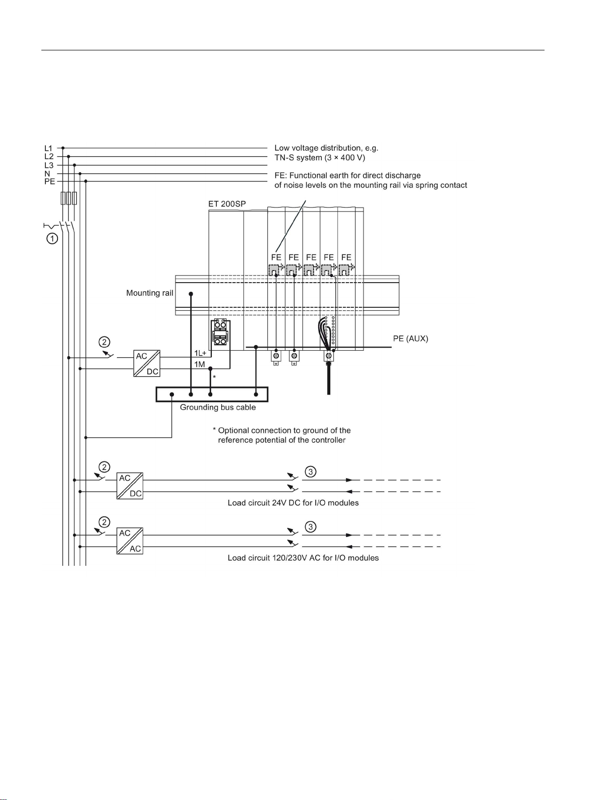
Wiring
ET 200SP in the overall configuration
①
Main switch
②
Short-circuit / overload protection
③
The load current supply (galvanic isolation)
5.4 Operating the ET 200SP on grounded incoming supply
The figure below shows the overall configuration of the ET 200SP distributed I/O system
(load current supply and grounding concept) with supply from a TN-S network.
Figure 5-1 ET 200SP in the overall configuration
Distributed I/O system
84 System Manual, 12/2016, A5E03576849-AG
Page 85
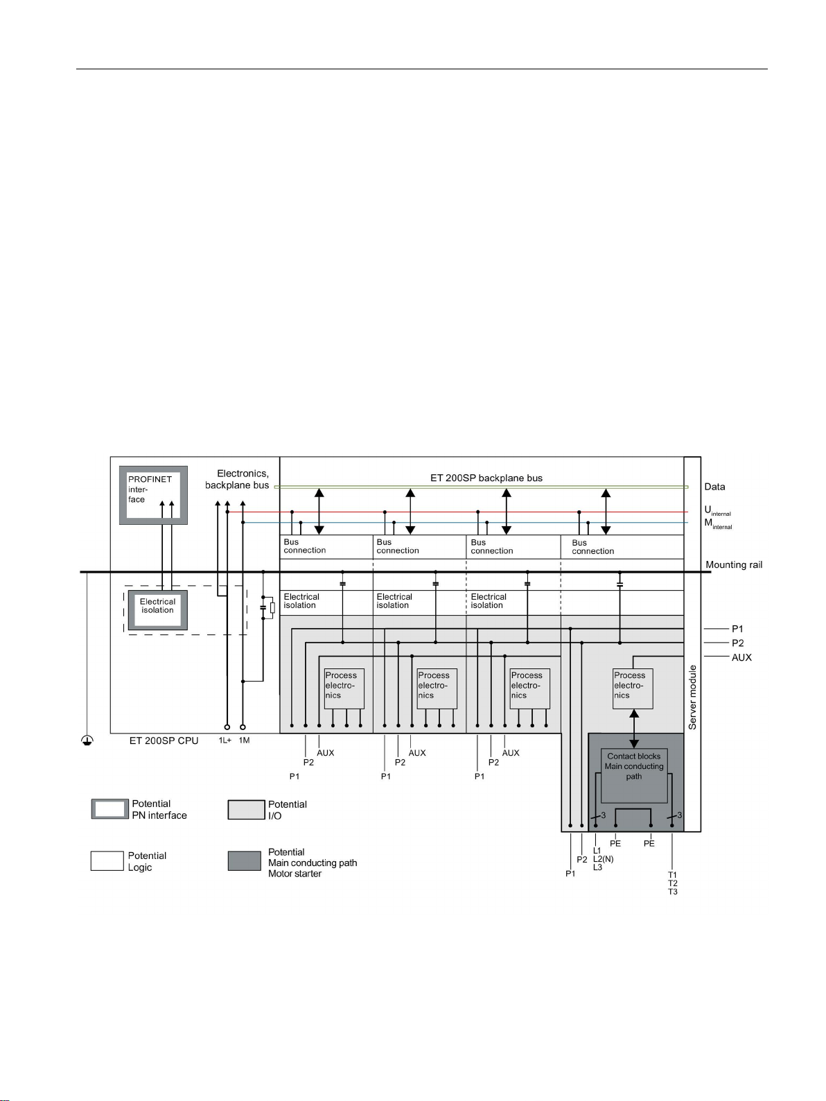
Wiring
5.5
Electrical configuration of the ET 200SP
Electrical isolation
Electrical relationships
5.5 Electrical configuration of the ET 200SP
With the ET 200SP distributed I/O system, there is electrical isolation between:
● The load circuits/process and all other circuit components of the ET 200SP distributed I/O
system.
● The communication interfaces of the CPU (PROFINET) or of the interface module
(PROFINET/PROFIBUS) and all other circuit components.
The figures below show the electrical relationships of the ET 200SP distributed I/O system
with the CPU and the interface module. Only the most important components are
represented in the figures.
Figure 5-2 Electrical relationships for ET 200SP with CPU
Distributed I/O system
System Manual, 12/2016, A5E03576849-AG
85
Page 86
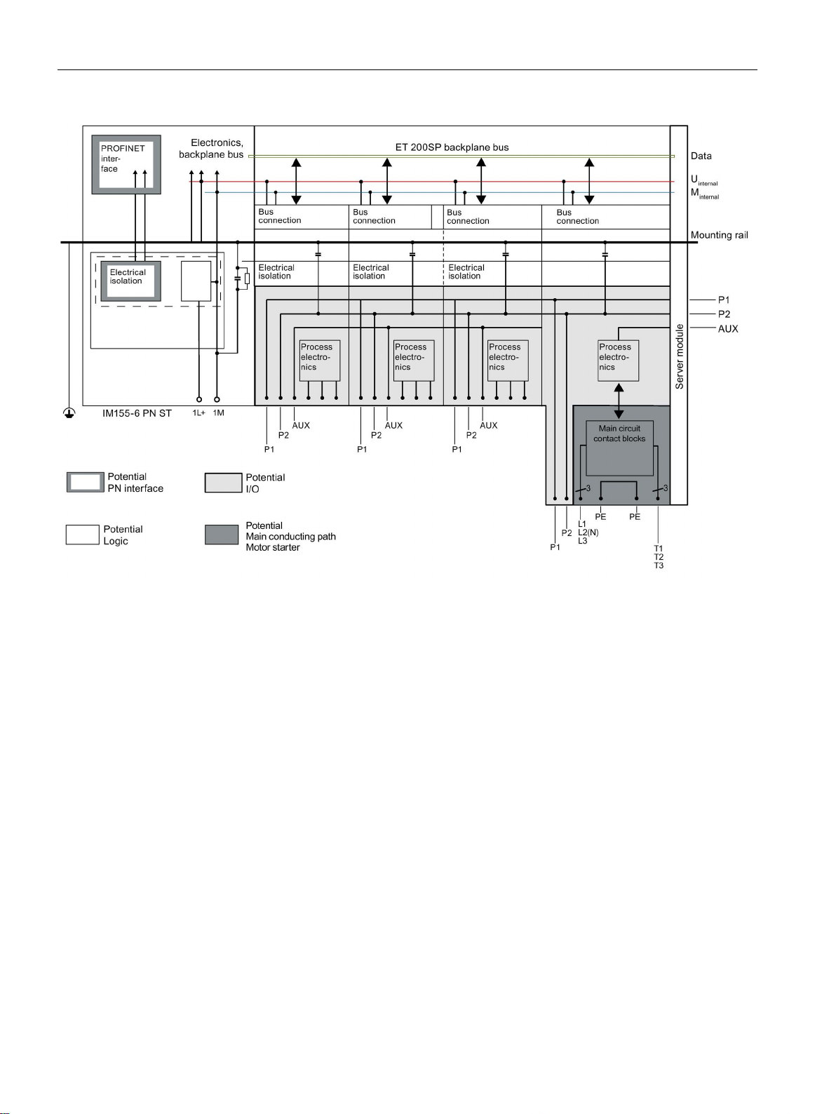
Wiring
5.5 Electrical configuration of the ET 200SP
Figure 5-3 Electrical relationships for ET 200SP with interface module (using IM 155-6 PN ST as an example)
Distributed I/O system
86 System Manual, 12/2016, A5E03576849-AG
Page 87

Wiring
5.6
Wiring rules
Wiring rules for the CPU/interface module and BaseUnits for I/O modules
Wiring rules for ...
CPU/interface module (supply
voltage)
BaseUnits
(push-in terminal)
0.2 to 2.5 mm2
0.2 to 2.5 mm2
AWG*: 24 to 13
AWG*: 24 to 14
0.25 mm to 1.5 mm
0.14 mm to 1.5 mm2
AWG*: 24 to 16
AWG*: 26 to 16
0.5 mm to 1 mm2
0.5 to 0.75 mm2 (see below)
AWG*: 20 to 17
AWG*: 20 to 18
Stripping length of the wires
8 to 10 mm
plastic sleeve
* AWG: American Wire Gauge
** End sleeves without plastic sleeve: 0.25 to 2.5
*** See note on end sleeves
Note
End sleeves
Optimum results with respect to a high
maximum conductor pull forces at the same time can be achieved by using crimping dies,
preferably with smooth surfaces, which are provided, for example, with rectangular and
trapezoidal crimp cross
Due to the large num
request. Crimping dies with a pronounced wave profile are unsuitable.
5.6 Wiring rules
Connectable cross-sections for solid cables
AWG*: 24 to 13
Connectable crosssections for flexible
cables
Without end sleeve
With end sleeve (with plastic sleeve)
With TWIN end sleeve
***
***
2**
End sleeves in accordance with DIN 46228 with
***
ber of crimping dies used in the industry, we can recommend others on
8 and 10 mm long
mm2/AWG: 24 to 13
-quality and permanent electrical connection with
-sections.
Distributed I/O system
System Manual, 12/2016, A5E03576849-AG
87
Page 88
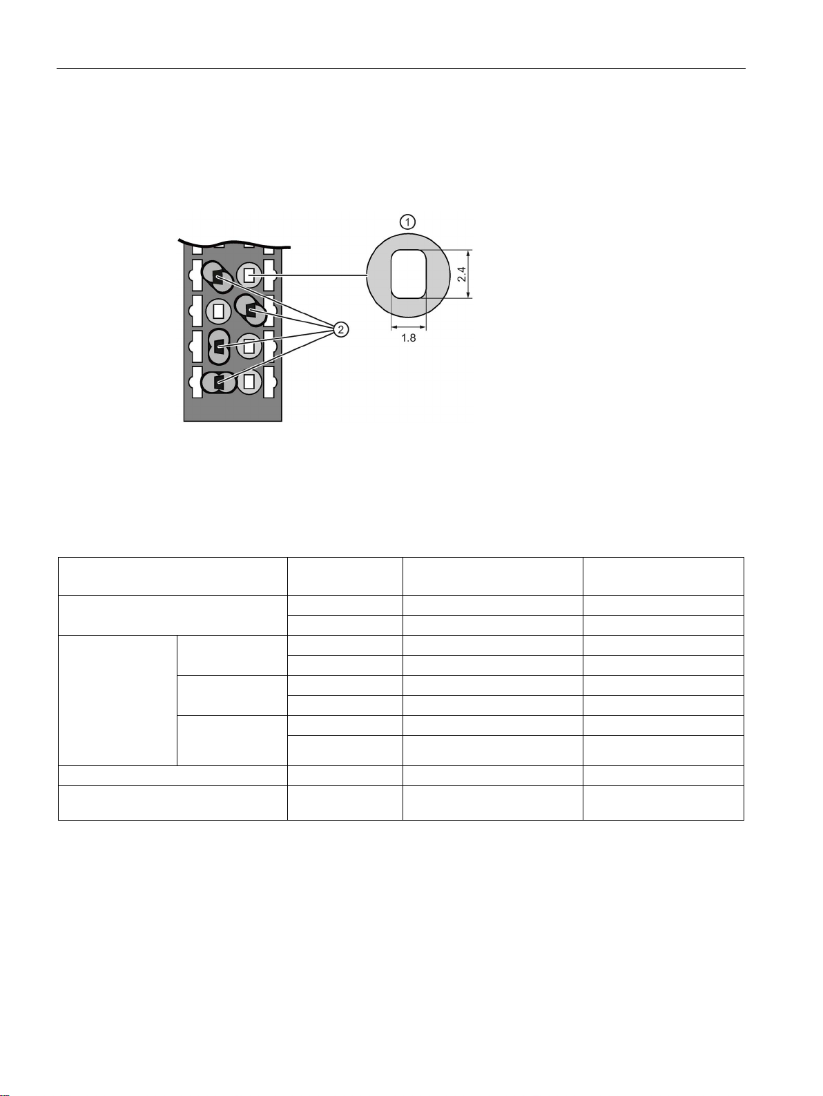
Wiring
TWIN end sleeves for the cables of the I/O modules' push-in terminals
①
Cross-section of the terminal compartment
②
Crimping TWIN end sleeves at the correct angle
Wiring rules for motor starters
Wiring rules for ...
L1(L), L2(N), L3,
PE
T1, T2, T3, PE, 24 V DC, F-DI,
M
DI1 ... DI3, LC, M, 24 V
OUT
1 to 6 mm2
0.5 to 2.5 mm2
0.2 to 1.5 mm2
AWG: 18 to 10
AWG: 20 to 12
AWG: 24 to 16
1 to 6 mm2
0.5 to 2.5 mm2
0.2 to 1.5 mm2
AWG: 18 to 10
AWG: 20 to 12
AWG: 24 to 16
1 to 6 mm2
0.5 to 2.5 mm2
0.25 to 1.5 mm2
AWG: 18 to 10
AWG: 20 to 12
AWG: 24 to 16
sleeve)
1 to 4 mm2
0.5 to 1.5 mm2
0.25 to 0.75 mm2
with plastic sleeve
5.6 Wiring rules
Due to the space required by TWIN end sleeves with 0.75 mm2 cross-section, you must
ensure a correct angle for the cable arrangement when crimping the TWIN end sleeve so
that the cables are optimally arranged.
Figure 5-4 TWIN end sleeves
Connectable cross-sections for solid
cables
Connectable crosssections for flexible
cables
Stripping length of the wires 15 mm 10 mm 8 mm
End sleeves according to DIN 46228
Without end
sleeve
With end sleeve
With end sleeve
(with plastic
AWG: 18 to 11 AWG: 20 to 16 AWG: 24 to 18
15 mm long 10 mm long 8 mm long
Distributed I/O system
88 System Manual, 12/2016, A5E03576849-AG
Page 89

Wiring
Safety standards for fail-safe motor starters
Line protection
Permissible cable temperature
Note
Permissible cable temperature
The minimum permissible cable temperature must be 30
temperature of the ET
conductor must be dimensioned for a temperature range
You should specify other connection types and material requirements based on the electrical
characteristics of the circuits you use and the installation environment.
5.6 Wiring rules
Fail-safe motor starters fulfill the following standards under certain conditions:
● PL e/Cat. 4 according to EN ISO 13849-1
● Safety Integrity Level SILCL3 acc. to IEC 62061
To fulfill both standards, lay cross-circuit proof and P-cross-circuit proof control cables from
the safe output of a sensor or F-DQ to the safe input of the motor starter, e.g. as a
separately sheathed cable or in a separate cable duct.
The line protection of the SIMATIC ET 200SP motor starter is provided for the motor
outgoing feeder cable when the following condition is met:
The cross-section of the motor outgoing feeder cable must be dimensioned for the load
ratios of the motor and for the cable-laying method.
Comply with national regulations. The user is responsible for the correct selection and
dimensioning of the motor connection cable to DIN VDE 0100 and DIN VDE 0298-4 and/or
UL 508.
The conductor protection for the incoming feeders must be ensured by the owner of the
installation depending on the cross-section.
°C higher than the ambient
200SP (example: at an ambient temperature of 60 °C, a connection
of at least 90 °C).
Distributed I/O system
System Manual, 12/2016, A5E03576849-AG
89
Page 90
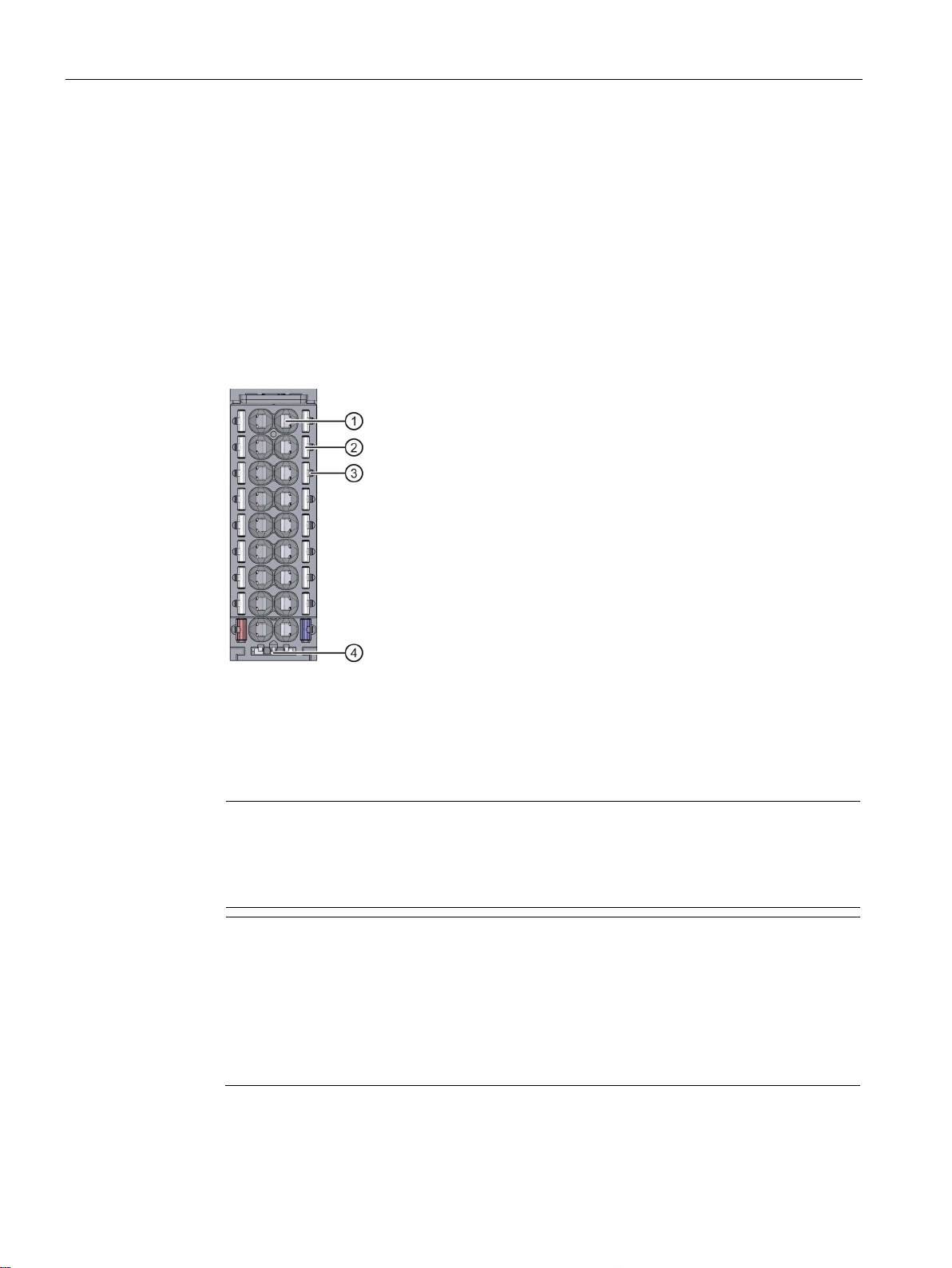
Wiring
5.7
Wiring BaseUnits for I/O modules
Introduction
①
Push-in terminal
②
Spring release
③
permitted voltage category)
④
Holder for shield connection
Note
The pin assignment of the BaseUnit depends on the connected I/O module. Information
on the BaseUnits and I/O modules can be found in the associated manuals.
Replacement of the terminal box on the BaseUnit is described in the section
the terminal box on the BaseUnit
Note
Special terminal designations in the wiring and block diagrams of the I/O
modules/BaseUnits
• RES
• n.c.
5.7 Wiring BaseUnits for I/O modules
The BaseUnits connect the ET 200SP distributed I/O system to the process. The following
versions of the BaseUnits can be used:
● BaseUnits (with light-colored terminal box) for opening a potential group: BU..D
● BaseUnits (with dark-colored terminal box) for extending the potential group: BU..B
● BaseUnits with additional AUX terminals or additional terminals: BU..+10..
● BaseUnits with integrated thermal resistor for compensation of the reference junction
temperature when connecting thermocouples: BU..T
Measuring probe (suitable probes: 1 mm diameter, length ≥ 10 mm while observing the
Figure 5-5 View of the BaseUnit
(Page 243).
: Reserve, these terminals must remain unconnected so that they can be used for
future expansions
: Not connected, these terminals have no function. However, they can be
connected to potentials specifically defined for a module, for example, for the laying
unused wires.
Distributed I/O system
90 System Manual, 12/2016, A5E03576849-AG
Replacing
Page 91

Wiring
Requirements
Required tools
Tool-free connection of cables: single-wire without wire end ferrule, multi-wire (stranded) with wire
end ferrule or ultrasonically sealed
Connection of cables: multi-wire (stranded), without wire end ferrule, unprocessed
Removing wires
Note
When you press the spring release, you should not pull on the wire/cable at the same time.
This prevents you from damaging the terminal.
5.7 Wiring BaseUnits for I/O modules
● The supply voltages are turned off.
● Follow the wiring rules.
● Color identification labels (Page 137) (optional) have been applied.
3 to 3.5 mm screwdriver
Watch the video sequence (http://support.automation.siemens.com/WW/view/en/95886218)
To connect a wire without tools, follow these steps:
1. Strip 8 to 10 mm of the wires.
2. Only for multi-stranded wires:
Seal or crimp the wire with wire end ferrules.
3. Insert the wire into the push-in terminal as far as it will go.
To connect a wire without a wire end ferrule, follow these steps:
1. Strip 8 to 10 mm of the wires.
2. Push with the screwdriver into the spring release.
3. Insert the wire into the push-in terminal as far as it will go.
4. Pull the screwdriver out of the spring release.
Using the screwdriver, press the spring release of the terminal as far as it will go and pull out
the wire.
Distributed I/O system
System Manual, 12/2016, A5E03576849-AG
91
Page 92
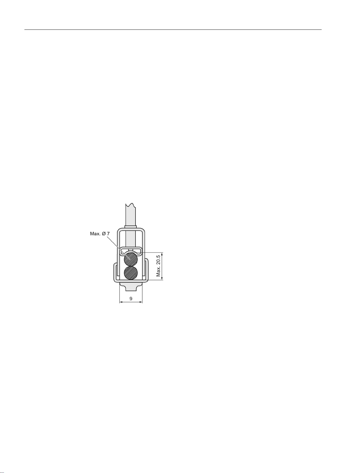
Wiring
5.8
Connecting cable shields for I/O modules
Introduction
Requirements
Required tools
5.8 Connecting cable shields for I/O modules
● You need the shield connector to contact cable shields (e.g. for analog modules). The
shield connector conducts interference currents on cable shields to ground via the
mounting rail. It is not necessary to contact the shield at where the cable enters the
cabinet.
● Attach the shield connector to the BaseUnit.
● The shield connector consists of a shield contact and a shield terminal.
● The shield connector is automatically connected to the functional ground (FG) of the
mounting rail after installation.
● BaseUnit with a width of 15 mm
● The shield terminal is suitable for cables with max. ∅ 7 mm each.
Figure 5-6 Shield terminal
● Stripping tool
Distributed I/O system
92 System Manual, 12/2016, A5E03576849-AG
Page 93
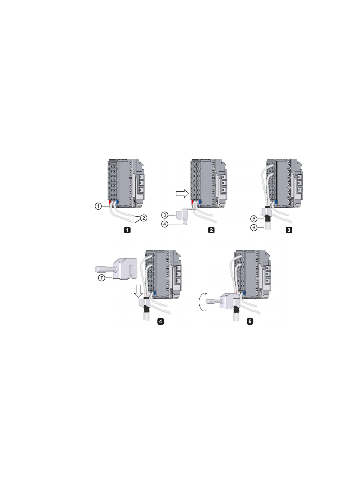
Wiring
Procedure
①
⑤
mm)
②
Supply voltage L+, ground
⑥
Cable to the encoder
③
Shield contact
⑦
Shield terminal
④
(6.3 × 0.8 mm)
5.8 Connecting cable shields for I/O modules
Watch the "Wiring BaseUnits" video sequence
(http://support.automation.siemens.com/WW/view/en/95886218)
To connect the cable shield, follow these steps:
1. If necessary, connect the supply voltage L+ and ground to the BaseUnit.
2. Press the shield contact up into the mount until you hear it click into place.
3. Remove the cable insulation material around the shield terminal.
Connect the cable to the BaseUnit and place the cable in the shield contact.
4. Insert the shield terminal into the shield contact.
5. Tighten the shield terminal with approximately 0.5 Nm.
Distributed I/O system
System Manual, 12/2016, A5E03576849-AG
Mount
Flat connector for push-on contacts
Figure 5-7 Mounting the shield contact
Insulation material removed (approx. 20
93
Page 94
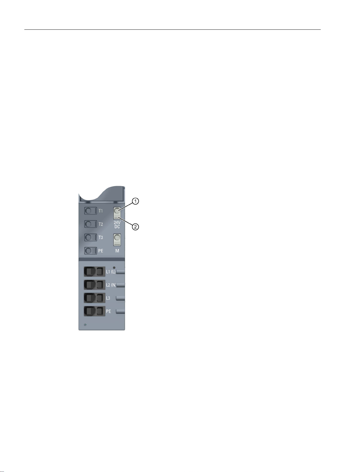
Wiring
5.9
Wiring BaseUnits for motor starters
Introduction
①
Push-in terminal
②
Spring release
5.9 Wiring BaseUnits for motor starters
The following versions of BaseUnits can be used:
● BU30-MS1 (with 500 V and 24 V infeed)
● BU30-MS2 (with 500 V infeed and 24 V forwarding)
● BU30-MS3 (with 24 V infeed and 500 V forwarding)
● BU30-MS4 (with 500 V and 24 V forwarding)
● BU30-MS5 (with 500 V infeed, 24 V and F-DI forwarding)
● BU30-MS6 (with 500 V, 24 V and F-DI forwarding)
The following figure shows an example of a BaseUnit BU30-MS1 (with the maximum number
of terminals):
Distributed I/O system
94 System Manual, 12/2016, A5E03576849-AG
Figure 5-8 Terminals on a BaseUnit BU30-MS1
Page 95
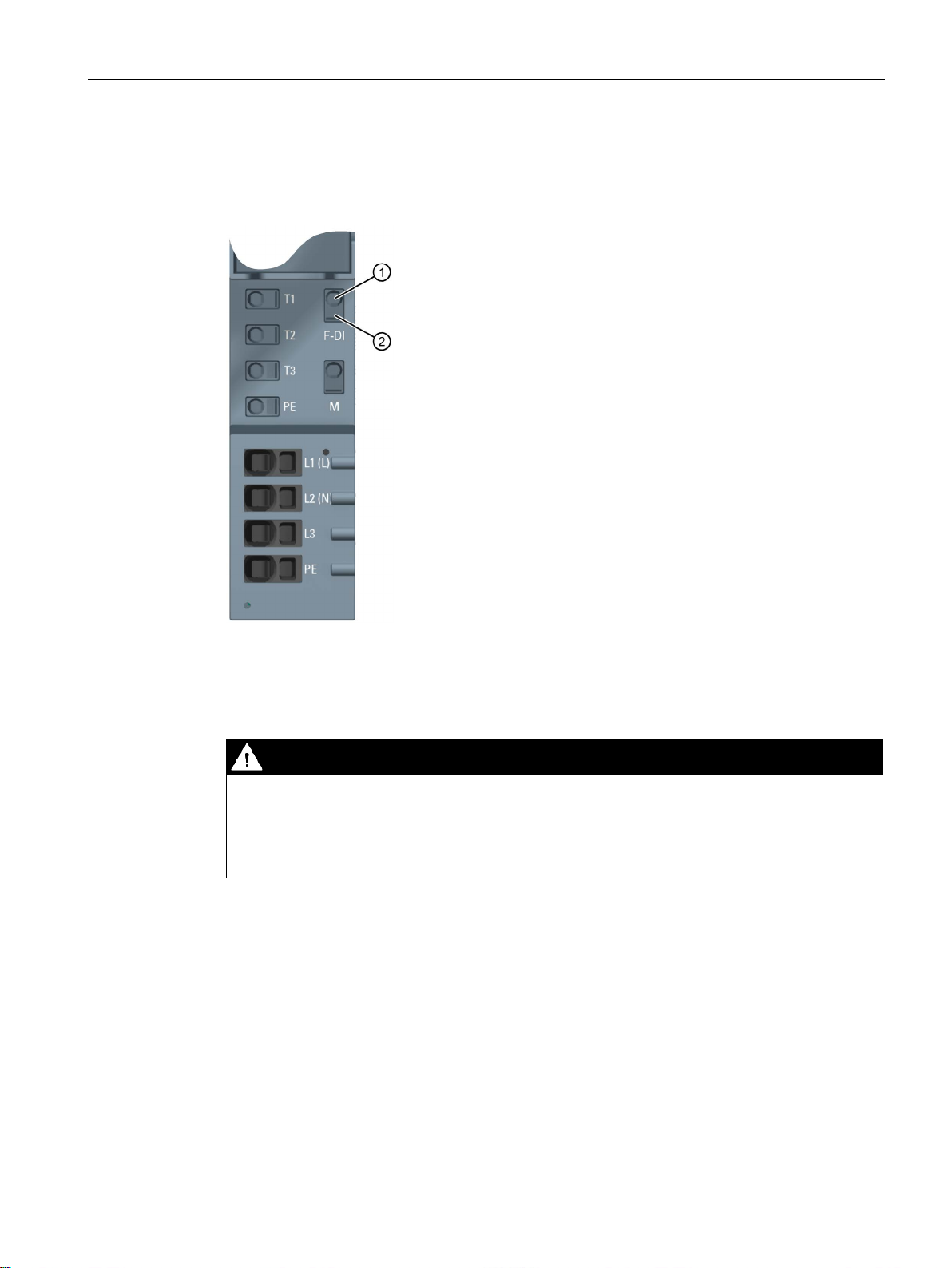
Wiring
①
Push-in terminal
②
Spring release
DANGER
Hazardous Voltage
Can Cause Death, Serious Injury, or Property Damage.
Requirements
Required tools
5.9 Wiring BaseUnits for motor starters
The following figure shows an example of a BaseUnit BU30-MS5 (with the maximum number
of terminals):
Figure 5-9 Terminals on a BaseUnit BU30-MS5
Hazardous electrical voltage can cause electric shock, burns and property damage.
Turn off and lock out all power supplying this device before working on this device.
For wiring finely-stranded or stranded conductors without end sleeves on push-in
connections, a screwdriver is required.
● The supply voltages are switched off
● Observe the wiring rules
Use the screwdriver "SZF 1-0.6x3.5" (for finely-stranded cables only).
Distributed I/O system
System Manual, 12/2016, A5E03576849-AG
95
Page 96

Wiring
Connecting conductors: Solid without end sleeve, stranded (stranded wire) with end sleeve
Connecting conductors: multi-wire (stranded), without end sleeve, unfinished
Video sequence
Releasing conductors
Note
When pressing the spring release, you must not pull on the wire/cable at the same time. In
this way, you avoid damaging the terminal.
5.9 Wiring BaseUnits for motor starters
To connect a cable, proceed as follows:
1. Insulate the cables in accordance with the table in chapter "Wiring rules (Page 87)".
2. Only in the case of stranded conductors:
Crimp the cable with end sleeves.
3. Insert the cable into the push-in terminal as far as it will go.
4. Pull on the cable to ensure it is tight.
To connect a cable, proceed as follows:
1. Insulate the cables in accordance with the table in chapter "Wiring rules (Page 87)".
2. Press the screwdriver into the spring release.
3. Insert the conductor into the push-in terminal until it engages.
4. Pull the screwdriver out of the spring release.
5. Check whether or not the conductor is firmly connected by pulling on the cable.
At the following Internet link, you can see a video about connecting conductors: Wire
BaseUnits (http://support.automation.siemens.com/WW/view/en/95886218)
To release a conductor, proceed as follows:
1. Press the screwdriver into the spring release of the terminal until it engages.
2. Pull the conductor out.
Distributed I/O system
96 System Manual, 12/2016, A5E03576849-AG
Page 97
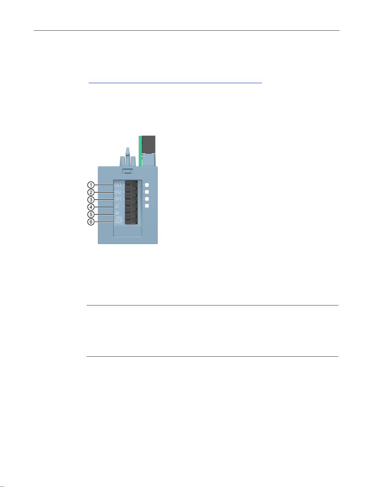
Wiring
5.10
Connecting the 3DI/LC module for the motor starter
Procedure
①
Digital input 3
②
Digital input 2
③
Digital input 1
④
Local control (manual local)
⑤
Ground
⑥
24 V DC/ 100 mA output
Note
The digital inputs (1 to 4) are not isolated. The reference potential is M (5). Control the digital
inputs only via a unit supplied from the 24
Connect only cables of a width not exceeding 30
The supply (5 and 6) is protected against short
5.10 Connecting the 3DI/LC module for the motor starter
You will find further information on the 3DI/LC module in the ET 200SP motor starter
(https://support.industry.siemens.com/cs/ww/en/view/109479973) manual.
The figure below shows the connections of the 3DI/LC module.
V DC output (6).
m to the 3DI/LC module.
-circuits.
Distributed I/O system
System Manual, 12/2016, A5E03576849-AG
97
Page 98
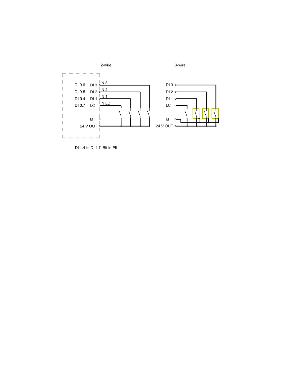
Wiring
Terminal sketch of the 3DI/LC module
5.10 Connecting the 3DI/LC module for the motor starter
The following diagram shows a terminal sketch of the 3DI/LC module:
Figure 5-10 Connection example of inputs
Distributed I/O system
98 System Manual, 12/2016, A5E03576849-AG
Page 99
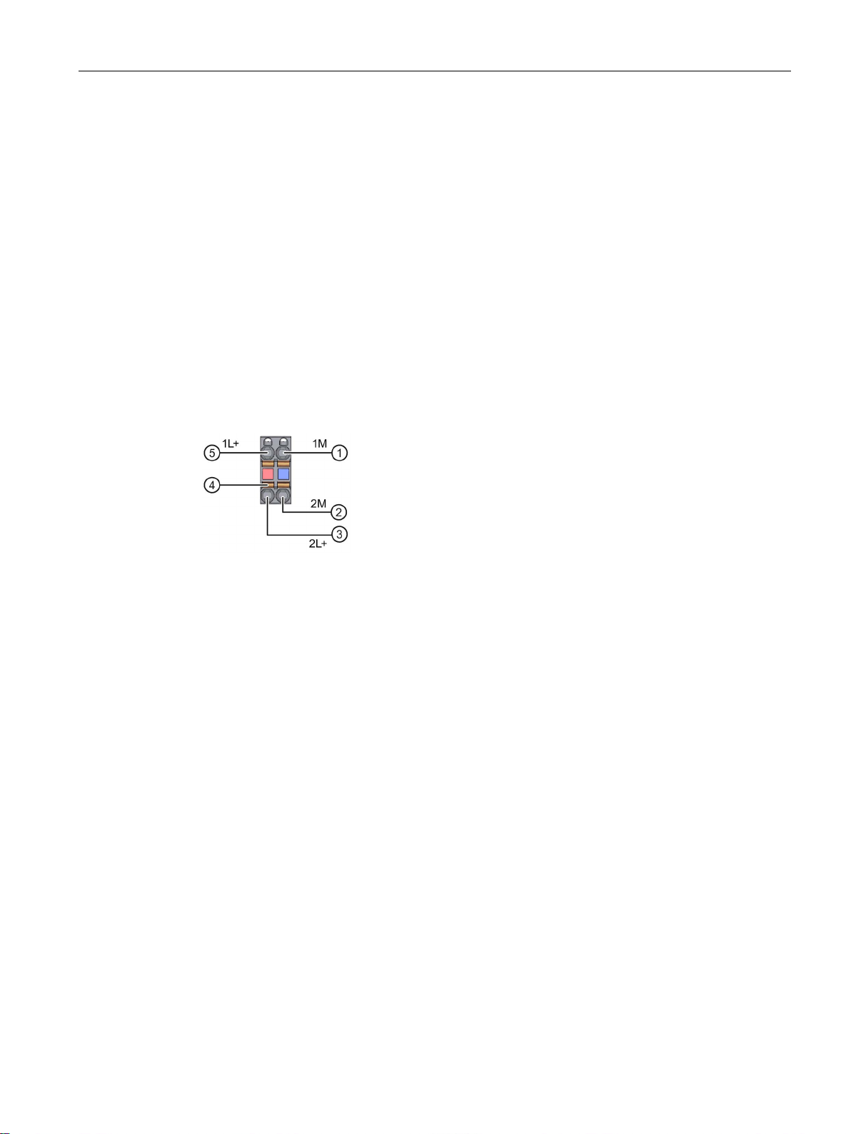
Wiring
5.11
Connecting the supply voltage to the CPU/interface module
Introduction
Power supply unit
Connection for supply voltage (X80)
①
Ground of the supply voltage
②
Ground of the supply voltage for looping through (permitted value 10 A)
③
+ 24 V DC of the supply voltage for looping through (permitted value 10 A)
④
Spring release
⑤
1L+ and 2L+ and 1M and 2M are internally jumpered.
Requirements
Required tools
5.11 Connecting the supply voltage to the CPU/interface module
The supply voltage of the CPU/interface module is supplied by means of a 4-pin connector
plug located on the front of the CPU/interface module.
Only use power supply units of type SELV/PELV with safe electrically isolated functional
extra low voltage (≤ 28.8 V DC).
The connections have the following meaning:
+ 24 V DC of the supply voltage
Figure 5-11 Supply voltage connection
The maximum cross-section of the connection is 2.5 mm2. A strain relief is not present. The
connector plugs provide you with the option of looping the supply voltage through without
interruption, even when it is unplugged.
● Only wire up the connector plug when the supply voltage is turned off.
● Follow the wiring rules (Page 87).
3 to 3.5 mm screwdriver
Distributed I/O system
System Manual, 12/2016, A5E03576849-AG
99
Page 100

Wiring
Tool-free connection of cables: single-wire without end sleeve, multi-wire (stranded) with end sleeve
or ultrasonically sealed
Connection of cables: multi-wire (stranded), without end sleeve, unfinished
Removing a wire
5.11 Connecting the supply voltage to the CPU/interface module
Watch video sequence: "Connect BusAdapter to the interface module"
(http://support.automation.siemens.com/WW/view/en/95886218)
To connect a wire without tools, follow these steps:
1. Strip 8 to 10 mm of the wires.
2. Only in the case of stranded conductors:
Seal or crimp the wire with end sleeves.
3. Insert the cable into the push-in terminal as far as it will go.
4. Push the wired connector plug into the plug socket of the interface module.
To connect a wire without an end sleeve, follow these steps:
1. Strip 8 to 10 mm of the wires.
2. Using a screwdriver, press the spring release and insert the wire into the push-in terminal
as far as it will go.
3. Pull the screwdriver out of the spring release.
4. Push the wired connector plug into the socket in the interface module.
Using the screwdriver, press the spring release as far as it will go and pull out the wire.
Distributed I/O system
100 System Manual, 12/2016, A5E03576849-AG
 Loading...