

Siemens SIM-16RC Installation Instructions Manual
Installation Instruct ions
Model SIM-16RC
Supervised Input Module Ribbon Cable
INTRODUCTION The Model SIM-16RC Supervised Input Module Ribbon
Cable from Siemens Industry, Inc., is a remotely located,
general purpose input module. It provides sixteen input
circuits for remote system monitoring. Each input can
only be unsupervised (general-purpose input). The
SIM-16RC has two Form C relays. The relays and the
inputs are programmed by inserting an SIM-16 in the
Zeus Programming Tool.
Inputs must be programmed as unsupervised.
OPERATION The SIM-16RC is mounted in an enclosure that is
remotely located from the Main Panel. Communication
between the SIM-16RC and the NIC-C (Network Interface
Card) or DAC-NET is through the Control Area Network
(CAN) bus. Up to 99 SIM-16RCs can be used with a
single NIC-C or DAC-NET.
Each SIM-16RC has two 10-position rotary switches that
are used to set the board address on the CAN which is a
sub-address of the NIC-C or DAC-NET.
Every time a change of state of the input is detected, a
unique CAN message is sent to the NIC-C or DAC-NET. A
CAN message from the NIC-C or DAC-NET directed to
the SIM-16RC controls the Form C relays.
TB3
6
1
SIM-16RC
2
1
P2
S1 S2
15
16
16
J1
15
P3
5
5
6
6
4
4
7
7
3
3
8
8
2
2
9
9
1
1
0
0
TB4
6
1
1
J2
2
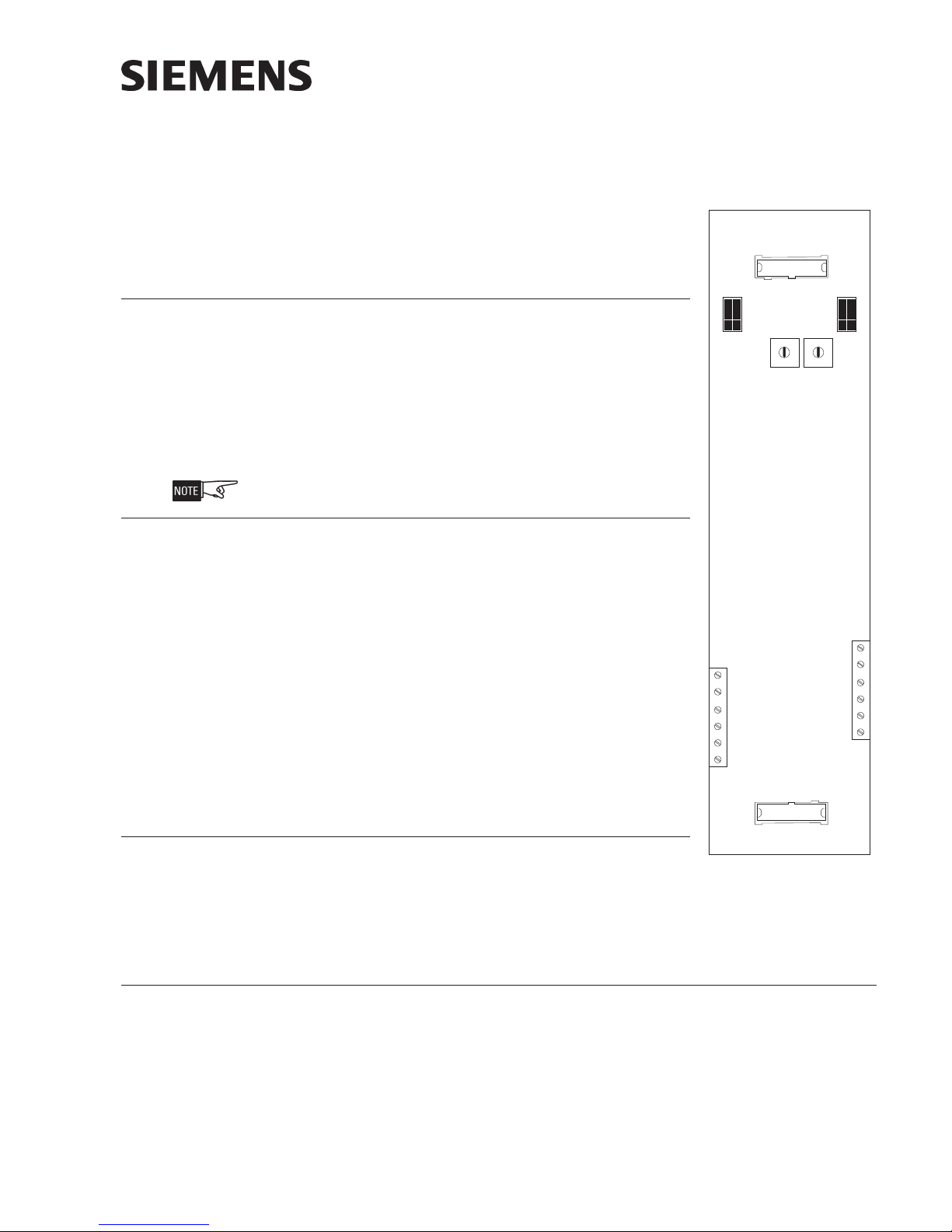
PRE-INSTALLATION Rotary Address Switches - Set the board address for
each SIM-16RC using both of the ten-position rotary
switches located on the board (See Figure 1). Each of
these addresses must be a sub-address of the NIC-C or
DAC-NET and must be the same as the addresses
assigned in the Zeus Programming Tool.
INSTALLATION A SIM-16RC may be installed in a REMBOX. When using REMBOX 2 or 4, mount the
SIM-16RC in one module space on a REMBOX2-MP, P/N 500-634211 or REMBOX4MP, P/N 500-634212 using the four screws provided. (Refer to REMBOX2-MP/
REMBOX4-MP Installation Instructions, P/N 315-034211.) Up to 4 SIM-16RCs will fit
in a REMBOX2; up to 8 SIM-16RCs will fit in a REMBOX4.
P/N 315-050715-1
Building Building
Building
Building Building
Figure 1
SIM-16RC Supervised
Input Module Ribbon
Cable
Siemens Siemens
Siemens
Siemens Siemens
TT
ecec
hnologies Dihnologies Di
T
ec
hnologies Di
TT
ecec
hnologies Dihnologies Di
IndustryIndustry
Industry
IndustryIndustry
,,
Inc. Inc.
,
Inc.
,,
Inc. Inc.
visionvision
vision
visionvision
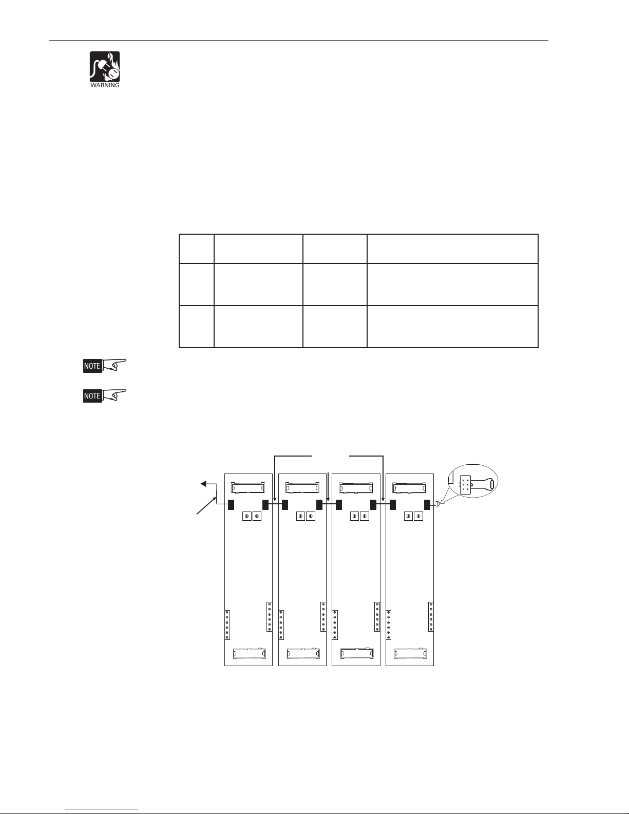
WIRING Refer to Figures 2-5.
Remove all system power before installation, first battery then AC. (To power up,
connect the AC first, then the battery.)
• Each SIM-16RC module is a node in the CAN bus.
• The SIM-16RC can be installed with or without an RNI. Connect the CAN
bus and 24V as shown in Figures 2 and 3.
• Up to 99 CAN modules, in any combination, can be connected to the CAN
bus of each NIC-C or DAC-NET.
• Each SIM-16RC module is shipped with one CCS cable.
• Cable connections for SIM-16RC modules are shown in the following table:
elbaCnoitpircseDrebmuNtraPnoitcennoC
SNOITCENNOCELBACCR61-MIS
LCCgnoL-ELBAC-NAC
412436-995.C
rotcudnoc-6,.ni03
SCCtrohS-ELBAC-N
AC
935331-555-MISotseludomCR61-MISstcennoC
rotcudnoc-6,.ni½5
dom
worelgnisaniselu
The CAN bus requires a 120S termination at each end of the loop. Refer to the NIC-C
Installation Instructions, P/N 315-033240 for details about CAN termination.
The ribbon cable for J1 and J2 is to be provided with the external unit.
CABLE
MODEL
# CCS
TO RNI, P4
CABLE
MODEL
2
J1
1
P2
5
6
4
7
3
8
2
9
1
0
S1 S2
2
16
1
15
P3
5
6
4
7
3
8
2
9
1
0
P2
J1
5
6
4
7
3
8
2
9
1
0
S1 S2
16
2
15
P3
5
6
4
7
3
8
2
9
1
0
J1
1
P2
5
6
4
7
3
8
2
9
1
0
S1 S2
2
16
1
15
P3
5
6
4
7
3
8
2
9
1
0
P2
J1
5
6
4
7
3
8
2
9
1
0
S1 S2
16
15
P3
CAN TERMINATOR,
5
6
4
7
3
8
2
9
1
0
P/N 110-134215
(SHIPPED WITH NIC-C)
# CCL
SIM-16RC SIM-16RC SIM-16RC SIM-16RC
R61-MIStsrifotINRno4PstcennoC
/MCFotCR61-MISmorfstcennocoslA
.)roodno(seludomBSC/MCS/MCL
61-MCOroCR61-MCO,61-MIS,CR61
Figure 2
SIM-16RC CAN Bus Connections With An RNI
Siemens Industry, Inc.
Building Technologies Division
TB4
6
TB3
6
1
15
J2
16
TB3
6
1
1
15
1
16
2
TB4
6
TB3
6
1
1
15
1
J2
16
2
TB4
6
TB3
6
1
1
1
J2
15
2
16
TB4
6
1
1
J2
2
P/N 315-050715-12
 Loading...