

Siemens SIM-16 Installation Instructions Manual
Installation Instructions
Model SIM-16
Supervised Input Module
INTRODUCTION The SIEMENS Model SIM-16 Supervised Input Module
is a remotely located, general purpose input module. It
provides sixteen input circuits for remote system
monitoring. Each input can be individually programmed
as supervised (dry contacts only) or unsupervised
(general-purpose input). The SIM-16 has two Form C
relays. The relays and the inputs are programmable using
the Zeus Programming Tool.
OPERATION The SIM-16 is mounted in an enclosure that is remotely
located from the Main Panel. Communication between
the SIM-16 and the NIC-C (Network Interface Card) is
through the Control Area Network (CAN) bus. Up to 99
SIM-16s can be used with a single NIC-C.
Each SIM-16 has two 10-position rotary switches that are
used to set the board address on the CAN which is a
sub-address of the NIC-C.
Every time a change of state of the input is detected, a
unique CAN message is sent to the NIC-C. A CAN
message from the NIC-C directed to the SIM-16 controls
the Form C relays.
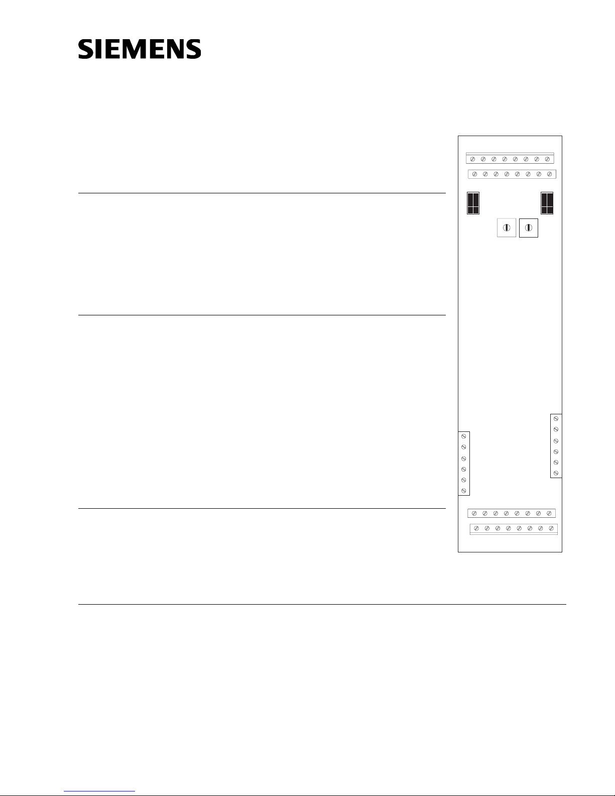
PRE-INSTALLATION Rotary Address Switches - Set the board address for
each SIM-16 using both of the ten-position rotary
switches located on the board (See Figure 1). Each of
these addresses must be a sub-address of the NIC-C
and must be the same as the addresses assigned in the
Zeus Programming Tool.
TB1
TB2
SIM-16
12345678
910111213141516
P3
5
5
6
6
4
4
7
7
3
3
8
8
2
2
9
9
1
1
0
0
TB3
P2
S1 S2
6
1
TB4
6
1
910111213141516
12345678
Figure 1
SIM-16 Supervised Input
Module
INSTALLATION A SIM-16 may be installed in a REMBOX. When using REMBOX 2 or 4, mount the
SIM-16 in one module space on a REMBOX2-MP, P/N 500-634211 or REMBOX4-MP,
P/N 500-634212 using the four screws provided. (Refer to REMBOX2-MP/REMBOX4MP Installation Instructions, P/N 315-034211.) Up to 4 SIM-16s will fit in a REMBOX2;
up to 8 SIM-16s will fit in a REMBOX4.
P/N 315-034060-3
Siemens Building Technologies
Fire Safety
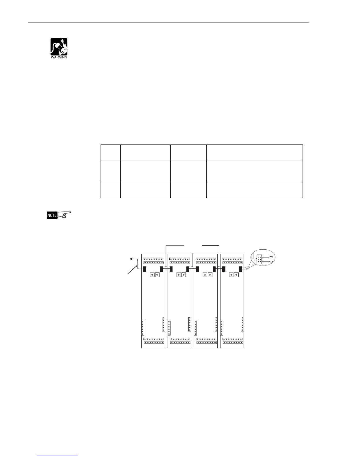
WIRING Refer to Figures 2-6.
Disconnect BATTERY and AC prior to working on equipment.
Each SIM-16 module is a node in the CAN bus.
The SIM-16 can be installed with or without an RNI. Connect the CAN bus
and 24V as shown in Figures 2 and 3.
Up to 99 CAN modules, in any combination, can be connected to the CAN
bus of each NIC-C.
Each SIM-16 module is shipped with one CCS cable.
Cable connections for SIM-16 modules are shown in the following table:
elbaCnoitpircseDrebmuNtraPnoitcennoC
SNOITCENNOCELBAC61-MIS
LCCgnoL-ELBAC-NAC
rotcudnoc-6,.ni03
412436-995.61-MIStsrifotINRno4PstcennoC
/MCFot61-MISmorfstcennocoslA
.)roodno(seludomBSC/MCS/MCL
SCCtrohS-ELBAC-NAC
rotcudnoc-6,.ni½5
935331-55561-MISotseludom61-MISstcennoC
worelgnisaniseludom61-MCOro
The CAN bus requires a 120S termination at each end of the loop. Refer to the NIC-C
Installation Instructions, P/N 315-033240 for details about CAN termination.
CABLE
MODEL
TO RNI, P4
CABLE
MODEL
# CCL
# CCS
5
6
4
7
3
8
2
9
1
0
P3
5
6
4
7
3
8
2
9
1
0
TB4
6
1
910111213141516
12345678
TB1
12345678
910111213141516
P2
S1 S2
TB3
6
1
TB2
TB1
12345678
910111213141516
P2
S1 S2
TB1
12345678
910111213141516
P3
P2
5
5
6
6
4
4
7
7
3
3
8
8
2
2
9
9
1
1
0
0
S1 S2
SIM-16 SIM-16 SIM-16 SIM-16
TB4
6
TB3
6
1
TB2
TB3
6
1
1
910111213141516
12345678
TB2
5
6
4
7
3
8
2
9
1
0
P3
5
6
4
7
3
8
2
9
1
0
TB4
6
1
910111213141516
12345678
TB1
12345678
910111213141516
P2
5
6
4
7
3
8
2
9
1
0
S1 S2
TB3
6
1
TB2
P3
CAN TERMINATOR,
5
6
4
7
3
8
2
9
1
0
P/N 110-134215
(SHIPPED WITH NIC-C)
TB4
6
1
910111213141516
12345678
Figure 2
SIM-16 CAN Bus Connections With An RNI
Siemens Building Technologies
Fire Safety
P/N 315-034060-32
 Loading...