

Siemens SIJECT15, SIJECT16 Operation Manual
SIJECT15/16
Operation Manual
Software Version 1
User Manual 06.2003 Edition
User Documentation

SIJECT 15/16 Document Structure
General Documentation:
SINUMERIK
Short
Guide for
Start-up
User Manual: Operator Manual
SINUMERIK
Operation
Manual
Technical Manual: Start-Up
SINUMERIK
Start-up


SIJECT 15/16
Operation Manual
Software Version 1
User Manual
Introduction
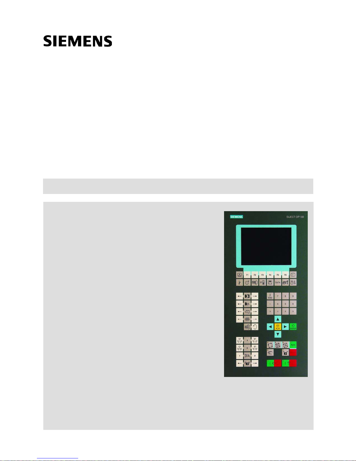
Operator panel keys
SIJECT OP15B Screen
1
2
3
Valid for
Control System Software Version
SIJECT 15/16 1.08
06.2003 Edition


SIJECT® Documentation
Key to editions
The editions listed below have been published prior to the current edition.
The column headed "Note" lists the amended sections, with reference to the previous edition.
Marking of edition in the "Note" column:
A .... New documentation.
Unchanged reprint with new order number
B ....
C .... Revised edition of new issue.
If any technical details presented on one of these pages have been changed with reference to
the previous edition, it is indicated by another edition number in the header of the respective
page.
Edition
12.2000
06.2001
07.2002
Order No.
6AT1931-5AB41-0KA0
6AT1931-5AB41-0KA0
6AT1931-5AB41-0KA1
Remark
A
C
A
06.2003
Tested Siemens quality for software and training t o
DIN ISO 9001, Reg. No. 2160-01
This publication was made with WinWord V 7
and Designer V 6.0
Passing on and reproduction of this document, and utili zation and disclosure of its
contents is not allowed unless specifically authorized.
Violations shall be cause for damage liability. All rights reserved, par ticularly in the
event a patent is issued or a utility model patent is registered.
© Siemens AG 2003. All Rights Reserved.
Order No.
Printed in People’s Republic of China
Other functions which are not described in this Documentation can possibly also
be performed on the control system. However, the customer is n ot entitled to
demand these functions when new equipment is supplied or servici ng is carried
out.
Although we have checked the contents of this publication f or agreement with the
hardware and software described, we do not accept liability for total agreement
since differences cannot be totally ruled out. The inf ormation in this publication is
checked at regular intervals and necessary correction includ ed in the next release.
Suggestions are welcome.
Subject to change without prior notice.
Siemens-Aktiengesellschaft.


Table of Content
1 Introduction .................................................................................................. 1-1
1.1 Operating panel layout ......................................................................... 1-2
1.2 Overview of screens............................................................................. 1-4
1.3 Working process of injection molding machine.................................... 1-6
2 Operator panel keys .................................................................................... 2-1
2.1 Liquid crystal display (LCD) ................................................................. 2-2
2.2 Soft keys............................................................................................... 2-3
2.3 Screen hot keys.................................................................................... 2-6
2.4 Manual Operating Keys........................................................................ 2-8
2.5 Number Keys...................................................................................... 2-11
2.6 Cursor Keys........................................................................................ 2-11
2.7 Operating mode keys ......................................................................... 2-12
2.8 Motor keys and Heater keys .............................................................. 2-15
3 SIJECT OP15B Screens ............................................................................. 3-1
3.1 Hot key Screens ................................................................................... 3-2
3.1.1 Information Screen 3-9
3.1.2 Monitoring screen 3-12
3.1.3 Alarm screen 3-14
3.1.4 Temperature screen 3-16
3.1.5 Timer screen 3-17
3.1.6 Counter screen 3-19
3.1.7 Function screen 3-20
3.1.8 Save/load screen 3-22
3.1.9 Data screen 3-24
3.1.10 Service screen 3-26
3.2 Manual operation screen.................................................................... 3-38
3.2.1 Mold open/close screen 3-38
3.2.2 Ejector screen 3-40
3.2.3 Carriage Screen 3-42
3.2.4 Injection screen 3-43
3.2.5 Charging screen 3-45
3.2.6 Core 1 screen 3-47
3.2.7 Core 2 screen 3-50
3.2.8 Air blow screen 3-52
3.2.9 Mold adjustment screen 3-53


1 Introduction
Contents
Section Heading Page
1.1 Operator panel layout 1-2
1.2 Overview of screens 1-4
1.3
Working process of injection
molding machine
1-6
SIJECT 15/16 Operation Manual June, 2003
1-1
Introduction
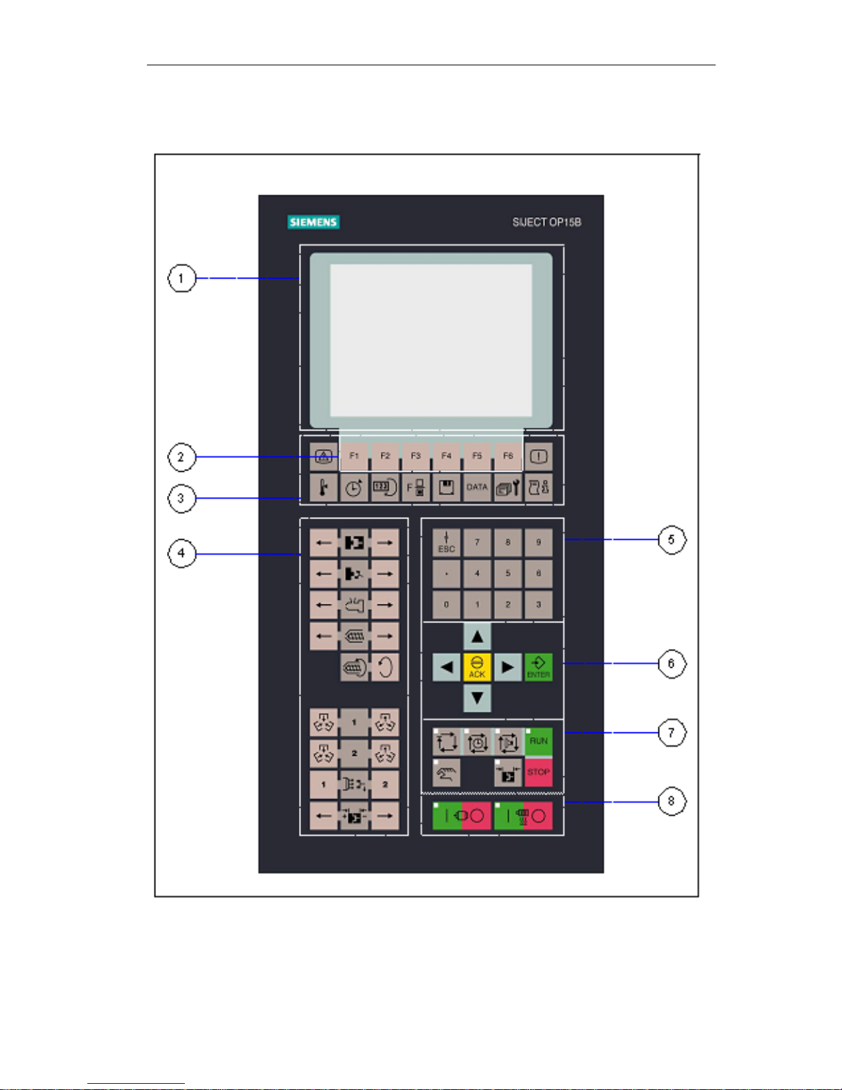
1.1 Operating panel layout
1-2
Fig. 1-1 Operator panel layout
SIJECT 15/16 Operation Manual June, 2003
Introduction
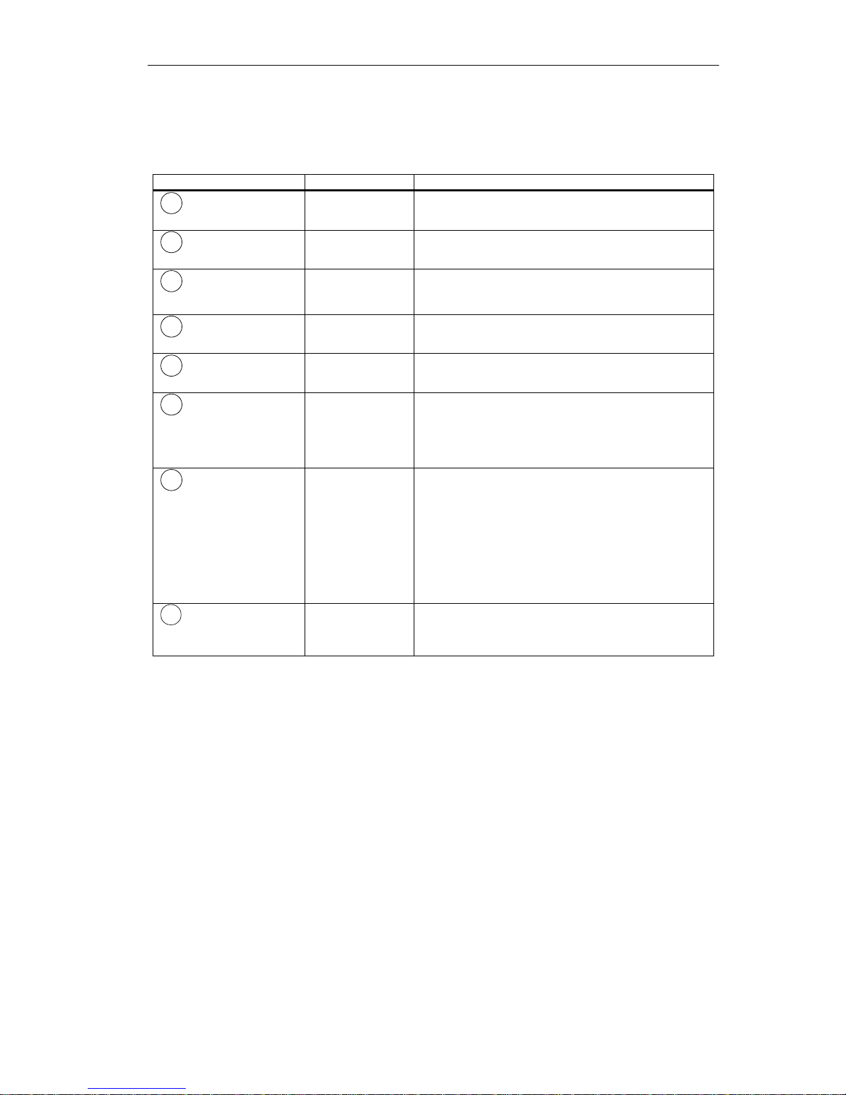
Description of softkey area
Explanation of the function of each softkey area is in Table 1-1.
Table 1-1 Description of softkey area
Operating area Key numbers Meaning
1
Liquid crystal display
2
Soft keys
3
Screen hot keys
4
Manual operating keys
5
Number keys
5
Cursor keys
7
Operating mode keys
8
Motor keys and heater
keys
-
5 keys
10 keys
26 keys
12 keys
6 keys
7 keys
4 keys
Display different control screens.
Call selected pictures from different screens.
Press each key and corresponding screen will be
displayed. Parameters setting, production
monitoring and data saving can be executed.
Call the parameter-setting screen with the key,
then control the machine movement manually.
Input number parameter. Create recipe data.
Move the cursor to the required position with
“Cursor key”, then press ”Enter” key to confirm
the setting.
Or, when screen displays the message “press
ACK key”, press “ACK” key to confirm.
Select machine mode with “Mode key”. When in
Semi Auto/Auto mode, press Run/Stop key to
start/stop the Semi Auto/Auto mode cycle.
Or, use “Manual Mode” key to select manual
mode, then you can press manual control key for
manual movement.
Or, press “Mode adjustment key” to select mold
adjustment mode, then you can do manual or
auto mold adjustment.
Control the motor start/stop, and heater on/off.
SIJECT 15/16 Operation Manual
1-3
Introduction
o
)
A
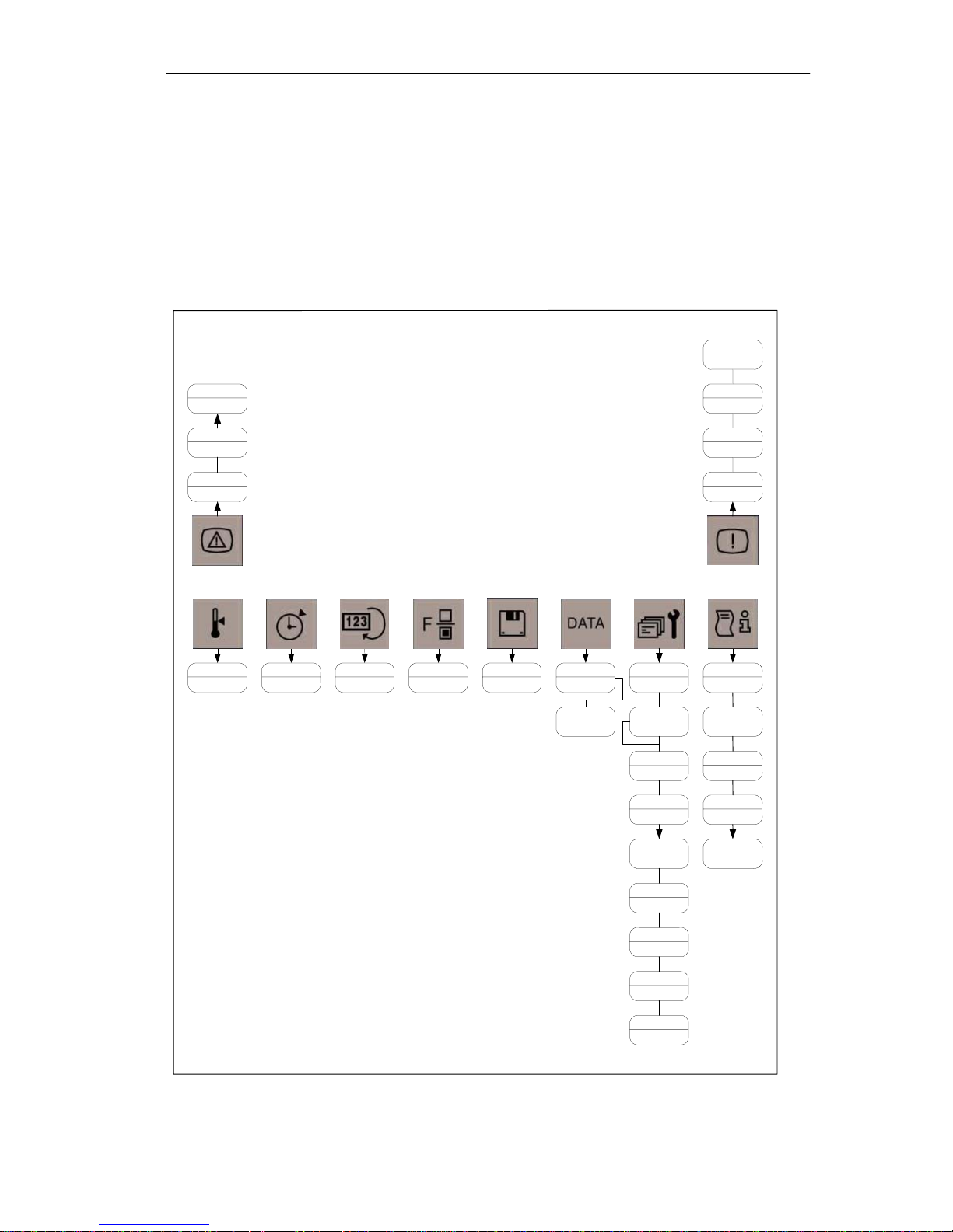
1.2 Overview of screens
Hot key screen
structure Service screen is designed in multistage structure, It is oriented to the
All hot key screens are listed in Table 1-2 for reference.
Table 1-2 Hot key screen structure
These screens are configured in different nested level. For instance, the
OEM-customer. Therefor it comprises the most important function
parameters for OEMs. Altogether nine different screens can be
displayed.
Screen 1.3
Manual lube
Screen 2
larm(con'd)
Screen 1.1
Event
Screen 1
Alarm
Screen 1
Temperature
Screen 1
Timer
Screen 1
Counter
Screen 1
Function
Screen 1
Load/save
Screen 1
Data
Screen 2
Data (con'd
Screen 1
Service
Screen 1.1
Password
Screen 1.2
Load/save
Screen 1.3
Set prop.valve
Screen 1.2
Purge
Screen 1.1
Event
Screen 1
Monitori ng
Screen 1
Version inf
Screen 1.1
OEM
Screen 1.2
DI
Screen 1.3
DO
1-4
Screen 2
Linear scale
Screen 2.1
Pump
Screen 2.2
Lubrication
Screen 2.3
Set function
Screen 2.4
Set ramp
Screen 2
PLC/CI Info
SIJECT 15/16 Operation Manual June, 2003
Introduction
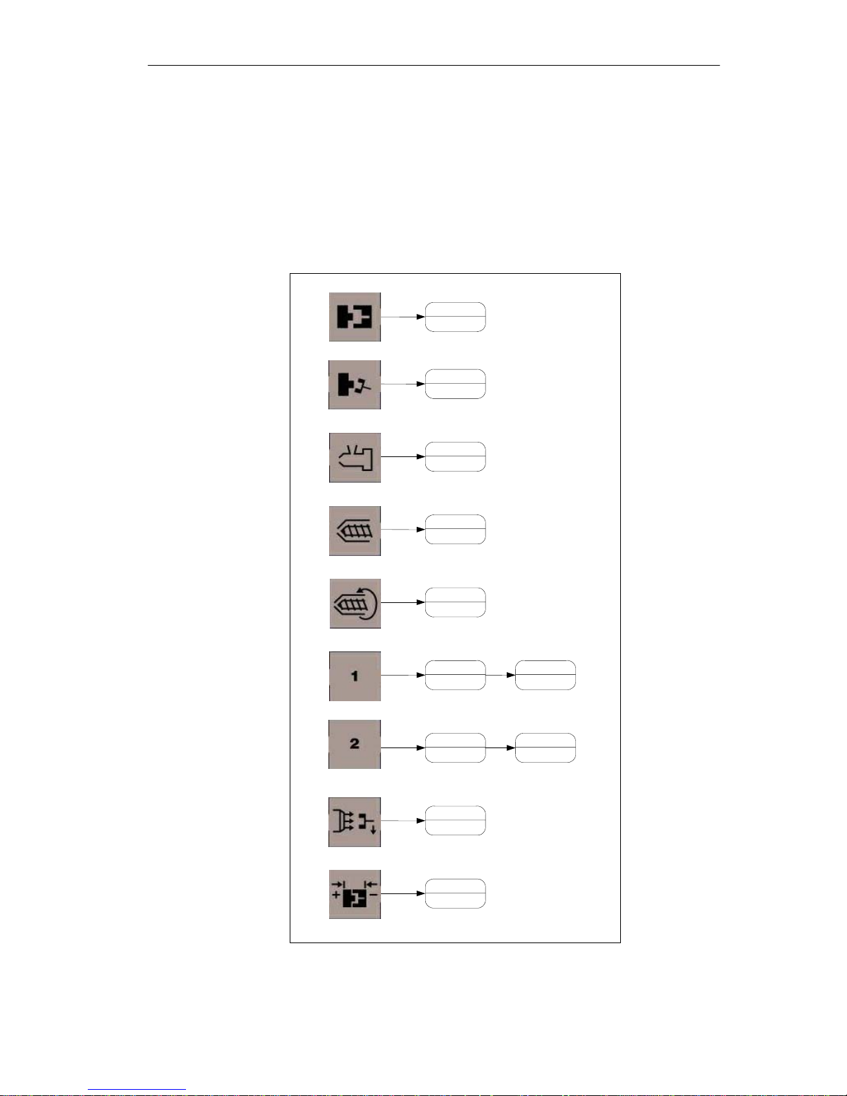
A
Screen structure of
manual operating keys
The screen structure here is relative simple in comparison with hot key
screen structure. It has only one level, and only the screens of core 1
in/out and core2 in/out have the 2
function.
The parameters like position, press, flow, delay, time, counter and mode
selection can be set in these screens.
Table 1-3 Screen structure of manual operating keys
Screen 1
Mld Clo/Opn
Screen 1
Eject
Screen 1
Carriage
nd
level, that is, they are used for core 3
Screen 1
Injection
Screen 1
Charging
Screen 1
Core 1
Screen 1
Core 2
Screen 1
ir blow
Screen 1
Mold adjust
Screen 2
Core 3
Screen 2
Core 3
SIJECT 15/16 Operation Manual
1-5
Introduction
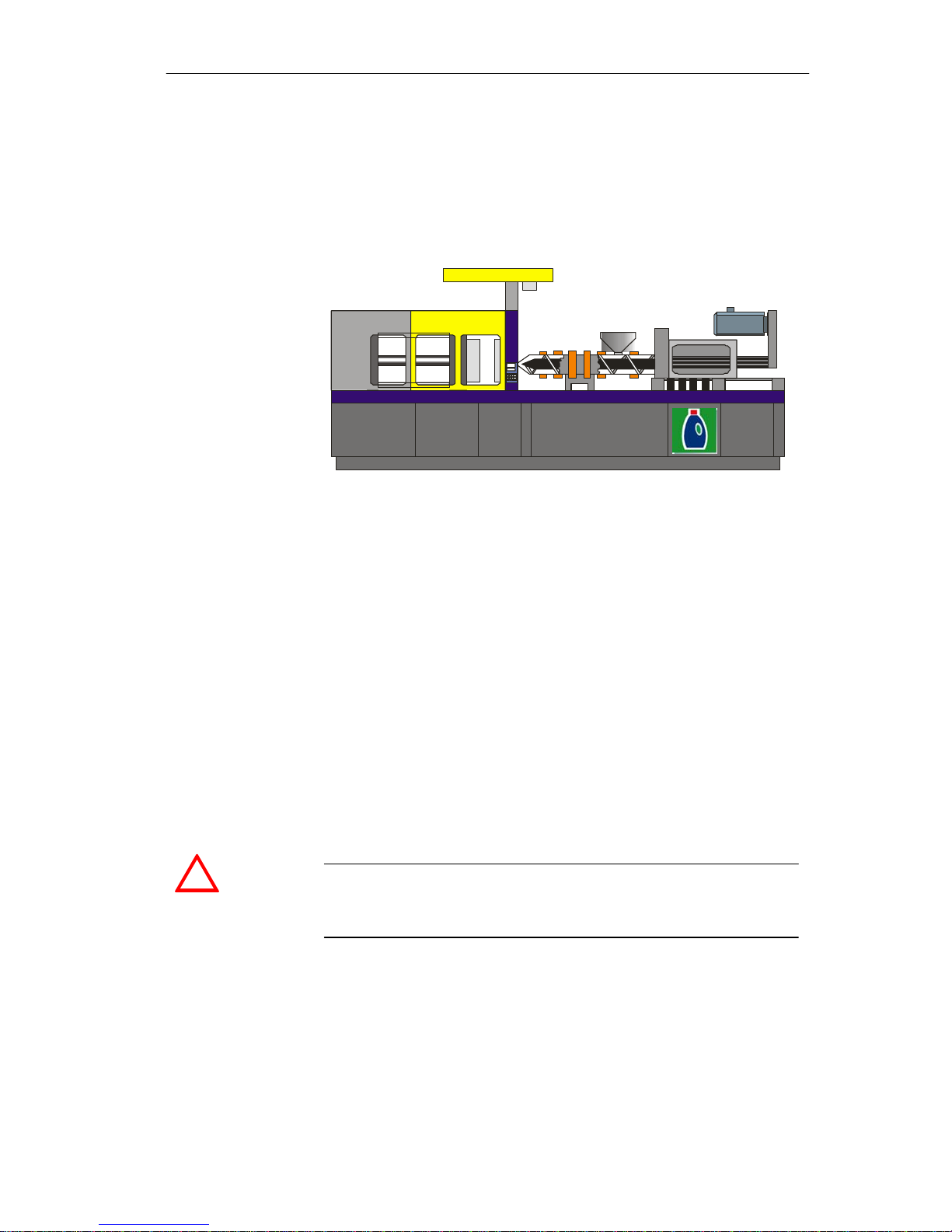
Working process of injection molding machine
General The most important components in the injection molding machine are:
— Injection unit
Mold close unit
—
— Electrical and hydraulic control
Fig. 1-2 Injection molding machine
SIJECT 15/16 Siject 15/16 is a compact control system. It can be widely used to control
injection molding machine from low end to middle and high end
customer. It is a series product and consists of different versions, i.e.
SIJECT 15
international version.
+
, SIJECT 16, SIJECT 16 international and SIJECT 16DP
Please see the manufacturer documentation “SIJECT 15/16 Start-up”
for detailed information.
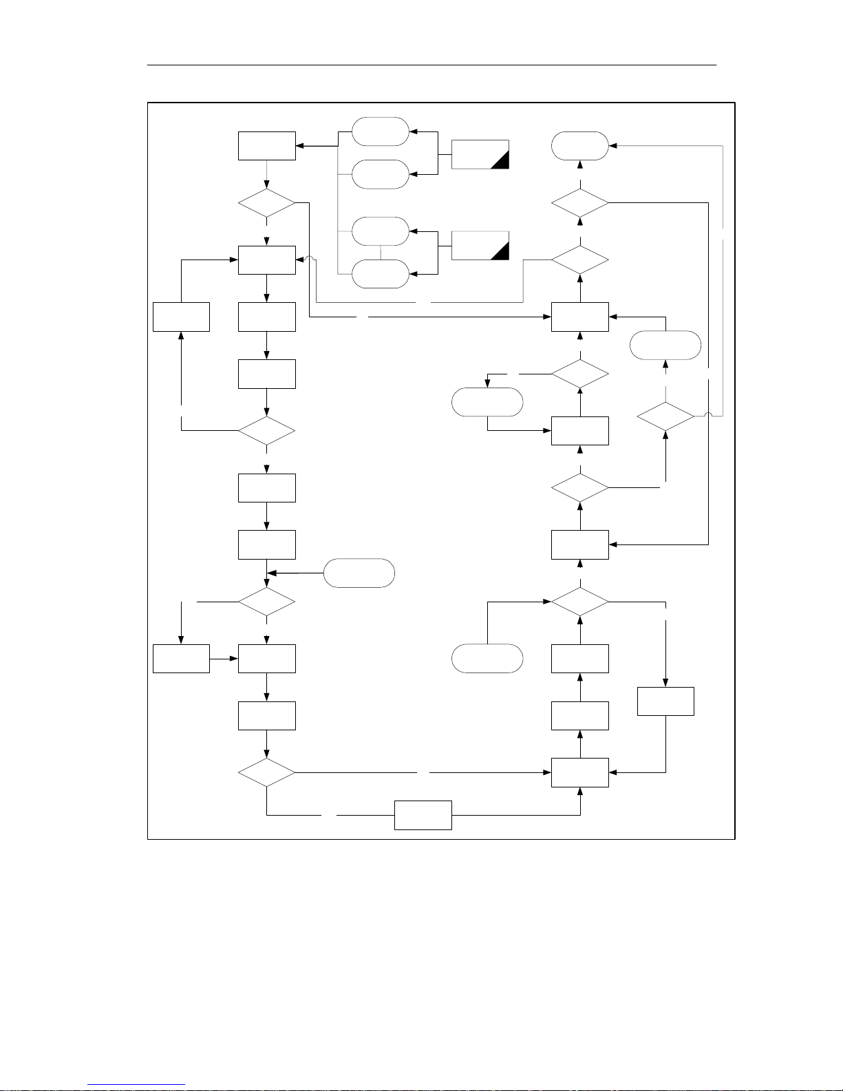
Control process The configuration of individual injection molding machine can be
different, but the working process should be implemented in a similar
way. Thus we describe it roughly in the following diagram.
It is provided in the diagram that the Core-in acts before Mold Close Start
or during Mold Close Process, the Core-out acts before Mold Open Start
or during Mold Open Process.
!
Caution
Other functions not described in the following diagram might be executed
in the control system. It is only available for reference.
1-6
SIJECT 15/16 Operation Manual June, 2003
Introduction
A
Time-full auto
Close mold
Cycle start
Ejector
retract end?
Yes
Core 1 in
Core 2 in
Sensor-full
auto
Safety door
close
Cycle key
start
No
Full auto
Semi auto
Yes
Cycle end
Yes
Counter
arrive
No
Ejector
auto-
retract?
Ejector retract
Yes
No
Yes
Carriage
retract
Core3 in
Mold clo se
end?
Yes
Carriage
advance
Injection/
holding
Back
feeding?
No
Charging
Suck back
Start cooling time
Ejector shake time
ir blow
Yes
No
Shake
times
arrive?
Ejector shake
Yes
Ejector
shake?
Ejector
advance
Yes
Mold open
end?
Core 1 out
Core 2 out
Stay time
No
Ejector
stay?
No
No
Open mold
No
Front
feeding?
Fig. 1-3 Flow chart for one cycle in injection molding machine
SIJECT 15/16 Operation Manual
Yes
No
Carriage
retract
Core 3 out
1-7


2 Operator panel keys
Contents
Section Heading Page
2.1 Liquid crystal display 2-2
2.2 Soft keys 2-3
2.3 Screen hot keys 2-6
2.4 Manual operating keys 2-8
2.5 Number keys 2-11
2.6 Cursor keys 2-11
2.7 Operating mode keys 2-12
2.8 Motor keys and heater keys 2-14
SIJECT 15/16 Operator manual June, 2003
2-1

Operator panel keys
2.1 Liquid crystal display (LCD)
General The LCD display with CCFL back-light has a good performance to
display:
Alarms
—
— Recipe data
— Customer specific picture
— Operation status
Performance The LCD has the following characteristics:
— 320x240 pixel
5.7” Chinese/English languages
—
— the brightness can be adjusted manually
2-2
SIJECT 15/16 Operation Manual June, 2003
Operator panel keys
2.2 Soft keys
General Users can press softkey to complete different operation as well as to
enter other screens.
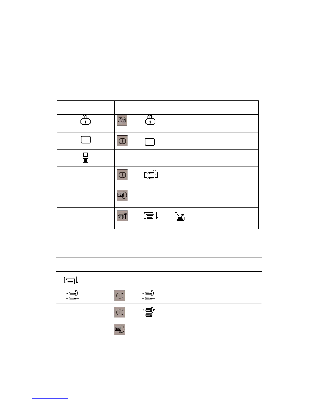
Softkey F1:
1
Softkey F1
“ ” ——》 :OEM( Original Equipment Manufacturer )
Operation path and function
specific picture
i
“
“ ”
“Purge start”
“Injection reset”
Manual
“
Lubrication”
Softkey F2:
Softkey F2 Operation path and function
“ ”
”
——》
i
:Event information
Selection key
——》
”Purge start”: start up the purge
——》
function.
——》”Injection reset”: execute reset fuction of injection
counting.
——》 ——》 ——》”Manual lubrication”:
lubricate manually.
Page down
“
”
“Purge stop”
“Product reset”
1
Functions can be executed, which is also applicable for soft keys in following tables.
SIJECT 15/16 Operation Manual
——》
——》
purge key
:
”Purge stop”: stop purge function.
——》
——》”Product reset”: execute product reset function.
2-3
Operator panel keys
Softkey F2
“PLC version”
“Force output”
“ ”
Softkey F3:
Softkey F3 Operation path and function
“Manual lubrication”
“ ”
——》
——》
——》
——》
——》
Operation path and function
”PLC version”: display PLC version of
——》
MMC card.
”Manual lubrication”: lubricate manually
”Force output”: force output.
——》
——》
Digit input。
:
Pump combination
:
“ ”
“ ”
“ + ”
“ ”
“ ”
“ ”
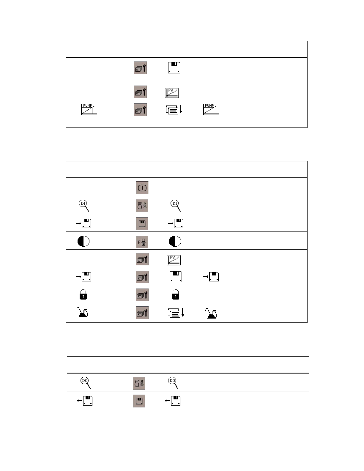
Softkey F4:
“ ”
Softkey F4 Operation path and function
——》
——》
——》
——》
——》
——》
——》
save mold parameters into MMC card or CI
:
increase screen brightness
:
——》+ :
——》 :
set the password
:
——》
digit output
:
increase limit value
save program into MMC card
set manual lubrication
:
“ ”
2-4
SIJECT 15/16 Operation Manual June, 2003
——》
load mold parameters from MMC card or CI
:
Operator panel keys
Softkey F4
“ ”
“ - ”
“ ” ——》 ——》 :load program from MMC card。
“ ”
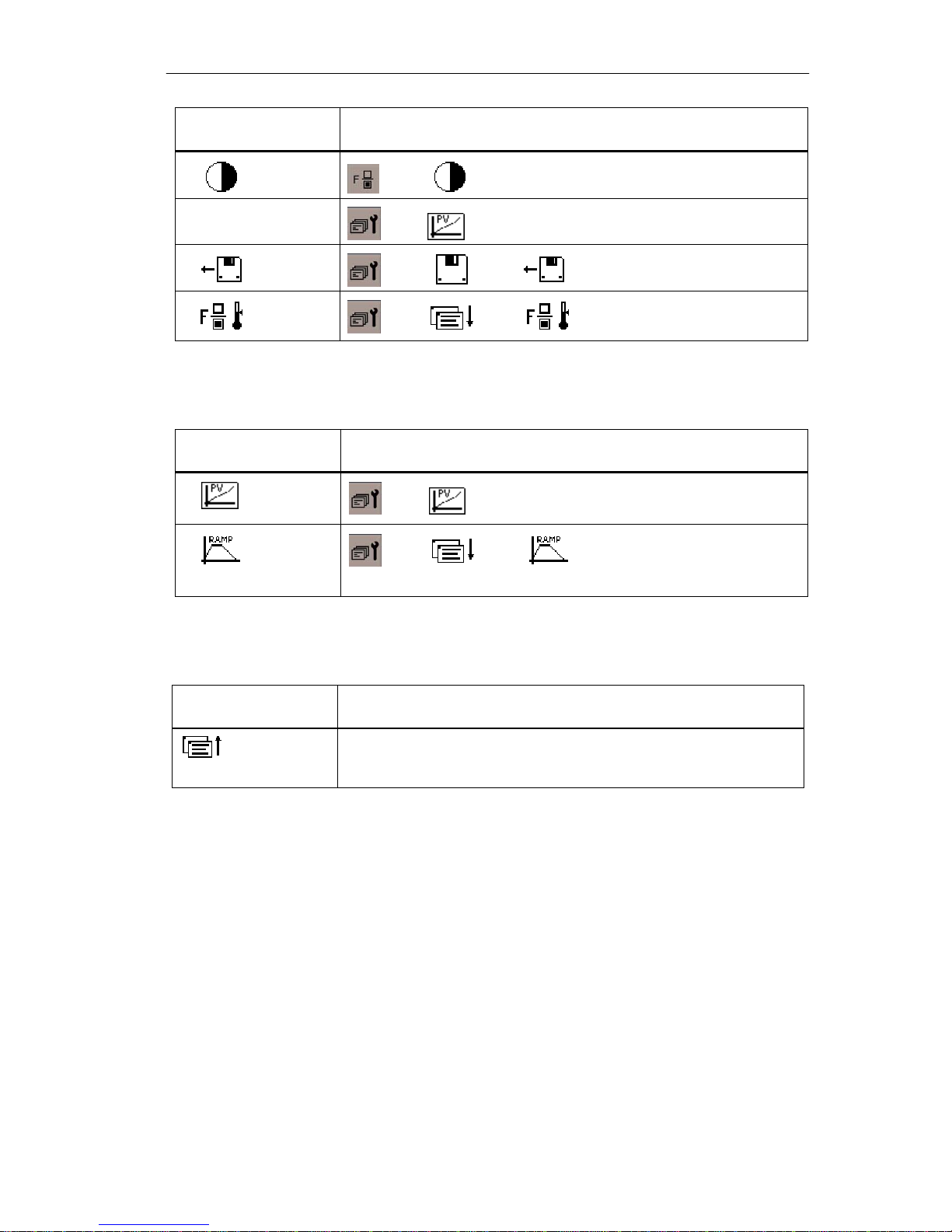
Softkey F5:
“
“ ”
Softkey F5 Operation path and function
”
——》
——》
——》
——》
——》
Operation path and function
decrease screen brightness
:
——》- :
——》
proportional valve start-up
:
——》
reduce limit value
temperature setting
:
ramp data setting
:
Softkey F6:
Softkey F6
Page up
Operation path and function
SIJECT 15/16 Operation Manual
2-5
Operator panel keys
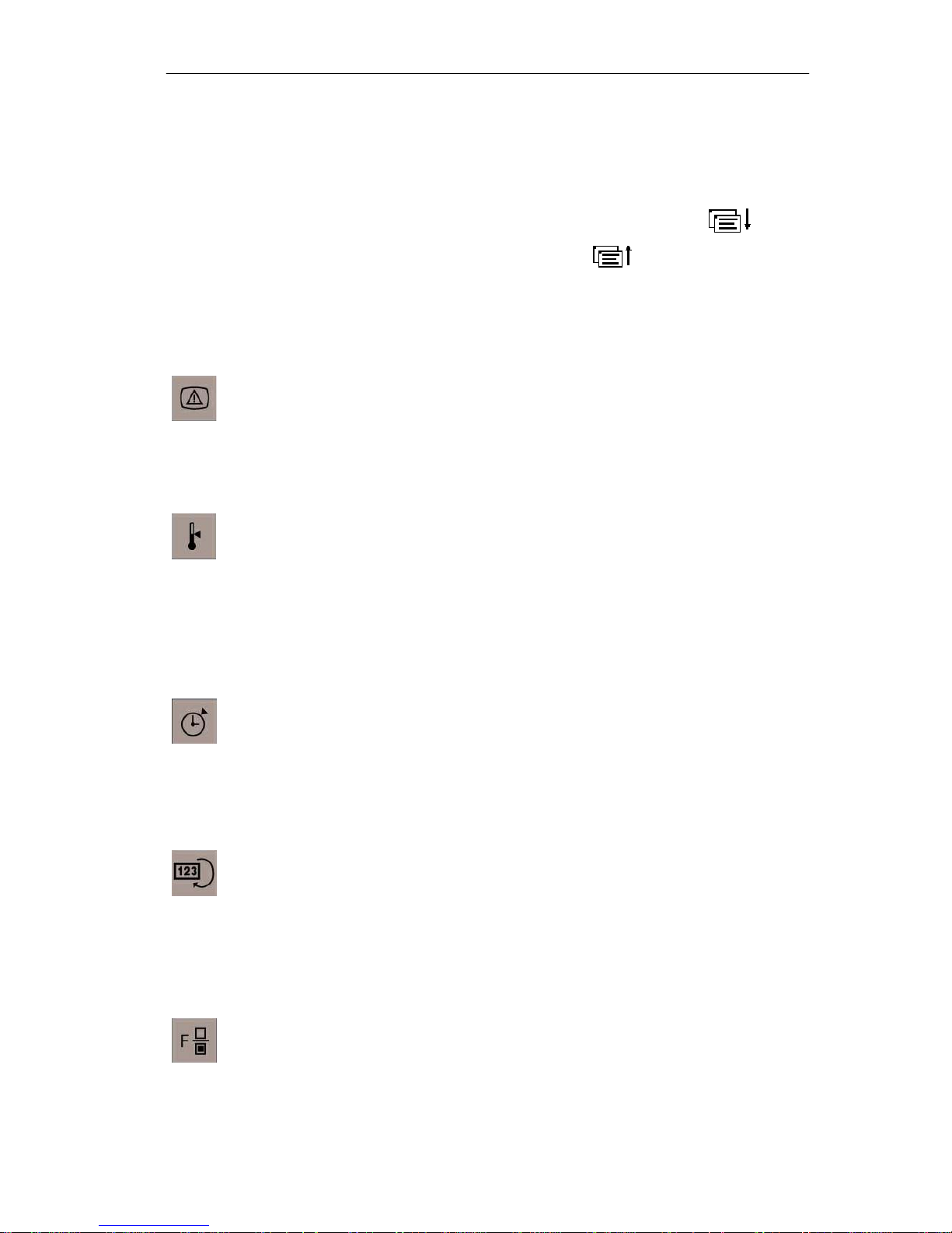
2.3 Screen hot keys
General Press each key and corresponding screen will be displayed. If the screen
has more than one layer, use the soft keys of page down
the next layer. Press the page up key
previous screen.
Alarm key
Press Alarm key to enter Alarm screen, and the current alarm will be
displayed on this screen. Press F1 key to enter the event record screen,
and you can check the record of all events.
Temperature key
at right to go back to the
to go to
You can also choose the control mode of nozzle (open loop/close loop).
Timer key
Counter key
Press this key to enter Counter screen. You can set the quantity of
Function key
Press Function key to enter
Press this key to enter Temperature screen where the set value of each
temperature channel can be input, and the actual value of temperature
channel can be displayed as well. In addition, you can choose the “heat
holding” function, and you can set the tolerance of temperature control.
Press this key to enter Timer screen. Every time duration can be set,
such as cycle time, cooling time, mold open/close time, as well as every
delay time and monitoring time.
products and the products of each mold. Also the current product
quantity, number of injection and products quantity after machine power
on can be displayed.
Function screen
language (Chinese/English), selection of robot and back light functions
can be set.
. The screen brightness,
2-6
SIJECT 15/16 Operation Manual June, 2003

Operator panel keys
Load/save key
Press this key to enter
saved into CI/MMC, and saved mold recipe data can be loaded from
CI/MMC.
Load/save screen
. Mold recipe data can be
Data key
Press this key to enter Data screen. You can review the production data
of last 10 injection cycles, including the position and time of each activity,
such as injection number, the position of mold open end point, injection
start point, injection end point, pressure hold end point, charging end
point and ejector end point, and the time for mold hold, mold lock,
injection, cycle and charging.
Service key
Information key
Press this key to enter
and functions here. Nine service screens are provided, including function
selection, linear scale setting, password setting, load/save setting,
proportional valve setting, pump setting, lubrication setting, temperature
setting and ramp setting.
When OEM has finished the start-up of injection molding machine, these
parameters will normally be protected by Password 2 by OEM.
Service screen
. OEM can set the factory data
Users can also check the operating status of each digit input/output.
Press Information key to enter Information screen where the version
message of OP, CI and PLC program can be read. Then press the
softkey F2, and continue to display the PLC status and OP
communication status.
Monitoring key
Press Monitoring key to enter Monitoring screen, which is the main
screen of system. The current machine running status are displayed,
including the positions of mold, screw, ejector; rotation speed of screw;
production quantity; power on time; cycle time and current mold number.
Additionally, the purge and lubrication can also be operated.
SIJECT 15/16 Operation Manual
2-7
Operator panel keys
2.4 Manual Operating Keys
General All the manual keys
the Manual mode and Mold adjustment is running.
Mold key
Press the middle Mold key to enter Mold screen.
Input corresponding parameter (Position, pressure, flow and protecting
time) for each step.
Mold will open continuously if you keep pressing the left key.
Mold will close continuously if you keep pressing the right key.
Mold close/open keys can be operated in combination with core in/out
keys, for example, “Core in” can be done during, before or after mold
close, or “Core out” during, before or after mold open.
Ejector key
Press the middle Ejector key to enter
Now you can input corresponding parameter (Position, pressure, flow
and counter) for ejector advance and retract, and set counter and
ejector mode.
Ejector will retract continuously if you keep pressing the left key.
Ejector will advance continuously if you keep pressing the right key.
Repeat above-mentioned two steps to carry out multiple ejection.
Carriage key
Press the middle Carriage key to enter Carriage screen.
Now you can input corresponding parameter (pressure, flow and
injection time) for carriage advance and retract.
Carriage will advance continuously if you keep pressing the left key.
Carriage will retract continuously if you keep pressing the right key.
and described below can function only after
Ejector screen
.
2-8
SIJECT 15/16 Operation Manual June, 2003
Operator panel keys
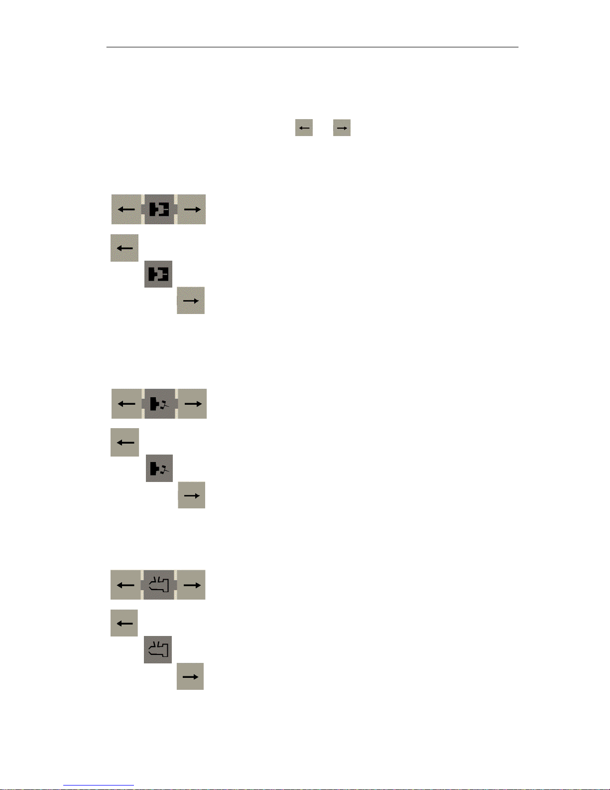
Injection key
Press the middle Injection key to enter Injection screen.
Input corresponding parameter (pressure, position, flow and total
injection time) for injection.
Machine will inject once if you press the left key. Keep pressing the left
key, the machine will come into pressure holding status automatically
after injection is finished.
Machine will suck back, i.e., screw retract, if you keep pressing the right
key.
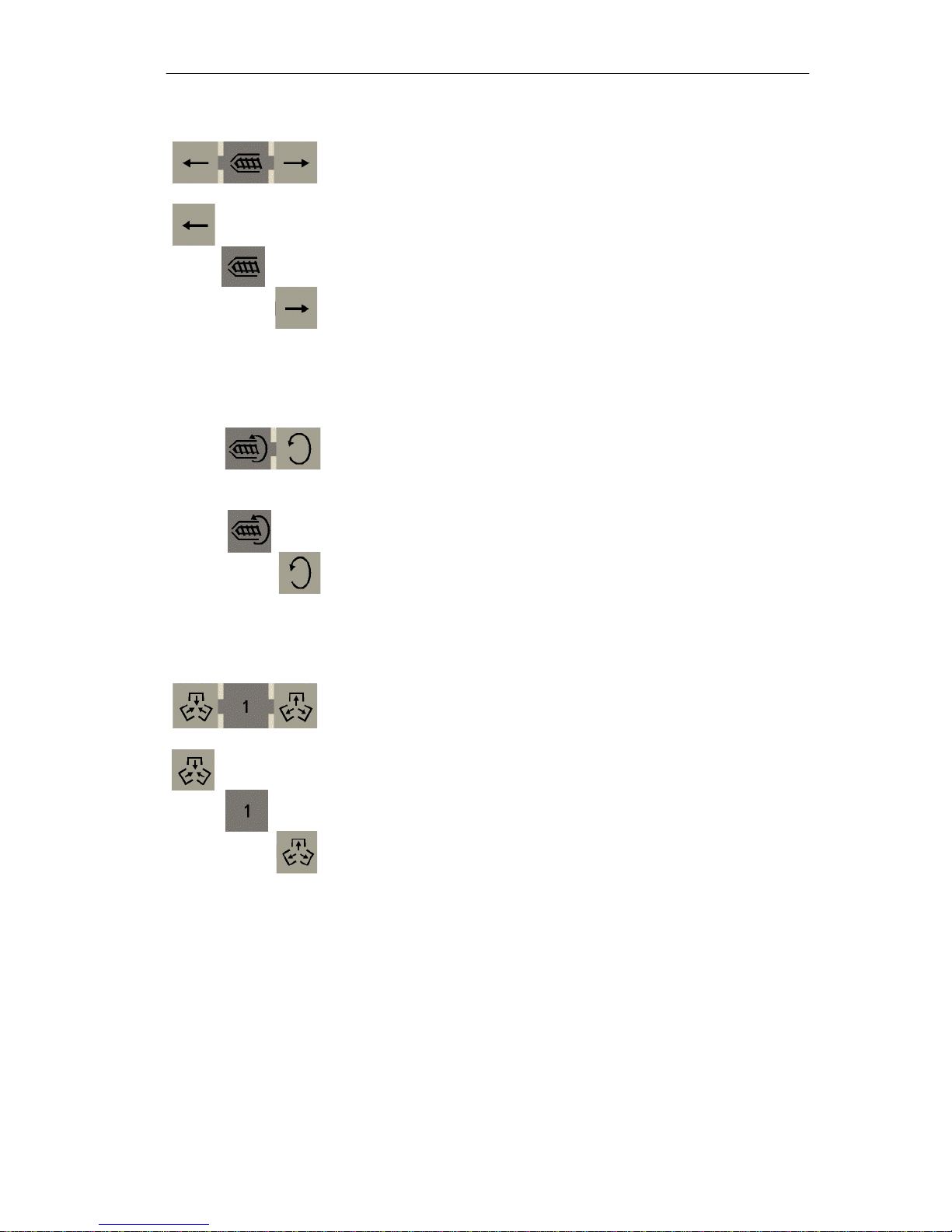
Charge key
Press the middle Charge key to enter Charge screen.
Input corresponding parameter (Position, pressure and flow) for
charging.
Screw will be charging if you keep pressing the right key.
Core 1 key
Press the middle Core 1 key to enter
Input corresponding parameter for core 1, such as position, pressure,
flow, time and counting.
Keep pressing the left key to let core 1 in.
Keep pressing the right key to let core 1 out.
Core 1 screen
.
SIJECT 15/16 Operation Manual
2-9
Operator panel keys
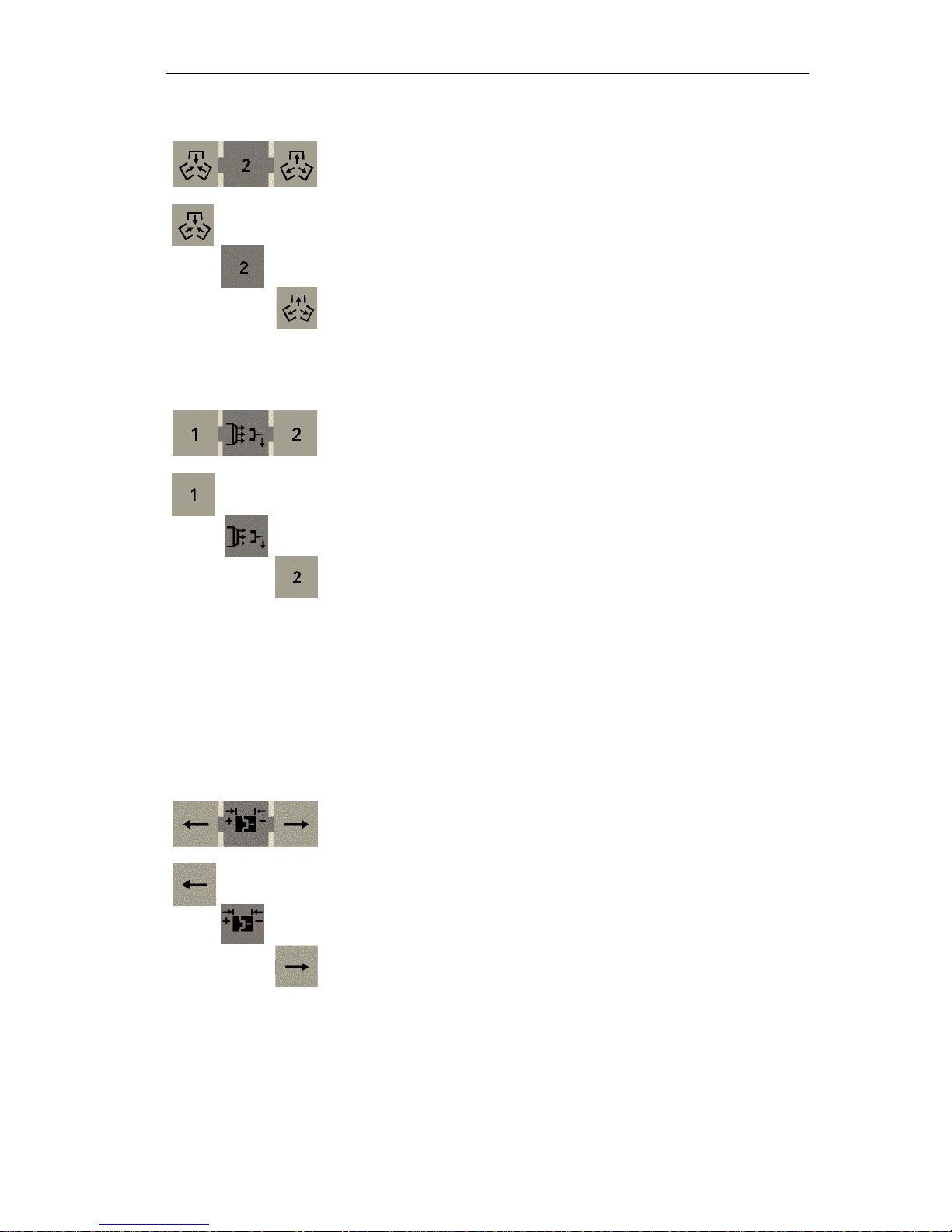
Core 2 key
Air-blow key
Press the middle Core 2 key to enter Core 2 screen.
Input corresponding parameter for core 2, such as position, pressure,
flow, time and counting.
Keep pressing the left key to let core 2 in.
Keep pressing the right key to let core 2 out.
Press the middle Air-blow key to enter
Input corresponding parameter (position and time) for Air-blow 1 and Airblow 2.
Air-blow 1 will work if you press the left key.
Air-blow screen
.
Air-blow 2 will work if you press the right key.
Press the Air-blow key again to enter Core 3 screen.
Input corresponding parameter (pressure, position, flow and time) for
core 3 in/out.
Keep pressing the left key to let core 3 in.
Keep pressing the right key to let core 3 out.
Mold adjustment key
Press the middle Mold adjustment key to enter Mold adjustment
screen.
Input pressure and flow for mold adjustment. There are two ways to
adjust mold. When manual mold adjustment is selected, you can set
pulse here. If auto mode is selected, you can set the time of adjusting.
Mold adjustment retracts if you keep pressing the left key.
Mold adjustment advances if you keep pressing the right key.
2-10
SIJECT 15/16 Operation Manual June, 2003
 Loading...