

Siemens SIPROTEC 5, Siemens 7KE85 User Manual

Preface
Open Source Software
Table of Contents
SIPROTEC 5
Fault Recorder
7KE85
V7.50 and higher
Manual
Introduction
Basic Structure of the Function
System Functions
Applications
Power-System Data
Function-Group Types
Fault Recorder
Supervision Functions
Measured and Energy Values
1
2
3
4
5
6
7
8
9
C53000-G5040-C018-5
Functional Tests
Technical Data
Appendix
Glossary
Index
10
11
A

i
i
NOTE
For your own safety, observe the warnings and safety instructions contained in this document, if available.
Disclaimer of Liability
This document has been subjected to rigorous technical
review before being published. It is revised at regular intervals, and any modifications and amendments are included
in the subsequent issues. The content of this document has
been compiled for information purposes only. Although
Siemens AG has made best efforts to keep the document as
precise and up-to-date as possible, Siemens AG shall not
assume any liability for defects and damage which result
through use of the information contained herein.
This content does not form part of a contract or of business
relations; nor does it change these. All obligations of
Siemens AG are stated in the relevant contractual agreements.
Siemens AG reserves the right to revise this document from
time to time.
Document version: C53000-G5040-C018-5.03
Edition: 11.2017
Version of the product described: V7.50 and higher
Copyright
Copyright © Siemens AG 2017. All rights reserved.
The disclosure, duplication, distribution and editing of this
document, or utilization and communication of the content
are not permitted, unless authorized in writing. All rights,
including rights created by patent grant or registration of a
utility model or a design, are reserved.
Registered Trademarks
SIPROTEC®, DIGSI®, SIGUARD®, SIMEAS®, and SICAM® are
registered trademarks of Siemens AG. Any unauthorized
use is illegal. All other designations in this document can
be trademarks whose use by third parties for their own
purposes can infringe the rights of the owner.
Preface
Purpose of the Manual
This manual describes the functions of the fault recorder 7KE85.
Target Audience
System configurers, commissioning engineers, and persons entrusted with the setting, testing and maintenance of fault recorder equipment, and operational crew in electrical installations and power plants.
Scope
This manual applies to the SIPROTEC 5 device family.
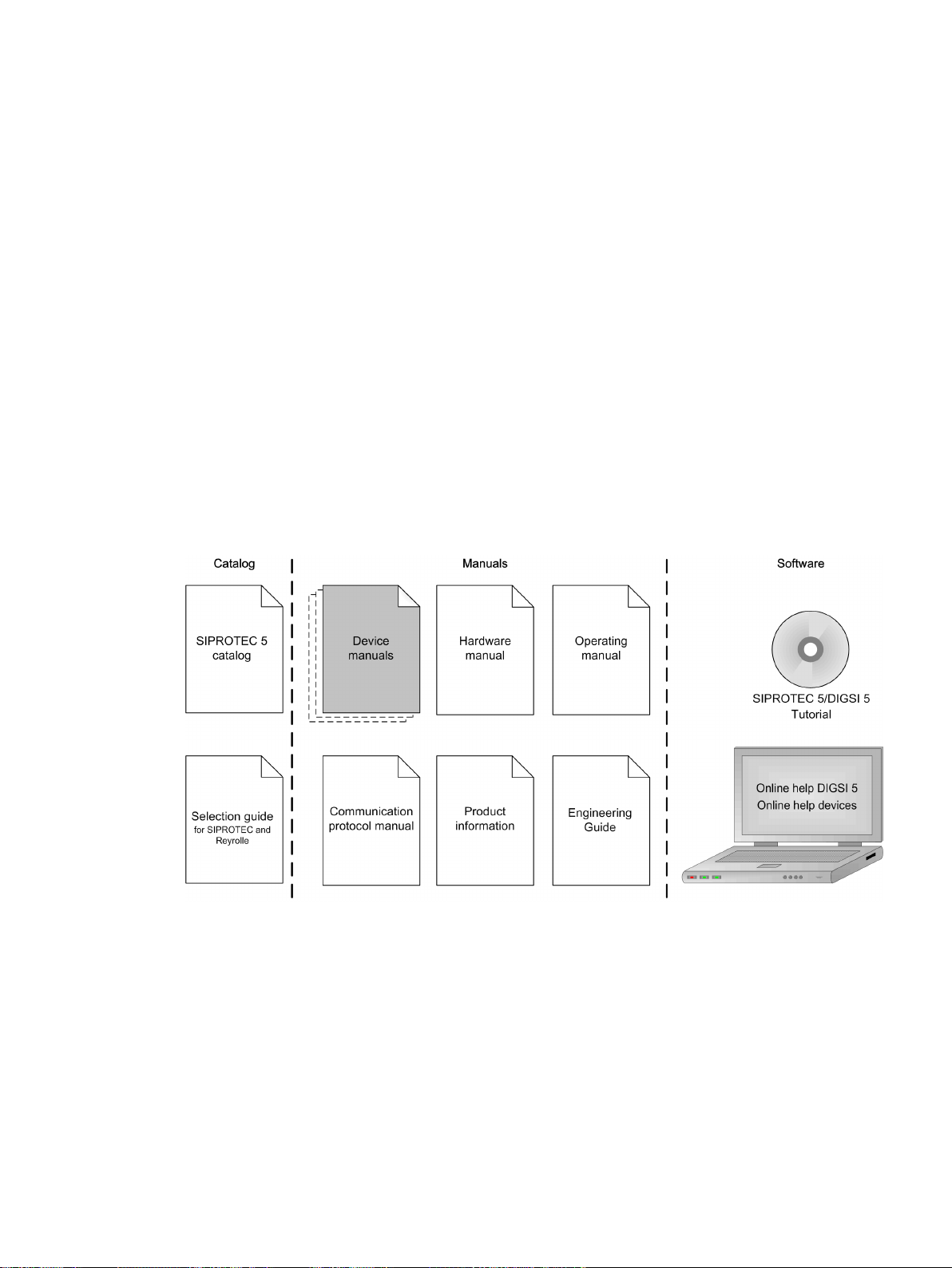
Further Documentation
[dwprefdm-221012-01.tif, 3, en_US]
Device manuals
•
Each Device manual describes the functions and applications of a specific SIPROTEC 5 device. The printed
manual and the online help for the device have the same informational structure.
Hardware manual
•
The Hardware manual describes the hardware building blocks and device combinations of the SIPROTEC 5
device family.
Operating manual
•
The Operating manual describes the basic principles and procedures for operating and assembling the
devices of the SIPROTEC 5 range.
SIPROTEC 5, Fault Recorder, Manual
C53000-G5040-C018-5, Edition 11.2017
3

IND. CONT. EQ.
69CA
Preface
Communication protocol manual
•
The Communication protocol manual contains a description of the protocols for communication within
the SIPROTEC 5 device family and to higher-level network control centers.
Product information
•
The Product information includes general information about device installation, technical data, limiting
values for input and output modules, and conditions when preparing for operation. This document is
provided with each SIPROTEC 5 device.
Engineering Guide
•
The Engineering Guide describes the essential steps when engineering with DIGSI 5. In addition, the Engineering Guide shows you how to load a planned configuration to a SIPROTEC 5 device and update the
functionality of the SIPROTEC 5 device.
DIGSI 5 online help
•
The DIGSI 5 online help contains a help package for DIGSI 5 and CFC.
The help package for DIGSI 5 includes a description of the basic operation of software, the DIGSI princi-
ples and editors. The help package for CFC includes an introduction to CFC programming, basic examples
of working with CFC, and a reference chapter with all the CFC blocks available for the SIPROTEC 5 range.
SIPROTEC 5/DIGSI 5 Tutorial
•
The tutorial on the DVD contains brief information about important product features, more detailed information about the individual technical areas, as well as operating sequences with tasks based on practical
operation and a brief explanation.
SIPROTEC 5 catalog
•
The SIPROTEC 5 catalog describes the system features and the devices of SIPROTEC 5.
Selection guide for SIPROTEC and Reyrolle
•
The selection guide offers an overview of the device series of the Siemens protection devices, and a
device selection table.
Indication of Conformity
Other Standards
IEEE Std C 37.90
The technical data of the product is approved in accordance with UL.
For more information about the UL database, see certified.ul.com
Select Online Certifications Directory and enter E194016 as UL File Number.
This product complies with the directive of the Council of the European Communities
on harmonization of the laws of the Member States relating to electromagnetic
compatibility (EMC Directive 2014/30/EU) and concerning electrical equipment for use
within specified voltage limits (Low Voltage Directive 2014/35/EU).
This conformity has been proved by tests performed according to the Council Directive
in accordance with the product standard EN 60255-26 (for EMC directive) and with the
product standard EN 60255-27 (for Low Voltage Directive) by Siemens AG.
The device is designed and manufactured for application in an industrial environment.
The product conforms with the international standards of IEC 60255 and the German
standard VDE 0435.
[ul_listed_c_us, 1, --_--]
4 SIPROTEC 5, Fault Recorder, Manual
C53000-G5040-C018-5, Edition 11.2017
Additional Support
!
!
!
For questions about the system, please contact your Siemens sales partner.
Support
Our Customer Support Center provides a 24-hour service.
Phone: +49 (180) 524-7000
Fax: +49 (180) 524-2471
E-Mail: support.energy@siemens.com
Training Courses
Inquiries regarding individual training courses should be addressed to our Training Center:
Siemens AG
Siemens Power Academy TD
Humboldtstraße 59
90459 Nürnberg
Germany
Phone: +49 (911) 433-7415
Fax: +49 (911) 433-7929
E-Mail: poweracademy@siemens.com
Internet: www.siemens.com/poweracademy
Preface
Notes on Safety
This document is not a complete index of all safety measures required for operation of the equipment (module
or device). However, it comprises important information that must be followed for personal safety, as well as
to avoid material damage. Information is highlighted and illustrated as follows according to the degree of
danger:
DANGER
DANGER means that death or severe injury will result if the measures specified are not taken.
²
WARNING
WARNING means that death or severe injury may result if the measures specified are not taken.
²
CAUTION
Comply with all instructions, in order to avoid death or severe injuries.
Comply with all instructions, in order to avoid death or severe injuries.
CAUTION means that medium-severe or slight injuries can occur if the specified measures are not taken.
Comply with all instructions, in order to avoid moderate or minor injuries.
²
SIPROTEC 5, Fault Recorder, Manual 5
C53000-G5040-C018-5, Edition 11.2017

i
i
Preface
NOTICE
NOTICE means that property damage can result if the measures specified are not taken.
Comply with all instructions, in order to avoid property damage.
²
NOTE
Important information about the product, product handling or a certain section of the documentation
which must be given particular attention.
Qualified Electrical Engineering Personnel
Only qualified electrical engineering personnel may commission and operate the equipment (module, device)
described in this document. Qualified electrical engineering personnel in the sense of this manual are people
who can demonstrate technical qualifications as electrical technicians. These persons may commission,
isolate, ground and label devices, systems and circuits according to the standards of safety engineering.
Proper Use
The equipment (device, module) may be used only for such applications as set out in the catalogs and the
technical description, and only in combination with third-party equipment recommended and approved by
Siemens.
Problem-free and safe operation of the product depends on the following:
Proper transport
•
Proper storage, setup and installation
•
Proper operation and maintenance
•
When electrical equipment is operated, hazardous voltages are inevitably present in certain parts. If proper
action is not taken, death, severe injury or property damage can result:
The equipment must be grounded at the grounding terminal before any connections are made.
•
All circuit components connected to the power supply may be subject to dangerous voltage.
•
Hazardous voltages may be present in equipment even after the supply voltage has been disconnected
•
(capacitors can still be charged).
Operation of equipment with exposed current-transformer circuits is prohibited. Before disconnecting the
•
equipment, ensure that the current-transformer circuits are short-circuited.
The limiting values stated in the document must not be exceeded. This must also be considered during
•
testing and commissioning.
6 SIPROTEC 5, Fault Recorder, Manual
C53000-G5040-C018-5, Edition 11.2017

Open Source Software
i
i
The product contains, among other things, Open Source Software developed by third parties. The Open
Source Software used in the product and the license agreements concerning this software can be found in the
Readme_OSS. These Open Source Software files are protected by copyright. Your compliance with those
license conditions will entitle you to use the Open Source Software as foreseen in the relevant license. In the
event of conflicts between Siemens license conditions and the Open Source Software license conditions, the
Open Source Software conditions shall prevail with respect to the Open Source Software portions of the software. The Open Source Software is licensed royalty-free. Insofar as the applicable Open Source Software
License Conditions provide for it you can order the source code of the Open Source Software from your
Siemens sales contact - against payment of the shipping and handling charges - for a period of at least 3 years
since purchase of the Product. We are liable for the Product including the Open Source Software contained in
it pursuant to the license conditions applicable to the Product. Any liability for the Open Source Software
beyond the program flow intended for the Product is explicitly excluded. Furthermore any liability for defects
resulting from modifications to the Open Source Software by you or third parties is excluded. We do not
provide any technical support for the Product if it has been modified.
When using DIGSI 5 in online mode, you are provided with the option to go to the main menu Show open
source software information and read and display the Readme_OSS file containing the original license text
and copyright information.
To do this, the following steps are necessary:
Switch to online mode.
•
Select the device.
•
Select Online in the menu bar.
•
Click Show open source software information.
•
NOTE
To read the Readme_OSS file, a PDF viewer must be installed on the computer.
In order to operate SIPROTEC 5 devices, a valid DIGSI 5 license is required.
SIPROTEC 5, Fault Recorder, Manual
C53000-G5040-C018-5, Edition 11.2017
7

8 SIPROTEC 5, Fault Recorder, Manual
C53000-G5040-C018-5, Edition 11.2017

Table of Contents
Preface..........................................................................................................................................................3
Open Source Software..................................................................................................................................7
1 Introduction................................................................................................................................................19
1.1 General.............................................................................................................................20
1.2 Properties of SIPROTEC 5................................................................................................... 21
1.3 Properties of the Fault Recorder.........................................................................................23
1.4 Parameterization and Analysis Software............................................................................ 25
1.4.1 DIGSI 5 ....................................................................................................................... 25
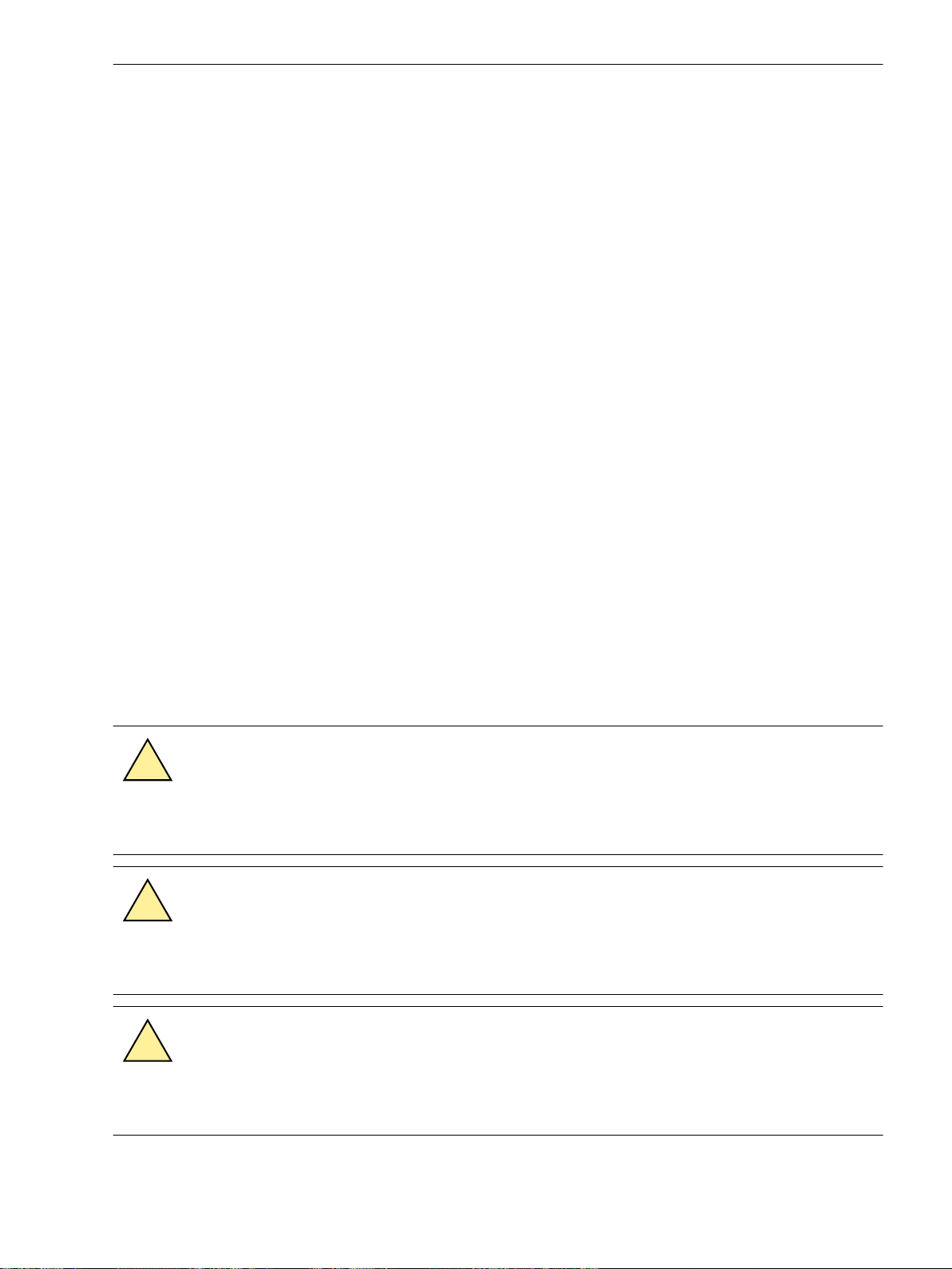
1.4.2 SICAM PQS/SICAM PQ Analyzer.................................................................................... 25
1.5 Scope of Functions............................................................................................................28
2 Basic Structure of the Function.................................................................................................................. 31
2.1 Function Embedding in the Device.................................................................................... 32
2.2 Adjustment of Application Templates/Functional Scope..................................................... 35
2.3 Function Control .............................................................................................................. 37
2.4 Text Structure and Reference Number for Parameter and Indications .................................39
3 System Functions....................................................................................................................................... 41
3.1 Indications........................................................................................................................42
3.1.1 General ...................................................................................................................... 42
3.1.2 Reading Indications on the On-Site Operation Panel .................................................... 42
3.1.3 Reading Indications from the PC with DIGSI 5...............................................................44
3.1.4 Display of Indications ..................................................................................................45
3.1.5 Logs............................................................................................................................ 46
3.1.5.1 General .................................................................................................................46
3.1.5.2 Operational Log .................................................................................................... 47
3.1.5.3 User-Defined Log .................................................................................................. 49
3.1.5.4 Sequence of Events Log......................................................................................... 52
3.1.6 Setting-History Log ..................................................................................................... 54
3.1.7 Communication Log.................................................................................................... 56
3.1.8 Security Log ................................................................................................................57
3.1.9 Device-Diagnosis Log .................................................................................................. 59
3.1.10 Saving and Deleting the Log ....................................................................................... 60
3.1.11 Stored Indications in the SIPROTEC 5 Device ................................................................62
3.1.12 Test Mode and Influence of Indications on Substation Automation Technology ............64
3.2 Measured-Value Acquisition ............................................................................................. 65
3.3 Processing Quality Attributes.............................................................................................67
3.3.1 Overview.....................................................................................................................67
3.3.2 Quality Processing/Affected by the User for Received GOOSE Values............................. 69
SIPROTEC 5, Fault Recorder, Manual 9
C53000-G5040-C018-5, Edition 11.2017

Table of Contents
3.3.3 Quality Processing/Affected by the User in CFC Charts.................................................. 74
3.3.4 Quality Processing/Affected by the User in Internal Device Functions............................ 78
3.4 Date and Time Synchronization......................................................................................... 82
3.4.1 Overview of Functions.................................................................................................82
3.4.2 Structure of the Function.............................................................................................82
3.4.3 Function Description....................................................................................................82
3.4.4 Settings.......................................................................................................................85
3.4.5 Information List...........................................................................................................86
3.5 User-Defined Objects........................................................................................................ 87
3.5.1 Overview.....................................................................................................................87
3.5.2 Basic Data Types.......................................................................................................... 88
3.5.3 Energy Metered Values ............................................................................................... 91
3.5.4 Additional Data Types.................................................................................................. 91
3.5.5 External Signals........................................................................................................... 91
3.6 Other Functions................................................................................................................ 92
3.6.1 Indication Filtering and Chatter Blocking for Input Signals ........................................... 92
3.7 General Notes for Setting the Threshold Value of Trigger Functions................................... 95
3.7.1 Overview ....................................................................................................................95
3.7.2 Modifying the Transformer Ratios in DIGSI 5 ................................................................95
3.7.3 Changing the Transformation Ratios of the Transformer on the Device ...................... 102
4 Applications..............................................................................................................................................103
4.1 Overview........................................................................................................................ 104
4.2 Application Template and Functional Scope for the Fault Recorder ..................................105
5 Power-System Data...................................................................................................................................109
5.1 Overview........................................................................................................................ 110
5.2 Structure of the Power-System Data................................................................................ 111
5.3 Application and Setting Notes – General Settings............................................................ 112
5.4 Application and Setting Notes for Measuring Point Current 3-Phase (I-3ph)......................113
5.5 Application and Setting Notes for Measuring Point Current 1-Phase (I-1ph)......................116
5.6 Application and Setting Notes for Measuring Point Voltage 3-Phase (V-3ph).....................118
5.7 Application and Setting Notes for Measuring Point Voltage 1-Phase (V-1ph).....................122
5.8 Settings.......................................................................................................................... 124
5.9 Information List.............................................................................................................. 131
6 Function-Group Types.............................................................................................................................. 135
6.1 Function-Group Type Voltage 3-Phase............................................................................. 136
6.1.1 Overview...................................................................................................................136
6.1.2 Structure of the Function Group................................................................................ 136
6.1.3 Application and Setting Notes....................................................................................138
6.1.4 Settings.....................................................................................................................138
6.1.5 Information List.........................................................................................................139
6.2 Function-Group Type Voltage/current 1-Phase................................................................. 140
6.2.1 Overview of Functions...............................................................................................140
6.2.2 Structure of the Function Group................................................................................ 140
6.2.3 Application and Setting Notes....................................................................................143
10 SIPROTEC 5, Fault Recorder, Manual
C53000-G5040-C018-5, Edition 11.2017

Table of Contents
6.2.4 Write-Protected Settings............................................................................................ 144
6.2.5 Settings.....................................................................................................................144
6.2.6 Information List.........................................................................................................144
6.3 Function-Group Type Voltage/current 3-Phase................................................................. 145
6.3.1 Overview...................................................................................................................145
6.3.2 Structure of the Function Group................................................................................ 146
6.3.3 Application and Setting Notes ................................................................................... 149
6.3.4 Settings.....................................................................................................................150
6.3.5 Information List.........................................................................................................150
6.4 Function-Group Type Phasor Measurement Unit (PMU)....................................................152
6.4.1 Overview of Functions...............................................................................................152
6.4.2 Structure of the Function Group................................................................................ 152
6.4.3 Function Description..................................................................................................152
6.4.4 Transmitted Data.......................................................................................................157
6.4.5 PMU Communication (IEEE C37.118)......................................................................... 157
6.4.6 Parameterizing the PMU with DIGSI............................................................................158
6.4.7 Parameterizing the PMU on the Device.......................................................................167
6.4.8 Application and Setting Notes....................................................................................169
6.4.9 Settings.....................................................................................................................170
6.4.10 Information List.........................................................................................................170
6.5 Function-Group Type Analog Units.................................................................................. 171
6.5.1 Overview...................................................................................................................171
6.5.2 Structure of the Function Group................................................................................ 171
6.5.3 20-mA Unit Ethernet..................................................................................................173
6.5.3.1 Overview ............................................................................................................ 173
6.5.3.2 Structure of the Function..................................................................................... 173
6.5.3.3 Communication with 20-mA Unit Ethernet .......................................................... 174
6.5.3.4 Application and Setting Notes ............................................................................. 175
6.5.3.5 20-mA Channel....................................................................................................175
6.5.3.6 Application and Setting Notes.............................................................................. 178
6.5.3.7 Settings............................................................................................................... 179
6.5.3.8 Information List................................................................................................... 180
6.5.4 20-mA Unit Serial...................................................................................................... 180
6.5.4.1 Overview ............................................................................................................ 180
6.5.4.2 Application and Setting Notes.............................................................................. 180
6.5.4.3 Settings............................................................................................................... 182
6.5.4.4 Information List................................................................................................... 183
6.5.5 Communication with 20-mA Unit...............................................................................183
6.5.5.1 Integration of a Serial 20-mA Unit ........................................................................183
6.5.5.2 Integration of a 20-mA Unit Ethernet ...................................................................186
6.5.6 V/I-Measuring-Transducer Unit with Fast Inputs..........................................................188
6.5.6.1 Overview............................................................................................................. 188
6.5.6.2 Structure of the Function..................................................................................... 189
6.5.6.3 Function Description............................................................................................ 189
6.5.6.4 Application and Setting Notes.............................................................................. 190
6.5.6.5 Settings............................................................................................................... 194
6.5.6.6 Information List................................................................................................... 196
6.5.7 RTD Unit Ethernet......................................................................................................196
6.5.7.1 Overview............................................................................................................. 196
6.5.7.2 Structure of the Function..................................................................................... 196
6.5.7.3 Communication with an RTD Unit ........................................................................ 197
SIPROTEC 5, Fault Recorder, Manual 11
C53000-G5040-C018-5, Edition 11.2017

Table of Contents
6.5.7.4 Application and Setting Notes.............................................................................. 198
6.5.7.5 Temperature Sensor.............................................................................................199
6.5.7.6 Application and Setting Notes ............................................................................. 199
6.5.7.7 Settings............................................................................................................... 200
6.5.7.8 Information List................................................................................................... 201
6.5.8 RTD Unit, Serial..........................................................................................................203
6.5.8.1 Overview ............................................................................................................ 203
6.5.8.2 Application and Setting Notes ............................................................................. 203
6.5.8.3 Settings............................................................................................................... 203
6.5.8.4 Information List................................................................................................... 204
6.5.9 Communication with RTD Unit................................................................................... 206
6.5.9.1 Integration of a Serial RTD Unit (Ziehl TR1200) .....................................................206
6.5.9.2 Integration of an RTD-Unit Ethernet (TR1200 IP) .................................................. 208
6.5.9.3 Temperature Simulation without Sensors ............................................................ 211
7 Fault Recorder.......................................................................................................................................... 213
7.1 Introduction to DIGSI 5....................................................................................................214
7.1.1 General..................................................................................................................... 214
7.1.2 Step 1: Creating a New Project and Adding a New Device .......................................... 214
7.1.3 Step 2: Setting the Parameters and Routing in DIGSI 5 ...............................................217
7.1.4 Step 3: Evaluating Recordings.................................................................................... 225
7.1.5 Working with IEC 61850............................................................................................ 228
7.2 Function-Group Type Recorder........................................................................................ 231
7.2.1 Overview of Functions .............................................................................................. 231
7.2.2 Structure of the Function Group................................................................................ 231
7.2.3 Function Description..................................................................................................232
7.2.4 Application and Setting Notes – General Settings....................................................... 234
7.2.5 Time Jumps............................................................................................................... 235
7.2.6 Fast-Scan Recorder.................................................................................................... 236
7.2.6.1 Overview of Functions......................................................................................... 236
7.2.6.2 Structure of the Function .................................................................................... 236
7.2.6.3 Function Description ........................................................................................... 236
7.2.6.4 Application and Setting Notes ............................................................................. 238
7.2.6.5 Settings............................................................................................................... 240
7.2.6.6 Information List................................................................................................... 240
7.2.7 Slow-Scan Recorder................................................................................................... 241
7.2.7.1 Overview of Functions .........................................................................................241
7.2.7.2 Structure of the Function .................................................................................... 241
7.2.7.3 Function Description ........................................................................................... 241
7.2.7.4 Application and Setting Notes ............................................................................. 244
7.2.7.5 Settings............................................................................................................... 246
7.2.7.6 Information List................................................................................................... 246
7.2.8 Continuous Recorder................................................................................................. 247
7.2.8.1 Overview of Functions .........................................................................................247
7.2.8.2 Structure of the Function .................................................................................... 247
7.2.8.3 Function Description ........................................................................................... 247
7.2.8.4 Application and Setting Notes ............................................................................. 248
7.2.8.5 Settings............................................................................................................... 249
7.2.8.6 Information List................................................................................................... 250
7.2.9 Trend Recorder.......................................................................................................... 250
7.2.9.1 Overview of Functions .........................................................................................250
7.2.9.2 Structure of the Function .................................................................................... 250
7.2.9.3 Function Description ........................................................................................... 250
7.2.9.4 Application and Setting Notes ............................................................................. 252
12 SIPROTEC 5, Fault Recorder, Manual
C53000-G5040-C018-5, Edition 11.2017

Table of Contents
7.2.9.5 Settings............................................................................................................... 252
7.2.9.6 Information List................................................................................................... 253
7.2.10 Sequence of Events................................................................................................... 253
7.2.10.1 Overview of Functions......................................................................................... 253
7.2.11 Flow Control of Fault Records (Fast-Scan and Slow-Scan Recorder)............................. 253
7.2.11.1 Function Description of the Retrigger Blocking Time ............................................ 253
7.2.11.2 Triggering Without the Retrigger Blocking Time ................................................... 254
7.2.11.3 Triggering With the Retrigger Blocking Time......................................................... 255
7.3 Function Description Analog and Binary Triggers............................................................. 262
7.3.1 Overview of Functions .............................................................................................. 262
7.3.2 Function Description Analog Trigger.......................................................................... 262
7.3.2.1 Structure of the Analog Trigger............................................................................ 262
7.3.2.2 Trigger Functions of the Analog Trigger ...............................................................263
7.3.2.3 Level Trigger ....................................................................................................... 264
7.3.2.4 Gradient Trigger (dM/dt) ......................................................................................264
7.3.3 Function Description Binary Trigger........................................................................... 265
7.3.3.1 Manual Trigger Start............................................................................................ 265
7.3.3.2 External Trigger Start ...........................................................................................268
7.3.3.3 GOOSE Trigger .................................................................................................... 268
7.3.3.4 Trigger Start Using Logic Block Chart.................................................................... 269
7.3.3.5 Triggers on Indications ........................................................................................ 269
7.4 Trigger Functions 1-Phase............................................................................................... 271
7.4.1 Voltage Trigger..........................................................................................................271
7.4.1.1 Overview of Functions......................................................................................... 271
7.4.1.2 Structure of the Function..................................................................................... 271
7.4.1.3 Function Description............................................................................................ 271
7.4.1.4 Application and Setting Notes Trig V RMS (RMS Value)..........................................273
7.4.1.5 Application and Setting Notes Trig V Fund (Fundamental Component)..................274
7.4.1.6 Settings............................................................................................................... 276
7.4.1.7 Information List................................................................................................... 277
7.4.2 Current Trigger..........................................................................................................277
7.4.2.1 Overview of Functions......................................................................................... 277
7.4.2.2 Structure of the Function .................................................................................... 277
7.4.2.3 Function Description............................................................................................ 278
7.4.2.4 Application and Setting Notes I RMS Trig.............................................................. 279
7.4.2.5 Application and Setting Notes I Fund. Trig............................................................ 281
7.4.2.6 Settings............................................................................................................... 282
7.4.2.7 Information List................................................................................................... 284
7.4.3 Frequency Trigger..................................................................................................... 285
7.4.3.1 Overview of Functions......................................................................................... 285
7.4.3.2 Structure of the Function..................................................................................... 285
7.4.3.3 Function Description............................................................................................ 285
7.4.3.4 Application and Setting Notes - Frequency Trigger................................................287
7.4.3.5 Settings............................................................................................................... 288
7.4.3.6 Information List................................................................................................... 289
7.4.4 Power Trigger............................................................................................................289
7.4.4.1 Overview of Functions......................................................................................... 289
7.4.4.2 Structure of the Function..................................................................................... 289
7.4.4.3 Function Description............................................................................................ 290
7.4.4.4 Application and Setting Notes – Trigger P............................................................. 291
7.4.4.5 Application and Setting Notes – Trigger Q............................................................ 293
7.4.4.6 Settings............................................................................................................... 294
7.4.4.7 Information List................................................................................................... 296
SIPROTEC 5, Fault Recorder, Manual 13
C53000-G5040-C018-5, Edition 11.2017

Table of Contents
7.5 Trigger Functions 3-Phase............................................................................................... 297
7.5.1 Voltage Trigger..........................................................................................................297
7.5.1.1 Overview of Functions .........................................................................................297
7.5.1.2 Structure of the Function .................................................................................... 297
7.5.1.3 Function Description............................................................................................ 297
7.5.1.4 Application and Setting Notes Trig V Fund (Fundamental Component)..................299
7.5.1.5 Application and Setting Notes Trig V RMS (RMS Value)..........................................302
7.5.1.6 Application and Setting Notes - V0 Trigger (Zero-Sequence System)......................305
7.5.1.7 Application and Setting Notes - V1 Trigger (Positive-Sequence System)................. 306
7.5.1.8 Application and Setting Notes - V2 Trigger (Negative-Sequence System)............... 307
7.5.1.9 Settings............................................................................................................... 308
7.5.1.10 Information List................................................................................................... 312
7.5.2 Current Trigger..........................................................................................................312
7.5.2.1 Overview of Functions .........................................................................................312
7.5.2.2 Structure of the Function .................................................................................... 312
7.5.2.3 Function Description............................................................................................ 313
7.5.2.4 Application and Setting Notes I Fund. Trig............................................................ 315
7.5.2.5 Application and Setting Notes Trigger I RMS......................................................... 317
7.5.2.6 Application and Setting Notes - I0 Trigger (Zero-Sequence System).......................320
7.5.2.7 Application and Setting Notes I1 Trigger (Positive-Sequence System).................... 321
7.5.2.8 Application and Setting Notes - I2 Trigger (Negative-Sequence System)................ 322
7.5.2.9 Settings............................................................................................................... 323
7.5.2.10 Information List................................................................................................... 330
7.5.3 Frequency Trigger..................................................................................................... 331
7.5.3.1 Overview of Functions......................................................................................... 331
7.5.3.2 Structure of the Function .................................................................................... 331
7.5.3.3 Function Description............................................................................................ 332
7.5.3.4 Application and Setting Notes - Frequency Trigger................................................333
7.5.3.5 Settings............................................................................................................... 334
7.5.3.6 Information List................................................................................................... 335
7.5.4 Power Trigger............................................................................................................335
7.5.4.1 Overview of Functions......................................................................................... 335
7.5.4.2 Structure of the Function..................................................................................... 335
7.5.4.3 Function Description ........................................................................................... 336
7.5.4.4 Application and Setting Notes Trigger Psum..........................................................338
7.5.4.5 Application and Setting Notes Qsum Trig..............................................................339
7.5.4.6 Application and Setting Notes Trigger Ssum..........................................................341
7.5.4.7 Function Description Trigger Power Swing............................................................342
7.5.4.8 Application and Setting Notes, Trigger Power Swing............................................. 343
7.5.4.9 Settings............................................................................................................... 344
7.5.4.10 Information List................................................................................................... 346
7.6 Measurands and Recorder Routing Functions...................................................................348
7.6.1 Measurands...............................................................................................................348
7.6.1.1 Properties of Measurands .................................................................................... 348
7.6.1.2 Using Measurands ...............................................................................................348
7.6.1.3 Routing the Measurands in DIGSI 5 for Processing in SICAM PQS........................... 353
7.6.2 Recorder Routing V.................................................................................................... 353
7.6.2.1 Overview of Functions......................................................................................... 353
7.6.2.2 Structure of the Function..................................................................................... 353
7.6.2.3 Indications .......................................................................................................... 353
7.6.2.4 Application and Setting Notes.............................................................................. 354
7.6.2.5 Settings............................................................................................................... 354
7.6.2.6 Information List................................................................................................... 355
7.6.3 Recorder Routing VI 1-Phase...................................................................................... 356
7.6.3.1 Overview of Functions......................................................................................... 356
7.6.3.2 Structure of the Function..................................................................................... 356
14 SIPROTEC 5, Fault Recorder, Manual
C53000-G5040-C018-5, Edition 11.2017

Table of Contents
7.6.3.3 Application and Setting Notes ............................................................................. 356
7.6.3.4 Information List................................................................................................... 356
7.6.4 Recorder Routing VI 3-Phase...................................................................................... 357
7.6.4.1 Overview of Functions......................................................................................... 357
7.6.4.2 Structure of the Function..................................................................................... 357
7.6.4.3 Application and Setting Notes.............................................................................. 357
7.6.4.4 Settings............................................................................................................... 358
7.6.4.5 Information List................................................................................................... 358
7.6.5 V/I Measuring-Transducer Unit with Fast Inputs..........................................................360
7.6.5.1 Overview of Functions......................................................................................... 360
7.6.5.2 Information List................................................................................................... 360
8 Supervision Functions.............................................................................................................................. 361
8.1 Overview........................................................................................................................ 362
8.2 Resource-Consumption Supervision.................................................................................363
8.2.1 Load Model............................................................................................................... 363
8.2.2 Function Points..........................................................................................................364
8.2.3 CFC Resources........................................................................................................... 365
8.3 Supervision of the Secondary System.............................................................................. 367
8.3.1 Signaling-Voltage Supervision....................................................................................367
8.3.1.1 Overview of Functions......................................................................................... 367
8.3.1.2 Structure of the Function..................................................................................... 367
8.3.1.3 Function Description............................................................................................ 367
8.3.1.4 Application and Setting Notes.............................................................................. 369
8.3.1.5 Settings............................................................................................................... 370
8.3.1.6 Information List................................................................................................... 372
8.3.2 Voltage-Balance Supervision...................................................................................... 372
8.3.2.1 Overview of Functions .........................................................................................372
8.3.2.2 Structure of the Function..................................................................................... 372
8.3.2.3 Function Description............................................................................................ 372
8.3.2.4 Application and Setting Notes.............................................................................. 374
8.3.2.5 Settings............................................................................................................... 374
8.3.2.6 Information List................................................................................................... 374
8.3.3 Voltage-Sum Supervision........................................................................................... 375
8.3.3.1 Overview of Functions .........................................................................................375
8.3.3.2 Structure of the Function .................................................................................... 375
8.3.3.3 Function Description............................................................................................ 375
8.3.3.4 Application and Setting Notes.............................................................................. 377
8.3.3.5 Settings............................................................................................................... 377
8.3.3.6 Information List................................................................................................... 377
8.3.4 Voltage Phase-Rotation Supervision........................................................................... 378
8.3.4.1 Overview of Functions .........................................................................................378
8.3.4.2 Structure of the Function .................................................................................... 378
8.3.4.3 Function Description............................................................................................ 378
8.3.4.4 Application and Setting Notes ............................................................................. 379
8.3.4.5 Settings............................................................................................................... 379
8.3.4.6 Information List................................................................................................... 379
8.3.5 Broken-Wire Detection...............................................................................................380
8.3.5.1 Overview of Functions .........................................................................................380
8.3.5.2 Structure of the Function..................................................................................... 380
8.3.5.3 Function Description............................................................................................ 381
8.3.5.4 Application and Setting Notes.............................................................................. 383
8.3.5.5 Settings............................................................................................................... 383
8.3.5.6 Information List................................................................................................... 383
SIPROTEC 5, Fault Recorder, Manual 15
C53000-G5040-C018-5, Edition 11.2017

Table of Contents
8.3.6 Current-Balance Supervision...................................................................................... 384
8.3.6.1 Overview of Functions .........................................................................................384
8.3.6.2 Structure of the Function .................................................................................... 384
8.3.6.3 Function Description............................................................................................ 384
8.3.6.4 Application and Setting Notes.............................................................................. 385
8.3.6.5 Settings............................................................................................................... 386
8.3.6.6 Information List................................................................................................... 386
8.3.7 Current-Sum Supervision........................................................................................... 386
8.3.7.1 Overview of Functions .........................................................................................386
8.3.7.2 Structure of the Function..................................................................................... 387
8.3.7.3 Function Description............................................................................................ 387
8.3.7.4 Application and Setting Notes.............................................................................. 389
8.3.7.5 Settings............................................................................................................... 389
8.3.7.6 Information List................................................................................................... 390
8.3.8 Current Phase-Rotation Supervision........................................................................... 390
8.3.8.1 Overview of Functions .........................................................................................390
8.3.8.2 Structure of the Function .................................................................................... 390
8.3.8.3 Function Description............................................................................................ 391
8.3.8.4 Application and Setting Notes ............................................................................. 392
8.3.8.5 Settings............................................................................................................... 392
8.3.8.6 Information List................................................................................................... 392
8.4 Supervision of the Device Hardware................................................................................ 393
8.4.1 Overview...................................................................................................................393
8.4.2 Analog-Channel Supervision via Fast Current-Sum......................................................394
8.4.2.1 Overview of Functions......................................................................................... 394
8.4.2.2 Structure of the Function..................................................................................... 395
8.4.2.3 Function Description............................................................................................ 395
8.5 Supervision of Device Firmware.......................................................................................398
8.6 Supervision of Hardware Configuration........................................................................... 399
8.7 Supervision of Communication Connections....................................................................400
8.8 Error Responses and Corrective Measures........................................................................ 401
8.8.1 Overview...................................................................................................................401
8.8.2 Defect Severity 1....................................................................................................... 402
8.8.3 Defect Severity 2....................................................................................................... 405
8.8.4 Defect Severity 3....................................................................................................... 406
8.8.5 Defect Severity 4 (Group Alarm).................................................................................407
8.9 Group Indications............................................................................................................409
9 Measured and Energy Values................................................................................................................... 411
9.1 Overview of Functions.................................................................................................... 412
9.2 Structure of the Function................................................................................................ 413
9.3 Operational Measured Values..........................................................................................414
9.4 Fundamental and Symmetrical Components....................................................................416
9.5 Average Values............................................................................................................... 417
9.5.1 Function Description of Average Values..................................................................... 417
9.5.2 Application and Setting Notes for Average Values...................................................... 417
9.6 Minimum/Maximum Values.............................................................................................420
9.6.1 Function Description of Minimum/Maximum Values...................................................420
9.6.2 Application and Setting Notes for Minimum/Maximum Values....................................421
16 SIPROTEC 5, Fault Recorder, Manual
C53000-G5040-C018-5, Edition 11.2017

Table of Contents
10 Functional Tests........................................................................................................................................423
10.1 Overview ....................................................................................................................... 424
10.2 Directional Test .............................................................................................................. 425
11 Technical Data.......................................................................................................................................... 427
11.1 General Device Data........................................................................................................428
11.1.1 Supply Voltage.......................................................................................................... 428
11.1.2 Binary Inputs............................................................................................................. 429
11.1.3 Relay Outputs............................................................................................................430
11.1.4 Design Data...............................................................................................................432
11.1.5 Influencing Variables for Measured Values ................................................................ 434
11.1.6 SDHC Memory Card .................................................................................................. 434
11.2 Date and Time Synchronization ...................................................................................... 436
11.3 Phasor Measurement Unit............................................................................................... 437
11.4 Recorder Functions......................................................................................................... 438
11.4.1 Fast-Scan Recorder.................................................................................................... 438
11.4.2 Slow-Scan Recorder................................................................................................... 438
11.4.3 Continuous Recorder................................................................................................. 439
11.4.4 Trend Recorder.......................................................................................................... 439
11.4.5 Measured Values and Binary Inputs ........................................................................... 439
11.5 Supervision Functions..................................................................................................... 441
11.5.1 Voltage-Balance Supervision ..................................................................................... 441
11.5.2 Voltage-Sum Supervision........................................................................................... 441
11.5.3 Voltage Phase-Rotation Supervision .......................................................................... 441
11.5.4 Broken-Wire Detection .............................................................................................. 442
11.5.5 Current-Balance Supervision...................................................................................... 442
11.5.6 Current-Sum Supervision........................................................................................... 442
11.5.7 Current Phase-Rotation Supervision ...........................................................................443
11.5.8 Analog Channel Supervision via Fast Current Sum ..................................................... 443
11.6 Operational Measured Values and Statistical Values.........................................................444
11.7 CFC.................................................................................................................................448
A Appendix.................................................................................................................................................. 453
A.1 Order Configurator and Order Options.............................................................................454
A.2 Typographic and Symbol Conventions.............................................................................455
A.3 Standard Variants for 7KE85............................................................................................458
A.4 Connection Examples for Current Transformers............................................................... 462
A.5 Connection Examples of Voltage Transformers for Modular Devices.................................465
A.6 Application Examples of the Fault Recorder .................................................................... 468
A.7 Shielding Concept ..........................................................................................................471
A.8 SDHC Memory Card ........................................................................................................472
A.9 Troubleshooting SDHC Memory Card ..............................................................................474
Glossary.................................................................................................................................................... 475
Index.........................................................................................................................................................487
SIPROTEC 5, Fault Recorder, Manual 17
C53000-G5040-C018-5, Edition 11.2017

18 SIPROTEC 5, Fault Recorder, Manual
C53000-G5040-C018-5, Edition 11.2017

1
Introduction
1.1 General 20
1.2 Properties of SIPROTEC 5 21
1.3 Properties of the Fault Recorder 23
1.4 Parameterization and Analysis Software 25
1.5 Scope of Functions 28
SIPROTEC 5, Fault Recorder, Manual 19
C53000-G5040-C018-5, Edition 11.2017

Introduction
1.1 General
1.1
General
The protection of power distribution equipment is crucial in assuring a reliable electricity supply. The user
expects full availability of electrical energy at a consistently high standard of quality. Thus, for power-system
protection, for example, it is becoming increasingly difficult to distinguish between critical load cases and
short-circuits with minimum fault currents. The demands on optimum use and the corresponding parameterization of protection devices are rising. Intensive evaluation of available information from secondary equipment (using fault recorders) is therefore essential. This is the only way to ensure today's currently high levels
of reliability and availability in electricity transmission and distribution systems for the future as well.
A new era has begun for fault recording with the introduction of the SIPROTEC 5 series. The 7KE85 fault
recorder was developed especially for the requirements of the changing energy market, both current and
future. Powerful, reliable monitoring, combined with the flexible engineering and communication options,
offers the basis for maximum reliability of supply.
20 SIPROTEC 5, Fault Recorder, Manual
C53000-G5040-C018-5, Edition 11.2017

Introduction
1.2 Properties of SIPROTEC 5
1.2
General Properties
Properties of SIPROTEC 5
The SIPROTEC 5 devices at the bay level are compact and can be installed directly in medium- and high-voltage
switchgear. They are characterized by seamless integration of fault recorder, protection, and control functions.
Powerful microprocessor
•
Fully digital measured-value processing and control, from sampling and digitizing of measurands to
•
closing and tripping decisions for the circuit breaker
Complete galvanic and interference-free isolation of the internal processing switches from the system
•
measuring, control, and supply circuits through instrument transformers, binary input and output
modules, and DC and AC voltage converters
Easy operation via an integrated operation and display panel, or via a connected personal computer with
•
user interface
Continuous calculation and presentation of measured values on the front display
•
Storage of min/max measured values and storage of long-term average values
•
Storage of fault indications for system incidents (faults in system) with real-time assignment and instan-
•
taneous values for fault recording
Continuous monitoring of the measurands as well as the device hardware and software
•
Communication with central control and storage devices possible via the device interface
•
Battery-buffered, synchronizable clock
•
Microcomputer System
All device functions are processed in the microcomputer system.
This includes, for example:
Filtering and preparation of the measurands
•
Constant monitoring of the measurands
•
Monitoring of the trigger conditions for the individual functions
•
Querying of limiting values and time-outs
•
Controlling of signals for the logic functions
•
Storage of indications, fault data, and fault values for fault analysis
•
Administration of the operating system and its functions, such as data storage, real-time clock, communi-
•
cation, interfaces, etc.
External distribution of information
•
Modular Concept
The SIPROTEC 5 modular concept ensures the consistency and integrity of all functionalities across the entire
device series. Significant features here include:
Modular system design in hardware, software, and communication
•
The same expansion and communication modules for all devices in the SIPROTEC 5 family
•
Innovative terminal technology with easy assembly and interchangeability and the highest possible
•
degree of safety
The same functions can be configured individually across the entire family of devices
•
Ability to upgrade with innovations possible at all times through libraries
•
Open, scalable architecture for IT integration and new functions
•
SIPROTEC 5, Fault Recorder, Manual 21
C53000-G5040-C018-5, Edition 11.2017

Introduction
1.2 Properties of SIPROTEC 5
Multi-layered security mechanisms in all links of the security chain
•
Self-monitoring routines for reliable localization and indication of device faults
•
Automatic logging of access attempts and safety-critical operations on the devices and systems
•
Analog Inputs
The measuring inputs transform the currents and voltages coming from the instrument transformers and
adapt them to the internal processing level of the device. A SIPROTEC 5 device has current and/or voltage
transmitters. The current inputs are therefore intended for the detection of phase currents and ground
current. The ground current can be detected sensitively using a core balance current transformer. In addition,
phase currents can be detected very sensitively for a particularly precise measurement.
The voltage inputs detect the measuring voltage of device functions requiring current and voltage measured
values.
The analog values are digitized in the internal microcomputer for data processing.
Binary Inputs and Outputs
The device receives information from the system or from other devices via the binary inputs and outputs. Indications are generated for the remote signaling of important events and states.
Front Elements
For devices with an integrated or detached operation panel, LEDs and an LC display on the front provide information on the device function and report events, states, and measured values. In conjunction with the LC
display, the integrated keypad enables on-site operation of the device. All device information such as setting
parameters, operating and fault indications or measured values can be displayed, and setting parameters
changed.
USB Interface and Serial Interfaces
The USB interface in the front cover enables communication with a personal computer when using the DIGSI 5
operating program. As a result, the operation of all device functions is possible. Additional interfaces on the
back are used to realize various communication protocols.
Redundant Communication
SIPROTEC 5 devices maintain complete communication redundancy:
Multiple redundant communication interfaces
•
Redundant and independent protocols for control centers possible (such as IEC 61850, either single or
•
redundant)
Redundant time synchronization (such as IRIG-B and SNTP)
•
Power Supply
The individual functional units of the device are powered by an internal power supply. Brief interruptions in
the supply voltage, which can occur during short circuits in the system auxiliary voltage supply, are bridged by
capacitor storage (see also the Technical Data).
22 SIPROTEC 5, Fault Recorder, Manual
C53000-G5040-C018-5, Edition 11.2017

Introduction
1.3 Properties of the Fault Recorder
1.3
Properties of the Fault Recorder
The 7KE85 fault recorder is built on the flexible and powerful SIPROTEC 5 modular system and can thus also be
used universally in the scope of system solutions. The 7KE85 fault recorder is able to acquire extensive data,
such as measured values and sampled values (SAV), with high precision. It features a large number of analog
and binary inputs and a high sampling frequency. All data are recorded either by way of continuous criteria or
by way of different trigger criteria. Besides storing the data on internal mass storage, they can also transmit it
to central analysis systems. Consequently, you are able to monitor systems for typical characteristics.
The fault recorder continuously records on the one side via the trend recorder and the continuous recorder.
On the other side, the fault recorder records analog and binary data during a fault, for example, a change in
voltage, short circuits or ground faults, using the triggered fast-scan or slow-scan recorders. The 7KE85 fault
recorder captures this high-precision, time-stamped record, including calculated measurands (such as, for
example, power or frequency), for later evaluation. The evaluation is done after reading out from the device
through DIGSI 5 via SIGRA or via the powerful fault record and PQ data analysis system SICAM PQS/SICAM PQ
Analyzer. Recorded data is archived on internal mass storage to prevent data loss in case of a loss of supply
voltage. Recording of faults ensures long recordings with outstanding accuracy. The 7KE fault recorder
captures and processes the measurands and events according to the IEC 61000-4-30 and IEC 61000-4-15
standards.
Poor power quality can lead to a power failure. Effects on power quality consist of and are created chiefly by
large loads (for example, industrial processes), changes in the current network status (switching operations)
and by external effects (for example, lightning). Power quality standards (for example, EN 50160) are used to
specify limits for electric measurands within which connected devices operate properly without large power
losses. The fault recorder is used as a power quality recorder and evaluation device to show the power quality
of an electricity-supply system.
The fault recorder has the following properties:
Embedding in the SIPROTEC 5 family with:
•
- A consistent hardware concept
- Numerous expansion modules
- DIGSI 5 as configuration tool
- A broad selection of functionalities on the basis of function points
Fault recording and continuous recording for use in medium-, high-, and ultra high-voltage systems
•
(substations) and in power plants
1 x Fast-scan recorder
2 x Slow-scan recorder
5 x Continuous recorder
2 x Trend recorder
Event recorder for binary signals for monitoring of diverse components, such as circuit breakers, discon-
•
nectors, etc.
PMU communication acc. to IEEE C37.118 standard
•
IEC 61850 communication
•
Sampling frequencies can be set from 1 kHz to 16 kHz
•
Time synchronization via IRIG-B, DCF77, and SNTP
•
External mass storage (Siemens SDHC memory card only) with 16 GB
•
Flexible routing:
•
- Any desired routing of the measured values on each recorder
- Free combination of the measuring groups for the power calculation
Recorded quality code:
•
- Quality characteristic for each recorded value as well as display of this characteristic in SIGRA/SICAM PQ
Analyzer
Recording GOOSE signals
•
SIPROTEC 5, Fault Recorder, Manual 23
C53000-G5040-C018-5, Edition 11.2017

Introduction
1.3 Properties of the Fault Recorder
Triggering on GOOSE signals via Continuous Function Chart
•
Creation of flexible trigger conditions through use of logic block charts (Continuous Function Chart)
•
Specifying the limits for electrical measurands
•
Monitoring power network quality (Power Quality Monitoring) according to EN 50160
•
Measuring flicker according to IEC 61000-4-15
•
Additional functions for simple tests and for commissioning
•
24 SIPROTEC 5, Fault Recorder, Manual
C53000-G5040-C018-5, Edition 11.2017

Introduction
1.4 Parameterization and Analysis Software
1.4
1.4.1
Description
1.4.2
Description
Parameterization and Analysis Software
DIGSI 5
DIGSI 5 is the versatile engineering tool for parameterization, commissioning, and operating all SIPROTEC 5
devices. Its innovative user interface includes context-sensitive user instructions. Simple connection to the
device via USB and Ethernet IF enables you to work with a device easily and efficiently. The full capabilities of
DIGSI 5 are revealed when you connect it to a network of protection devices: Then you can work with all of the
devices in a substation in one project.
DIGSI 5 offers superior usability and is optimized for your work processes. Only the information you actually
need to carry out your tasks is shown. These can be reduced further via expanded filter mechanisms. Consistent use of sophisticated and standardized mechanisms in the user interfaces requires less training. DIGSI 5 is
tailored to specific requirements. The free software variant DIGSI 5 Compact offers everything that is required
for a single device. The DIGSI 5 Standard Version is suitable for complex scenarios with several devices.
DIGSI 5 Premium contains the full functionality you need to raise your productivity to a new level.
SICAM PQS/SICAM PQ Analyzer
Siemens SICAM PQS allows all fault records and network quality data (PQ data) to be analyzed in one system.
The protection of power distribution equipment is crucial in assuring a reliable electricity supply. The user
expects full availability of electrical energy at a consistently high standard of quality. Thus, for power-system
protection, for example, it is becoming increasingly difficult to distinguish between critical load cases and
short-circuits with minimum fault currents. The demands on optimum use and the corresponding parameterization of protection devices are rising. Intensive evaluation of available information from secondary equipment using fault recorders is therefore essential. This is the only way to ensure today's currently high levels of
reliability and availability in electricity transmission and distribution systems for the future as well. Additionally, the growing use of power electronics often has a noticeable impact on power quality. The result is poor
power quality, which can cause interruptions, production outages, and high follow-up costs.
Compliance with the generally valid quality criteria for electricity-supply systems as defined in standards (for
example, EN 50160) is therefore vital. The basis must be reliable recording and assessment of all quality
parameters. Weak points and potential fault sources can be identified early on and systematically eliminated.
With the software solution SICAM PQS, Siemens is setting new standards: For the first time, it is possible to
evaluate and archive centrally all network quality data from the bay level with one integrated software solution in a vendor-neutral manner. This gives you a quick and uncomplicated overview of the quality of your
system. With SICAM PQS, you can keep an eye on all relevant data: Fault records as well as all network quality
measured data. For combined applications, SICAM PQS is also easy to expand to a substation automation
system.
User Benefit
Secured power quality for the supply of your plant
•
Fast, transparent analysis of the cause and development of a system incident
•
Efficient personnel deployment for troubleshooting
•
Intuitive usability
•
Evidence of compliance with generally accepted standards in utilities
•
Online comparison of sampled PQ data with standard and customer-specific transmission code templates
•
Immediate information on violations of the power-quality criteria
•
Automatic determination of the fault point
•
Automatic analysis and report creation for violations of the power-quality criteria
•
SIPROTEC 5, Fault Recorder, Manual 25
C53000-G5040-C018-5, Edition 11.2017
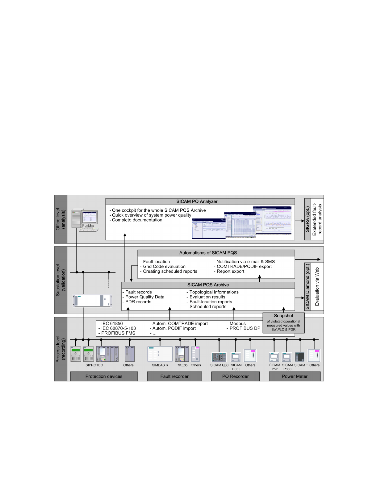
Introduction
1.4 Parameterization and Analysis Software
Structured representation and structured access to archive data
•
Cumulative summary of all PQ data in a state criterion (PQ index)
•
Spatially distributed options for the monitoring and evaluation of PQ measured data
•
Archiving of PQ data (measured values, fault records, PDR records)
•
Different communication standards and interfaces for device connection and for the acquisition of
•
process data (Ethernet TCP/IP, serial interfaces)
Automatic import from third-party devices in PQDIF and COMTRADE format
•
Ethernet network monitoring, for example, based on SNMP
•
Data exchange via OPC for the connection to office desktop computers
•
Secured data access via a user management
•
Redundant structure of the system on different levels
•
Test and diagnostic functions
•
Export of fault records via COMTRADE
•
Export of PQ data via PQDIF
•
Notification via e-mail and SMS
•
[dw7keebe-161012-01.tif, 2, en_US]
Figure 1-1
Architecture
SICAM PQS is suitable for varied use in energy supply or industrial facilities due to its modular system struc-
ture.
26 SIPROTEC 5, Fault Recorder, Manual
Overview of the Advantages of SICAM PQS
C53000-G5040-C018-5, Edition 11.2017
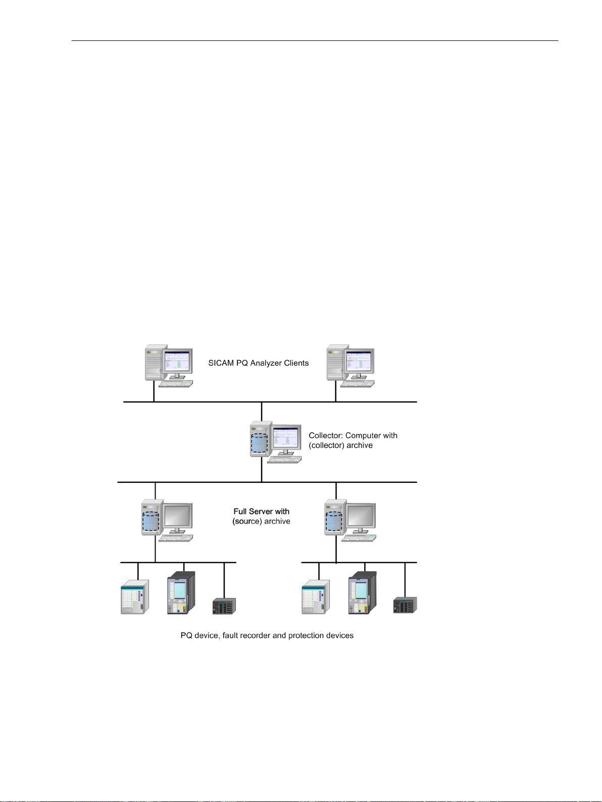
Thus, SICAM PQS can be set up in different variants:
Full Server with (source) archive and SICAM PQ Analyzer
•
System with
•
– Full servers with (Source) archive
– SICAM PQ Analyzer Clients
System with
•
– Full servers
– Archive computers with (Collector) archive
– SICAM PQ Analyzer Clients
The number of components which can be used in a system depends on the individual license.
(Source) Archive
The Full Server collects PQ measured data and fault records from connected devices and stores them in its
local (source) archive. This archive data can be directly evaluated by one or several SICAM PQ Analyzer(s).
(Collector) Archive
In distributed systems with one or several Full Servers, the data in the (source) archives is collected by the
SICAM PQ Analyzer Collector and stored in a central (Collector) archive on an archive computer. This archive
data is evaluated by one or more SICAM PQ Analyzer(s).
Introduction
1.4 Parameterization and Analysis Software
[dwcollec-151012-01.tif, 1, en_US]
Figure 1-2
SIPROTEC 5, Fault Recorder, Manual 27
C53000-G5040-C018-5, Edition 11.2017
Configuration Options with SICAM PQS System with Full Servers, SICAM PQ Analyzer Clients
and (Collector) Archive

Introduction
1.5 Scope of Functions
1.5
Registration Systems in Power Plants
Scope of Functions
In power plants, it is essential that the following problems be analyzed and evaluated and, if necessary,
counter measures implemented:
There is a short circuit on the generator during the startup phase, before the generator has reached the
•
rated frequency of the power-system voltage. During this time range, the generator frequency passes
through a range of 0 Hz to the rated value f
The circuit breaker of the generator closes. In this time range, possible errors, such as incorrect phase
•
sequence or insufficient synchronization, must be registered. Use of the Fast-scan recorder is necessary
in this case, too.
There is a short circuit on the generator or in the transmission system, after the generator was coupled
•
with the electrical power system and ran without interruption. Use of the function Fast-scan recorder is
helpful in this case, too. The cause of the short circuit on the generator can be analyzed with the recordings.
Local or entire system power swings occur. These oscillations can severely stress the generator shaft, if,
•
for example, the use of electronic restraint measures (Power System Stabilizer (PSS)) is not provided or
the calibration of the electronics is faulty. These failures can be recorded precisely with the functions
Slow-scan recorder and Continuous recorder. The process quantities (power, frequency, RMS values of
the fundamental component of currents and voltages and of symmetric components) form a special
characteristic with which the electronic signals of the PSS and other important quantities, such as the
excitation current of the generator, the steam pressure etc., can be recorded. Finally, these signals can be
compared and evaluated with the history of the RMS value of the voltage and the current.
. Use of the Fast-scan recorder is necessary in this phase.
rated
Power swing cycles between the power plant and transmission system can lead to severe damage to the
•
generator if they are not detected in time and shut down. This job is performed by the distance protection equipment. With the use of the Slow-scan recorder function, the network status can be precisely
recorded before, during and after the power swing cycle. If, in parallel to this, the function is activated, it
is possible to clarify, for example, whether a closer or more distant short circuit in the network was the
cause for the trip of this power swing, or load or generator shedding which put the network in this state.
The Phasor Measurement Unit (PMU) function is used for monitoring large transmission systems. With
•
this, the phasors of the power-system voltage, the line current and the power frequency are calculated
precisely and provided with a time stamp. The calculated data are sent continuously to a computer via a
communication channel, the Phasor-Data Concentrator (PDC). The data of several PMUs are processed
and evaluated in the PDC so that bottlenecks in the transmission system, line overloads, etc., can be
determined.
The Continuous recorder function is used to examine the long-term stability of power-system voltage
•
and power frequency. With these registration functions, the long-term history of the currents and
voltages, the active and reactive power, the power frequency and other important network variables can
be recorded. With the use of the Continuous recorder registration function, it is possible to adapt the
recordings to be more comprehensive and informative.
As described previously, through the use of a modern fault recorder and proper use of the corresponding functions, the electrical events in and around the power plant can be recorded precisely and then analyzed.
28 SIPROTEC 5, Fault Recorder, Manual
C53000-G5040-C018-5, Edition 11.2017

Registration Systems in the Transmission Systems
Most fault recorders are installed in the switchgears for transmission systems. Even though the main application area is still post-mortem analysis and thus the use of the Fast-scan recorder function, the use of other
functions to understand stability problems in the energy network and take the appropriate counter measures
is growing.
Capacitor voltage dividers are used in several transmission systems. In the case of a short circuit in the
•
line, high-frequency fault signals can occur in the voltage map, which then lead to over or under function
of protection devices. With the use of the function Fast-scan recorder, these transient processes, as well
as the behavior of the protection devices can be extensively analyzed.
Common-mode reactors at the beginning and end of transmission lines form a resonant circuit with the
•
line capacity and /or with a longitudinal condenser. If a line is shut off, then resonant oscillations can
exist, which last several network periods. For 1-pole short interruptions, these oscillations of the measured values of protection devices can be significantly corrupted and thus cause unwanted tripping. For
this reason the resonant oscillations must be recorded and analyzed after switching off the lines with the
function Fast-scan recorder.
Inductance of voltage transformers and scatter capacities in switchgears (busbars, lines) can lead to
•
ferroresonance effects. These problems are not registered under normal conditions of protection devices.
If these problems are not detected and counter measures implemented in a timely manner, significant
damage can result in the switchgear, such as the explosion of voltage transformers. For registration of
these processes, the function Fast-scan recorder is necessary.
Measurements over large areas of the transmission system (Wide Area Monitoring) can be performed
•
with the functions Slow-scan recorder and Phasor Measurement Unit (PMU). The objective of the
measurements is the detection of power fluctuations and power swing cycles as well as voltage and
frequency stability problems.
Introduction
1.5 Scope of Functions
Increasingly, the use of continuous recorders is growing. With these functions, the long-term stability
•
problems can be analyzed in detail. These measurements form a solid foundation for expensive investments such as the procurement of compensation systems (SVC).
The availability and quality of the power supply is very important for power distribution utilities. To
•
monitor the voltage quality (also known as Power Quality (PQ)) over a long period of time, the Trend
recorder function must be used. With this function, the long-term behavior of voltages (fluctuations in
frequency, voltage, short-term voltage changes, transients, signal distortions, etc.) can be precisely
recorded. Using the Trend recorder function contributes to a high-quality and reliable energy supply. An
analysis according to EN 50160 can be mapped using the averaged values (frequency: 10 s; short-term
flicker strength over 10 minutes and long-term flicker strength over 2 hours).
Registration Systems in HVDC Switchgear
The use of modern registration systems in high-voltage DC transmission systems (HVDC) is significantly
different than the use in transmission systems or power plants.
The use of the classic function Fast-scan recorder is thus very important in connection with the process signal
inputs. With this constellation, it is possible to register alternating and direct-voltage variables together. In
some cases, it is additionally desired to register gate trigger pulses for thyristors via binary channels. Areas of
use are, for example, Flexible Alternating-Current Transmission Systems (FACTS) and thyristor-driven reactivepower compensation systems.
In the future, it can be expected that, in HVDC and FACTS systems, the use of the functions Slow-scan
recorder, Continuous recorder and Phasor Measurement Unit (PMU) will increase to monitor the function
groups of the system for stability control of the network and to register faults.
Registration Systems in Distribution Systems and Industrial Complexes
Modern registration systems are used in important transformer stations where the transition from transmission to distribution takes place. Such transformer stations are present both in the power utility area as well as
in industrial complexes. The most important function is here the Fast-scan recorder for registering short
circuits.
SIPROTEC 5, Fault Recorder, Manual 29
C53000-G5040-C018-5, Edition 11.2017
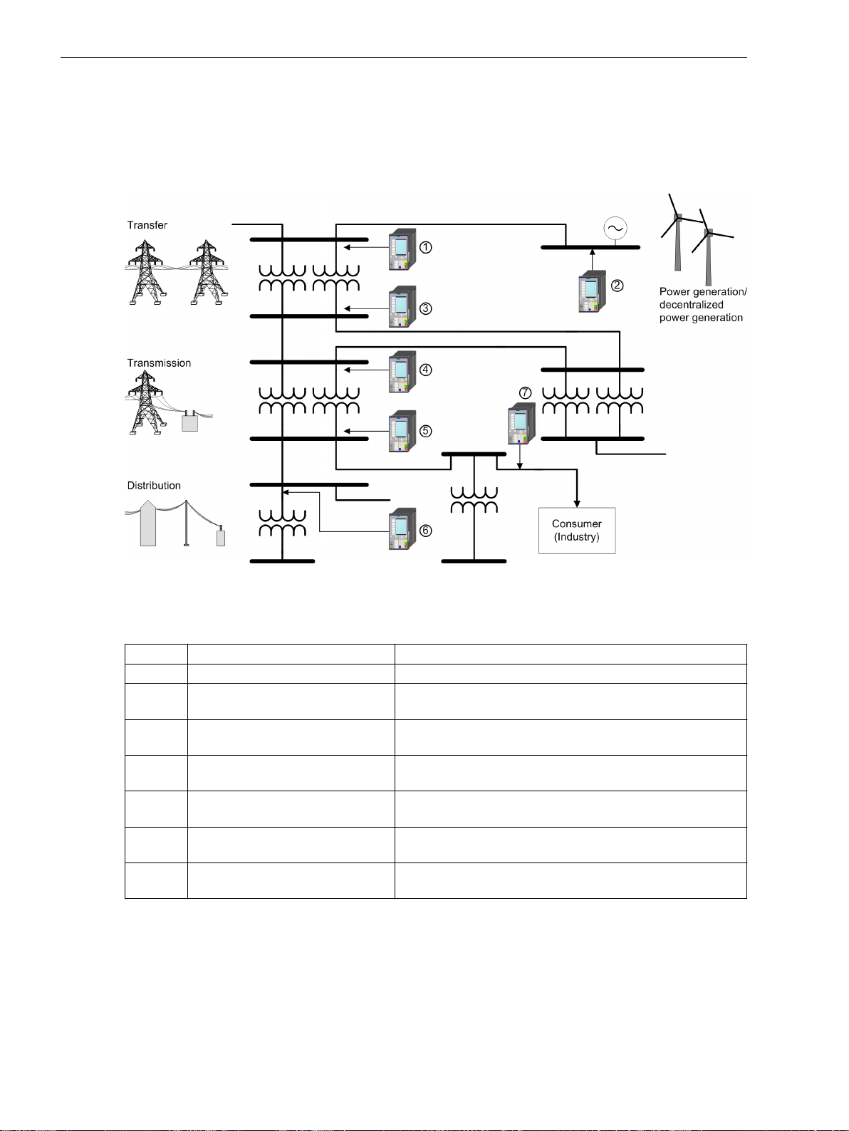
Introduction
1.5 Scope of Functions
Identifying the Measuring Points
The measuring points can be assigned and established for example as in the Figure 1-3. The fault record or PQ
data acquisition requires, in addition to the selection of the measuring point, also a definition and establishment of the evaluation criteria at the individual measuring points. There the monitoring of the Network
Quality is a combination of data acquisition techniques, which are classified according to purpose or use.
[dwnetzve-161012-01.tif, 1, en_US]
Figure 1-3
General Display of the Measuring Points
Table 1-1 Assignment of measuring points
No. Measuring Points Location
1 Infeed (line or transformer) Possible busbars
2 Power generation/decentral power
Busbars, transformers or generator connection
generation
3 Forwarding, distribution system Busbars (for example, if the busbar belongs to the transmis-
sion company and is run by it.)
4 Forwarding, infeed (line or trans-
former)
Decentral line connection (for example, if the line belongs to
the transmission company and is run by it.)
5 Forwarding, distribution system Transformer secondary circuit or cable for adjacent trans-
former station
6 Distribution, infeed (line or trans-
Distribution transformer
former)
7 Power distribution, consumers Distribution transformers (for example, if the transformer
belongs to the transmission company and is run by it.)
30 SIPROTEC 5, Fault Recorder, Manual
C53000-G5040-C018-5, Edition 11.2017
 Loading...