

Page 1
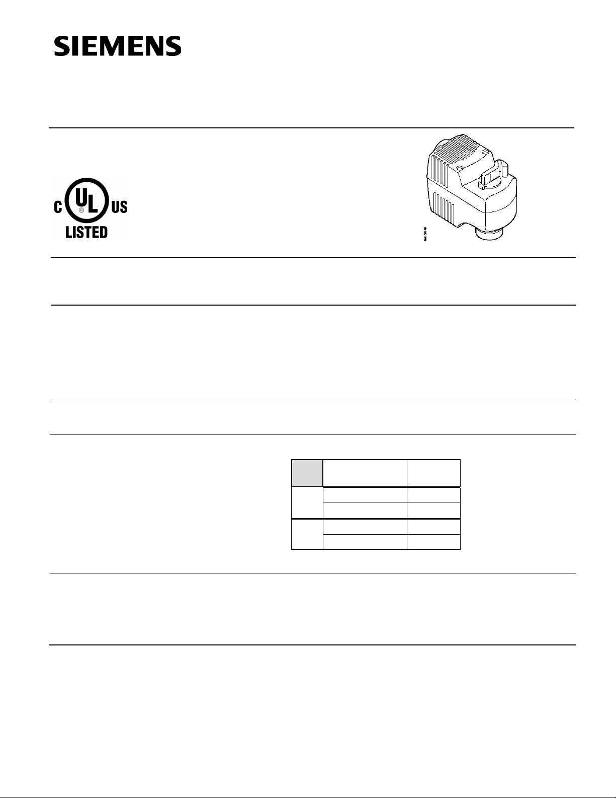
599 Series
Zone Valve Actuator
SF Series Electronic
Valve Actuator, 2-position Control
Technical Instructions
Document No. 155-321P25
August 8, 2017
Description
Features
Application
Product Number
The 599 SF Series electronic zone valve actuators, accepts 24 Vac or 120 Vac power
supply signal to provi de two-position control. This actuator works with Siemens 599
Series zone valves with 1/10-inch ( 2. 5 mm) str oke.
• UL listed for plenum installations
• Direct coupled installation without tools
• Manual override
• Visual position indication
• Spring return fail-safe operation
For use in heati ng and cooling HVAC applicati ons with Siemens 599 Series Zone
Valves that need 24 lb (105N) nominal force.
Tabl e 1.
Actuator
Product Number
SFP71U 24 Vac
NO
SFP11U 120 Vac
SFA71U 24 Vac
NC
SFA11U 120 Vac
Power
Supply
Orderi ng
Information
* Actuator wit h 2.5-meter c able only; not available as an assembly.
To order a com plete valve plus actuator assembly from the factory, com bine the
actuator prefix code with the suffix of the valve product number. See Technical Bulletin
TB254 (155-291) for selection procedures.
To order a single actuator, use the part number (f or example, SFA11U).
Siemens Industry, Inc.
Page 2
Technical Instructions 599 Series Zone Valve Actuator
Document No. 155-321P25 SF Series Electronic Valve Actuator
August 8, 2017 2-position Contr ol
Warning/Caution Notations
Specifications
Power supply
Function
Agency certification
Ambient conditions
Miscellan eous
WARNING:
CAUTION:
Frequency 50/60 Hz 60 Hz
Power consumption 9.8 VA 9.8 VA
Running time 10 seconds
Nominal stroke 1/10-inch (2.5 mm)
Nominal force 24 lb (105Nm)
Operation
Temperature 41°F to 122°F (5°C to 50°C)
Humidity 0% to 90% rh (non-condensing)
Transport and storage
Temperature –13°F to 158°F (–25°C to 70°C)
Humidity 0% to 90% rh (non-condensing)
Mounting l ocation NEMA 1 (interior only)
Noise <35 db
Medium temperature 34°F to 230°F (1°C to 110°C)
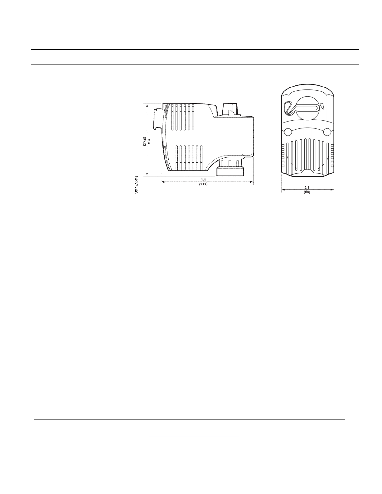
Dimensions- I nches (mm) 3.4 (85.2) H × 4.4 (111) W × 2.3 (58) D
Weight 1.18 lb (0.54 kg)
Personal inj ury or loss of life m ay occur if you do not perf orm
a procedure as specified.
Equipment damage may occur if you do not perf orm a
procedure as specified.
24 Vac 120 Vac
UL listed to UL873
cUL certified to Canadian Standard
C22.2 No. 24-93
Operation
Page 2 Siemens Industry, Inc.
A 24 Vac or 120 Vac cont rol signal drives the act uator from its norm al
(0 voltage) position.
In the event of power l oss, the actuator will return to it s normal ext ended posi tion for the
SFA model actuators or normal retrac ted position for the SFP models.
CAUTION:
When sel ecting a heati ng or cooling on/off zone valve that must be closed for
long periods of tim e or an entire season, use a Normally Closed actuator (such as
the SFA71U Actuator) f or new or replacement applications.
If t he valve needs to be open f or extended peri ods of tim e or an entire season,
use a Normall y Open actuator (such as the SFP71U Actuator) for new or
replacem ent applicat ions.
SFP Actuators should not be used on hot water systems that remain operational
all year long or where actuators are continually c ommanded closed during the
summer.
Page 3
599 Series Zone Valve Actuator Technical Instructions
SF Series Electronic Valve Actuator Document No. 155-321P25
2-position Contr ol August 8, 2017
Mounting and
Installation
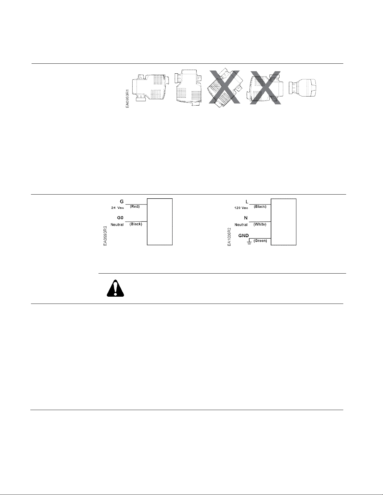
Figure 1. Mounting Position.
• Mount t he act uator in one of the allowable positions shown in F igure 1.
• W hen m ounting the actuator in a pl enum, the proper cabl e must be attached
to meet local codes.
• All ow 8 inches (200 m m) abov e the actuator and 8 i nches (200 m m) behi nd
the cable for service.
• Installation Instructions are included with the actuator.
Wiring
Figure 2.
24 Vac Wiring Diagram.
WARNING:
Wire connecti on, G is Hot, not ground.
• Do not use autotransformers.
• Use earth-ground isolating, step-down, Class 2, power supplies.
• Determi ne supply transf ormer rating by summ ing tot al VA of al l actuat ors
used.
• SF A71U/SFP71U 24 Vac actuators: W iring connection i s inside the actuator
housing (remove housing top for access). The act uat or lead length is 10
inches (254 mm).
• SFA11U/SFP11U 120 Vac actuators: W iring connection requires junction box
and flex conduit no further than 15 inches (381 mm ) from the actuator. The
actuator l ead length is 18 inches (457 mm).
NOTE: One transformer should power no more than 10 actuators.
120 Vac Wring Diagram.
Figure 3.
Siemens Industry, Inc. Page 3
Page 4
Technical Instructions 599 Series Zone Valve Actuator
Document No. 155-321P25 SF Series Electronic Valve Actuator
August 8, 2017 2-position Contr ol
Manual
Override
Start-Up
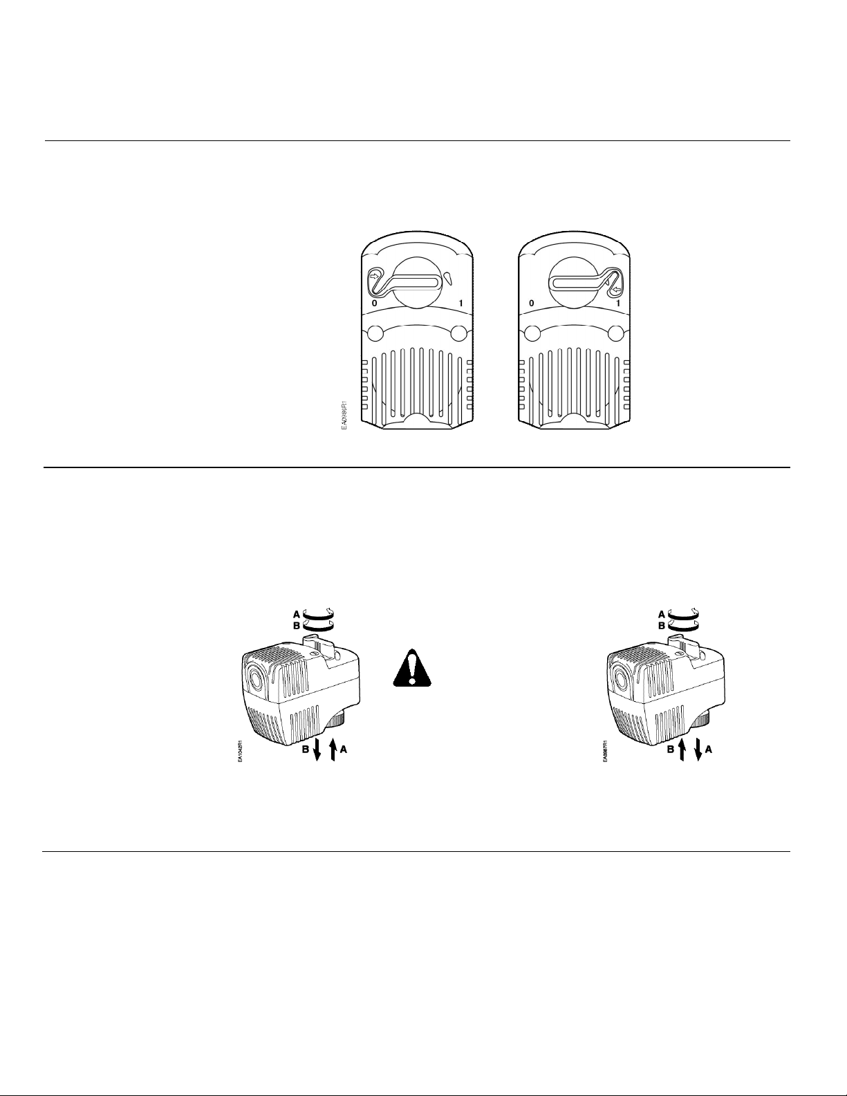
For manual positioni ng, simply turn the manual overr ide handle to the protruding stop and
squeeze the handle to l atch and hold its posit ion.
The actuator will maintain i t s posit ion until power i s provided.
NOTE:
The 0 and 1 position
indicators are intended
for reference only, and
not for stroke
measurement.
Figure 4. Manual Override Handle Positioning.
Check the wiring and the position i ndication.
When the position i ndicator is in the 0 position:
SFP: The output shaft will be retracted; the actuator is Normall y Open. See Fi gure 5.
SFA: The output shaft will be ext ended; the actuator is Normall y Closed. See Figure 6.
When the position i ndicator is in the 1 position, the reverse is true.
CAUTION:
Avoid damage to
actuator; DO NOT
manually assi st
spring return.
(A) Allow handle to turn counterclockwise to retract spindle.
(B) Turn handle clockwise to extend spindle.
Figure 5. SFP Models, Normally Open.
(A) Allow handle to turn counterclockwise to extend spindle.
(B) Turn handle clockwise to re tract spindle.
Figure 6. SFA Models, Normally Closed.
Page 4 Siemens Industry, Inc.
Page 5
599 Series Zone Valve Actuator Technical Instructions
SF Series Electronic Valve Actuator Document No. 155-321P25
2-position Contr ol August 8, 2017
Troubleshooting
Service Kits
Dimensions
Inches (Mil limeters)
Service Envelope
See Wiring for proper connections.
If t he actuator is inoperative, replace t he unit.
Figure 7. Dimensions of the SF x Series Actuator.
Minimum access space recommended:
8 inches (200 mm) abov e the actuator and beside t he terminal plug.
Information in this publication is based on current specifications. The compa ny reserves the right to make changes in specifications and models as
design improvements are introduced. Product or company names mentioned herein may be the trademarks of their respective owners.
© 2017 Siemens Industry, Inc.
Siemens Industry, Inc.
Building Technologies Division
1000 Deerfield Parkway
Buffalo Grove, IL 60089
USA
+ 1 847-215-1000
Your feedback is important to us. If you hav e comments
about this document, please send them to
Document No. 155-321P25
Printed in the USA
Page 5
 Loading...