

Siemens Series 2300 Installation Instructions Manual
Series 2300 Room Units
for TALON® Controllers
Product Description
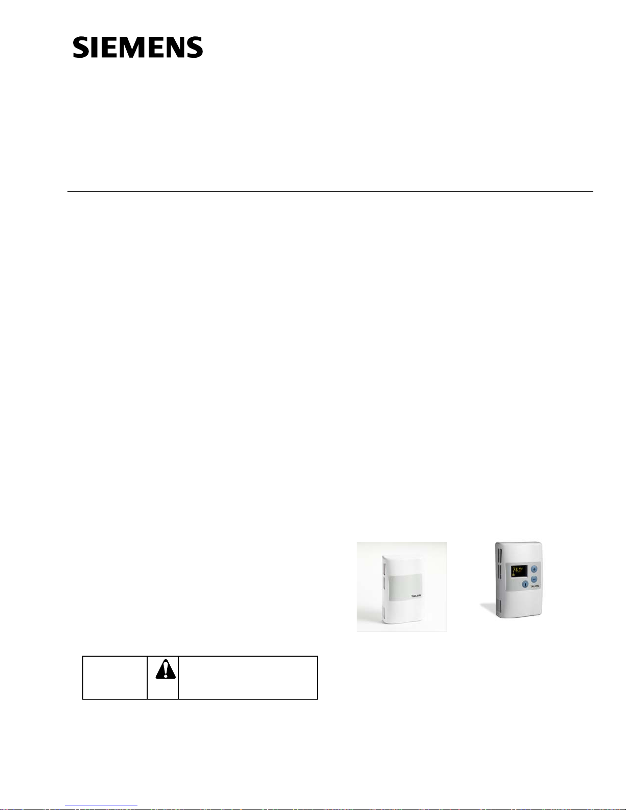
These room units measure temperature in the
occupied space in which they are installed. Models
with display allow users to view the measured
temperature value. A version with temperature
setpoint adjustment is also offered.
These devices are intended for use with appropriate
signal input on a TALON Controller. The effective
sensing and setpoint range is 55°F to 95°F (13°C to
35°C).
These room units can be mounted on electrical
boxes, stud-type mounting brackets, or drywall.
Obtain the necessary mounting hardware and follow
the appropriate mounting procedures for the type of
installation required.
Installation Instructions
Document No. 129-479
November 13, 2012
Expected Installation Time
20 minutes
Required Tools
• Sizes 1 and 2 Phillips screwdrivers
• Small and medium flat-blade screwdrivers
• 1/16-inch hex key
• Medium-duty electric drill
• 3/16-inch (4.8 mm) drill bit
• One-inch (25 mm) hole saw
• Small level
• Tape measure
• Marker or pencil
Product Numbers
QAA2312.xWxN
QAA2330.xWxx
QAA23SS.xWxN
QAA23SS.xWxx
Accessories
AQA2200-INTL Room Unit Back Plate (10-pack)
AQA2200-2X4 Room Unit Back Plate (Single)
NOTE: If installing the Back Plate, discard the
metric screws provided with the Back Plate
and utilize the Room Unit mounting screws.
Caution Notations
CAUTION
Equipment damage or loss of
data may occur if you do not
follow a procedure as
specified.
Prerequisites
• Review these instructions before beginning.
• Installed: appropriate field wiring within the
maximum wiring run length for the individual
equipment controller. The maximum
recommended length is 100 feet (30 m).
• All wiring must comply with National Electric
Code (NEC) and local regulations.
Figure 1. QAA23xx.EWTN, and QAA23xx.FWTN
Room Units.
Item Number 129-479, Rev. HA
Page 1 of 6
Document No. 129-479
Installation Instructions
November 13, 2012
Mounting Information
Always mount the room unit vertically.
Locate the room unit:
• according to design specifications and local
regulations.
• where the air circulates around it freely (not
in recessed areas or behind doors).
• allowing a minimum of 4 inches (10 cm) free
space above and below for proper airflow,
the front cover removal tool, and the
computer communication cable.
• away from drafts caused by doors, windows,
outside walls, air registers, pipes, return air
plenums, etc.
• away from heat sources such as strong
lights, fireplaces, direct sunlight, etc.
• on an inside wall (preferably), about 5 feet
(1.5 m) above the finished floor.
Drywall Mounting (No Rough-in),
Typical
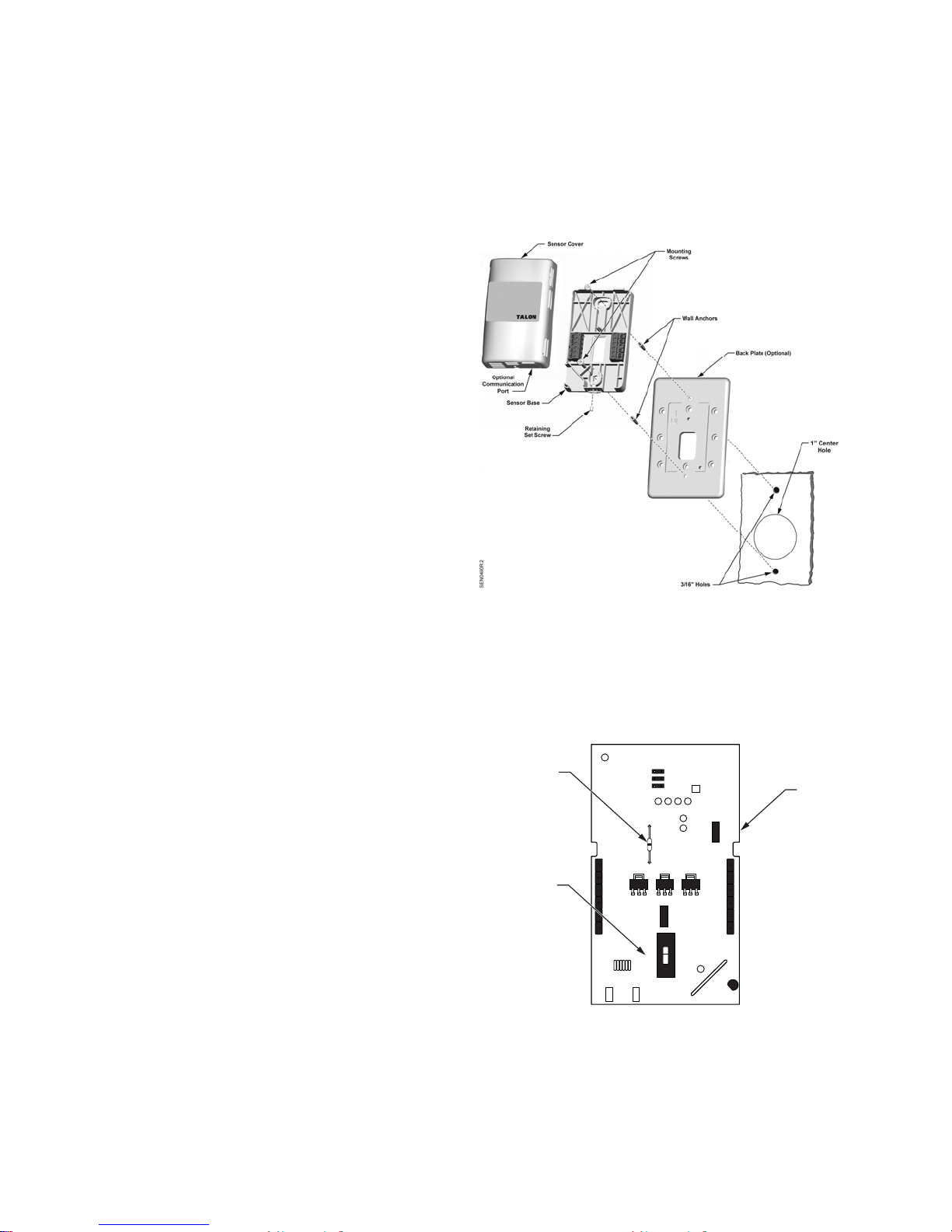
Base Plate Mounting and Wiring
1. Mark the center (cable) hole and the mounting
hole locations, using the room unit base plate as
a template. See Figure 2.
2. Drill two 3/16-inch (4.8 mm) mounting holes and
mount the two plastic wall anchors flush to
below the wall surface for stable mounting of the
device.
3. Cut a 1-inch (25 mm) center hole with a hole
saw.
4. Pull about three inches (75 mm) of the cable
through the hole in the base plate.
5. Mount the room unit base plate on the wall,
noting the UP arrow:
NOTE: If required, position the Back Plate
behind the Room Unit Base, aligning
the top and bottom mounting holes,
prior to mounting to the wall:
d. Cut the cable, leaving about three inches
(75 mm) on the room unit side of the
drywall. Ensure that pin Number 1 connects
to the same wire at each end of the cable.
Figure 2. Drywall Mounting (No Rough-in), Typical.
7. Terminate the wires to the termination blocks on
the room unit's base plate. (See
Figure 5.)
8. Feed the extra cable back through the hole.
Sensor Set-up
R64 Resistor
(°F/°C Selector)
Jumper
5V
10V
Voltage/Current
Selector Switch
V
I
SEN0589R1
a. Install the two mounting screws provided,
but do not tighten.
b. Level the room unit base plate for
appearance.
c. Tighten the two mounting screws to the
room unit base plate.
Page 2 of 6 Siemens Industry, Inc.
Figure 3. Circuit Board
(Located inside Room Unit Cover.
 Loading...