

Siemens SENTRON Series Product Manual
Product Manual
Manual Module I(N), I(Diff), Analog
Measuring Devices 7KM
04/2017Edition
SENTRON
siemens.com/lowvoltage
Margin Margin
Bufferzone
blue dark 100 % Stone gray 100%
Siemens Sans, Roman,
36/30/26 pt, white
Absatzformat: 01 System
Siemens Sans, Roman,
13/12/11 pt, white
Absatzformat: 03 Titel
Siemens Sans, Bold,
11/12/13 pt, white
Absatzformat: 04 Dokuklasse
Wird mehr Text verwendet
Verlaufsfeld nach oben
erweitern. Abstände von
Rand zu Text einhalten!
Siemens Sans, Bold,
9 pt, black
Absatzformat: 06 URL
2 x
Siemens Sans, Bold
18/16/14 pt, white
Absatzformat: 02 Produkt
Siemens Sans, Bold
11/9/7,5 pt, white
Absatzformat: 05 Ausgabe
1/10x
1/10x
1/10x
1/14x
1/10x
1/5x
1/5x
1/28x
1/20x
1/20x
1/5x
1/28x
1/20x
1/20x
1/20x
1 x
wenn möglich in gleicher Schriftgruppe bleiben!
groß
36
18
13
13
9
11
mittel
30
16
12
12
9
9
klein
26
14
11
11
9
7,5
System
Produktgruppe
Titel
Dokuklasse
URL
Ausgabe
Titelseite OHNE Beschnitt in RGB
Alle Schriften sind als Absatzformat hinterlegt!!!


_
_________________
_
_
_________________
_
_
_________________
_
_
_________________
_
_
_________________
_
_
_________________
_
_
_________________
_
_
_________________
_
SENTRON
7KM measuring device
Expansion module I(N), I(Diff),
analog
Manual
04/2017
L1V30408520AG-01
Introduction
1
Description
2
Mounting
3
Connection
4
Commissioning
5
Service and maintenance
6
Technical data
7
A
ppendix
A
Siemens AG
Division Energy Management
Postfach 32 20
91050 ERLANGEN
GERMANY
Document order number: 3ZW1012-7KM02-0AC1
Ⓟ 03/2017 Subject to change
Copyright © Siemens AG 2017.
All rights reserved
Legal information
Warning notice system
This manual contains notices you have to observe in order to ensure your personal safety, as well as to prevent
damage to property. The notices referring to your personal safety are highlighted in the manual by a safety alert
symbol, notices referring only to property damage have no safety alert symbol. These notices shown below are
graded according to the degree of danger.
DANGER
indicates that death or severe personal injury will result if proper precautions are not taken.
WARNING
indicates that death or severe personal injury may result if proper precautions are not taken.
CAUTION
indicates that minor personal injury can result if proper precautions are not taken.
NOTICE
indicates that property damage can result if proper precautions are not taken.
If more than one degree of danger is present, the warning notice representing the highest degree of danger will
be used. A notice warning of injury to persons with a safety alert symbol may also include a warning relating to
property damage.
Qualified Personnel
The product/system described in this documentation may be operated only by personnel qualified for the specific
task in accordance with the relevant documentation, in particular its warning notices and safety instructions.
Qualified personnel are those who, based on their training and experience, are capable of identifying risks and
avoiding potential hazards when working with these products/systems.
Proper use of Siemens products
Note the following:
WARNING
Siemens products may only be used for the applications described in the catalog and in the relevant technical
documentation. If products and components from other manufacturers are used, these must be recommended
or approved by Siemens. Proper transport, storage, installation, assembly, commissioning, operation and
maintenance are required to ensure that the products operate safely and without any problems. The permissible
ambient conditions must be complied with. The information in the relevant documentation must be observed.
Trademarks
All names identified by ® are registered trademarks of Siemens AG. The remaining trademarks in this publication
may be trademarks whose use by third parties for their own purposes could violate the rights of the owner.
Disclaimer of Liability
We have reviewed the contents of this publication to ensure consistency with the hardware and software
described. Since variance cannot be precluded entirely, we cannot guarantee full consistency. However, the
information in this publication is reviewed regularly and any necessary corrections are included in subsequent
editions.

Expansion module I(N), I(Diff), analog
Manual, 04/2017, L1V30408520AG-01
5
Table of contents
1 Introduction ................................................................................................................................................ 7
1.1
Scope of delivery ...................................................................................................................... 7
1.2
Latest information ..................................................................................................................... 7
2
Description ............................................................................................................................................... 11
2.1
Area of application .................................................................................................................. 11
2.2
Performance features of the I(N), I(Diff), analog module ........................................................ 11
2.3
Design ..................................................................................................................................... 12
3
Mounting .................................................................................................................................................. 15
3.1
Warning ................................................................................................................................... 15
3.2
Installation location ................................................................................................................. 15
3.3
Installation steps ..................................................................................................................... 15
4
Connection .............................................................................................................................................. 17
4.1
Safety information ................................................................................................................... 17
4.2
Connections ............................................................................................................................ 19
5
Commissioning ........................................................................................................................................ 23
5.1
Overview ................................................................................................................................. 23
5.2
Setting the expansion module parameters ............................................................................. 24
5.3
Reading out measured values ................................................................................................ 27
6
Service and maintenance ........................................................................................................................ 29
6.1
Calibration ............................................................................................................................... 29
6.2
Firmware update ..................................................................................................................... 29
6.3
Troubleshooting guide ............................................................................................................ 29
6.4
Warranty ................................................................................................................................. 30
6.5
Disposal .................................................................................................................................. 30
7
Technical data ......................................................................................................................................... 31
7.1
Technical specifications .......................................................................................................... 31
A
Appendix .................................................................................................................................................. 35
A.1
Modbus measured variables with function codes 0 x 03 and 0 x 04 ...................................... 35
Index ........................................................................................................................................................ 37


Expansion module I(N), I(Diff), analog
Manual, 04/2017, L1V30408520AG-01
7
Introduction
1
1.1 Scope of delivery
Included in package:
● 1 x 7KM PAC expansion module I(N), I(Diff), analog
● 1 x operating instructions
1.2 Latest information
Up-to-the-minute information
You can find further support on the Internet:
Website (https://support.industry.siemens
.com/my/ww/en/requests)
Information about third-party software
This product, solution or service ("product") includes the third-party software components
listed below. This is either open source software that is licensed under a license approved by
the Open Source Initiative (www.opensource.org (https://opensource.org/)), or u
nder a
license ("OSS") defined as comparable by Siemens, and/or it is commercial software or
freeware. With regard to the OSS components, the relevant OSS license conditions take
precedence over all other conditions applicable to this product. SIEMENS makes the OSS
components of this product available to you at no extra cost.
Insofar as SIEMENS has combined or linked certain components of the product with OSS
components according to the definition of the applicable license, i.e. components that are
licensed under GNU LGPL Version 2 or a later version and insofar as use of the relevant
object file is subject to certain restrictions ("LGPL-licensed module" whereby the LGPLlicensed module and the components to which the LGPL-licensed module is linked are
referred to hereafter as "linked product") and the relevant LGPL license criteria are met, you
are also permitted to i) modify the linked product for your own purposes and, in particular,
you have the right to modify the linked product in order to link it to a modified version of the
LGPL-licensed module, and to (ii) reverse-engineer the linked product, but solely for the
purpose of debugging your own modifications. The right to make modifications does not
include the right to distribute them. All information that you obtain from reverse-engineering
the linked product must be treated confidentially.
Certain OSS licenses oblige SIEMENS to publish the source code, e.g. the GNU General
Public License, the GNU Lesser General Public License and the Mozilla Public License.
Where these licenses are used and the product has not already been shipped with the
required source code, a copy of the source code can be requested by anyone during the
period specified in the applicable OSS license from the following address:

Introduction
1.2 Latest information
Expansion module I(N), I(Diff), analog
8 Manual, 04/2017, L1V30408520AG-01
Siemens AG
Energy Management, Low Voltage & Products
Siemensstrasse 10
93055 Regensburg
Germany
Internet : Technical assistance (https://support.industry.siemens.com/My/ww/en/
requests)
Subject: Open source request (please state product name and version, as applicable)
SIEMENS can charge a fee of up to 5 euros for processing the request.
Warranty with respect to use of open source software
The warranty obligations of SIEMENS are governed by the terms of the contract with
SIEMENS. Modification of the product or the OSS components or use of them for a purpose
other than the purpose specified by SIEMENS shall exclude them from the warranty in which
case you will no longer have the right to technical support. The following license conditions
may include limitations of liability that shall apply between you and the respective licensor.
To avoid any misunderstanding, we hereby emphasize that SIEMENS shall not enter into
any warranty obligations in the name of or binding on a third-party licensor.

Introduction
1.2 Latest information
Expansion module I(N), I(Diff), analog
Manual, 04/2017, L1V30408520AG-01
9
Safety information
Siemens provides products and solutions with industrial security functions that support the
secure operation of plants, systems, machines, and networks.
In order to protect plants, systems, machines and networks against cyber threats, it is
necessary to implement – and continuously maintain – a holistic, state-of-the-art industrial
security concept. Siemens’ products and solutions only form one element of such a concept.
The customer is responsible for preventing unauthorized access to its plants, systems,
machines and networks. Systems, machines and components should only be connected to
the enterprise network or the Internet if necessary and only to the extent necessary and with
appropriate protective measures (e.g. use of firewalls and network segmentation) in place.
Additionally, Siemens' guidelines on appropriate security measures should be observed. For
more information about industrial security, please visit
Industrial security (http://www.siemens.com/industrialsecurity)
Siemens’ products and solutions undergo continuous development to make them more
secure. Siemens strongly recommends applying product updates as soon as they are
available and always using the latest product versions. Using versions that are obsolete or
are no longer supported can increase the risk of cyber threats.
To stay informed about product updates, subscribe to the Siemens Industrial Security RSS
Feed at
Siemens Industrial Security RSS Feed (http://www.siemens.com/industrialsecurity).
General safety information
DANGER
Danger! High voltage
Will cause death or serious injury.
Turn off and lock out all power supplying this device before working on it.


Expansion module I(N), I(Diff), analog
Manual, 04/2017, L1V30408520AG-01
11
Description
2
2.1 Area of application
The expansion module has been designed for use in combination with the 7KM PAC devices
PAC3200 and PAC4200. The guidelines for the 7KM PAC devices also apply to the
expansion modules.
2.2 Performance features of the I(N), I(Diff), analog module
The expansion module I(N), I(Diff), analog increases the scope of measuring functions of the
PAC3200 / PAC4200 devices.
Overview:
● Plug-in expansion module for the SENTRON PAC3200 and PAC4200 measuring devices
● Measurement of N (neutral) conductor current through external current transformer
● Measurement of residual current and PE conductor current through external summation
current transformer
● Measurement of physical quantities with external 0 / 4 ... 20 mA transmitter
● Display of measured values directly on screen of PAC measuring device
● Status display via LED
Description
2.3 Design
Expansion module I(N), I(Diff), analog
12 Manual, 04/2017, L1V30408520AG-01
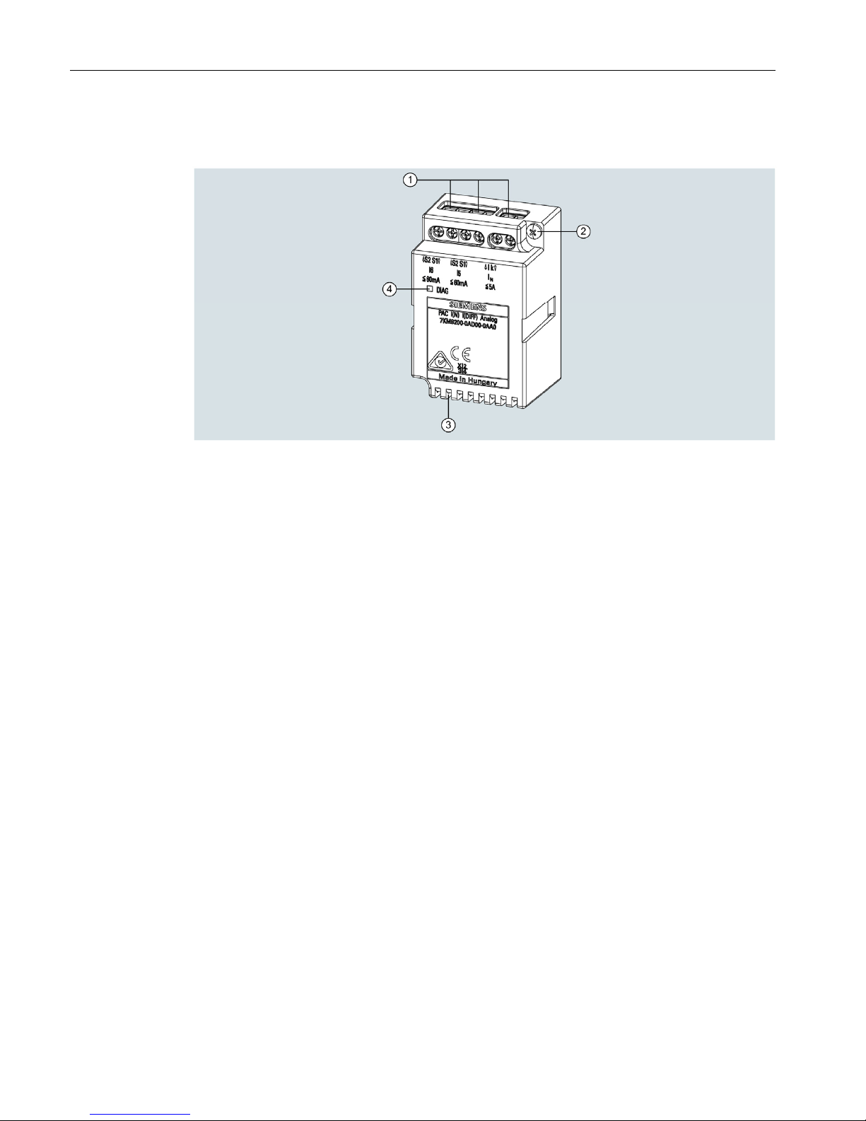
2.3 Design
(1) Screw terminals for connection of current transformer or sensor
(2) Screw for mounting the expansion module I(N), I(Diff), analog
(3) Ventilation slot
(4) Diagnostic LED
Figure 2-1 Schematic representation of expansion module I(N), I(Diff), analog
IN connection:
Current transformer connection for N-conductor current measurement 1 A / 5 A input
I
5
connection:
● 0 ... 20 mA analog input
● 4 ... 20 mA analog input
● 0 ... 60 mA RCM (Residual Current Monitoring)
I
6
connection:
● 0 ... 20 mA analog input
● 4 ... 20 mA analog input
● 0 ... 60 mA PE current
 Loading...