

Siemens SENTRON PAC RS485 User Manual

SENTRON
Expansion module
PAC RS485
Manual
Introduction
Safety notes
Description
Assembling
Parameter
assignment/Addressing
Configuration
Service and maintenance
1
2
3
4
5
6
7
Alarm, error, and system
messages
Troubleshooting/FAQs
Technical data
Dimension drawings
Application examples
Appendix
ESD guidelines
8
9
10
11
12
A
B
02/2008
A5E02091800B-01
List of abbreviations
C

Safety Guidelines
This manual contains notices you have to observe in order to ensure your personal safety, as well as to prevent
damage to property. The notices referring to your personal safety are highlighted in the manual by a safety alert
symbol, notices referring only to property damage have no safety alert symbol. These notices shown below are
graded according to the degree of danger.
DANGER
indicates that death or severe personal injury will result if proper precautions are not taken.
WARNING
indicates that death or severe personal injury may result if proper precautions are not taken.
CAUTION
with a safety alert symbol, indicates that minor personal injury can result if proper precautions are not taken.
CAUTION
without a safety alert symbol, indicates that property damage can result if proper precautions are not taken.
NOTICE
indicates that an unintended result or situation can occur if the corresponding information is not taken into
account.
If more than one degree of danger is present, the warning notice representing the highest degree of danger will
be used. A notice warning of injury to persons with a safety alert symbol may also include a warning relating to
property damage.
Qualified Personnel
The device/system may only be set up and used in conjunction with this documentation. Commissioning and
operation of a device/system may only be performed by qualified personnel. Within the context of the safety notes
in this documentation qualified persons are defined as persons who are authorized to commission, ground and
label devices, systems and circuits in accordance with established safety practices and standards.
Prescribed Usage
Note the following:
WARNING
This device may only be used for the applications described in the catalog or the technical description and only
in connection with devices or components from other manufacturers which have been approved or
recommended by Siemens. Correct, reliable operation of the product requires proper transport, storage,
positioning and assembly as well as careful operation and maintenance.
Trademarks
All names identified by ® are registered trademarks of the Siemens AG. The remaining trademarks in this
publication may be trademarks whose use by third parties for their own purposes could violate the rights of the
owner.
Disclaimer of Liability
We have reviewed the contents of this publication to ensure consistency with the hardware and software
described. Since variance cannot be precluded entirely, we cannot guarantee full consistency. However, the
information in this publication is reviewed regularly and any necessary corrections are included in subsequent
editions.
Siemens AG
Automation and Drives
Postfach 48 48
90327 NÜRNBERG
GERMANY
Ordernumber: A5E02091800B-01
Ⓟ 03/2008
Copyright © Siemens AG 2008.
Technical data subject to change

Table of contents
1 Introduction................................................................................................................................................ 7
1.1 Purpose of this document ..............................................................................................................7
1.2 Orientation aids..............................................................................................................................7
1.3 Scope of supply .............................................................................................................................8
1.4 Contents of the CD for the SENTRON PAC Power Monitoring Device.........................................8
1.5 Technical support...........................................................................................................................9
1.6 Further documentation.................................................................................................................10
2 Safety notes............................................................................................................................................. 11
2.1 Safety notes .................................................................................................................................11
3 Description............................................................................................................................................... 13
3.1 Area of application .......................................................................................................................13
3.2 Features.......................................................................................................................................13
3.3 Tasks............................................................................................................................................14
3.4 Structure.......................................................................................................................................15
3.5 Firmware ......................................................................................................................................16
3.6 Bus and master............................................................................................................................17
4 Assembling.............................................................................................................................................. 19
4.1 Procedure for installation and commissioning .............................................................................19
4.2 Unpacking ....................................................................................................................................20
4.3 Assembly......................................................................................................................................21
4.4 Connecting...................................................................................................................................23
4.5 Measures to be performed prior to start-up .................................................................................26
4.6 Disassembly.................................................................................................................................27
5 Parameter assignment/Addressing.......................................................................................................... 29
5.1 MODBUS RTU.............................................................................................................................29
5.1.1 Structure of the job message frame.............................................................................................29
5.1.2 Character frame ...........................................................................................................................30
5.1.3 Function codes.............................................................................................................................31
5.1.4 Exception codes...........................................................................................................................33
5.1.5 Modbus measured variables with the function codes 0x03 an
5.1.6
5.1.6.1 Structure - Digital input status and digital output status with the function codes 0x03 and
5.1.6.2 Structure - Device diagnostics and device status with the function codes 0x03 and 0x04 .........38
5.1.6.3 Structure - Limit values with function codes 0x03 and 0x04........................................................39
5.1.7 Modbus status parameters with the function code 0x02 .............................................................39
5.1.8 Modbus settings with the function codes 0x03, 0x04 and 0x10 ..................................................40
Structure.......................................................................................................................................38
0x04 .............................................................................................................................................38
d 0x04 .........................................33
PAC RS485
Manual, 02/2008, A5E02091800B-01
3

Table of contents
5.1.9 Modbus command parameters ................................................................................................... 51
5.1.10 MODBUS communication parameter with the function codes 0x03, 0x04 and 0x10................. 52
5.1.11 Modbus device information with the function codes 0x03, 0x04 and 0x10................................. 53
5.1.12 MODBUS standard device identification with the function code 0x2B ....................................... 55
5.1.13 Parameters and function codes supported by the broadcast commands................................... 55
6 Configuration ........................................................................................................................................... 57
6.1 Default settings ........................................................................................................................... 57
6.2 Changing the address................................................................................................................. 57
6.3 Configuration of the PAC RS485 expansion module on the SENTRON PAC3200 Power
Monitoring Device ....................................................................................................................... 58
7 Service and maintenance ........................................................................................................................ 61
7.1 Cleaning ...................................................................................................................................... 61
7.2 Repair.......................................................................................................................................... 62
7.3 Disposal....................................................................................................................................... 62
8 Alarm, error, and system messages ........................................................................................................ 63
8.1 Diagnostics concept .................................................................................................................... 63
8.2 Diagnostics LED.......................................................................................................................... 64
8.3 Initializing the module.................................................................................................................. 64
9 Troubleshooting/FAQs............................................................................................................................. 65
9.1 Power failure ............................................................................................................................... 65
10 Technical data ......................................................................................................................................... 67
10.1 Cable ........................................................................................................................................... 67
10.2 Standards .................................................................................................................................... 67
10.3 Technical data............................................................................................................................. 68
10.4 Communication interface ............................................................................................................ 70
10.5 Labeling....................................................................................................................................... 71
11 Dimension drawings ................................................................................................................................ 73
11.1 Dimension drawings.................................................................................................................... 73
12 Application examples.......................................................................................................
12.1
Examples of MODBUS communication ...................................................................................... 75
........................ 75
A Appendix.................................................................................................................................................. 79
A.1 Correction sheet.......................................................................................................................... 79
B ESD guidelines ........................................................................................................................................ 81
B.1 Electrostatic sensitive devices (ESD) ......................................................................................... 81
C List of abbreviations................................................................................................................................. 83
C.1 Abbreviations .............................................................................................................................. 83
Glossary .................................................................................................................................................. 85
Index........................................................................................................................................................ 89
PAC RS485
4 Manual, 02/2008, A5E02091800B-01

Table of contents
Tables
Table 1-1
Table 1-2 Online service and support ............................................................................................................9
Table 1-3 Technical Support........................................................................................................................10
Table 5-1 Structure of the message frame...................................................................................................29
Table 5-2 Supported function codes ............................................................................................................31
Table 5-3 MODBUS exception codes ..........................................................................................................33
Table 5-4 Available measured variables......................................................................................................34
Table 5-5 Structure - Status of the digital inputs and status of the digital outputs.......................................38
Table 5-6 Modbus offset 205, tab 2: Structure device status and device diagnostics.................................38
Table 5-7 Modbus Offset 203, Register 2: Limit Violations..........................................................................39
Table 5-8 Status parameters........................................................................................................................39
Table 5-9 Settings parameters.....................................................................................................................40
Table 5-10 Settings parameter for the digital input ........................................................................................41
Table 5-11 Settings parameter for the digital output......................................................................................41
Table 5-12 Settings parameter for language, phase labels and universal counters source..........................42
Table 5-13 Settings parameter for the display ...............................................................................................43
Table 5-14 Settings parameter for limit value 0 .............................................................................................43
Contacts in your region - worldwide...............................................................................................9
Table 5-15 Settings parameter for limit value 1 .............................................................................................44
Table 5-16 Settings parameter for limit value 2 .............................................................................................45
Table 5-17 Settings parameter for limit value 3 .............................................................................................47
Table 5-18 Settings parameter for limit value 4 .............................................................................................48
Table 5-19 Settings parameter for limit value 5 .............................................................................................49
Table 5-20 Command parameters .................................................................................................................51
Table 5-21 Communication parameters.........................................................................................................52
Table 5-22 I&M 0 parameter of the SENTRON PAC Power Monitoring Device with the function codes
0x03 and 0x04 .............................................................................................................................54
Table 5-23 I&M 1-4 parameters with the function codes 0x03, 0x04 and 0x10.............................................54
Table 5-24 I&M 0 parameter of the module in slot 1 with the function codes 0x03 and 0x04 .......................54
Table 5-25 MODBUS standard device identification parameters ..................................................................55
Table 5-26 Parameters supported by the broadcast commands...................................................................56
Table 6-1 Factory settings............................................................................................................................57
Table 6-2 Structure of the setting versions ..................................................................................................59
Table 6-3 Setting options .............................................................................................................................60
Table 6-4 Performance calculation ..............................................................................................................60
Table 8-1 Fault and status indication by the LED ........................................................................................64
Table 10-1 The device meets the following standards...................................................................................67
PAC RS485
Manual, 02/2008, A5E02091800B-01
5

Table of contents
Table 10-2 Mechanical data for the PAC RS485 expansion module............................................................ 68
Table 10-3 Electrical data for the PAC RS485 expansion module ............................................................... 69
Table 10-4 Ambient and environmental conditions....................................................................................... 69
Table 10-5 Technical data for the communication interface ......................................................................... 70
Table 10-6 Connection types with associated conductor cross-sections...................................................... 70
Table 10-7 Technical data of the terminal block ...........................................................................................71
Table 12-1 Request of the master................................................................................................................. 75
Table 12-2 Response - confirmation of the slave.......................................................................................... 75
Table 12-3 Requirement................................................................................................................................ 76
Table 12-4 Response - confirmation of the slave.......................................................................................... 76
Table 12-5 Requirement................................................................................................................................ 76
Table 12-6 Response - confirmation of the slave.......................................................................................... 76
Table 12-7 Requirement................................................................................................................................ 77
Table 12-8 Response - confirmation of the slave.......................................................................................... 77
Table 12-9 Requirement................................................................................................................................ 77
Table 12-10 Response - confirmation of the slave.......................................................................................... 77
Table A-1 Errors, comments, and suggestions for improvements .............................................................. 80
Table B-1 Protective measures ................................................................................................................... 82
Table C-1 Meaning of abbreviations............................................................................................................ 83
Figures
Figure 3-1
Figure 3-2 Schematic view of the rear of the PAC RS485 expansion module............................................. 16
Figure 4-1 Schematic view of assembling the PAC RS485 expansion module........................................... 22
Figure 4-2 Block diagram: General topology of the twisted-pair cable......................................................... 24
Figure 4-3 Terminal assignment................................................................................................................... 24
Figure 4-4 Terminal assignment with terminating resistor............................................................................ 25
Figure 4-5 Terminal assignment with line polarization ................................................................................. 25
Figure 5-1 11-bit character frame................................................................................................................. 30
Figure 5-2 10-bit character frame................................................................................................................. 30
Schematic view of the side and front of the PAC RS485 expansion module ............................. 15
Figure 6-1 Configuring the PAC RS485 expansion module using buttons .................................................. 59
Figure 10-1 PAC RS485 expansion module with type plate .......................................................................... 71
Figure 11-1 View from above, side view, front view and view from underneath with terminal block ............. 73
Figure B-1 ESD work center ......................................................................................................................... 82
PAC RS485
6 Manual, 02/2008, A5E02091800B-01

Introduction
1.1 Purpose of this document
This manual is intended for:
● Planners
● Plant operators
● Commissioning engineers
● Service and maintenance personnel
This manual contains:
● Details of the design of the PAC RS485 expansion module
● Permissible conditions of use for the PAC RS485 expansion module
Required basic knowledge
General knowledge in the fields of automation and electrical engineering is required to
understand this manual.
1
1.2 Orientation aids
General information
The manual includes the following orientation aids:
● Table of contents
● List of figures and tables
● List of abbreviations
● Glossary
● Index
PAC RS485
Manual, 02/2008, A5E02091800B-01
7

Introduction
1.3 Scope of supply
1.3 Scope of supply
Description
The package includes:
● The PAC RS485 expansion module including 2 permanent screws
● Terminal block including 6 permanent screws
● The operating instructions for the PAC RS485 expansion module
1.4 Contents of the CD for the SENTRON PAC Power Monitoring Device
CD contents
The SENTRON PAC CD includes the following files:
● The manual for the SENTRON PAC Power Monitoring Device in all available languages
● The operating instructions for the SENTRON PAC Power Monitoring Device in all
available languages
● The manual for the PAC PROFIBUS DP expansion module in all available languages
● The operating instructions for the PAC PROFIBUS DP expansion module in all available
languages
● The GSD files for the PAC PROFIBUS DP expansion module and the SENTRON PAC
Power Monitoring Device.
Note
Specific GSD file
This GSD file is only designed for the use of the PAC PROFIBUS DP expansion module
with a specific type of the SENTRON PAC Power Monitoring Device.
● The manual for the PAC RS485 expansion module in all available languages
● The operating instructions for the PAC RS485 expansion module in all available
languages
● The SENTRON powerconfig software including online help in all available languages.
● The language packages for the SENTRON PAC Power Monitoring Device
This CD is supplied with the SENTRON PAC Power Monitoring Device.
PAC RS485
8 Manual, 02/2008, A5E02091800B-01

Introduction
1.5 Technical support
1.5 Technical support
Contact for technical problems and other questions
Help is available from:
● Service and support contacts in your region - worldwide
● Online service and support
● Technical support
Contacts in the region
Contacts in your region can provide support worldwide.
Table 1-1 Contacts in your region - worldwide
Utility Address, number
Internet: Service and support (http://www.siemens.com/automation/service&support) under
"Contact > Contacts worldwide"
Online support
Technical Support
Support address:
SIEMENS AG
A&D CD MM1
Gleiwitzerstr. 555
D-90475 Nuremberg
This comprehensive information system is available day and night via the Internet. Online
service and support offers product support, services and support, and support tools from the
shop.
Table 1-2 Online service and support
Utility Address, number
Internet: Online service and support (http://www.siemens.com/automation/service&support)
Technical support offers:
● Expert advice on technical queries over a broad subject area
● Tailored services relating to our products and systems
If you require technical support or you have questions about the product, contact Technical
Support.
PAC RS485
Manual, 02/2008, A5E02091800B-01
9

Introduction
1.6 Further documentation
Table 1-3 Technical Support
Utility Address, number
Phone: +49 (0)180-50-50-222
Fax: +49 (0)180-50-50-223
Internet: Support request (http://www.siemens.com/automation/support-request)
1.6 Further documentation
Overview
You can find further details in the following manuals:
● Manual for the SENTRON PAC Power Monitoring Device
● Operating instructions for the SENTRON PAC Power Monitoring Device
● Operating instructions for the PAC RS485 expansion module
● Modbus-IDA.org "MODBUS APPLICATION PROTOCOL SPECIFICATION V1.1a"
● MODBUS.org "MODBUS over Serial Line Specification & Implementation guide V1.02"
PAC RS485
10 Manual, 02/2008, A5E02091800B-01

Safety notes
2.1 Safety notes
General safety notes
DANGER
Danger! High voltage
Will cause death or serious injury.
Turn off and lock out all power supplying this device before working on this device.
2
PAC RS485
Manual, 02/2008, A5E02091800B-01
11

Safety notes
2.1 Safety notes
PAC RS485
12 Manual, 02/2008, A5E02091800B-01

Description
3.1 Area of application
The PAC RS485 expansion module is designed for use with a SENTRON PAC
Power Monitoring Device.
Area of application of the PAC RS485 expansion module
The PAC RS485 expansion module connects the SENTRON PAC Power Monitoring Device
to the RS 485 bus. This integrates the SENTRON PAC Power Monitoring Device into power
management systems and automation systems.
The PAC RS485 expansion module communicates with the SENTRON PAC
Power Monitoring Device and with the master.
NOTICE
Purpose of the PAC RS485 expansion module
The PAC RS485 expansion module is only intended for use with a SENTRON PAC
Power Monitoring Device. The guidelines for the SENTRON PAC Power Monitoring Device
also apply to the PAC RS485 expansion module.
3
3.2 Features
You can use the PAC RS485 expansion module to access the measuring stations during
operation.
Overview
Features include:
● Communication based on the master-slave principle via the serial interface
● Function:
MODBUS RTU slave or SEAbus slave with the SENTRON PAC3200
Power Monitoring Device
PAC RS485
Manual, 02/2008, A5E02091800B-01
13

Description
3.3 Tasks
● Configuration via:
– the SENTRON PAC Power Monitoring Device
– the Ethernet interface
– the RS 485 interface
● Unicast messages
● Broadcast commands with address 0 to the MODBUS slaves
See also
Parameters and function codes supported by the broadcast commands (Page 55)
3.3 Tasks
Description
The tasks of the PAC RS485 expansion module are as follows:
● Provides measured values, parameters and settings of the SENTRON PAC Power
Monitoring Device via the RS 485 bus.
● Receives information, e.g. commands, via the RS 485 bus and forwards this to the
SENTRON PAC Power Monitoring Device.
● Galvanic isolation between the SENTRON PAC Power Monitoring Device and the bus.
PAC RS485
14 Manual, 02/2008, A5E02091800B-01
Description
3.4 Structure
3.4 Structure
Structure of the PAC RS485 expansion module
ཱ
ི
ཱི
ཱ
ི
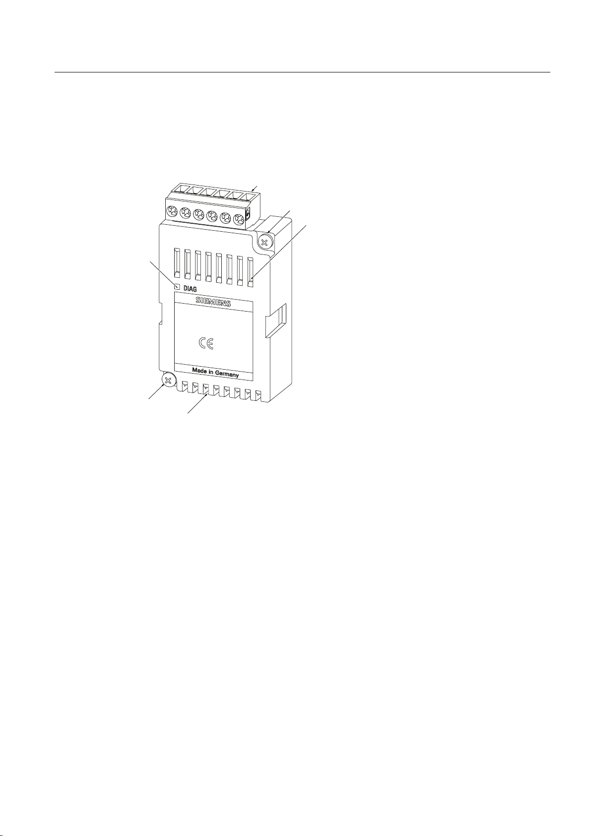
Figure 3-1 Schematic view of the side and front of the PAC RS485 expansion module
(1) Terminal block
(2) Screw for mounting the PAC RS485 expansion module on the SENTRON PAC
Power Monitoring Device
(3) Ventilation slots
(4) LED
PAC RS485
Manual, 02/2008, A5E02091800B-01
15
Description
3.5 Firmware
ཱ
ི
ཱི
ི
ཱ
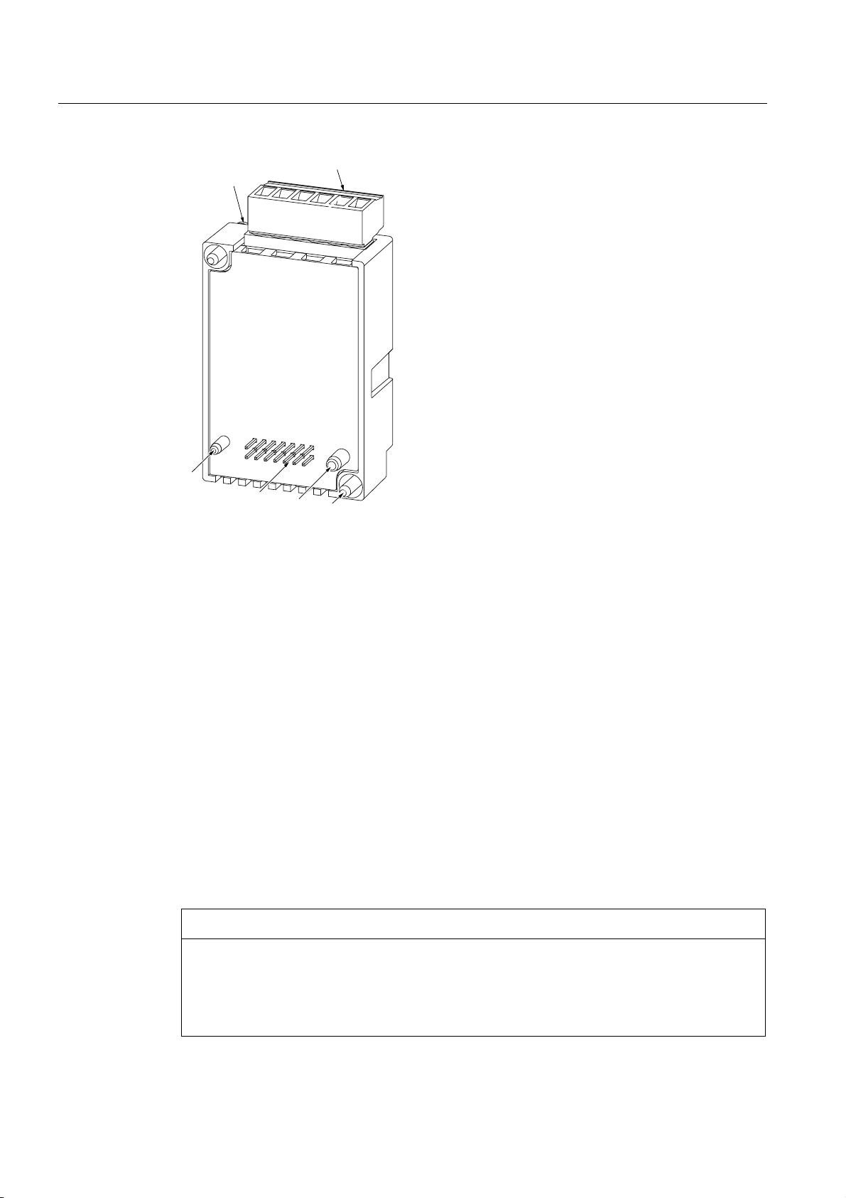
Figure 3-2 Schematic view of the rear of the PAC RS485 expansion module
(1) Terminal block
(2) Screw for mounting the PAC RS485 expansion module on the SENTRON PAC Power
(3) Guide pins; their guide for correct position ensures that the PAC RS485 expansion module is
(4) Pins
3.5 Firmware
General information
The PAC RS485 expansion module does not have its own firmware. The protocol of the
PAC RS485 expansion module is integrated into the firmware of the SENTRON PAC Power
Monitoring Device. New functions and changes to functions only become available after the
firmware of the SENTRON PAC Power Monitoring Device has been udpated.
NOTICE
The PAC RS485 expansion module will not work with the wrong firmware version
The SENTRON PAC3200 Power Monitoring Device must have at least firmware version
FWV2.0X. Earlier versions do not support the PAC RS485 expansion module. If necessary,
install the correct firmware version from V.1.0.1.0 with the program
SENTRON powerconfig
Monitoring Device
plugged into the SENTRON PAC Power Monitoring Device correctly
.
PAC RS485
16 Manual, 02/2008, A5E02091800B-01

Description
3.6 Bus and master
3.6 Bus and master
Restrictions
The following restrictions apply for the use of a bus and a master:
● You must use only broadcast commands that agree in syntax and meaning with the
broadcast commands supported by the Power Monitoring Device.
● The following must be set on the bus and the master and on all nodes on the bus:
– The same baud rate
– The same communication settings, e.g. data bits, stop bits, parity bit
– The same protocol
PAC RS485
Manual, 02/2008, A5E02091800B-01
17

Description
3.6 Bus and master
PAC RS485
18 Manual, 02/2008, A5E02091800B-01

Assembling
4.1 Procedure for installation and commissioning
The following system configuration information must be available:
● Installation location of the device
● Baud rate
● Planned address of the PAC RS485 expansion module
Procedure
1. Mount the SENTRON PAC Power Monitoring Device and the PAC RS485 expansion
module.
2. Connect the SENTRON PAC Power Monitoring Device.
3. Connect the PAC RS485 expansion module to the RS 485 network.
4. Switch on the terminating resistor at the start and the end of the bus.
5. Apply supply voltage to the SENTRON PAC Power Monitoring Device. The
SENTRON PAC Power Monitoring Device and expansion module are then ready for
operation.
4
6. Set the language on the SENTRON PAC Power Monitoring Device.
7. Parameterize the SENTRON PAC Power Monitoring Device.
8. Set the following on the SENTRON PAC Power Monitoring Device.
– The planned RS 485 address, e.g. the MODBUS address
– The baud rate
– The communication settings
– The protocol, e.g. MODBUS RTU or SEAbus
– The response time
9. Make the necessary settings on the master.
10. Check all connections and settings.
PAC RS485
Manual, 02/2008, A5E02091800B-01
19

Assembling
4.2 Unpacking
See also
Safety notes (Page 11)
Changing the address (Page 57)
Examples of MODBUS communication (Page 75)
Configuration of the PAC RS485 expansion module on the SENTRON PAC3200
Power Monitoring Device (Page 58)
4.2 Unpacking
Observe the ESD Guidelines. Open the packaging with care. Do not use excessive force.
Checks
After receiving the module, and before installing it, you should make the following checks:
Storage
See also
● Check the packaging for damage.
● Make sure that the package contents are complete.
● Check the module for external damage.
Please contact your Siemens sales partner in the following cases:
● The packaging is damaged
● The contents of the package are not complete
● The module is damaged
Store the PAC RS485 expansion module in a dry place.
Electrostatic sensitive devices (ESD) (Page 81)
PAC RS485
20 Manual, 02/2008, A5E02091800B-01

Assembling
4.3 Assembly
4.3 Assembly
Tools
Assembly
NOTICE
Condensation
Sudden fluctuations in temperature can lead to condensation. Condensation can affect the
function of the PAC RS485 expansion module. Store the PAC RS485 expansion module in
the operating room for at least 2 hours before commencing installation.
To install the PAC RS485 expansion module you will need the following tool:
● A cross-tip screwdriver PZ1, 0.5 Nm
cal. ISO 6789
Mount the PAC RS485 expansion module before starting up the SENTRON PAC. Observe
the ESD Guidelines.
CAUTION
Defective connector to SENTRON PAC Power Monitoring Device
Dirty or bent pins can affect the function of the connectors. The connectors can be
destroyed. Do not allow the pins to become dirty.
Make sure that:
• There are no metal parts between the pins.
• There are no metal parts adhering to the pins.
• The pins do not bend.
Do not touch the pins.
NOTICE
Do not cover the ventilation slots!
If the ventilation slots are covered, the PAC RS485 expansion module can overheat. Make
sure that the ventilation slots are not covered.
PAC RS485
Manual, 02/2008, A5E02091800B-01
21
Assembling
4.3 Assembly
[+/0[
[
61%[
1P
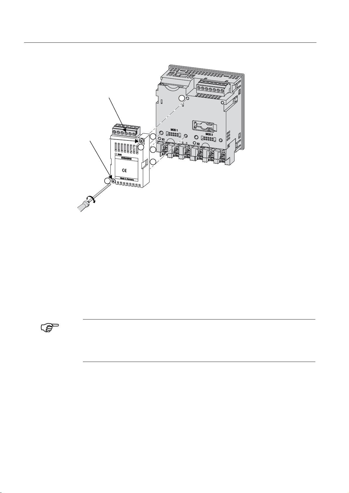
Figure 4-1 Schematic view of assembling the PAC RS485 expansion module
1. Ensure safe isolation from supply.
2. Discharge yourself.
3. Mount the SENTRON PAC Power Monitoring Device.
4. Connect the current terminals and voltage terminals to the SENTRON PAC.
5. Handle the PAC RS485 expansion module by the plastic housing only.
6. Connect the PAC RS485 expansion module to the SENTRON PAC. The guide for correct
position of the guide pins will help you to plug in the PAC RS485 expansion module
correctly. You can find more information about the slot in the SENTRON PAC manual.
7. Tighten the screws SN62217-B3x22 of the PAC RS485 expansion module to the
SENTRON PAC with a torque of 0.5 Nm.
More information
Installing the SENTRON PAC Power Monitoring Device
You can find information about how to install the SENTRON PAC Power Monitoring
Device in the operating instructions and manual for the SENTRON PAC Power
Monitoring Device.
PAC RS485
22 Manual, 02/2008, A5E02091800B-01

Assembling
4.4 Connecting
NOTICE
Damage due to moisture
Moisture or wetness can affect the operating capability of the PAC RS485 expansion
module. Make sure that no moisture or wetness can find its way into the PAC RS485
expansion module. Clean the PAC RS485 expansion module using a dry, lint-free cloth
only.
Do not operate the PAC RS485 expansion module in an environment affected by high
humidity or wetness. Note the environmental requirements of the SENTRON PAC
Power Monitoring Device.
See also
Electrostatic sensitive devices (ESD) (Page 81)
Connecting (Page 23)
Measures to be performed prior to start-up (Page 26)
4.4 Connecting
Tools required
To install the cables and the screw terminals, you will require:
● A cross-tip screwdriver PZ1, 0.5 Nm
cal. ISO 6789
If you use cables with wire end ferrules, you also require:
● A crimping tool in accordance with EN 60947-1
Procedure
Connect the PAC RS485 expansion module to the RS 485 bus. Please pay attention to the
general topology of the twisted-pair cable.
PAC RS485
Manual, 02/2008, A5E02091800B-01
23
Assembling
4.4 Connecting
0DVWHU
9
SXOOXS
38
7(57(5
SXOOGRZQ
3'
%DODQFHG3DLU
5
'
6ODYH 6ODYHQ
5
'
'
5
%
$
&RPPRQ
*URXQG
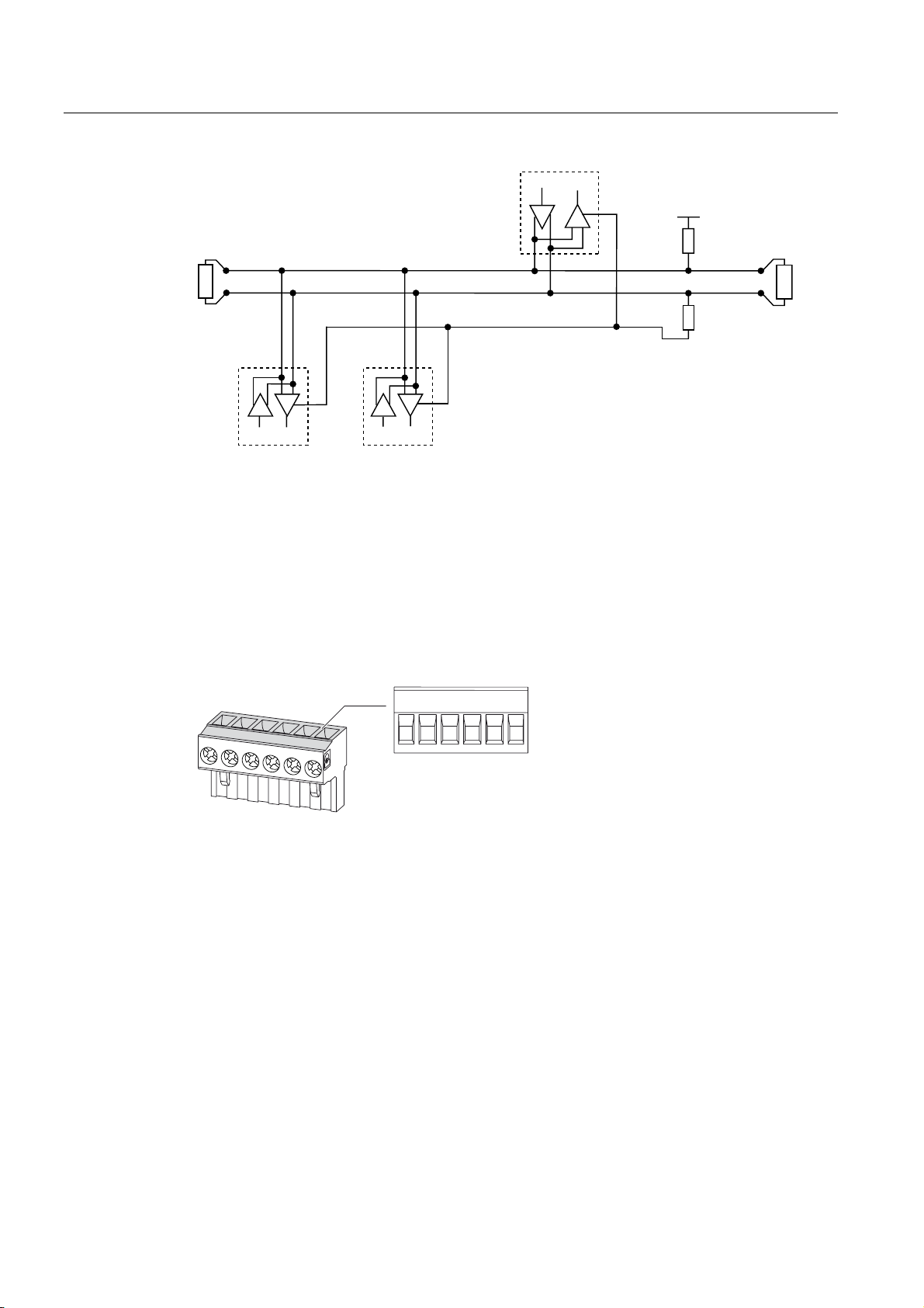
Figure 4-2 Block diagram: General topology of the twisted-pair cable
+/B B signal; D1
-/A A signal; D0
COM Common = Ground
TER (Line) Termination = bus terminating resistor
PU Pull-up resistor
PD Pull-down resistor
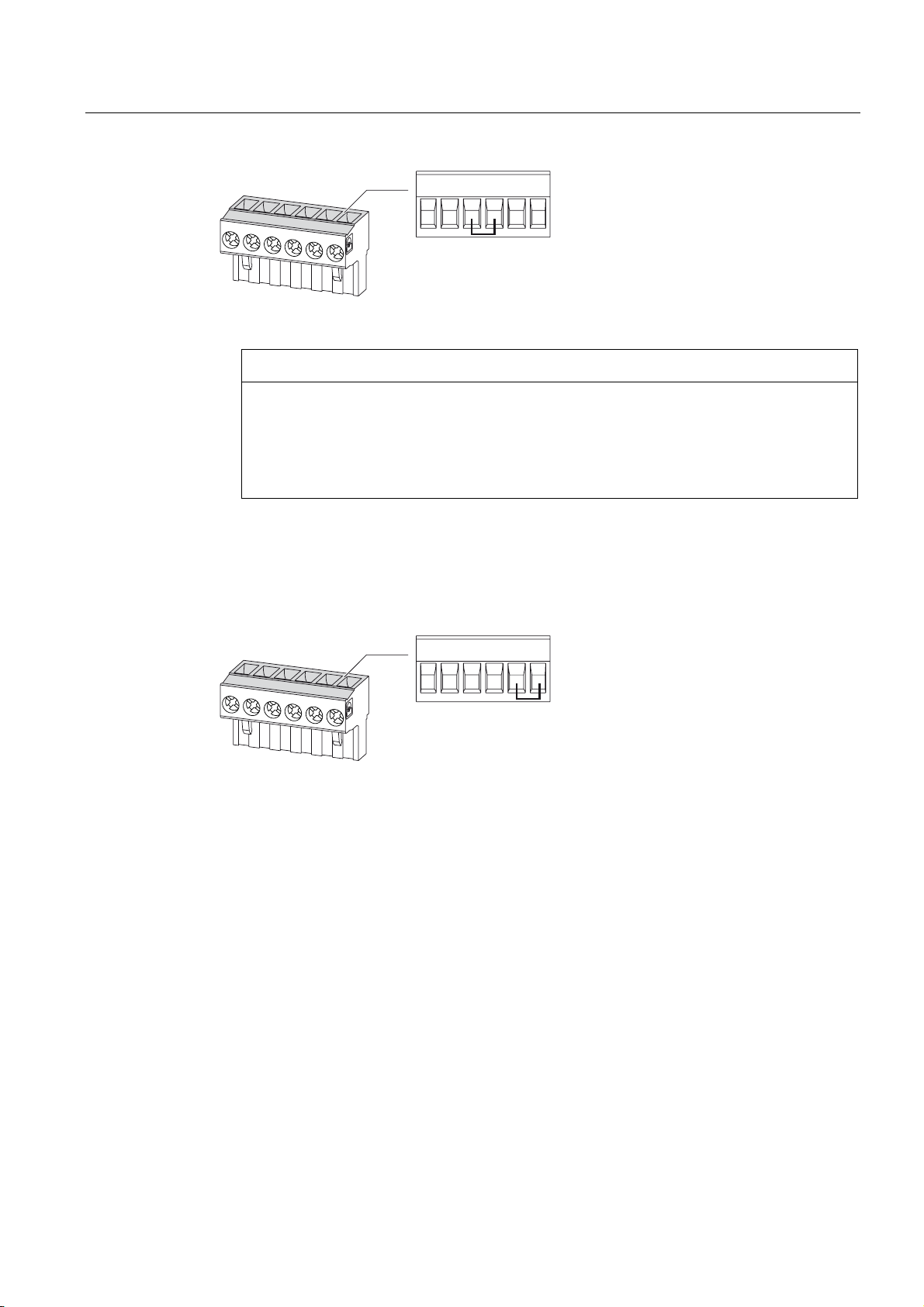
&RP % $ 7HU 38 3'
Figure 4-3 Terminal assignment
1. Connect the cables to the appropriate screw terminals on the terminal block. You can find
the assignments of the terminals in the figure "Terminal assignment".
2. Connect the cable shield at one end with protective ground PE.
3. Connect the signal Common with protective ground. This grounds the expansion module.
4. On the first and last communication nodes, switch a bus terminating resistor between the
positive signal and the negative signal. A 120-Ohm bus terminating resistor is
implemented in the PAC RS485 expansion module for this purpose. In the case of other
values, use an external bus terminating resistor. Attach this to the first and last
communication node.
PAC RS485
24 Manual, 02/2008, A5E02091800B-01
Assembling
4.4 Connecting
&RP % $ 7HU 38 3'
Figure 4-4 Terminal assignment with terminating resistor
NOTICE
Incorrect bus terminator
If you switch more than two bus terminating resistors on one bus, this can result, for
example, in signal reflections that interfere with communication on the bus.
Never attach more than two bus terminators to one bus. Attach one bus terminating
resistor at the start of the bus and one terminating resistor at the end of the bus.
5. Make sure that there is sufficient strain relief for the connected cables.
Line polarization
See also
A resistor for line polarization is implemented in the terminal block.
&RP % $ 7HU 38 3'
Figure 4-5 Terminal assignment with line polarization
If one or more communication nodes require line polarization, switch a resistor pair PU and
PD on the RS 485 twisted-pair cable in the case of a PAC RS485 expansion module. To do
so, switch on the resistor in the terminal block of the relevant PAC RS485 expansion module
shown in the figure "Terminal assignment with line polarization".
Assembly (Page 21)
Communication interface (Page 70)
PAC RS485
Manual, 02/2008, A5E02091800B-01
25

Assembling
4.5 Measures to be performed prior to start-up
4.5 Measures to be performed prior to start-up
Checks
CAUTION
Never start up damaged modules
Damaged components can impair and endanger operation. Never use damaged
components.
NOTICE
Condensation
Store the device in the service room for at least two hours before applying voltage to the
device for the first time. This will equalize the temperature and prevent the formation of
condensation.
Once you have correctly installed the PAC RS485 expansion module, you should carry out
the following checks:
1. Check that the PAC RS485 expansion module is connected to the SENTRON PAC
Power Monitoring Device correctly.
2. Check that the cables are correctly connected and screwed to the terminal block.
3. Check that the RS 485 bus is correctly grounded and shielded.
See also
4. Check that the ventilation slots are not covered.
5. Check that the relevant terminating resistors have been switched.
Assembly (Page 21)
Connecting (Page 23)
PAC RS485
26 Manual, 02/2008, A5E02091800B-01

Assembling
4.6 Disassembly
4.6 Disassembly
Disassembling
1. Ensure safe isolation from supply.
2. Observe the ESD Guidelines. Discharge yourself. Handle the PAC RS485 expansion
module by the plastic housing only.
3. Remove the terminal block from the expansion module, or detach the cable from the
terminal block.
4. Unscrew the PAC RS485 expansion module from the SENTRON PAC Power Monitoring
Device.
5. Remove the PAC RS485 expansion module from the SENTRON PAC Power Monitoring
Device.
See also
6. If necessary, disassemble the SENTRON PAC Power Monitoring Device.
More information
Disassembling the SENTRON PAC Power Monitoring Device
You can find information about how to disassemble the SENTRON PAC Power
Monitoring Device in the manual for the SENTRON PAC Power Monitoring Device.
Electrostatic sensitive devices (ESD) (Page 81)
PAC RS485
Manual, 02/2008, A5E02091800B-01
27

Assembling
4.6 Disassembly
PAC RS485
28 Manual, 02/2008, A5E02091800B-01
 Loading...