

Siemens SENTRON PAC5200,SENTRON PAC5100 Device Manual

Preface
Open Source Software
Contents
Power Monitoring Device
and
Power Quality Recorder
SENTRON PAC5100/5200
7KM5212/5412
V1.00
Device Manual
User Information 1
Overview 2
Device Design 3
Measurands and Recording 4
Getting Started 5
Connection Principle 6
Operation at Use of a PC 7
Operation at Use of the Display 8
Time Synchronization 9
Maintenance, Storage, Transport 10
E50417-H1040-C568-A1
Failures and LED Indications 11
Technical Data 12
Operational Indications 13
Operating Parameters 14
Glossary
Index

NOTE
For your own safety, please observe the warnings and safety instructions contained in this document.
Disclaimer of Liability
This document has been subjected to rigorous technical review
before being published. It is revised at regular intervals, and any
modifications and amendments are included in the subsequent
issues. The content of this document has been compiled for
information purposes only. Although Siemens AG has made best
efforts to keep the document as precise and up-to-date as possible,
Siemens AG shall not assume any liability for defects and damage
which result through use of the information contained herein.
This content does not form part of a contract or of business
relations; nor does it change these. All obligations of Siemens AG
are stated in the relevant contractual agreements.
Siemens AG reserves the right to revise this document from time to
time.
Document version: E50417-H1040-C568-A1.00
Edition 03.2015
Version of the product described: V1.00
Copyright
Copyright Siemens AG 2015. All rights reserved.
The disclosure, duplication, distribution and editing of this
document, or utilization and communication of the content are not
permitted, unless authorized in writing. All rights, including rights
created by patent grant or registration of a utility model or a design,
are reserved.
Registered Trademarks
SENTRON
unauthorized use is illegal.
All other designations in this document can be trademarks whose
use by third parties for their own purposes can infringe the rights of
the owner.
®
is a registered trademark of SIEMENS AG. An

Preface
Purpose of this Manual
This manual describes the application, functions, installation, commissioning, and operation of the
Power Monitoring Device and Power Quality Recorder SENTRON PAC5100/5200 7KM5212/5412.
Targe t G r o u p
This manual is intended for project engineers, commissioning and operating personnel in electrical systems
and power plants.
Scope of Validity of this Manual
This manual is valid for the Power Monitoring Device and Power Quality Recorder SENTRON PAC5100/5200
7KM5212/5412.
Further Support
For any questions concerning your system, please contact your Siemens representative.
Siemens provides around-the-clock support.
Phone: +49 (911) 895-7222
Fax: +49 (911) 895-7223
Internet: http://www.siemens.com/automation/service&support
Training Courses
If you are interested in our current training program, please contact our training center:
Siemens AG
Siemens Power Academy TD
Humboldtstr. 59
D-90459 Nuremberg
Tel.: +49 (911) 433-7415
Fax: +49 (911) 433-7929
Internet: http://www.siemens.com/poweracademy
e-mail: poweracademy@siemens.com
E50417-H1040-C568-A1, Edition 03.2015
3SENTRON PAC5100/5200, 7KM5212/5412, Device Manual
Notes On Safety
This manual is not a complete index of all safety measures required for operation of the equipment (module,
device). However, it comprises important information that must be noted for purposes of personal safety, as
well as in order to avoid material damage. Information is highlighted and illustrated as follows according to the
degree of danger.
DANGER
DANGER means that death or severe injury will occur if the appropriate safety measures are not taken.
✧ Follow all advice instructions to prevent death or severe injury.
WARNING
WARNING means that death or severe injury can occur if the appropriate safety measures are not taken.
✧ Follow all advice instructions to prevent death or severe injury.
CAUTION
CAUTION means that minor or moderate injury can occur if the appropriate safety measures are not taken.
✧ Follow all advice instructions to prevent minor injury.
NOTICE
NOTICE means that damage to property can occur if the appropriate safety measures are not taken.
✧ Follow all advice instructions to prevent damage to property.
NOTE
is important information about the product, the handling of the product, or the part of the documentation in
question to which special attention must be paid.
4 SENTRON PAC5100/5200, 7KM5212/5412, Device Manual
E50417-H1040-C568-A1, Edition 03.2015

Personnel Qualified in Electrical Engineering
Only qualified electrical engineering personnel may commission and operate the equipment (module, device)
described in this document. Qualified electrical engineering personnel in the sense of this manual are people
who can demonstrate technical qualifications as electrical technicians. These persons may commission, isolate, ground, and label devices, systems and circuits according to the standards of safety engineering.
Use as Prescribed
The equipment (device, module) must not be used for any other purposes than those described in the Catalog
and the Technical Description. If it is used together with third-party devices and components, these must be
recommended or approved by Siemens.
If the device is not used in accordance with the operating instruction and this manual, the scheduled protection
is impaired.
Problem-free and safe operation of the product depends on the following:
• Proper transport
• Proper storage, setup, and installation
• Proper operation and maintenance
When electrical equipment is operated, hazardous voltages are inevitably present in certain parts. If proper action is not taken, death, severe injury, or property damage can result.
• The equipment must be grounded at the grounding terminal before any connections are made.
• All circuit components connected to the power supply may be subject to dangerous voltage.
• Hazardous voltages may be present in equipment even after the supply voltage has been disconnected
(capacitors can still be charged).
• Equipment with exposed current transformer circuits must not be operated. Prior to disconnecting the
equipment, ensure that the current transformer circuits are short-circuited.
• The limit values stated in the document may not be exceeded. This must also be considered during testing
and commissioning.
E50417-H1040-C568-A1, Edition 03.2015
5SENTRON PAC5100/5200, 7KM5212/5412, Device Manual
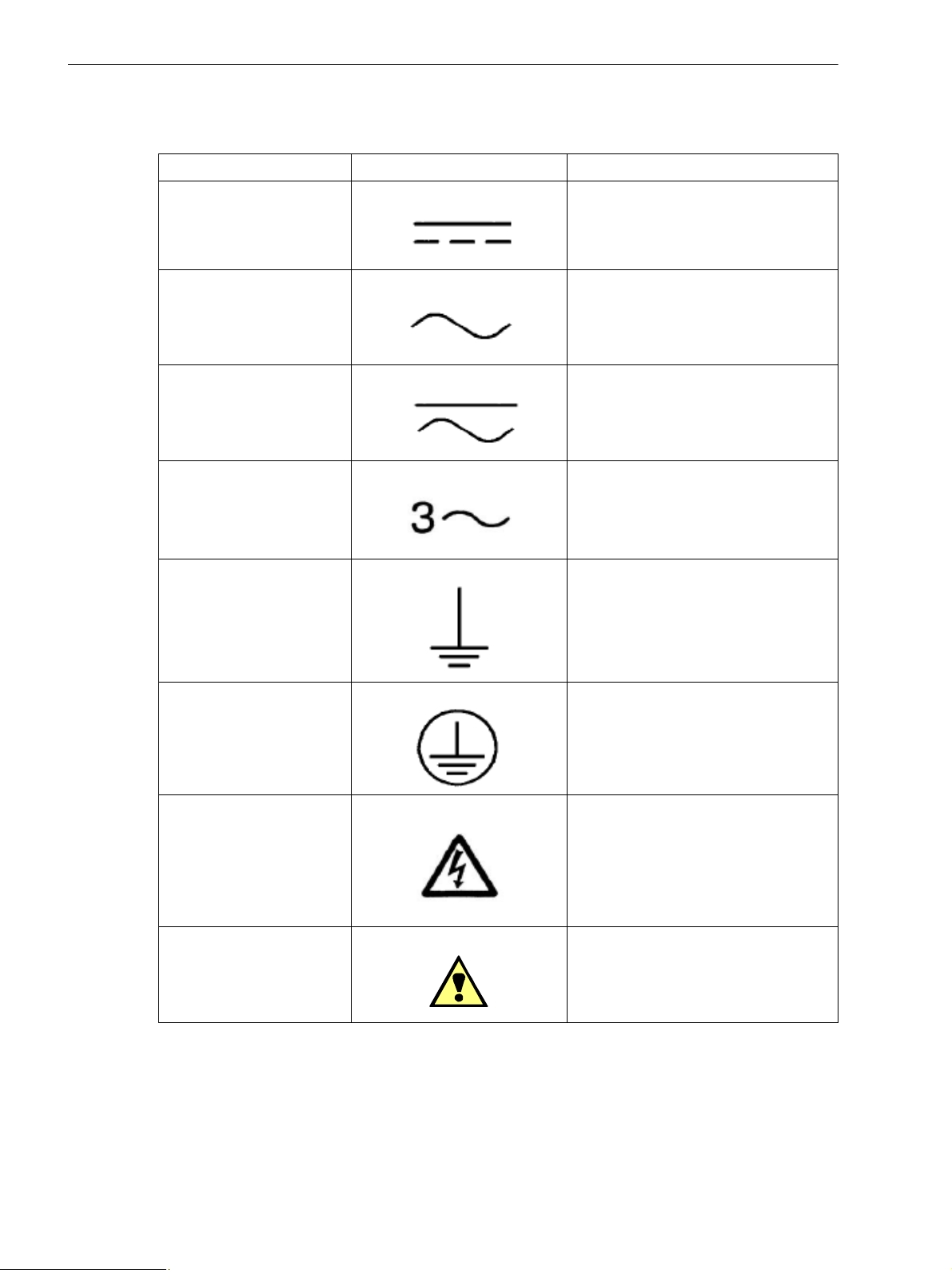
Used Symbols
No. Symbol Description
1 Direct current
IEC 60417-5031
2 Alternating current
IEC 60417-5032
3 Direct and alternating current
IEC 60417-5033
4 Three-phase alternating current
5 Earth (ground) terminal
IEC 60417-5017
6 Protective conductor terminal
IEC 60417-5019
7 Caution, risk of electric shock
8 Caution, risk of danger
ISO 7000-0434
6 SENTRON PAC5100/5200, 7KM5212/5412, Device Manual
E50417-H1040-C568-A1, Edition 03.2015
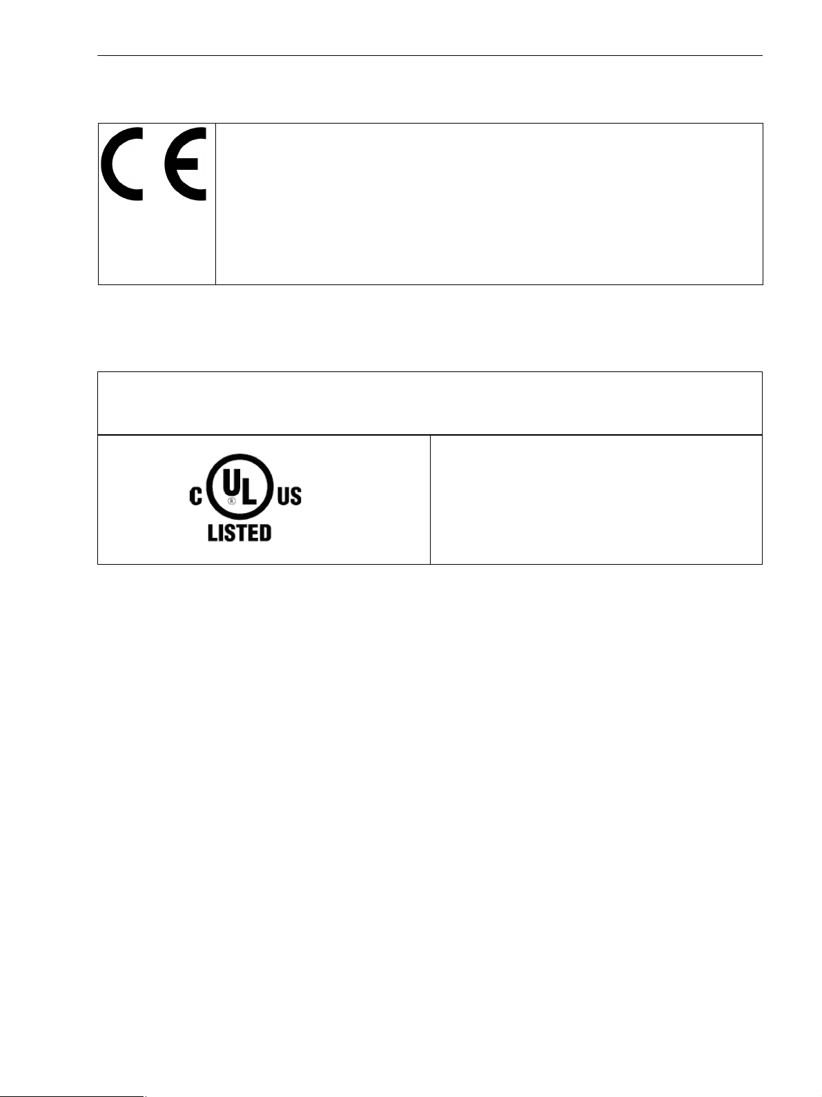
Statement of Conformity
This product complies with the directive of the Council of the European Communities on the
approximation of the laws of the Member States relating to electromagnetic compatibility (EMC
Council Directive 2004/108/EC) and concerning electrical equipment for use within specified voltage
limits (Low-voltage Directive 2006/95/EC).
This conformity has been established by means of tests conducted by Siemens AG according to the
Council Directive in agreement with the generic standards EN 61000-6-2 and EN 61000-6-4 for the
EMC directives, and with the standard EN 61010-1 for the low-voltage directive.
The device has been designed and produced for industrial use.
The product conforms to the standard IEC 61557-12.
Further Standards
This product is UL-certified to Standard UL 61010-1, third edition, based on the specification stated in Chapter 12
(Technical Data).
UL File No.: E228586
Open-type Measuring Equipment
2UD1
For further information see UL database on the internet: http://ul.com.
Chose Online Certifications Directory and insert E228586 under UL File Number.
E50417-H1040-C568-A1, Edition 03.2015
7SENTRON PAC5100/5200, 7KM5212/5412, Device Manual

8 SENTRON PAC5100/5200, 7KM5212/5412, Device Manual
E50417-H1040-C568-A1, Edition 03.2015

Open Source Software
The product contains, among other things, Open Source Software developed by third parties. The Open
Source Software used in the product and the license agreements concerning this software can be found in the
Readme_OSS.
These Open Source Software files are protected by copyright. Your compliance with those license conditions
will entitle you to use the Open Source Software as foreseen in the relevant license. In the event of conflicts
between Siemens license conditions and the Open Source Software license conditions, the Open Source Software conditions shall prevail with respect to the Open Source Software portions of the software.
The Open Source Software is licensed royalty-free. Insofar as the applicable Open Source Software License
Conditions provide for it you can order the source code of the Open Source Software from your Siemens sales
contact - against payment of the shipping and handling charges - for a period of at least 3 years since purchase
of the Product. We are liable for the Product including the Open Source Software contained in it pursuant to
the license conditions applicable to the Product. Any liability for the Open Source Software beyond the program
flow intended for the Product is explicitly excluded. Furthermore any liability for defects resulting from modifications to the Open Source Software by you or third parties is excluded. We do not provide any technical support for the Product if it has been modified.
E50417-H1040-C568-A1, Edition 03.2015
9SENTRON PAC5100/5200, 7KM5212/5412, Device Manual

10 SENTRON PAC5100/5200, 7KM5212/5412, Device Manual
E50417-H1040-C568-A1, Edition 03.2015

Contents
Preface . . . . . . . . . . . . . . . . . . . . . . . . . . . . . . . . . . . . . . . . . . . . . . . . . . . . . . . . . . . . . . . . . . . . . . . . . . . . . . . . . . 3
Open Source Software . . . . . . . . . . . . . . . . . . . . . . . . . . . . . . . . . . . . . . . . . . . . . . . . . . . . . . . . . . . . . . . . . . . . . 9
1 User Information . . . . . . . . . . . . . . . . . . . . . . . . . . . . . . . . . . . . . . . . . . . . . . . . . . . . . . . . . . . . . . . . . . . . . . . . . 15
2 Overview. . . . . . . . . . . . . . . . . . . . . . . . . . . . . . . . . . . . . . . . . . . . . . . . . . . . . . . . . . . . . . . . . . . . . . . . . . . . . . . . 17
2.1 Device Versions . . . . . . . . . . . . . . . . . . . . . . . . . . . . . . . . . . . . . . . . . . . . . . . . . . . . . . . . . . . . . . . . . . 18
2.2 Ordering Information and Scope of Delivery. . . . . . . . . . . . . . . . . . . . . . . . . . . . . . . . . . . . . . . . . . . . . 19
3 Device Design . . . . . . . . . . . . . . . . . . . . . . . . . . . . . . . . . . . . . . . . . . . . . . . . . . . . . . . . . . . . . . . . . . . . . . . . . . . 21
3.1 Mechanical Design . . . . . . . . . . . . . . . . . . . . . . . . . . . . . . . . . . . . . . . . . . . . . . . . . . . . . . . . . . . . . . . . 22
3.2 Display and Softkeys . . . . . . . . . . . . . . . . . . . . . . . . . . . . . . . . . . . . . . . . . . . . . . . . . . . . . . . . . . . . . . 23
3.3 Electrical Design . . . . . . . . . . . . . . . . . . . . . . . . . . . . . . . . . . . . . . . . . . . . . . . . . . . . . . . . . . . . . . . . . . 24
4 Measurands and Recording . . . . . . . . . . . . . . . . . . . . . . . . . . . . . . . . . . . . . . . . . . . . . . . . . . . . . . . . . . . . . . . . 25
4.1 Measuring and Recording System . . . . . . . . . . . . . . . . . . . . . . . . . . . . . . . . . . . . . . . . . . . . . . . . . . . . 26
4.1.1 Functioning of the Measuring System according to IEC 61000-4-30 . . . . . . . . . . . . . . . . . . . . . . . 26
4.1.2 Recording of Measurands and Events in SENTRON PAC5200 . . . . . . . . . . . . . . . . . . . . . . . . . . . 31
4.2 Measurands . . . . . . . . . . . . . . . . . . . . . . . . . . . . . . . . . . . . . . . . . . . . . . . . . . . . . . . . . . . . . . . . . . . . . 39
4.2.1 Measurands in 1-phase Systems . . . . . . . . . . . . . . . . . . . . . . . . . . . . . . . . . . . . . . . . . . . . . . . . . . 39
4.2.2 Measurands in 3-wire and 4-wire Networks . . . . . . . . . . . . . . . . . . . . . . . . . . . . . . . . . . . . . . . . . . 40
4.2.3 Measurands Depending on the Connection Type. . . . . . . . . . . . . . . . . . . . . . . . . . . . . . . . . . . . . . 41
4.2.4 Data Availability for SENTRON PAC5100 . . . . . . . . . . . . . . . . . . . . . . . . . . . . . . . . . . . . . . . . . . . 48
4.2.5 Data Availability for SENTRON PAC5200 . . . . . . . . . . . . . . . . . . . . . . . . . . . . . . . . . . . . . . . . . . . 54
4.3 Display of Measurands. . . . . . . . . . . . . . . . . . . . . . . . . . . . . . . . . . . . . . . . . . . . . . . . . . . . . . . . . . . . . 64
4.3.1 Measurands and Operational Measurement Uncertainty acc. to IEC 62586-1 Product Standard,
Class S, and Standards IEC 61000-4-30, Ed. 2 and IEC 61000-4-7 and IEC 61000-4-15. . . . . . . 64
4.3.2 Measurands and Operational Measurement Accuracy acc. to IEC 61557-12 . . . . . . . . . . . . . . . . 65
4.3.3 Accuracy of the Frequency Measurement . . . . . . . . . . . . . . . . . . . . . . . . . . . . . . . . . . . . . . . . . . . 66
5 Getting Started. . . . . . . . . . . . . . . . . . . . . . . . . . . . . . . . . . . . . . . . . . . . . . . . . . . . . . . . . . . . . . . . . . . . . . . . . . . 67
5.1 Unpacking, Inspecting the Delivery, and Installing the Battery. . . . . . . . . . . . . . . . . . . . . . . . . . . . . . . 68
5.2 Assembly . . . . . . . . . . . . . . . . . . . . . . . . . . . . . . . . . . . . . . . . . . . . . . . . . . . . . . . . . . . . . . . . . . . . . . . 71
5.2.1 General Assembly Notes . . . . . . . . . . . . . . . . . . . . . . . . . . . . . . . . . . . . . . . . . . . . . . . . . . . . . . . . 71
5.2.2 Assembly. . . . . . . . . . . . . . . . . . . . . . . . . . . . . . . . . . . . . . . . . . . . . . . . . . . . . . . . . . . . . . . . . . . . . 72
5.3 Electrical Connection . . . . . . . . . . . . . . . . . . . . . . . . . . . . . . . . . . . . . . . . . . . . . . . . . . . . . . . . . . . . . . 74
5.3.1 Safety Notes . . . . . . . . . . . . . . . . . . . . . . . . . . . . . . . . . . . . . . . . . . . . . . . . . . . . . . . . . . . . . . . . . . 74
5.3.2 Electrical Connection of SENTRON PAC5100/5200 . . . . . . . . . . . . . . . . . . . . . . . . . . . . . . . . . . . 75
5.4 System Requirements . . . . . . . . . . . . . . . . . . . . . . . . . . . . . . . . . . . . . . . . . . . . . . . . . . . . . . . . . . . . . 76
5.5 Access Rights . . . . . . . . . . . . . . . . . . . . . . . . . . . . . . . . . . . . . . . . . . . . . . . . . . . . . . . . . . . . . . . . . . . . 77
E50417-H1040-C568-A1, Edition 03.2015
11SENTRON PAC5100/5200, 7KM5212/5412, Device Manual

5.6 Meaning of the LEDs . . . . . . . . . . . . . . . . . . . . . . . . . . . . . . . . . . . . . . . . . . . . . . . . . . . . . . . . . . . . . . 78
5.7 Commissioning. . . . . . . . . . . . . . . . . . . . . . . . . . . . . . . . . . . . . . . . . . . . . . . . . . . . . . . . . . . . . . . . . . . 79
5.7.1 Initial Commissioning . . . . . . . . . . . . . . . . . . . . . . . . . . . . . . . . . . . . . . . . . . . . . . . . . . . . . . . . . . 79
5.7.2 Changes During Operation. . . . . . . . . . . . . . . . . . . . . . . . . . . . . . . . . . . . . . . . . . . . . . . . . . . . . . . 80
5.7.3 Starting the Device with the Default IP Address. . . . . . . . . . . . . . . . . . . . . . . . . . . . . . . . . . . . . . . 81
6 Connection Principle . . . . . . . . . . . . . . . . . . . . . . . . . . . . . . . . . . . . . . . . . . . . . . . . . . . . . . . . . . . . . . . . . . . . . 83
6.1 Terminals . . . . . . . . . . . . . . . . . . . . . . . . . . . . . . . . . . . . . . . . . . . . . . . . . . . . . . . . . . . . . . . . . . . . . . . 84
6.2 Ethernet Interface. . . . . . . . . . . . . . . . . . . . . . . . . . . . . . . . . . . . . . . . . . . . . . . . . . . . . . . . . . . . . . . . . 86
6.3 Connection Types and Connection Examples . . . . . . . . . . . . . . . . . . . . . . . . . . . . . . . . . . . . . . . . . . . 87
6.3.1 Using SENTRON PAC5100/5200 in the Power Systems IT, TT, and TN . . . . . . . . . . . . . . . . . . . 87
6.3.2 Connection Types . . . . . . . . . . . . . . . . . . . . . . . . . . . . . . . . . . . . . . . . . . . . . . . . . . . . . . . . . . . . . 87
6.3.3 Examples - Standard Application . . . . . . . . . . . . . . . . . . . . . . . . . . . . . . . . . . . . . . . . . . . . . . . . . . 87
6.3.4 Example - Special Application . . . . . . . . . . . . . . . . . . . . . . . . . . . . . . . . . . . . . . . . . . . . . . . . . . . . 94
7 Operation at Use of a PC . . . . . . . . . . . . . . . . . . . . . . . . . . . . . . . . . . . . . . . . . . . . . . . . . . . . . . . . . . . . . . . . . . 95
7.1 General Usage Notes. . . . . . . . . . . . . . . . . . . . . . . . . . . . . . . . . . . . . . . . . . . . . . . . . . . . . . . . . . . . . . 96
7.2 Start and Design of the User Interface. . . . . . . . . . . . . . . . . . . . . . . . . . . . . . . . . . . . . . . . . . . . . . . . . 97
7.2.1 Initial Start of the Operation . . . . . . . . . . . . . . . . . . . . . . . . . . . . . . . . . . . . . . . . . . . . . . . . . . . . . . 97
7.2.2 Enabling JavaScript . . . . . . . . . . . . . . . . . . . . . . . . . . . . . . . . . . . . . . . . . . . . . . . . . . . . . . . . . . . . 98
7.2.3 Number of Connections via HTML . . . . . . . . . . . . . . . . . . . . . . . . . . . . . . . . . . . . . . . . . . . . . . . . . 99
7.2.4 Layout of the User Interface . . . . . . . . . . . . . . . . . . . . . . . . . . . . . . . . . . . . . . . . . . . . . . . . . . . . . 100
7.2.5 Starting the User Interface during Operation . . . . . . . . . . . . . . . . . . . . . . . . . . . . . . . . . . . . . . . . 101
7.3 Configuration of the Device . . . . . . . . . . . . . . . . . . . . . . . . . . . . . . . . . . . . . . . . . . . . . . . . . . . . . . . . 106
7.3.1 Device Configuration Procedure . . . . . . . . . . . . . . . . . . . . . . . . . . . . . . . . . . . . . . . . . . . . . . . . . 106
7.3.2 Access to the Passive Set of Parameters by Multiple Users . . . . . . . . . . . . . . . . . . . . . . . . . . . . 114
7.3.3 Setting the Operational Parameters . . . . . . . . . . . . . . . . . . . . . . . . . . . . . . . . . . . . . . . . . . . . . . . 115
7.3.4 HMI. . . . . . . . . . . . . . . . . . . . . . . . . . . . . . . . . . . . . . . . . . . . . . . . . . . . . . . . . . . . . . . . . . . . . . . . 130
7.3.5 Recording and Reporting . . . . . . . . . . . . . . . . . . . . . . . . . . . . . . . . . . . . . . . . . . . . . . . . . . . . . . . 134
7.3.6 Setting Administrative Parameters . . . . . . . . . . . . . . . . . . . . . . . . . . . . . . . . . . . . . . . . . . . . . . . . 149
7.4 Value View and Evaluation . . . . . . . . . . . . . . . . . . . . . . . . . . . . . . . . . . . . . . . . . . . . . . . . . . . . . . . . 157
7.4.1 Process Connections and Automation Functions. . . . . . . . . . . . . . . . . . . . . . . . . . . . . . . . . . . . . 157
7.4.2 Evaluation and Data Management . . . . . . . . . . . . . . . . . . . . . . . . . . . . . . . . . . . . . . . . . . . . . . . . 158
7.5 Maintenance. . . . . . . . . . . . . . . . . . . . . . . . . . . . . . . . . . . . . . . . . . . . . . . . . . . . . . . . . . . . . . . . . . . . 173
7.5.1 Firmware Upload . . . . . . . . . . . . . . . . . . . . . . . . . . . . . . . . . . . . . . . . . . . . . . . . . . . . . . . . . . . . . 174
7.5.2 Formatting the SD Card . . . . . . . . . . . . . . . . . . . . . . . . . . . . . . . . . . . . . . . . . . . . . . . . . . . . . . . . 176
7.5.3 Presets . . . . . . . . . . . . . . . . . . . . . . . . . . . . . . . . . . . . . . . . . . . . . . . . . . . . . . . . . . . . . . . . . . . . . 177
7.5.4 Message Logs . . . . . . . . . . . . . . . . . . . . . . . . . . . . . . . . . . . . . . . . . . . . . . . . . . . . . . . . . . . . . . . 181
7.5.5 Diagnosis Modbus TCP . . . . . . . . . . . . . . . . . . . . . . . . . . . . . . . . . . . . . . . . . . . . . . . . . . . . . . . . 183
7.6 Example of a Parameterization and Measured Value Evaluation for SENTRON PAC5200 . . . . . . . 184
7.6.1 Task Definition . . . . . . . . . . . . . . . . . . . . . . . . . . . . . . . . . . . . . . . . . . . . . . . . . . . . . . . . . . . . . . . 184
7.6.2 Initial Situation . . . . . . . . . . . . . . . . . . . . . . . . . . . . . . . . . . . . . . . . . . . . . . . . . . . . . . . . . . . . . . . 184
7.6.3 Parameterization as Defined by the Task . . . . . . . . . . . . . . . . . . . . . . . . . . . . . . . . . . . . . . . . . . 186
7.6.4 Performing the Measurement. . . . . . . . . . . . . . . . . . . . . . . . . . . . . . . . . . . . . . . . . . . . . . . . . . . . 190
12 SENTRON PAC5100/5200, 7KM5212/5412, Device Manual
E50417-H1040-C568-A1, Edition 03.2015

8 Operation at Use of the Display . . . . . . . . . . . . . . . . . . . . . . . . . . . . . . . . . . . . . . . . . . . . . . . . . . . . . . . . . . . . 191
8.1 General Operating Instructions. . . . . . . . . . . . . . . . . . . . . . . . . . . . . . . . . . . . . . . . . . . . . . . . . . . . . . 192
8.2 Starting Operation. . . . . . . . . . . . . . . . . . . . . . . . . . . . . . . . . . . . . . . . . . . . . . . . . . . . . . . . . . . . . . . . 194
8.3 Display Content . . . . . . . . . . . . . . . . . . . . . . . . . . . . . . . . . . . . . . . . . . . . . . . . . . . . . . . . . . . . . . . . . 195
8.4 Parameterization. . . . . . . . . . . . . . . . . . . . . . . . . . . . . . . . . . . . . . . . . . . . . . . . . . . . . . . . . . . . . . . . . 197
8.4.1 Menu Tree of the Main Menu . . . . . . . . . . . . . . . . . . . . . . . . . . . . . . . . . . . . . . . . . . . . . . . . . . . . 197
8.4.2 Measurands Submenus . . . . . . . . . . . . . . . . . . . . . . . . . . . . . . . . . . . . . . . . . . . . . . . . . . . . . . . . 198
8.4.3 Submenus for Diagnostics . . . . . . . . . . . . . . . . . . . . . . . . . . . . . . . . . . . . . . . . . . . . . . . . . . . . . . 200
8.4.4 Menu Tree of the Settings Submenu . . . . . . . . . . . . . . . . . . . . . . . . . . . . . . . . . . . . . . . . . . . . . . 201
8.4.5 User-defined Screens Submenus . . . . . . . . . . . . . . . . . . . . . . . . . . . . . . . . . . . . . . . . . . . . . . . . . 210
9 Time Synchronization . . . . . . . . . . . . . . . . . . . . . . . . . . . . . . . . . . . . . . . . . . . . . . . . . . . . . . . . . . . . . . . . . . . . 211
9.1 General. . . . . . . . . . . . . . . . . . . . . . . . . . . . . . . . . . . . . . . . . . . . . . . . . . . . . . . . . . . . . . . . . . . . . . . . 212
9.2 Internal Time Keeping. . . . . . . . . . . . . . . . . . . . . . . . . . . . . . . . . . . . . . . . . . . . . . . . . . . . . . . . . . . . . 212
9.2.1 Time Format . . . . . . . . . . . . . . . . . . . . . . . . . . . . . . . . . . . . . . . . . . . . . . . . . . . . . . . . . . . . . . . . . 212
9.2.2 Status Bits. . . . . . . . . . . . . . . . . . . . . . . . . . . . . . . . . . . . . . . . . . . . . . . . . . . . . . . . . . . . . . . . . . . 212
9.3 External Time Synchronization per NTP. . . . . . . . . . . . . . . . . . . . . . . . . . . . . . . . . . . . . . . . . . . . . . . 213
9.4 External Time Synchronization via Fieldbus. . . . . . . . . . . . . . . . . . . . . . . . . . . . . . . . . . . . . . . . . . . . 214
9.5 Internal Time Synchronization via RTC . . . . . . . . . . . . . . . . . . . . . . . . . . . . . . . . . . . . . . . . . . . . . . . 214
10 Maintenance, Storage, Transport. . . . . . . . . . . . . . . . . . . . . . . . . . . . . . . . . . . . . . . . . . . . . . . . . . . . . . . . . . . 215
10.1 Maintenance . . . . . . . . . . . . . . . . . . . . . . . . . . . . . . . . . . . . . . . . . . . . . . . . . . . . . . . . . . . . . . . . . . . . 216
10.2 Storage . . . . . . . . . . . . . . . . . . . . . . . . . . . . . . . . . . . . . . . . . . . . . . . . . . . . . . . . . . . . . . . . . . . . . . . . 216
10.3 Transport . . . . . . . . . . . . . . . . . . . . . . . . . . . . . . . . . . . . . . . . . . . . . . . . . . . . . . . . . . . . . . . . . . . . . . 216
11 Failures and LED Indications . . . . . . . . . . . . . . . . . . . . . . . . . . . . . . . . . . . . . . . . . . . . . . . . . . . . . . . . . . . . . . 217
11.1 General Inspection . . . . . . . . . . . . . . . . . . . . . . . . . . . . . . . . . . . . . . . . . . . . . . . . . . . . . . . . . . . . . . . 218
11.2 Commissioning during Failures . . . . . . . . . . . . . . . . . . . . . . . . . . . . . . . . . . . . . . . . . . . . . . . . . . . . . 219
11.2.1 Automatic Start of the Boot Loader. . . . . . . . . . . . . . . . . . . . . . . . . . . . . . . . . . . . . . . . . . . . . . . . 219
11.2.2 Manual Start of the Boot Loader . . . . . . . . . . . . . . . . . . . . . . . . . . . . . . . . . . . . . . . . . . . . . . . . . . 220
11.3 Indications Signaled by LEDs. . . . . . . . . . . . . . . . . . . . . . . . . . . . . . . . . . . . . . . . . . . . . . . . . . . . . . . 221
11.4 Troubleshooting and Repair . . . . . . . . . . . . . . . . . . . . . . . . . . . . . . . . . . . . . . . . . . . . . . . . . . . . . . . . 226
12 Technical Data . . . . . . . . . . . . . . . . . . . . . . . . . . . . . . . . . . . . . . . . . . . . . . . . . . . . . . . . . . . . . . . . . . . . . . . . . . 227
12.1 General Device Data . . . . . . . . . . . . . . . . . . . . . . . . . . . . . . . . . . . . . . . . . . . . . . . . . . . . . . . . . . . . . 228
12.1.1 Power Supply . . . . . . . . . . . . . . . . . . . . . . . . . . . . . . . . . . . . . . . . . . . . . . . . . . . . . . . . . . . . . . . . 228
12.1.2 Inputs and Outputs . . . . . . . . . . . . . . . . . . . . . . . . . . . . . . . . . . . . . . . . . . . . . . . . . . . . . . . . . . . . 229
12.1.3 Communication Interface . . . . . . . . . . . . . . . . . . . . . . . . . . . . . . . . . . . . . . . . . . . . . . . . . . . . . . . 231
12.1.4 Environmental Conditions . . . . . . . . . . . . . . . . . . . . . . . . . . . . . . . . . . . . . . . . . . . . . . . . . . . . . . . 231
12.1.5 General Data. . . . . . . . . . . . . . . . . . . . . . . . . . . . . . . . . . . . . . . . . . . . . . . . . . . . . . . . . . . . . . . . . 232
12.2 Test Data . . . . . . . . . . . . . . . . . . . . . . . . . . . . . . . . . . . . . . . . . . . . . . . . . . . . . . . . . . . . . . . . . . . . . . 232
12.2.1 Electrical Tests . . . . . . . . . . . . . . . . . . . . . . . . . . . . . . . . . . . . . . . . . . . . . . . . . . . . . . . . . . . . . . . 233
12.2.2 Mechanical Stress Tests. . . . . . . . . . . . . . . . . . . . . . . . . . . . . . . . . . . . . . . . . . . . . . . . . . . . . . . . 234
12.2.3 Climatic Stress Tests . . . . . . . . . . . . . . . . . . . . . . . . . . . . . . . . . . . . . . . . . . . . . . . . . . . . . . . . . . 235
12.2.4 Safety Standards. . . . . . . . . . . . . . . . . . . . . . . . . . . . . . . . . . . . . . . . . . . . . . . . . . . . . . . . . . . . . . 235
12.3 Dimensions . . . . . . . . . . . . . . . . . . . . . . . . . . . . . . . . . . . . . . . . . . . . . . . . . . . . . . . . . . . . . . . . . . . . . 236
E50417-H1040-C568-A1, Edition 03.2015
13SENTRON PAC5100/5200, 7KM5212/5412, Device Manual

13 Operational Indications . . . . . . . . . . . . . . . . . . . . . . . . . . . . . . . . . . . . . . . . . . . . . . . . . . . . . . . . . . . . . . . . . . 239
14 Operating Parameters. . . . . . . . . . . . . . . . . . . . . . . . . . . . . . . . . . . . . . . . . . . . . . . . . . . . . . . . . . . . . . . . . . . . 243
14.1 Process Connections . . . . . . . . . . . . . . . . . . . . . . . . . . . . . . . . . . . . . . . . . . . . . . . . . . . . . . . . . . . . . 244
14.1.1 AC Measurement . . . . . . . . . . . . . . . . . . . . . . . . . . . . . . . . . . . . . . . . . . . . . . . . . . . . . . . . . . . . . 244
14.1.2 Binary Outputs . . . . . . . . . . . . . . . . . . . . . . . . . . . . . . . . . . . . . . . . . . . . . . . . . . . . . . . . . . . . . . . 245
14.1.3 LEDs. . . . . . . . . . . . . . . . . . . . . . . . . . . . . . . . . . . . . . . . . . . . . . . . . . . . . . . . . . . . . . . . . . . . . . . 247
14.2 Automation Functions . . . . . . . . . . . . . . . . . . . . . . . . . . . . . . . . . . . . . . . . . . . . . . . . . . . . . . . . . . . . 248
14.2.1 Limit Violation 1-8 and 9-16 . . . . . . . . . . . . . . . . . . . . . . . . . . . . . . . . . . . . . . . . . . . . . . . . . . . . . 248
14.2.2 Group Indications 1-4 . . . . . . . . . . . . . . . . . . . . . . . . . . . . . . . . . . . . . . . . . . . . . . . . . . . . . . . . . . 249
14.3 HMI. . . . . . . . . . . . . . . . . . . . . . . . . . . . . . . . . . . . . . . . . . . . . . . . . . . . . . . . . . . . . . . . . . . . . . . . . . . 250
14.3.1 Display Settings . . . . . . . . . . . . . . . . . . . . . . . . . . . . . . . . . . . . . . . . . . . . . . . . . . . . . . . . . . . . . . 250
14.3.2 User Defined Screen . . . . . . . . . . . . . . . . . . . . . . . . . . . . . . . . . . . . . . . . . . . . . . . . . . . . . . . . . . 251
14.4 Recording and Reporting . . . . . . . . . . . . . . . . . . . . . . . . . . . . . . . . . . . . . . . . . . . . . . . . . . . . . . . . . . 252
14.4.1 Event Recorders. . . . . . . . . . . . . . . . . . . . . . . . . . . . . . . . . . . . . . . . . . . . . . . . . . . . . . . . . . . . . . 252
14.4.2 Trigger Management . . . . . . . . . . . . . . . . . . . . . . . . . . . . . . . . . . . . . . . . . . . . . . . . . . . . . . . . . . 252
14.4.3 Recorder Management. . . . . . . . . . . . . . . . . . . . . . . . . . . . . . . . . . . . . . . . . . . . . . . . . . . . . . . . . 254
14.4.4 Memory Management . . . . . . . . . . . . . . . . . . . . . . . . . . . . . . . . . . . . . . . . . . . . . . . . . . . . . . . . . 255
14.4.5 Report Configuration . . . . . . . . . . . . . . . . . . . . . . . . . . . . . . . . . . . . . . . . . . . . . . . . . . . . . . . . . . 256
14.4.6 Recording Parameters . . . . . . . . . . . . . . . . . . . . . . . . . . . . . . . . . . . . . . . . . . . . . . . . . . . . . . . . . 257
14.5 Administrative. . . . . . . . . . . . . . . . . . . . . . . . . . . . . . . . . . . . . . . . . . . . . . . . . . . . . . . . . . . . . . . . . . . 258
14.5.1 Time Synchronization. . . . . . . . . . . . . . . . . . . . . . . . . . . . . . . . . . . . . . . . . . . . . . . . . . . . . . . . . . 258
14.5.2 Ethernet Communication . . . . . . . . . . . . . . . . . . . . . . . . . . . . . . . . . . . . . . . . . . . . . . . . . . . . . . . 259
Glossary. . . . . . . . . . . . . . . . . . . . . . . . . . . . . . . . . . . . . . . . . . . . . . . . . . . . . . . . . . . . . . . . . . . . . . . . . . . . . . . 261
Index. . . . . . . . . . . . . . . . . . . . . . . . . . . . . . . . . . . . . . . . . . . . . . . . . . . . . . . . . . . . . . . . . . . . . . . . . . . . . . . . . . 265
14 SENTRON PAC5100/5200, 7KM5212/5412, Device Manual
E50417-H1040-C568-A1, Edition 03.2015

1 User Information
Application
The multifunctional SENTRON PAC5100/5200 devices record and process measurands and events according
to IEC 61000-4-30 Power Quality (PQ) standard. The devices are used on all voltage levels of power-supply
systems. SENTRON PAC5100/5200 devices are used in 1-phase systems, 3-phase systems, and 4-phase
systems (with neutral conductor).
In addition to the measuring function, SENTRON PAC5200 features various recorders (e.g. Measurement
recorder) to record the measurands in programmable time intervals. Long-term data and events are analyzed
and output as report according to power quality standards, for example, EN 50160. The device features a 2GB memory for data storage.
The input circuits for voltage measurement are galvanically isolated and can be used in IT, TT, and, TN
networks. To ensure galvanic separation for current measurements, the lines connected to the current
measuring inputs are galvanically separated from the current transformers.
The measurements are obtained from the alternating quantities of current and voltage supplied to the AC
inputs. When no external voltage and current transformers are used, the device can process rated input
alternating voltages of up to V
and rated input alternating currents up to 5 A.
The integrated web server can be used to set the parameters and display the measured values on HTML pages
from the connected PC or notebook. The softkeys located on the front of devices with an optional display
enable a limited parameterization and measured value output on the display.
= 400 V (347 V for UL condition) and V
P-N
= 690 V (600 V for UL condition)
P-P
Measurands
An Ethernet interface is available for communicating with the control center and other process automation systems.
The following measurands can be recorded or calculated from the measured quantities:
• Alternating voltage and alternating current
• Unbalanced of alternating voltage and alternating current
• Active, reactive, and apparent power
• Active, reactive, and apparent energy
• Power frequency
• Phase angle
• Power factor and active power factor
• THDS (Subgroup Total Harmonic Distortion) of alternating voltage and alternating current
• Harmonics of alternating voltage and alternating current
• Flicker acc. to IEC 61000-4-15 (only SENTRON PAC5200)
The uncertainty of operational measurements of the measurands is defined as per IEC 62586-1 product
standard, class S (leading standard), the IEC 61000-4-30 power quality standard, and the IEC 61557-12
standard.
For detailed information on measurands and measurements, see Chapter 4.2 and the technical data in
Chapter 13.
E50417-H1040-C568-A1, Edition 03.2015
15SENTRON PAC5100/5200, 7KM5212/5412, Device Manual

1 User Information
Functionality of the Recorders in SENTRON PAC5200
The recorders are capable of recording both measurands and events in parameterizable time intervals. The
following recorder types are used in SENTRON PAC5200:
• Measurement recorder: recording of PQ measurands (acc. to IEC 61000-4-30) and non-PQ measurands
over parameterized periods, for example, 10-second frequency, aggregation of voltage, current, power
etc.
• Trend recorder: long-term recording and monitoring of the voltage change history over a parameterized
period of time in programmable tolerance ranges; 1/2 RMS values
• Fault recorder: Recording of sampled values of voltage and current using programmable triggers.
• Event recorder: recording of voltage events, frequency events, and voltage unbalance events
The device features a 2-GB memory for storing the recorder data.
Communication
To communicate with the systems control and other process automation equipment, the device features an
Ethernet interface.
Ethernet supports the device parameterization, the transmission of measured data, counter values and
indications/events, and the time synchronization via NTP. The communication protocols are HTTP and
Modbus TCP.
Time Synchronization
During operation SENTRON PAC5100/5200 needs the date and time for all time-relevant processes. This
ensures that a common time basis exists when communicating with peripheral devices and enables time
stamping of the process data. The following types of time synchronization can be executed:
• External time synchronization via Ethernet NTP (preferred)
• External time synchronization via fieldbus using the Modbus TCP communication protocol
• Internal time synchronization via RTC (if external time synchronization is not available)
Parameterization
Parameters are set using an internal Web browser with HTML pages from the connected PC or notebook.
Internet Explorer 6 (or higher) is required for this purpose. Devices featuring a display offer a limited
parameterization function using the front softkeys.
16 SENTRON PAC5100/5200, 7KM5212/5412, Device Manual
E50417-H1040-C568-A1, Edition 03.2015

2 Overview
2.1 Device Versions 18
2.2 Ordering Information and Scope of Delivery 19
E50417-H1040-C568-A1, Edition 03.2015
17SENTRON PAC5100/5200, 7KM5212/5412, Device Manual
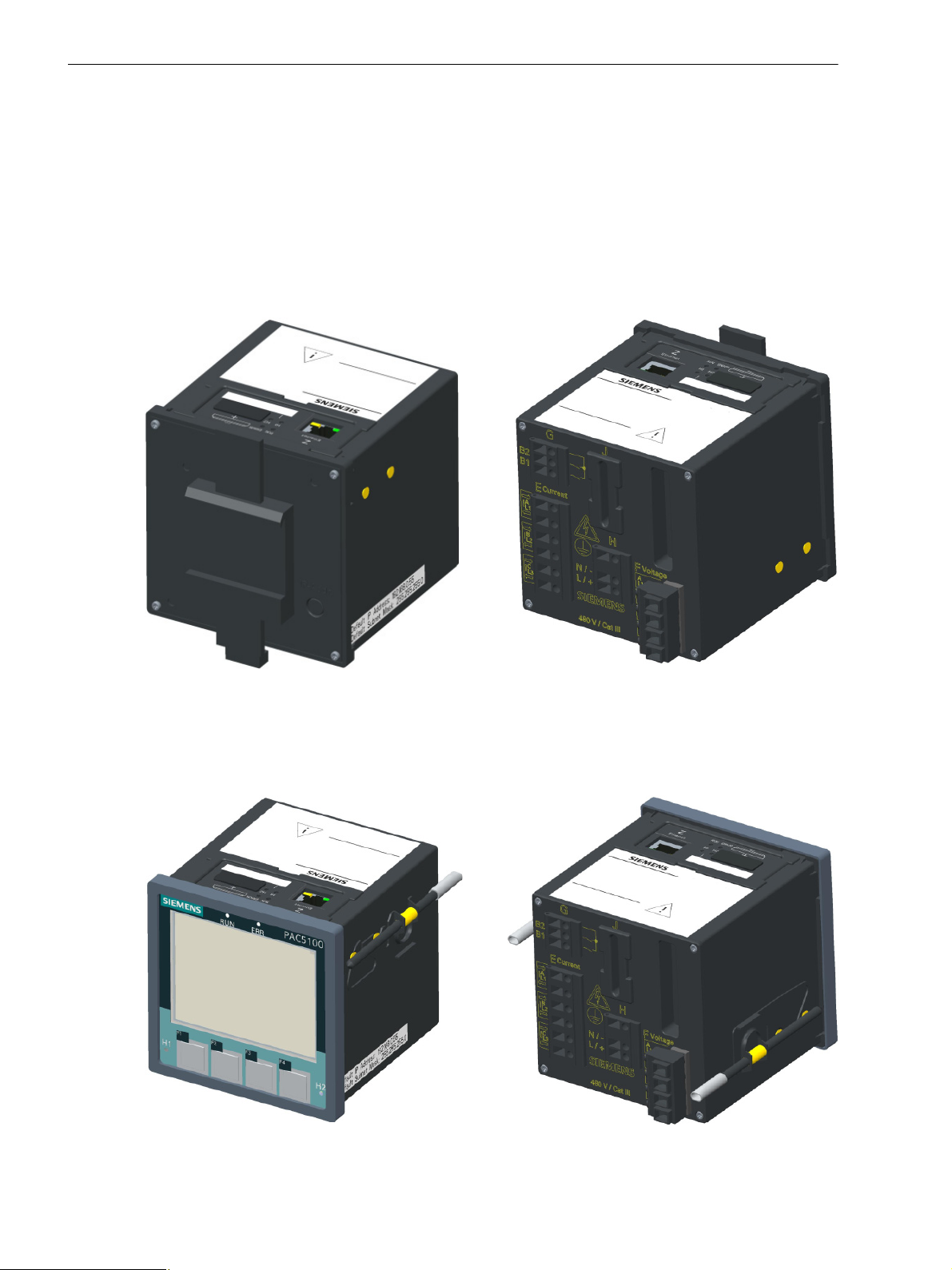
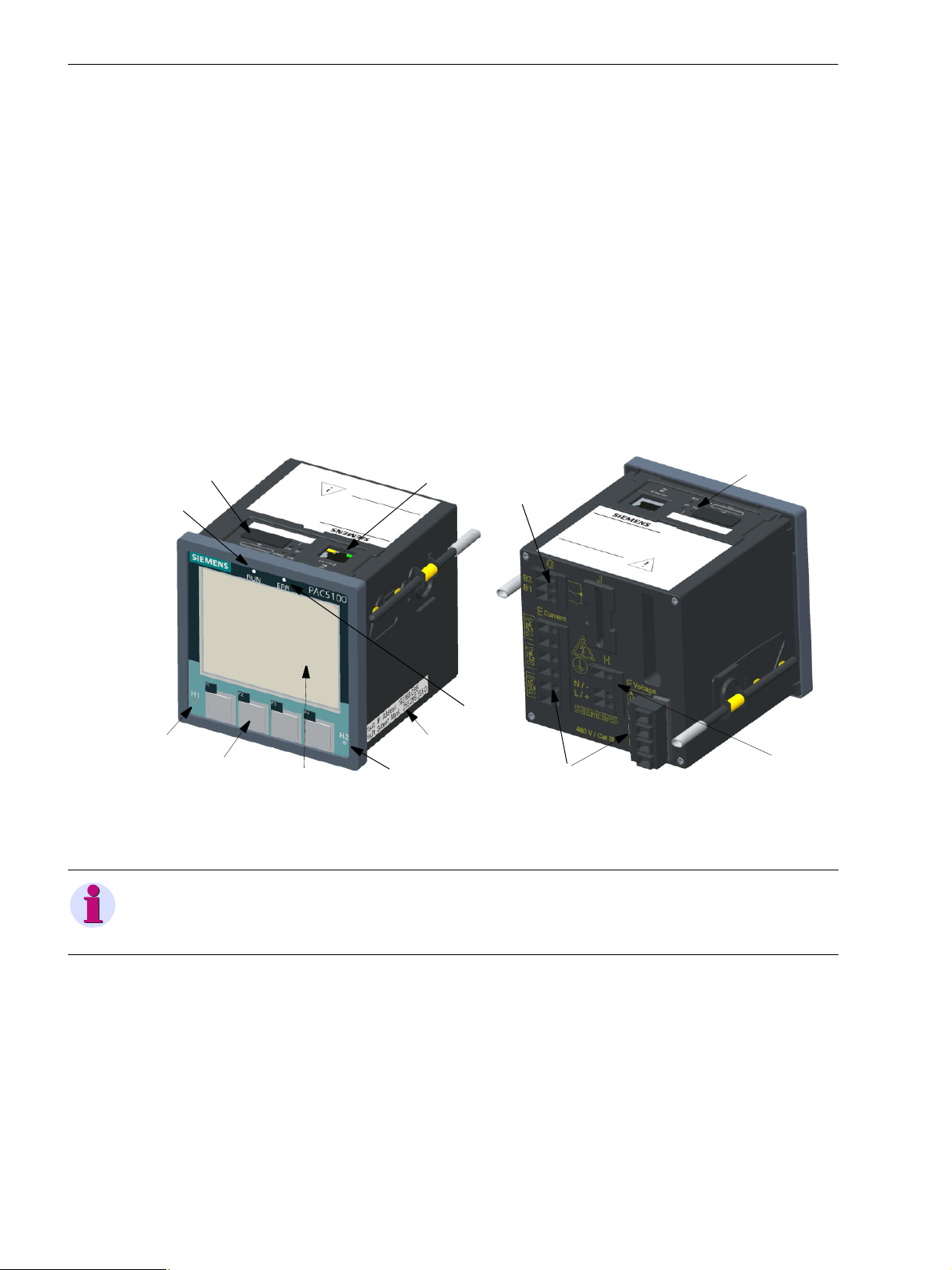
2 Overview
SENTRON PAC5x00 as DIN Rail Device,
SENTRON PAC5x00 as DIN Rail Device,
DIN Rail Side
Terminal Side
SENTRON PAC5x00 for Panel Flush Mounting,
SENTRON PAC5x00 for Panel Flush Mounting,
Display Side
Terminal Side
2.1 Device Versions
2.1 Device Versions
The multifunctional SENTRON PAC5100/5200 devices are used to detect, calculate, evaluate, display, and
transmit measured electrical quantities such as alternating current, alternating voltage, power values etc.
SENTRON PAC5200 devices additionally feature memory options for recorder functions such as mean values,
minimum and maximum values, and fault records.
The properties of the device versions can see you from the ordering information (see Table 2-1) .
SENTRON PAC5x00 Variant, DIN Rail Device
Figure 2-1 SENTRON PAC5x00 Variant, DIN Rail Device
SENTRON PAC5x00 Variant with Graphic Display, Panel Flush Mounting
Figure 2-2 SENTRON PAC5x00 Variant with Graphic Display
18 SENTRON PAC5100/5200, 7KM5212/5412, Device Manual
E50417-H1040-C568-A1, Edition 03.2015

2.2 Ordering Information and Scope of Delivery
2.2 Ordering Information and Scope of Delivery
Ordering Information
Use the following ordering code to order SENTRON PAC5100/5200 devices:
Table 2-1 Ordering Information SENTRON PAC5100/5200
Properties
2 Overview
Device type
Dimensions 96 mm x 96 mm x 100 mm
4 Inputs for AC voltage measurements
3 Inputs for AC current measurements
2 Binary outputs
Galvanic isolated voltage measurement inputs
Web server for parameterization, visualization and data management
Online value visualization
Measurement acc. to standard IEC 61000-4-30, class S
Communication via Ethernet (RJ45) with Modbus TCP protocol
UL Certification
Monitoring, Recording and Power Quality (PQ) Functions
Basic measurements: V, I, f, P, Q, S, cos phi, limit violations, energy
measurements, measurements till 40th harmonics
Basic measurements and advanced measurements:
Power Quality instrument
Measurement min/max/mean values
Recorder for Power Quality measurements
Various recorders for other measurements
Event detection (e.g. Vdip), visualisation
Flicker acc. to IEC 61000-4-15
Online PQ reporting e.g. acc. to EN 50160
Data export acc. to IEEE Std. 1159-3 (PQDIF and COMTRADE data)
Internal memory 2 GB
(SENTRON PAC5100)
7KM5212-6CA00-1EA8
xxxx
xx
(SENTRON PAC5200)
7KM5412-6CA00-1EA8
xx
(SENTRON PAC5100)
7KM5212-6BA00-1EA2
(SENTRON PAC5200)
7KM5412-6BA00-1EA2
Housing and front degree of protection
Snap on mounting unit without graphical display
IP20
Panel mounted instrument with graphical display
IP40
E50417-H1040-C568-A1, Edition 03.2015
xx
xx
19SENTRON PAC5100/5200, 7KM5212/5412, Device Manual

2 Overview
2.2 Ordering Information and Scope of Delivery
Scope of Delivery
The delivery comprises the following components depending on the ordering code:
• SENTRON PAC5100/5200 according to ordering code (see Table 2-1)
• Battery (insulated in the battery compartment of the device)
• Operating instruction
20 SENTRON PAC5100/5200, 7KM5212/5412, Device Manual
E50417-H1040-C568-A1, Edition 03.2015

3 Device Design
3.1 Mechanical Design 22
3.2 Display and Softkeys 23
3.3 Electrical Design 24
E50417-H1040-C568-A1, Edition 03.2015
21SENTRON PAC5100/5200, 7KM5212/5412, Device Manual
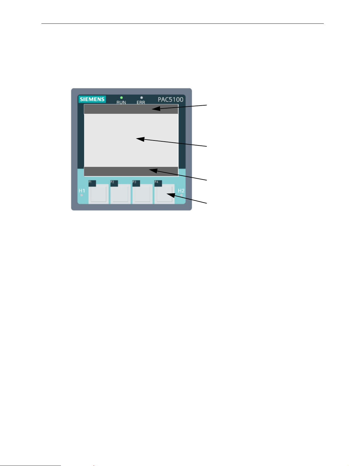
3 Device Design
RJ45 with
4LEDs
2LEDs
Cover of battery
compartment
Terminal block for
Default IP address
Default subnet mask
LED RUN
LED ERROR
LED H1
LED H2
Softkeys
F1 to F4
Terminal blocks for
measurements (voltage, current)
power supply
Terminal block for
binary outputs
Display
Terminal side
Display side
3.1 Mechanical Design
3.1 Mechanical Design
The electrical modules are installed in a plastic case with the dimensions 96 mm x 96 mm x 100 mm
(W x H x D).
In panel flush mounting devices, the display side accommodates the display, 4 softkeys located below and 4
LEDs of which the H1, H2, and ERROR LEDs can be parameterized. The ERROR LED can only be
parameterized for error messages.
The device top side holds the RJ45 Ethernet plug connector with 2 LEDs. 4 additional LEDs are identical to the
LEDs on the display side. At the cover of the battery compartment there is a labeling strip for the configurable
LEDs H1/H2 and a battery symbol that indicates the polarity. The label is also located on the top side and
provides among other information the most important rated data of the device. A lithium battery is located under
the removable cover of the battery compartment.
On the terminal side are available: terminals for all inputs and outputs, terminals for power supply and
protective grounding.
22 SENTRON PAC5100/5200, 7KM5212/5412, Device Manual
Figure 3-1 Layout of the Panel Flush Mounting Version of SENTRON PAC5x00 with Display
NOTE
DIN rail devices have a DIN rail support instead of the display. Therefore, this device side is referred to as the
DIN rail side.
E50417-H1040-C568-A1, Edition 03.2015
3.2 Display and Softkeys
MAX MENU
Voltage ph -n MAX 1.1
n 2.00 V Date/Time
c 229.00 V Date/Time
b 231.00 V Date/Time
a 230.00 V Date/Time
Title
Display area
Softkey functions
Softkeys F1 to F4
Display
The layout of the display is shown in the following figure.
3 Device Design
3.2 Display and Softkeys
Figure 3-2 Display and Softkeys
The top line (title) shows the name of the current display in the display area.
The display area below shows parameter settings, measured values, and graphic pictures.
The bottom line shows the 4 current functions of the softkeys below the display used to set the parameters.
Softkeys
The 4 softkeys on the display side are used to make the desired entries at the device.
To call and activate the IP address, press softkey F4 (for > 3 s, see Figure 3-2) on the right during system
startup if necessary. The IP address and the standard subnet mask are imprinted on the side panel of the device
(see Figure 3-1).
Chapter 8 gives a detailed description of the softkey functions.
E50417-H1040-C568-A1, Edition 03.2015
23SENTRON PAC5100/5200, 7KM5212/5412, Device Manual
3 Device Design
4 x AC
voltage
measuring
inputs
Terminal
Power
supply
Terminal
3 x AC
current
measuring
inputs
Terminal
2 x Binary
outputs
Terminal
ADC
LED Ethernet
DSP
DisplaySoftkeys
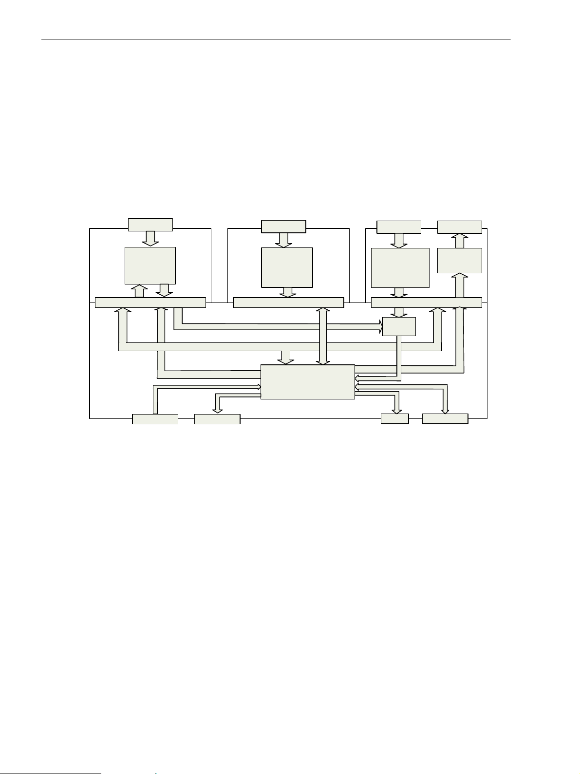
3.3 Electrical Design
3.3 Electrical Design
SENTRON PAC5100/5200 contains the following electrical modules:
• Digital signal processor (DSP)
• Display and Softkeys (optional)
• 4 inputs for alternating voltage measurements
• 3 inputs for alternating current measurements
• 2 binary outputs
• Supply voltage
• Ethernet interface
Figure 3-3 Block Diagram SENTRON PAC5x00 with Display (Optional)
24 SENTRON PAC5100/5200, 7KM5212/5412, Device Manual
E50417-H1040-C568-A1, Edition 03.2015

4 Measurands and Recording
4.1 Measuring and Recording System 26
4.2 Measurands 39
4.3 Display of Measurands 64
E50417-H1040-C568-A1, Edition 03.2015
25SENTRON PAC5100/5200, 7KM5212/5412, Device Manual
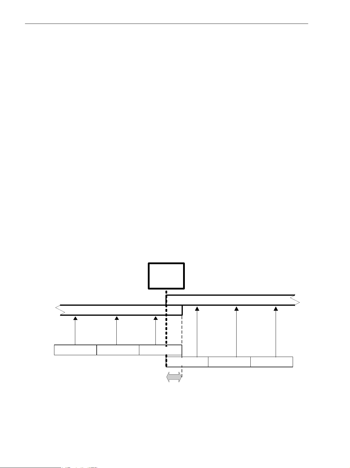
4 Measurands and Recording
RTC
10-minute
limit
k
10-minute interval (x+1)
j
10/12 periods
i
1
2 3
Overlapping area
10-minute interval (x)
10/12 periods
10/12 periods 10/12 periods
10/12 periods
10/12 periods
4.1 Measuring and Recording System
4.1 Measuring and Recording System
4.1.1 Functioning of the Measuring System according to IEC 61000-4-30
SENTRON PAC5100/5200 devices measure the power quality according to IEC 61000-4-30 in 1-phase or
multi-phase distribution systems. The measuring system is implemented according to class A. In terms of
functional scope, measuring ranges, and accuracy, the SENTRON PAC5100/5200 devices are class S.
The basic measuring interval for determining the values for mains voltage, harmonics of mains voltage, and
mains voltage unbalance is a 10-period time interval for 50-Hz distribution systems or a 12-period time interval
for 60-Hz distribution systems. The measurement of the 10-/12-period time intervals is resynchronized at each
RTC 10-minute limit.
Subsequently, the values for the 10-/12-period time intervals are aggregated over additional time intervals (for
example, 10-minute interval at SENTRON PAC5200).
10-Minute Interval (SENTRON PAC5200)
The value aggregated in a 10-minute interval is tagged with the absolute time (for example 01:10:00). The time
at the end of the aggregation interval is indicated as the time qualifier. The values for the 10-minute time interval
are calculated without interruption from the 10-/12-period time intervals.
• Each 10-minute interval begins at an RTC 10-minute limit. At this 10-minute limit, the 10-/12-period time
intervals are aggregated over a 10-minute interval. The last 10-/12-period time interval in a 10-minute
aggregation interval overlaps in time at an RTC 10-minute limit. Each overlapping 10-/12-period time
interval (for the overlapping area, see Figure 4-1) is included in the aggregation interval of the preceding
10-minute interval.
• The aggregation interval enables the power system quality to be evaluated according to EN 50160. The
aggregation interval can be adjusted to other applications using a parameter. A shorter aggregation
interval increases the storage capacity required for measured values and reduces the maximum possible
recording time in the memory.
26 SENTRON PAC5100/5200, 7KM5212/5412, Device Manual
Figure 4-1 Synchronization of the Aggregation Intervals for Class A
E50417-H1040-C568-A1, Edition 03.2015

Flagging Concept
During conditions of undervoltage, overvoltage, or voltage interruption, the measurement method can return
implausible values for other measurands (for example, frequency measurement, voltage harmonics). The
flagging concept therefore prevents an individual event from being accounted for multiple times in different
measurands (for example, a single undervoltage event both as undervoltage and simultaneously as a
frequency change).
Flaggings are only triggered by undervoltage, overvoltage, and voltage interruptions. Undervoltage and
overvoltage detection is based on a threshold value selected by the user. This value determines whether data
are flagged.
The flagging concept is used when measuring the power frequency, mains voltage, mains voltage unbalance,
and harmonics of the mains voltage.
If a value was flagged within a given time interval, the aggregated value containing that value will be flagged,
too. Flagged values are stored and optionally integrated in the calculation or hidden.
Table 4-1 Overview of the Measurands to Determine the Power Quality
4 Measurands and Recording
4.1 Measuring and Recording System
Measurand Method of
Measurement Uncertainty and
Measurement
Power frequency Class A Class S
±50 mHz in the measuring ranges:
50 Hz: 42.5 Hz to 57.5 Hz
60 Hz: 51.0 Hz to 69.0 Hz
Mains voltage level Class A Class S
smaller than ±0.5 % Udin in the
range from 20 % Udin to 120 % Udin
Undervoltages and
overvoltages of the mains
Class A Class S
±1.0 % of Udin, 1 period
voltage,
Voltage interruptions
Unbalance of the mains
voltage
Class A Class S
U
and U0 smaller than ±0.3 % in the
2
range
1 % to 5 % U
Harmonics of the mains
voltage
Class A Class S
Vm > 3 % Udin: ±5% V
Vm < 3 % Udin: ±0.15 % Udin
10 % to 100 % of the compatibility
levels of class 3 or IEC 61000-2-4
Measurement uncertainty:
Measuring range 200 %,
IEC 61000-4-7, Class 2
Measuring Range
, U
2
1
m
SENTRON
Flagging
PAC5100/5200
50 mHz
(see Table 4-17)
0.2 % x
0.2 % -
0.2 % x
Condition:
10 % V
V
m
rated
Maximum error:
±5 % V
m
----------------------Condition:
Vm < 10 % V
rated
Maximum error:
±0.5 % V
rated
x
x
Flicker Class A Class S
IEC 61000-4-30:
Pst: ±10 %
Pst: ±10 %
Plt: ±10 %
Pinst: ±16 %
-
Plt: ±10 %
Pinst: ±16 %
Udin: Declared input voltage (The primary nominal voltage is used for it in the SENTRON PAC5100/5200. At use of a
voltage converter the primary nominal voltage and the secondary nominal voltage of the transducer are used.)
: Measured value
V
m
V
: Rated voltage
rated
E50417-H1040-C568-A1, Edition 03.2015
27SENTRON PAC5100/5200, 7KM5212/5412, Device Manual
4 Measurands and Recording
-70
-60
-50
-40
-30
-20
-10
0
10
20
30
40
50
60
70
V [V]
44,85 44,90 44,95
t [s]
V
rms
(1/2) :
RMS value over one period synchronized to the zero point of the fundamental
component, updated after each half period .
This value is only used to detect undervoltages , overvoltages and voltage
interruptions .
V
rms
n
n+1
n+2
n+3
n+4
n+5
n+6
n+7
n+8
n+ 9
n+10
V
rms
V
rms
V
rms
V
rms
V
rms
V
rms
V
rms
V
rms
V
rms
V
rms
4.1 Measuring and Recording System
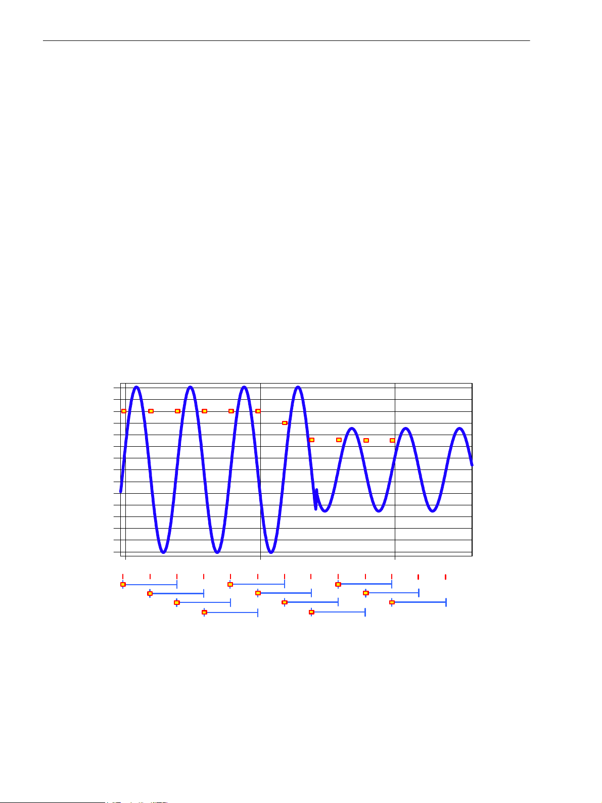
Definition of the Measurands
Mains Voltage Level
• The measurement determines the RMS value of the mains voltage over a 10-period time interval for 50Hz distribution systems and over a 12-period time interval for 60-Hz distribution systems. All 10-/12-period
time intervals are measured without interruption and overlapping (the overlapping area excluded, see
Figure 4-1).
Undervoltage of the Mains Voltage
• The basic measurement of the RMS value V
V
(1/2) for each single measuring channel (see Figure 4-2). The limiting value for undervoltages is a
rms
percentage value of Udin.
• The factory setting of the hysteresis is 2 % of Udin. It can be set from 1 % to 6 %.
• In multi-phase systems, all channels are independently synchronized in the zero point of the voltage.
• In 1-phase systems, undervoltage begins when the voltage V
undervoltage. Undervoltage ends when the voltage V
undervoltage plus the hysteresis.
• In multi-phase systems, undervoltage begins when the voltage V
undervoltage in one or more channels. Undervoltage ends when the voltage V
threshold value of the undervoltage plus the hysteresis in all measured channels.
• The undervoltage threshold value and the hysteresis are parameterized according to the measuring task.
• Undervoltage is characterized by the data pair residual voltage (V
The residual voltage is the smallest voltage value of V
undervoltage.
of an undervoltage is the determination of the RMS value
rms
falls below the threshold of the
rms
rises above the threshold value of the
rms
falls below the threshold of the
rms
) and duration (t):
res
which is measured in a channel during
rms
rises above the
rms
28 SENTRON PAC5100/5200, 7KM5212/5412, Device Manual
Figure 4-2 Undervoltage Representation
E50417-H1040-C568-A1, Edition 03.2015

4 Measurands and Recording
4.1 Measuring and Recording System
Overvoltage of the Mains Voltage
• The basic measurement of the RMS value V
V
(1/2) for each single measuring channel. The limiting value for overvoltages is a percentage value of
rms
of overvoltage is the determination of the RMS value
rms
Udin.
• The factory setting of the hysteresis is 2 % of Udin. It can be set from 1 % to 6 %.
• In multi-phase systems, all channels are independently synchronized in the zero point of the voltage.
• In 1-phase systems, overvoltage begins when the voltage V
overvoltage. Overvoltage ends when the voltage V
falls below the threshold value of the overvoltage
rms
rises above the threshold of the
rms
minus the hysteresis.
• In multi-phase systems, overvoltage begins when the voltage V
overvoltage in one or more channels. Overvoltage ends when the voltage V
rises above the threshold of the
rms
falls below the threshold
rms
value of the overvoltage minus the hysteresis in all measured channels.
• The overvoltage threshold value and the hysteresis were parameterized according to the measuring task.
• Overvoltage is characterized by the data pair Maximum value of overvoltage and duration (t):
The maximum value of an overvoltage is the highest voltage value of V
which is measured in a channel
rms
during overvoltage.
Voltage Interruption
• In 1-phase systems, a voltage interruption begins when the voltage V
voltage interruption. The voltage interruption ends when the voltage V
falls below the threshold of the
rms
rises above the threshold value
rms
of the voltage interruption plus the hysteresis.
• In multi-phase systems, the voltage interruption begins when the voltages V
the voltage interruption in all channels. The voltage interruption ends when the voltage V
fall below the threshold of
rms
rises above
rms
the threshold value of the voltage interruption plus the hysteresis in any of the measured channels.
• The voltage interruption threshold value and the hysteresis are parameterized according to the measuring
task.
• The factory setting of the hysteresis is 2 % of Udin. It can be set from 1 % to 6 %.
Unbalance of the Mains Voltage
• The mains voltage unbalance is determined using the method of the symmetrical components. In case of
unbalance, the negative-sequence component U2 is determined in addition to the positive-sequence
component U
. The fundamental component of the voltage is measured over a 10-period time interval for
1
50-Hz distribution systems and over a 12-period time interval for 60-Hz distribution systems.
Harmonics of the Mains Voltage
• interruption-free 10-/12-period measurement of a harmonics subgroup U
according to
sg,n
IEC 61000-4-7.
• The total distortion is calculated as the subgroup total harmonic distortion (THDS) according to IEC 610004-7.
• Measurements are performed up to the 40th harmonics order.
E50417-H1040-C568-A1, Edition 03.2015
29SENTRON PAC5100/5200, 7KM5212/5412, Device Manual

4 Measurands and Recording
4.1 Measuring and Recording System
Flicker
• The short-term flicker value Pst and long-term flicker value Plt are determined for phase-to-ground voltages and delta voltages. The flicker measurement is performed according to EN 61000-4-15.
• The flicker measurement is performed on all 3 voltage channels.
• Flickers appear with a frequency from 0.005 to 35 Hz. The instantaneous flicker value is displayed in perceptibility units P.
• Short-term flicker value Pst
determined over 10 min (short-term flicker), fixed
• Long-term flicker value Plt
over 2 h (12 Pst values), fixed
• Perceptibility Pinst
30 SENTRON PAC5100/5200, 7KM5212/5412, Device Manual
E50417-H1040-C568-A1, Edition 03.2015
 Loading...