

Siemens SENTRON PAC4200 User Manual
PAC4200

SENTRON
Power Monitoring Device
PAC4200
System Manual
05/2019
A5E02316180B
Introduction
1
Description
2
Installation
3
Connection
4
Commissioning
5
Operation
6
Parameterizing
7
Service and maintenance
8
Technical data
9
Dimensional drawings
10
Appendix
A
List of abbreviations
B
-05

Siemens AG
Smart Infrastructure
Low Voltage Products
Postfach 10 09 53
93009 REGENSBURG
GERMANY
Document order number: 3ZX1012-0KM42-3AC0
Ⓟ
Copyright © Siemens AG 2008.
All rights rese
DANGER
indicates that death or severe personal injury will result if proper precautions are not taken.
WARNING
indicates that death or severe personal injury may result if proper precautions are not taken.
CAUTION
indicates that minor personal injury can result if proper precautions are not taken.
NOTICE
indicates that property damage can result if proper precautions are not taken.
WARNING
Siemens products may only be used for the applications described in the catalog and in the relevant technical
ambient conditions must be complied with. The information in the relevant documentation must be observed.
Legal information
Warning notice system
This manual contains notices you have to observe in order to ensure your personal safety, as well as to prevent
damage to property. The notices referring to your personal safety are highlighted in the manual by a safety alert
symbol, notices referring only to property damage have no safety alert symbol. These notices shown below are
graded according to the degree of danger.
If more than one degree of danger is present, the warning notice representing the highest degree of danger will
be used. A notice warning of injury to persons with a safety alert symbol may also include a warning relating to
property damage.
Qualified Personnel
The product/system described in this documentation may be operated only by personnel qualified for the specific
task in accordance with the relevant documentation, in particular its warning notices and safety instructions.
Qualified personnel are those who, based on their training and experience, are capable of identifying risks and
avoiding potential hazards when working with these products/systems.
Proper use of Siemens products
Note the following:
documentation. If products and components from other manufacturers are used, these must be recommended
or approved by Siemens. Proper transport, storage, installation, assembly, commissioning, operation and
maintenance are required to ensure that the products operate safely and without any problems. The permissible
Trademarks
All names identified by ® are registered trademarks of Siemens AG. The remaining trademarks in this publication
may be trademarks whose use by third parties for their own purposes could violate the rights of the owner.
Disclaimer of Liability
We have reviewed the contents of this publication to ensure consistency with the hardware and software
described. Since variance cannot be precluded entirely, we cannot guarantee full consistency. However, the
information in this publication is reviewed regularly and any necessary corrections are included in subsequent
editions.
05/2019 Subject to change
rved

Table of contents
1 Introduction ............................................................................................................................................. 7
1.1 Components of the product ...................................................................................................... 7
1.2 Latest information ..................................................................................................................... 7
1.3 Security information .................................................................................................................. 9
2 Description ............................................................................................................................................ 11
2.1 Performance features ............................................................................................................. 11
2.2 Measuring inputs ..................................................................................................................... 16
2.3 Measured variables ................................................................................................................. 18
2.3.1 Sliding window demands ........................................................................................................ 21
2.3.2 Averaging measured values (aggregation) ............................................................................. 22
2.3.3 Other properties of measured variable representation ........................................................... 22
2.4 Load profile ............................................................................................................................. 23
2.4.1 Historical load profile............................................................................................................... 27
2.4.2 Current load profile data at the communication interfaces ..................................................... 28
2.4.3 Synchronization of the load profile .......................................................................................... 29
2.4.4 Additional information about the load profile data .................................................................. 30
2.5 Tariffs ...................................................................................................................................... 30
2.6 Technical features of the network quality ............................................................................... 31
2.7 Date and time .......................................................................................................................... 33
2.8 Limit values ............................................................................................................................. 34
2.9 Function of the digital inputs and outputs ............................................................................... 35
2.9.1 Digital output ........................................................................................................................... 35
2.9.2 Digital input ............................................................................................................................. 37
2.10 Ethernet interface .................................................................................................................... 38
2.11 Slots for expansion modules ................................................................................................... 39
2.12 Gateway .................................................................................................................................. 40
2.13 Insertion openings ................................................................................................................... 42
2.14 User-definable displays........................................................................................................... 43
3 Installation ............................................................................................................................................ 45
3.1 Introduction ............................................................................................................................. 45
3.2 Inserting the battery ................................................................................................................ 47
3.3 Tools ....................................................................................................................................... 48
3.4 Mounting on the switching panel ............................................................................................ 48
3.4.1 Mounting dimensions .............................................................................................................. 48
3.4.2 Installation steps ..................................................................................................................... 49
PAC4200
System Manual, 05/2019, A5E02316180B-05
3

Table of contents
3.5 Deinstallation .......................................................................................................................... 51
4 Connection ........................................................................................................................................... 53
4.1 Safety information .................................................................................................................. 53
4.2 Connections ........................................................................................................................... 55
4.3 Connection examples ............................................................................................................ 58
4.4 Grounding of the Ethernet cable ............................................................................................ 65
5 Commissioning ..................................................................................................................................... 67
5.1 Overview ................................................................................................................................ 67
5.2 Applying the supply voltage ................................................................................................... 68
5.3 Parameterizing the device ..................................................................................................... 69
5.3.1 First start-up ........................................................................................................................... 69
5.3.2 Basic parameters ................................................................................................................... 70
5.3.3 Additional settings .................................................................................................................. 71
5.4 Applying the measuring voltage ............................................................................................. 71
5.5 Applying the measuring current ............................................................................................. 72
5.6 Checking the displayed measured values ............................................................................. 72
6 Operation .............................................................................................................................................. 73
6.1 Device interface ..................................................................................................................... 73
6.1.1 Displays and operator controls .............................................................................................. 73
6.1.2 Special display elements ....................................................................................................... 74
6.1.3 Menu-based navigation .......................................................................................................... 75
6.1.4 Measured value level ............................................................................................................. 75
6.1.5 Main menu level ..................................................................................................................... 76
6.1.6 Setting level ............................................................................................................................ 76
6.1.7 Editing level ............................................................................................................................ 76
6.1.8 Control keys ........................................................................................................................... 77
6.2 Special displays ..................................................................................................................... 79
6.2.1 Phasor diagram ...................................................................................................................... 79
6.2.2 Measurement of 1st to 64th harmonics for voltage and current ............................................ 80
6.2.3 Events .................................................................................................................................... 82
6.3 Supporting software ............................................................................................................... 86
6.3.1 SENTRON powermanager .................................................................................................... 86
6.3.2 SENTRON powerconfig ......................................................................................................... 87
6.3.3 Web server ............................................................................................................................. 87
7 Parameterizing ...................................................................................................................................... 89
7.1 Introduction ............................................................................................................................ 89
7.2 Parameterizing via the user interface .................................................................................... 90
7.2.1 Parameterizing via the user interface .................................................................................... 90
7.2.2 Device information ................................................................................................................. 91
7.2.3 Language/Regional ................................................................................................................ 91
7.2.4 Basic parameters ................................................................................................................... 91
7.2.5 Power demand ....................................................................................................................... 95
7.2.6 Date/time ................................................................................................................................ 95
PAC4200
4 System Manual, 05/2019, A5E02316180B-05

Table of contents
7.2.7 Integrated I/Os ........................................................................................................................ 97
7.2.8 Communication ..................................................................................................................... 101
7.2.9 Display .................................................................................................................................. 103
7.2.10 Advanced .............................................................................................................................. 104
7.3 Protection against manipulation ............................................................................................ 111
7.3.1 Introduction ........................................................................................................................... 111
7.3.2 Password protection ............................................................................................................. 112
7.3.3 Hardware write protection ..................................................................................................... 114
7.3.4 Device access control (IP filter) ............................................................................................ 117
7.3.5 Configuring the Modbus TCP port ........................................................................................ 119
8 Service and maintenance .................................................................................................................... 121
8.1 Calibration ............................................................................................................................. 121
8.2 Cleaning ................................................................................................................................ 121
8.3 Firmware update ................................................................................................................... 122
8.4 Replacing the battery ............................................................................................................ 123
8.5 Repair ................................................................................................................................... 126
8.6 Disposal ................................................................................................................................ 126
9 Technical data .................................................................................................................................... 127
9.1 Technical data ....................................................................................................................... 127
9.2 Labeling ................................................................................................................................ 138
10 Dimensional drawings ......................................................................................................................... 141
A Appendix............................................................................................................................................. 145
A.1 Load profile ........................................................................................................................... 145
A.2 Modbus ................................................................................................................................. 145
A.2.1 Measured variables without a time stamp with the function codes 0x03 and 0x04 .............. 146
A.2.2 Structure – Digital inputs status and digital outputs status with the function codes 0x01
and 0x02 ............................................................................................................................... 153
A.2.3 Structure – Limit values with the function codes 0x01 and 0x02 .......................................... 154
A.2.4 Structure – PMD diagnostics and status with the function codes 0x03 and 0x04 ................ 155
A.2.5 Measured variables for the load profile with the function codes 0x03 and 0x04 .................. 156
A.2.6 Tariff-specific energy values in double format with the function codes 0x03, 0x04, and
0x10 ...................................................................................................................................... 159
A.2.7 Tariff-specific energy values in float format with the function codes 0x03 and 0x04 ........... 160
A.2.8 Maximum values with a time stamp and the function codes 0x03 and 0x04........................ 161
A.2.9 Minimum values with a time stamp and the function codes 0x03 and 0x04......................... 165
A.2.10 Odd harmonics without a time stamp with the function codes 0x03 and 0x04 ..................... 168
A.2.11 Odd harmonics with a time stamp with the function codes 0x03 and 0x04 .......................... 170
A.2.12 Readout of harmonic components of all harmonics with function codes 0x03, 0x04 and
0x14 ...................................................................................................................................... 172
A.2.13 Readout of averages (aggregation) with function codes 0x03, 0x04 and 0x14.................... 175
A.2.14 Configuration settings with the function codes 0x03, 0x04, and 0x10 .................................. 192
A.2.15 Value range for limit source .................................................................................................. 201
A.2.16 Communication settings with the function codes 0x03, 0x04, and 0x10 .............................. 207
A.2.17 I&M settings .......................................................................................................................... 210
A.2.18 Commands with the function code 0x06 ............................................................................... 211
PAC4200
System Manual, 05/2019, A5E02316180B-05
5

Table of contents
A.2.19 MODBUS standard device identification with the function code 0x2B ................................ 212
A.3 Comprehensive support from A to Z .................................................................................... 213
B List of abbreviations ............................................................................................................................. 215
B.1 Abbreviations ....................................................................................................................... 215
Glossary .............................................................................................................................................. 217
Index ................................................................................................................................................... 219
PAC4200
6 System Manual, 05/2019, A5E02316180B-05

1
1.1 Components of the product
The package includes:
● 1 PAC4200 measuring device
● 1 battery
● 2 brackets for panel mounting
● 1 set of PAC4200 Operating Instructions
Available accessories
● powerconfig software
(https://support.industry.siemens.com/cs/ww/en/view/63452759
)
● powermanager software
(https://support.industry.siemens.com/cs/ww/en/view/64850998
1.2 Latest information
Up-to-the-minute information
You can find further support on the Internet (http://www.siemens.de/lowvoltage/technical-
assistance).
Third-party software information
This product, solution or service ("Product") contains third-party software components listed
in this document. These components are Open Source Software licensed under a license
approved by the Open Source Initiative (https://opensource.org/
determined by SIEMENS ("OSS") and/or commercial or freeware software components. With
respect to the OSS components, the applicable OSS license conditions prevail over any
other terms and conditions covering the Product. The OSS portions of this Product are
provided royalty-free and can be used at no charge.
If SIEMENS has combined or linked certain components of the Product with/to OSS
components licensed under the GNU LGPL version 2 or later as per the definition of the
applicable license, and if use of the corresponding object file is not unrestricted ("LGPL
Licensed Module", whereas the LGPL Licensed Module and the components that the LGPL
Licensed Module is combined with or linked to is the "Combined Product"), provided the
relevant LGPL license criteria are met, you are entitled to modify the Combined Product for
your own use, including but not limited to the right to modify the Combined Product to relink
modified versions of the LGPL Licensed Module, and you may reverse-engineer the
)
), or similar licenses as
PAC4200
System Manual, 05/2019, A5E02316180B-05
7

Introduction
1.2 Latest information
Combined Product, but only to debug your modifications. The modification right does not
include the right to distribute such modifications and you shall maintain in confidence any
information resulting from such reverse-engineering of a Combined Product.
Certain OSS licenses require SIEMENS to make source code available, for example, the
GNU General Public License, the GNU Lesser General Public License and the Mozilla Public
License. If such licenses are applicable and this Product is not shipped with the required
source code, a copy of this source code can be obtained by anyone in receipt of this
information during the period required by the applicable OSS licenses by contacting the
following address:
Siemens AG Energy Management, Low Voltage & Products
Siemensstrasse 10
93055 Regensburg
Germany
Internet:
Technical Assistance (www.siemens.de/lowvoltage/support-request
)
Subject: Open Source Request (please specify Product name and version, if applicable)
SIEMENS may charge a handling fee of up to 5 EUR to fulfil the request.
Warranty regarding further use of the Open Source Software
SIEMENS' warranty obligations are set forth in your agreement with SIEMENS. SIEMENS
does not provide any warranty or technical support for this Product or any OSS components
contained in it if they are modified or used in any manner not specified by SIEMENS. The
license conditions listed below may contain disclaimers that apply between you and the
respective licensor. For the avoidance of doubt, SIEMENS does not make any warranty
commitment on behalf of or binding upon any third-party licensor.
PAC4200
8 System Manual, 05/2019, A5E02316180B-05

Introduction
Note
Risk of manipulation
Several protective mechanisms can be activated in the device.
In order to red
the protective mechanisms available in the device are activated.
See chapter
DANGER
Hazardous voltage.
Will cause death or serious injury.
1.3 Security information
1.3 Security information
Siemens provides products and solutions with industrial security functions that support the
secure operation of plants, systems, machines and networks.
In order to protect plants, systems, machines and networks against cyber threats, it is
necessary to implement – and continuously maintain – a holistic, state-of-the-art industrial
security concept. Siemens’ products and solutions constitute one element of such a concept.
Customers are responsible for preventing unauthorized access to their plants, systems,
machines and networks. Such systems, machines and components should only be
connected to an enterprise network or the Internet if and to the extent such a connection is
necessary and only when appropriate security measures (e.g. firewalls and/or network
segmentation) are in place.
For additional information on industrial security measures that may be implemented, please
visit (https://www.siemens.com/industrialsecurity
Siemens’ products and solutions undergo continuous development to make them more
secure. Siemens strongly recommends that product updates are applied as soon as they are
available and that the latest product versions are used. Use of product versions that are no
longer supported, and failure to apply the latest updates may increase customer's exposure
to cyber threats.
).
To stay informed about product updates, subscribe to the Siemens Industrial Security RSS
Feed under (https://www.siemens.com/industrialsecurity
General safety notes
Turn off and lock out all power supplying this equipment before working on this device.
).
uce the risk of manipulation occurring on the device, it is recommended that
Performance features (Page 11).
PAC4200
System Manual, 05/2019, A5E02316180B-05
9
Introduction
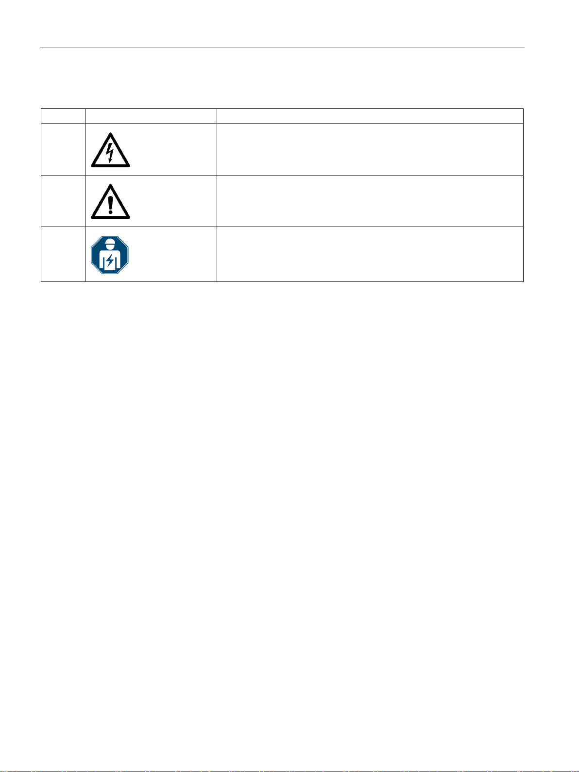
Symbol
Meaning
1.3 Security information
Safety-related symbols on the device
(1)
(2)
(3)
See also
Risk of electric shock
General warning symbol
Electrical installation and maintenance by qualified personnel only
Applying the measuring current (Page 72)
Applying the measuring voltage (Page 71)
Applying the supply voltage (Page 68)
Replacing the battery (Page 123)
Password protection (Page 112)
PAC4200
10 System Manual, 05/2019, A5E02316180B-05

2
2.1 Performance features
The SENTRON PAC4200 is a measuring device for measuring the basic electrical variables
in low-voltage power distribution. The device is capable of single-phase, two-phase or threephase measurement and can be used in 2, 3 or 4-wire TN, TT and IT systems.
The SENTRON PAC42000 is designed for panel mounting. It is also possible to mount it on
a standard rail using the standard rail support brackets available as an option.
Thanks to its large measuring voltage range, SENTRON PAC4200 with a wide-voltage
power supply can be connected in any low-voltage system up to a rated system voltage of
690 V (max. 600 V for UL). The device version with an extra-low voltage power supply can
be directly connected to systems up to 500 V. Higher voltages can be measured using
voltage transformers.
Either x/1 A or x/5 A current transformers can be used for measuring current.
Measurement
The large graphical display is used to read off all the measured values and to configure the
device.
The integral Ethernet interface or the interface of an expansion module available as an
option can be used for communication, e.g. SENTRON PAC RS485 expansion module or
SENTRON PAC PROFIBUS DP expansion module or PAC SWITCHED ETHERNET module
(Profinet). The functions of the device can be expanded using other expansion modules
available as options. The SENTRON PAC4200 has two interfaces which can accommodate
up to two external expansion modules simultaneously.
● Measurement in 2, 3 and 4-wire systems Suitable for TN, TT and IT systems
● Measurement of all relevant electrical variables in an AC system
● Measurement of minimum and maximum values of all measured variables
● Calculation of genuine RMS values for voltage and current to the 63rd harmonic
● 4-quadrant measurement (import and export)
● Averaging of all measured values directly on the device in two steps, which are
independent of each other and freely configurable (aggregation)
● Measurement of the 1st to 64th harmonics (even and odd)
● Calculation of the average voltage and current values over all phases.
● Zero blind measurement
● High measuring accuracy: for instance, accuracy class 0.2 in accordance with IEC 61557-
12 for active energy This means: an accuracy of 0.2% relative to the measured value
under reference conditions
PAC4200
System Manual, 05/2019, A5E02316180B-05
11

Description
2.1 Performance features
● Detection of voltage dips, overvoltage and voltage interruptions with user-defined
threshold values
● Measurement of N (neutral) conductor current
1)
● Measurement of residual current and PE conductor current through external summation
current transformer
● Measurement of physical variables (e.g. temperature, pressure, humidity) with external
0/4 mA to 20 mA transmitter
1)
Using optionally available expansion module "I(N), I(DIFF), Analog" (MLFB: 7KM92000AD00-0AA0)
Manual 7KM PAC expansion module I(N), I(Diff), analog
(https://support.industry.siemens.com/cs/ww/en/view/109746834
Counters and power demand
● A total of 10 energy counters capture reactive energy, apparent energy, and active
energy for off-peak and on-peak, import and export.
● Energy consumption for active energy, reactive energy and apparent energy per day and
tariff for 366 days.
● Two configurable universal counters for counting:
– Limit violations
– Status changes at the digital input
– Status changes at the digital output
– Pulses of a connected pulse encoder (e.g. from electricity, gas, or water meters). The
pulse shape and time response must correspond to the signal shape described in the
IEC 62053-31 standard.
1)
1)
)
● Operating hours counter for monitoring the operating time of a connected load. Counts
only in the case of energy counting above an adjustable threshold.
● One apparent energy counter, one active energy counter, and one reactive energy
counter for detecting the total energy import, regardless of the active tariff for display on
the device.
● One apparent energy counter, one active energy counter, and one reactive energy
counter for detecting the power consumption of a manufacturing process. The process
energy counters can be started and stopped by means of the available digital inputs.
● Operating hours counter for recording the duration of a manufacturing process. The start
and stop commands of the digital input that controls the process energy counter start and
stop the operating hours counter. Up to 10 counters for detecting the consumption of any
media via digital inputs if the optionally available SENTRON PAC 4DI/2DO expansion
modules are used. Consumption (e.g. of gas, water, compressed air, electrical current)
can thus be recorded using simple media counters with a pulse output.
The display texts can be freely parameterized in a user-friendly way using the
SENTRON powerconfig configuration software.
PAC4200
12 System Manual, 05/2019, A5E02316180B-05

Description
2.1 Performance features
Monitoring functions
The SENTRON PAC4200 monitors up to 12 limit values as well as one limit that can be
formed by logically combining the other 12 limits.
Event display
● Recording up to 4096 events with a time stamp and event-specific information
● Display of events in an events list
● Reporting of events on the display
● Classifying of messages as follows:
– Information
– Warning
– Alarm
Displays and controls
Interfaces
● LC display
● Four control keys with variable function assignment
● SENTRON powerconfig
● SENTRON powermanager
● Web server (HTTP)
● Ethernet
● Two multifunctional integral digital inputs
● Two multifunctional integral digital outputs
● RS 485 (if SENTRON PAC RS485 expansion module is used)
● PROFIBUS (if SENTRON PAC PROFIBUS DP expansion module is used)
● Optionally up to 8 plug-in digital inputs
● Optionally up to 4 plug-in digital outputs
● Two slots for operating optional expansion modules
1)
The SENTRON PAC4200 supports two expansion modules. One of these may be a
1)
communication module (e.g. SENTRON PAC PROFIBUS DP or SENTRON PAC RS485).
PAC4200
System Manual, 05/2019, A5E02316180B-05
13

Description
2.1 Performance features
Gateway
● Modbus gateway for integrating pure Modbus RTU slaves into an Ethernet network
(Ethernet Modbus TCP ⇔ RS 485 Modbus RTU).
● Serial gateway for connecting RS 485 devices that support Modbus RTU and similar
protocols.
Memory
● Adjusted device parameters are permanently stored in the device memory.
● Extreme values (maximum or minimum) are permanently stored in the internal device
memory. Values can be reset via SENTRON powerconfig, Modbus command or directly
on the device via the menu.
● Device-internal clock (battery buffered)
● Storage of load profiles (battery buffered)
● Storage of events (battery buffered)
Response in the case of power failure and power restore
After a power failure, the device starts back at zero with the calculation of the power demand
of the total active power and total reactive power. Counter statuses and minimum/maximum
values are written from the volatile to the non-volatile memory at the following intervals:
● Counter values: Every 5 minutes
● Minimum/maximum values: Every 5 seconds, if present
Tariffs
SENTRON PAC4200 supports 2 tariffs for the integrated energy counter (on-peak and offpeak).
● Control of tariff switching
Switching between off-peak and on-peak can be controlled via the digital input or the
communication interfaces.
Time-related switching is only possible using a higher-level system.
● Tariff switching after synchronization
When synchronizing the power demand values via the communication interfaces or the
digital input, the tariff change will only become effective after expiry of the period. Without
synchronization, the tariff change takes effect immediately.
The synchronization frame contains the length of the demand period in minutes. The
synchronization command is ignored if the period length sent to the device with the
synchronization frame is different to the length parameterized in the device.
PAC4200
14 System Manual, 05/2019, A5E02316180B-05

Description
Note
Activate hardware write protection
When connecting the measuring device to a network, it is recommended that the hard
write protection is activated.
2.1 Performance features
Security
● Password protection
● Hardware write protection
● Device access control (IP filter)
● Modbus TCP port, configurable
● Dynamic host configuration protocol (DHCP) included
● Simple Network Time protocol (SNTP) included
Using "Password protection" and "Hardware write protection", you can protect against write
access to the device settings of the SENTRON PAC4200.
The protection takes effect in case of the following actions:
Modify parameters in device. Reset maximum. Reset minimum. Reset counter. Reset
device.
● Modify parameters in device.
● Reset maximum.
● Reset minimum.
● Reset counter.
● Reset device.
● Reset device to factory defaults.
● Reset password.
● Update firmware on the device.
ware
PAC4200
System Manual, 05/2019, A5E02316180B-05
15

Description
NOTICE
AC measurement only
NOTICE
AC measurement only
2.2 Measuring inputs
2.2 Measuring inputs
Current measurement
Use the device to measure alternating current only.
SENTRON PAC4200 is designed for:
● Measuring current of 1 A or 5 A for connecting current transformers. Each current
measuring input can take a continuous load of 10 A.
The current direction can be changed for each phase individually. It is not necessary to
change the terminal connections of the current transformers in the event of connection
errors.
Voltage measurement
Use the device to measure alternating voltage only.
SENTRON PAC4200 is designed for:
● Direct measurement on the system or using voltage transformers. The measuring voltage
inputs of the device measure direct via protective impedances. External voltage
transformers are required to measure higher voltages than the permissible rated input
voltages.
● Measuring voltage up to 400 V/690 V (max. 347 V/600 V for UL) on devices with a wide-
voltage power supply. The device is designed for measuring input voltages up to 400 V
(347 V for UL) phase-to-neutral and 690 V (600 V for UL) phase-to-phase.
● Measuring voltage up to 289 V/500 V for devices with an extra-low voltage power supply.
The device is designed for measuring input voltages up to 289 V phase-to-neutral and
500 V phase-to-phase.
PAC4200
16 System Manual, 05/2019, A5E02316180B-05

Description
Short code
Connection type
3P4W
3 phases, 4 conductors, unbalanced load
3P4WB
3 phases, 4 conductors, balanced load
3P3WB
3 phases, 3 conductors, balanced load
1P2W
Single-phase AC
NOTICE
Material damage due to incorrect system connection
2.2 Measuring inputs
Connection types
Five connection types have been provided for connecting two-wire, three-wire or four-wire
systems with balanced or unbalanced load.
Table 2- 1 Available connection types
3P3W 3 phases, 3 conductors, unbalanced load
The input circuit of the device must correspond to one of the connection types listed. Select
the suitable connection type for the purpose.
Connection examples can be found in the chapter titled: Connection (Page 53)
Before connecting SENTRON PAC4200, you must ensure that the local power supply
conditions match the specifications on the rating plate.
The short code of the connection type must be entered in the device settings at startup. You
can find the instructions for parameterizing the connection type in chapter Commissioning
(Page 67).
PAC4200
System Manual, 05/2019, A5E02316180B-05
17

Description
Measured variable
Connection type
3P4W
3P3W
3P4WB
3P3WB
1P2W
Voltage L1-N
✓ - ✓ - ✓
Voltage L2-N
✓ - - - -
3-phase average voltage L-N
✓ - - - -
Voltage L1-L2
✓ ✓ - ✓ -
Voltage L2-L3
✓ ✓ - ✓ -
Voltage L3-L1
✓ ✓ - ✓ -
3-phase average voltage L-L
✓ ✓ - ✓ -
Current L1
✓ ✓ ✓ ✓ ✓
Current L2
✓ ✓ - - -
Current L3
✓ ✓ - - -
3-phase average current
✓ ✓ - - -
Neutral current
✓ - - - -
Apparent power L1
✓ - - - -
Apparent power L2
✓ - - - -
Apparent power L3
✓ - - - -
Active power L1
✓ - - - -
Active power L2
✓ - - - -
Active power L3
✓ - - - -
Total reactive power L1 (Q
) 1)
✓ - - - -
Total reactive power L2 (Q
tot
) 1)
✓ - - - -
Reactive power L1 (Q1) 1)
✓ - - - -
Reactive power L2 (Q1) 1)
✓ - - - -
Reactive power L3 (Q1) 1)
✓ - - - -
Reactive power L1 (Qn) 1)
✓ - - - -
Reactive power L2 (Qn) 1)
✓ - - - -
Reactive power L3 (Qn) 1)
✓ - - - -
Total apparent power over all phases
✓ ✓ ✓ ✓ ✓
Total active power over all phases
✓ ✓ ✓ ✓ ✓
Total reactive power (Q
) of all phases 1)
✓ ✓ ✓ ✓ ✓
Total reactive power (Q1) of all phases 1)
✓ ✓ ✓ ✓ ✓
Total reactive power (Qn) of all phases 1)
✓ ✓ ✓ ✓ ✓
2.3 Measured variables
2.3 Measured variables
The total set of representable measured variables is restricted by the method of connecting
the device. The availability of the measured variables depends on the type of readout.
A measured variable that cannot be indicated due to the connection method is shown on the
display by means of a broken line "----".
The table below shows which measured variables can be displayed with each connection
type.
Voltage L3-N ✓ - - - -
tot
Total reactive power L3 (Q
PAC4200
) 1) ✓ - - - -
tot
tot
18 System Manual, 05/2019, A5E02316180B-05

Description
Measured variable
Connection type
3P4W
3P3W
3P4WB
3P3WB
1P2W
Cos φ L1
✓ - ✓ ✓ ✓
Cos φ L2
✓ - - - -
Power factor L1
✓ - - - -
Power factor L2
✓ - - - -
Power factor L3
✓ - - - -
Total power factor
✓ ✓ ✓ ✓ ✓
Line frequency
✓ ✓ ✓ ✓ ✓
Displacement angle L1
✓ - ✓ ✓ ✓
Displacement angle L2
✓ - - - -
Displacement angle L3
✓ - - - -
Phase angle L1-L1
✓ ✓ - ✓ -
Phase angle L1-L2
✓ ✓ - ✓ -
Phase angle L1-L3
✓ ✓ - ✓ -
THD voltage L1
✓ - ✓ - ✓
THD voltage L2
✓ - - - -
THD voltage L3
✓ - - - -
THD voltage L1-L2
✓ ✓ - ✓ -
THD voltage L2-L3
✓ ✓ - ✓ -
THD voltage L3-L1
✓ ✓ - ✓ -
THD current L1
✓ ✓ ✓ ✓ ✓
THD current L3
✓ ✓ - - -
Apparent energy
✓ ✓ ✓ ✓ ✓
Active energy import / export
✓ ✓ ✓ ✓ ✓
Reactive energy import / export
✓ ✓ ✓ ✓ ✓
Unbalance Voltage
✓ - - - -
Unbalance Current
✓ ✓ - - -
Amplitude Unbalance Voltage
✓ - - - -
Amplitude Unbalance Current
✓ ✓ - - -
Distortion current L1
✓ ✓ ✓ ✓ ✓
Distortion current L2
✓ ✓ - - -
Distortion current L3
✓ ✓ - - -
the L1-N voltage referred to the fundamental
the L2-N voltage referred to the fundamental
the L3-N voltage referred to the fundamental
the L1-L2 voltage referred to the fundamental
2.3 Measured variables
Cos φ L3 ✓ - - - -
THD current L2 ✓ ✓ - - -
Harmonic content of the 1st, 2nd, 3rd, ... 64th harmonics for
Harmonic content of the 1st, 2nd, 3rd, ... 64th harmonics for
Harmonic content of the 1st, 2nd, 3rd, ... 64th harmonics for
Harmonic content of the 1st, 2nd, 3rd, ... 64th harmonics for
✓ - ✓ - ✓
✓ - - - -
✓ - - - -
✓ ✓ - ✓ -
PAC4200
System Manual, 05/2019, A5E02316180B-05
19

Description
Measured variable
Connection type
3P4W
3P3W
3P4WB
3P3WB
1P2W
the L3-L1 voltage referred to the fundamental
... 64th harmonic in L1
... 64th harmonic in L2
... 64th harmonic in L3
Universal counter
✓ ✓ ✓ ✓ ✓
Operating hours counter
✓ ✓ ✓ ✓ ✓
Process operating hours counter
✓ ✓ ✓ ✓ ✓
Process apparent energy
✓ ✓ ✓ ✓ ✓
Process apparent energy, previous measurement
✓ ✓ ✓ ✓ ✓
Process active energy import
✓ ✓ ✓ ✓ ✓
Process active energy import, previous measurement
✓ ✓ ✓ ✓ ✓
Process reactive energy import
✓ ✓ ✓ ✓ ✓
Process reactive energy import, previous measurement
✓ ✓ ✓ ✓ ✓
1)
reactive power types can be called via the interface.
2.3 Measured variables
Harmonic content of the 1st, 2nd, 3rd, ... 64th harmonics for
the L2-L3 voltage referred to the fundamental
Harmonic content of the 1st, 2nd, 3rd, ... 64th harmonics for
Current of the fundamental and current of the 1st, 2nd, 3rd,
Current of the fundamental and current of the 1st, 2nd, 3rd,
Current of the fundamental and current of the 1st, 2nd, 3rd,
The reactive power type Q1, Q
or Qn that appears on the display is set using the configuration software. All three
tot
✓ ✓ - ✓ -
✓ ✓ - ✓ -
✓ ✓ ✓ ✓ ✓
✓ ✓ - - -
✓ ✓ - - -
PAC4200
20 System Manual, 05/2019, A5E02316180B-05
Description
2.3 Measured variables
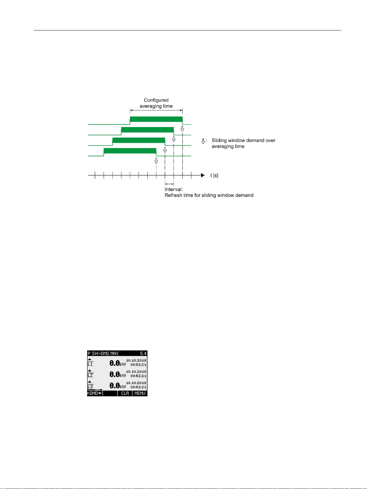
2.3.1 Sliding window demands
The sliding window demand value is the arithmetic mean of all measured values that occur
within a configurable averaging time. "Sliding" means that the interval for the demand
calculation is continuously shifted as a function of time.
Figure 2-1 Sliding window demand
SENTRON PAC4200 supplies sliding window demand values for a large number of
measured variables:
● Per phase or as a total value over all phases
● With the maximum and minimum values, and the time stamp of the extreme value
The sliding window demand values are represented on the display and can be called via the
communication interfaces.
The averaging time can be parameterized on the display or via the communication interface.
The following can be set: 3, 5, 10, 30, 60, 300, 600, 900 seconds.
Representation on the display
A stroke (bar) above the phase designation (L1, L2, L3 or a, b, c) indicates that the displayed
value is a sliding window demand value.
Figure 2-2 Maximum sliding window demand of the active power
PAC4200
System Manual, 05/2019, A5E02316180B-05
21

Description
2.3 Measured variables
2.3.2 Averaging measured values (aggregation)
Based on selected recordings of measured values over time, the user can optimize the
system in accordance with requirements, e.g. with respect to energy consumption.
For this purpose, instantaneous measured values would need to be read out via the
communication interface and stored. Uninterrupted recording requires a high bandwidth, high
availability of communication and high storage capacity. The SENTRON PAC4200 provides
two internal average value generators which can be parameterized independently of each
other. The time averages formed in the device are generated continuously based on all the
associated instantaneous values.
This aggregation of measured values reduces the data volume and consequently the danger
of losing information due to limited communication availability and bandwidth.
The values are updated at time-synchronized, parameterizable intervals:
● A default period length of 10 seconds is set for the measured values of average 1 (file 1).
● A default period length of 15 seconds is set for the measured values of average 2 (file 2).
● Harmonic average (file 3)
The aggregation intervals can be set to anything between 3 seconds and 31536000 seconds
(1 year).
The function is only available via the communication protocols Modbus TCP and Modbus
RTU.
The list of available measured values can be found in the appendix Readout of averages
(aggregation) with function codes 0x03, 0x04 and 0x14 (Page 175).
2.3.3 Other properties of measured variable representation
Zero point suppression level
The zero point suppression level can be set via the interface in 1% steps in the range from
0% to 10% of the primary rated current of the external current transformer (default value
0.0%). Currents within this range are indicated on the display with "0" (zero).
PAC4200
22 System Manual, 05/2019, A5E02316180B-05

Description
Note
Data access via the software
Current and hi
interfaces. For more information, please see the related documentation.
2.4 Load profile
2.4 Load profile
The load profile records the time history of the electric power and thus documents the
distribution of power fluctuations and peaks.
SENTRON PAC4200 supports load profile recording according to the "fixed block" or "rolling
block" method. With both methods, the load profile is stored in the device and made
available at the communication interfaces.
SENTRON PAC4200 interprets synchronization signals which occur at irregular intervals.
Any deviations from the set times are documented in the load profile.
storical load profile data can only be accessed via the communication
Configuring load profile recording
You can adapt load profile recording using the configuration software or on the display of the
device. The following parameters influence the recording:
● Length of the demand period or subperiod
● Number of subperiods per demand period. This number defines the method for recording
the load profile ("fixed block" or "rolling block")
● Type of synchronization
You can also set the following parameter with the configuration software:
● Type of reactive power Q
, Q1, or Qn
tot
PAC4200
System Manual, 05/2019, A5E02316180B-05
23

Description
2.4 Load profile
The Q1 and Q
options that can be set using powerconfig correspond to the reactive power
tot
values shown in the power tetrahedron:
Q
= Displacement reactive power over fundamental U1
1
Q
= Total reactive power
tot
Q
cannot be displayed graphically here and can be explained as follows:
n
Q
= Displacement reactive power over fundamental U1 + harmonic components Uv.
n
As the fundamental component of the voltage is usually high in practice, the following
applies: Q
≈ Q1
n
Figure 2-3 Power tetrahedron
Q1 should generally be used as the preferred setting, as reactive-power compensation
systems primarily refer to cos φ, which is directly related to this.
Mathematical relations
Figure 2-4 Mathematical relations
You can find more information about parameterization on the device display in the chapter
Power demand (Page 95).
Changing the configuration during operation: Changing the period length or the number of
subperiods has a direct impact on load profile recording. The device stops the current
recording and clears all data in the load profile memory. Changing the configuration has no
effect on the device counter. The device is not reset.
PAC4200
24 System Manual, 05/2019, A5E02316180B-05
Description
2.4 Load profile
Load profile recording methods
SENTRON PAC4200 supports the following load profile recording methods:
● Fixed block
● Rolling block
The default setting is the fixed block method with a demand period length of 15 minutes.
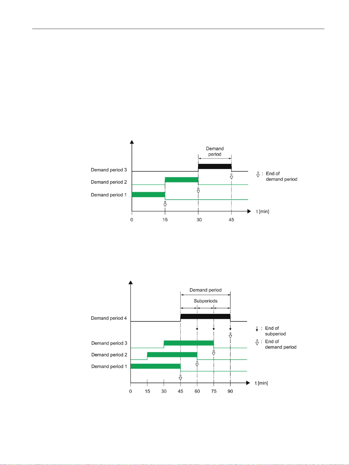
Fixed block method
The load profile data is calculated and stored at the end of each demand period.
Figure 2-5 Load profile, fixed block method
Rolling block method
The rolling block method divides the demand period into subperiods. The load profile data is
calculated and stored at the end of each demand period or subperiod.
Figure 2-6 Load profile, rolling block method
PAC4200
System Manual, 05/2019, A5E02316180B-05
25

Description
Length
demand_period
= n • length
subperiod
; n = number of subperiods
Energy = (cumulated power)
2.4 Load profile
Parameterizing the fixed block and rolling block methods
SENTRON PAC4200 supports the fixed block method as a special case of the rolling block
method. The most important distinguishing feature is the number of subperiods.
Number of subperiods:
The demand period can be divided into a maximum of five subperiods.
● The number "1" defines the fixed block method. In this case, the length of the subperiod
is identical to the length of the demand period.
● The numbers "2" to "5" define the rolling block method.
Length of the subperiods:
The length of a subperiod is an integer part of a full hour. The device allows the following
lengths in minutes:
1, 2, 3, 4, 5, 6, 10, 12, 15, 20, 30, 60 min
Length of demand period:
The length of the demand period cannot be directly configured. It is defined as the product of
the length of a subperiod and the number of subperiods.
Calculation of the power demand and the cumulated power
Arithmetic power demand:
Arithmetic calculation of the power demand referred to the actual length of the demand
period. The arithmetic power demand in the instantaneous period remains constant providing
the power is constant.
Cumulated power:
Cumulative calculation of the power referred to the configured length of the subperiod. The
cumulated power in the instantaneous period increases linearly providing the power is
constant.
The energy can be calculated from the cumulated power as follows:
• (configured period length)
PAC4200
26 System Manual, 05/2019, A5E02316180B-05

Description
Measured variable
Cumulated power
Power
demand
Minimum instantaneous value
Maximum instantaneous value
Active power import
X
X
Reactive power import
X
X
Apparent power
X X X
X
The total power factor import and the total power factor export can be read out
variables indicated in the table.
2.4 Load profile
2.4.1 Historical load profile
Measured variables recorded
SENTRON PAC4200 records the following measured variables:
Table 2- 2 Historical load profile
±X ±X
Active power export X X
±X ±X
Reactive power export X X
via the interface in addition to the measured
The values are recorded per demand period or subperiod:
● Fixed block method
All values are recorded per demand period.
● Rolling block method
Arithmetic power demand values are recorded per demand period.
Cumulated power demand values and maximum / minimum values are recorded per
subperiod.
Accessing the load profile memory
● The complete load profile memory can be read out.
● A definable number of periods can be read out starting at a definable period number.
● The complete load profile memory can be cleared.
Storage concept of the load profile memory
The memory of SENTRON PAC4200 is designed as a circular buffer. If the maximum
available memory is exceeded, the data which has been stored the longest is overwritten by
the newest data.
PAC4200
System Manual, 05/2019, A5E02316180B-05
27

Description
2.4 Load profile
Storage capacity of the load profile memory
The data volume that occurs when a load profile is recorded depends on the length of the
period.
SENTRON PAC4200 can record load profile data for the following configuration over a
period of 40 days:
● Fixed block:
Length of demand period: 15 minutes
● Rolling block:
Length of the subperiods: 15 minutes
This corresponds to a maximum of 3840 recorded periods.
This calculation applies to the ideal case in which the actual period length is identical to the
configured length for all periods over the complete load profile recording time. Any deviations
between the actual and configured period lengths additionally increase the data volume.
2.4.2 Current load profile data at the communication interfaces
Current load profile data
SENTRON PAC4200 supplies the load profile data for the current and instantaneous periods
at the communication interfaces.
● The actual period is the last completed period.
● The instantaneous period is the period still in progress and has not yet been completed.
You can find more information on accessing the data via Modbus in the Appendix.
See also
Measured variables for the load profile with the function codes 0x03 and 0x04 (Page 156)
PAC4200
28 System Manual, 05/2019, A5E02316180B-05

Description
2.4 Load profile
2.4.3 Synchronization of the load profile
The device expects the synchronization pulse at the start of the period.
The synchronization can be initiated by several means:
● By a synchronization pulse at the digital input
● By a synchronization command via the communication interface
● By the internal clock of the device
Handling of irregular, external synchronization pulses
SENTRON PAC4200 checks whether the external synchronization pulse is received at the
set time, too soon, too late, or not at all. If the deviation from the set time exceeds a defined
tolerance, this results in a shorter period.
If the complete time frame for received pulses is offset, SENTRON PAC4200 automatically
adapts to the new time frame.
Synchronization via the communication interface
The synchronization frame contains the length of the subperiod in minutes. The
synchronization command is ignored if the period length sent to the device with the
synchronization frame is different to the length parameterized in the device.
Synchronization via the internal clock
The length of the subperiod, and thus also the demand period, is determined solely by the
internal clock.
A subperiod starts on the full hour plus a multiple of the configured subperiod length.
Correction of the time during the current demand period or beyond the end of the demand
period results in shorter demand periods. SENTRON PAC4200 marks these periods with the
valuation indicator "resynchronized".
It does not record any substitute values for the gaps that are created in the time history.
Response to powering up
All load profiles that have already been recorded remain unchanged.
SENTRON PAC4200 resets the internal clock if it detects load profiles with a date in the
future or a time in the past on powering up.
Impact of a tariff change on the load profile
Tariff changes between off-peak and on-peak have an impact on the load profile because all
values stored in the profile are uniquely assigned to the applicable tariff.
The last tariff remains valid until the end of the instantaneous period. The new tariff takes
effect at the start of the next period. The energy counters of SENTRON PAC4200 are
switched to the other tariff at the end of the instantaneous demand period.
PAC4200
System Manual, 05/2019, A5E02316180B-05
29
 Loading...