

Siemens SENTRON PAC3200 User Manual

SENTRON
Power Monitoring Device
SENTRON PAC3200
Manual
Introduction
Safety instructions
Description
Operation planning
Installation
Connection
Startup
1
2
3
4
5
6
7
Operator control
Parameterize
Maintenance and servicing
Technical data
Dimension drawings
Appendix
ESD Guidelines
8
9
10
11
12
A
B
02/2008
A5E01168664B-04
List of abbreviations
C
Safety Guidelines
This manual contains notices you have to observe in order to ensure your personal safety, as well as to prevent
damage to property. The notices referring to your personal safety are highlighted in the manual by a safety alert
symbol, notices referring only to property damage have no safety alert symbol. These notices shown below are
graded according to the degree of danger.
DANGER
indicates that death or severe personal injury will result if proper precautions are not taken.
WARNING
indicates that death or severe personal injury may result if proper precautions are not taken.
CAUTION
with a safety alert symbol, indicates that minor personal injury can result if proper precautions are not taken.
CAUTION
without a safety alert symbol, indicates that property damage can result if proper precautions are not taken.
NOTICE
indicates that an unintended result or situation can occur if the corresponding information is not taken into
account.
If more than one degree of danger is present, the warning notice representing the highest degree of danger will
be used. A notice warning of injury to persons with a safety alert symbol may also include a warning relating to
property damage.
Qualified Personnel
The device/system may only be set up and used in conjunction with this documentation. Commissioning and
operation of a device/system may only be performed by qualified personnel. Within the context of the safety notes
in this documentation qualified persons are defined as persons who are authorized to commission, ground and
label devices, systems and circuits in accordance with established safety practices and standards.
Prescribed Usage
Note the following:
WARNING
This device may only be used for the applications described in the catalog or the technical description and only
in connection with devices or components from other manufacturers which have been approved or
recommended by Siemens. Correct, reliable operation of the product requires proper transport, storage,
positioning and assembly as well as careful operation and maintenance.
Trademarks
All names identified by ® are registered trademarks of the Siemens AG. The remaining trademarks in this
publication may be trademarks whose use by third parties for their own purposes could violate the rights of the
owner.
Disclaimer of Liability
We have reviewed the contents of this publication to ensure consistency with the hardware and software
described. Since variance cannot be precluded entirely, we cannot guarantee full consistency. However, the
information in this publication is reviewed regularly and any necessary corrections are included in subsequent
editions.
Siemens AG
Automation and Drives
Postfach 48 48
90327 NÜRNBERG
GERMANY
Ordernumber: A5E01168664B-04
Ⓟ 02/2008
Copyright © Siemens AG 2008.
Technical data subject to change

Table of contents
1 Introduction.............................................................................................................................................. 11
1.1 Purpose of this document ............................................................................................................11
1.2 Orientation aids............................................................................................................................12
1.3 Components of the produc
1.4 Contents of the CD for the SENTRON PAC Power Monitoring Dev
1.5 Technical support
1.6 Further documentation
2 Safety instructions ................................................................................................................................... 17
2.1 Safety notes .................................................................................................................................17
3 Description............................................................................................................................................... 19
3.1 Features.......................................................................................................................................19
3.2 Measuring inputs..........................................................................................................................22
3.3 Measured variables......................................................................................................................24
3.4 Power demands and counters
3.5 Tariffs ...........................................................................................................................................33
3.6 Limits............................................................................................................................................34
3.7 Behavior in the case of power failure and power restore
3.8 Digital inputs
3.9 Ethernet port ................................................................................................................................38
3.9.1 Ethernet........................................................................................................................................38
3.9.2 Modbus TCP ................................................................................................................................38
3.9.3 Modbus measured variables with the fu
3.9.4 Structure - Digital input status and di
0x04 .............................................................................................................................................44
3.9.5 Structure - Device diagnostics and dev
3.9.6 Structure - Limit values with func
3.9.7 Modbus status parameters
3.9.8 Modbus settings with the function codes 0x03, 0x04
3.9.9 MODBUS communication parameter with the function
3.9.10 Modbus device information with the fun
3.9.11 Modbus command param
3.9.12 MODBUS standard device identificatio
.........................................................................................................................13
and outputs.............................................................................................................36
t..........................................................................................................12
ice.......................................13
.................................................................................................................15
.....................................................................................................32
............................................................36
nction codes 0x03 and 0x04 .........................................40
gital output status with the function codes 0x03 and
ice status with the function codes 0x03 and 0x04 .........45
tion codes 0x03 and 0x04........................................................45
with the function code 0x02 .............................................................46
and 0x10 ..................................................47
codes 0x03, 0x04 and 0x10..................58
ction codes 0x03, 0x04 and 0x10 .................................59
eters ....................................................................................................61
n with the function code 0x2B ........................................62
3.10 Slot for expansion modul
3.11 Slots on the rear of the device .....................................................................................................64
4 Operation pla
4.1 Operation planning
SENTRON PAC3200
Manual, 02/2008, A5E01168664B-04
nning .................................................................................................................................. 65
es..........................................................................................................63
.......................................................................................................................65
3

Table of contents
5 Installation ............................................................................................................................................... 67
5.1 Unpacking ................................................................................................................................... 67
5.2 Tools............................................................................................................................................ 68
5.3 Mounting dim
5.4 Installation
5.5 Deinstalling
6 Connection
.............................................................................................................................................. 73
ensions .................................................................................................................. 68
steps ......................................................................................................................... 68
.................................................................................................................................. 72
6.1 Safety notes ................................................................................................................................ 73
6.2 Connections ................................................................................................................................ 75
6.3 Connecting the cables to the terminals....................................................................................... 81
6.4 Connection examples.................................................................................................................. 82
7 Startup..................................................................................................................................................... 91
7.1 Overview ..................................................................................................................................... 91
7.2 Applying the supply voltage ........................................................................................................ 92
7.3 Parameterizing the device........................................................................................................... 93
7.4 LANGUAGE/REGIONAL............................................................................................................. 93
7.4.1 Setting the language
................................................................................................................... 93
7.5 BASIC PARAMETERS................................................................................................................ 95
7.5.1 VOLTAGE INPUTS ..................................................................................................................... 95
7.5.1.1 Set the connection type............................................................................................................... 95
7.5.1.2 Measurement using voltage trans
formers................................................................................... 96
7.5.1.3 Setting the conversion ratio of the voltage transformer .............................................................. 97
7.5.1.4 Setting the voltage input.............................................................................................................. 98
7.5.2 CURRENT INPUT....................................................................................................................... 99
7.5.2.1 Setting the conversion ratio of the current transformer............................................................... 99
7.6 Applying the measuring voltage................................................................................................ 100
7.7 Applying the measuring current
7.8 Check the displayed measured
8 Operator cont
rol..................................................................................................................................... 103
................................................................................................ 101
values ..................................................................................... 102
8.1 Device interface ........................................................................................................................ 103
8.1.1 Displays and operator
8.1.2 Display of the measured v
8.1.3 Display of the "MAIN MENU"
8.1.4 Display of the "SETTINGS" menu
controls ................................................................................................. 103
ariables............................................................................................ 110
.................................................................................................... 113
............................................................................................. 114
8.1.5 Display of the device settings ................................................................................................... 115
8.1.6 Edit mode of the devi
ce settings ............................................................................................... 116
8.2 Operator input steps.................................................................................................................. 117
8.2.1 Operator input steps in the measured variable dis
8.2.2 Operator input steps in the
8.2.3 Operator input steps in the
"MAIN MENU" ............................................................................... 119
"SETTINGS" menu........................................................................ 120
play............................................................. 117
8.2.4 Operator input steps in device settings display......................................................................... 121
8.2.5 Operator input steps in edit mode of the devi
SENTRON PAC3200
ce settings.......................................................... 122
4 Manual, 02/2008, A5E01168664B-04

Table of contents
9 Parameterize ......................................................................................................................................... 127
9.1 Introduction ................................................................................................................................127
9.2 Parameterizing the operat
9.2.1 Groups of s
ettings......................................................................................................................128
or interface .......................................................................................128
9.2.2 Device information .....................................................................................................................131
9.2.3 Language, regional
settings.......................................................................................................132
9.2.4 Basic parameters .......................................................................................................................133
9.2.5 Power demand...........................................................................................................................136
9.2.6 Integrated I/O .............................................................................................................................137
9.2.7 Communication ..........................................................................................................................140
9.2.8 Display .......................................................................................................................................141
9.2.9 Advanced ...................................................................................................................................142
9.2.10 PAC PROFIBUS DP expans
9.2.11 PAC RS485 expansion m
9.2.12 Password managem
ent .............................................................................................................150
ion module....................................................................................149
odule .................................................................................................150
9.2.12.1 Introduction ................................................................................................................................150
9.2.12.2 Calling password management..................................................................................................150
9.2.12.3 Switch on password protection ..................................................................................................151
9.2.12.4 Switch off password protec
tion ..................................................................................................151
9.2.12.5 Change password ......................................................................................................................152
9.2.12.6 Password lost - what to do?
10 Maintenance and se
rvicing .................................................................................................................... 155
.......................................................................................................154
10.1 Cleaning .....................................................................................................................................155
10.2 Repair.........................................................................................................................................156
10.3 Disposal .....................................................................................................................................156
11 Technical
data ....................................................................................................................................... 157
11.1 Technical data............................................................................................................................157
11.2 Labeling......................................................................................................................................165
12 Dimension dr
awings .............................................................................................................................. 167
12.1 Dimension drawings...................................................................................................................167
A Appendix................................................................................................................................................ 171
A.1 Certification
marks .....................................................................................................................171
A.2 Correction sheet.........................................................................................................................172
B ESD Guidelin
es ..................................................................................................................................... 173
B.1 Electrostatic sensitive devices (ESD) ........................................................................................173
C List of abbrev
iations............................................................................................................................... 175
C.1 Abbreviations .............................................................................................................................175
Glossary ................................................................................................................................................ 177
Index...................................................................................................................................................... 179
SENTRON PAC3200
Manual, 02/2008, A5E01168664B-04
5

Table of contents
Tables
Table 1-1
Table 1-2 Online service and support ......................................................................................................... 14
Table 1-3 Technical Support ....................................................................................................................... 14
Table 3-1 Device versions........................................................................................................................... 20
Table 3-2 Available connection types.......................................................................................................... 23
Table 3-3 Measured variables..................................................................................................................... 24
Table 3-4 Display of the measured variables depending on the connection type ...................................... 26
Table 3-5 Available measured variables ..................................................................................................... 28
Table 3-6 Available measured variables ..................................................................................................... 40
Table 3-7 Structure - Status of the digital inputs and status of the digital outputs...................................... 44
Table 3-8 Modbus offset 205, tab 2: Structure device status and device diagnostics................................ 45
Table 3-9 Modbus Offset 203, Register 2: Limit Violations......................................................................... 45
Table 3-10 Status parameters....................................................................................................................... 46
Table 3-11 Settings parameters .................................................................................................................... 47
Table 3-12 Settings parameter for the digital input ....................................................................................... 48
Table 3-13 Settings parameter for the digital output..................................................................................... 48
Table 3-14 Settings parameter for language, phase labels and universal counters source......................... 49
Contacts in your region - worldwide............................................................................................ 14
Table 3-15 Settings parameter for the display .............................................................................................. 49
Table 3-16 Settings parameter for limit value 0 ............................................................................................ 50
Table 3-17 Settings parameter for limit value 1 ............................................................................................ 51
Table 3-18 Settings parameter for limit value 2 ............................................................................................ 52
Table 3-19 Settings parameter for limit value 3 ............................................................................................ 53
Table 3-20 Settings parameter for limit value 4 ............................................................................................ 55
Table 3-21 Settings parameter for limit value 5 ............................................................................................ 56
Table 3-22 Communication parameters........................................................................................................ 58
Table 3-23 I&M 0 parameter of the SENTRON PAC Power Monitoring Device with the function codes
0x03 and 0x04............................................................................................................................. 59
Table 3-24 I&M 1-4 parameters with the function codes 0x03, 0x04 and 0x10............................................ 60
Table 3-25 I&M 0 parameter of the module in slot 1 with the function codes 0x03 and 0x04 ...................... 60
Table 3-26 Command parameters ................................................................................................................ 61
Table 3-27 MODBUS standard device identification parameters ................................................................. 62
Table 7-1 Connection of supply voltage...................................................................................................... 92
Table 7-2 Available connection types.......................................................................................................... 95
Table 8-1 Assignments of the function keys in the "MAIN MENU" ........................................................... 114
SENTRON PAC3200
6 Manual, 02/2008, A5E01168664B-04

Table of contents
Table 8-2 Assignments of the function keys in the "SETTINGS" menu.....................................................115
Table 8-3 Assignments of the function keys in the device settings display ...............................................116
Table 8-4 Assignments of the function keys in edit mode of the device settings.......................................117
Table 11-1 AC/DC multi-range power supply...............................................................................................159
Table 11-2 Extra-low voltage DC power supply:..........................................................................................159
Table A-1 Errors, comments, and suggestions for improvements .............................................................172
Table B-1 Protective measures ..................................................................................................................174
Table C-1 Meaning of abbreviations...........................................................................................................175
Figures
Figure 2-1
Figure 3-1 Overload display ..........................................................................................................................25
Figure 3-2 Display of the measured voltage in the case of connection type 3P4W......................................26
Figure 3-3 Display of the measured voltage in the case of connection type 1P2W......................................26
Figure 3-4 "LIMIT LOGIC" device setting ......................................................................................................34
Figure 3-5 Representation of limit violations .................................................................................................35
Figure 3-6 Energy pulse output .....................................................................................................................36
Figure 3-7 Pulse length and turn-off time......................................................................................................37
Figure 3-8 "COMMUNICATION" device setting ............................................................................................38
Figure 3-9 Enter IP address ..........................................................................................................................39
Figure 3-10 Typical display with entered values .............................................................................................39
Figure 3-11 Switching the protocol to MODBUS TCP.....................................................................................39
Figure 3-12 Restart prompt .............................................................................................................................39
Figure 3-13 SENTRON PAC3200 with screw terminals, rear .........................................................................63
Figure 3-14 Not available for use! Slot for memory card and battery compartment .......................................64
Figure 4-1 Mounting position.........................................................................................................................65
Figure 5-1 Installation step E - Strain relief for RJ45 connector ...................................................................71
Safety-related symbols on the device..........................................................................................18
Figure 5-2 Deinstallation, releasing the locking hooks..................................................................................72
Figure 6-1 Connection designations, view of the rear and top of the device with screw terminals...............75
Figure 6-2 Connection designations, view of the rear and top of the device with ring lug terminals ............76
Figure 6-3 Terminal labeling with screw terminals ........................................................................................77
Figure 6-4 Labeling of the ring lug terminals.................................................................................................78
Figure 6-5 Terminal block: digital input and output, reference potential .......................................................79
Figure 6-6 Connecting cables to the screw terminal .....................................................................................81
Figure 6-7 Connecting the cables to the ring lug terminals:..........................................................................82
SENTRON PAC3200
Manual, 02/2008, A5E01168664B-04
7

Table of contents
Figure 6-8 Connection type 3P4W, without voltage transformer, with three current transformers .............. 83
Figure 6-9 Connection type 3P4W, with voltage transformer, with three current transformers ................... 83
Figure 6-10 Connection type 3P4WB, without voltage transformer, with one current transformer................ 84
Figure 6-11 Connection type 3P4WB, with voltage transformer, with one current transformer..................... 84
Figure 6-12 Connection type 3P3W, without voltage transformer, with three current transformers .............. 85
Figure 6-13 Connection type 3P3W, with voltage transformer, with three current transformers ................... 85
Figure 6-14 Connection type 3P3W, without voltage transformer, with two current transformers................. 86
Figure 6-15 Connection type 3P3W, with voltage transformer, with two current transformers...................... 86
Figure 6-16 Connection type 3P3WB, without voltage transformer, with one current transformer................ 87
Figure 6-17 Connection type 3P3WB, with voltage transformer, with one current transformer..................... 87
Figure 6-18 Connection type 3P4W, without voltage transformer, with two current transformers................. 88
Figure 6-19 Connection type 1P2W, without voltage transformer, with one current transformer .................. 88
Figure 6-20 Connection type 3P3W, with voltage transformer, with three current transformers ................... 89
Figure 7-1 Language selection..................................................................................................................... 93
Figure 7-2 "SETTINGS" menu...................................................................................................................... 94
Figure 7-3 "LANGUAGE" edit mode............................................................................................................. 94
Figure 7-4 "CONNECTION TYPE" device setting........................................................................................ 96
Figure 7-5 Device setting "USE PTs?" ......................................................................................................... 96
Figure 7-6 Device setting "USE PTs?" ......................................................................................................... 97
Figure 7-7 "VOLTAGE INPUTS" device setting ........................................................................................... 98
Figure 7-8 "VOLTAGE INPUTS" device setting ........................................................................................... 98
Figure 7-9 "CURRENT INPUTS" device setting........................................................................................... 99
Figure 7-10 Device setting "CURRENT INPUTS - CT PRIMARY?"............................................................. 100
Figure 8-1 Device interface ........................................................................................................................ 103
Figure 8-2 Information structure and navigation......................................................................................... 106
Figure 8-3 Scroll bar of the menu list.......................................................................................................... 107
Figure 8-4 Start of the list/end of the list..................................................................................................... 108
Figure 8-5 Scroll bar ................................................................................................................................... 108
Figure 8-6 Maximum/minimum symbols..................................................................................................... 109
Figure 8-7 Display of the measured variables............................................................................................ 110
Figure 8-8 Display of main menu................................................................................................................ 113
Figure 8-9 Display of the "SETTINGS" menu............................................................................................. 114
Figure 8-10 Display of the device settings ................................................................................................... 115
Figure 8-11 Edit mode of the device settings ............................................................................................... 116
Figure 8-12 Display the instantaneous, maximum/minimum or average value............................................ 118
Figure 8-13 Reset the maximum or minimum value to the instantaneous value ......................................... 118
SENTRON PAC3200
8 Manual, 02/2008, A5E01168664B-04

Table of contents
Figure 8-14 Calling the "MAIN MENU"..........................................................................................................119
Figure 8-15 Cancel menu selection...............................................................................................................120
Figure 8-16 Displaying a setting....................................................................................................................121
Figure 8-17 Calling edit mode .......................................................................................................................121
Figure 8-18 Exiting the display ......................................................................................................................121
Figure 8-19 Enter password ..........................................................................................................................122
Figure 8-20 Switching a device setting ON/OFF...........................................................................................122
Figure 8-21 Device setting, switching between several alternatives.............................................................122
Figure 8-22 Selecting from several settings..................................................................................................123
Figure 8-23 Defining multi-digit values ..........................................................................................................123
Figure 8-24 Exiting edit mode .......................................................................................................................123
Figure 9-1 "Settings" menu..........................................................................................................................128
Figure 9-2 "INFORMATION" device setting ................................................................................................131
Figure 9-3 "LANGUAGE SETTING" device setting.....................................................................................132
Figure 9-4 "BASIC PARAMETERS" device setting.....................................................................................133
Figure 9-5 "VOLTAGE INPUTS" device setting ..........................................................................................133
Figure 9-6 "CURRENT INPUTS" device setting..........................................................................................135
Figure 9-7 "POWER DEMAND" device setting ...........................................................................................136
Figure 9-8 "INTEGRATED I/O" device setting ............................................................................................137
Figure 9-9 "DIGITAL OUTPUT" device setting............................................................................................137
Figure 9-10 "DIGITAL OUTPUT" device setting............................................................................................138
Figure 9-11 "DIGITAL INPUT" device setting................................................................................................139
Figure 9-12 "DIGITAL INPUT" device setting................................................................................................139
Figure 9-13 "COMMUNICATION" device setting ..........................................................................................140
Figure 9-14 "DISPLAY" device setting ..........................................................................................................141
Figure 9-15 "INVERT DISPLAY" device setting switched on........................................................................142
Figure 9-16 "DISPLAY TEST" device setting ................................................................................................142
Figure 9-17 "ADVANCED" device setting .....................................................................................................142
Figure 9-18 "PASSWORD PROTECTION" device setting............................................................................143
Figure 9-19 "LIMITS" device setting..............................................................................................................143
Figure 9-20 "LIMIT 0" device setting .............................................................................................................144
Figure 9-21 Effect of delay and hysteresis on upper and lower limit violations ............................................146
Figure 9-22 "LIMIT LOGIC" device settings ..................................................................................................147
Figure 9-23 "RESET" device setting .............................................................................................................148
Figure 9-24 "PASSWORD PROTECTION" device setting............................................................................151
Figure 9-25 Switch off password protection ..................................................................................................152
SENTRON PAC3200
Manual, 02/2008, A5E01168664B-04
9

Table of contents
Figure 9-26 Change password ..................................................................................................................... 153
Figure 9-27 Change password - Password protection on ............................................................................ 154
Figure 11-1 Device labeling.......................................................................................................................... 165
Figure 12-1 Panel cutout .............................................................................................................................. 167
Figure 12-2 Frame dimensions with optional PAC PROFIBUS DP expansion module connected ............. 168
Figure 12-3 Frame dimensions with optional PAC PROFIBUS DP expansion module connected ............. 168
Figure 12-4 Side-by-side installation ............................................................................................................ 169
Figure 12-5 Clearances, device with screw terminal (on the left), device with ring lug terminal (on the
right) .......................................................................................................................................... 170
Figure B-1 ESD work center ....................................................................................................................... 174
SENTRON PAC3200
10 Manual, 02/2008, A5E01168664B-04

Introduction
1.1 Purpose of this document
This present manual describes the SENTRON PAC3200 Power Monitoring Device.
It is intended for the use of:
● Planners
● Plant operators
● Commissioning engineers
● Service and maintenance personnel
Required basic knowledge
A general knowledge of the field of electrical engineering is required to understand this
manual.
Knowledge of the relevant safety regulations and standards is required for installing and
connecting the device.
1
Validity range
This manual applies to the following delivery versions of the device:
SENTRON PAC3200 for panel mounting with
● LC display
● Screw terminal
● Ring lug terminal
Those device properties valid at the time of publication of the manual are described.
SENTRON PAC3200
Manual, 02/2008, A5E01168664B-04
11

Introduction
1.2 Orientation aids
1.2 Orientation aids
General information
The manual includes the following orientation aids:
● Table of contents
● List of figures and tables
● List of abbreviations
● Glossary
● Index
1.3 Components of the product
Description
The package includes:
● 1 SENTRON PAC3200 Power Monitoring Device
● 2 brackets for panel mounting
● 1 SENTRON PAC3200 operating instructions
● 1 CD-ROM
SENTRON PAC3200
12 Manual, 02/2008, A5E01168664B-04

Introduction
1.4 Contents of the CD for the SENTRON PAC Power Monitoring Device
1.4 Contents of the CD for the SENTRON PAC Power Monitoring Device
CD contents
The SENTRON PAC CD includes the following files:
● The manual for the SENTRON PAC Power Monitoring Device in all available languages
● The operating instructions for the SENTRON PAC Power Monitoring Device in all
available languages
● The manual for the PAC PROFIBUS DP expansion module in all available languages
● The operating instructions for the PAC PROFIBUS DP expansion module in all available
languages
● The GSD files for the PAC PROFIBUS DP expansion module and the SENTRON PAC
Power Monitoring Device.
Note
Specific GSD file
This GSD file is only designed for the use of the PAC PROFIBUS DP expansion module
with a specific type of the SENTRON PAC Power Monitoring Device.
● The manual for the PAC RS485 expansion module in all available languages
● The operating instructions for the PAC RS485 expansion module in all available
languages
● The SENTRON powerconfig software including online help in all available languages.
● The language packages for the SENTRON PAC Power Monitoring Device
This CD is supplied with the SENTRON PAC Power Monitoring Device.
1.5 Technical support
Contact for technical problems and other questions
Help is available from:
● Service and support contacts in your region - worldwide
● Online service and support
● Technical support
SENTRON PAC3200
Manual, 02/2008, A5E01168664B-04
13

Introduction
1.5 Technical support
Contacts in the region
Contacts in your region can provide support worldwide.
Table 1-1 Contacts in your region - worldwide
Utility Address, number
Internet: Service and support (http://www.siemens.com/automation/service&support) under
"Contact us > Contacts"
Support address:
SIEMENS AG
A&D CD MM1
Gleiwitzerstr. 555
D-90475 Nuremberg
Online support
Technical Support
This comprehensive information system is available day and night via the Internet. Online
service and support offers product support, services and support, and support tools from the
shop.
Table 1-2 Online service and support
Utility Address, number
Internet: Online service and support (http://www.siemens.com/automation/service&support)
Technical support offers:
● Expert advice on technical queries over a broad subject area
● Tailored services relating to our products and systems
If you require technical support or you have questions about the product, contact Technical
Support.
Table 1-3 Technical Support
Utility Address, number
Phone: +49 (0)180-50-50-222
Fax: +49 (0)180-50-50-223
Internet: Support request (http://www.siemens.com/automation/support-request)
SENTRON PAC3200
14 Manual, 02/2008, A5E01168664B-04

Introduction
1.6 Further documentation
1.6 Further documentation
Overview
You can find further details in the following manuals:
● SIMATIC NET "PROFIBUS network manual"
● "SENTRON PAC3200" operating instructions
● "PAC PROFIBUS DP Expansion Module" manual
● "PAC PROFIBUS DP Expansion Module" operating instructions
● "PAC RS485 expansion module" manual
● "PAC RS485 expansion module" operating instructions
SENTRON PAC3200
Manual, 02/2008, A5E01168664B-04
15

Introduction
1.6 Further documentation
SENTRON PAC3200
16 Manual, 02/2008, A5E01168664B-04

Safety instructions
2.1 Safety notes
General safety notes
DANGER
Danger! High voltage
Will cause death or serious injury.
Turn off and lock out all power supplying this device before working on this device.
2
SENTRON PAC3200
Manual, 02/2008, A5E01168664B-04
17
Safety instructions
2.1 Safety notes
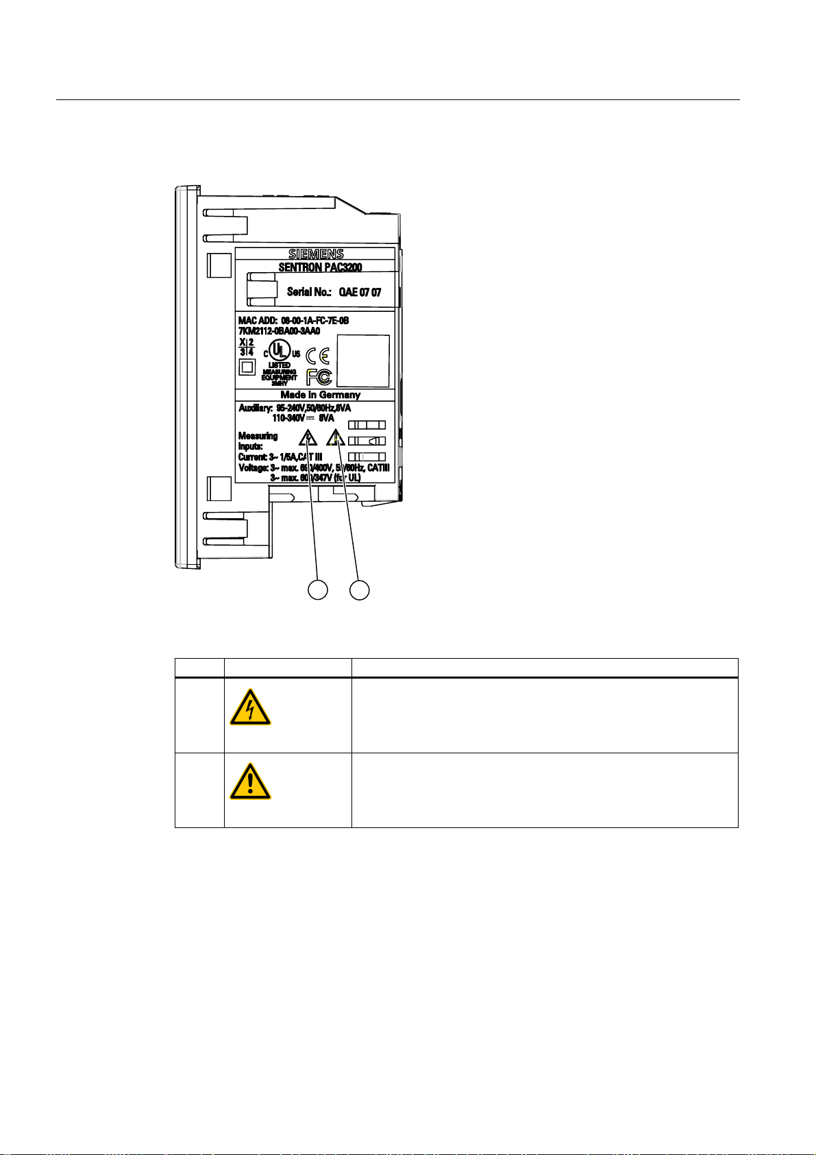
Safety-related symbols on the device
See also
Figure 2-1 Safety-related symbols on the device
Symbol Meaning
(1)
Danger of electric shock.
(2)
Caution! General hazard area.
Applying the measuring current (Page 101)
Applying the measuring voltage (Page 100)
Applying the supply voltage (Page 92)
SENTRON PAC3200
18 Manual, 02/2008, A5E01168664B-04

Description
3.1 Features
The SENTRON PAC3200 is a Power Monitoring Device for displaying all the relevant system
parameters in low-voltage power distribution. It is capable of single-phase, two-phase or
three-phase measurement and can be used in two-wire, three-wire, four-wire, TN, TT and IT
systems.
Thanks to its compact design in 96 x 96 mm format, it is an ideal replacement for all
conventional analog indicating instruments.
Thanks to its large measured voltage range, the SENTRON PAC3200 with multi-range
power supply can be connected direct in any low-voltage system up to a rated system
voltage of 690 V (max. 600 V for UL).
For the device version with extra-low voltage power supply, direct connection to systems up
to 500 V is permissible.
Higher voltages can be measured using voltage transformers. For measuring current, either
x/1 A or x/5 A current transformer can be used.
The large graphical LC display permits reading even from a distance. The
SENTRON PAC3200 has backlighting that can be adjusted in steps for optimal readability
even under poor lighting conditions.
3
The combination of four function keys with the multi-language plaintext displays makes
intuitive user prompting possible. The experienced operator can also use direct navigation
for quicker selection of the desired display menu.
The SENTRON PAC3200 has a range of useful monitoring, diagnostics and service
functions, a two-tariff active energy and reactive energy counter, a universal counter, and a
working hours counter for monitoring the running time of connected loads.
The integral Ethernet interface or an optionally available interface module can be used for
communication.
In addition, the SENTRON PAC3200 has a multifunctional digital input and digital output.
The parameters can be set either direct on the device or via the communications interface.
Password protection is integrated via the front of the device to guard against unauthorized
access.
SENTRON PAC3200
Manual, 02/2008, A5E01168664B-04
19

Description
3.1 Features
Device versions
The device is available in the following versions:
Table 3-1 Device versions
SENTRON PAC3200 Power Monitoring Device
Order No. Description
7KM2112-0BA00-2AA0 SENTRON PAC3200 with multi-range power supply with ring lug terminals
7KM2112-0BA00-3AA0 SENTRON PAC3200 with multi-range power supply with screw terminals
7KM2111-1BA00-3AA0 SENTRON PAC3200 with extra-low voltage power supply with screw terminals
Measurement
● Derivation of more than 50 measured variables from the basic measured variables with
maximum and minimum values (slave pointer function), as well as mean values for
phase-to-neutral voltages, phase-to-phase voltages and currents. The minimum and
maximum values are indicated in addition to the mean values.
● With the multi-range power supply, the SENTRON PAC3200 can be connected direct to
690 V (max. 600 V for UL) industrial systems (measuring category III, pollution degree 2).
Higher voltages using voltage transformers.
● With the extra-low voltage power supply, the SENTRON PAC3200 can be connected
direct to systems up to 500 V.
● For current transformers x/1 A and x/5 A. Conversion ratio and current direction
programmable.
● Can be used in 2-, 3- and 4-wire systems. Suitable for TN, TT and IT systems.
● High measuring accuracy: 0.5% of the measured value for energy.
Counters and power demand
● A total of 10 energy counters capture active energy, reactive energy, apparent energy for
off-peak and on-peak, import and export.
● Calculation and storage of the last demand period mean value for active power and
reactive power for simple generation of load profiles using software. Programmable
demand period from 1 to 60 mins.
● Configurable universal counter for counting limit violations and status changes at the
digital input or output, or for indicating the active power or reactive power of a connected
pulse encoder, e.g. S0 interface.
● Working hours counter for monitoring the runtime of a connected load.
SENTRON PAC3200
20 Manual, 02/2008, A5E01168664B-04

Description
3.1 Features
Monitoring functions
● Monitoring of 6 limit values. The limit values can be combined according to logic
AND/OR. A group message that indicates the violation of at least one limit value can be
generated using an OR operation.
● Phase sequence monitor.
● Status monitoring of the digital input.
● Monitoring the operating status of the SENTRON PAC3200.
Displays and controls
● Large backlit graphics LC display for optimal readability even from a distance.
● Menu-driven parameterization and operation with plaintext display.
● Choice of output language for menu and text displays.
● Phase labels selectable (L1, L2, L3 <=> a, b, c).
Power supply
Installation format
Interface
● AC/DC multi-range power supply:
Supply by 95 to 240 V AC ±10 % / 50 / 60 Hz or
110 to 340 V DC ±10 %.
● Extra-low voltage DC power supply:
Supply by 24 V, 48 V and 60 V DC ±10 % or
22 to 65 V DC ±10 %.
● Panel-mounting format 96 x 96 mm.
● Only 51-mm installation depth without expansion module, 73-mm installation depth with
expansion module. The interface connector is plugged into the expansion module on the
side and thus does not increase the installation depth.
● Integrated Ethernet interface.
● Expandable with optional expansion module (e.g. PAC PROFIBUS DP Expansion
Module).
● Expandable with optional expansion module (e.g. PAC RS485 Expansion Module).
SENTRON PAC3200
Manual, 02/2008, A5E01168664B-04
21
Description
3.2 Measuring inputs
Input and output
● Multifunctional digital input for tariff changing, demand period synchronization, status
monitoring or acquisition of energy pulses from third-party devices.
● Multifunctional digital output, programmable as energy pulse output for active energy or
reactive energy pulses, for showing the direction of rotation, indicating the working hours
of the SENTRON PAC3200, outputting limit violations, or as a switching output for remote
control via PC.
Protection
Password protection on the device by means of 4-character code.
See also
Measured variables (Page 24)
Connection (Page 73)
Technical data (Page 157)
3.2 Measuring inputs
Current measurement
Voltage measurement
CAUTION
AC current measurement only
The device is not suitable for measuring DC current.
SENTRON PAC3200 is designed for:
● Measuring current of 1 A or 5 A for connecting standard current transformers. Each
current measuring input can take a continuous load of 10 A (max. 300 V). Surge
withstand capability is possible for currents up to 100 A and a duration of 1 s.
CAUTION
AC voltage measurement only
The device is not suitable for measuring DC voltage.
SENTRON PAC3200
22 Manual, 02/2008, A5E01168664B-04
Description
3.2 Measuring inputs
SENTRON PAC3200 is designed for:
● Direct measurement on the system or using voltage transformers. The measuring voltage
inputs of the device measure direct via protective impedances. External voltage
transformers are required to measure higher voltages than the permissible rated input
voltages.
● Measuring voltage to 400 V / 690 V (max. 347 V / 600 V for UL) with multi-range power
supply. The device is designed for measuring input voltages up to 400 V to the neutral
conductor and 690 V to the external conductor.
● Measuring voltage to 289 V / 500 V with extra-low voltage power supply. The device is
designed for measuring input voltages up to 289 V to the neutral conductor and 500 V to
the external conductor.
Connection types
Five connection types have been provided for connecting two-wire, three-wire or four-wire
systems with balanced or unbalanced load.
Table 3-2 Available connection types
See also
Short code Connection type
3P4W 3 phases, 4 conductors, unbalanced load
3P3W 3 phases, 3 conductors, unbalanced load
3P4WB 3 phases, 4 conductors, balanced load
3P3WB 3 phases, 3 conductors, balanced load
1P2W Single-phase AC
The input circuit of the device must correspond to one of the connection types listed. Select
the suitable connection type for the purpose.
You can find connection examples in the chapter "Connecting".
CAUTION
Local power supply conditions
Before connecting the SENTRON PAC3200, you must ensure that the local power supply
conditions agree with the specifications on the type plate.
The short code of the connection type must be entered in the device settings at startup. You
can find the instructions for parameterizing the connection type in the chapter "Starting up".
Connection (Page 73)
Set the connection type (Page 95)
Applying the measuring voltage (Page 100)
Applying the measuring current (Page 101)
SENTRON PAC3200
Manual, 02/2008, A5E01168664B-04
23

Description
3.3 Measured variables
3.3 Measured variables
Overview
The table below lists all measured variables that the device records or derives from basic
variables.
Table 3-3 Measured variables
Root-mean-square
values
Designation Instantane
ous value
Min. Max. Mean
value
over all
Mean value
over demand
period
Total value Unit
phases
Phase-to-neutral
voltage
Phase-to-phase
voltage
Current Ia / Ib / Ic ✓ ✓ ✓ ✓
Apparent power per
phase
Active power per
phase import/export
Reactive power per
phase
positive/negative
Total apparent
power
Total active power
import/export
Total reactive
power
V
/ V
/ V
b-n
b-c
/
/
a-n
V
c-n
V
a-b
V
c-a
VAa / VAb /
VAc
±Wa / ±Wb /
±Wc
±VARa /
±VARb /
✓ ✓ ✓ ✓1) [V, kV]
✓ ✓ ✓ ✓1) [V, kV]
1)
[A, kA]
✓ ✓ ✓ [VA, kVA, MVA,
GVA]
✓ ✓ ✓ [W, kW, MW,
GW]
✓ ✓ ✓ [var, kvar, Mvar,
Gvar]
VARc
VA
✓ ✓ ✓ [VA, kVA, MVA,
total
GVA]
±W
✓ ✓ ✓ ✓
total
2)
[W, kW, MW,
GW]
±VAR
✓ ✓ ✓ ✓
total
2)
[var, kvar, Mvar,
Gvar]
positive/negative
Power factor |PFa| / |PFb|
✓ ✓ ✓ [%]
/ |PFc|
Total power factor PF
✓ ✓ ✓ ✓ [%]
total
Line frequency f ✓ ✓ ✓ [Hz]
THD voltage THD-Va /
THD-V
b
/
✓ ✓ [%]
THD-Vc
THD current THD-Ia /
✓ ✓ [%]
THD-Ib /
THD-Ic
Active energy
import3) / export
Reactive energy
positive4) / negative
Apparent energy ±Ws
±W
✓ [Wh, kWh, MWh,
a...c
GWh]
±WVAR
✓ [varh, kvarh,
a..c
Mvarh, Gvarh]
✓ [VAh, kVAh,
L1...3
MVAh, GVAh]
Universal counter
5)
SENTRON PAC3200
24 Manual, 02/2008, A5E01168664B-04

Description
3.3 Measured variables
Root-mean-square
values
Working hours
counter
Voltage unbalance Unbal.V ✓ [%]
Current unbalance Unbal. A ✓ [%]
1) Instantaneous, minimum and maximum value in each case.
2) Mean value of the total power of the system/plant. Can only be called via bus.
3) The current tariff is shown on the display. The "+" sign stands for "Active energy import". The "-" sign stands
for "Active energy export".
4) The current tariff is shown on the display. The "+" sign stands for "Reactive energy import". The "-" sign
stands for "Reactive energy export".
5) The unit depends on the settings: no unit or "kWh" or "kvarh" in the case of pulse counter function.
Designation Instantane
ous value
Bh (load
runtime)
✓ [h]
Min. Max. Mean
value
over all
phases
Mean value
over demand
period
Total value Unit
Overload display
Voltage or current overload is indicated on the display.
Figure 3-1 Overload display
Zero point suppression level
The zero point suppression level can be set via the interface in the range 0% to 10% of the
measuring range final value (default value 0.0%). Currents within this range are indicated on
the display with "0" (zero).
Current direction
The current direction can be changed on the device or via the interface for all phases in
common. This means it is not necessary to change the terminal connections of the current
transformer in the event of connection errors.
SENTRON PAC3200
Manual, 02/2008, A5E01168664B-04
25

Description
3.3 Measured variables
Display of the measured variables depending on the connection type
The total extent of representable measured variables is restricted by the method of
connecting the device.
A measured value that cannot be indicated because of the connection method is shown on
the display by means of a broken line "----".
Figure 3-2 Display of the measured voltage in the case of connection type 3P4W
Figure 3-3 Display of the measured voltage in the case of connection type 1P2W
The table below, "Display of the measured values depending on the connection type", shows
which measured values can be represented depending on the connection type.
Table 3-4 Display of the measured variables depending on the connection type
Connection type
Measured variable
Voltage a-n ✓ ✓ ✓
Voltage b-n ✓
Voltage c-n ✓
Average Voltage
a-n, b-n, c-n
Voltage a-b ✓ ✓ ✓
Voltage b-c ✓ ✓ ✓
Voltage c-a ✓ ✓ ✓
Average Voltage
a-b,b-c ,c-a
Current a ✓ ✓ ✓ ✓ ✓
Current b ✓ ✓
Current c ✓ ✓
Average Current a, b, c ✓ ✓
Apparent Power a ✓ ✓ ✓
Apparent Power b ✓
Apparent Power c ✓
3P4W 3P3W 3P4WB 3P3WB 1P2W
✓
✓ ✓ ✓
SENTRON PAC3200
26 Manual, 02/2008, A5E01168664B-04

Description
3.3 Measured variables
Connection type
Measured variable
Active Power a ✓ ✓ ✓
Active Power b ✓
Active Power c ✓
Reactive Power a ✓ ✓ ✓
Reactive Power b ✓
Reactive Power c ✓
Total Apparent Power ✓ ✓ ✓ ✓ ✓
Total Active Power ✓ ✓ ✓ ✓ ✓
Total Reactive Power ✓ ✓ ✓ ✓ ✓
Power Factor a ✓ ✓ ✓
Power Factor b ✓
Power Factor c ✓
Total Power Factor ✓ ✓ ✓ ✓ ✓
Frequency ✓ ✓ ✓ ✓ ✓
THD Voltage a ✓ ✓ ✓
THD Voltage b ✓
THD Voltage c ✓
THD Current a ✓ ✓ ✓ ✓ ✓
THD Current b ✓ ✓
THD Current c ✓ ✓
Active Energy Import ✓ ✓ ✓ ✓ ✓
Active Energy Export ✓ ✓ ✓ ✓ ✓
Reactive Energy Positive ✓ ✓ ✓ ✓ ✓
Reactive Energy Negative ✓ ✓ ✓ ✓ ✓
Apparent Energy ✓ ✓ ✓ ✓ ✓
Voltage Unbalance ✓
Current Unbalance ✓
Universal Counter ✓ ✓ ✓ ✓ ✓
Working Hours Counter ✓ ✓ ✓ ✓ ✓
3P4W 3P3W 3P4WB 3P3WB 1P2W
See also
Features (Page 19)
Parameterize (Page 127)
Connection examples (Page 82)
SENTRON PAC3200
Manual, 02/2008, A5E01168664B-04
27

Description
3.3 Measured variables
Measured variables of the SENTRON PAC Power Monitoring Device
The measured variables are provided by the SENTRON PAC Power Monitoring Device.
Table 3-5 Available measured variables
Name Abb.
EN + IEC
Voltage V
Voltage V
Voltage V
Voltage V
Voltage V
Voltage V
V
a-n
V
b-n
V
c-n
V
a-b
V
b-c
V
c-a
V
L1-N
V
L2-N
V
L3-N
V
L1-L2
V
L2-L3
V
L3-L1
Current a IL1 I
Current b IL2 I
Current c IL3 I
Apparent Power a VAL1 VA
Apparent Power b VAL2 VA
Apparent Power c VAL3 VA
Active Power a ± WL1 ± W
Active Power b ± WL2 ± W
Active Power c ± WL3 ± W
Reactive Power a ± varL1 ± var
Reactive Power b ± varL2 ± var
Reactive Power c ± varL3 ± var
Abb.
Format Unit Value range Access
EN + NAFTA
Float V - R
a-n
Float V - R
b-n
Float V - R
c-n
Float V - R
a-b
Float V - R
b-c
Float V - R
c-a
Float A - R
a
Float A - R
b
Float A - R
c
Float VA - R
a
Float VA - R
b
Float VA - R
c
Float W - R
a
Float W - R
b
Float W - R
c
Float var - R
a
Float var - R
b
Float var - R
c
Power Factor a |PFL1| |PFa| Float - 0 ... 1 R
Power Factor b |PFL2| |PFb| Float - 0 ... 1 R
Power Factor c |PFL3| |PFc| Float - 0 ... 1 R
THD-R Voltage a THD-VL1 THD-Va Float % 0 ... 100 R
THD-R Voltage b THD-VL2 THD-Vb Float % 0 ... 100 R
THD-R Voltage c THD-VL3 THD-Vc Float % 0 ... 100 R
THD-R Current a THD-IL1 THD-Ia Float % 0 ... 100 R
THD-R Current b THD-IL2 THD-Ib Float % 0 ... 100 R
THD-R Current c THD-IL3 THD-Ic Float % 0 ... 100 R
Frequency f f Float Hz 45 ... 65 R
Average Voltage V
Average Voltage V
Average Current I
U
ph-n
V
ph-ph
L-N MW
L-L AVG
I
AVG
V
V
ph-n AVG
ph-ph AVG
Float A - R
AVG
Float V - R
Float V - R
Total Apparent Power Total VA Total VA Float VA - R
Total Active Power Total W Total W Float W - R
Total Reactive Power Total var Total var Float var - R
Total Power Factor Total PF Total PF Float - R
SENTRON PAC3200
28 Manual, 02/2008, A5E01168664B-04

Description
3.3 Measured variables
Name Abb.
EN + IEC
Abb.
EN + NAFTA
Format Unit Value range Access
Amplitude Unbalance - Voltage Unbal. V Unbal. V Float % 0 ... 100 R
Amplitude Unbalance - Current Unbal.. A Unbal. A Float % 0 ... 200 R
Maximum Voltage V
Maximum Voltage V
Maximum Voltage V
Max. Voltage V
Max. Voltage V
Max. Voltage V
Maximum Current a ▲IL1 ▲I
Maximum Current b ▲IL2 ▲I
Maximum Current c ▲IL3 ▲I
Maximum Apparent Power a ▲VAL1 ▲VA
Maximum Apparent Power b ▲VAL2 ▲VA
Maximum Apparent Power c ▲VAL3 ▲VA
Maximum Active Power a ▲± WL1 ▲± W
Maximum Active Power b ▲± WL2 ▲± W
Maximum Active Power c ▲± WL3 ▲± W
▲V
a-n
▲V
b-n
▲V
c-n
▲V
a-b
▲V
b-c
▲V
c-a
▲V
L1-N
▲V
L2-N
▲V
L3-N
▲V
L1-L2
▲V
b-c
▲V
L3-L1
Float V - R
a-n
Float V - R
b-n
Float V - R
c-n
Float V - R
a-b
Float V - R
b-c
Float V - R
c-a
Float A - R
a
Float A - R
b
Float A - R
c
Float VA - R
a
Float VA - R
b
Float VA - R
c
Float W - R
a
Float W - R
b
Float W - R
c
Maximum Reactive Power a ▲± varL1 ▲± vara Float var - R
Maximum Reactive Power b ▲± varL2 ▲± varb Float var - R
Maximum Reactive Power c ▲± varL3 ▲± varc Float var - R
Maximum Power Factor a ▲|PFL1| ▲|PFa| Float 0 ... 1 R
Maximum Power Factor b ▲|PFL2| ▲|PFb| Float 0 ... 1 R
Maximum Power Factor c ▲|PFL3| ▲|PFc| Float 0 ... 1 R
Maximum THD-R Voltage a ▲THD-VL1 ▲THD-Va Float % 0 ... 100 R
Maximum THD-R Voltage b ▲THD-VL2 ▲THD-Vb Float % 0 ... 100 R
Maximum THD-R Voltage c ▲THD-VL3 ▲THD-Vc Float % 0 ... 100 R
Maximum THD-R Current a ▲THD-IL1 ▲THD-Ia Float % 0 ... 100 R
Maximum THD-R Current b ▲THD-IL2 ▲THD-Ib Float % 0 ... 100 R
Maximum THD-R Current c ▲THD-IL3 ▲THD-Ic Float % 0 ... 100 R
Max. Frequency ▲f ▲f Float Hz 45 ... 65 R
Max. Average Voltage V
Max. Average Voltage V
Max. Average Current ▲I
▲V
ph-n
▲V
ph-ph
AVG
▲V
L-N MW
▲V
L-L MW
▲I
ph-n AVG
ph-ph AVG
AVG
Float V - R
Float V - R
Float A - R
Max. Total Apparent Power ▲Total VA ▲Total VA Float VA - R
Max. Total Active Power ▲Total W ▲Total W Float W - R
Max. Total Reactive Power ▲Total var ▲Total var Float var - R
Maximum Total Power Factor ▲Total PF ▲Total PF Float - R
Minimum Voltage V
Minimum Voltage V
Minimum Voltage V
Min. Voltage U
▼V
a-n
▼V
b-n
▼V
c-n
▼V
a-b
▼V
L1-N
▼V
L2-N
▼V
L3-N
▼V
L1-L2
Float V - R
a-n
Float V - R
b-n
Float V - R
c-n
Float V - R
a-b
SENTRON PAC3200
Manual, 02/2008, A5E01168664B-04
29

Description
3.3 Measured variables
Name Abb.
EN + IEC
Min. Voltage U
Min. Voltage U
▼V
b-c
▼V
L3-L1
L2-L3
L3-L1
Minimum Current a ▼IL1 ▼I
Minimum Current b ▼IL2 ▼I
Minimum Current c ▼IL3 ▼I
Minimum Apparent Power a ▼VAL1 ▼VA
Minimum Apparent Power b ▼VAL2 ▼VA
Minimum Apparent Power c ▼VAL3 ▼VA
Minimum Active Power a ± WL1 ▼± W
Minimum Active Power b ± WL2 ▼± W
Minimum Active Power c ± WL3 ▼± W
Abb.
EN + NAFTA
▼V
▼V
Float V - R
b-c
Float V - R
c-a
Float A - R
a
Float A - R
b
Float A - R
c
Float VA - R
a
Float VA - R
b
Float VA - R
c
Float W - R
a
Float W - R
b
Float W - R
c
Format Unit Value range Access
Minimum Reactive Power a ▼± varL1 ▼± vara Float var - R
Minimum Reactive Power b ▼± varL2 ▼± varb Float var - R
Minimum Reactive Power c ▼± varL3 ▼± varc Float var - R
Minimum Power Factor a ▼|PFL1| ▼|PFa| Float - 0 ... 1 R
Minimum Power Factor b ▼|PFL2| ▼|PFb| Float - 0 ... 1 R
Minimum Power Factor c ▼|PFL3| ▼|PFc| Float - 0 ... 1 R
Min. Frequency ▼f ▼f Float Hz 45 ... 65 R
Min. Average Voltage V
Min. Average Voltage V
Min. Average Current ▼I
▼V
ph-n
▼V
ph-ph
AVG
▼V
L-N MW
▼V
L-L MW
▼I
ph-n AVG
ph-ph AVG
AVG
Float V - R
Float V - R
Float A - R
Min. Total Apparent Power ▼Total VA ▼Total VA Float VA - R
Min. Total Active Power ▼Total W ▼Total W Float W - R
Min. Total Reactive Power ▼Total var ▼Total var Float var - R
Minimum Total Power Factor ▼Total PF ▼Total PF Float var - R
Limit Violations - - Unsigned
- Byte 3 Bit 0 Limit 0 R
long
Device Diagnostics and Device
Status
Status of the Digital Outputs - - Unsigned
- - Unsigned
long
- Byte 0 System
R
status
- Byte 3 Bit 0 Output 0 R
long
Status of the Digital Inputs - - Unsigned
- Byte 3 Bit 0 Input 0 R
long
Active Tariff - - Unsigned
- - R
long
Working Hours Counter - - Unsigned
s 0 ... 999999999 RW
long
Universal Counter - - Unsigned
- 0 ... 999999999 RW
long
Relevant Parameter Changes
Counter
Counter All Parameter Changes - - Unsigned
- - Unsigned
long
- - R
- - R
long
Counter Limit Violations - - - - - R
SENTRON PAC3200
30 Manual, 02/2008, A5E01168664B-04
 Loading...