

Siemens SENTRON PAC3100 User Manual

SENTRON
Power Monitoring Device
SENTRON PAC3100
Manual
Introduction
Safety notes
Description
Operation planning
Mounting
Connection
Commissioning
Operator control
Parameterizing
Service and maintenance
Technical data
Dimensional drawings
Appendix
ESD guidelines
List of abbreviations
1
2
3
4
5
6
7
8
9
10
11
12
A
B
C
07/2009
A5E02385159B-01
Legal information
Warning notice system
This manual contains notices you have to observe in order to ensure your personal safety, as well as to prevent
damage to property. The notices referring to your personal safety are highlighted in the manual by a safety alert
symbol, notices referring only to property damage have no safety alert symbol. These notices shown below are
graded according to the degree of danger.
DANGER
indicates that death or severe personal injury will result if proper precautions are not taken.
WARNING
indicates that death or severe personal injury may result if proper precautions are not taken.
CAUTION
with a safety alert symbol, indicates that minor personal injury can result if proper precautions are not taken.
CAUTION
without a safety alert symbol, indicates that property damage can result if proper precautions are not taken.
NOTICE
indicates that an unintended result or situation can occur if the corresponding information is not taken into
account.
If more than one degree of danger is present, the warning notice representing the highest degree of danger will
be used. A notice warning of injury to persons with a safety alert symbol may also include a warning relating to
property damage.
Qualified Personnel
The device/system may only be set up and used in conjunction with this documentation. Commissioning and
operation of a device/system may only be performed by qualified personnel. Within the context of the safety notes
in this documentation qualified persons are defined as persons who are authorized to commission, ground and
label devices, systems and circuits in accordance with established safety practices and standards.
Proper use of Siemens products
Note the following:
WARNING
Siemens products may only be used for the applications described in the catalog and in the relevant technical
documentation. If products and components from other manufacturers are used, these must be recommended
or approved by Siemens. Proper transport, storage, installation, assembly, commissioning, operation and
maintenance are required to ensure that the products operate safely and without any problems. The permissible
ambient conditions must be adhered to. The information in the relevant documentation must be observed.
Trademarks
All names identified by ® are registered trademarks of the Siemens AG. The remaining trademarks in this
publication may be trademarks whose use by third parties for their own purposes could violate the rights of the
owner.
Disclaimer of Liability
We have reviewed the contents of this publication to ensure consistency with the hardware and software
described. Since variance cannot be precluded entirely, we cannot guarantee full consistency. However, the
information in this publication is reviewed regularly and any necessary corrections are included in subsequent
editions.
Siemens AG
Industry Sector
Postfach 48 48
90026 NÜRNBERG
GERMANY
Ordernumber: 3ZX1012-0KM31-3AC0
Ⓟ 07/2009
Copyright © Siemens AG 2009.
Technical data subject to change

Table of contents
1 Introduction.............................................................................................................................................. 11
1.1 Purpose of this document ............................................................................................................11
1.2 Orientation aids............................................................................................................................11
1.3 Components of the product..........................................................................................................12
1.4 Latest information and correction sheet.......................................................................................12
1.5 Further documentation.................................................................................................................12
2 Safety notes............................................................................................................................................. 13
3 Description............................................................................................................................................... 15
3.1 Features.......................................................................................................................................15
3.2 Measuring inputs..........................................................................................................................17
3.3 Measured variables......................................................................................................................21
3.4 Power demands and counters .....................................................................................................22
3.4.1 Acquisition of power demand.......................................................................................................22
3.4.2 Energy counters...........................................................................................................................23
3.4.3 Behavior in the case of power failure and power restore ............................................................23
3.5 Digital inputs and outputs.............................................................................................................23
3.5.1 Digital inputs.................................................................................................................................24
3.5.2 Digital outputs ..............................................................................................................................25
3.6 RS 485 interface ..........................................................................................................................26
3.7 Slots on the rear of the device .....................................................................................................28
4 Operation planning .................................................................................................................................. 29
5 Mounting.................................................................................................................................................. 31
5.1 Unpacking ....................................................................................................................................31
5.2 Mounting on the switching panel..................................................................................................32
5.2.1 Tools ............................................................................................................................................32
5.2.2 Mounting dimensions ...................................................................................................................32
5.2.3 Installation steps ..........................................................................................................................32
5.3 Deinstallation................................................................................................................................36
6 Connection .............................................................................................................................................. 39
6.1 Safety notes .................................................................................................................................39
6.2 Connections .................................................................................................................................40
6.3 Connecting the cables to the terminals........................................................................................45
6.4 Connection examples ..................................................................................................................45
6.5 Connecting to the RS 485 bus.....................................................................................................48
SENTRON PAC3100
Manual, 07/2009, A5E02385159B-01
3

Table of contents
7 Commissioning ........................................................................................................................................ 51
7.1 Overview ..................................................................................................................................... 51
7.2 Applying the supply voltage ........................................................................................................ 51
7.3 Parameterizing the device........................................................................................................... 53
7.3.1 Setting the language ................................................................................................................... 53
7.3.2 Voltage input ............................................................................................................................... 55
7.3.2.1 Setting the connection type......................................................................................................... 55
7.3.2.2 Measurement using voltage transformers................................................................................... 56
7.3.2.3 Setting the conversion ratio of the voltage transformer .............................................................. 57
7.3.2.4 Setting the voltage input.............................................................................................................. 58
7.3.3 Current input ............................................................................................................................... 59
7.3.3.1 Setting the conversion ratio of the current transformer............................................................... 59
7.3.4 RS 485 interface ......................................................................................................................... 60
7.4 Applying the measuring voltage.................................................................................................. 60
7.5 Applying the measuring current .................................................................................................. 61
7.6 Checking the displayed measured values .................................................................................. 62
8 Operator control....................................................................................................................................... 63
8.1 Device interface .......................................................................................................................... 63
8.1.1 Displays and operator controls ................................................................................................... 63
8.1.2 Display of the measured variables.............................................................................................. 70
8.1.3 Display of the "MAIN MENU" ...................................................................................................... 72
8.1.4 Display of the "SETTINGS" menu............................................................................................... 74
8.1.5 Display of the device settings ..................................................................................................... 75
8.1.6 Edit mode of the device settings ................................................................................................. 76
8.2 Steps ........................................................................................................................................... 77
8.2.1 Operator input steps in the measured variable display............................................................... 77
8.2.2 Operator input steps in the "MAIN MENU" ................................................................................. 78
8.2.3 Operator input steps in the "SETTINGS" menu.......................................................................... 79
8.2.4 Operator input steps in device settings display........................................................................... 80
8.2.5 Operator input steps in edit mode of the device settings............................................................ 81
9 Parameterizing......................................................................................................................................... 83
9.1 Introduction ................................................................................................................................. 83
9.2 Parameterizing the operator interface......................................................................................... 83
9.2.1 Groups of settings ....................................................................................................................... 83
9.2.2 Device information ...................................................................................................................... 84
9.2.3 Language and regional settings.................................................................................................. 85
9.2.4 Basic parameters ........................................................................................................................ 85
9.2.5 Power demand ............................................................................................................................ 88
9.2.6 Energy counters .......................................................................................................................... 89
9.2.7 Integrated I/Os ............................................................................................................................ 89
9.2.8 Communication ........................................................................................................................... 91
9.2.9 Display......................................................................................................................................... 92
9.2.10 Advanced .................................................................................................................................... 93
9.2.11 Password management .............................................................................................................. 95
9.2.11.1 Calling password management................................................................................................... 95
9.2.11.2 Switch on password protection ................................................................................................... 96
9.2.11.3 Switch off password protection ................................................................................................... 97
9.2.11.4 Change password ....................................................................................................................... 97
9.2.11.5 Password lost - what to do?........................................................................................................ 98
SENTRON PAC3100
4 Manual, 07/2009, A5E02385159B-01

Table of contents
10 Service and maintenance ...................................................................................................................... 101
10.1 Calibration ..................................................................................................................................101
10.2 Cleaning .....................................................................................................................................101
10.3 Firmware updates ......................................................................................................................101
10.4 Repair.........................................................................................................................................102
10.5 Disposal .....................................................................................................................................103
11 Technical data ....................................................................................................................................... 105
11.1 Technical data............................................................................................................................105
11.2 Labeling......................................................................................................................................113
12 Dimensional drawings............................................................................................................................ 115
A Appendix................................................................................................................................................ 119
A.1 Measured variables....................................................................................................................119
A.2 Modbus RTU..............................................................................................................................125
A.2.1 Structure of the job message frame...........................................................................................125
A.2.2 Character frame .........................................................................................................................126
A.2.3 Function codes...........................................................................................................................127
A.2.4 Exception codes.........................................................................................................................129
A.2.5 Modbus measured variables with the function codes 0x03 and 0x04 .......................................130
A.2.6 Structure - Digital input status and digital output status with the function codes 0x03 and
0x04 ...........................................................................................................................................
133
A.2.7 Structure - Device diagnostics and device status with the function codes 0x03 and 0x04 .......133
A.2.8 Modbus status parameters with the function code 0x02 ...........................................................134
A.2.9 Modbus settings with the function codes 0x03, 0x04 and 0x10 ................................................134
A.2.10 MODBUS communication parameter with the function codes 0x03, 0x04 and 0x10................137
A.2.11 Modbus device information with the function codes 0x03, 0x04 and 0x10 ...............................138
A.2.12 Modbus command parameters ..................................................................................................139
A.2.13 MODBUS standard device identification with the function code 0x2B ......................................140
A.3 Correction sheet.........................................................................................................................141
B ESD guidelines ...................................................................................................................................... 143
B.1 Electrostatic sensitive devices (ESD) ........................................................................................143
C List of abbreviations............................................................................................................................... 145
C.1 Abbreviations .............................................................................................................................145
Glossary ................................................................................................................................................ 147
Index...................................................................................................................................................... 149
SENTRON PAC3100
Manual, 07/2009, A5E02385159B-01
5

Table of contents
Tables
Table 3- 1 Device versions........................................................................................................................... 15
Table 3- 2 Available connection types.......................................................................................................... 18
Table 3- 3 Display of the measured variables depending on the connection type ...................................... 19
Table 3- 4 Measured variables..................................................................................................................... 21
Table 3- 5 Default Modbus RTU communication settings............................................................................ 27
Table 3- 6 Meaning of the LED signals ........................................................................................................ 28
Table 4- 1 Environmental conditions............................................................................................................ 30
Table 7- 1 Connection of supply voltage...................................................................................................... 52
Table 7- 2 Available connection types.......................................................................................................... 55
Table 8- 1 Assignments of the function keys in the "MAIN MENU" ............................................................. 73
Table 8- 2 Assignments of the function keys in the "SETTINGS" menu...................................................... 74
Table 8- 3 Assignments of the function keys in the device settings display ................................................ 75
Table 8- 4 Assignments of the function keys in edit mode of the device settings........................................ 77
Table A- 1 Load profile ............................................................................................................................... 123
Table A- 2 Designations of the measured variables on the display ........................................................... 124
Table A- 3 Designations of the measured value properties on the display................................................ 124
Table A- 4 Structure of the message frame................................................................................................ 125
Table A- 5 Supported function codes ......................................................................................................... 127
Table A- 6 MODBUS exception codes ....................................................................................................... 129
Table A- 7 Available measured variables ................................................................................................... 130
Table A- 8 Structure - Status of the digital inputs and outputs, Modbus Offset 207 and 209 .................... 133
Table A- 9 Modbus offset 205, tab 2: Structure device status and device diagnostics .............................. 133
Table A- 10 Status parameters..................................................................................................................... 134
Table A- 11 Settings parameters.................................................................................................................. 134
Table A- 12 Settings parameter for the digital output DO 0.0....................................................................... 135
Table A- 13 Settings parameter for the digital output DO 0.1....................................................................... 135
Table A- 14 Settings parameter for the language and the phase labels ...................................................... 136
Table A- 15 Settings parameter for the display ............................................................................................ 136
Table A- 16 Communication parameters...................................................................................................... 137
Table A- 17 I&M 0 parameters with the function codes 0x03 and 0x04....................................................... 138
Table A- 18 I&M 1-4 parameters with the function codes 0x03, 0x04 and 0x10.......................................... 138
Table A- 19 Command parameters .............................................................................................................. 139
Table A- 20 MODBUS standard device identification parameters ............................................................... 140
Table A- 21 Errors, comments, and suggestions for improvements ............................................................ 141
Table C- 1 Meaning of abbreviations.......................................................................................................... 145
SENTRON PAC3100
6 Manual, 07/2009, A5E02385159B-01

Table of contents
Figures
Figure 2-1 Safety-related symbols on the device..........................................................................................13
Figure 3-1 Display of the measured voltage in the case of connection type 3P4W......................................18
Figure 3-2 Display of the measuring voltage in the case of connection type 3P3W .....................................18
Figure 3-3 Indicating overload on the display ...............................................................................................20
Figure 3-4 Display of the measurable maximum value at overload ..............................................................20
Figure 3-5 Block diagram: Digital inputs........................................................................................................24
Figure 3-6 Digital inputs with switch and internal power supply on terminal DIC..........................................24
Figure 3-7 Digital inputs with switch, internal power supply, and additional external power supply on
terminal DIC .................................................................................................................................
Figure 3-8 Energy pulse output .....................................................................................................................25
Figure 3-9 Pulse length and turn-off time ......................................................................................................26
25
Figure 3-10 Non-usable housing openings .....................................................................................................28
Figure 4-1 Mounting position .........................................................................................................................29
Figure 5-1 Deinstallation, releasing the locking hooks..................................................................................37
Figure 6-1 Connection designations, view of the rear and top of the device ................................................41
Figure 6-2 Terminal labeling..........................................................................................................................42
Figure 6-3 Terminal labeling..........................................................................................................................43
Figure 6-4 Terminal block with 2 digital inputs and outputs, functional ground ............................................43
Figure 6-5 Connecting cables to the screw terminal .....................................................................................45
Figure 6-6 Connection type 3P4W, without voltage transformer, with three current transformers ...............46
Figure 6-7 Connection type 3P4W, with voltage transformer, with three current transformers ....................46
Figure 6-8 Connection type 3P3W, without voltage transformer, with three current transformers ...............47
Figure 6-9 Connection type 3P3W, with voltage transformer, with three current transformers ....................47
Figure 6-10 Connection type 3P3W, with voltage transformer, with three current transformers ....................48
Figure 6-11 RS 485 terminal block..................................................................................................................49
Figure 6-12 Block diagram: General RS 485 topology....................................................................................49
Figure 6-13 Bus termination using external resistor........................................................................................50
Figure 7-1 Language selection......................................................................................................................53
Figure 7-2 "SETTINGS" menu.......................................................................................................................54
Figure 7-3 "LANGUAGE" edit mode..............................................................................................................54
Figure 7-4 "CONNECTION TYPE" device setting.........................................................................................55
Figure 7-5 "USE PTs?" device setting...........................................................................................................56
Figure 7-6 "USE PTs?" device setting switched on ......................................................................................57
SENTRON PAC3100
Manual, 07/2009, A5E02385159B-01
7

Table of contents
Figure 7-7 "VOLTAGE INPUTS" device setting ........................................................................................... 58
Figure 7-8 "VOLTAGE INPUTS" device setting ........................................................................................... 58
Figure 7-9 "CURRENT INPUTS" device setting........................................................................................... 59
Figure 7-10 Device setting "CURRENT INPUTS - CT PRIMARY?"............................................................... 60
Figure 8-1 Device interface .......................................................................................................................... 63
Figure 8-2 Information structure and navigation........................................................................................... 66
Figure 8-3 Scroll bar of the menu list............................................................................................................ 67
Figure 8-4 Start of the list/end of the list....................................................................................................... 68
Figure 8-5 Scroll bar ..................................................................................................................................... 68
Figure 8-6 Maximum/minimum symbols....................................................................................................... 69
Figure 8-7 Display of the measured variables .............................................................................................. 70
Figure 8-8 Display of main menu.................................................................................................................. 72
Figure 8-9 Display of the "SETTINGS" menu............................................................................................... 74
Figure 8-10 Display of the device settings ..................................................................................................... 75
Figure 8-11 Edit mode of the device settings ................................................................................................. 76
Figure 8-12 Reset the maximum or minimum value to the instantaneous value ........................................... 78
Figure 8-13 Calling the "MAIN MENU" ........................................................................................................... 78
Figure 8-14 Cancel menu selection................................................................................................................ 79
Figure 8-15 Displaying settings ...................................................................................................................... 80
Figure 8-16 Calling edit mode ........................................................................................................................ 80
Figure 8-17 Exiting the display ....................................................................................................................... 80
Figure 8-18 Enter password ........................................................................................................................... 81
Figure 8-19 Switching a device setting ON/OFF ............................................................................................ 81
Figure 8-20 Switching the device setting........................................................................................................ 81
Figure 8-21 Selecting from several settings ................................................................................................... 82
Figure 8-22 Exiting edit mode......................................................................................................................... 82
Figure 9-1 Device setting "DEVICE INFORMATION" .................................................................................. 84
Figure 9-2 "LANGUAGE SETTING" device setting ...................................................................................... 85
Figure 9-3 "BASIC PARAMETERS" device setting ...................................................................................... 85
Figure 9-4 "VOLTAGE INPUTS" device setting ........................................................................................... 86
Figure 9-5 "CURRENT INPUTS" device setting........................................................................................... 87
Figure 9-6 "POWER DEMAND" device setting ............................................................................................ 88
Figure 9-7 "INTEGRATED I/O" device setting.............................................................................................. 89
Figure 9-8 Device setting "DIG. OUTPUT 0"................................................................................................ 90
Figure 9-9 "DISPLAY" device setting ........................................................................................................... 92
Figure 9-10 "ADVANCED" device setting....................................................................................................... 93
SENTRON PAC3100
8 Manual, 07/2009, A5E02385159B-01

Table of contents
Figure 9-11 "PASSWORD PROTECTION" device setting..............................................................................94
Figure 9-12 "PASSWORD PROTECTION" device setting..............................................................................96
Figure 11-1 Device labeling...........................................................................................................................113
Figure 12-1 Panel cutout ...............................................................................................................................115
Figure 12-2 Frame dimensions .....................................................................................................................116
Figure 12-3 Side-by-side installation .............................................................................................................116
Figure 12-4 Clearances .................................................................................................................................117
Figure A-1 11-bit character frame................................................................................................................126
Figure A-2 10-bit character frame................................................................................................................126
SENTRON PAC3100
Manual, 07/2009, A5E02385159B-01
9

Table of contents
SENTRON PAC3100
10 Manual, 07/2009, A5E02385159B-01

Introduction
1.1 Purpose of this document
This present manual describes the SENTRON PAC3100 Power Monitoring Device.
It is intended for the use of:
● Planners
● Plant operators
● Commissioning engineers
● Service and maintenance personnel
Required basic knowledge
A general knowledge of the field of electrical engineering is required to understand this
manual.
Knowledge of the relevant safety regulations and standards is required for installing and
connecting the device.
1
Validity range
Those device properties valid at the time of publication of the manual are described.
1.2 Orientation aids
General information
The manual includes the following orientation aids:
● Table of contents
● List of figures and tables
● List of abbreviations
● Glossary
● Index
SENTRON PAC3100
Manual, 07/2009, A5E02385159B-01
11

Introduction
1.3 Components of the product
1.3 Components of the product
Description
The package includes:
● 1 SENTRON PAC3100
● 2 brackets for panel mounting
● 1 plug-in terminal block for RS 485 connection
● 1 SENTRON PAC3100 Operating Instructions
1.4 Latest information and correction sheet
Up-to-the-minute information
You can obtain further assistance by calling the following numbers:
Technical Assistance:
Phone: +49 (0) 911-895-5900 (8:00 – 17:00 CET)
Fax: +49 (0) 911-895-5907
On the Internet at:
E-mail: Technical Assistance (
Internet: Technical Assistance (
Correction sheet
A correction sheet is included at the end of the manual. Please use it to record your
suggestions for improvements, additions and corrections, and return the sheet to us. This will
help us to improve the next edition of the manual.
1.5 Further documentation
Overview
You can find more information in the "SENTRON PAC3100" Operating Instructions and on
the Internet.
mailto:technical-assistance@siemens.com)
http://www.siemens.de/lowvoltage/technical-assistance)
See also
Latest information and correction sheet (Page 12)
SENTRON PAC3100
12 Manual, 07/2009, A5E02385159B-01

N117
Safety notes
General safety notes
DANGER
Hazardous Voltage
Will cause death or serious injury.
Turn off and lock out all power supplying this device before working on this device.
Safety-related symbols on the device
2
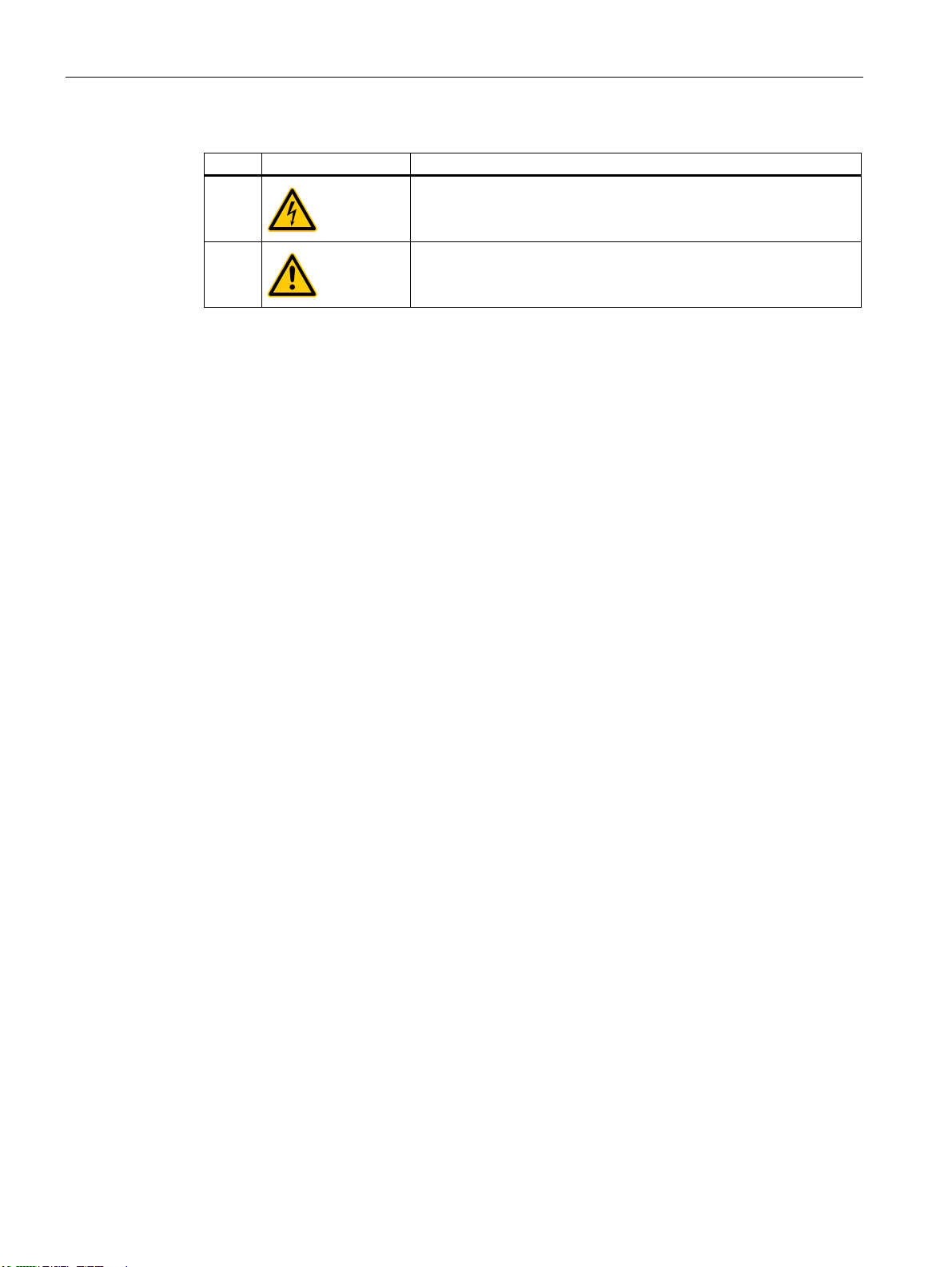
Figure 2-1 Safety-related symbols on the device
SENTRON PAC3100
Manual, 07/2009, A5E02385159B-01
13
Safety notes
Symbol Meaning
(1)
Risk of electric shock
See also
(2)
General Warning Symbol
Applying the supply voltage (Page 51)
Applying the measuring voltage (Page 60)
Applying the measuring current (Page 61)
SENTRON PAC3100
14 Manual, 07/2009, A5E02385159B-01

Description
3.1 Features
The SENTRON PAC3100 is a Power Monitoring Device for displaying the basic electrical
variables in low-voltage power distribution. It is capable of single-phase, two-phase, or threephase measurement and can be used in three-wire, four-wire, TN, TT, and IT systems.
Thanks to its compact design in 96 x 96 mm format, it is an ideal replacement for all
conventional analog indicating instruments.
Thanks to its large measuring voltage range, the SENTRON PAC3100 can be connected
direct in any low-voltage system up to a rated voltage of 480 V
Higher voltages can be measured using voltage transformers.
x / 5 A current transformers can be used for current measuring.
The large graphical LC display permits reading even from a distance.
The combination of four function keys with the multi-language plaintext displays makes
intuitive user prompting possible. The experienced operator can also use direct navigation
for quicker selection of the desired display menu.
The integrated RS 485 interface can be used for communication.
In addition, the SENTRON PAC3100 has 2 digital inputs and 2 digital outputs. The
parameters can be set either direct on the device or via the RS 485 interface.
L-L
3
.
Password protection is integrated via the front of the device to guard against unauthorized
access.
Device versions
The device is available in the following version:
Table 3- 1 Device versions
SENTRON PAC3100 Power Monitoring Device
Order No. Description
7KM3133-0BA00-3AA0 SENTRON PAC3100 with wide-range power supply and screw terminals
Measurement
● Derivation of more than 30 measured variables from the basic measured variables for
voltages and currents.
● The SENTRON PAC3100 can be connected direct to 480 V industrial systems
(measuring category III, pollution degree 2). Higher voltages using voltage transformers.
● Suitable for current transformers x / 5 A. Programmable conversion ratio and direction of
current.
SENTRON PAC3100
Manual, 07/2009, A5E02385159B-01
15

Description
3.1 Features
● Can be used in 3 and 4-wire systems. Suitable for TN, TT and IT systems.
● Measuring accuracy: Class 1 for voltages, currents, active power, apparent power, and
active energy (in accordance with IEC 61557-12)
● TRMS up to the 15th harmonic
Counters and power demand
● 4 energy counters record active energy and reactive energy. Optional display of 2
counters on the display.
● Calculation and storage of the last demand period mean value for active power and
reactive power for simple generation of load profiles using software. Programmable
demand period from 1 to 60 mins.
Display and operator control
● Large backlit graphics LC display for optimal readability even from a distance.
● Menu-driven parameterization and operation with plaintext display.
● Choice of output language for menu and text displays.
● Phase labels selectable (L1, L2, L3 <=> a, b, c).
Power supply
● AC/DC wide-range power supply:
Installation format
● Panel-mounting format 96 x 96 mm.
● Only 51 mm overall depth.
Interface
● Integral RS 485 Modbus RTU interface.
Inputs and outputs
● 2 digital inputs with internal power supply for status monitoring.
● 2 digital outputs, programmable as energy pulse outputs for active energy pulses or
Supply by 100 to 240 V AC ±10% / 50/60 Hz or
110 to 250 V DC ±10%.
reactive energy pulses, or as switching outputs for remote control via the RS 485
interface.
SENTRON PAC3100
16 Manual, 07/2009, A5E02385159B-01

Description
3.2 Measuring inputs
Protection
Password protection on the device by means of 4-character code.
See also
Measured variables (Page 21)
Technical data (Page 105)
3.2 Measuring inputs
Current measurement
CAUTION
AC current measurement only
The device is not suitable for measuring DC current.
SENTRON PAC3100 is designed for:
● Measuring current of 5 A for connecting standard current transformers. Each current
measuring input can take a continuous load of 10 A (max. 300 V). Surge withstand
capability is possible for currents up to 100 A and a duration of 1 s.
Voltage measurement
CAUTION
AC voltage measurement only
The device is not suitable for measuring DC voltage.
SENTRON PAC3100 is designed for:
● Direct measurement on the system or using voltage transformers. The measuring voltage
inputs of the device measure direct via protective impedances. External voltage
transformers are required to measure higher voltages than the permissible rated input
voltages.
● Measuring voltage up to 277 V / 480 V. The device is designed for measuring input
voltages up to 277 V to the neutral conductor and 480 V to the external conductor.
SENTRON PAC3100
Manual, 07/2009, A5E02385159B-01
17
Description
3.2 Measuring inputs
Connection types
Two connection types have been provided for connecting three-wire or four-wire systems
with unbalanced load.
Table 3- 2 Available connection types
Short code Connection type
3P4W 3 phases, 4 conductors, unbalanced load
3P3W 3 phases, 3 conductors, unbalanced load
The input circuit of the device must correspond to one of the connection types listed. Select
the suitable connection type for the purpose.
You can find connection examples in the chapter "Connection".
CAUTION
The wrong system connection can destroy the device
Before connecting SENTRON PAC3100, you must ensure that the local power supply
conditions agree with the specifications on the type plate.
The short code of the connection type must be entered in the device settings at startup. You
can find the instructions for parameterizing the connection type in the chapter
"Commissioning".
Display of the measured variables depending on the connection type
The total set of representable measured variables is restricted by the method of connecting
the device.
A measured value that cannot be indicated because of the connection method is shown on
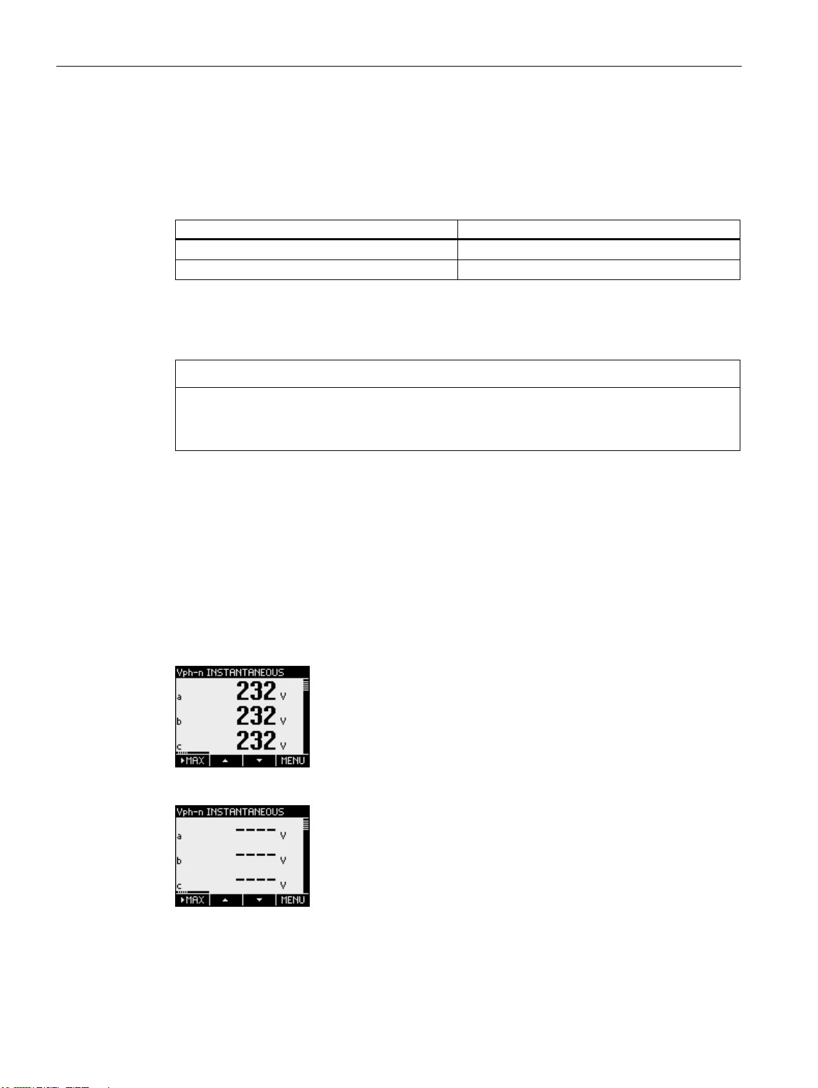
the display by means of a broken line "----".
Figure 3-1 Display of the measured voltage in the case of connection type 3P4W
Figure 3-2 Display of the measuring voltage in the case of connection type 3P3W
SENTRON PAC3100
18 Manual, 07/2009, A5E02385159B-01

Description
3.2 Measuring inputs
The table below shows which measured values can be represented depending on the
connection type.
Table 3- 3 Display of the measured variables depending on the connection type
Connection type
Measured variable
Voltage a-n ✓
Voltage b-n ✓
Voltage c-n ✓
Voltage a-b ✓ ✓
Voltage b-c ✓ ✓
Voltage c-a ✓ ✓
Current a ✓ ✓
Current b ✓ ✓
Current c ✓ ✓
Neutral current ✓
Apparent power a ✓
Apparent power b ✓
Apparent power c ✓
Active power a ✓
Active power b ✓
Active power c ✓
Reactive power a (VAR1) ✓
Reactive power b (VAR1) ✓
Reactive power c (VAR1) ✓
Total apparent power over all phases ✓ ✓
Total active power over all phases ✓ ✓
Total reactive power VAR1 over all phases ✓ ✓
Total power factor ✓ ✓
Line frequency ✓ ✓
Active energy ✓ ✓
Reactive energy ✓ ✓
Cumulated active power ✓ ✓
Cumulated reactive power ✓ ✓
3P4W 3P3W
SENTRON PAC3100
Manual, 07/2009, A5E02385159B-01
19
Description
3.2 Measuring inputs
Overload display
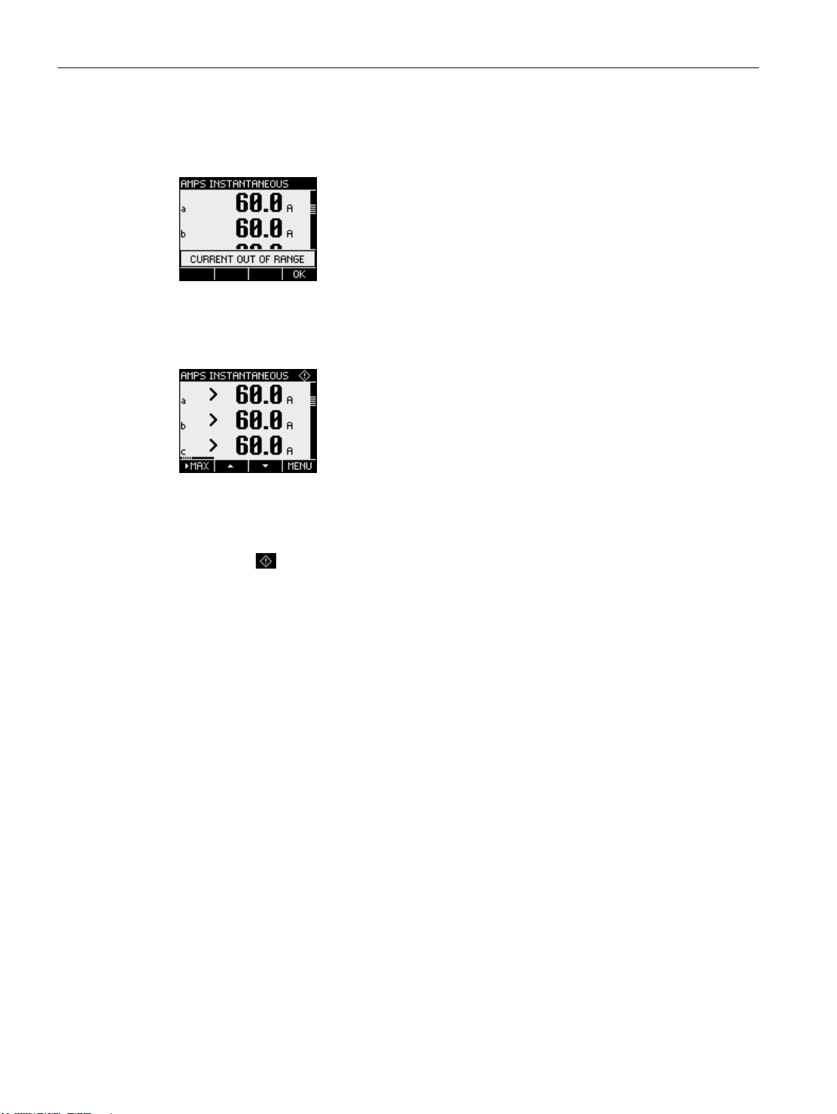
Voltage or current overload are indicated on the display:
Figure 3-3 Indicating overload on the display
The display shows the message "... OUT OF RANGE". The message can be confirmed and
hidden with function key <F4>.
Current direction
See also
Figure 3-4 Display of the measurable maximum value at overload
The character ">" and the measurable maximum value (physical measuring range multiplied
by scaling) are displayed instead of the measured values for affected phases.
The symbol
in the header indicates overload. The symbol can be seen in all measured
value displays.
The current direction can be changed on the device for all phases individually. It is not
necessary to change the terminal connections of the current transformers in the event of
connection errors.
Connection examples (Page 45)
Setting the connection type (Page 55)
Connection (Page 39)
Applying the measuring voltage (Page 60)
Applying the measuring current (Page 61)
SENTRON PAC3100
20 Manual, 07/2009, A5E02385159B-01

Description
3.3 Measured variables
3.3 Measured variables
Measured variables – overview
The table below lists all measured variables that the device records or derives from basic
variables.
Table 3- 4 Measured variables
Measured variable Abbreviation Instantan
eous
Min Max Mean
value
Total
value
Unit
value
Voltage ph-n V
Voltage ph-ph V
a-n
a-b
/ V
/ V
b-n
b-c
/ V
✓ ✓ ✓ [V]
c-n
/ V
✓ ✓ ✓ [V]
c-a
Current Ia / Ib / Ic ✓ ✓ ✓ [A]
Neutral current IN ✓ ✓ ✓ [A]
Apparent power per phase VAa / VAb / VAc ✓ ✓ ✓ [VA]
Active power per phase
Wa / Wb / Wc ✓ ✓ ✓ [W]
import/export
Reactive power (VAR1) per
phase positive / negative
Total apparent power over all
VAR
VAR
/ VAR
1 a
1 c
1 b
/
✓ ✓ ✓ [VAR]
VA ✓ ✓ ✓ [VA]
phases
Total active power over all
P ✓ ✓ ✓ ✓1) [W]
phases import / export
Total reactive power VAR1
Q1 ✓ ✓ ✓ ✓
1)
[VAR]
over all phases positive /
negative
Total power factor PF ✓ ✓ ✓
Line frequency f ✓ ✓ ✓ [Hz]
Active energy
Ea ✓ [Wh]
import/export/balance
Reactive energy
Er ✓ [VARh]
import/export/balance
1) Power demand of the last completed period for import and export, as well as minimum and maximum instantaneous
value. Can only be called via RS 485 interface. See the chapter "Power demand".
See also
Measured variables (Page 119)
Power demands and counters (Page 22)
SENTRON PAC3100
Manual, 07/2009, A5E02385159B-01
21

Description
3.4 Power demands and counters
3.4 Power demands and counters
3.4.1 Acquisition of power demand
Values that can be read out
SENTRON PAC3100 supplies the power demand of the last completed measuring period:
● Mean values for active power and reactive power, separated in each case for import and
export
● Minimum and maximum active power and reactive power
● Length of the demand period in seconds. The period may be shorter for reasons of
external synchronization.
● Time in seconds since the last synchronization or since completion of the last period.
Example: Period length and length of the demand period
Period length: 15 minutes; time of day: 13:03; time in seconds: 180 s.
The following can be calculated from this: The last demand period ended at 13:00. The
active demand period will end at 13:15 or in 12 minutes.
Availability
Note
The power demand of the last measuring period can only be fetched during the current
measuring period.
Note
The power demand can only be read out via the RS 485 interface. The values are not shown
on the display.
You can find more information on accessing the data via MODBUS in the Appendix.
Adjustable parameters
● Time interval in minutes: 1 to 60 min adjustable, default 15 min
● Synchronization via RS 485 interface
See also
Modbus RTU (Page 125)
SENTRON PAC3100
22 Manual, 07/2009, A5E02385159B-01

Description
3.5 Digital inputs and outputs
3.4.2 Energy counters
Energy counters
SENTRON PAC3100 has energy counters for counting
● Active energy import
● Active energy export
● Reactive energy import
● Reactive energy export
The device also calculates the energy balance
● Active energy balance
● Reactive energy balance
The energy balance is calculated from: Import minus export.
Availability
Two of the 6 variables can be represented on the display and read out via the interface. The
selection can be made when parameterizing the device.
3.4.3 Behavior in the case of power failure and power restore
After a power failure, the device starts back at zero with the calculation of the power demand
of the total active power and total reactive power.
Counter statuses and maximum/minimum values are written from the volatile to the nonvolatile memory at the following intervals:
Counter values Every 5 mins.
Maximum/minimum values Every 5 secs., if available
3.5 Digital inputs and outputs
The SENTRON PAC3100 has:
● 2 digital inputs
● 2 digital outputs
SENTRON PAC3100
Manual, 07/2009, A5E02385159B-01
23
Description
3.5 Digital inputs and outputs
3.5.1 Digital inputs
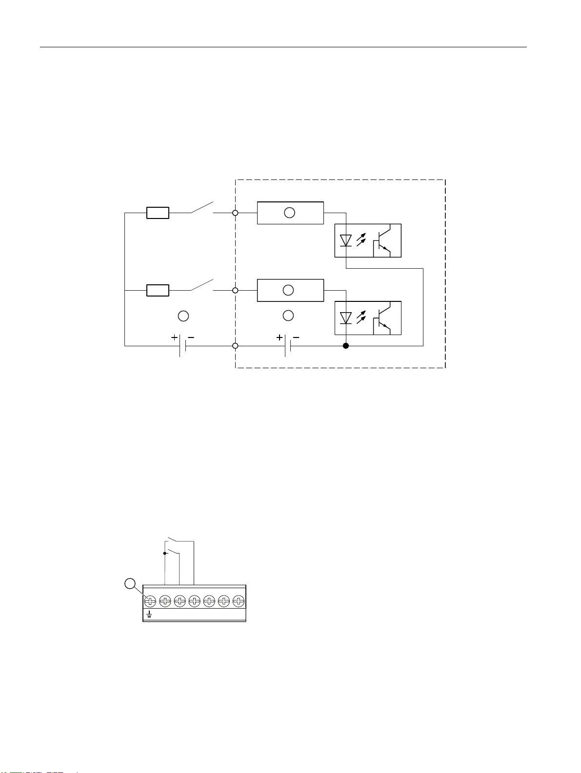
Function
Both digital inputs have the following function:
● Status monitoring: Capturing statuses of connected signal encoders
6
Wiring
5/
',
6
5/
',
',&
(1) Internal power supply
(2) Optional additional voltage power supply, max. 30 V, typically 24 V
(3) Input electronics
Figure 3-5 Block diagram: Digital inputs
Both digital inputs have an internal power supply. They can be operated optionally with or
without an external power supply.
Switch with internal power supply
Internal power supply on terminal DIC.
DIC DI0DI1 DOC
(1) Functional ground terminal
Figure 3-6 Digital inputs with switch and internal power supply on terminal DIC
SENTRON PAC3100
DO1
DO0
24 Manual, 07/2009, A5E02385159B-01
Description
3.5 Digital inputs and outputs
Switch with external power supply
In addition to the internal voltage on terminal DIC, and external voltage up to 30 V (typically
24 V) can be applied to terminal DIC.
DI1
DIC DI0
(1) Functional ground terminal
(2) External voltage
Figure 3-7 Digital inputs with switch, internal power supply, and additional external power supply on
DOC
DO1
terminal DIC
DO0
3.5.2 Digital outputs
Functions
The following functions can be assigned to both digital outputs:
● Energy pulse output, programmable for active or reactive energy
● Switching output for remote control via the RS 485 interface
Energy pulse output
The digital output supplies a number of pulses proportional to one of the following energies:
● Active energy import
● Active energy export
● Reactive energy import
● Reactive energy export
Figure 3-8 Energy pulse output
SENTRON PAC3100
Manual, 07/2009, A5E02385159B-01
25
Description
3.6 RS 485 interface
Remote control via the RS 485 interface
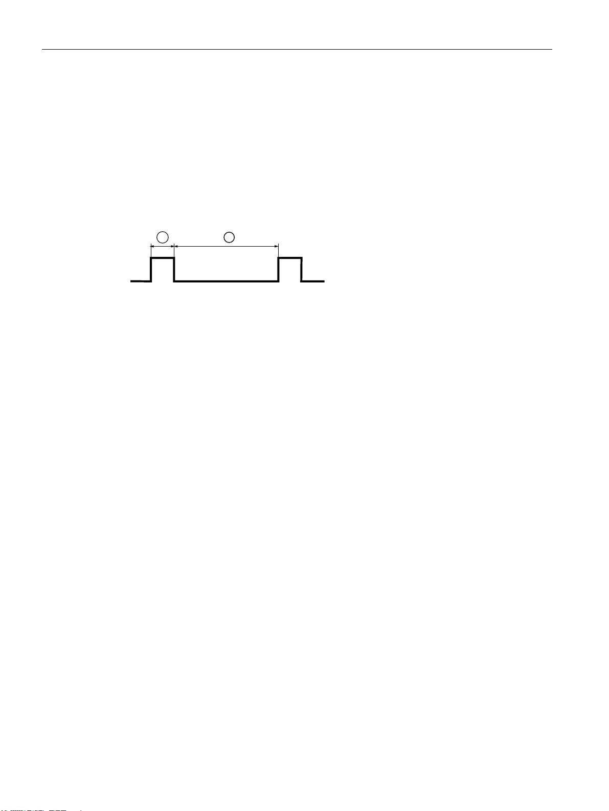
The integral RS 485 interface enables remote control of the digital outputs. The Modbus
function codes are listed in the Appendix.
Wiring
Both digital outputs are passive and implemented exclusively as switches.
Implementation of the pulse function corresponds to the IEC 62053-31 standard.
Pulse length, turn-off time
See also
(1) Pulse length
(2) Turn-off time
Figure 3-9 Pulse length and turn-off time
● Pulse length:
Time for which the signal at the digital output is "high". The minimum pulse length is
30 ms and the maximum 500 ms.
● Turn-off time:
Time for which the signal at the digital output is "low". The turn-off time depends on the
measured energy, for example, and can be days or months.
● Minimum turn-off time:
The minimum turn-off time corresponds to the programmed pulse length. 30 ms is the
absolute minimum.
Modbus RTU (Page 125)
3.6 RS 485 interface
RS 485 interface for Modbus RTU communication
The SENTRON PAC3100 is equipped with an RS 485 interface for Modbus RTU
communication.
Application
This interface permits:
● Reading out the measured values
● Reading and writing the device settings
SENTRON PAC3100
26 Manual, 07/2009, A5E02385159B-01

Description
3.6 RS 485 interface
● Device firmware updates
● Update of the languages available on the device
The Modbus function codes are listed in the Appendix.
Function
The device operates as a Modbus slave.
Conditions for operation
To use the interface, the device must be parameterized in accordance with the existing
Modbus infrastructure. The communication parameters can be set on the device and via the
Modbus RTU interface.
Default communication settings
In the as-delivered state, the following default values are set:
Table 3- 5 Default Modbus RTU communication settings
Setting Default value
Address 126
Baud rate 19200
Data format 8N2
Response time 0 (automatic)
Response time delay
The response time of the PAC3100 may have to be delayed to enable its operation as a
slave device with devices from other manufacturers on the bus. The PAC3100 can
automatically calculate the response time to suit the baud rate. This automatic calculation is
set at the factory. The delay time is individually adjustable between 1 and 255 milliseconds.
Polarization
Polarization of the RS 485 data lines must be implemented at another point on the bus. The
PAC3100 does not contain polarization resistors.
SENTRON PAC3100
Manual, 07/2009, A5E02385159B-01
27

Description
3.7 Slots on the rear of the device
Status LED
Two LEDs signal status information:
Table 3- 6 Meaning of the LED signals
Color State Description
Green and yellow Off No activity on the bus.
Green Flashing Other devices are communicating on the bus.
Yellow Flashing The SENTRON PAC3100 is sending data.
See also
Connecting to the RS 485 bus (Page 48)
Modbus RTU (Page 125)
3.7 Slots on the rear of the device
Slot on the rear of the device
CAUTION
The device can be destroyed if objects are inserted
Do not insert any objects into the housing slots on the rear of the device.
Figure 3-10 Non-usable housing openings
SENTRON PAC3100
28 Manual, 07/2009, A5E02385159B-01
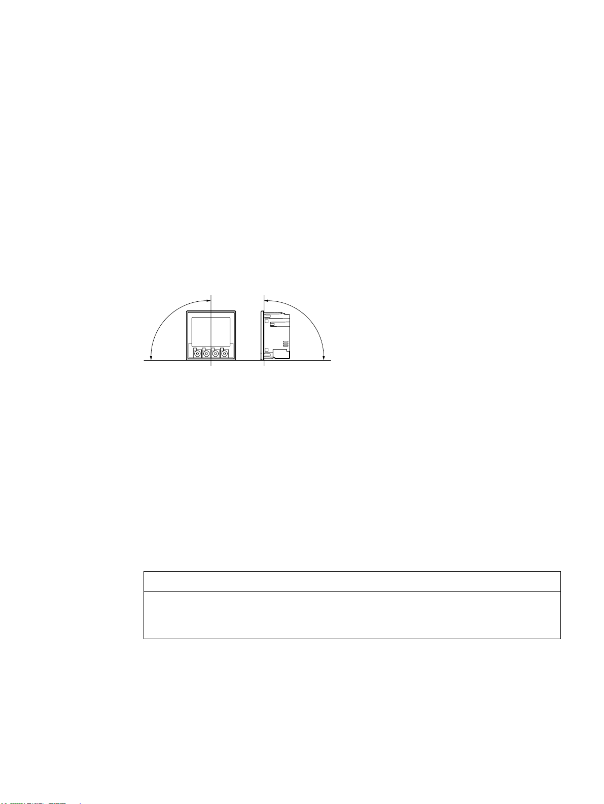
Operation planning
Mounting location
The SENTRON PAC3100 device is intended for installation in permanently installed
switching panels within closed rooms.
Conductive panels and doors on control cabinets must be grounded. The doors of the control
cabinet must be connected to the control cabinet using a grounding cable.
Mounting position
The device must be installed vertically.
r
Figure 4-1 Mounting position
The preferred direction of viewing is from below at an angle.
4
r
Installation space and ventilation
Sufficient clearance must be maintained between the device and neighboring components in
order to comply with the permissible operating temperature. You can find dimension
specifications in the "Dimensional drawings" chapter.
Plan additional space for:
● Ventilation
● Wiring
● RS 485 terminal block and cable infeed on the top of the device
CAUTION
Ensure ventilation
Please ensure that the ventilation slots of the housing are not obstructed. The wiring, cable
feed or other components must not obstruct ventilation.
SENTRON PAC3100
Manual, 07/2009, A5E02385159B-01
29

Operation planning
Environmental conditions
Use the SENTRON PAC3100 device only where environmental conditions permit its
operation:
Table 4- 1 Environmental conditions
Temperature range
Operating temperature - 10 °C through + 55 °C
Storage and transport temperature - 25 °C through + 70 °C
Relative humidity 95% at 25°C without condensation (normal
conditions)
Installation altitude above sea level max. 2000 m
Degree of pollution 2
Degree of protection according to IEC 60529
Device front IP65
Type 5 enclosure acc. to UL50
Device rear IP20
Circuit breaker
A suitable circuit breaker must be connected upstream of SENTRON PAC3100 in order to
permit disconnection of the device from the power supply!
● The circuit breaker must be mounted close to the device and be easily accessible to the
user.
● The circuit breaker must be marked as the circuit breaker for the device.
Temperature compensation
To avoid condensation, the device must be stored at the operating location for at least 2
hours before power is connected.
See also
Dimensional drawings (Page 115)
SENTRON PAC3100
30 Manual, 07/2009, A5E02385159B-01
 Loading...