

Siemens SENTRON PAC2200 Product Manual


___________________
___________________
___________________
___________________
___________________
___________________
___________________
___________________
___________________
___________________
SENTRON
7KM measuring device
PAC2200
Manual
05/2018
L1V30415167B
Introduction
1
Description
2
Mounting
3
Connection
4
Operation
5
Commissioning
6
Service and maintenance
7
Technical data
8
Dimension drawings
9
Appendix
A
-02

Siemens AG
Division Energy Management
Postfach 32 20
91050 ERLANGEN
GERMANY
Document order number: 3ZW1012-7KM22-0AC1
Ⓟ
Copyright © Siemens AG 2017.
All rights reserved
Legal information
Warning notice system
DANGER
indicates that death or severe personal injury will result if proper precautions are not taken.
WARNING
indicates that death or severe personal injury may result if proper precautions are not taken.
CAUTION
indicates that minor personal injury can result if proper precautions are not taken.
NOTICE
indicates that property damage can result if proper precautions are not taken.
Qualified Personnel
personnel qualified
Proper use of Siemens products
WARNING
Siemens products may only be used for the applications described in the catalog and in the relevant technical
ambient conditions must be complied with. The information in the relevant documentation must be observed.
Trademarks
Disclaimer of Liability
This manual contains notices you have to observe in order to ensure your personal safety, as well as to prevent
damage to property. The notices referring to your personal safety are highlighted in the manual by a safety alert
symbol, notices referring only to property damage have no safety alert symbol. These notices shown below are
graded according to the degree of danger.
If more than one degree of danger is present, the warning notice representing the highest degree of danger will
be used. A notice warning of injury to persons with a safety alert symbol may also include a warning relating to
property damage.
The product/system described in this documentation may be operated only by
task in accordance with the relevant documentation, in particular its warning notices and safety instructions.
Qualified personnel are those who, based on their training and experience, are capable of identifying risks and
avoiding potential hazards when working with these products/systems.
Note the following:
for the specific
documentation. If products and components from other manufacturers are used, these must be recommended
or approved by Siemens. Proper transport, storage, installation, assembly, commissioning, operation and
maintenance are required to ensure that the products operate safely and without any problems. The permissible
All names identified by ® are registered trademarks of Siemens AG. The remaining trademarks in this publication
may be trademarks whose use by third parties for their own purposes could violate the rights of the owner.
We have reviewed the contents of this publication to ensure consistency with the hardware and software
described. Since variance cannot be precluded entirely, we cannot guarantee full consistency. However, the
information in this publication is reviewed regularly and any necessary corrections are included in subsequent
editions.
05/2018 Subject to change

Table of contents
1 Introduction ................................................................................................................................................ 7
2 Description ............................................................................................................................................... 11
3 Mounting .................................................................................................................................................. 37
4 Connection .............................................................................................................................................. 39
1.1 Components of the product ...................................................................................................... 7
1.2 Latest information ..................................................................................................................... 7
2.1 Features .................................................................................................................................. 11
2.2 Measuring inputs ..................................................................................................................... 15
2.3 Averaging measured values ................................................................................................... 19
2.3.1 Acquisition of power demand .................................................................................................. 20
2.3.2 Energy counters ...................................................................................................................... 21
2.4 Digital inputs and outputs ....................................................................................................... 22
2.4.1 Digital input ............................................................................................................................. 22
2.4.2 Digital output ........................................................................................................................... 23
2.5 Communication ....................................................................................................................... 24
2.5.1 Ethernet .................................................................................................................................. 25
2.5.2 RS 485 .................................................................................................................................... 26
2.5.3 M-BUS .................................................................................................................................... 26
2.5.3.1 Three-phase connection (3P4W) ............................................................................................ 28
2.5.3.2 Single-phase connection (1P2W) ........................................................................................... 34
3.1 Introduction ............................................................................................................................. 37
3.2 Installation steps ..................................................................................................................... 38
3.3 Deinstallation .......................................................................................................................... 38
4.1 Safety notes ............................................................................................................................ 39
4.2 Connections ............................................................................................................................ 41
4.3 Connection examples ............................................................................................................. 43
4.4 Connecting the communication cable ..................................................................................... 45
4.4.1 Ethernet communication cable ............................................................................................... 45
4.4.2 RS 485 communication cable ................................................................................................. 46
4.4.3 M-Bus communication cable ................................................................................................... 46
4.4.4 Grounding of the Ethernet / RS 485 cable .............................................................................. 46
4.5 Gateway (slave) ...................................................................................................................... 48
PAC2200
Manual, 05/2018, L1V30415167B-02
3

Table of contents
5 Operation ................................................................................................................................................. 49
6 Commissioning ........................................................................................................................................ 57
7 Service and maintenance ........................................................................................................................ 71
8 Technical data ......................................................................................................................................... 75
9 Dimension drawings ................................................................................................................................ 85
A Appendix .................................................................................................................................................. 87
5.1 Device interface ..................................................................................................................... 49
5.1.1 Displays and operator controls .............................................................................................. 49
5.1.2 Control keys ........................................................................................................................... 50
5.2 Menu navigation ..................................................................................................................... 51
5.2.1 Measured value level ............................................................................................................. 51
5.2.2 Main menu level ..................................................................................................................... 52
5.2.3 Setting level ............................................................................................................................ 52
5.2.4 Editing level ............................................................................................................................ 52
5.3 Supporting software ............................................................................................................... 53
6.1 Overview ................................................................................................................................ 57
6.2 Applying the measuring voltage ............................................................................................. 58
6.3 Parameterizing the device ..................................................................................................... 58
6.3.1 Parameterizing with SENTRON powerconfig ........................................................................ 58
6.3.2 Setting parameters via the device menu ............................................................................... 62
7.1 Calibration .............................................................................................................................. 71
7.2 Firmware updates .................................................................................................................. 71
7.3 Troubleshooting guide ........................................................................................................... 72
7.4 Warranty ................................................................................................................................. 73
7.5 Disposal ................................................................................................................................. 73
8.1 Technical data ........................................................................................................................ 75
8.2 Labeling .................................................................................................................................. 83
9.1 Dimensional drawings ............................................................................................................ 85
A.1 Modbus TCP .......................................................................................................................... 87
A.1.1 Function codes ....................................................................................................................... 87
A.1.2 Modbus exception codes ....................................................................................................... 88
A.1.3 Modbus measured variables with the function codes 0x03 and 0x04 ................................... 89
A.1.4 Modbus-measured variables with function code "0x14" ........................................................ 92
A.1.5 Structure - Digital input status and digital output status with the function codes 0x03
and 0x04 ................................................................................................................................ 95
A.1.6 Structure - Device diagnostics and device status with the function codes 0x03 and
0x04 ....................................................................................................................................... 96
A.1.7 Modbus status parameters with the function code 0x02 ....................................................... 97
A.1.8 Modbus settings with the function codes 0x03, 0x04 and 0x10 ............................................ 98
A.1.9 Modbus communication parameters with the function codes 0x03, 0x04 and 0x10 ........... 101
A.1.10 Modbus device information with the function codes 0x03, 0x04 and 0x10.......................... 102
A.1.11 Modbus command parameters ............................................................................................ 104
PAC2200
4 Manual, 05/2018, L1V30415167B-02

Table of contents
Index ...................................................................................................................................................... 107
A.1.12 Modbus standard device identification with the function code 0x2B .................................... 105
PAC2200
Manual, 05/2018, L1V30415167B-02
5

Table of contents
PAC2200
6 Manual, 05/2018, L1V30415167B-02

1
1.1
Components of the product
Available accessories
1.2
Latest information
Up-to-the-minute information
on the Internet:
The package includes:
● 1 x PAC2200 measuring device
● PAC2200 operating instructions:
● SENTRON powerconfig software
(
powerconfig-v3-7?dti=0&lc=en-WW)
● SENTRON powermanager software
(
hf1?dti=0&lc=en-WW)
https://support.industry.siemens.com/cs/document/63452759/update-version-
https://support.industry.siemens.com/cs/document/64850998/powermanager-v3-3-incl-
You can find further assistance:
Website (https://support.industry.siemens.com/my/ww/en/requests)
PAC2200
Manual, 05/2018, L1V30415167B-02
7

Introduction
Third-party software information
1.2 Latest information
This product, solution or service ("Product") contains third-party software components listed
in this document. These components are Open Source Software licensed under a license
approved by the Open Source Initiative www.opensource.org (www.opensource.org
similar licenses as determined by SIEMENS ("OSS") and/or commercial or freeware
software components. With respect to the OSS components, the applicable OSS license
conditions prevail over any other terms and conditions covering the Product. The OSS
portions of this Product are provided royalty-free and can be used at no charge.
If SIEMENS has combined or linked certain components of the Product with/to OSS
components licensed under the GNU LGPL version 2 or later as per the definition of the
applicable license, and if use of the corresponding object file is not unrestricted ("LGPL
Licensed Module", whereas the LGPL Licensed Module and the components that the LGPL
Licensed Module is combined with or linked to is the "Combined Product"), the following
additional rights apply, if the relevant LGPL license criteria are met: (i) you are entitled to
modify the Combined Product for your own use, including but not limited to the right to
modify the Combined Product to relink modified versions of the LGPL Licensed Module, and
(ii) you may reverse-engineer the Combined Product, but only to debug your modifications.
The modification right does not include the right to distribute such modifications and you
shall maintain in confidence any information resulting from such reverse-engineering of a
Combined Product.
), or
Certain OSS licenses require SIEMENS to make source code available, for example, the
GNU General Public License, the GNU Lesser General Public License and the Mozilla Public
License. If such licenses are applicable and this Product is not shipped with the required
source code, a copy of this source code can be obtained by anyone in receipt of this
information during the period required by the applicable OSS licenses by contacting the
following address:
Siemens AG Energy Management, Low Voltage & Products
Siemensstrasse 10
93055 Regensburg
Germany
Internet: Technical Assistance (https://support.industry.siemens.com/My/ww/en/requests
Subject: Open Source Request (please specify Product name and version, if applicable)
SIEMENS may charge a handling fee of up to 5 EUR to fulfil the request.
)
PAC2200
8 Manual, 05/2018, L1V30415167B-02

Introduction
Warranty regarding further use of the Open Source Software
Security information
1.2 Latest information
SIEMENS' warranty obligations are set forth in your agreement with SIEMENS. SIEMENS
does not provide any warranty or technical support for this Product or any OSS components
contained in it if they are modified or used in any manner not specified by SIEMENS. The
license conditions listed below may contain disclaimers that apply between you and the
respective licensor. For the avoidance of doubt, SIEMENS does not make any warranty
commitment on behalf of or binding upon any third-party licensor.
Siemens provides products and solutions with industrial security functions that support the
secure operation of plants, systems, machines and networks.
In order to protect plants, systems, machines and networks against cyber threats, it is
necessary to implement – and continuously maintain – a holistic, state-of-the-art industrial
security concept. Siemens’ products and solutions constitute one element of such a concept.
Customers are responsible for preventing unauthorized access to their plants, systems,
machines and networks. Such systems, machines and components should only be
connected to an enterprise network or the Internet if and to the extent such a connection is
necessary and only when appropriate security measures (e.g. firewalls and/or network
segmentation) are in place.
For additional information on industrial security measures that may be implemented, please
visit
Industrial security (http://www.siemens.com/industrialsecurity
)
Siemens’ products and solutions undergo continuous development to make them more
secure. Siemens strongly recommends that product updates are applied as soon as they are
available and that the latest product versions are used. Use of product versions that are no
longer supported, and failure to apply the latest updates may increase customer's exposure
to cyber threats.
To stay informed about product updates, subscribe to the Siemens Industrial Security RSS
Feed under
Technical Support (https://support.industry.siemens.com/cs/start?lc=en-WW
)
PAC2200
Manual, 05/2018, L1V30415167B-02
9
Introduction
Note
Risk of manipulation
Several protective mechanisms can be activated in the device.
In order to reduce the
the protective mechanisms available in the device are activated.
•
•
See chapter
General safety instructions
DANGER
Hazardous Voltage
Will cause death or serious injury.
Safety-related symbols on the device
Symbol
Meaning
1.2 Latest information
risk of manipulation occurring on the device, it is recommended that
Password protection, to protect the device against unintentional adjustment of
parameters.
Hardware write protection, to effectively prevent changes to the device parameters
without physical access to the device.
Setting parameters via the device menu (Page 62)
Turn off and lock out all power supplying this device before working on it.
(1)
(2)
(3)
Risk of electric shock
General Warning Symbol
Electrical installation demands technical competence
PAC2200
10 Manual, 05/2018, L1V30415167B-02

2
2.1
Features
5 A device:
65 A device:
Measurement
Counters and power demand
The PAC2200 is a measuring device for measuring the basic electrical variables in lowvoltage power distribution. All measured variables are shown on the display of the PAC2200.
The device is capable of single-phase, two-phase, or three-phase measurement and can be
used in TN and TT networks.
The PAC2200 is mounted on a DIN rail.
The PAC2200 measuring device is available in several versions:
●
x / 1 A and x / 5 A current transformers can be used for current measuring.
●
No current transformers are required for current measuring. The device is connected directly
to the low-voltage network. Current of up to 65 A can be measured directly.
Depending on the device version, the PAC2200 measuring device has an integrated
Ethernet, RS485 or M-BUS interface.
Thanks to its large measuring voltage range, the PAC2200 measuring device can be
connected directly in any low-voltage system up to a voltage UL-L 480 V.
● Measurement of all relevant electrical variables in an AC system.
● Acquisition of minimum and maximum values of all measured variables.
● Averaging of all measured variables directly on the device in two steps, which are
independent of each other and freely configurable (aggregation).
● Recording of active, reactive and apparent energy by means of several energy counters
● Calculation and storage of the last measuring period demand for active power and
reactive power for simple generation of load profiles using software (programmable
measuring period of between 1 and 60 min.).
PAC2200
Manual, 05/2018, L1V30415167B-02
11

Description
Display and operator control
Interfaces
Memory
Response in the case of power failure and power restore
2.1 Features
● LC display
● Four control keys with variable function assignment
● LED for Ethernet communication, active energy pulse indicator
● SENTRON powerconfig from Version 3.7.
● SENTRON powermanager from Version 3.4.
● Web server (HTTP) (optional)
● Ethernet (optional)
● RS 485 interface (optional)
● M-BUS (optional)
● Digital input
● Digital output
● Adjusted device parameters are permanently stored in the device memory.
● Extreme values (maximum or minimum) are permanently stored in the internal device
memory. Values can be reset via SENTRON powerconfig, Modbus command or directly
on the device via the menu.
After a power failure, the device starts back at zero with the calculation of the power demand
of the
total active power and total reactive power.
Counter statuses and extreme values are written from the volatile to the
non-volatile memory at the following intervals:
Counter values Every 5 mins.
Extreme values Every 5 secs., if available
PAC2200
12 Manual, 05/2018, L1V30415167B-02

Description
Security
Note
Activate hardware write protection
When connecting the measuring device to a network, it is recommended that the hardware
write protection is activated.
2.1 Features
● Hardware write protection
● Password protection
● Access protection, IP filter
● Modbus TCP port, configurable
● HTTP port, configurable
● DHCP protocol included
● SNTP protocol included
● Attachment of lead seals possible
Using "Password protection" and "Hardware write protection", you can protect against write
access to the device settings of the PAC2200.
The protection takes effect in case of the following actions:
● Modify parameters in device
● Reset maximum
● Reset minimum
● Reset counter
● Reset device
● Reset device to factory defaults
● Reset password
● Update firmware on the device
The data can be read without any restrictions.
PAC2200
Manual, 05/2018, L1V30415167B-02
13

Description
Tariffs
MID-approved
See also
2.1 Features
SENTRON PAC2200 supports 2 tariffs for the integrated energy counter (on-peak and
off-peak).
Switching between tariffs
Tariff switching can be controlled via the digital input or the
communication interfaces.
Time-related switching is only possible using a higher-level system.
Tariff switching after synchronization
When synchronizing the power demand values via the communication interfaces
or the digital input, the tariff change will only become effective after expiry of the
period. Without synchronization, the tariff change takes effect immediately.
The synchronization frame contains the length of the demand period in minutes. The
synchronization command is ignored if the period length sent to the device with the
synchronization frame is different to the length parameterized in the device.
MID-approved devices are included in the portfolio. These devices are suitable for billing the
active energy.
The following actions cannot be carried out on MID-approved devices:
● FW update
● Resetting the secondary energy values
● Parameterization of the voltage input
● Inversion of the direction of current flow
The secondary value of the total active energy is suitable for billing purposes.
Energy counters (Page 21)
PAC2200
14 Manual, 05/2018, L1V30415167B-02

Description
2.2
Measuring inputs
Current measurement
NOTICE
AC current measurement only
Measuring current of 5 A for connecting standard current transformers.
Direct connection to the low-voltage network
Voltage measurement
NOTICE
AC voltage measurement only
Direct measurement on the network
Measurement voltage up to 277 V / 480 V
2.2 Measuring inputs
The device is not suitable for measuring DC current.
The 5 A device is designed for:
●
measuring input can take a continuous load of 10 A. A momentary overcurrent of up to
100 A and a duration of 1 s is possible.
The current direction can be changed for each phase individually. It is not necessary to
change the terminal connections of the current transformers in the event of connection
errors.
Each current
The 65 A device is designed for:
●
The device is not suitable for measuring DC voltage.
PAC2200 is designed for:
●
●
voltages up to 277 V to the neutral conductor and for measuring input voltages up to
480 V to the external conductor.
.
.
. The device is designed for measuring input
PAC2200
Manual, 05/2018, L1V30415167B-02
15

Description
Connection types
Short code
Connection type
3P4W (factory setting)
3 phases, 4 conductors, unbalanced load
NOTICE
The wrong system connection can destroy the device.
2.2 Measuring inputs
Two connection types have been provided. The device can be used in TN and IT networks.
Table 2- 1 Available connection types
1P2W (not MID devices) 1 phase, 2 conductors, unbalanced load
The input circuit of the device must correspond to one of the connection types listed. Select
the suitable connection type for the purpose.
Connection examples can be found in chapter Connection (Page 39)
Before connecting the PAC2200, you must ensure that the local power supply conditions
agree with the specifications on the rating plate.
The short code of the connection type must be entered in the device settings at startup. You
can find the instructions for parameterizing the connection type in chapter Commissioning
(Page 57).
PAC2200
16 Manual, 05/2018, L1V30415167B-02

Description
Display of the measured variables depending on the connection type
Connection type
Measured variable
3P4W
1P2W
Voltage L
1-N
✓
✓
Voltage L
✓
—
Voltage L
1-2
✓
—
Voltage L
✓
—
Voltage L
3-1
✓
—
Current L1
✓
✓
Current L2
✓
—
Current L3
✓
—
Apparent power L1
✓
✓
Apparent power L2
✓
—
Apparent power L3
✓
—
Active power L1
✓
✓
Active power L2
✓
—
Active power L3
✓
—
Reactive power L1
✓
✓
Reactive power L2
✓
—
Reactive power L3
✓
—
Total apparent power
✓
✓
Total active power
✓
✓
Total reactive power
✓
✓
Power factor L1
✓
✓
Power factor L3
✓
—
Frequency
✓
✓
Average voltage L - N
✓
—
2.2 Measuring inputs
The table below shows which measured values can be represented depending on the
connection type.
The availability of the measured variables depends on the type of readout.
Depending on the device version, several different readout types are available:
● Device display
● ModbusTCP
● ModbusRTU
● M-Bus
● Web server
Table 2- 2 Display of the measured variables depending on the connection type
Voltage L
✓ —
2-N
3-N
2-3
PAC2200
Manual, 05/2018, L1V30415167B-02
Power factor L2 ✓ —
Total power factor ✓ ✓
17

Description
Connection type
Measured variable
3P4W
1P2W
Average voltage L - L
✓
—
Binary outputs
✓
✓
Binary inputs
✓
✓
Tariff ✓ ✓
Counter (configurable)
✓
✓
Active power import
✓
✓
Active power export (load profile)
✓
✓
Reactive power import (load profile)
✓
✓
Reactive power export (load profile)
✓
✓
Max. active power (load profile)
✓
✓
Min. active power (load profile)
✓
✓
Max. reactive power (load profile)
✓
✓
Min. reactive power (load profile)
✓
✓
Total active energy import tariff 1
✓
✓
Total active energy import tariff 2
✓
✓
Total active energy export tariff 1
✓
✓
Total active energy export tariff 2
✓
✓
Total reactive energy import tariff 1
✓
✓
Total reactive energy import tariff 2
✓
✓
Total reactive energy export tariff 1
✓
✓
Total reactive energy export tariff 2
✓
✓
Total apparent energy tariff 2
✓
✓
L1 active energy import tariff 2
✓
✓
L1 active energy export tariff 1
✓
✓
L1 active energy export tariff 2
✓
✓
L1 reactive energy import tariff 1
✓
✓
L1 reactive energy import tariff 2
✓
✓
L1 reactive energy export tariff 1
✓
✓
L1 reactive energy export tariff 2
✓
✓
L1 apparent energy tariff 1
✓
✓
L1 apparent energy tariff 2
✓
✓
L2 active energy import tariff 1
✓
—
L2 active energy import tariff 2
✓
—
L2 active energy export tariff 1
✓
—
L2 active energy export tariff 2
✓
—
L2 reactive energy import tariff 1
✓
—
L2 reactive energy import tariff 2
✓
—
L2 reactive energy export tariff 1
✓
—
2.2 Measuring inputs
Average current ✓ —
Total apparent energy tariff 1 ✓ ✓
L1 active energy import tariff 1 ✓ ✓
PAC2200
18 Manual, 05/2018, L1V30415167B-02

Description
Connection type
Measured variable
3P4W
1P2W
L2 reactive energy export tariff 2
✓
—
L2 apparent energy tariff 2
✓
—
L3 active energy import tariff 1
✓
—
L3 active energy import tariff 2
✓
—
L3 active energy export tariff 1
✓
—
L3 active energy export tariff 2
✓
—
L3 reactive energy import tariff 1
✓
—
L3 reactive energy import tariff 2
✓
—
L3 reactive energy export tariff 1
✓
—
L3 reactive energy export tariff 2
✓
—
L3 apparent energy tariff 1
✓
—
L3 apparent energy tariff 2
✓
—
Secondary total active energy (MID register)
✓
—
2.3
Averaging measured values
2.3 Averaging measured values
L2 apparent energy tariff 1 ✓ —
With appropriate load profiles, consumers can carry out a targeted optimization of their
energy consumption.
Instantaneous values are averaged over specific time periods to create load profiles. For this
purpose, measured values are read out via the communication and stored. This
increases the bus load considerably and occupies storage capacity.
The PAC2200 device has two average value generators, which can be parameterized
independently.
The aggregation of the measured values reduces the bus load without risk of loosing
information. Average values are calculated contiguously, based on the underlying values.
The values are updated each time after expiry of the set time period.
The default setting for average value 1 is a period length of 10 seconds.
The default setting for average value 2 is a period length of 15 minutes.
The period length can be set to anything between 3 seconds and 31536000 seconds (1
year).
This function is only available if communication interfaces via Modbus TCP/RTU are used.
The list of available measured values can be found in the appendix A.1.4 „Modbus variables
with function code 0x14“ on page 82 (Page 92).
PAC2200
Manual, 05/2018, L1V30415167B-02
19

Description
2.3.1
Acquisition of power demand
Values that can be read out
Example
Note
The power demand of the last measuring period can only be fetched during the current
measuring period.
Adjustable parameters
2.3 Averaging measured values
● The PAC2200 measuring device supplies the power demand of the last completed
measuring period:
● Mean values for active and reactive power, separately for import and export.
● Minimum and maximum active power and reactive power within the last measuring
period.
● Length of the measuring period in seconds. The period may be shorter for reasons of
external synchronization.
● Time in seconds since the last synchronization or since completion of the last period.
Period length: 15 minutes; time of day: 13:03; time in seconds: 180 s.
The following can be calculated from this: The last measuring period ended at 13:00. The
active measuring period will end at 13:15 or in 12 minutes.
Period length in minutes: 1 to 60 min adjustable, default 15 min
: Period length and length of the measuring period:
PAC2200
20 Manual, 05/2018, L1V30415167B-02

Description
2.3.2
Energy counters
Tariff 1
Tariff 2
Total
(T1 + T2)
Active energy kWh
Import
Total
X X X
L2 X X L3 X X Secondary value
X (MID)
Export
Total
X X X
L1 X X L2 X X L3 X X Secondary value
X
Reactive energy kvarh
Import
Total
X X X
L1 X X L2 X X L3 X X Secondary value
X
Export
Total
X X X
L1 X X L2 X X L3 X X
Secondary value
X
Apparent energy kVAh
L1 X X
L3 X X Secondary value
X
Secondary values
MID
YY
Indicates the year the MID marking was affixed
2.3 Averaging measured values
Available energy counters of the PAC2200 measuring device:
L1 X X
Total X X X
: Non-resettable energy counters. Transformer ratio is not taken into
L2 X X
account in the calculation.
: MID registers are marked in the menu with MID mark. Marked registers are suitable for
billing purposes.
PAC2200
Manual, 05/2018, L1V30415167B-02
21
Description
2.4
Digital inputs and outputs
1 digital input
1 digital output
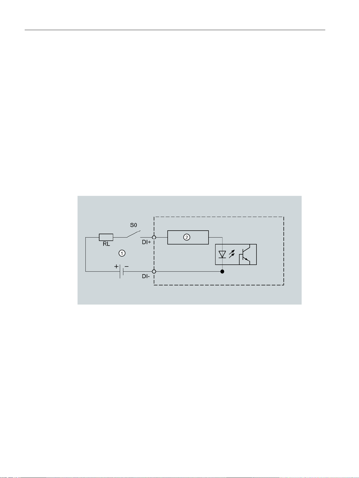
2.4.1
Digital input
(1)
External power supply, max. 30 VDC, typically 24 VDC
(2)
Input electronics
2.4 Digital inputs and outputs
The PAC2200 has the following inputs/outputs:
●
●
The following functions can be assigned to the digital input:
● Status monitoring: Capturing statuses of connected signal encoders
● Tariff switch for two-tariff counters.
● Synchronization of the measuring period by means of the synchronization pulse of a
system control center or other device.
● Input for energy pulses (S0 interface)
Figure 2-1 Block diagram: Digital inputs
PAC2200
22 Manual, 05/2018, L1V30415167B-02
Description
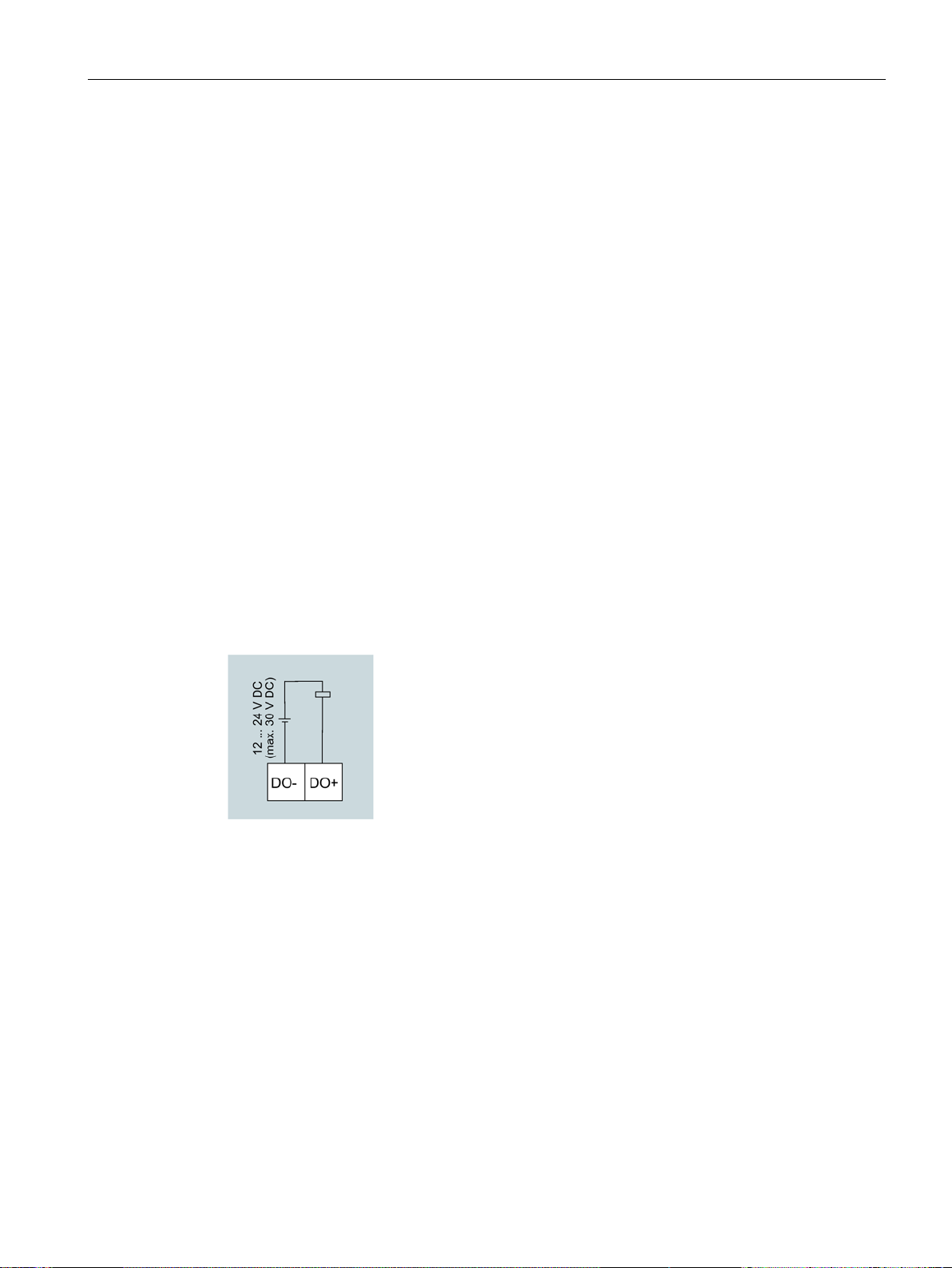
2.4.2
Digital output
2.4 Digital inputs and outputs
The following functions can be assigned to the digital output:
● Not used
Digital output is deactivated.
● Device is ready for operation.
The digital output is ON.
● Remote control
The digital input is remotely controlled.
● Direction of rotation
The digital output is switched on by a counter-clockwise rotating electrical field and
remains active while the direction of rotation of the field remains unchanged.
● Energy pulse
The digital output outputs the parameterized number of pulses per energy unit (e.g. kWh).
The specified energy counter is evaluated here.
Figure 2-2 Block diagram: Digital outputs
PAC2200
Manual, 05/2018, L1V30415167B-02
23

Description
Wiring
(1)
Pulse length
(2)
Turn-off time
2.5
Communication
Ethernet
RS 485
M-BUS
2.5 Communication
The digital output is passive and implemented exclusively as a switch.
Implementation of the pulse function corresponds to the IEC 62053-31 standard.
Figure 2-3 Pulse length and turn-off time
● Pulse length:
Time for which the signal at the digital output is "high". The minimum pulse length is
30 ms and the maximum 500 ms.
● Turn-off time:
Time for which the signal at the digital output is "low". The turn-off time depends on the
measured energy, for example, and can be days or months.
● Minimum turn-off time:
The minimum turn-off time corresponds to the programmed pulse length. 30 ms is the
absolute minimum.
Depending on the device version, the devices may be fitted with the following
communications interfaces:
●
●
●
The selection of the measured variables available for selection can vary according to the
communication mode selected.
PAC2200
24 Manual, 05/2018, L1V30415167B-02

Description
2.5.1
Ethernet
Modbus TCP
Web server (HTTP)
SNTP
DHCP
2.5 Communication
Permits communication via the following protocols:
●
The device can be configured via Modbus TCP
●
Protocol can be used to read out the measured values via web browser.
●
The SNTP (Simple Network Time Protocol) is used to automatically synchronize the internal
clock with a time server within the network.
Three function modes are available:
● No synchronization.
● Date/time synchronization via device request
The IP address of an NTP server must be configured. With this, the PAC2200
automatically requests the current time from the server and resets its internal clock, if
necessary.
● Date/time synchronization via SNTP server - Broadcast
The PAC2200 receives Broadcast time telegrams, which are sent from an NTP server.
This is practical, if the internal clocks in several devices in the same network
should be synchronous.
If the IP address of the NTP server has been configured, the PAC2200 only responds to
these telegrams. Furthermore, it can send a request to the server, if necessary.
●
Stands for "Dynamic Host Configuration Protocol". Protocol for obtaining network settings
from a DHCP server. Network settings are automatically assigned.
PAC2200
Manual, 05/2018, L1V30415167B-02
25

Description
2.5.2
RS 485
Note
RS 485 termination is recommended!
In order to avoid reflection on the bus cable, we recommend fitting a 120
resistor at the beginning and end of the bus cable.
2.5.3
M-BUS
2.5 Communication
Permits communication via the MODBUS RTU protocol. This interface features simple
topology and high immunity against EMC interference.
The data is transmitted differentially via two wires A and B. The third wire "COM" serves as
the common ground potential.
Grounding of the cable shield:
The serial Modbus data cable should be shielded. The shield should be connected to
protective ground at one end of the cable at least.
Grounding of the COM line:
Many masters do not have a common terminal. If this is the case, then RS 485 common
should reference the same functional ground as the master (at a single point). If the
master has a common terminal, then the common is connected to it, and it is not connected
to functional ground.
Ohm terminating
M-BUS is the abbreviation for Meter-Bus according to EN13757. The M-BUS is used as a
fieldbus for the acquisition of consumption data. The data is serially transmitted over a
reverse-polarity protected two-wire line.
PAC2200 data can be read out with an M-BUS master. The PAC2200 is then implemented
as an M-BUS slave.
To read out measurement data stored on the device, the slave address must be known.
The user can give a primary address to the device manually, or use the secondary address
of the device. The secondary address is automatically created from the serial number of the
device and must therefore not be set explicitly. Furthermore, the interface of the PAC2200
must be set to the baud rate used in your M-BUS system. Additionally the user can choose
between two different DIF / VIF codes ("mapping"). In "Mapping 1" the measured values are
coded in more detail with DIF / VIF with the result that all the data records have different
coding.
Different measurement data is available, depending on the connection type, 3P4W or 1P2W.
(With MID devices only connection type 3P4W is possible).
The connection type and the parameter setting in the M-BUS communications menu on the
device display define the data record structure or contents of the RSP_UD2 long datagram.
At the M-BUS interface the setting can be determined by means of the version number in the
header of the RSP_UD2 response datagram of an REQ_UD2 request (see M-BUS
specification)
PAC2200
26 Manual, 05/2018, L1V30415167B-02

Description
Header
Structure of RSP_UD2 datagram
es
es
Version 33
1-phase connection 1P2W
19 data records on 1 page
Mapping 1
2.5 Communication
Version 30 3-phase connection 3P4W 69 data records on 3 pag-
Version 31 1-phase connection 1P2W 19 data records on 1 page Mapping 0
Version 32 3-phase connection 3P4W 69 data records on 3 pag-
Mapping 0
Mapping 1
The factory setting when delivered is connection type "3P4W" with "Mapping 1".
If this setting is not changed the device addresses the M-BUS interface with version 32. The
device then supplies 69 data records on 4 pages (in 4 datagrams).
PAC2200
Manual, 05/2018, L1V30415167B-02
27

Description
2.5.3.1
Three-phase connection (3P4W)
L2 active energy export tariff 2
BYTE No.
Coding
Description
Byte 1
0x86
DIF value format INT48 -> Integer 6 bytes length
Byte 2
0x20
DIFE tariff 2
Byte 3
0x83
VIF active energy / unit Wh
Bytes 5-6
0xFC 0x02
VIFE phase L2
XX
(bits)
1
Secondary total active energy (MID register)
48
INT48
Wh
2
Total active energy import tariff 1
48
INT48
Wh 3 Total active energy import tariff 2
48
INT48
Wh 4 Total active energy export tariff 1
48
INT48
Wh 5 Total active energy export tariff 2
48
INT48
Wh 6 L1 active energy import tariff 1
48
INT48
Wh 7 L1 active energy import tariff 2
48
INT48
Wh 8 L1 active energy export tariff 1
48
INT48
Wh 9 L1 active energy export tariff 2
48
INT48
Wh
10
L2 active energy import tariff 1
48
INT48
Wh
11
L2 active energy import tariff 2
48
INT48
Wh
12
L2 active energy export tariff 1
48
INT48
Wh
13
L2 active energy export tariff 2
48
INT48
Wh
14
L3 active energy import tariff 1
48
INT48
Wh
16
L3 active energy export tariff 1
48
INT48
Wh
18
Total active power
32
FLOAT32
W
19
Active power L1
32
FLOAT32
W
20
Active power L2
32
FLOAT32
W
21
Active power L3
32
FLOAT32
W
22
Voltage L1-N
32
FLOAT32
V
2.5 Communication
The measurement data is presented on three pages (Mapping 0) and on four pages
(Mapping 1). Multipage-capable masters can read out all three or four pages.
As an example, the coding of the data record with ID 13 (connection type 3P4W, Mapping 1,
i.e. version 32) is more accurately explained in the RSP_UD2 response datagram (see also
M-BUS specification):
Measured variable ID 13:
Byte 4 0xBC VIFE export
Bytes 7-12 XX XX XX XX XX
Integer value of measured variable
All measurement data that can be read out via the M-BUS are listed in the following table.
ID
Measured variable
Length
Format
Unit
15 L3 active energy import tariff 2 48 INT48 Wh
17 L3 active energy export tariff 2 48 INT48 Wh
PAC2200
28 Manual, 05/2018, L1V30415167B-02
 Loading...