

Siemens SENTRON ATC6500 User Manual
3KC ATC6500 transfer control device


SENTRON
Transfer switching equipment and
load transfer switches
3KC ATC6500 transfer control
device
Manual
05/2019
L1V30538268002A
Introduction
1
General information
2
Applications
3
Product description
4
Functions
5
Installation
6
Connection
7
Operation
8
Parameterization
9
MODBUS communication
10
Accessories
11
Transfer
12
Technical specifications
13
Dimension drawings
14
ESD Guidelines
A
List of abbreviations
B
-01

Siemens AG
Smart Infrastructure
Low Voltage Products
Postfach 10 09 53
93009 REGENSBURG
GERMANY
Document order number: 3ZW1012-0KC00-5AC1
Ⓟ
Copyright © Siemens AG 2019.
All rights reser
DANGER
indicates that death or severe personal injury will result if proper precautions are not taken.
WARNING
indicates that death or severe personal injury may result if proper precautions are not taken.
CAUTION
indicates that minor personal injury can result if proper precautions are not taken.
NOTICE
indicates that property damage can result if proper precautions are not taken.
WARNING
Siemens products may only be used for the applications described in the catalog and in the relevant technical
ambient conditions must be complied with. The information in the relevant documentation must be observed.
Legal information
Warning notice system
This manual contains notices you have to observe in order to ensure your personal safety, as well as to prevent
damage to property. The notices referring to your personal safety are highlighted in the manual by a safety alert
symbol, notices referring only to property damage have no safety alert symbol. These notices shown below are
graded according to the degree of danger.
If more than one degree of danger is present, the warning notice representing the highest degree of danger will
be used. A notice warning of injury to persons with a safety alert symbol may also include a warning relating to
property damage.
Qualified Personnel
The product/system described in this documentation may be operated only by personnel qualified for the specific
task in accordance with the relevant documentation, in particular its warning notices and safety instructions.
Qualified personnel are those who, based on their training and experience, are capable of identifying risks and
avoiding potential hazards when working with these products/systems.
Proper use of Siemens products
Note the following:
documentation. If products and components from other manufacturers are used, these must be recommended
or approved by Siemens. Proper transport, storage, installation, assembly, commissioning, operation and
maintenance are required to ensure that the products operate safely and without any problems. The permissible
Trademarks
All names identified by ® are registered trademarks of Siemens AG. The remaining trademarks in this publication
may be trademarks whose use by third parties for their own purposes could violate the rights of the owner.
Disclaimer of Liability
We have reviewed the contents of this publication to ensure consistency with the hardware and software
described. Since variance cannot be precluded entirely, we cannot guarantee full consistency. However, the
information in this publication is reviewed regularly and any necessary corrections are included in subsequent
editions.
05/2019 Subject to change
ved

Table of contents
1 Introduction ............................................................................................................................................. 9
1.1 About this documentation ......................................................................................................... 9
1.2 Product-specific information ................................................................................................... 10
1.2.1 Certification ............................................................................................................................. 10
1.2.2 Reference documents ............................................................................................................. 11
1.2.3 Advanced training courses ..................................................................................................... 12
1.2.4 Technical Support ................................................................................................................... 12
1.3 Safety instructions ................................................................................................................... 13
1.3.1 Security information ................................................................................................................ 13
1.3.2 Open Source Software............................................................................................................ 14
2 General information .............................................................................................................................. 15
2.1 Features of the ATC6500 transfer control device ................................................................... 15
2.2 Compatible Siemens SENTRON switching devices ............................................................... 17
3 Applications .......................................................................................................................................... 19
3.1 Transfer control ....................................................................................................................... 19
3.1.1 Network/network application ................................................................................................... 19
3.1.2 Network/generator application ................................................................................................ 20
3.1.3 Generator/generator application ............................................................................................. 20
3.1.4 Load management with the ATC6500 .................................................................................... 20
3.1.4.1 Application A: 2S – 0T............................................................................................................. 21
3.1.4.2 Application B: 2S - 1T - PL ..................................................................................................... 22
3.1.4.3 Application C: 2S – 1T – SI ..................................................................................................... 23
3.1.4.4 Application D: 2S - 1T - AI ...................................................................................................... 24
3.1.4.5 Application O: 2S - NPL .......................................................................................................... 25
3.2 Controlling the switching devices ............................................................................................ 26
3.2.1 Controlling motor-driven circuit breakers ................................................................................ 27
3.2.2 Controlling remotely operated transfer switching equipment.................................................. 27
3.2.3 Controlling contactors ............................................................................................................. 28
3.3 Voltage measurement ............................................................................................................. 28
3.3.1 P02 General ............................................................................................................................ 29
3.3.2 P06 Source Lines .................................................................................................................... 29
3.3.3 P08 Switch .............................................................................................................................. 29
3.3.4 P09 Source Line CHK ............................................................................................................. 30
4 Product description ............................................................................................................................... 33
4.1 Status LEDs ............................................................................................................................ 34
4.2 Keys ........................................................................................................................................ 35
4.3 Interface .................................................................................................................................. 35
4.4 Menu navigation ...................................................................................................................... 36
3KC ATC6500 transfer control device
Manual, 05/2019, L1V30538268002A-01
3

Table of contents
4.5 Description of the main menu ................................................................................................ 36
4.5.1 Description of the symbols ..................................................................................................... 37
4.6 Navigation through the main menu ........................................................................................ 38
4.7 Display pages of the ATC6500 .............................................................................................. 38
4.7.1 Description of the display pages ............................................................................................ 38
4.7.1.1 Voltage L-L ............................................................................................................................. 39
4.7.1.2 L-N Voltage ............................................................................................................................ 39
4.7.1.3 Threshold limits ...................................................................................................................... 40
4.7.1.4 Alarms status ......................................................................................................................... 41
4.7.1.5 Statistics ................................................................................................................................. 41
4.7.1.6 Battery Status ......................................................................................................................... 42
4.7.1.7 Expansion modules ................................................................................................................ 42
4.7.1.8 Inputs/outputs......................................................................................................................... 43
4.7.1.9 Inputs ..................................................................................................................................... 43
4.7.1.10 Outputs ................................................................................................................................... 43
4.7.1.11 Date/Time ............................................................................................................................... 44
4.7.1.12 Information page 1 ................................................................................................................. 44
4.7.1.13 Event log ................................................................................................................................ 45
4.7.1.14 Counter CNTx ........................................................................................................................ 46
4.7.1.15 User limits LIMx...................................................................................................................... 46
4.7.1.16 Automatic test ........................................................................................................................ 47
4.7.1.17 Setup menu ............................................................................................................................ 47
4.7.1.18 Password ...............................................................................................................................
48
4.7.1.19 Commands menu ................................................................................................................... 48
4.7.1.20 Synchronoscope .................................................................................................................... 49
4.7.1.21 Synchronization...................................................................................................................... 49
4.7.1.22 Delta voltages ........................................................................................................................ 50
4.7.2 Scrolling through the display pages ....................................................................................... 50
5 Functions .............................................................................................................................................. 51
5.1 Basic functions ....................................................................................................................... 51
5.1.1 Setting the real-time clock ...................................................................................................... 51
5.1.2 Password protection .............................................................................................................. 52
5.1.2.1 Password protection against physical access ....................................................................... 52
5.1.2.2 Password protection against remote access (remote password) .......................................... 53
5.1.2.3 Entering the password via user interface ............................................................................... 53
5.1.3 Keypad lock ............................................................................................................................ 55
5.1.3.1 Activation of the keypad lock by means of a programmable input ........................................ 55
5.1.3.2 Activation of the keypad lock by means of a key combination on the operator panel ........... 55
5.1.4 Expandability by modules ...................................................................................................... 56
5.1.4.1 Enabling additional resources ................................................................................................ 57
5.1.4.2 Inserting an expansion module .............................................................................................. 58
5.1.4.3 Behavior of the ATC6500 after inserting a module ................................................................ 59
5.1.5 Communication COMx ........................................................................................................... 60
5.1.6 Alarms .................................................................................................................................... 61
5.1.6.1 Features of the alarms ........................................................................................................... 62
5.1.6.2 Alarm description ................................................................................................................... 63
5.1.6.3 Alarm table ............................................................................................................................. 65
5.1.6.4 User alarms UAx .................................................................................................................... 67
5.1.7 Automatic test ........................................................................................................................ 67
5.1.7.1 Enabling the automatic test .................................................................................................... 68
3KC ATC6500 transfer control device
4 Manual, 05/2019, L1V30538268002A-01

Table of contents
5.1.8 Simulation of priority source failure (test mode) ..................................................................... 69
5.1.9 Commands menu .................................................................................................................... 70
5.1.9.1 Executing a command ............................................................................................................ 70
5.1.9.2 Table of commands ................................................................................................................ 72
5.1.9.3 Event log ................................................................................................................................. 73
5.2 Advanced functions ................................................................................................................. 74
5.2.1 Remote variables REMx ......................................................................................................... 74
5.2.2 User limit LIMx ........................................................................................................................ 75
5.2.3 Timer TIMx .............................................................................................................................. 77
5.2.4 Counter CNTx ......................................................................................................................... 78
6 Installation ............................................................................................................................................ 79
6.1 Dimensions for the door cutout ............................................................................................... 79
6.2 Installation of the ATC6500 .................................................................................................... 80
7 Connection ........................................................................................................................................... 83
7.1 Connection of the power supply for the ATC6500 .................................................................. 83
7.1.1 Use of a DC source / battery .................................................................................................. 85
7.1.2 Power supply using a dual power supply................................................................................ 87
7.1.3 Power supply by means of UPS ............................................................................................. 88
7.1.4 Power supply by means of contactors .................................................................................... 89
7.2 General connection drawings ................................................................................................. 90
7.2.1 Transfer between 2 sources, with 2 breakers ......................................................................... 90
7.2.2 Transfer with 2 circuit breakers ............................................................................................... 91
7.2.3 Transfer with remotely operated transfer switching equipment .............................................. 92
7.2.4 Transfer with contactors.......................................................................................................... 94
7.2.5 Transfer between 2 sources, with 3 switching devices ........................................................... 95
7.2.6 Transfer with 3 circuit breakers ............................................................................................... 97
7.3 Connection of Siemens SENTRON switching devices ......................................................... 101
7.3.1 Accessories for switching devices ........................................................................................ 101
7.3.2 Accessories for mechanical interlock .................................................................................... 102
7.3.3 Technical specifications of the Siemens SENTRON switching devices (IEC only) .............. 105
7.3.4 Typical operating times of the Siemens SENTRON switching devices (IEC only) ............... 107
7.4 Connection of 3VA molded case circuit breakers ................................................................. 109
7.4.1 Connection of 3VA molded case circuit breakers with MO (IEC, UL), 3VA with SEO
(IEC only) .............................................................................................................................. 109
7.4.1.1 Transfer between two 3VA molded case circuit breakers, with electrical interlock .............. 109
7.4.1.2 Transfer between three 3VA molded case circuit breakers, with electrical interlock ........... 111
7.4.1.3 Transfer between three 3VA molded case circuit breakers, without electrical interlock ...... 113
7.4.2 Connection of 3VA27 motor-driven molded case circuit breakers (IEC only) ...................... 115
7.4.2.1 Transfer between two 3VA27 molded case circuit breakers, with electrical interlock .......... 115
7.4.2.2 Transfer between three 3VA27 molded case circuit breakers, with electrical interlock ....... 117
7.4.2.3 Transfer between three 3VA27 molded case circuit breakers, without electrical
interlock .................................................................................................................................
119
7.5 Connection of the 3WL air circuit breaker............................................................................. 121
7.5.1 Transfer between two 3WL10 air circuit breakers, with electrical interlock .......................... 121
7.5.2 Transfer between three 3WL10 air circuit breakers, with electrical interlock ....................... 123
7.5.3 Transfer between three 3WL10 air circuit breakers, without electrical interlock .................. 125
3KC ATC6500 transfer control device
Manual, 05/2019, L1V30538268002A-01
5

Table of contents
7.6 Connection of 3WL air circuit breakers, FS I - III ................................................................. 127
7.6.1 Transfer between two 3WL FS I-III air circuit breakers, with electrical interlock ................. 127
7.6.2 Transfer between three 3WL air circuit breakers FS I-III, with electrical interlock ............... 129
7.6.3 Transfer between three 3WL air circuit breakers FSI-III, without electrical interlock ........... 131
7.7 Connection of 3WT8 air circuit breakers .............................................................................. 133
7.7.1 Transfer between two 3WT8 air circuit breakers, with electrical interlock ........................... 133
7.7.2 Transfer between three 3WT8 air circuit breakers, with electrical interlock ........................ 135
7.7.3 Transfer between three 3WT8 air circuit breakers, without electrical interlock ................... 137
8 Operation ............................................................................................................................................. 139
8.1 Operating modes of the ATC6500 ....................................................................................... 139
8.1.1 Setting the operating mode .................................................................................................. 139
8.1.2 OFF mode (OFF) ................................................................................................................. 140
8.1.3 TEST mode .......................................................................................................................... 140
8.1.4 Manual mode (MAN) ............................................................................................................ 140
8.1.5 Automatic mode (AUT) ........................................................................................................ 143
8.2 Inputs and outputs of the ATC6500 ..................................................................................... 144
8.2.1 Voltage measuring inputs .................................................................................................... 144
8.2.2 Digital inputs INPx ................................................................................................................ 145
8.2.3 Table of functions of the digital inputs ................................................................................. 145
8.2.4 Digital outputs OUTx ............................................................................................................ 148
8.2.5 Table of functions of the digital outputs ............................................................................... 150
8.2.6 Addressing the expansion modules with digital inputs/outputs ........................................... 152
8.2.7 Integrated RS485 interface COM1....................................................................................... 152
9 Parameterization .................................................................................................................................. 155
9.1 Parameterization via the user interface ............................................................................... 155
9.2 Changing the parameters .................................................................................................... 158
9.3 Parameterization via the powerconfig software ................................................................... 158
9.3.1 Procedure for parameterization via powerconfig ................................................................. 158
9.3.2 Parameterization via the front interface ............................................................................... 159
9.3.3 Parameterization via the RS485 interface or the expansion modules for
communication ..................................................................................................................... 160
9.4 Parameters ........................................................................................................................... 160
9.4.1 P01 - Settings ....................................................................................................................... 161
9.4.2 P02 - General ....................................................................................................................... 162
9.4.3 P03 - Password .................................................................................................................... 165
9.4.4 P04 - Battery ........................................................................................................................ 166
9.4.5 P05 - Acoustic alarms .......................................................................................................... 167
9.4.6 P06 - Source Lines .............................................................................................................. 168
9.4.7 P07 - Breakers ..................................................................................................................... 169
9.4.8 P08 - Switch ......................................................................................................................... 171
9.4.9 P09 - Control thresholds of the source lines ........................................................................ 174
3KC ATC6500 transfer control device
6 Manual, 05/2019, L1V30538268002A-01

Table of contents
9.4.10 P10 - Communications.......................................................................................................... 177
9.4.11 P11 - Automatic Test ............................................................................................................ 178
9.4.12 P12 - Digital Inputs ................................................................................................................ 179
9.4.13 P13 - Digital Outputs ............................................................................................................. 180
9.4.14 P14 - Miscellaneous .............................................................................................................. 180
9.4.15 P15 - User limit thresholds LIMx ........................................................................................... 181
9.4.16 P16 - Counter CNTx ............................................................................................................. 182
9.4.17 P17 - Timer TIMx .................................................................................................................. 183
9.4.18 P21 - User Alarms ................................................................................................................. 184
10 MODBUS communication ................................................................................................................... 185
10.1 General information on MODBUS ........................................................................................ 185
10.2 MODBUS RTU protocol ........................................................................................................ 185
10.3 MODBUS functions ............................................................................................................... 186
10.3.1 Function 04: Read input register ........................................................................................... 187
10.3.2 Function 06: Preset single register ....................................................................................... 188
10.3.3 Function 07: Read exception status ..................................................................................... 188
10.3.4 Function 16: Preset multiple register .................................................................................... 189
10.3.5 Function 17: Report Slave ID ................................................................................................ 190
10.3.6 Password entry by means of MODBUS ................................................................................ 191
10.4 Data library ............................................................................................................................ 192
10.4.1 Measured values (use with MODBUS function 03 and 04) .................................................. 192
10.4.2 Status bits (use with MODBUS function 03 and 04) ............................................................. 194
10.4.3 Commands (use with MODBUS function 06) ....................................................................... 199
10.4.4 Status of the ATC (use with MODBUS function 03 and 04) ................................................. 201
10.4.5 Real-time clock (use with MODBUS function 04 and 06) ..................................................... 201
10.5 Reading the event log ........................................................................................................... 202
10.6 Reading parameters by means of MODBUS ........................................................................ 204
10.7 Changing parameters by means of MODBUS ...................................................................... 205
11 Accessories ........................................................................................................................................ 209
11.1 Expansion modules ............................................................................................................... 209
11.1.1 Expansion module 4DI - 3KC9000-8TL60 ............................................................................ 210
11.1.2 Technical specifications 4DI ................................................................................................. 212
11.1.3 Expansion module 4DO - 3KC9000-8TL61 .......................................................................... 213
11.1.4 Technical Specifications 4DO ............................................................................................... 214
11.1.5 Expansion module 2DI 2DO - 3KC9000-8TL62 ................................................................... 215
11.1.6 Technical Specifications 2DI 2DO ........................................................................................ 216
11.1.7 Expansion module 2DO - 3KC9000-8TL63 .......................................................................... 218
11.1.8 Technical Specifications 2DO ............................................................................................... 219
11.1.9 Expansion module 2DI 2DO - 3KC9000-8TL64 ................................................................... 220
11.1.10 Technical Specifications 2DI 2DO ........................................................................................ 221
11.1.11 Expansion module Ethernet - 3KC9000-8TL75 .................................................................... 223
11.1.12 Technical Specifications Ethernet ......................................................................................... 224
11.2 IP protective seal - 3KC9000-8TL68 ..................................................................................... 225
11.3 USB front interface - 3KC9000-8TL73 .................................................................................. 225
3KC ATC6500 transfer control device
Manual, 05/2019, L1V30538268002A-01
7

Table of contents
12 Transfer ............................................................................................................................................... 227
12.1 Transfer types ...................................................................................................................... 227
12.1.1 Open transition ..................................................................................................................... 227
12.1.2 IN-PHASE transition ............................................................................................................ 228
12.2 Transfer sequence ............................................................................................................... 229
12.2.1 Transfer sequence for application A: 2S - 0T ...................................................................... 229
12.2.2 Transfer sequence for application B: 2S - 1T - PL............................................................... 230
12.2.3 Transfer sequence for application C: 2S - 1T - SI ............................................................... 231
12.2.4 Transfer sequence for application D: 2S - 1T - AI ............................................................... 232
12.2.5 Transfer sequence for application O: 2S - NPL ................................................................... 234
13 Technical specifications ....................................................................................................................... 237
14 Dimension drawings ............................................................................................................................. 241
A ESD Guidelines ................................................................................................................................... 243
A.1 Electrostatic sensitive devices (ESD) .................................................................................. 243
B List of abbreviations ............................................................................................................................. 245
Index ................................................................................................................................................... 247
3KC ATC6500 transfer control device
8 Manual, 05/2019, L1V30538268002A-01

1
1.1 About this documentation
Purpose of this manual
The information contained in this manual enables you to install, operate and use the
3KC ATC6500 transfer control device.
The manual contains information on:
● Product specifications
● Installation
● Operation
● Configuration
● Commissioning
● Application
Scope of validity of this document
This manual is a reference manual for technical information that users will need for
configuration and operation.
Knowledge required
To understand this manual, you will need to have a general knowledge of low-voltage
controls and power distribution.
Target readers
The information contained in this manual is provided for the benefit of:
● Users
● Electrically skilled persons
● Switchboard manufacturers
● Maintenance personnel
3KC ATC6500 transfer control device
Manual, 05/2019, L1V30538268002A-01
9

Introduction
1.2 Product-specific information
1.2 Product-specific information
1.2.1 Certification
Certification
3KC ATC6500 transfer control device
10 Manual, 05/2019, L1V30538268002A-01

Introduction
Title
Article number
Link
(http://www.siemens.com/switching-devices)
09751946)
09756861)
09754954)
09738725)
09758018)
09751947)
09751948)
9751949)
_V1_02.pdf) (EN)
1.2 Product-specific information
1.2.2 Reference documents
Further documents and information
You can find additional information in the following documents:
Siemens switching devices homepage - Siemens switching devices homepage
Operating instructions 3KC ATC6300
transfer control device
Manual 3KC ATC6300 transfer control
device
Manual 3KC3 and 3KC6 transfer
switching equipment
Manual 3KC4 and 3KC8 transfer
switching equipment
Operating instructions 3KC ATC6500
transfer control device
Operating instructions
ATC6 DI/DO expansion modules
Operating instructions
ATC6 Ethernet expansion modules
Operating instructions
ATC6 RS485 expansion modules
3ZW1012-0KC00-1AA0 3KC ATC6300 transfer control device
(
https://support.industry.siemens.com/cs/ww/en/view/1
3ZW1012-0KC00-4AB1 Manual 3KC ATC6300 transfer control device
https://support.industry.siemens.com/cs/ww/en/view/1
(
3ZW1012-3KC34-0AB1 Manual 3KC3 and 3KC6 transfer switching equipment
https://support.industry.siemens.com/cs/ww/en/view/1
(
3ZW1012-3KC83-0AB1 Manual 3KC4 and 3KC8 transfer switching equipment
(
https://support.industry.siemens.com/cs/ww/en/view/1
3ZW1012-0KC00-5AA0 3KC ATC6500 transfer control device
https://support.industry.siemens.com/cs/ww/en/view/1
(
3ZW1012-0KC00-2AA0 ATC6 DI/DO expansion modules
(
https://support.industry.siemens.com/cs/ww/en/view/1
3ZW1012-0KC00-3AA0 ATC6 Ethernet expansion modules
https://support.industry.siemens.com/cs/ww/en/view/1
(
3ZW1012-0KC00-4AA0 ATC6 RS485 expansion modules
(
https://support.industry.siemens.com/cs/de/en/view/10
MODBUS over Serial Line Specification
and Implementation Guide
3KC ATC6500 transfer control device
Manual, 05/2019, L1V30538268002A-01
- MODBUS over Serial Line Specification and Implementation Guide
(http://www.modbus.org/docs/Modbus_over_serial_line
11

Introduction
1.2 Product-specific information
1.2.3 Advanced training courses
Find out about training courses on offer on the following link.
Training for Industry (https://www.siemens.com/sitrain-lowvoltage
This is where you can choose from
● Web-based training courses (online, informative, free)
● Classroom training courses (course attendance, comprehensive, subject to fee)
.
You also have the possibility of compiling your own training portfolio via Learning paths.
1.2.4 Technical Support
You can find further support on the Internet at:
Technical Support (http://www.siemens.com/lowvoltage/technical-support
)
)
3KC ATC6500 transfer control device
12 Manual, 05/2019, L1V30538268002A-01

Introduction
1.3 Safety instructions
1.3 Safety instructions
1.3.1 Security information
Siemens provides products and solutions with industrial security functions that support the
secure operation of plants, systems, machines and networks.
In order to protect plants, systems, machines and networks against cyber threats, it is
necessary to implement – and continuously maintain – a holistic, state-of-the-art industrial
security concept. Siemens’ products and solutions constitute one element of such a concept.
Customers are responsible for preventing unauthorized access to their plants, systems,
machines and networks. Such systems, machines and components should only be
connected to an enterprise network or the Internet if and to the extent such a connection is
necessary and only when appropriate security measures (e.g. firewalls and/or network
segmentation) are in place.
For additional information on industrial security measures that may be implemented, please
visit Internet (https://www.siemens.com/industrialsecurity
).
Siemens’ products and solutions undergo continuous development to make them more
secure. Siemens strongly recommends that product updates are applied as soon as they are
available and that the latest product versions are used. Use of product versions that are no
longer supported, and failure to apply the latest updates may increase customer's exposure
to cyber threats.
To stay informed about product updates, subscribe to the Siemens Industrial Security RSS
Feed (http://www.siemens.com/industrialsecurity
).
3KC ATC6500 transfer control device
Manual, 05/2019, L1V30538268002A-01
13

Introduction
1.3 Safety instructions
1.3.2 Open Source Software
This product, solution or service ("Product") contains third-party software components listed
in this document. These components are Open Source Software licensed under a license
approved by the Open Source Initiative (www.opensource.org (http://www.opensource.org
or similar licenses as determined by SIEMENS ("OSS") and/or commercial or freeware
software components. With respect to the OSS components, the applicable OSS license
conditions prevail over any other terms and conditions covering the Product. The OSS
portions of this Product are provided royalty-free and can be used at no charge.
If SIEMENS has combined or linked certain components of the Product with/to OSS
components licensed under the GNU LGPL version 2 or later as per the definition of the
applicable license, and if use of the corresponding object file is not unrestricted ("LGPL
Licensed Module", whereas the LGPL Licensed Module and the components that the LGPL
Licensed Module is combined with or linked to is the "Combined Product"), the following
additional rights apply, if the relevant LGPL license criteria are met: (i) you are entitled to
modify the Combined Product for your own use, including but not limited to the right to
modify the Combined Product to relink modified versions of the LGPL Licensed Module, and
(ii) you may reverse-engineer the Combined Product, but only to debug your modifications.
The modification right does not include the right to distribute such modifications and you
shall maintain in confidence any information resulting from such reverse-engineering of a
Combined Product.
))
Certain OSS licenses require SIEMENS to make source code available, for example, the
GNU General Public License, the GNU Lesser General Public License and the Mozilla Public
License. If such licenses are applicable and this Product is not shipped with the required
source code, a copy of this source code can be obtained by anyone in receipt of this
information during the period required by the applicable OSS licenses by contacting the
following address:
Siemens AG
Smart Infrastructure
Low Voltage Products
Technical Support
Postfach 10 09 53
93009 Regensburg
Germany
www.siemens.com/lowvoltage/support-request
(https://support.industry.siemens.com/cs/us/en/ps
Keyword: Open Source Request (please specify Product name and version, if applicable)
SIEMENS may charge a handling fee to fulfil the request.
Warranty regarding further use of the Open Source Software
SIEMENS' warranty obligations are set forth in your agreement with SIEMENS. SIEMENS
does not provide any warranty or technical support for this Product or any OSS components
contained in it if they are modified or used in any manner not specified by SIEMENS. The
license conditions listed below may contain disclaimers that apply between you and the
respective licensor. For the avoidance of doubt, SIEMENS does not make any warranty
commitment on behalf of or binding upon any third-party licensor.
)
3KC ATC6500 transfer control device
14 Manual, 05/2019, L1V30538268002A-01

2
2.1 Features of the ATC6500 transfer control device
The 3KC ATC6500 transfer control device, in combination with Siemens motor-driven circuit
breakers (ACB, MCCB), enables a transfer between a main and an alternative power source.
The stability of the power supply is analyzed by means of voltage taps upstream of the
switching devices. User limit thresholds (voltage, frequency, phase sequence) function as
boundary conditions for analyzing the quality of the power supply.
If a threshold is undershot or exceeded for a specific defined time, the ATC6500 transfer
control device initiates a transfer to an alternative power source.
Apart from its use with two switching devices, the ATC6500 can control one additional motordriven circuit breaker. This enables a large number of applications with critical loads to be
implemented (for more detailed information, see chapter Load management with the
ATC6500 (Page 20)). It is also possible to implement an IN-PHASE Transition with the
ATC6500. In this application, the differences in frequency, voltage and phase angle of the
two sources are measured. The ATC waits for these parameters to be within a defined range
and then initiates a transfer when synchronism is present. The transfer takes place with open
transition, i.e. parallel network operation is not present. This creates a more stable load
transfer.
Features
The interaction of the ATC6500 with the switching devices has been exhaustively tested, but
does not absolve plant operators from their own responsibility.
The key features of the ATC6500 transfer control device are:
● Backlit LCD (128 x 80 pixels) for displaying measurements, events and alarms in eight
languages (German, English, French, Spanish, Italian, Portuguese, Polish, Russian)
● Integrated RS485 interface, expandable with a maximum of three additional expansion
modules with digital inputs and outputs, and by means of communication interfaces
(Ethernet)
● 3KC9000-8TL73 USB front interface for setting parameters on the front panel. The
parameterization by means of software therefore does not require the control cabinet to
be opened.
3KC ATC6500 transfer control device
Manual, 05/2019, L1V30538268002A-01
15

General information
2.1 Features of the ATC6500 transfer control device
Metering functions
The ATC6500 permits voltage measurement between L-L, between L-N, and between L-L
and L-N simultaneously. The following measurements can be made:
● Phase sequence and phase failure
● Minimum and maximum voltage
● Voltage unbalance
● Minimum and maximum frequency
● Phase displacement angle cos phi
● Voltage and frequency deviation of the two sources
● Deviation of the phase displacement angle cos phi of the two sources
Area of application
The ATC6500 transfer control device can be used in conjunction with Siemens switching
devices in areas in which a continuous power supply needs to be ensured.
The device is used in the following areas:
● Service sector
– Data centers (data and server rooms)
● Shopping malls
● Infrastructure
– Highways (e.g. tunnels)
– Hotels
● Industry
– Production lines in continuous operation
– Engine rooms
– Pumps
3KC ATC6500 transfer control device
16 Manual, 05/2019, L1V30538268002A-01
General information
Note
Transfer between circuit breakers
A motor operato
Precise connection diagrams can be obtained from chapter
further in
(P
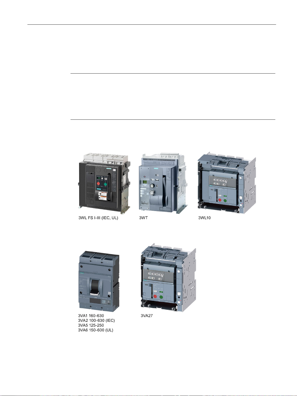
2.2 Compatible Siemens SENTRON switching devices
2.2 Compatible Siemens SENTRON switching devices
The ATC6500 permits the transfer between two supply sources using the following Siemens
products.
r must be implemented to switch between circuit breakers.
Connection (Page 83). For
formation about testing, please refer to chapter Accessories for switching devices
age 101).
Compatible Siemens products
● Air circuit breakers (ACB)
● Molded case circuit breakers (MCCB)
3KC ATC6500 transfer control device
Manual, 05/2019, L1V30538268002A-01
17

General information
2.2 Compatible Siemens SENTRON switching devices
3KC ATC6500 transfer control device
18 Manual, 05/2019, L1V30538268002A-01

3
The following chapter contains information on:
● Transfer control
● Controlling the switching devices
● Voltage measurement
3.1 Transfer control
Fundamental information on the topic of transfer control is provided below.
Transfer with switch disconnectors / transfer switching equipment with motor operator
Switching devices with motor operator are required for this application. These can make
short-circuit currents and conduct them to a limited extent (1 sec. current), but cannot break
them.
Transfer with circuit breakers with motor operator
The transfer in this case is performed by means of motor-driven circuit breakers. These can
make and conduct short-circuit currents, and also break them in the event of an overload.
The ATC6500 functions as transfer switching equipment in connection with two Siemens
3VA molded case circuit breakers with motor operators, and in connection with two 3WL or
3WT air circuit breakers.
3.1.1 Network/network application
In the network/network application the load is normally connected to the main supply source
and is switched to the secondary supply source if an anomaly occurs in the main supply or if
an external signal is issued. By means of various setting options (interlock time, etc.) the
transfer behavior can be defined on a customer-specific basis.
You can find more information on this in the chapter Parameterization (Page 155).
3KC ATC6500 transfer control device
Manual, 05/2019, L1V30538268002A-01
19

Applications
3.1 Transfer control
3.1.2 Network/generator application
For the network/generator application the load is normally connected to the main source
(Source 1). Following a deviation in the voltage or frequency, and after the defined delay
time, a start signal is sent to the generator (Source 2). If the generator supplies the desired
voltage, the load is transferred to the secondary source (generator) until the main source
supplies the desired supply quality.
The load is then transferred back to the main source and the generator is kept in operation
without load to allow it to cool (duration can be set by user). The ATC6500 sends a start /
stop command to the generator through a relay output and can receive digital signals from
the generator indicating its status (generator ready, OK to accept load, etc.) through
programmable inputs.
An automatic generator test can be programmed, i.e. the generator can be started at set
times to check its correct operation, even if the network is within the thresholds.
This is done by setting the execution interval, starting time, days of the week on which the
test is to be carried out, duration, etc. More information on the various setting options can be
found in chapter Parameterization (Page 155).
3.1.3 Generator/generator application
In this case two generators are controlled, each with a start-stop relay and feedback signals,
if available. In this application a rotation between generators can be programmed, i.e. the
load can be switched from one to the other at regular intervals, with the purpose of sharing
out the generator work equally.
It is also possible to set the time of day when rotation is to occur, so that the load supply is
cut off at a specified time. In case of a problem in either generator, the load is always
transferred to the one in standby mode.
3.1.4 Load management with the ATC6500
Apart from applications with two switching devices, the ATC6500 can additionally control one
tie breaker. The ATC6500 has five predefined application settings.
The application must be selected in accordance with with the requirement in menu P02
under the parameter P02.01 (see chapter P02 – General (Page 162)).
The following applications can be implemented:
3KC ATC6500 transfer control device
20 Manual, 05/2019, L1V30538268002A-01

Applications
Source 1 (SRC1)
Source 2 (SRC2)
Breaker 1 (BRK 1)
Breaker 2 (BRK 2)
0 0 Open
Open
0 1 Open
Closed
1 1 Closed
Open
0 = Infeed source not available
1 = Infeed source available
Note
In this case Source 1 is regarded
modifying the source priority.
3.1 Transfer control
3.1.4.1 Application A: 2S – 0T
SRC1 (kVA) = SRC2 (kVA)
In this application two motor-driven circuit breakers with one outgoing load are used.
See also
The ATC6500 switches to one of the two sources, depending on the setting.
The states can be obtained from the table:
as the main source. The transfer can be influenced by
Parameterization (Page 155)
Transfer (Page 227)
3KC ATC6500 transfer control device
Manual, 05/2019, L1V30538268002A-01
21

Applications
Source 1 (SRC1)
Source 2 (SRC2)
Breaker 1 (BRK 1)
Breaker 2 (BRK 2)
Tie breaker (TB)
0 0 Open
Open
Open
0 1 Open
Closed
Open
1 1 Closed
Open
Closed
0 = Infeed source not available
1 = Infeed source available
Note
In this case Source 1 is regarded as the main source. The transfer can be influenced by
modifying the source priori
3.1 Transfer control
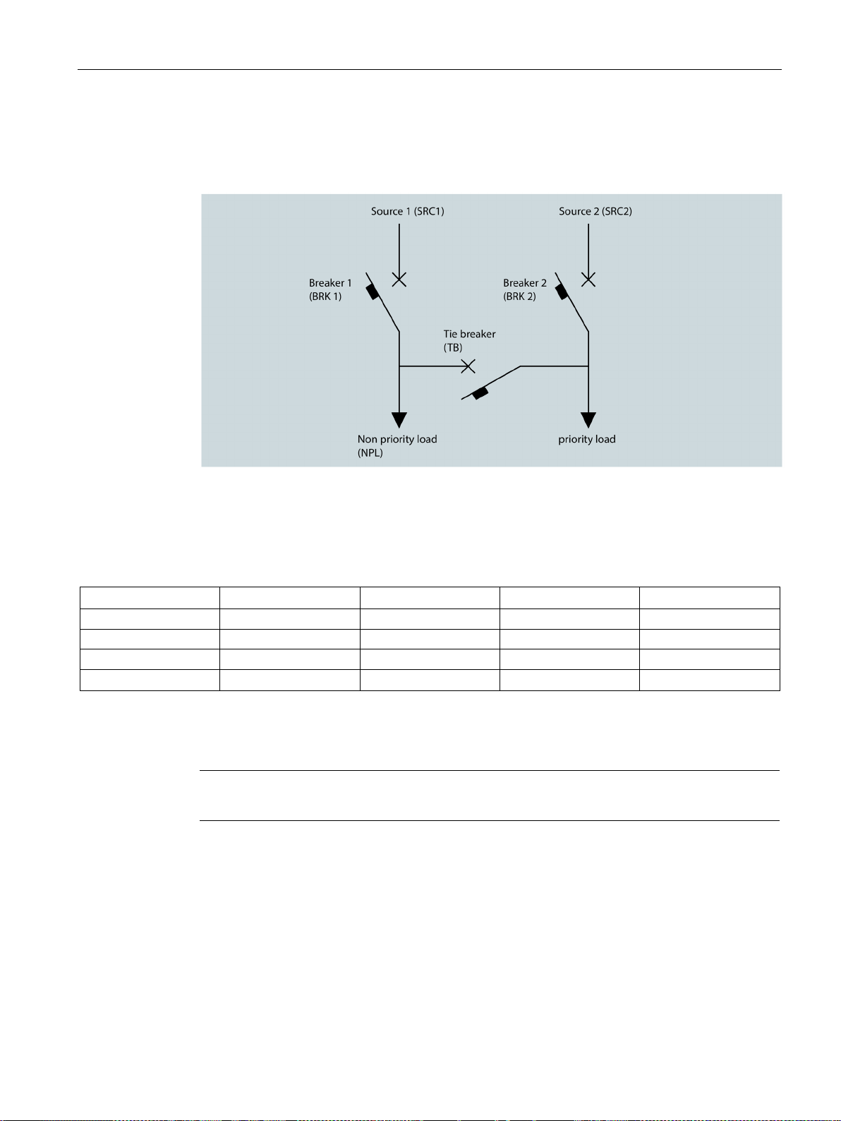
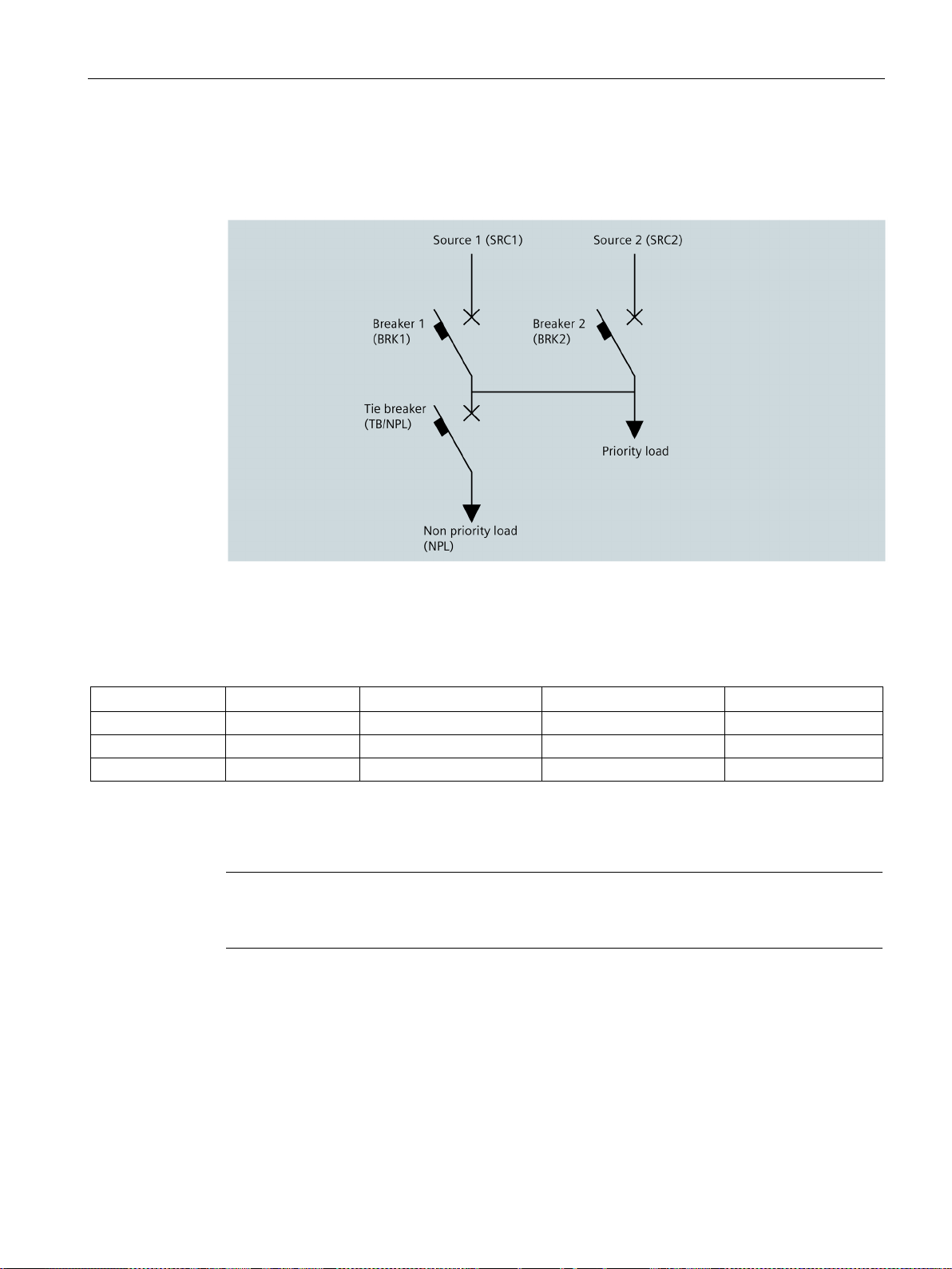
3.1.4.2 Application B: 2S - 1T - PL
SRC1 (kVA) > SRC2 (kVA)
In this application three motor-driven circuit breakers are used. A distinction is made
between prioritized load and non-prioritized load (NPL).
See also
On failure of the prioritized sources (in this case, Source 1), only the prioritized load is
supplied by the secondary source (in this case, Source 2). In normal circumstances (Source
1 available) both sources are supplied by the main network.
The states can be obtained from the table:
ty.
Parameterization (Page 155)
Transfer (Page 227)
3KC ATC6500 transfer control device
22 Manual, 05/2019, L1V30538268002A-01
Applications
Source 1 (SRC1)
Source 2 (SRC2)
Breaker 1 (BRK 1)
Breaker 2 (BRK 2)
Tie breaker (TB)
0 0 Open
Open
Open
0 1 Open
Closed
Closed
1 0 Closed
Open
Closed
Closed
Closed
0 = Infeed source not available
1 = Infeed source available
Note
In this case the priority of the sources is unimport
3.1 Transfer control
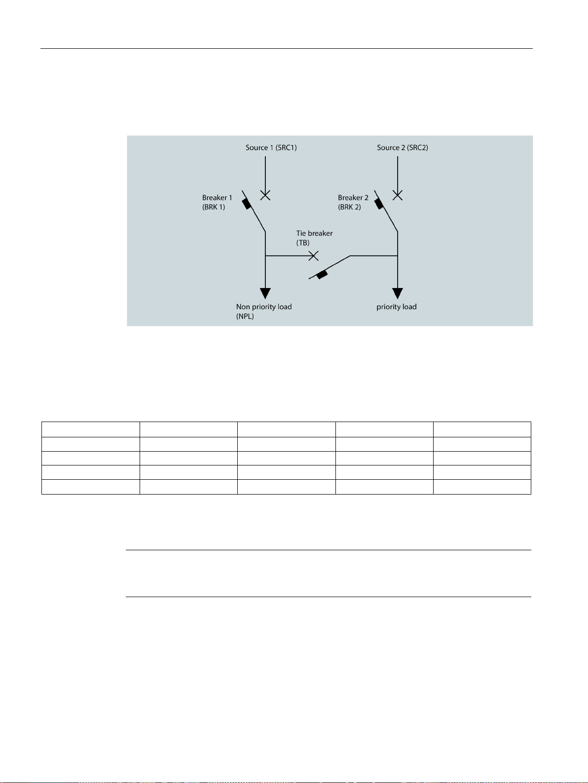
3.1.4.3 Application C: 2S – 1T – SI
SRC1 (kVA) = SRC2 (kVA)
In this application three motor-driven circuit breakers are used. A distinction is made
between prioritized load and non-prioritized load (NPL). In this case, both loads are supplied
by one source each in normal circumstances (both sources available). If one source fails, the
prioritized and non-prioritized loads are supplied by the source that remains available.
The states can be obtained from the table:
1 1
See also
Parameterization (Page 155)
Transfer (Page 227)
Open
ant.
3KC ATC6500 transfer control device
Manual, 05/2019, L1V30538268002A-01
23
Applications
Source 1 (SRC1)
Source 2 (SRC2)
Breaker 1 (BRK 1)
Breaker 2 (BRK 2)
Tie breaker (TB)
0 0 Open
Open
Open
0 1 Open
Closed
Open
1 0 Closed
Open
Closed
Closed
Closed
0 = Infeed source not available
1 = Infeed source available
Note
In this case Source 1 is regarded as t
modifying the source priority.
3.1 Transfer control
3.1.4.4 Application D: 2S - 1T - AI
SRC1 (kVA) > SRC2 (kVA)
In this application three motor-driven circuit breakers are used. A distinction is made
between prioritized load and non-prioritized load (NPL).
In this application, both loads are supplied by one source each in normal circumstances
(both sources available). If Source 2 fails, both the prioritized load and the non-prioritized
load are supplied by Source 1. Source 2, on the other hand, only supplies the prioritized
load.
1 1
See also
Open
he main source. The transfer can be influenced by
Parameterization (Page 155)
Transfer (Page 227)
3KC ATC6500 transfer control device
24 Manual, 05/2019, L1V30538268002A-01
Applications
Source 1 (SRC1)
Source 2 (SRC2)
Breaker 1 (BRK 1)
Breaker 2 (BRK 2)
Tie breaker (TB/NPL)
0 0 Open
Open
Open
0 1 Open
Closed
Open
1 1 Closed
Open
Closed
0 = Infeed source not available
1 = Infeed source available
Note
In th
modifying the source priority.
3.1 Transfer control
3.1.4.5 Application O: 2S - NPL
SRC1 (kVA) > SRC2 (kVA)
See also
In this application three motor-driven circuit breakers are used. A distinction is made
between prioritized load and non-prioritized load (NPL). In this application, on failure of the
prioritized sources (in this case, Source 1), only the prioritized load is supplied by the
secondary source (in this case, Source 2). In normal circumstances (Source 1 available)
both sources are supplied by the main network.
is case Source 1 is regarded as the main source. The transfer can be influenced by
3KC ATC6500 transfer control device
Manual, 05/2019, L1V30538268002A-01
Parameterization (Page 155)
Transfer (Page 227)
25

Applications
3.2 Controlling the switching devices
3.2 Controlling the switching devices
The ATC6500 can control various devices for automatic transfer switching. How the control
of the switching devices can be implemented is shown below.
● Depending on the type of transfer device used, the appropriate circuit diagram shall be
used (see chapter Connection (Page 83)), as well as the programmable inputs/outputs on
the ATC6500 (see chapter Inputs and outputs of the ATC6500 (Page 144)).
● Programmable outputs are set by default for the use of circuit breakers (see chapter P13
- Digital outputs (Page 180))
● The application is to be selected in accordance with the requirement (see chapter Load
management with the ATC6500 (Page 20) and chapter Parameterization (Page 155))
● The device status inputs (e.g. status of circuit breakers) shall be wired according to the
circuit diagram, so as to ensure reliable system operation.
● Nonetheless, it is possible to manage without wiring the status inputs. This enables the
programmable inputs to be used for other functions. In this case the device behaves as if
the status feedback messages were received immediately.
● If the device status inputs are not used, then after power-on the ATC6500 sends an
"open" command, in order to put the switching devices in a defined status.
● If the device status inputs are used, then after power-on the ATC6500 does not send any
commands to the breaker. The corresponding switching devices are not controlled until
anomalies occur in the network.
● Internal control relays are neither electrically nor mechanically interlocked.
3KC ATC6500 transfer control device
26 Manual, 05/2019, L1V30538268002A-01

Applications
3.2 Controlling the switching devices
3.2.1 Controlling motor-driven circuit breakers
The control of motor-driven circuit breakers requires four outputs (open and close commands
for Source 1 and Source 2) and two inputs for circuit breaker status feedback for the
application with two circuit breakers. If a further circuit breaker is used (see chapter Load
management (Page 20)) an additional 2 outputs (the commands Open / Close for the tie
breaker) and one input for the status of the tie breaker must be wired. For the control of the
tie breaker additional outputs can be attached by means of expansion modules.
Additional optional inputs may be required for alarm signals and TRIP.
● Open and close commands can be output as a continuous signal or a pulse. For the
continuous signal, the pulse is applied continuously until the circuit breaker has reached
the required position.
● The signal type (continuous signal or pulse) for the two circuit breakers can be selected
by setting the appropriate parameter under P08.01 in menu P08 to "Brk. Pul." or "Brk.
Con.". The control of the tie breaker is defined by parameter P02.22 in menu P02. For
this too, the signal setting can be adapted accordingly.
● The status for TRIP is ignored for a 15-second window every time an open command is
sent to the circuit breakers. This prevents a false alarm from being triggered if the circuit
breakers temporarily signal the TRIP status through their alarm switches while opening.
This has no effect on the function of the circuit breaker.
● If feedback inputs (circuit breaker status) are used and the circuit breaker does not close,
a second attempt is made before triggering an alarm.
See also
Connection (Page 83)
Parameters (Page 160)
3.2.2 Controlling remotely operated transfer switching equipment
The control of remotely operated transfer switching equipment (single motor operator) is
similar to the control of motor-driven circuit breakers, however it requires only three outputs
(close Source 1, open both sources, close Source 2) and two inputs for the status of the
transfer switching equipment.
● The command mode (continuous signal or pulse) can be selected by setting the
appropriate parameter under P08.01 in menu P08 to "Chg. Pul." or "Chg. Con.".
See also
Connection (Page 83)
Parameters (Page 160)
3KC ATC6500 transfer control device
Manual, 05/2019, L1V30538268002A-01
27

Applications
Note
Procedure for voltage measurement
The fundamentals of the procedure for adjusting the voltage measur
below. The exact parameters can be found in chapter
3.3 Voltage measurement
3.2.3 Controlling contactors
If contactors are used, two outputs (Close 1 and Close 2) and two status inputs are required.
If an additional contactor is used as a tie breaker, an additional output (close tie breaker) and
a status input are required.
● In this case the appropriate parameter under P08.01 in menu P08 must be set to
"Contactors" in the command mode. In addition, the parameter P02.22 in menu P02 must
be set to "Contactors".
See also
Connection (Page 83)
Parameters (Page 160)
3.3 Voltage measurement
This section illustrates how a voltage measurement is achieved for the ATC6500.
ement are explained
Parameters (Page 160).
All parameters and settings can be adjusted by the user in the menus P02 General
(Page 162), P06 Source Lines (Page 168
), P08 Switch (Page 171)and P09 Source Line
CHK (Page 174).
3KC ATC6500 transfer control device
28 Manual, 05/2019, L1V30538268002A-01
 Loading...