

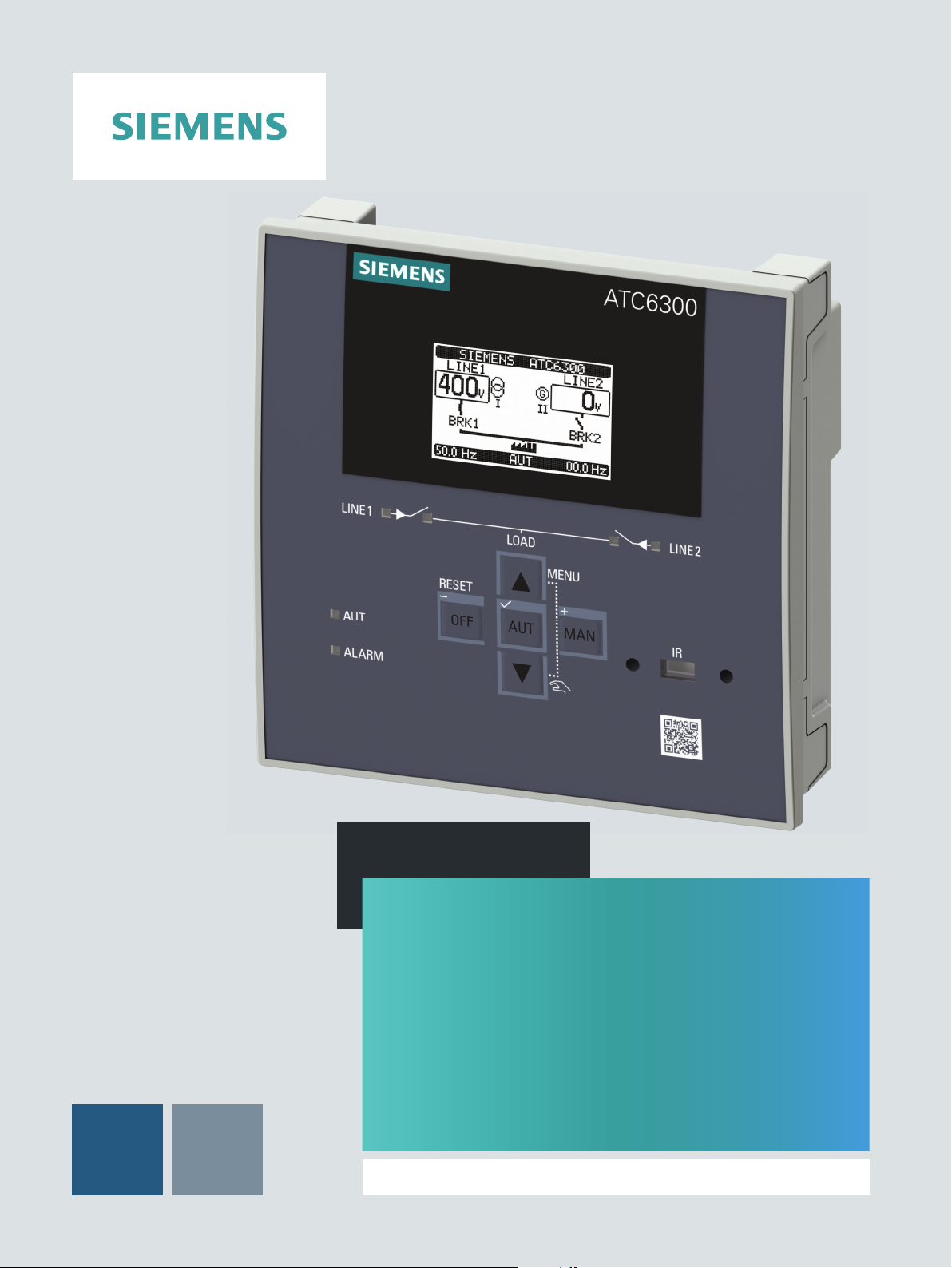
Siemens SENTRON ATC6300 User Manual
Manual
SENTRON
Monitoring Devices
3KC ATC6300
Transfer Control Device
03/2018Edition
siemens.com/3KC


___________________
___________________
___________________
___________________
___________________
___________________
___________________
___________________
___________________
___________________
___________________
___________________
___________________
___________________
___________________
SENTRON
Transfer switching equipment and
load transfer switches
3KC ATC6300 transfer control
device
Manual
03/2018
L1V30535632002A
Introduction
1
General information
2
Applications
3
Product description
4
Functions
5
Installation
6
Connection
7
Operation
8
Parameterization
9
Commissioning
10
MODBUS communication
11
Accessories
12
Technical specifications
13
Dimension drawings
14
List of abbreviations
A
-01

Siemens AG
Division Energy Management
Postfach 32 20
91050 ERLANGEN
GERMANY
Document order number: 3ZW1012-0KC00-4AC1
Ⓟ
Copyright © Siemens AG 2018.
All rights reserved
Legal information
Warning notice system
DANGER
indicates that death or severe personal injury will result if proper precautions are not taken.
WARNING
indicates that death or severe personal injury may result if proper precautions are not taken.
CAUTION
indicates that minor personal injury can result if proper precautions are not taken.
NOTICE
indicates that property damage can result if proper precautions are not taken.
Qualified Personnel
personnel qualified
Proper use of Siemens products
WARNING
Siemens products may only be used for the applications described in the catalog and in the relevant technical
ambient conditions must be complied with. The information in the relevant documentation must be observed.
Trademarks
Disclaimer of Liability
This manual contains notices you have to observe in order to ensure your personal safety, as well as to prevent
damage to property. The notices referring to your personal safety are highlighted in the manual by a safety alert
symbol, notices referring only to property damage have no safety alert symbol. These notices shown below are
graded according to the degree of danger.
If more than one degree of danger is present, the warning notice representing the highest degree of danger will
be used. A notice warning of injury to persons with a safety alert symbol may also include a warning relating to
property damage.
The product/system described in this documentation may be operated only by
task in accordance with the relevant documentation, in particular its warning notices and safety instructions.
Qualified personnel are those who, based on their training and experience, are capable of identifying risks and
avoiding potential hazards when working with these products/systems.
Note the following:
documentation. If products and components from other manufacturers are used, these must be recommended
or approved by Siemens. Proper transport, storage, installation, assembly, commissioning, operation and
maintenance are required to ensure that the products operate safely and without any problems. The permissible
All names identified by ® are registered trademarks of Siemens AG. The remaining trademarks in this publication
may be trademarks whose use by third parties for their own purposes could violate the rights of the owner.
We have reviewed the contents of this publication to ensure consistency with the hardware and software
described. Since variance cannot be precluded entirely, we cannot guarantee full consistency. However, the
information in this publication is reviewed regularly and any necessary corrections are included in subsequent
editions.
for the specific
03/2018 Subject to change

Table of contents
1 Introduction ............................................................................................................................................. 7
2 General information ................................................................................................................................ 9
3 Applications .......................................................................................................................................... 13
4 Product description ............................................................................................................................... 19
5 Functions .............................................................................................................................................. 35
1.1 About this documentation ......................................................................................................... 7
1.2 Product-specific information ..................................................................................................... 8
1.2.1 Certification ............................................................................................................................... 8
1.2.2 Reference documents ............................................................................................................... 8
1.2.3 Technical Support ..................................................................................................................... 8
2.1 Properties of the ATC6300 transfer control device ................................................................... 9
2.2 Compatible Siemens SENTRON switching devices ............................................................... 11
3.1 Transfer control ....................................................................................................................... 13
3.1.1 Network/network application ................................................................................................... 13
3.1.2 Network/generator application ................................................................................................ 14
3.1.3 Generator/generator application ............................................................................................. 14
3.2 Controlling the switching devices ............................................................................................ 15
3.2.1 Controlling circuit breakers with motor operator ..................................................................... 15
3.2.2 Controlling remotely operated transfer switching equipment.................................................. 16
3.2.3 Controlling contactors ............................................................................................................. 16
3.3 Voltage control ........................................................................................................................ 16
4.1 Product description ................................................................................................................. 19
4.2 Menu navigation ...................................................................................................................... 22
4.3 Description of the main menu ................................................................................................. 22
4.4 Navigation through the main menu ......................................................................................... 24
4.5 Display pages of the ATC6300 ............................................................................................... 24
4.5.1 Description of the display pages ............................................................................................. 24
4.5.2 Scrolling through the display pages ........................................................................................ 34
5.1 Basic functions ........................................................................................................................ 35
5.1.1 Setting the real-time clock ...................................................................................................... 35
5.1.2 Password protection ............................................................................................................... 36
5.1.2.1 Password protection against physical access ........................................................................ 36
5.1.2.2 Password protection against remote access (remote password) ........................................... 37
5.1.2.3 Entering the password via user interface................................................................................ 37
5.1.3 Keypad lock ............................................................................................................................ 39
5.1.3.1 Activation of the keypad lock by means of a programmable input ......................................... 39
5.1.3.2 Activation of the keypad lock by means of a key combination on the operator panel ............ 40
5.1.4 Expandability by modules ....................................................................................................... 41
3KC ATC6300 transfer control device
Manual, 03/2018, L1V30535632002A-01
3

Table of contents
6 Installation ............................................................................................................................................ 63
7 Connection ........................................................................................................................................... 65
5.1.4.1 Enabling additional resources ................................................................................................ 42
5.1.4.2 Inserting an expansion module .............................................................................................. 43
5.1.4.3 Behavior of the ATC6300 after inserting a module ................................................................ 44
5.1.5 Communication COMx ........................................................................................................... 45
5.1.6 Alarms .................................................................................................................................... 46
5.1.6.1 Properties of the alarms ......................................................................................................... 47
5.1.6.2 Alarm description ................................................................................................................... 48
5.1.6.3 Alarm table ............................................................................................................................. 49
5.1.6.4 User alarms ............................................................................................................................ 50
5.1.7 Automatic test ........................................................................................................................ 51
5.1.7.1 Enabling the automatic test .................................................................................................... 51
5.1.7.2 Stopping the automatic test ................................................................................................... 51
5.1.8 Simulation of priority line failure ............................................................................................. 52
5.1.9 Command menu..................................................................................................................... 53
5.1.9.1 Executing a command ........................................................................................................... 53
5.1.9.2 Table of commands ............................................................................................................... 55
5.1.10 Event log ................................................................................................................................ 56
5.2 Extended functions ................................................................................................................ 57
5.2.1 Remote variables REMx ........................................................................................................ 57
5.2.2 User limit LIMx ....................................................................................................................... 57
5.2.3 Counter CNTx ........................................................................................................................ 61
6.1 Dimensions for the door cutout .............................................................................................. 63
6.2 Installation of the ATC6300 .................................................................................................... 63
7.1 General connection drawings ................................................................................................ 66
7.1.1 Connection of circuit breakers with motor operator ............................................................... 66
7.1.2 Connection of remotely operated transfer control devices .................................................... 68
7.1.3 Connection of contactors ....................................................................................................... 69
7.2 Connection of the power supply............................................................................................. 70
7.2.1 Implementation of the dual power supply by means of dual network connection
3KC9625-1 (for IEC applications only) .................................................................................. 71
7.2.2 Implementation of the dual power supply by means of a voltage monitoring relay ............... 73
7.2.3 Implementation of the dual power supply by means of an electromechanical relay ............. 73
7.2.4 Implementation of the dual power supply by means of a UPS .............................................. 74
7.2.5 Recommended implementation for gen-set application (with power supply by means of
a DC source) .......................................................................................................................... 74
7.2.6 Recommended implementation for gen-set application (without power supply by
means of a DC source) .......................................................................................................... 75
7.3 Connection of Siemens SENTRON switching devices .......................................................... 76
7.3.1 Accessories for switching devices ......................................................................................... 76
7.3.2 Accessories for mechanical interlocking ................................................................................ 77
7.3.3 Technical specifications of the Siemens SENTRON switching devices in accordance
with IEC 60947-6-1 (IEC only) ............................................................................................... 82
7.3.3.1 Typical operating times of the Siemens SENTRON switching devices in accordance
with IEC 60947-6-1 (IEC only) ............................................................................................... 86
7.3.4 Connection of 3VA molded case circuit breakers .................................................................. 89
7.3.4.1 Connection of 3VA molded case circuit breakers - MO320 (IEC, UL) ................................... 89
3KC ATC6300 transfer control device
4 Manual, 03/2018, L1V30535632002A-01

Table of contents
8 Operation ............................................................................................................................................ 101
9 Parameterization ................................................................................................................................. 115
10 Commissioning ................................................................................................................................... 145
7.3.4.2 Connection of 3VA molded case circuit breakers - SEO520 (IEC) ........................................ 90
7.3.5 Connection of 3VL molded case circuit breakers ................................................................... 92
7.3.5.1 Connection of molded case circuit breakers 3VL 160X - 3VL 800 MO (IEC) ......................... 92
7.3.5.2 Connection of molded case circuit breakers 3VL 1250-1600 MO (IEC), 3VL 1200-1600
MO (UL), 3VL SEO (UL, IEC) ................................................................................................. 94
7.3.6 Connection of 3WL air circuit breakers, FS I - III (IEC, UL) .................................................... 96
7.3.7 Connection of 3WT air circuit breakers (IEC) ......................................................................... 98
7.3.8 Connection of the 3KC3 / 3KC4 transfer switching equipment .............................................. 99
8.1 Operating modes of the ATC6300 ........................................................................................ 101
8.1.1 Setting the operating mode ................................................................................................... 101
8.1.2 OFF mode (OFF) .................................................................................................................. 102
8.1.3 Manual mode (MAN) ............................................................................................................. 102
8.1.4 Automatic mode (AUT) ......................................................................................................... 105
8.2 Designation and description of the inputs ............................................................................. 106
8.2.1 Voltage measuring inputs ..................................................................................................... 106
8.2.2 Digital inputs INPx ................................................................................................................. 107
8.2.3 Addressing the expansion modules with digital inputs ......................................................... 107
8.2.4 Table of functions of the digital inputs .................................................................................. 108
8.3 Designation and description of the outputs .......................................................................... 110
8.3.1 Digital outputs OUTx ............................................................................................................. 110
8.3.2 Table of functions of the digital outputs ................................................................................ 112
9.1 Parameterization via the user interface ................................................................................ 115
9.1.1 Changing the parameters ..................................................................................................... 117
9.2 Parameterization via the powerconfig software .................................................................... 118
9.2.1 Procedure for parameterization via powerconfig .................................................................. 118
9.2.2 Parameterization via the front interface ................................................................................ 119
9.2.2.1 Attaching the front interface .................................................................................................. 119
9.2.3 Parameterization via the expansion modules for communication ........................................ 120
9.3 Parameters ........................................................................................................................... 120
9.3.1 P01 - Settings ....................................................................................................................... 121
9.3.2 P02 - General ........................................................................................................................ 122
9.3.3 P03 - Password ..................................................................................................................... 123
9.3.4 P04 - Battery ......................................................................................................................... 124
9.3.5 P05 - Changeover ................................................................................................................. 125
9.3.6 P06 - Parameter Line 1 ......................................................................................................... 130
9.3.7 P07 - Parameter Line 2 ......................................................................................................... 132
9.3.8 P08 - Communication ........................................................................................................... 134
9.3.9 P09 - Automatic test .............................................................................................................. 136
9.3.10 P10 - Digital inputs ................................................................................................................ 137
9.3.11 P11 - Digital outputs .............................................................................................................. 138
9.3.12 P12 - Miscellaneous .............................................................................................................. 139
9.3.13 P13 - Limit thresholds ........................................................................................................... 140
9.3.14 P14 - Counters ......................................................................................................................
142
9.3.15 P15 - User alarms ................................................................................................................. 143
3KC ATC6300 transfer control device
Manual, 03/2018, L1V30535632002A-01
5

Table of contents
11 MODBUS communication .................................................................................................................... 147
12 Accessories ......................................................................................................................................... 175
13 Technical specifications ....................................................................................................................... 195
14 Dimension drawings ............................................................................................................................. 199
A List of abbreviations ............................................................................................................................. 201
Index ................................................................................................................................................... 203
11.1 General information on MODBUS........................................................................................ 147
11.2 MODBUS RTU protocol ....................................................................................................... 148
11.3 MODBUS ASCII protocol ..................................................................................................... 149
11.4 MODBUS functions .............................................................................................................. 151
11.5 Password entry by means of MODBUS ............................................................................... 156
11.6 Data library ........................................................................................................................... 157
11.6.1 Measured values (use with MODBUS function 03 and 04) ................................................. 157
11.6.2 Status bits (use with MODBUS function 03 and 04) ............................................................ 159
11.6.3 Commands (use with MODBUS function 06) ...................................................................... 164
11.6.4 Status of the ATC (use with MODBUS function 03 and 04) ................................................ 166
11.6.5 Real-time clock (use with MODBUS function 04 and 06) .................................................... 167
11.7 Reading the event log .......................................................................................................... 167
11.8 Reading parameters by means of MODBUS ....................................................................... 170
11.9 Changing parameters by means of MODBUS ..................................................................... 170
12.1 Expansion modules .............................................................................................................. 175
12.1.1 Expansion module 4DI - 3KC9000-8TL60 ........................................................................... 176
12.1.1.1 Technical specifications ....................................................................................................... 178
12.1.2 Expansion module 4DO - 3KC9000-8TL61 ......................................................................... 180
12.1.2.1 Technical specifications ....................................................................................................... 181
12.1.3 Expansion module 2DI 2DO - 3KC9000-8TL62 ................................................................... 182
12.1.3.1 Technical specifications ....................................................................................................... 184
12.1.4 Expansion module 2DO - 3KC9000-8TL63 ......................................................................... 185
12.1.4.1 Technical specifications ....................................................................................................... 186
12.1.5 Expansion module 2DI 2DO - 3KC9000-8TL64 ................................................................... 188
12.1.5.1 Expansion module 2DI 2DO - 3KC9000-8TL64 ................................................................... 188
12.1.5.2 Technical specifications ....................................................................................................... 189
12.1.6 Expansion module RS485 - 3KC9000-8TL74 ...................................................................... 190
12.1.6.1 Technical specifications ....................................................................................................... 191
12.1.7 Expansion module Ethernet - 3KC9000-8TL75 ................................................................... 192
12.1.7.1 Technical specifications ....................................................................................................... 192
12.2 Cover frame - 3KC9000-8TL68 ............................................................................................ 193
12.3 USB front interface - 3KC9000-8TL73 ................................................................................. 194
A.1 List of abbreviations ............................................................................................................. 201
3KC ATC6300 transfer control device
6 Manual, 03/2018, L1V30535632002A-01

1
1.1
About this documentation
Purpose of this manual
Scope of validity of this document
Knowledge required
Target readers
The information contained in this manual enables you to install, operate and use the
3KC ATC6300 transfer control device.
The manual contains information on:
● Product specifications
● Installation
● Operation
● Configuration
● Commissioning
● Application
This manual is a reference manual for technical information that users will need for
configuration and operation.
To understand this manual, you will need to have a general knowledge of low-voltage
controls and power distribution.
The information contained in this manual is provided for the benefit of:
● Users
● Electrically skilled persons
● Switchgear manufacturers
● Maintenance personnel
3KC ATC6300 transfer control device
Manual, 03/2018, L1V30535632002A-01
7
Introduction
1.2
Product-specific information
1.2.1
Certification
1.2.2
Reference documents
Further documents and information
Title
Article number
Link
page
(http://www.siemens.com/switching-devices)
51947)
51948)
51949)
_02.pdf)
1.2.3
Technical Support
1.2 Product-specific information
You will find further information in the following documents:
Siemens switching devices home
Operating instructions 3KC ATC6300
transfer control device
Operating instructions
ATC6 DI/DO expansion modules
Operating instructions
ATC6 Ethernet expansion modules
Operating instructions
ATC6 RS485 expansion modules
MODBUS over Serial Line Specification and Implementation Guide
You can find further support on the Internet at:
Siemens switching devices
3ZW1012-0KC00-1A
A0
3ZW1012-0KC00-2A
A0
3ZW1012-0KC00-3A
A0
3ZW1012-0KC00-4A
A0
MODBUS over Serial Line Specification and Implementa-
3KC ATC6300 transfer control device
https://support.industry.siemens.com/cs/ww/en/view/1097
(
51946)
ATC6 DI/DO expansion modules
(
https://support.industry.siemens.com/cs/ww/en/view/1097
ATC6 Ethernet expansion modules
https://support.industry.siemens.com/cs/ww/en/view/1097
(
ATC6 RS485 expansion modules
https://support.industry.siemens.com/cs/ww/en/view/1097
(
tion Guide
(http://www.modbus.org/docs/Modbus_over_serial_line_V1
Technical Support (http://www.siemens.com/lowvoltage/technical-support
3KC ATC6300 transfer control device
8 Manual, 03/2018, L1V30535632002A-01
)

2
2.1
Properties of the ATC6300 transfer control device
Features
Technical functions
The ATC6300 transfer control device, in combination with Siemens circuit breakers with
motor operators (ACB, MCCB) or remotely operated transfer switching equipment (RTSE),
enables a transfer between a main and an alternative power source. The stability of the
power supply is analyzed by means of voltage taps upstream of the switching devices. User
limit thresholds (voltage, frequency, phase sequence) function as boundary conditions for
analyzing the quality of the power supply. If a threshold is undershot or exceeded for a
specific defined time, the ATC6300 transfer control device initiates a transfer to an
alternative power source. Thanks to the ATC6300 transfer control device, in combination
with Siemens circuit breakers with motor operators and transfer switching equipment (3VA,
3VL, 3WL, 3WT, 3KC3, 3KC4 - see chapter Compatible Siemens SENTRON switching
devices (Page 11)), a user-defined source transfer can be performed in accordance with IEC
60947-6-1.
The interaction of the ATC6300 with the switching devices has been exhaustively tested, but
does not absolve plant operators from their own responsibility. The functionality, comparable
with the ATSE, is provided by the assembly of RTSE with a controller.
The key features of the ATC6300 transfer control device are:
● Backlit LCD (128 px x 80 px) for displaying measurements, events and alarms in five
● Expandable with a maximum of two additional expansion modules with digital inputs and
● 3KC9000-8TL73 USB front interface for setting parameters on the front panel. It is not
● Auxiliary voltage supply is possible by means of taps from the supply sources (110-240 V
● Measurement of three-phase networks with or without neutral conductor, of two-phase
● Control of circuit breakers with motor operator, remote transfer switching equipment or
languages (German, English, French, Spanish, Italian)
outputs, and by means of communications interfaces (RS485, Ethernet)
necessary to open the control cabinet.
AC 50/60 Hz) or by means of a separate DC source (12-24 V DC).
networks, and of single-phase networks.
contactors.
● Suitable for network/network, network/generator or generator/generator applications.
● 6 freely programmable digital inputs and 7 programmable relay outputs fitted to the
3KC ATC6300 transfer control device
Manual, 03/2018, L1V30535632002A-01
device.
9

General information
Metering functions
Area of application
2.1 Properties of the ATC6300 transfer control device
The ATC6300 permits voltage measurement not only between L-L, but also between N-L.
The following parameters are measured by the ATC6300:
● Phase sequence and phase failure
● Minimum and maximum voltage
● Voltage unbalance
● Minimum and maximum frequency
The ATC6300 transfer control device can be used in conjunction with Siemens switching
devices, e.g. in the following industrial areas in which a continuous power supply needs to be
ensured.
● Industry
– Production lines in continuous operation
– Engine rooms
– Auxiliary facilities in essentially important thermal power stations
– Pumps
– Cooling systems
– Fans
3KC ATC6300 transfer control device
10 Manual, 03/2018, L1V30535632002A-01
General information
2.2
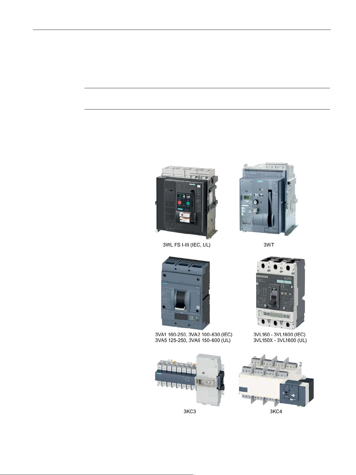
Compatible Siemens SENTRON switching devices
Note
A motor operator must be implemented to transfer between circuit breakers.
Compatible Siemens products
Air circuit breakers (ACB)
Molded case circuit
breakers (MCCB)
Remotely operated transfer switching equipment
(RTSE)
2.2 Compatible Siemens SENTRON switching devices
The ATC6300 permits the transfer between two supply sources using the following Siemens
products.
Precise connection diagrams can be obtained from chapter Connection (Page 65). For
further information about testing, please refer to chapter Accessories for switching devices
(Page 76).
3KC ATC6300 transfer control device
Manual, 03/2018, L1V30535632002A-01
11


3
3.1
Transfer control
Class PC:
Class CB:
3.1.1
Network/network application
The following chapter contains information on:
● Transfer control
● Controlling the switching devices
● Voltage control
Fundamental information on the topic of transfer control is provided below.
In accordance with IEC 60947-6-1 we differentiate between two classes of transfer switching
equipment:
Motorized switching devices are required for this application. These can make short-circuit
currents and conduct them to a limited extent (1 sec. current), but cannot break them. In
connection with the remotely operated Siemens 3KC3 or 3KC4 transfer switching equipment,
a user-defined transfer can be realized according to class PC.
The transfer in this case is performed by means of circuit breakers with motor operators.
These can make and conduct short-circuit currents, and also break them in the event of an
overload. The ATC6300 functions as class CB transfer switching equipment in connection
with two Siemens 3VA or 3VL molded case circuit breakers with motor operators, and in
connection with two 3WL or 3WT air circuit breakers.
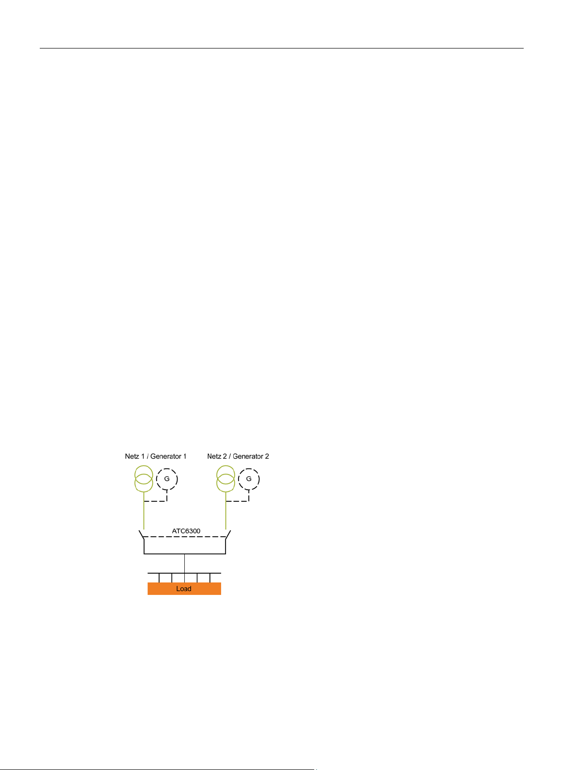
In the network/network application the load is normally connected to the main supply source
and is switched to the secondary supply source if an anomaly occurs in the main supply or if
an external signal is issued. By means of various setting options (interlock time, etc.) the
transfer behavior can be defined on a customer-specific basis.
You can find more information on this in the chapter Parameterization (Page 115).
3KC ATC6300 transfer control device
Manual, 03/2018, L1V30535632002A-01
13
Applications
3.1.2
Network/generator application
3.1.3
Generator/generator application
3.1 Transfer control
For the network/generator application the load is normally connected to the main source
(Line 1). Following a deviation in the voltage or frequency, and after the defined delay time, a
start signal is sent to the generator (Line 2). If the generator supplies the desired voltage, the
load is transferred to the secondary source (generator) until the main source supplies the
desired supply quality.
The load is then transferred back to the main source and the generator is kept in operation
without load to allow it to cool (duration can be set by user). The ATC6300 sends a start /
stop command to the generator through a relay output and can receive digital signals from
the generator indicating its status (generator ready, OK to accept load, etc.) through
programmable inputs.
An automatic generator test can be programmed, i.e. the generator can be started at set
times to check its correct operation, even if the network is within the thresholds.
This is done by setting the execution interval, starting time, days of the week on which the
test is to be carried out, duration, etc. More information on the various setting options can be
found in chapter Parameterization (Page 115).
In this case two generators are controlled, each with a start-stop relay and feedback signals,
if available. In this application a rotation between generators can be programmed, i.e. the
load can be switched from one to the other at regular intervals, with the purpose of sharing
out the generator work equally. It is also possible to set the time of day when rotation is to
occur, so that the load supply is cut off at a specified time. In case of a problem in either
generator, the load is always transferred to the one in standby mode.
The following simplified diagram illustrates the possible applications:
3KC ATC6300 transfer control device
14 Manual, 03/2018, L1V30535632002A-01

Applications
3.2
Controlling the switching devices
3.2.1
Controlling circuit breakers with motor operator
3.2 Controlling the switching devices
The ATC6300 can control various devices for automatic transfer switching.
How the control of the switching devices can be implemented is shown below.
● Depending on the type of transfer device used, the appropriate wiring diagram shall be
used (see chapter Connection (Page 65)), as well as the programmable inputs/outputs on
the ATC6300 (see chapter Description and designation of the outputs (Page 110)).
● Programmable outputs are set by default for the use of circuit breakers (see chapter
Description and designation of the outputs (Page 110))
● The device status inputs (e.g. status of circuit breakers) shall be wired according to the
circuit diagram, so as to ensure reliable system operation.
● Nonetheless, it is possible to manage without wiring the status inputs. This enables the
programmable inputs to be used for other functions. In this case the device behaves as if
the status feedback messages were received immediately.
● If the device status inputs are not used, then after power-on the ATC6300 sends an
"open" command, in order to put the switching devices in a defined status.
● If the device status inputs are used, then after power-on the ATC6300 does not send any
commands to the switching device. The corresponding switching devices are not
controlled until anomalies occur in the network.
● Internal control relays are neither electrically nor mechanically interlocked.
The control of circuit breakers with motor operator requires 4 outputs (open and close
commands for Line 1 and Line 2) and 2 inputs for circuit breaker status feedback, plus any
additional optional inputs for alarm signaling and TRIP, as well as optional outputs for
controlling undervoltage releases.
● Open and close commands can be output as a continuous signal or a pulse. For the
continuous signal, the pulse is applied continuously until the circuit breaker has reached
the required position.
● The command mode (continuous signal or pulse) can be selected by setting the
appropriate parameter under P05.07 in menu P05 to "Chg. Pul." or "Chg. Con."
● The TRIP status is ignored for a 15-second window every time an open command is sent
to the circuit breakers. This prevents a false alarm from being triggered if the circuit
breakers temporarily send a TRIP signal through their alarm switches while opening. This
has no effect on the function of the circuit breaker.
● If feedback inputs (circuit breaker status) are used and the circuit breaker does not close,
a second attempt is made before triggering an alarm.
Precise circuit diagrams as well as the parameters to be set can be found in chapter
Connection (Page 65) or in chapter Parameterization (Page 115).
3KC ATC6300 transfer control device
Manual, 03/2018, L1V30535632002A-01
15

Applications
3.2.2
Controlling remotely operated transfer switching equipment
3.2.3
Controlling contactors
3.3
Voltage control
Note
Procedure for voltage measurement
The fundamentals of the procedure for adjusting the voltage measurement are explained
below.
The exact parameters can be found in chapter
3.3 Voltage control
The control of remotely operated transfer switching equipment (single motor operator) is
similar to the control of circuit breakers with motor operator, however it requires only three
outputs (close Line 1, open both lines, close Line 2) and two inputs for the status of the
transfer switching equipment.
● The command mode (continuous signal or pulse) can be selected by setting the
appropriate parameter under P05.07 in menu P05 to "Chg. Pul." or "Chg. Con."
Precise circuit diagrams as well as the parameters to be set can be found in chapter
Connection (Page 65) or in chapter Parameterization (Page 115).
If two contactors are used, two outputs (CL.1 and CL.2) and two status inputs are required.
● In this case the appropriate parameter under P05.07 in menu P05 must be set to
"Contactors" in the command mode.
Precise circuit diagrams as well as the parameters to be set can be found in chapter
Connection (Page 65) or in chapter Parameterization (Page 115).
This section illustrates how a voltage measurement is achieved for the ATC6300.
Parameterization (Page 115).
All parameters and settings can be adjusted by the user in the menus P02 (General), P05
(Changeover), P06 (Parameter Line 1) and P07 (Parameter Line 2).
● The general system settings can be adjusted in Menu P02, including the rated voltage
and frequency. These are used as a reference for setting the percentage thresholds.
● A voltage ratio (VT) can be set if a voltage is applied to the measurement inputs of the
device which is higher or lower that the set rated voltage. In this case the display and
setting of limit thresholds are also performed on the actual variables in relation to the
system.
● The device can be adjusted for the voltage measurement of three-phase networks with or
without neutral conductor, two-phase or single-phase networks (P02.06).
3KC ATC6300 transfer control device
16 Manual, 03/2018, L1V30535632002A-01

Applications
Measurement
Description
Can be deactivated
Minimum voltage
One or more phases too low
No
the minimum voltage
Minimum frequency
Frequency too low
Yes
Maximum frequency
Frequency too high
Yes
Phase sequence
Checking the rotational direction of the phases
Yes
3.3 Voltage control
● In the case of three- or two-phase power supplies you can choose whether you want to
monitor the phase-to-phase voltage, the phase-to-neutral voltage, or both (P02.07). In
each case, the rated voltage set in P02.01 must be equal to the phase-to-phase voltage.
● The table below lists the measurements of the two lines. Some thresholds can also be
deactivated for triggering the transfer.
Maximum voltage One or more phases too high Yes
Phase failure Threshold value at which the device responds faster than when falling below
Voltage unbalance Voltage phases are not symmetrical to one another Yes
Yes
● Each measurement can be assigned a specific delay time. Measured anomalies (beyond
the threshold values) must be present for longer than the set delay times, before it can be
concluded that there is a line fault.
● When all the line parameters are restored within the specified thresholds, the delay time
must elapse before the restored line may be reconnected. This delay period is
determined by two independent parameters:
– P06.07 or P07.07 - delay time if the line is within the specified thresholds again (and
Line 2 or Line 1 is not available)
– P06.08 or P07.08 - delay time if the line is within the specified thresholds again (and
Line 2 or Line 1 is available)
● For the minimum and maximum voltages, two thresholds are defined in each case. One
for the point beyond which the voltage is no longer considered sufficient (e.g. P06.01,
threshold MIN trip voltage); and another which is closer to the rated voltage, defining the
point beyond which it is sufficient again (e.g. P06.02, threshold MIN reset).
The distance between these two thresholds determines the hysteresis. It is possible to
stipulate, for example, that the voltage may no longer be used when it falls below 80% of
the rated voltage, and that in order to be usable again, it must rise above 85%. This
defines a hysteresis of 5% (dead zone). The same principle is applied to the maximum
voltage.
● If the voltage is within the set thresholds when the device is switched on or reset, both
sources are considered to be in order (without considering the delay times), except when
the load is already supplied by a circuit breaker; then the delay times are taken into
consideration.
3KC ATC6300 transfer control device
Manual, 03/2018, L1V30535632002A-01
17

4
4.1
Product description
User interface
3KC ATC6300 transfer control device
Manual, 03/2018, L1V30535632002A-01
19

Product description
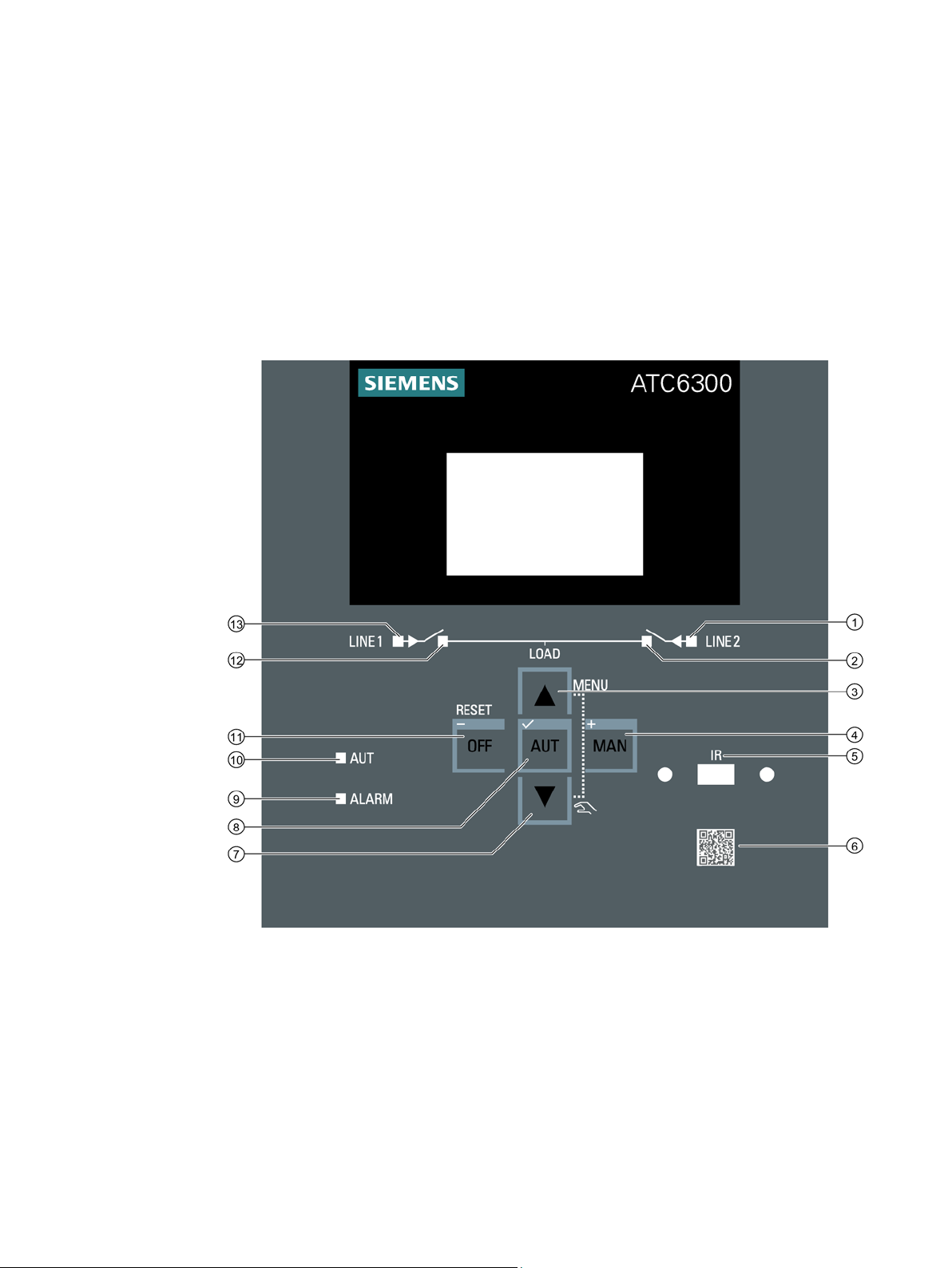
Status LEDs
No.
LED
LED ON
LED OFF
LED FLASHING
Line 2
available
(Page 132)
Line 2
closed
signal.
⑨
ALARM
this in chapter Alarms (Page 46).
AUT
mode.
⑫
Line 1
closed
Line 1
available
(Page 130)
4.1 Product description
The LEDs on the operator panel indicate the status of the device and/or the controlled
switching devices. The meaning of the various LEDs is shown in the following table:
①
②
Shows a steady green light if
the voltage and frequency are
within the defined thresholds.
Shows a steady orange light if
the switching device of Line 2
is closed.
Does not light up if the voltage
and/or frequency are outside the
defined thresholds.
Does not light if the switching
device of Line 2 is not closed.
Flashes green until the voltage is
back within the defined thresholds.
You can find more information in
chapter P07 - Line 2 parameters
Flashes orange if there is a discrepancy between the desired
status of the ATC6300 transfer
control device and the actual status detected from the feedback
⑩
⑬
— — Flashes red if an alarm is active.
You can find more information on
Shows a steady green light if
the ATC6300 transfer control
device is in the automatic
Shows a steady orange light if
the switching device of Line 1
is closed.
Shows a steady green light if
the voltage and frequency are
within the defined thresholds.
Does not light if the ATC6300
transfer control device is in the
manual or OFF mode.
Does not light if the switching
device of Line 1 is not closed.
Does not light up if the voltage
and frequency are outside the
defined thresholds.
—
Flashes orange if there is a discrepancy between the desired
status of the ATC6300 transfer
control device and the actual status detected from the feedback
signal.
Flashes green until the voltage is
back within the defined thresholds.
You can find more information in
chapter P06 - Line 1 parameters
3KC ATC6300 transfer control device
20 Manual, 03/2018, L1V30535632002A-01

Product description
Keys
No.
Key
Function
Key ▲
④
MAN / +
MAN / +
MAN / +
Key ▼
⑧
AUT / ✓
AUT / ✓
AUT / ✓
OFF / -
OFF / -
OFF / -
Interface
QR code
4.1 Product description
③
⑦
⑪
• Pressing this key switches between menu pages. Within the menus, it is used to switch between
the parameters.
• Pressing the
• If the
• Pressing this key switches between menu pages. Within the menus, it is used to switch between
the parameters.
• Pressing the
• Pressing the
• Pressing the
• If the
key is pressed within the individual menus, the parameters can be reduced.
key for at least 0.5 seconds selects the Manual operating mode.
key is pressed within the individual menus, the parameters can be increased.
key for more than 0.5 seconds selects the automatic mode.
key also confirms any settings that have been made.
key for more than 0.5 seconds selects the OFF mode.
Simultaneously pressing the ▲ and ▼ keys returns you to the main menu. You can find more
information in chapter
Menu navigation (Page 22).
A 3KC9000-8TL73 USB front interface can be attached to interface 5. This enables the
ATC6300 transfer control device to be parameterized from the front using powerconfig
(Version 3.10 or higher).
Further information on the 3KC9000-8TL73 USB front interface can be found in chapter
Parameterization via the front interface (Page 119) or in chapter USB front interface 3KC9000-8TL73 (Page 194)
The QR code 6 contains information that refers to the Industry Mall page of the ATC6300
transfer control device, where further information is available, e.g. operating instructions and
certificates.
3KC ATC6300 transfer control device
Manual, 03/2018, L1V30535632002A-01
21
Product description
4.2
Menu navigation
4.3
Description of the main menu
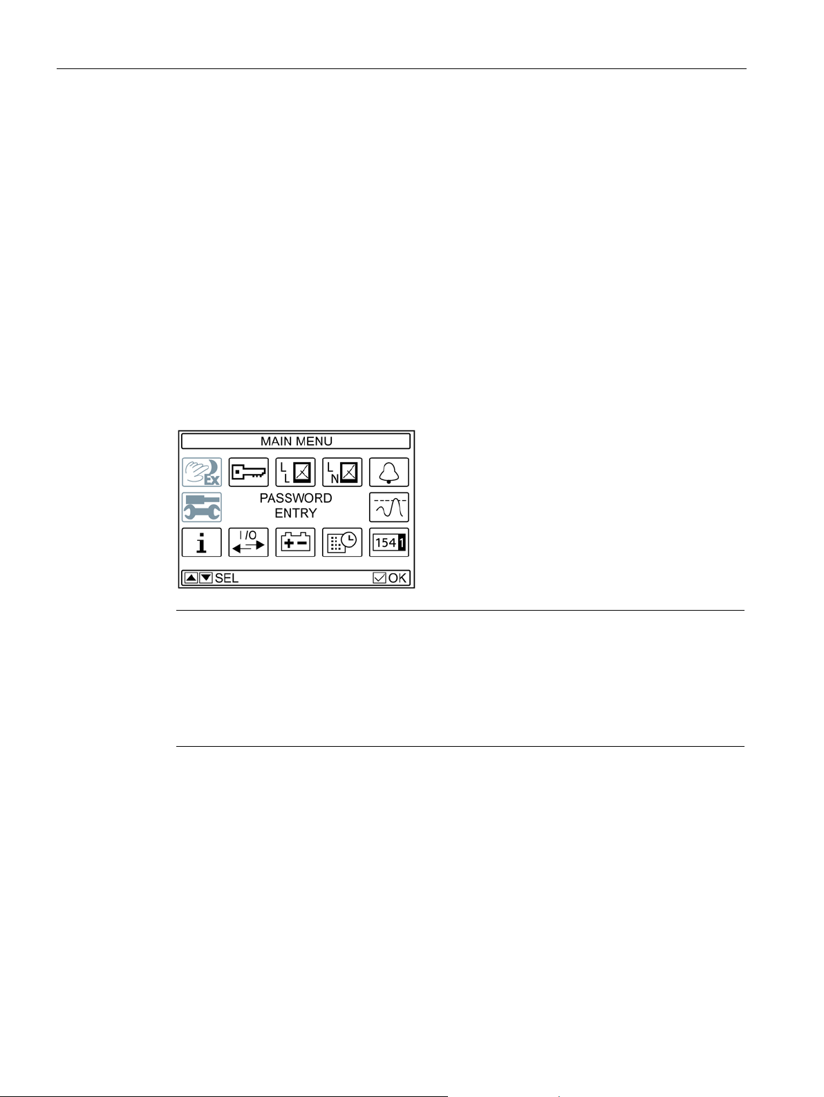
Procedure for opening the main menu
Structure of the main menu
Note
Password protection
Access to some menu items can be restricted by setting a password (see chapter
protection
the setup menu and Command menu). In addition, the message ACCESS LOCKED
indicates that a password is active. In its factory setting, the ATC contains a store
password. Therefore, these menu options can only be accessed after entering a password.
4.2 Menu navigation
The following section describes the front-mounted LCD. This display enables the device to
be parameterized (see chapter Parameterization (Page 115)).
In addition, measured values relating to voltage and frequency can be read from it.
Simultaneously pressing the ▲ and ▼ keys brings you to the main menu.
Password
(Page 36)). The unavailable icons are grayed out (shown here in the example of
d
3KC ATC6300 transfer control device
22 Manual, 03/2018, L1V30535632002A-01
Product description
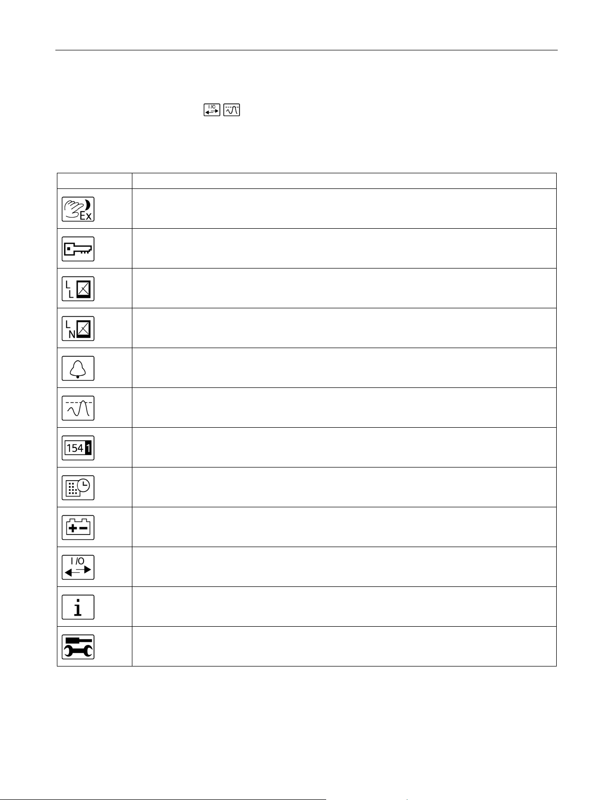
Description of the symbols
Symbol
Meaning
4.3 Description of the main menu
The symbols are used as shortcuts, with which the display pages of the
measurements can be retrieved faster.
They enable a jump to be made directly to the selected group of messages. From there, it is
possible to scroll forward or back as usual.
Access point to the command menu in which the authorized user can execute certain resetting and
restoring processes. Grayed out if the password has not been entered.
Input of the numerical code that allows access to the protected functions (see chapter Password protection (Page 36)).
Access point for displaying the real-time values of the voltage between L-L.
Access point for displaying the real-time values of the voltage between L-N.
Access point for displaying the active alarms.
Access point for displaying the set thresholds relating to the triggering of a transfer (see chapter Parameterization (Page 115)).
Access point to the statistical operating data of the control device.
Access point for displaying the stored events of the ATC6300.
Access point for displaying the real-time values of the battery. If no additional DC supply / battery is
used, this window is grayed out.
Access point that enables the operator to view the status of the inputs and outputs used.
Access point for displaying the system information via the ATC6300.
Access point to the setup menu. Grayed out if there is password protection and the password has not
yet been entered.
3KC ATC6300 transfer control device
Manual, 03/2018, L1V30535632002A-01
23
Product description
4.4
Navigation through the main menu
4.5
Display pages of the ATC6300
4.5.1
Description of the display pages
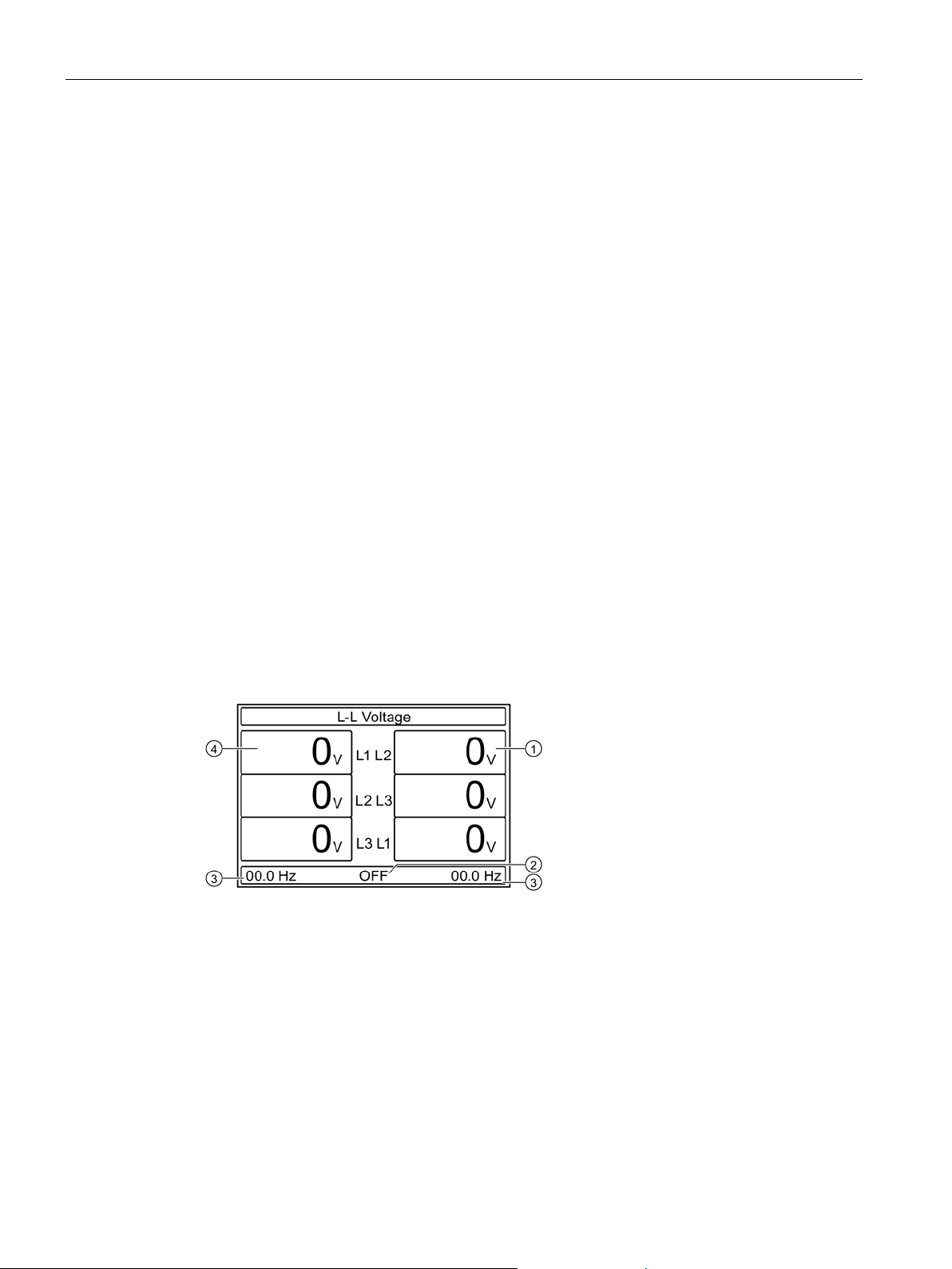
L-L Voltage
①
Real-time voltage L2 from Line 2
②
Operating mode
③
Frequency (Line 1 / Line 2)
④
Real-time voltage L1 from Line 1
4.4 Navigation through the main menu
Press ▲ or ▼ to scroll through the main menu functions in a clockwise / counter-clockwise
direction.
Alternatively, you can also scroll clockwise / counter-clockwise through the options using the
+ / - keys .
The selected symbol is highlighted and the description of the function is shown in the center
of the display .
The selected function can then be activated by pressing the ✓ key.
Some of the display pages listed below may possibly not be available if the function has
been deactivated. Likewise, additional display pages can be displayed if supplementary
functions are activated, e.g. limit thresholds. Some of the following display pages can only be
viewed via the main menu; you can scroll freely between the remaining pages.
The following display pages are available on the ATC6300.
3KC ATC6300 transfer control device
24 Manual, 03/2018, L1V30535632002A-01
Product description
L-N Voltage
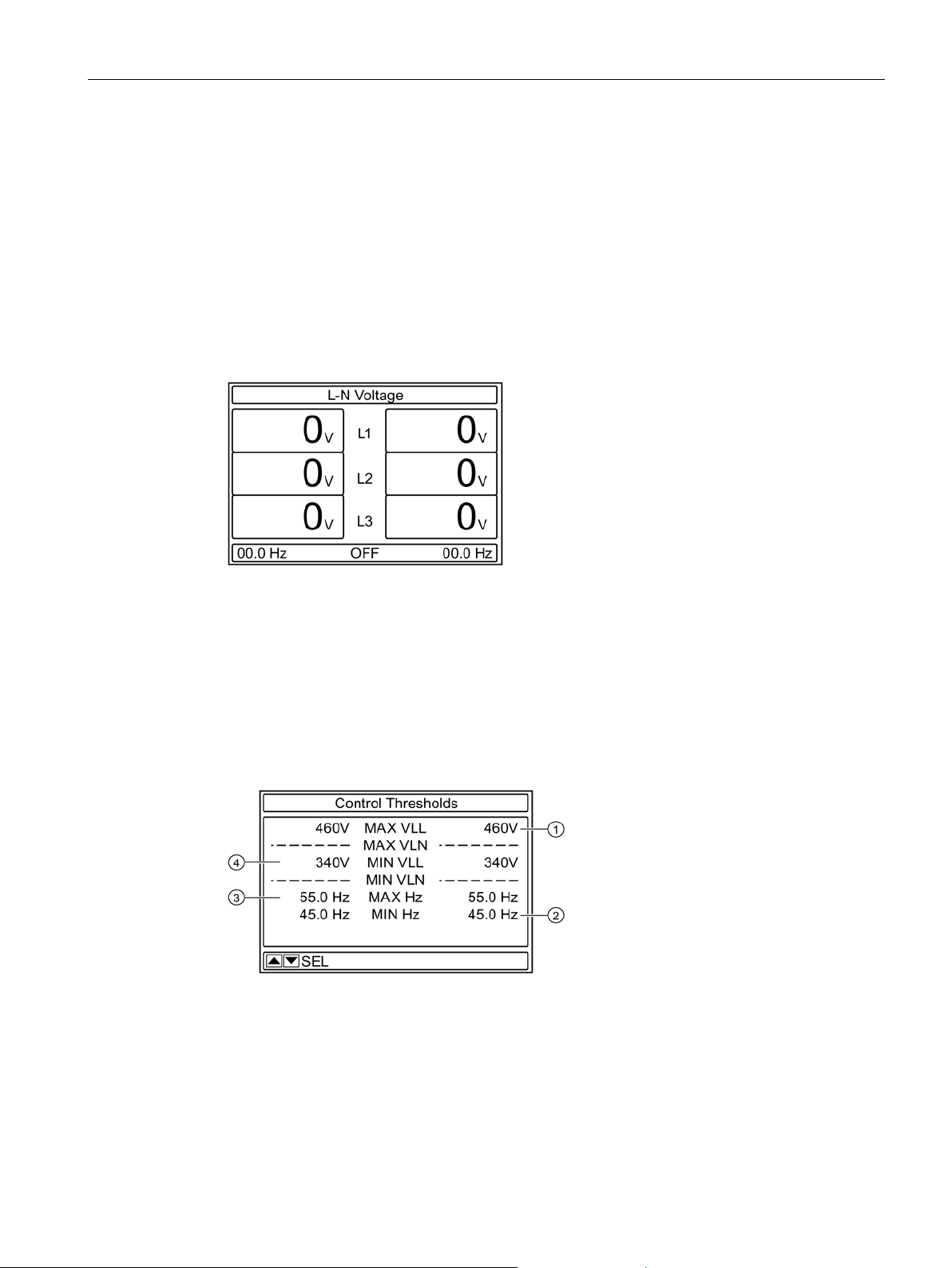
Control Thresholds
①
Maximum control threshold for Voltage (L-L) Line 2
②
Minimum control threshold for Frequency Line 2
③
Maximum control threshold for Frequency Line 1
④
Minimum control threshold for Voltage (L-L) Line 1
4.5 Display pages of the ATC6300
The submenu L-L Voltage shows the voltage between the phases.
The menu shows
● the voltages currently being measured
● the frequency of both lines currently being measured
● the current operating mode
This view is not available in single-phase supplies.
The submenu L-N Voltage shows the voltage between the phase and the neutral conductor.
The menu shows
● the voltages currently being measured
● the frequency of both lines currently being measured
● the current operating mode
The Control Thresholds submenu shows the maximum and minimum threshold values for
triggering the transfer.
3KC ATC6300 transfer control device
Manual, 03/2018, L1V30535632002A-01
25
Product description
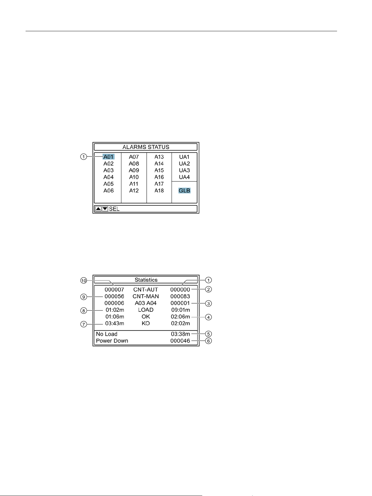
Alarms status
①
Active alarm
Statistics
①
Line 2
②
Counter of the switching operations in the automatic mode for Line 2
③
Alarm counter A04
④
Time during which the line is within the defined thresholds
⑤
Elapsed time in which the load has zero current
⑥
Counter of the deactivation processes
⑦
Time during which the line was outside the defined thresholds
⑧
Time in which the power supply was maintained by Line 1
⑨
Counter of the switching operations in the manual mode for Line 1
⑩
Line 1
4.5 Display pages of the ATC6300
It shows
● the threshold values of the voltage between L-L and between L-N (if set)
● the threshold values of the minimum and maximum frequency
If a threshold value is exceeded/undershot, it is shown with a black background, which
means that it is possible to check in real time in the Control Thresholds menu which
parameter of the voltage supply is causing problems.
The Alarms Status submenu lists all possible alarms of the ATC6300. If an alarm is active
the corresponding alarm has a black background.
The transfer behavior is shown in the Statistics submenu.
3KC ATC6300 transfer control device
26 Manual, 03/2018, L1V30535632002A-01
Product description
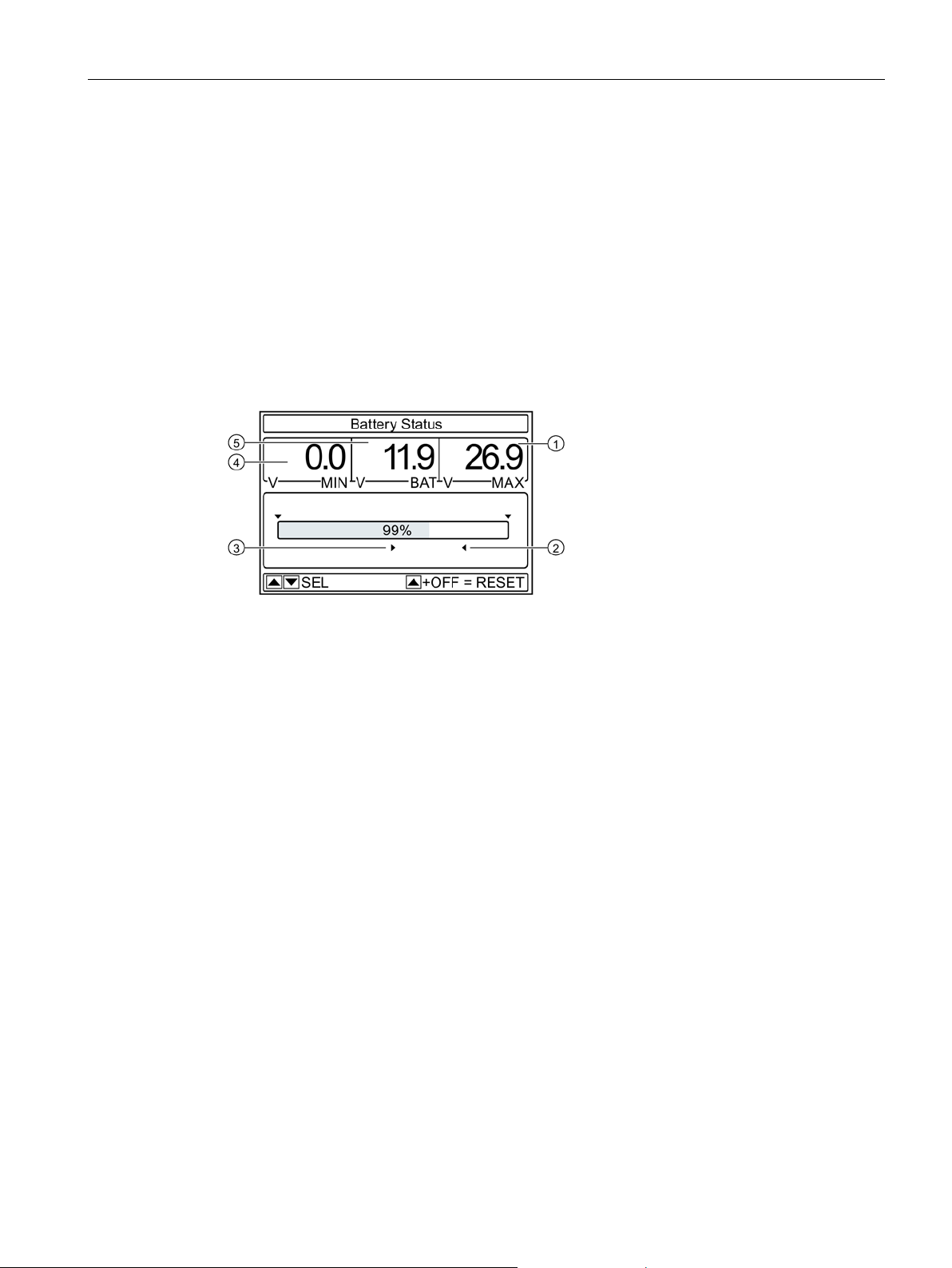
Battery Status
①
Measured maximum voltage of the DC battery power supply
②
Upper limit of the battery voltage
③
Lower limit of the battery voltage
④
Measured minimum voltage of the DC battery power supply
⑤
Current battery voltage
4.5 Display pages of the ATC6300
This shows:
● how often one of the two sources has been switched to the automatic and manual mode
● how often the alarms A03 and A04 (see chapter Alarms (Page 46)) have been active
● how long a supply has been maintained by the sources
● how long the sources have been within and and outside the defined thresholds
● how long the load has been without current
● how many shutdowns have been initiated
The Battery Status submenu indicates the current battery/DC supply voltage.
It shows:
● the lower and upper thresholds of the battery voltage
● the measured minimum and maximum values of the battery voltage
If no DC supply is used, then this menu is not visible.
3KC ATC6300 transfer control device
Manual, 03/2018, L1V30535632002A-01
27
Product description
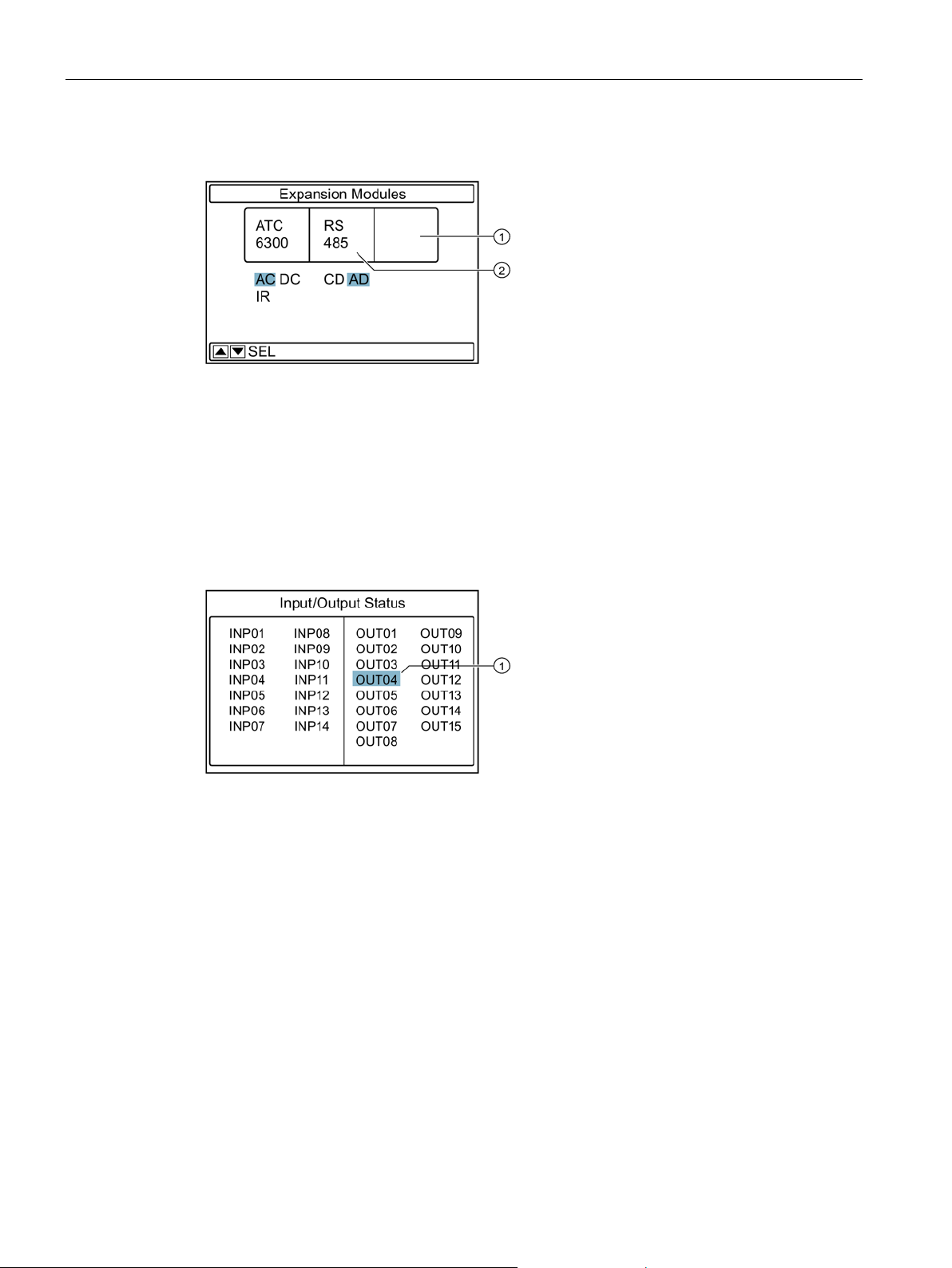
Expansion Modules
①
Slot 2
②
Slot 1
Input/Output Status
①
Output activated
4.5 Display pages of the ATC6300
The Expansion Modules submenu indicates whether additional modules (e.g. communication
modules) are plugged into the ATC6300, and which ones.
It shows how the ATC is being supplied (via AC or DC) and whether the USB front interface
has been inserted.
In the Input/Output Status submenu all digital inputs and outputs can be viewed. If an
input/output is active, the corresponding input or output is shown with a black background. In
addition to the permanently integrated inputs and outputs (6 inputs and 7 outputs) of the
ATC6300, the possible inputs and outputs of the expansion modules are also shown here.
3KC ATC6300 transfer control device
28 Manual, 03/2018, L1V30535632002A-01
 Loading...