

Siemens SENTRON 5TT7 System Manual


___________________
___________________
___________________
___________________
___________________
Monitoring Devices
SENTRON
GSM alarm module
System Manual
06/2014
2541304131
Introduction
1
Module
2
Further information
3
ESD guidelines
A
List of abbreviations
B
GSM alarm module
-01
DANGER
indicates that death or severe personal injury will result if proper precautions are not taken.
WARNING
indicates that death or severe personal injury may result if proper precautions are not taken.
CAUTION
indicates that minor personal injury can result if proper precautions are not taken.
NOTICE
indicates that property damage can result if proper precautions are not taken.
WARNING
Siemens products may only be used for the applications described in the catalog and in the relevant technical
Legal information
Warning notice system
This manual contains notices you have to observe in order to ensure your personal safety, as well as to prevent
damage to property. The notices referring to your personal safety are highlighted in the manual by a safety alert
symbol, notices referring only to property damage have no safety alert symbol. These notices shown below are
graded according to the degree of danger.
If more than one degree of danger is present, the warning notice representing the highest degree of danger will
be used. A notice warning of injury to persons with a safety alert symbol may also include a warning relating to
property damage.
Qualified Personnel
The product/system described in this documentation may be operated only by personnel qualified for the specific
task in accordance with the relevant documentation, in particular its warning notices and safety instructions.
Qualified personnel are those who, based on their training and experience, are capable of identifying risks and
avoiding potential hazards when working with these products/systems.
Proper use of Siemens products
Note the following:
documentation. If products and components from other manufacturers are used, these must be recommended
or approved by Siemens. Proper transport, storage, installation, assembly, commissioning, operation and
maintenance are required to ensure that the products operate safely and without any problems. The permissible
ambient conditions must be complied with. The information in the relevant documentation must be observed.
Trademarks
All names identified by ® are registered trademarks of Siemens AG. The remaining trademarks in this publication
may be trademarks whose use by third parties for their own purposes could violate the rights of the owner.
Disclaimer of Liability
We have reviewed the contents of this publication to ensure consistency with the hardware and software
described. Since variance cannot be precluded entirely, we cannot guarantee full consistency. However, the
information in this publication is reviewed regularly and any necessary corrections are included in subsequent
editions.
Siemens AG
Industry Sector
Postfach 48 48
90026 NÜRNBERG
GERMANY
Order number: 3ZW1012-5TT71-0AC0
Ⓟ 07/2014 Subject to change
Copyright © Siemens AG 2014.
All rights reserved

Table of contents
1 Introduction ................................................................................................................................................ 7
1.1 Overview ........................................................................................................................................ 7
1.2 Safety instructions .......................................................................................................................... 7
1.3 Software ......................................................................................................................................... 8
2 Module ....................................................................................................................................................... 9
2.1 Connecting ..................................................................................................................................... 9
2.2 Description of the LEDs ............................................................................................................... 12
2.3 Connecting to the GSM alarm module ......................................................................................... 13
2.4 Managing settings ........................................................................................................................ 14
2.4.1 Importing/exporting settings ......................................................................................................... 14
2.4.2 Data exchange ............................................................................................................................. 15
2.5 Configuring ................................................................................................................................... 16
2.5.1 Settings ........................................................................................................................................ 16
2.5.2 Phonebook ................................................................................................................................... 19
2.5.3 Diagnostics ................................................................................................................................... 20
2.5.4 I/O configuration and messaging ................................................................................................. 20
2.5.4.1 Universal inputs............................................................................................................................ 21
2.5.4.2 Digital outputs .............................................................................................................................. 28
2.5.4.3 Reading all I/O statuses ............................................................................................................... 33
2.5.4.4 Linking several GSM alarm modules ........................................................................................... 33
2.6 Advanced settings ........................................................................................................................ 34
2.6.1 Update .......................................................................................................................................... 35
2.6.2 Network ........................................................................................................................................ 37
2.6.3 SMTP ........................................................................................................................................... 39
2.6.4 Log ............................................................................................................................................... 41
2.6.5 Service option for the SIM ............................................................................................................ 44
2.6.6 COM port ...................................................................................................................................... 45
3 Further information .................................................................................................................................. 47
3.1 Troubleshooting ........................................................................................................................... 47
3.2 Overview of SMS commands ....................................................................................................... 49
3.3 Diagnostics commands ................................................................................................................ 50
3.4 Signal strength ............................................................................................................................. 51
3.5 Technical specifications ............................................................................................................... 52
A ESD guidelines ........................................................................................................................................ 55
A.1 Electrostatic sensitive devices (ESD) .......................................................................................... 55
GSM alarm module
System Manual, 06/2014, 2541304131-01
5

Table of contents
B List of abbreviations ................................................................................................................................. 57
B.1 Abbreviations .............................................................................................................................. 57
Glossary .................................................................................................................................................. 59
Index ........................................................................................................................................................ 61
GSM alarm module
6 System Manual, 06/2014, 2541304131-01

1
1.1 Overview
The GSM alarm module is a compact, distributed control and signaling system. All the inputs
and outputs (I/Os) of the module are monitored by SMS text messages and email, and are
controlled by SMS communication through the GSM network.
The module is configured by means of configuration software. Every input and output can be
modified by means of user-defined parameter names and messages. A selected group of
users can be chosen from the phonebook to configure and operate the module ("active
users"), or only to receive messages ("users").
GSM alarm module features:
● 4 digital outputs (DO), relay outputs, changeover contacts, 250 V/5 A
● 8 universal inputs (UI), which can be set by means of configuration software:
– Analog input (AI), 0 to 10 V
– Digital input (DI)
The module sends a previously defined message to selected persons with every defined
change of state (rising or falling flank in the case of digital inputs or reaching a level in the
case of analog inputs).
The outputs are switched whenever an active user sends a previously defined SMS to the
GSM alarm module.
For testing purposes, the GSM alarm module can send a text message (SMS) on a regular
basis, i.e. at a user-defined time. In the event of a power failure, the module still has enough
energy to send an SMS message to all active users to inform them of the power failure. It
also sends an SMS message once the power supply has been restored.
1.2 Safety instructions
● The GSM alarm module must NOT be used to monitor sensitive or time-critical
processes. A power supply interruption or a GSM network failure can prevent
uninterrupted monitoring.
● ESD precautions must be taken when opening the module.
● This module requires a GSM data connection. You can obtain information about the costs
from your GSM service provider.
GSM alarm module
System Manual, 06/2014, 2541304131-01
7

Introduction
1.3 Software
1.3 Software
Download the latest configuration software
http://support.automation.siemens.com/DE/view/de/53507447/130000 //
(
XmlEditor.InternalXmlClipboard:6a7e075e-5dfc-fdbd-9dfe-a555079bf9ab)from the Internet.
System requirements
The following are required for correct functioning:
● Windows XP (SP3), Vista, WIN 7, WIN 8
● Monitor with a minimum resolution of 1024 x 768 pixels
● 100 MB free hard disk capacity
● 256 MB RAM
● USB interface
Software installation
See also
Certain hardware drivers must be installed on your system for the program to function.
Therefore, make sure you have administrator rights during installation.
Run the GSM_Alarm_Module_setup.exe file to install the software. The Setup wizard guides
you through the installation procedure.
Update (Page 35)
GSM alarm module
8 System Manual, 06/2014, 2541304131-01
2
Note
ESD precautions must be taken when opening the module.
To avoid damaging the module, make sure you are not statically charged when opening it
and inserting the SIM card.
2.1 Connecting
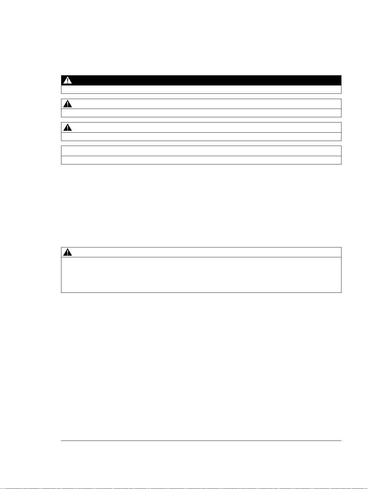
Inserting the SIM card
Place a SIM card in the SIM card holder to obtain access to the GSM network:
● Use a small flat screwdriver to raise the lid.
Figure 2-1 Opening the top lid
● Place the SIM card in the SIM card holder.
Figure 2-2 Inserting the SIM card in the GSM alarm module
● Then put the lid on again.
GSM alarm module
System Manual, 06/2014, 2541304131-01
9
Module
2.1 Connecting
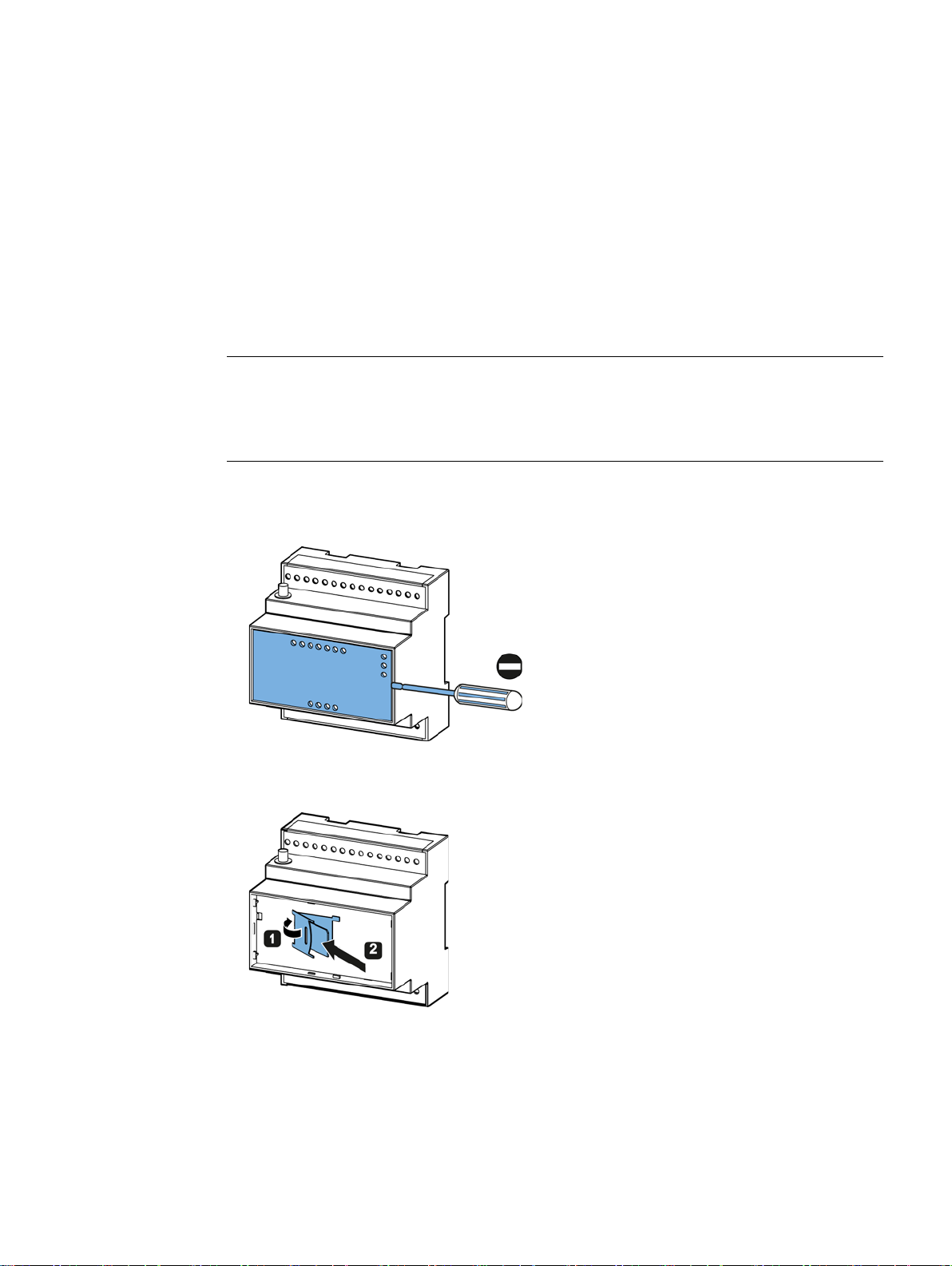
Connecting the antenna
Connect the antenna to the antenna terminal on the top of the module.
Figure 2-3 Screwing on the included GSM antenna
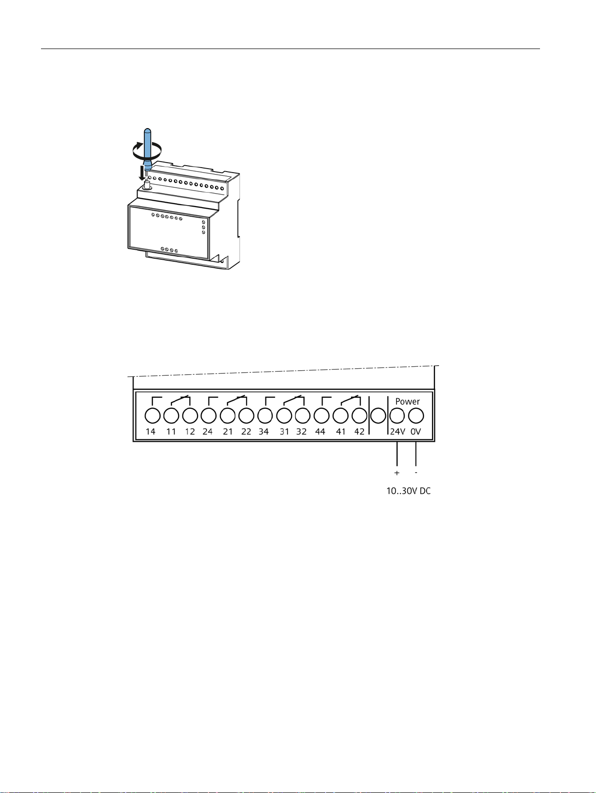
Connecting the power supply
Connect the 24 V and 0 V terminals to a 24 V DC power supply unit (recommended).
You can also use a 10 to 30 V DC power supply unit (power supply connection), however.
Figure 2-4 Connecting the power supply
GSM alarm module
10 System Manual, 06/2014, 2541304131-01

Module
Note
Install the configuration software first before you connect the module to the PC.
2.1 Connecting
Connecting to a PC
Connect a USB cable to the module's mini-USB socket and connect the other end to the
PC's USB interface.
Figure 2-5 Connecting the USB cable to the mini-USB terminal
GSM alarm module
System Manual, 06/2014, 2541304131-01
11

Module
Flashing
= module is starting up (takes about 90 seconds)
ON
= module is ready (flashing every 10 seconds)
OFF
= no supply voltage
Flashing green
= roaming in the GSM network
Green OFF
= no connection to the GSM network
ON
= module is currently active
2.2 Description of the LEDs
2.2 Description of the LEDs
Module status displays
After the operating voltage has been connected, the first LED lights up after about 10
seconds.
The 'Run' LED indicates functioning of the module:
The 'Com' LED indicates network activity by the module. This LED has a two-part structure.
If both parts light up green, everything is alright and the connection to the GSM network has
been established. If the left part is green and the right part is red, the connection to the GSM
network has been established, but the time has not yet been synchronized.
I/O displays
The 'Busy' LED indicates module activity:
The module restarts automatically after every data transfer between the PC and the module.
All UI LEDs light up during restarting.
● The LEDs pertaining to the universal inputs (UI) light up when:
– Set as a digital input: the input is active (status 1)
– Set as an analog input: a high or low threshold is reached
● For each of the digital outputs (DO), an LED lights up when the relay is activated.
GSM alarm module
12 System Manual, 06/2014, 2541304131-01

Module
Note
It takes the module roughly 90 seconds to start up completely. After the operating voltage
has been connected, the first LED lights up after about 10 seconds.
Note
The "Upload settings to module" function overwrites all values in the module with the
ones specified in the configuration software. Empty fields are also transferred to the
module.
2.3 Connecting to the GSM alarm module
2.3 Connecting to the GSM alarm module
Preferably connect the GSM alarm module to a 24 V DC power supply and then connect the
module to the USB interface of a PC using a USB cable. Wait until the module has started
up and then start the configuration software.
When the software is started, it searches through all COM interfaces of the PC for a
connected GSM alarm module. If a module is found, the software downloads the module's
data and asks whether you wish to load the module's settings in the configuration software.
● Yes: all set values are displayed in the configuration software and can be edited.
● No: the configuration software's fields are not filled.
If no module is found during starting, although a module is connected, click on the "Connect"
button on the top right of the window
or select "Connect to module" on the "Synchronize" tab.
The text 'Connected' appears in the bottom left corner if the module has been found.
GSM alarm module
System Manual, 06/2014, 2541304131-01
13

Module
2.4 Managing settings
2.4 Managing settings
2.4.1 Importing/exporting settings
The following button offers you diverse options for importing and exporting settings:
1. Import settings
Imports saved settings (*.ccf files) from the PC.
2. Export settings
Exports settings (*.ccf files) to the PC to be able to reuse them later for other GSM alarm
modules, for example.
3. Interface default settings
Restores the default settings.
4. Print settings
Prints the settings entered in the configuration software.
GSM alarm module
14 System Manual, 06/2014, 2541304131-01

Module
Note
When settings are uploaded into the module, all the current settings in the module are
overwritten. This is why you should first download and save the module's settings before
loading new settings into the module.
2.4 Managing settings
2.4.2 Data exchange
Click on the "Data exchange" button to exchange data with the module.
1. Upload settings to module
Loads the current values set in the configuration software to the module.
2. Download from module
Loads all the module's settings into the configuration software.
3. Reset module to default
Resets all the module's settings to the factory defaults.
4. Sync. date/time
The module's date and time are synchronized with the PC's system time.
5. Restart device
Due to the capacitor installed in the module, it is not possible to trigger a fast restart by
interrupting the operating voltage.
Click on this command to restart the device by the software.
6. Connect to module
The module is connected to the PC via the US connection.
GSM alarm module
System Manual, 06/2014, 2541304131-01
15

Module
Note
All settings defined in the configuration software must be actively loaded into the module.
2.5 Configuring
2.5 Configuring
2.5.1 Settings
Setting the language
You can choose the language via the "Edit" -> "Language" menu.
Basic settings
You define the module's basic functions on the 'Setting's tab:
● Module name
● SIM PIN No., which is the PIN number for access to the SIM card.
GSM alarm module
16 System Manual, 06/2014, 2541304131-01
Module
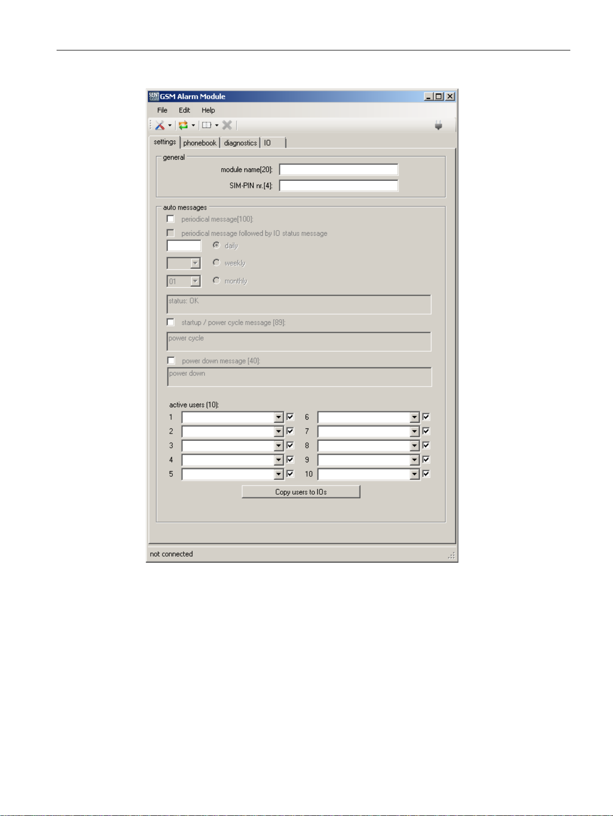
2.5 Configuring
Figure 2-6 "Settings" tab
GSM alarm module
System Manual, 06/2014, 2541304131-01
17

Module
Daily:
set the time (hh:mm)
Weekly:
set the day and the time (hh:mm)
Monthly:
set the day of the month (1 to 29) and the time (hh:mm)
Note
The module tries to send the SMS message to all active users, but only sending of the SMS
to the first 5 active users is guaranteed.
2.5 Configuring
Auto messages/periodical message
The GSM alarm module can send a message regularly, i.e. at user-defined times:
All active users receive this message.
The actual status of all I/Os can be added to the message ("periodical message followed by
IO status message").
Startup/power cycle message
Each time it is started, the GSM alarm module can send a message so that users are
informed about the fact that the operating voltage has been activated again.
Power down message
Active users
In the event of a power failure, the module still has enough energy to send an SMS message
to active users. The GSM alarm module registers a power failure whenever the voltage
drops below 8 V and switches on again at a voltage over 10 V.
Active users are those who have full access to the module and who receive automatic
messages. The order of notification is determined by the order of the chosen users (No. 1 to
10).
You can only choose active users from the phonebook.
Deactivate the checkbox next to the relevant active user if that user is to be permitted to
access the GSM alarm module, but is not to receive messages from the module.
When you click on the "Copy users to IOs" button, you copy the selected active users to all
I/O pages.
GSM alarm module
18 System Manual, 06/2014, 2541304131-01

Module
Note
Notification by email requires an Internet connection.
United Kingdom
+44
Germany
+49
France
+33
Netherlands
+31
Italy
+39
Spain
+34
Poland
+48
2.5 Configuring
2.5.2 Phonebook
The configuration software features a phonebook in which all contacts are listed
("Phonebook" tab).
All changes you make in the phonebook are saved automatically on completion.
You must add all users to the phonebook who are to have access to or information about the
module.
Adding contacts
To add a contact to the phonebook click on the next empty row and enter the person's name
and telephone number or their name and email address.
Note
The international prefix must be placed before the telephone number, e.g.
Deleting contacts
To delete a contact, click on one or more rows you wish to delete and then on the 'Delete'
button.
Importing/exporting the phonebook
You can import the phonebook from a file or you can export it to a file (cpf file).
1. Import phonebook
2.
Export phonebook
GSM alarm module
System Manual, 06/2014, 2541304131-01
19

Module
2.5 Configuring
2.5.3 Diagnostics
The 'Diagnostics' tab is filled out after connection with the module has been established.
The following information is displayed on the page:
● The GSM network in use or a connection error ("not registered")
● Signal strength as a percentage and signal quality
● The module's date and time
● The module's firmware version
● The module's IMEI number
● Error messages such as:
– SIM PIN code required
– SIM PUK code required
– No SIM card
– Date/time not set
– No user selected
– No connection to GSM network
You can update the 'Diagnostics' tab by clicking on the 'Diagnostic check' button.
Send the "status" SMS to the module to query the values by SMS.
Click on the 'Check data connection' button to check whether the module is able to establish
a GPRS (Internet) connection. You can find further information on setting up an Internet
connection in chapter "Network" (Page 37).
Signal strength
The signal strength information is determined in compliance with GSM network
specifications. You will find an overview in the appendix of this manual.
Send the "csq" SMS to the module to query the the signal strength and quality of the
connection by SMS.
2.5.4 I/O configuration and messaging
The module responds to read and write commands by SMS. Commands are preceded by an
r' for read or 'w' for write actions.
'
SMS commands can be written in both upper and lower case.
GSM alarm module
20 System Manual, 06/2014, 2541304131-01
 Loading...