

Siemens SENTRON 3VL630, SENTRON 3VL160, SENTRON 3VL400, SENTRON 3VL800, SENTRON 3VL1250 System Manual
...
SENTRON
Protection devices
3VL IEC molded case circuit breakers
System Manual
11/2013Edition
Answers for Infrastructure & Cities.


3VL IEC molded case circuit breakers
___________________
___________________
___________________
___________________
___________________
___________________
___________________
___________________
___________________
___________________
___________________
___________________
___________________
___________________
___________________
SENTRON
Protection devices
3VL IEC molded case circuit
breakers
System Manual
11/2013
110 0110
About this document
1
Product-specific information
2
Product description
3
Functions
4
Application planning
5
Installing/mounting
6
Connecting
7
Displays and operator
controls
8
Parameter assignment /
addressing
9
Service and maintenance
10
Technical data
11
Dimensional drawings
12
Circuit diagrams
13
Spare parts/accessories
14
Appendix
A
- 02 DS 03
Siemens AG
Industry Sector
Postfach 48 48
90026 NÜRNBERG
GERMANY
Order number: 3ZX1012-0VL10-0AC1
Ⓟ
Copyright © Siemens AG 2009.
All rights reserved
Legal information
Warning notice system
DANGER
indicates that death or severe personal injury will result if proper precautions are not taken.
WARNING
indicates that death or severe personal injury may result if proper precautions are not taken.
CAUTION
indicates that minor personal injury can result if proper precautions are not taken.
NOTICE
indicates that property damage can result if proper precautions are not taken.
Qualified Personnel
personnel qualified
Proper use of Siemens products
WARNING
Siemens products may only be used for the applications described in the catalog and in the relevant technical
ambient conditions must be complied with. The information in the relevant documentation must be observed.
Trademarks
Disclaimer of Liability
This manual contains notices you have to observe in order to ensure your personal safety, as well as to prevent
damage to property. The notices referring to your personal safety are highlighted in the manual by a safety alert
symbol, notices referring only to property damage have no safety alert symbol. These notices shown below are
graded according to the degree of danger.
If more than one degree of danger is present, the warning notice representing the highest degree of danger will
be used. A notice warning of injury to persons with a safety alert symbol may also include a warning relating to
property damage.
The product/system described in this documentation may be operated only by
task in accordance with the relevant documentation, in particular its warning notices and safety instructions.
Qualified personnel are those who, based on their training and experience, are capable of identifying risks and
avoiding potential hazards when working with these products/systems.
for the specific
Note the following:
documentation. If products and components from other manufacturers are used, these must be recommended
or approved by Siemens. Proper transport, storage, installation, assembly, commissioning, operation and
maintenance are required to ensure that the products operate safely and without any problems. The permissible
All names identified by ® are registered trademarks of Siemens AG. The remaining trademarks in this publication
may be trademarks whose use by third parties for their own purposes could violate the rights of the owner.
We have reviewed the contents of this publication to ensure consistency with the hardware and software
described. Since variance cannot be precluded entirely, we cannot guarantee full consistency. However, the
information in this publication is reviewed regularly and any necessary corrections are included in subsequent
editions.
03/2014 Subject to change

Table of contents
1 About this document ............................................................................................................................. 11
2 Product-specific information .................................................................................................................. 13
3 Product description ............................................................................................................................... 17
4 Functions .............................................................................................................................................. 35
1.1 Introduction .................................................................................................................................. 11
1.2 Technical Support ........................................................................................................................ 11
2.1 Important notes ............................................................................................................................ 13
2.2 Ordering data ............................................................................................................................... 15
3.1 Overview 3VL ............................................................................................................................... 17
3.2 Application overview .................................................................................................................... 20
3.3 Configuration ................................................................................................................................ 22
3.3.1 Functional principle ...................................................................................................................... 22
3.3.2 Subdivision according to power ranges ....................................................................................... 22
3.3.3 Thermal-magnetic overcurrent trip units ...................................................................................... 23
3.3.4 Electronic overcurrent trip unit (ETU)........................................................................................... 24
3.4 Mechanical operating mechanisms.............................................................................................. 26
3.4.1 Toggle lever operating mechanism .............................................................................................. 26
3.4.2 Rotary mechanism on front (optional) .......................................................................................... 27
3.4.3 Door-coupling rotary operating mechanism (optional) ................................................................. 29
3.4.4 Side panel rotary operating mechanism (optional) ...................................................................... 30
3.5 Motorized operating mechanisms (optional) ................................................................................ 32
3.5.1 Motorized operating mechanism with stored energy mechanism (SEO)..................................... 33
3.5.2 Motorized operating mechanism (MO) ........................................................................................ 34
4.1 Protection functions ..................................................................................................................... 35
4.1.1 Overcurrent release ..................................................................................................................... 35
4.1.2 Function overview of the overcurrent release .............................................................................. 36
4.1.3 Setting options of the overcurrent release ................................................................................... 38
4.1.4 General technical data of the overcurrent release ....................................................................... 40
4.1.5 Differential current protection with RCD module .......................................................................... 44
4.1.6 Single-pole operation with RCD module ...................................................................................... 48
4.1.7 Ground-fault protection ................................................................................................................ 49
4.2 Internal accessories ..................................................................................................................... 51
4.2.1 Possible complements for the insulated accessory compartments ............................................. 51
4.2.2 Undervoltage release ................................................................................................................... 52
4.2.3 Shunt release ............................................................................................................................... 53
4.2.4 Auxiliary switches and alarm switches ......................................................................................... 54
3VL IEC molded case circuit breakers
System Manual, 11/2013, 110 0110 - 02 DS 03
5

Table of contents
5 Application planning .............................................................................................................................. 57
6 Installing/mounting ................................................................................................................................ 77
7 Connecting ........................................................................................................................................... 89
8 Displays and operator controls ............................................................................................................. 109
9 Parameter assignment / addressing ..................................................................................................... 119
10 Service and maintenance ..................................................................................................................... 125
11 Technical data ..................................................................................................................................... 129
5.1 Use with frequency converters .................................................................................................... 57
5.2 Use of capacitor banks ................................................................................................................ 58
5.3 Transformer protection on the primary side ................................................................................ 59
5.4 Use in DC systems ...................................................................................................................... 60
5.5 Use in IT systems ........................................................................................................................ 62
5.6 Use in motor protection ............................................................................................................... 64
5.7 Use in unusual environments: ..................................................................................................... 67
5.8 Use in series connection ............................................................................................................. 69
5.9 Use in transfer control system .................................................................................................... 71
5.10 Use in communication environment ............................................................................................ 74
6.1 Installation methods .................................................................................................................... 77
6.2 Mounting and safety clearances ................................................................................................. 80
6.3 Locking devices ........................................................................................................................... 84
6.3.1 Locking devices for a padlock ..................................................................................................... 84
6.3.2 Locking device with a safety lock ................................................................................................ 86
6.3.3 Mutual interlocking of two molded case circuit breakers ............................................................ 86
7.1 Cables and busbars .................................................................................................................... 89
7.2 Main connection types for fixed mounting ................................................................................... 99
7.3 Main connection methods for plug-in and withdrawable version .............................................. 106
8.1 Overcurrent trip unit without LCD display ................................................................................. 109
8.2 Overcurrent trip unit with LCD display ...................................................................................... 114
9.1 Setting the parameters .............................................................................................................. 119
9.2 Setting the protection parameters for motor protection (ETU10M, ETU30M and LCD-ETU
40M) .......................................................................................................................................... 123
10.1 Preventive measures ................................................................................................................ 125
10.2 Troubleshooting ........................................................................................................................ 127
11.1 General data - 3VL molded case circuit breakers ..................................................................... 129
11.2 Technical overview .................................................................................................................... 132
11.3 Configuration of main connections ............................................................................................ 136
3VL IEC molded case circuit breakers
6 System Manual, 11/2013, 110 0110 - 02 DS 03

Table of contents
12 Dimensional drawings ......................................................................................................................... 169
11.4 Derating factors .......................................................................................................................... 142
11.4.1 Use at altitudes above 2000 meters .......................................................................................... 142
11.4.2 Use under diverse ambient temperatures .................................................................................. 143
11.5 Power loss .................................................................................................................................. 150
11.6 Capacitor banks ......................................................................................................................... 152
11.7 Motor Protection ......................................................................................................................... 153
11.8 Motorized operating mechanisms .............................................................................................. 156
11.9 RCD modules ............................................................................................................................. 158
11.10 Undervoltage release ................................................................................................................. 159
11.11 Time-delay device for undervoltage releases ............................................................................ 160
11.12 Shunt release ............................................................................................................................. 161
11.13 Auxiliary switches and alarm switches ....................................................................................... 163
11.14 Position signaling switch ............................................................................................................ 164
11.15 Leading auxiliary switches in front-operated rotary operating mechanism ................................ 166
11.16 Ground-fault detection ............................................................................................................... 166
11.17 IP degrees of protection ............................................................................................................. 167
12.1 VL160X (3VL1), VL160 (3VL2), and VL250 (3VL3), 3- and 4-pole, to 250 A ............................ 169
12.1.1 Molded case circuit breakers ..................................................................................................... 169
12.1.2 Operating mechanisms .............................................................................................................. 171
12.1.3 Connections and phase barriers ................................................................................................ 174
12.1.4 Terminal covers.......................................................................................................................... 176
12.1.5 Locking device for the toggle lever ............................................................................................ 177
12.1.6 Rear interlocking module ........................................................................................................... 177
12.1.7 Accessories ................................................................................................................................ 178
12.1.8 Door cutouts ............................................................................................................................... 179
12.1.9 Plug-in base and accessories .................................................................................................... 181
12.1.10 VL160X (3VL1), 3- and 4-pole, up to 160 A ............................................................................... 183
12.1.10.1 Plug-in base and accessories ............................................................................................... 183
12.1.11 VL160 (3VL) and VL250 (3VL3), 3- and 4-pole, up to 250 A ..................................................... 185
12.1.11.1 Withdrawable version and accessories ................................................................................ 185
12.2 VL400 (3VL4), 3- and 4-pole, up to 400 A ................................................................................. 189
12.2.1 Molded case circuit breakers ..................................................................................................... 189
12.2.2 Operating mechanisms .............................................................................................................. 190
12.2.3 Connections and phase barriers ................................................................................................ 194
12.2.4 Terminal covers.......................................................................................................................... 195
12.2.5 Rear interlocking module ........................................................................................................... 196
12.2.6 Locking devices, locking device for toggle lever and accessories ............................................. 196
12.2.7 Door cutouts ............................................................................................................................... 198
12.2.8 Plug-in base and accessories ....................................................................................................
200
3VL IEC molded case circuit breakers
System Manual, 11/2013, 110 0110 - 02 DS 03
7

Table of contents
12.3 VL630 (3VL5), 3- and 4-pole, up to 630 A ................................................................................ 206
12.3.1 Molded case circuit breakers .................................................................................................... 206
12.3.2 Operating mechanisms ............................................................................................................. 207
12.3.3 Connections and phase barriers ............................................................................................... 210
12.3.4 Terminal covers ......................................................................................................................... 211
12.3.5 Rear interlocking module .......................................................................................................... 212
12.3.6 Locking and locking device for toggle lever .............................................................................. 213
12.3.7 Accessories ............................................................................................................................... 213
12.3.8 Door cutouts .............................................................................................................................. 214
12.3.9 Plug-in base and accessories ................................................................................................... 216
12.3.10 Withdrawable version and accessories ..................................................................................... 218
12.4 VL800 (3VL6), 3- and 4-pole, up to 800 A ................................................................................ 222
12.4.1 Molded case circuit breakers .................................................................................................... 222
12.4.2 Operating mechanisms ............................................................................................................. 223
12.4.3 Withdrawable version ................................................................................................................ 225
12.4.4 Connections and phase barriers ............................................................................................... 230
12.4.5 Terminal covers ......................................................................................................................... 231
12.4.6 Locking and locking device for toggle lever .............................................................................. 232
12.4.7 Rear interlocking module .......................................................................................................... 233
12.4.8 Accessories ............................................................................................................................... 234
12.4.9 Door cutouts .............................................................................................................................. 235
12.5 VL1250 (3VL7) and VL1600 (3VL8), 3- and 4-pole, up to 1600 A ............................................ 237
12.5.1 Molded case circuit breakers .................................................................................................... 237
12.5.2 Operating mechanisms ............................................................................................................. 238
12.5.3 Withdrawable version ................................................................................................................ 240
12.5.4 Connections and phase barriers ............................................................................................... 244
12.5.5 Terminal covers ......................................................................................................................... 245
12.5.6 Rear interlocking module .......................................................................................................... 248
12.5.7 Locking and locking device for toggle lever .............................................................................. 249
12.5.8 Accessories ............................................................................................................................... 249
12.5.9 Door cutouts .............................................................................................................................. 250
12.5.10 Current transformer ................................................................................................................... 251
12.6 Interlocks for VL160X (3VL1) to VL800 (3VL6), 3- and 4-pole, up to 800 A ............................. 252
12.6.1 Locking with bowden wire ......................................................................................................... 252
12.7 VL160X (3VL1) with RCD block, 3- and 4-pole, up to 160 A .................................................... 253
12.7.1 Molded case circuit breakers .................................................................................................... 253
12.7.2 Connections and phase barriers ............................................................................................... 254
12.7.3 Terminal covers ......................................................................................................................... 256
12.7.4 Door cutouts .............................................................................................................................. 257
12.7.5 Plug-in base and accessories ................................................................................................... 260
12.8 VL160 (3VL2) and VL250 (3VL3) with RCD module, 3- and 4-pole, to 250 A .......................... 262
12.8.1 Molded case circuit breakers .................................................................................................... 262
12.8.2 Connections and phase barriers ............................................................................................... 263
12.8.3 Terminal covers ......................................................................................................................... 265
12.8.4 Door cutouts .............................................................................................................................. 267
12.8.5 Plug-in base and accessories ...................................................................................................
269
3VL IEC molded case circuit breakers
8 System Manual, 11/2013, 110 0110 - 02 DS 03

Table of contents
13 Circuit diagrams .................................................................................................................................. 293
14 Spare parts/accessories ...................................................................................................................... 303
A Appendix............................................................................................................................................. 307
Index................................................................................................................................................... 313
12.9 VL400 (3VL4) with RCD module, 3- and 4-pole, up to 400 A .................................................... 275
12.9.1 Molded case circuit breakers ..................................................................................................... 275
12.9.2 VL400 (3VL4) molded case circuit breaker with RCD front connection bar (connections
and interphase barriers) ............................................................................................................. 277
12.9.3 Terminal covers.......................................................................................................................... 279
12.9.4 Door cutouts ............................................................................................................................... 281
12.9.5 Plug-in base and accessories .................................................................................................... 283
12.10 Door-coupling rotary operating mechanisms 8UC ..................................................................... 288
12.11 4NC current transformers for measuring purposes ................................................................... 291
12.12 COM20/COM21 (communication module for SENTRON 3VL) ................................................. 292
14.1 Installation .................................................................................................................................. 303
A.1 Table of abbreviations ................................................................................................................ 307
A.2 Standards and specifications ..................................................................................................... 308
A.3 Comprehensive support from A to Z .......................................................................................... 310
3VL IEC molded case circuit breakers
System Manual, 11/2013, 110 0110 - 02 DS 03
9


1
1.1
Introduction
Purpose of this manual
Audience
1.2
Technical Support
This manual is intended for reference purposes. The information in this manual enables you
to configure and operate the SENTRON 3VL system.
This manual is aimed at people with the required qualifications to commission and operate
the SENTRON 3VL system.
You can find further support on the Internet at:
Technical Support (http://www.siemens.com/lowvoltage/technical-support
)
3VL IEC molded case circuit breakers
System Manual, 11/2013, 110 0110 - 02 DS 03
11


2
2.1
Important notes
Validity
Standards and certifications
Operating conditions
This manual applies to SENTRON molded case circuit breakers with the following
designations:
● VL160X
● VL160
● VL250
● VL400
● VL630
● VL800
● VL1250
● VL1600
The 3VL molded case circuit breakers comply with the following regulations:
● IEC 60947-2 / DIN EN 60947-2
● IEC 60947-1 / DIN EN 60947-1
● Isolating features in accordance with IEC 60947-2 / DIN EN 60947-2
● As a network disconnecting device (main control switches) according to EN 60204 and
DIN VDE 0113, and additionally also with the requirements for "disconnecting units with
features for stopping and switching off in an emergency" (EMERGENCY-STOP switches)
in conjunction with lockable rotary operating mechanisms (red-yellow) and terminal
covers. Not in conjunction with motorized operating mechanisms.
Suitable enclosures must be provided for operation in areas with severe ambient conditions
(such as dust, caustic vapors, hazardous gases).
3VL IEC molded case circuit breakers
System Manual, 11/2013, 110 0110 - 02 DS 03
13

Product-specific information
Disclaimer of liability
See also
2.1 Important notes
The products described here were developed to perform safety-oriented functions as part of
an overall installation or machine. A complete safety-oriented system generally features
sensors, evaluation units, signaling units, and reliable shutdown concepts. It is the
responsibility of the manufacturer to ensure that a system or machine is functioning properly
as a whole. Siemens AG, its regional offices, and associated companies (hereinafter referred
to as "Siemens") cannot guarantee all the properties of a whole plant or machine that has
not been designed by Siemens.
Nor can Siemens assume liability for recommendations that appear or are implied in the
following description. No new guarantee, warranty, or liability claims beyond the scope of the
Siemens general terms of supply are to be derived or inferred from the following description.
Standards and specifications (Page 308)
3VL IEC molded case circuit breakers
14 System Manual, 11/2013, 110 0110 - 02 DS 03
Product-specific information
2.2
Ordering data
Order number scheme
2.2 Ordering data
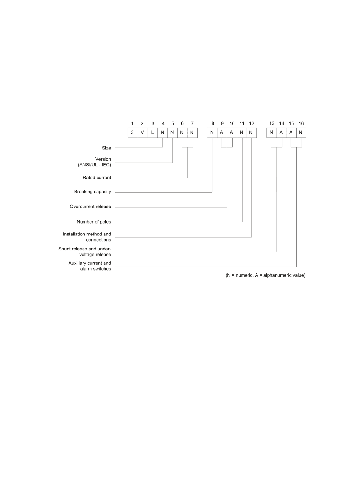
The table below describes the order number scheme according to which all circuit breakers
can be located and combined to suit the individual application:
Figure 2-1 Overview of the order number system
3VL IEC molded case circuit breakers
System Manual, 11/2013, 110 0110 - 02 DS 03
15


3
3.1
Overview 3VL
SENTRON VL types
Type designation
Maximum rated current (A)
VL160X / 3VL1
160
VL160 / 3VL2
160
VL250 / 3VL3
250
VL400 / 3VL4
400
VL630 / 3VL5
630
VL800 / 3VL6
800
VL1250 / 3VL7
1250
VL1600 / 3VL8
1600
3VL molded case circuit breakers are climate-proof. They are designed for operation in
enclosed areas. Suitable enclosures must be provided for operation in areas with severe
ambient conditions (such as dust, caustic vapors, hazardous gases).
The type designations of all available molded case circuit breakers are oriented around the
rated current.
3VL IEC molded case circuit breakers
System Manual, 11/2013, 110 0110 - 02 DS 03
17
Product description
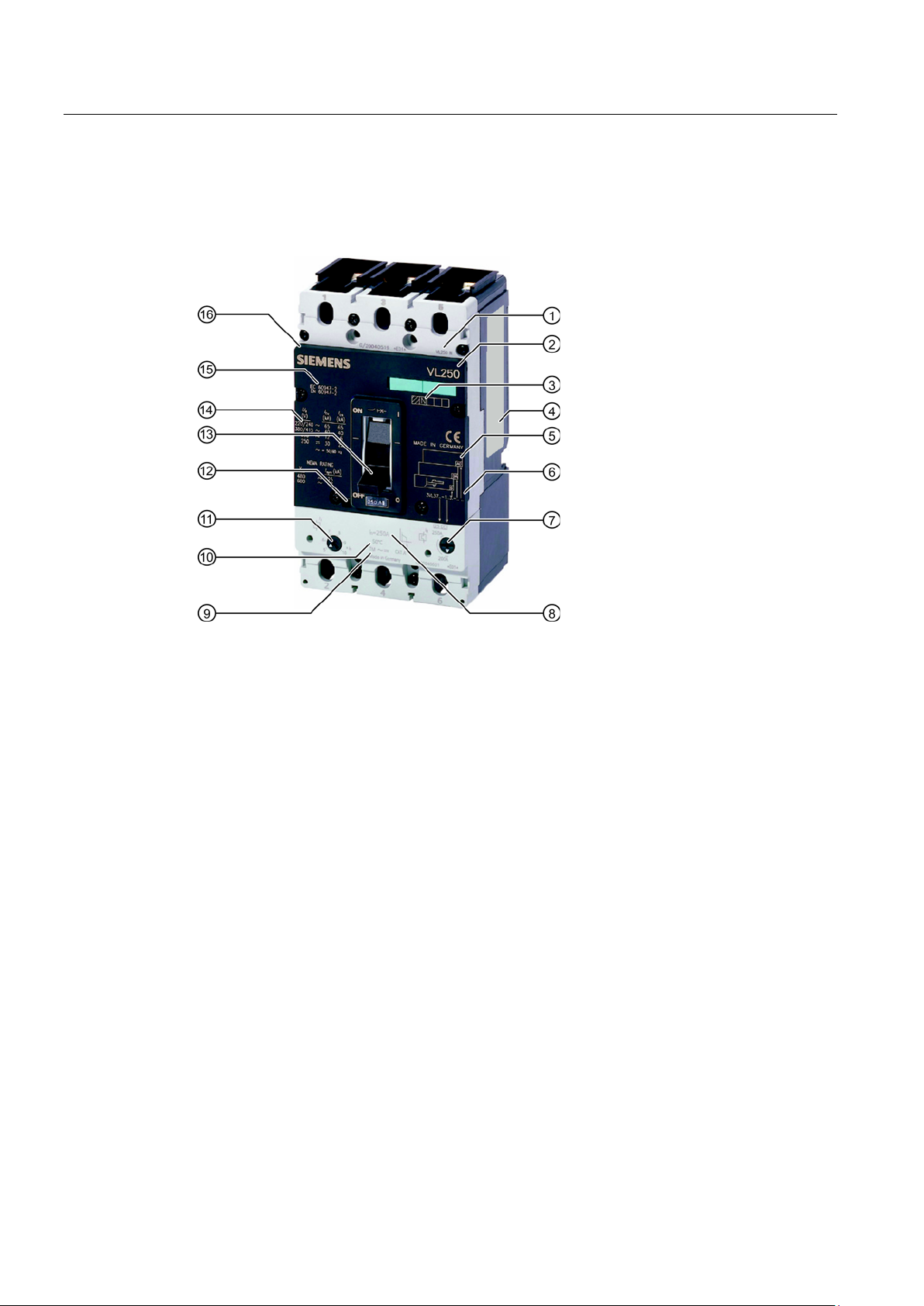
Rating plate and ID number
(1)
Size specification and switching capacity (N, H or L)
(2)
Molded case circuit breaker type
(3)
Indication of switching capacity
(4)
Rating plate
(5)
Accessories ID fields
(6)
Order number
(7)
Overcurrent setting
(8)
In rated current of the molded case circuit breaker
(9)
Overcurrent release type TM (thermal-magnetic)
(10)
Reference temperature
(11)
Short-circuit release / setting
(12)
Test key
(13)
Toggle lever with 3 positions
(14)
Switching capacity
(15)
Standards
(16)
Accessories cover (removable)
3.1 Overview 3VL
The figure shows all the operator elements, setting options and names corresponding to the
precise specified use of the molded case circuit breaker.
Figure 3-1 3VL molded case circuit breakers - labeling and operator controls
3VL IEC molded case circuit breakers
18 System Manual, 11/2013, 110 0110 - 02 DS 03
Product description
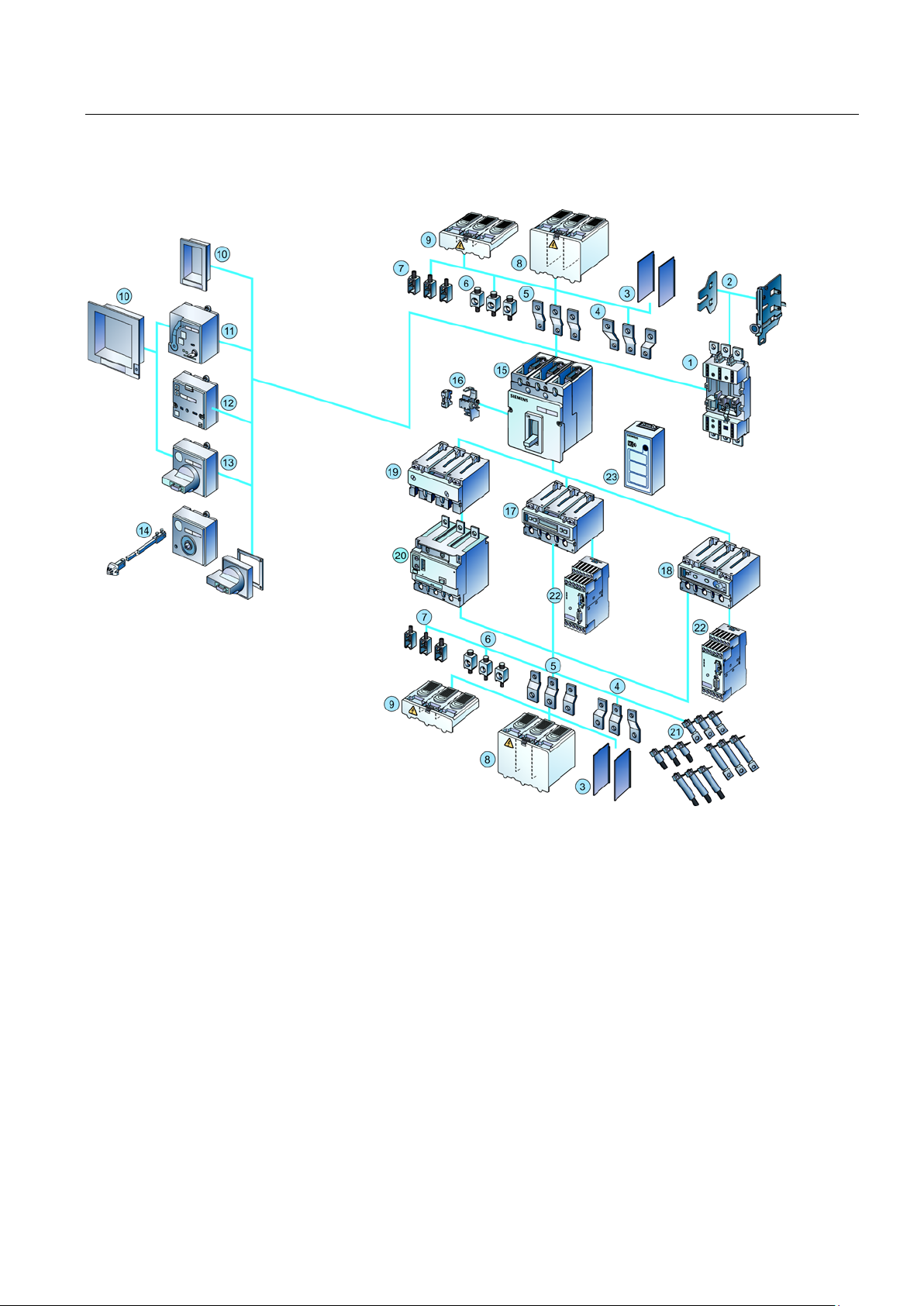
SENTRON VL accessories
(1)
Withdrawable/plug-in base
(13)
Front-operated rotary operating mechanism
(2)
Side panels of withdrawable unit
(14)
Door-coupling rotary operating mechanism
(3)
Phase barriers
(15)
3VL molded case circuit breaker
(4)
Front connecting bars for increased pole spacing
(16)
Internal accessories
(5)
Straight connecting bars
(17)
Electronic trip unit LCD ETU
(6)
Circular conductor terminal for Al / Cu
(18)
Electronic trip unit with communication function
(7)
Box terminal for Cu
(19)
Thermal/magnetic overcurrent release
(8)
Extended terminal cover
(20)
RCD module
(9)
Standard terminal cover
(21)
Rear terminals - flat and round
PROFIBUS DP / MODBUS RTU
energy mechanism (SEO)
Battery power supply with test function for electronic trip
units (ETUs)
(12)
Motorized operating mechanism (MO)
3.1 Overview 3VL
(10) Masking/cover frame for door cutout (22) COM20 / 21 communication module to the
(11) Motorized operating mechanism with stored
Figure 3-2 SENTRON VL accessories
3VL IEC molded case circuit breakers
System Manual, 11/2013, 110 0110 - 02 DS 03
(23)
19
Product description
3.2
Application overview
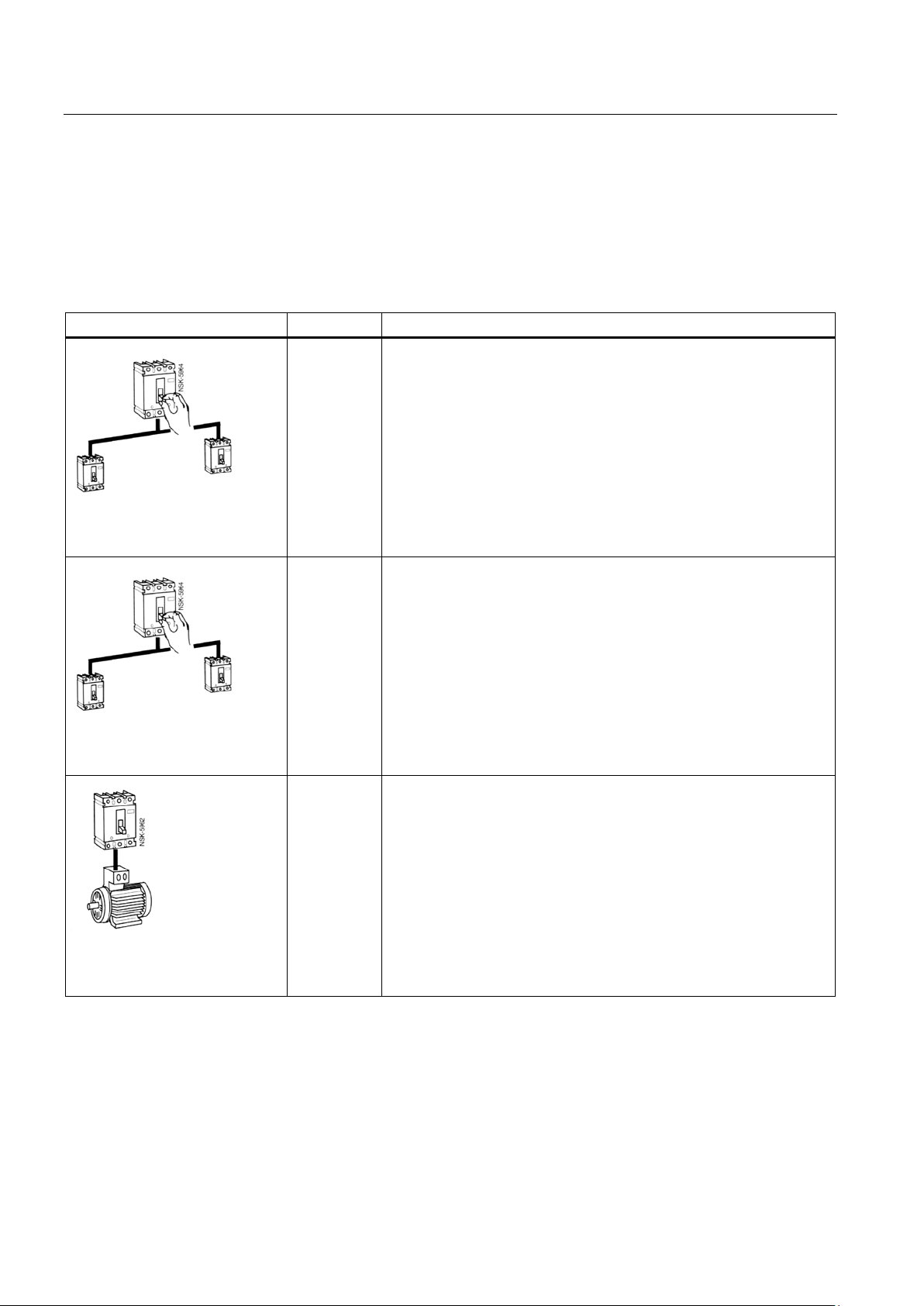
Application overview
Application
Type
Description
System protection
Generator protection
Motor protection
3.2 Application overview
The following overview shows the most frequently occurring applications.
VL160X
The releases for system protection are designed to protect cables and
non-motorized loads against overload and short-circuit.
3- and 4-pole molded case circuit
breakers
VL160
VL250
VL400
VL630
VL800
VL125
VL1600
3- and 4-pole molded case circuit
breakers
3-pole molded case circuit
breakers
VL160
VL250
VL400
VL630
VL800
VL125
VL1600
VL160
VL250
VL400
VL630
The overload and short-circuit releases can be used for optimized
protection of generators.
The overload and short-circuit releases are designed for optimal
protection and direct starting of three-phase AC squirrel-cage motors.
The molded case circuit breakers for motor protection have phasefailure sensitivity and a thermal image that protects the motor against
overheating. The adjustable time lag class enables users to adjust the
overload release to the startup conditions of the motor to be protected.
3VL IEC molded case circuit breakers
20 System Manual, 11/2013, 110 0110 - 02 DS 03
Product description
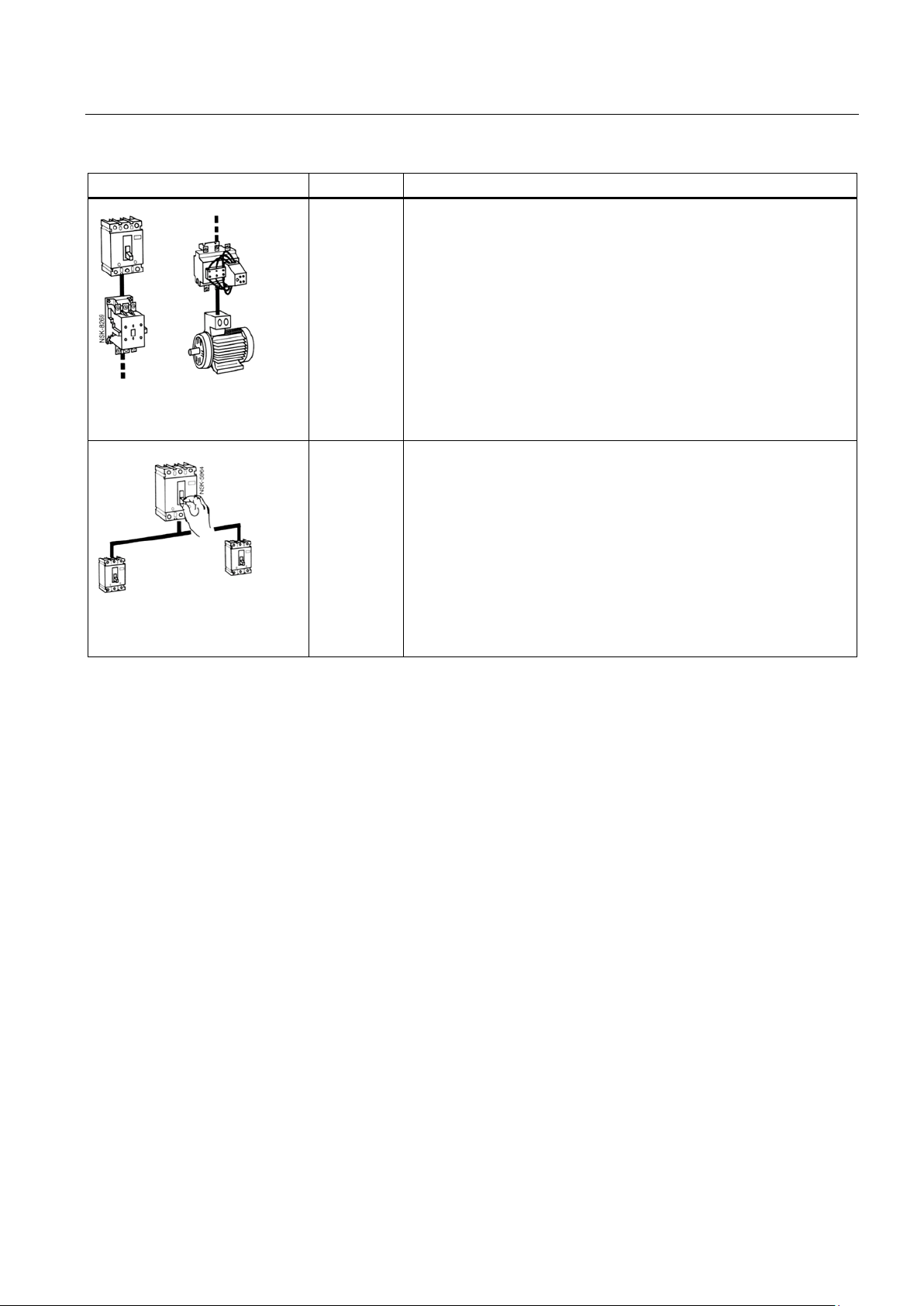
Application
Type
Description
Starter combination
Starter combinations consist of: molded case circuit breaker + contactor
Non-automatic air circuit breakers
3.2 Application overview
VL160
3-pole molded case circuit
breakers
3- and 4-pole molded case circuit
breakers
VL250
VL400
VL630
VL160X
VL160
VL250
VL400
VL630
VL800
VL1250
VL1600
+ overload relay. The molded case circuit breaker handles short-circuit
protection and the isolating function. The contactor has the task of
switching the load feeder normally. The overload relay handles
overload protection that can be specially matched to the motor. The
molded case circuit breaker for starter combination is therefore
equipped with an adjustable and instantaneous short-circuit release.
These molded case circuit breakers are used as incoming circuit
breakers, main switches or isolating switches without overload
protection. They have fixed short-circuit releases so that back-up fuses
are not necessary.
3VL IEC molded case circuit breakers
System Manual, 11/2013, 110 0110 - 02 DS 03
21

Product description
3.3
Configuration
3.3.1
Functional principle
Mechanical design
Current limiting
3.3.2
Subdivision according to power ranges
VL160X molded case circuit breakers
3.3 Configuration
All 3VL molded case circuit breakers have a trip-free mechanism that ensures the trip
process is not prevented even if the operating mechanism is blocked or manually held in the
"ON" position.
The contacts are opened and closed by a toggle lever positioned in the center. This is
attached to the front side on all molded case circuit breakers.
All 3VL molded case circuit breakers are "joint trip units". This means all contacts open or
close simultaneously when the molded case circuit breaker toggle lever is moved from "OFF"
to "ON" or from "ON" to "OFF", or when the tripping mechanism is activated by an
overcurrent or with the help of the auxiliary trips (shunt release or undervoltage release).
The 3VL molded case circuit breakers are designed on the principle of magnetic repulsion of
the contacts. The contacts open before the expected peak-value of the short-circuit current is
reached. Magnetic repulsion of the contacts very considerably reduces the thermal load I
as well as the mechanical load resulting from the impulse short-circuit current I
system components that occur during a short-circuit.
You can find more information in the chapter Use in motor protection (Page 64).
The most important components of the VL160X molded case circuit breakers are the three
current paths with the incoming and outgoing terminals. The fixed and movable contacts are
arranged in such a way as to guarantee magnetic repulsion of the contacts. In conjunction
with the arcing chambers, a dynamic impedance is generated that causes current limitation.
This reduces the damaging effects of excessively high values I
The overcurrent release is a factory-installed thermal-magnetic device. It is equipped with
fixed or adjustable overload releases and a fixed short-circuit release in each pole.
To the right and left of the centrally positioned toggle lever of every SENTRON VL molded
case circuit breaker is a double-insulated accessory compartment for installing auxiliary
switches or alarm switches as well as shunt releases and undervoltage releases.
2
t and Ip.
of the
P
2
t
3VL IEC molded case circuit breakers
22 System Manual, 11/2013, 110 0110 - 02 DS 03

Product description
VL160 to VL630 molded case circuit breakers
VL800 to VL1600 molded case circuit breakers
3.3.3
Thermal-magnetic overcurrent trip units
Thermal release
3.3 Configuration
The arrangement of current paths, contact configuration and switch mechanism of the VL160
to VL630 molded case circuit breakers corresponds to that of the VL160X molded case
circuit breaker. The designs diverge with regard to the overcurrent release.
● The overcurrent releases are available in a thermal-magnetic version and in an electronic
version.
● Thermal-magnetic overcurrent releases are available with adjustable overload releases
and short-circuit releases.
The arrangement of the current paths and switch mechanisms is identical to that of the
VL160X to VL630 molded case circuit breakers.
However, the VL800 to VL1600 molded case circuit breakers are only available in the
version with electronic trip unit. As with all electronic trip units for the SENTRON VL molded
case circuit breakers from Siemens, the current transformers (one per phase) are
accommodated within the overcurrent release enclosure.
All 3VL molded case circuit breakers with electronic trip units measure the actual RMS
current. This method is the most accurate way of measuring currents in electrical distribution
systems with extremely high harmonics.
A thermal-magnetic overcurrent release consists of two components - a thermal release for
protecting against overload, and a magnetic release for protecting against short-circuit. Both
release components are series-connected.
The thermal release consists of a temperature-dependent bimetal that heats up as a result of
the flow of current. This means the release is current-dependent. The heating of the bimetal
strip depends on the ambient temperature of the molded case circuit breaker. All current
values specified for 3VL for thermal-magnetic releases refer to an ambient temperature of 40
°C. Where ambient temperatures deviate from this, the values in the tables in the chapter
Use at altitudes above 2000 meters (Page 142) are to be used.
3VL IEC molded case circuit breakers
System Manual, 11/2013, 110 0110 - 02 DS 03
23

Product description
Magnetic release
3.3.4
Electronic overcurrent trip unit (ETU)
Electronic trip units (ETUs)
Configuration
Power supply
3.3 Configuration
The magnetic release comprises a yoke mounting through which a current path runs, and a
flap armature that is kept at a distance from the yoke mounting by a tension spring. If a
short-circuit current now flows along the current path, the magnetic field thus generated
causes the flap armature to be moved towards the yoke mounting against the opposite force
of the tension spring. The release time is almost current-independent and instantaneous.
The flap armature releases the switching lock and thus opens the switching contacts before
the short-circuit current can reach its maximum; a current limiting effect is thus achieved.
Immediately after release, the flap armature is moved back to its starting position by the
opposite force of the tension spring.
In contrast to thermal-magnetic releases/trip units (TMTUs) where the overcurrent trip is
caused by a bimetal strip or magnetic release, electronic trip units (ETUs) use electronics
with current transformers. The ETU captures the actual currents and compares them with the
default specifications.
All 3VL molded case circuit breakers with electronic overcurrent trips measure the actual
RMS current (true RMS). This is the most accurate method of measuring.
ETUs are available from the VL160 molded case circuit breaker up to and including the
VL1600. The VL800, VL1250 and VL1600 molded case circuit breakers are only available in
the version with electronic trip unit.
The electronic overcurrent tripping system consists of:
● 3 to 4 (3-pole or 4-pole) current transformers that also provide their own power supply.
This means an external auxiliary voltage is not required.
● Evaluation electronics with microprocessor
● Tripping solenoid
In all versions with electronic trip units for the 3VL molded case circuit breakers, the current
transformers are located in the same enclosure as the trip unit. At the output of the electronic
overcurrent tripping module, there is a tripping solenoid that trips the molded case circuit
breaker in the event of an overload or short-circuit. In all electronic trip units, the tripping
solenoid is located within the trip unit, except in the shipbuilding ETUs of sizes VL160 and
VL250. In these ETUs, the tripping solenoid is located in the left accessories compartment.
The protection functions of the electronic trip unit are guaranteed without additional auxiliary
voltage. The overcurrent releases are supplied with energy via internal current transformers.
The protection function is set via rotary encoding switches on the ETU or via an LCD display.
3VL IEC molded case circuit breakers
24 System Manual, 11/2013, 110 0110 - 02 DS 03
Product description
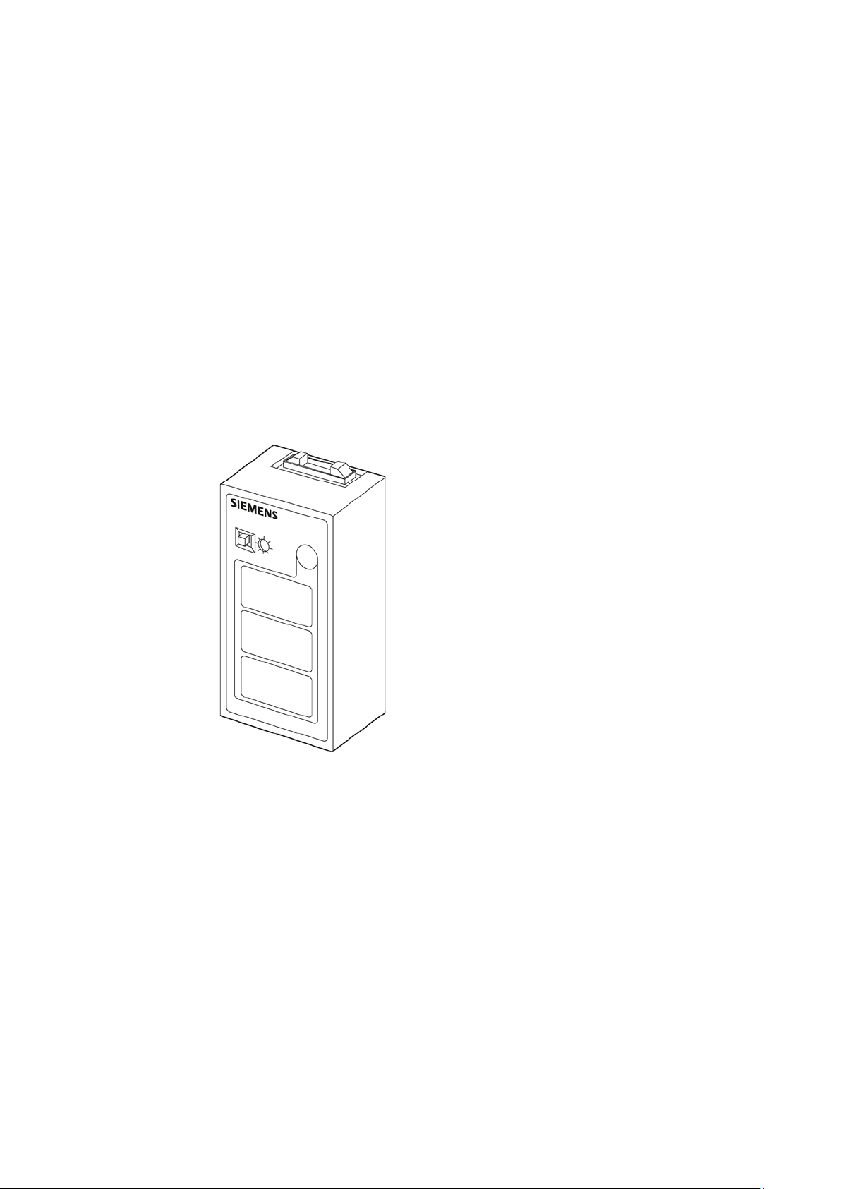
Battery supply device
4-pole molded case circuit breakers
3.3 Configuration
In the case of an LCD display, the electronic trip unit must be activated. This requires a 3phase (3-pole) load current of at least 20% or, in the case of a single-phase (single-pole)
load, 30% of the relevant rated current of the molded case circuit breaker. If this load current
is not available, the necessary auxiliary energy can be supplied via a battery power supply
(order no. 3VL9000-8AP01). With communication-capable, molded case circuit breakers, the
trip unit is powered by means of the COM20 or COM21 module.
The handheld tester for electronic trip units is used as a local test device for the 3VL molded
case circuit breakers with electronic trip unit, and it can be used as an external voltage
supply for the electronic trip units (ETU and LCD-ETU). The portable battery power supply is
fed by two standard 9 V block batteries.
Test function:
● Test tripping
Figure 3-3 Battery supply device
The four-pole molded case circuit breakers for system protection can be supplied in all
4 poles with or without current transformers. The trip units in the 4th pole (N) can be set to
50% or 100% of the current in the 3 main current paths dependent on the size, so that safe
protection of the neutral conductor can be guaranteed even with a reduced cross-section. In
the case of LCD-ETUs, the neutral conductor protection can be adjusted in steps from 50%
to 100% or switched off.
3VL IEC molded case circuit breakers
System Manual, 11/2013, 110 0110 - 02 DS 03
25

Product description
3.4
Mechanical operating mechanisms
3.4.1
Toggle lever operating mechanism
Toggle lever positions
OFF
RESET
Tripped
Toggle lever positions
3.4 Mechanical operating mechanisms
In the basic version, the 3VL molded case circuit breakers have a toggle lever as actuator,
which is also an indicator of the switching position. The "Tripped" position is also displayed in
addition to the "ON" and "OFF" positions.
The toggle lever goes to the "tripped" position when the internal trip mechanism is activated
by an overcurrent situation, e.g. overload or short-circuit, or if the Test key is operated.
Activation by an undervoltage release or shunt release will also cause the toggle lever to
move to the "Tripped" position.
The toggle lever must be returned to the "OFF/RESET" position before the molded case
circuit breaker can be activated again. This enables the internal release mechanism to be
reset. 3VL molded case circuit breakers with toggle lever operation comply with the "Network
disconnecting device" condition (5.3.2 Section c) and 5.3.3) according to DIN EN 60204-1
(VDE 0113-1) in conjunction with a locking device.
3VL IEC molded case circuit breakers
26 System Manual, 11/2013, 110 0110 - 02 DS 03
Product description
Toggle lever extension
Toggle lever extension
Use of toggle lever extension
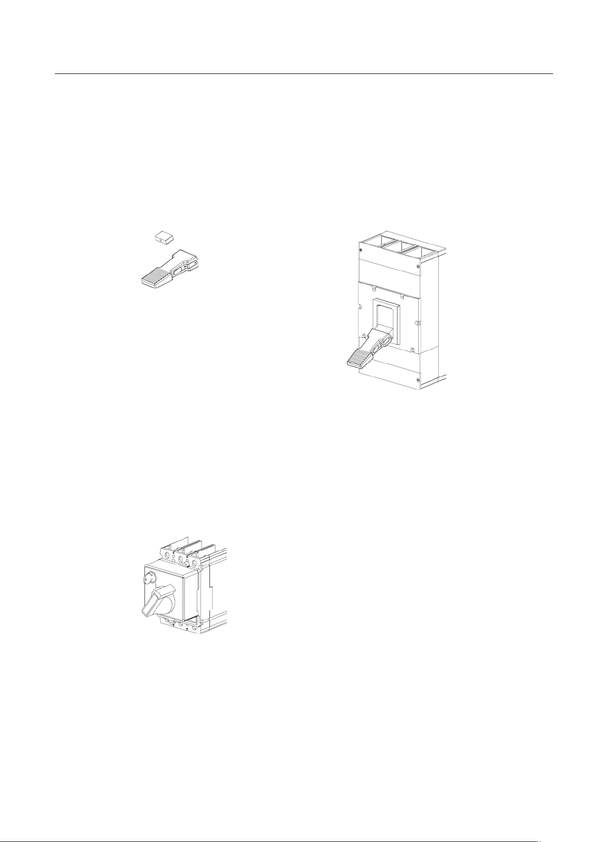
3.4.2
Rotary mechanism on front (optional)
Rotary mechanism
The front
on the molded case circuit breaker. 3VL
breakers with rotary mechanism comply with the "Network
disconnecting device" conditi
-
1).
3.4 Mechanical operating mechanisms
Toggle lever extensions enable user-friendly operation of the molded case circuit breaker
toggle lever.
● VL160X to VL250: toggle lever extension not necessary / not available
● VL400 to VL800: possible as option
● VL1250 to VL1600: included in the scope of supply / optional installation
The front-operated rotary operating mechanism converts the vertical movement of the toggle
lever into rotary motion. The molded case circuit breaker is switched on/off or tripped with
the help of the front-operated rotary operating mechanism. The rotary motion on the
switching knob is converted to vertical motion on the toggle lever.
-operated rotary operating mechanism is mounted directly
molded case circuit
on of DIN EN 60204-1 (DIN VDE 0113
3VL IEC molded case circuit breakers
System Manual, 11/2013, 110 0110 - 02 DS 03
27

Product description
Degree of protection
Interlocking
Application
Accessories
3.4 Mechanical operating mechanisms
The front-operated rotary operating mechanism has degree of protection IP30.
Lockable in the "OFF" position with up to 3 padlocks.
A safety lock can also be used.
Standard application:
● Black knob
● Gray indicator plate
Network disconnecting device with features for stopping and shutting down in an emergency:
● Red knob
● Yellow indicator plate
Optionally, up to 4 changeover contacts can be used. Two contacts can be used as leading
NO contacts and two contacts as leading NC contacts. These are equipped with 1.5 m long
connection cables.
3VL IEC molded case circuit breakers
28 System Manual, 11/2013, 110 0110 - 02 DS 03

Product description
3.4.3
Door-coupling rotary operating mechanism (optional)
Door
mechanism
3VL
mechanism comply with the "Network disconnecting
device" con
Degree of protection
Interlocking
Application
3.4 Mechanical operating mechanisms
The door-coupling rotary operating mechanism is available for installation in control cabinets
and distribution boards.
molded case circuit breakers with door-coupling rotary
dition of DIN EN 60204-1 (DIN VDE 0113-1)
-coupling rotary operating
The door-coupling rotary operating mechanism is designed as follows:
● Rotary mechanism on the front with shaft stub (without knob)
● Shaft coupling
● 300 mm extension shaft (600 mm optional, retaining bracket required)
● Actuator
This mechanism offers degree of protection IP65.
Lockable in the "OFF" position with up to 3 padlocks. A safety lock can also be used.
Standard application:
● Black knob
● Gray indicator plate
Network disconnecting device with features for stopping and shutting down in an emergency:
● Red knob
● Yellow indicator plate
3VL IEC molded case circuit breakers
System Manual, 11/2013, 110 0110 - 02 DS 03
29
Product description
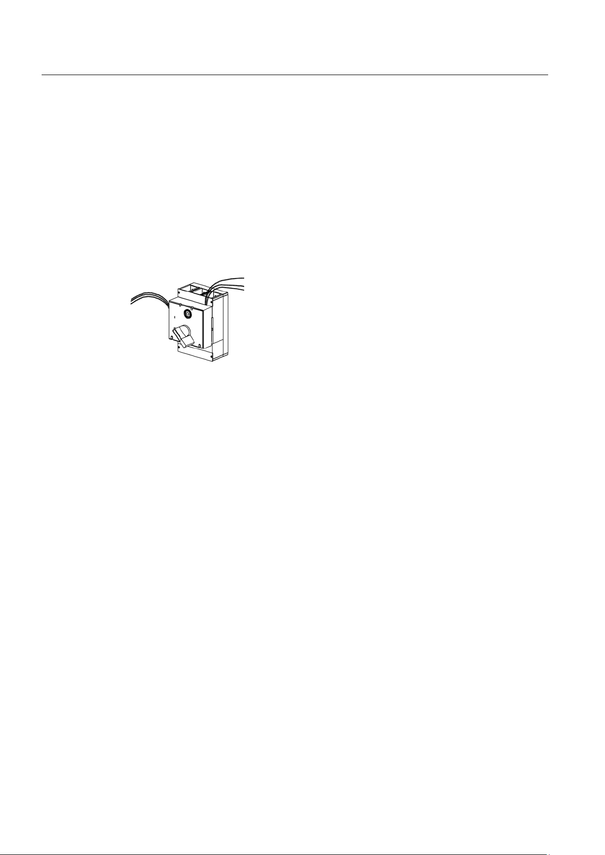
Accessories
Leading auxiliary switches when switching ON and OFF
3.4.4
Side panel rotary operating mechanism (optional)
3.4 Mechanical operating mechanisms
The leading auxiliary switches (changeover switches) are available as accessories for frontoperated rotary operating mechanisms and door-coupling rotary operating mechanisms.
The following applications are possible:
● Leading auxiliary switch for switching from "ON" to "OFF"
● Leading auxiliary switch for switching from "OFF" to "ON"
Each version, leading auxiliary switch for switching on and off, can be equipped with one or
two changeover switches. The connecting cables of the auxiliary switches are 1.5 m long.
Figure 3-4 Rotary operating mechanism with leading auxiliary switches
The side panel rotary operating mechanism is available for installation in control cabinets
and distribution boards.
3VL IEC molded case circuit breakers
30 System Manual, 11/2013, 110 0110 - 02 DS 03
 Loading...