

Siemens SENTRON 3VL System Manual
Switching/protection devices
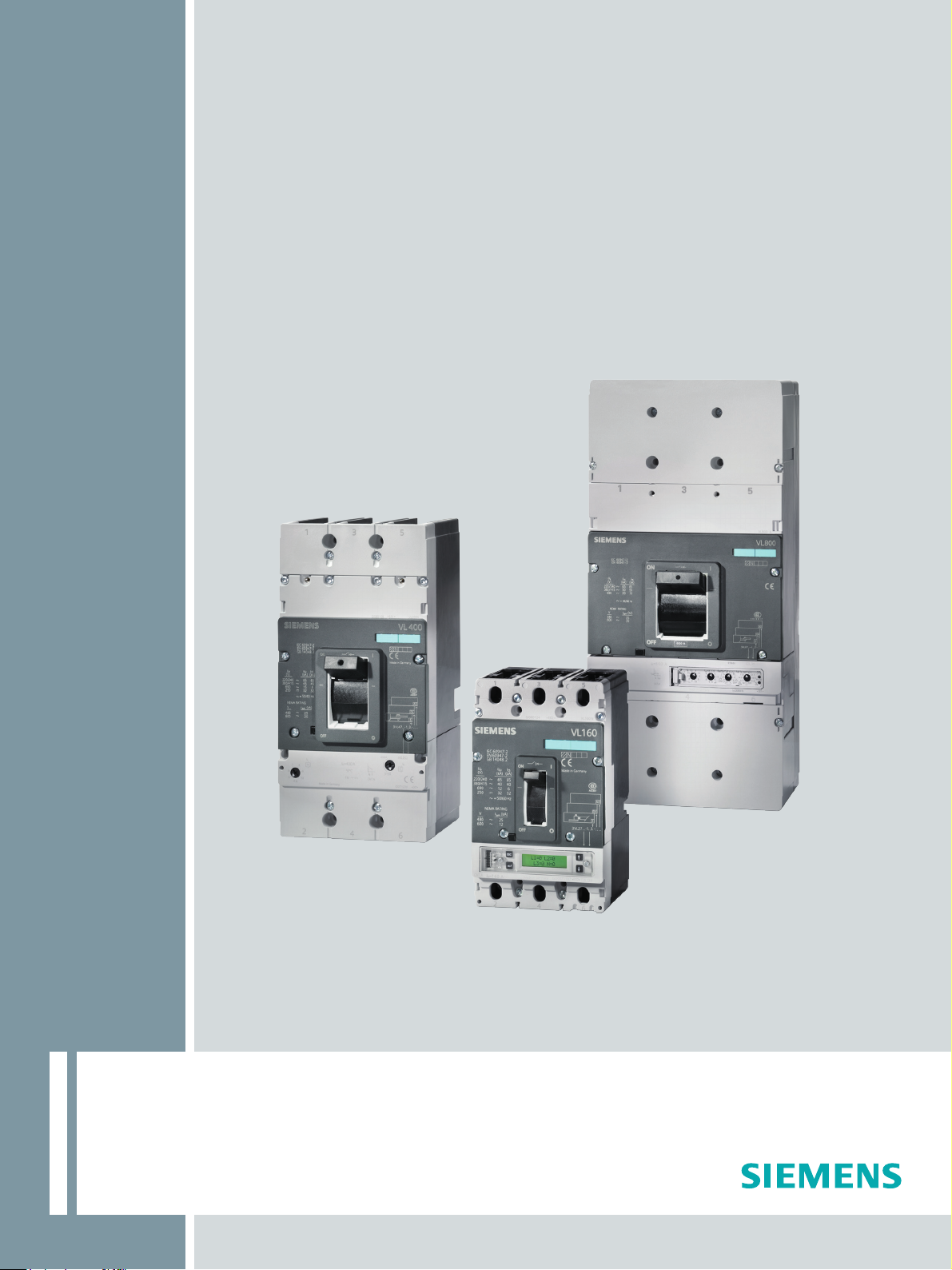
3VL molded-case circuit breakers
System Manual
•
03/2009
SENTRON
Answers for industry.


SENTRON
Switching/protection devices
3VL molded-case circuit breakers
System Manual
03/2009
110 0110 - 02 DS 01
About this document
Product-specific information
Product description
System overview
Functions
Application planning
Installing/mounting
Connecting
Displays and operator
controls
Parameter
assignment/addressing
Service and maintenance
Technical data
Dimensional drawings
Circuit diagrams
Spare parts/accessories
ESD guidelines
Appendix
1
2
3
4
5
6
7
8
9
10
11
12
13
14
15
A
B
Legal information
Warning notice system
This manual contains notices you have to observe in order to ensure your personal safety, as well as to prevent
damage to property. The notices referring to your personal safety are highlighted in the manual by a safety alert
symbol, notices referring only to property damage have no safety alert symbol. These notices shown below are
graded according to the degree of danger.
DANGER
indicates that death or severe personal injury will result if proper precautions are not taken.
WARNING
indicates that death or severe personal injury may result if proper precautions are not taken.
CAUTION
with a safety alert symbol, indicates that minor personal injury can result if proper precautions are not taken.
CAUTION
without a safety alert symbol, indicates that property damage can result if proper precautions are not taken.
NOTICE
indicates that an unintended result or situation can occur if the corresponding information is not taken into
account.
If more than one degree of danger is present, the warning notice representing the highest degree of danger will
be used. A notice warning of injury to persons with a safety alert symbol may also include a warning relating to
property damage.
Qualified Personnel
The device/system may only be set up and used in conjunction with this documentation. Commissioning and
operation of a device/system may only be performed by qualified personnel. Within the context of the safety notes
in this documentation qualified persons are defined as persons who are authorized to commission, ground and
label devices, systems and circuits in accordance with established safety practices and standards.
Proper use of Siemens products
Note the following:
WARNING
Siemens products may only be used for the applications described in the catalog and in the relevant technical
documentation. If products and components from other manufacturers are used, these must be recommended
or approved by Siemens. Proper transport, storage, installation, assembly, commissioning, operation and
maintenance are required to ensure that the products operate safely and without any problems. The permissible
ambient conditions must be adhered to. The information in the relevant documentation must be observed.
Trademarks
All names identified by ® are registered trademarks of the Siemens AG. The remaining trademarks in this
publication may be trademarks whose use by third parties for their own purposes could violate the rights of the
owner.
Disclaimer of Liability
We have reviewed the contents of this publication to ensure consistency with the hardware and software
described. Since variance cannot be precluded entirely, we cannot guarantee full consistency. However, the
information in this publication is reviewed regularly and any necessary corrections are included in subsequent
editions.
Siemens AG
Industry Sector
Postfach 48 48
90026 NÜRNBERG
GERMANY
Ordernumber: 3ZX1012-0VL10-0AC1
Ⓟ 03/2009
Copyright © Siemens AG 2009.
Technical data subject to change

Table of contents
1 About this document...........................................................................................................
1.1 Introduction ..................................................................................................................................11
2 Product-specific informatio
2.1 Important notes ...............................................................................................................
3 Product description...........................................................................................................
3.1 SENTRON VL overvi
3.2 Application overview ....................................................................................................................18
3.3 Configuration................................................................................................................................19
3.3.1 Functional principle ......................................................................................................................19
3.3.2 Subdivision according to power ranges
3.3.3 Thermomagnetic overcurrent trip units ........................................................................................20
3.3.4 Electronic
3.4 Mechanical operating mechanisms .............................................................................................23
3.4.1 Toggle handl
3.4.2 Rotary mechanism on front (optional)..........................................................................................24
3.4.3 Door-coupling rotary operating mechanism (optional).................................................................25
3.5 Motoriz
3.5.1 Stored-energy motori
3.5.2 Motorized operating mechanism without stored-energy mechanism ..........................................27
4 System overview...................................................................................................................................... 29
overcurrent trip unit (ETU) ........................................................................................
ed operating mechanisms (optional)................................................................................26
n..................................................................................................
ew...............................................................................................................15
.......................................................................................19
e operating mechanism
zed operating mechanism
...........................................................................................23
..........................................................................27
..................... 11
................... 13
.............13
....................... 15
..21
4.1 Possible applications ...................................................................................................................29
4.2 Key data.......................................................................................................................................30
4.2.1 General data - 3VL molded-case circuit breakers .......................................................................30
itches................................................................................34
4.2.2 General data - auxiliary and alarm
4.2.3 General data - Trip units ..............................................................................................................36
4.2.4 General data
5 Funct
6 Application planning
3VL molded-case circuit breakers
System Manual, 03/2009, 110 0110 - 02 DS 01
ions................................................................................................................................................. 41
5.1 Current protection ........................................................................................................................41
5.1.1 Overcurrent trip unit
5.1.2 Func
5.1.3 Setting options .............................................................................................................................46
5.1.4 Dimensioning short-circuit protection according to frame size ....................................................47
5.1.5 General technical specifications ..................................................................................................48
5.1.6 Differential current protection with RCD module..........................................................................51
5.1.7 Single-pole operation with
5.1.8 Ground-fault protection .......................................................................................................
5.2 Voltage protection ........................................................................................................................60
5.2.1 Underv
5.2.2 Shunt release...............................................................................................................................62
5.2.3 Auxiliary switches and alarm swit
tion overview ........................................................................................................................44
- motorized operating mechanisms........................................................................38
.....................................................................................................................41
RCD module
oltage release...................................................................................................................60
................................................................................................................................. 65
sw
......................................................................................56
ches.........................................................................................63
.........58
5

Table of contents
6.1 Use with frequency converters.................................................................................................... 65
6.2 Use of capacitor banks................................................................................................................ 67
6.3 Primary-side transformer protec
6.4 Use in DC sys
tems...................................................................................................................... 69
tion............................................................................................ 68
6.5 Use in IT networks ...................................................................................................................... 71
6.6 Use in the motor protec
6.7 Use in harsh environments:
tion area..............................................................................................
........................................................................................................ 78
6.8 Use in series connection ............................................................................................................. 81
7 Installing/mounting
...........................................................................................................
........................ 83
7.1 Installation methods .................................................................................................................... 83
7.2 Mounting and safety cl
earances
................................................................................................. 87
7.3 Locking devices........................................................................................................................... 91
8 Connecting
....................................................................................................................
.......................... 97
8.1 Cables and busbars .................................................................................................................... 97
8.2 Main connection types for fixed mounting................................................................................. 107
8.3 Main connection methods for plug-in and withdrawable version.............................................. 114
8.4 Terminal assignment
s..........................................................................................................
8.5 Auxiliary switch designations .................................................................................................... 118
8.6 Des
cription of the terminals....................................................................................................... 118
... 74
..... 116
9 Displa
ys and operator controls
.............................................................................................................. 121
9.1 Overcurrent trip unit without LCD display ................................................................................. 121
9.2 Overcurrent trip unit with LCD display ...................................................................................... 125
9.3 Stored-energy motori
10 Parameter assignment/add
zed operating mechanism
ressing ........................................................................................................ 135
....................................................................... 133
10.1 Setting the parameters.............................................................................................................. 135
Setting the protection parameters for motor protection (ETU10M, ETU30M and LCD-ETU
10.2
40M) ..........................................................................................................................
11 Service and maintenan
ce .......................................................................................................
................ 139
11.1 Preventive measures ................................................................................................................ 141
11.2 Troubleshooting ........................................................................................................................ 143
12 Technical
12.1
12.2 Configuration of main connections
data ....................................................................................................................................... 145
Technical overview
.................................................................................................................... 145
............................................................................................ 150
12.3 Switching capacity overview ..................................................................................................... 153
12.4 Switching capacity overview ..................................................................................................... 157
......................................................................................................................... 159
12.5 Derating fac
tors
12.6 Power loss................................................................................................................................. 167
............... 141
3VL molded-case circuit breakers
6 System Manual, 03/2009, 110 0110 - 02 DS 01

Table of contents
12.7 Mechanical operating mechanisms ...........................................................................................170
12.8 Motorized operating mechanisms ..............................................................................................171
12.9 Capacitor banks .........................................................................................................................173
12.10 Motor Protection.........................................................................................................................174
12.11 RCD modules.............................................................................................................................177
12.12 Undervoltage release.................................................................................................................178
12.13 Undervoltage release connection data ......................................................................................180
12.14 Shunt release .............................................................................................................................182
12.15 Shunt release connec
tion data
..................................................................................................184
12.16 Auxiliary switches and alarm switches.......................................................................................185
Position signaling switch ............................................................................................................187
12.17
12.18 Ground fault protection classes .................................................................................................188
12.19 IP degrees of protection
13 Dimen
sional drawi
ngs............................................................................................................................ 191
.............................................................................................................189
13.1 VL160X (3VL1), VL160 (3VL2), and VL250 (3VL3), 3- and 4-pole, to 250 A............................191
13.1.1 Circ
uit breakers..........................................................................................................................191
13.1.2 Operating mechanisms ..............................................................................................................193
13.1.3 Connections and phase barriers
13.1.4 Terminal c
overs .........................................................................................................................197
13.1.5 Locking device for the toggle handl
13.1.6
Rear locking module ..................................................................................................................198
Accessories................................................................................................................................200
13.1.7
................................................................................................195
e .........................................................................................198
13.1.8 Door cutouts...............................................................................................................................202
13.1.9 Plug-in socket and accessories
13.1.10 VL160X (3V
13.1.10.1 Plug-in
13.1.11 VL160 (3VL)
13.1.11.1
Withdrawable version and accessories .....................................................................................208
L1), 3- and 4-pole, up to 160 A...............................................................................206
socket and accessories .................................................................................................206
and VL250 (3VL3), 3- and 4-pole, up to 250 A.....................................................208
13.2 VL400 (3VL4), 3- and 4-pole, up to 400 A
13.2.1 Circ
uit breaker............................................................................................................................211
.................................................................................................204
.................................................................................211
13.2.2 Operating mechanisms ..............................................................................................................212
13.2.3 Connections and phase barriers
13.2.4 Terminal c
13.2.5 Rear interlocking module
13.2.6
Locking devices, locking device for toggle handle and
overs .........................................................................................................................215
...........................................................................................................216
................................................................................................213
accessories..........................................216
13.2.7 Door cutouts...............................................................................................................................219
13.2.8 Plug-in socket and accessories
.................................................................................................221
13.3 VL630 (3VL5), 3- and 4-pole, up to 630 A .................................................................................227
13.3.1 Circ
uit breaker............................................................................................................................227
13.3.2 Operating mechanisms ..............................................................................................................228
13.3.3 Connections and phase barriers
13.3.4 Terminal c
13.3.5 Rear interlocking module
13.3.6
Locking and locking device for toggle handle............................................................................232
13.3.7 Ac
cessories................................................................................................................................233
overs .........................................................................................................................230
...........................................................................................................231
................................................................................................229
13.3.8 Door cutouts...............................................................................................................................235
13.3.9 Plug-in socket and accessories
3VL molded-case circuit breakers
System Manual, 03/2009, 110 0110 - 02 DS 01
.................................................................................................237
7

Table of contents
13.3.10 Withdrawable version and accessories..................................................................................... 239
13.4 VL800 (3VL6), 3- and 4-pole, up to 800 A ................................................................................ 242
13.4.1 Circ
uit breaker........................................................................................................................... 242
13.4.2 Operating mechanisms ............................................................................................................. 243
13.4.3 Withdrawable version................................................................................................................ 244
13.4.4 Connections and phase barriers
13.4.5 Terminal c
overs......................................................................................................................... 249
13.4.6 Locking and locking device for toggle handle
............................................................................................... 248
........................................................................... 250
13.4.7 Rear interlocking module .......................................................................................................... 251
13.4.8
Accessories............................................................................................................................... 252
13.4.9 Door cutouts.............................................................................................................................. 254
13.5 VL1250 (3VL7) and VL 1600 (3VL8), 3-
and 4-pole, up to 1600 A
........................................... 256
13.5.1 Circuit breaker........................................................................................................................... 256
13.5.2 Operating mechanisms ............................................................................................................. 258
13.5.3 Withdrawable version................................................................................................................ 260
13.5.4 Connections and phase barriers
13.5.5 Terminal c
13.5.6 Rear interlocking module
13.5.7
Locking and locking device for toggle handle ........................................................................... 269
13.5.8 Ac
cessories............................................................................................................................... 269
overs......................................................................................................................... 265
.......................................................................................................... 268
............................................................................................... 264
13.5.9 Door cutouts.............................................................................................................................. 271
13.5.10 Current transformer................................................................................................................... 272
13.6 VL160X (3VL1) up to VL800 (3VL6), 3- and 4-pole, up to 800 A ............................................. 273
wi
......................................................................................................... 273
13.6.1 Locking with bowden
re
13.6.2 Busbar adapter system 8US1 ................................................................................................... 275
13.7 VL160X (3VL1) with RCD block, 3- and 4-pol
13.7.1
Circuit breakers ......................................................................................................................... 276
13.7.2 Connections and phase barriers
13.7.3 Terminal c
overs......................................................................................................................... 279
............................................................................................... 277
e, up to 160 A.................................................... 276
13.7.4 Door cutouts.............................................................................................................................. 281
13.7.5 Plug-in socket and accessories
13.8 VL160 (3VL2
) and VL250 (3VL3) with RCD module, 3- and 4
................................................................................................ 283
-pole, to 250 A.......................... 285
13.8.1 Circuit breakers ......................................................................................................................... 285
13.8.2 Connections and phase barriers
13.8.3 Terminal c
overs......................................................................................................................... 288
............................................................................................... 286
13.8.4 Door cutouts.............................................................................................................................. 290
13.8.5 Plug-in socket and accessories
................................................................................................ 292
13.9 VL400 (3VL4) with RCD m
odule, 3- and 4-pole, up to 400 A
................................................... 298
13.9.1 Circuit breakers ......................................................................................................................... 298
13.9.2 Connections and phase barriers
13.9.3 Terminal c
overs......................................................................................................................... 302
............................................................................................... 300
13.9.4 Door cutouts.............................................................................................................................. 304
13.9.5 Plug-in socket and accessories
13.10 Door-c
oupling rotary operating mechanisms 8UC
13.11 4NC current transformers for measuring purposes
13.12 COM20/COM21 (communications
13.13 COM10/COM 11 (communications module for SENTRON 3VL)
14 Circuit diagrams
3VL molded-case circuit breakers
..................................................................................................................................... 317
................................................................................................ 306
.................................................................... 312
.................................................................. 315
module for SENTRON 3VL)............................................... 316
.............................................. 316
8 System Manual, 03/2009, 110 0110 - 02 DS 01

Table of contents
15 Spare parts/accessories ........................................................................................................................ 329
15.1 Installation ..................................................................................................................................329
15.2 Electromechanical components .................................................................................................333
15.3 Mechanical components ............................................................................................................335
15.4 Electrical/electronic engineering ................................................................................................337
A ESD guidelin
es ................................................................................................................
...................... 339
A.1 ESD Directive.............................................................................................................................339
B Appendix................................................................................................................................................ 341
B.1 Selectivity...................................................................................................................................341
B.2 Conversion tables ......................................................................................................................344
B.3 Standards and specifications
B.4 Ordering data
Glossary ................................................................................................................................................ 351
.............................................................................................................................348
.....................................................................................................346
3VL molded-case circuit breakers
System Manual, 03/2009, 110 0110 - 02 DS 01
9

Table of contents
3VL molded-case circuit breakers
10 System Manual, 03/2009, 110 0110 - 02 DS 01

About this document
1.1 Introduction
Purpose of this manual
This manual is intended for reference purposes. The information in this manual enables you
to configure and operate the SENTRON VL system.
Audience
This manual is aimed at people with the required qualifications to commission and operate
the SENTRON VL system.
1
3VL molded-case circuit breakers
System Manual, 03/2009, 110 0110 - 02 DS 01
11

About this document
1.1 Introduction
3VL molded-case circuit breakers
12 System Manual, 03/2009, 110 0110 - 02 DS 01

Product-specific information
2.1 Important notes
Validity
This manual applies to SENTRON circuit breakers with the following designations:
● VL160X
● VL160
● VL250
● VL400
● VL630
● VL800
● VL1250
● VL1600
2
Standards and certifications
The SENTRON VL circuit breakers comply with the standards:
● IEC 60947-2 / DIN EN 60947-2 (VDE 0660-101)
● IEC 60947-1 / DIN EN 60947-1 (VDE 0660-100)
● Isolating features in accordance with IEC 60947-3 / EN 60947-3 (VDE 0660-107)
● Network disconnection features for stopping and shutting down in an emergency (main
switch and EMERGENCY-OFF switch) in accordance with IEC 60204-1 / DIN EN 602041 (VDE 0113-1)
Disclaimer of liability
The products described here were developed to perform safety-oriented functions as part of
an overall installation or machine. A complete safety-oriented system generally features
sensors, evaluation units, signaling units, and reliable shutdown concepts. It is the
responsibility of the manufacturer to ensure that a system or machine is functioning properly
as a whole. Siemens AG, its regional offices, and associated companies (hereinafter referred
to as "Siemens") cannot guarantee all the properties of a whole plant or machine that has
not been designed by Siemens.
3VL molded-case circuit breakers
System Manual, 03/2009, 110 0110 - 02 DS 01
13

Product-specific information
2.1 Important notes
Nor can Siemens assume liability for recommendations that appear or are implied in the
following description. No new guarantee, warranty, or liability claims beyond the scope of the
Siemens general terms of supply are to be derived or inferred from the following description.
Up-to-the-minute information
You can obtain further assistance by calling the following numbers:
Technical Assistance: Telephone: +49 (0) 911-895-5900 (8°° - 17°° CET)
Fax: +49 (0) 911-895-5907
or on the Internet at:
e-mail: technical-assistance@siemens.com
Internet: www.siemens.de/lowvoltage/technical-assistance
Technical Support:
Telephone: +49 (0) 180 50 50 222
Correction sheet
A correction sheet is included at the end of the manual. Please use it to record your
suggestions for improvements, additions and corrections, and return the sheet to us. This will
help us to improve the next edition of the manual.
3VL molded-case circuit breakers
14 System Manual, 03/2009, 110 0110 - 02 DS 01

Product description
3.1 SENTRON VL overview
SENTRON VL circuit breakers are resistant to extreme climates. They are designed for use
in closed rooms where no onerous operating conditions prevail (e.g. dust, caustic vapors,
hazardous gases).
SENTRON VL types
The type designations of all available circuit breakers are oriented around the rated current
Type designation Maximum rated current (A)
VL160X 160
VL160 160
VL250 250
VL400 400
VL630 630
VL800 800
VL1250 1250
VL1600 1600
3
3VL molded-case circuit breakers
System Manual, 03/2009, 110 0110 - 02 DS 01
15
Product description
3.1 SENTRON VL overview
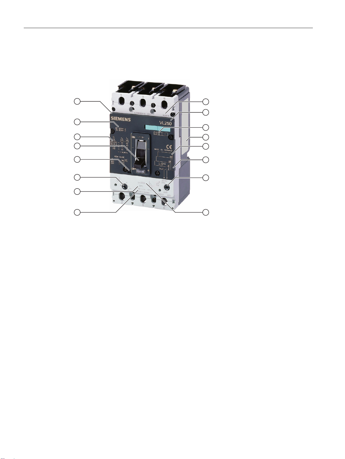
Type plate and ID number
The figure shows all the operator elements, setting options and names corresponding to the
precise specified use of the circuit breaker.
(1) Specified frame size
(2) Circuit breaker type
(3) Display of switching capacity
(4) Rating plate
(5) Accessories ID fields
(6) Catalog number (machine-readable product code)
(7) Overcurrent adjustment
(8) I
rated current of the circuit breaker
n
(9) Overcurrent tripping type TM (thermomagnetic)
(10) Reference temperature
(11) Short-circuit tripping/adjustment
(12) Test key
(13) Toggle handle with 3 positions
(14) Switching capacity
(15) Standards
(16) Accessories cover (removable)
Figure 3-1 SENTRON VL circuit breakers - labeling and operator elements
3VL molded-case circuit breakers
16 System Manual, 03/2009, 110 0110 - 02 DS 01
Product description
3.1 SENTRON VL overview
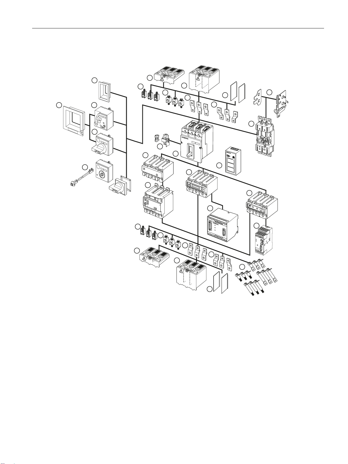
SENTRON VL accessories
(1) Withdrawable/plug-in socket (13) Door-coupling rotary operating mechanism
(2) Withdrawable side panels (14) SENTRON 3VL circuit breaker
(3) Phase barriers (15) Internal accessories
(4) Flared busbar extensions (16) Electronic overcurrent trip unit LCD ETU
(5) Straight connecting bars (17) Electronic overcurrent trip unit with communication function
(6) Multiple feed-in terminal for Al/Cu (18) Thermal/magnetic overcurrent trip unit
(7) Box terminal for Cu (19) RCD module
(8) Extended terminal cover (20) Rear terminals – flat and round
(9) Standard terminal cover (21) COM10 communication module for PROFIBUS-DP
(10) Masking/cover frame for door cutout (22) COM20 communication module for PROFIBUS-DP
(11) Stored-energy motorized operating
(23) Battery power supply with test function
mechanism
(12) Front rotary operating mechanism
Figure 3-2 SENTRON VL accessories
3VL molded-case circuit breakers
System Manual, 03/2009, 110 0110 - 02 DS 01
17
Product description
3.2 Application overview
3.2 Application overview
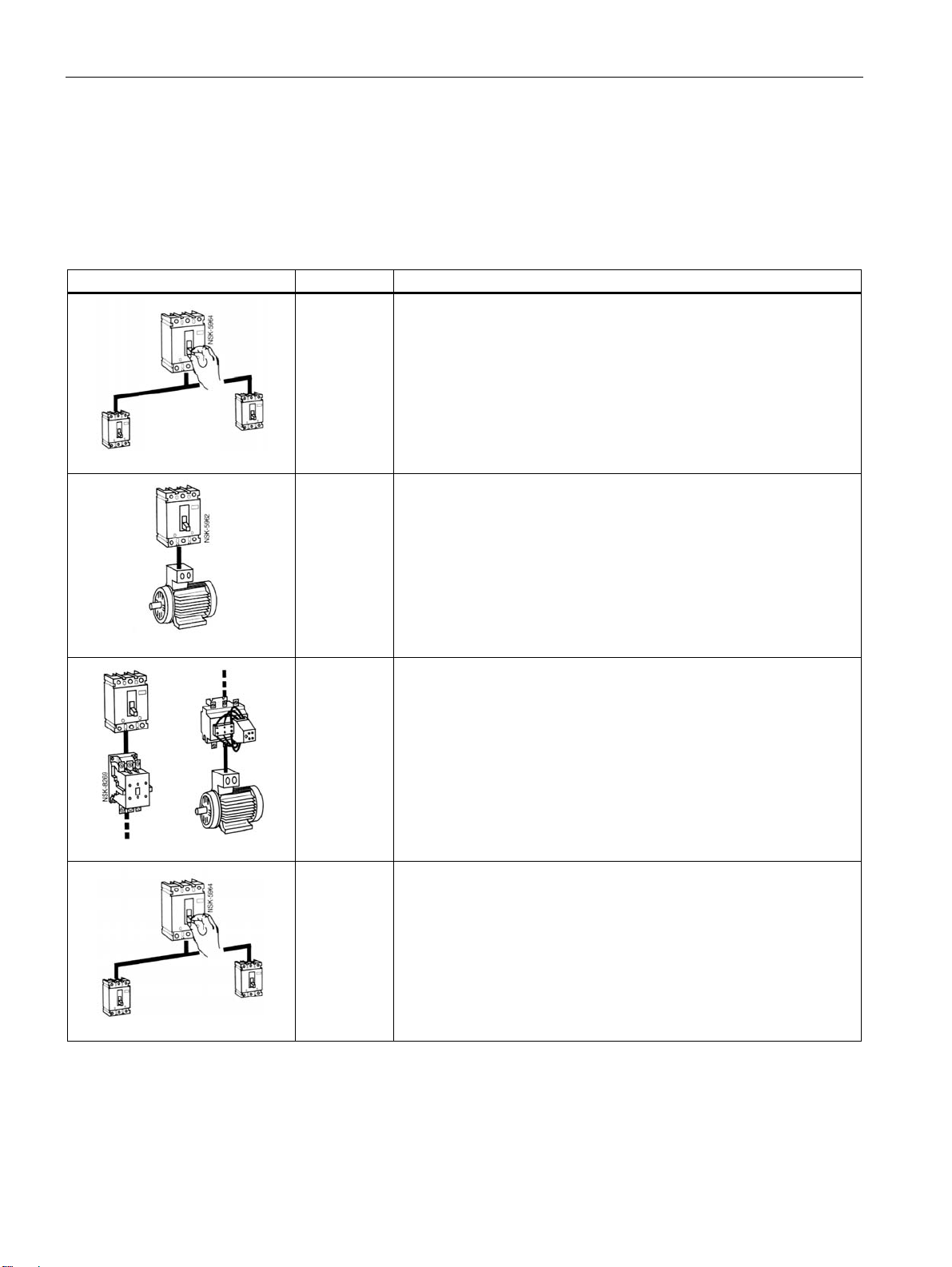
The following overview shows the most frequently occurring applications
Application overview
Application Type Description
Line protection
The trip units for line protection are designed to protect cables and nonmotorized loads against overload and short-circuit.
Motor/generator protection
The overload and short-circuit releases are designed for optimum
protection and direct-online starting of AC squirrel-cage motors. The
circuit breakers for motor protection have phase-failure sensitivity and a
thermal memory that protects the motor against overheating. The
adjustable time lag class enables users to adjust the overload release
to the startup conditions of the motor to be protected.
3- and 4-pole circuit breakers
VL160X
VL160
VL250
VL400
VL630
VL800
VL125
VL1600
VL160
VL250
VL400
VL630
3-pole circuit breaker
3-pole circuit breaker
3- and 4-pole circuit breakers
VL160
VL250
VL400
VL630
VL160X
VL160
VL250
VL400
VL630
VL800
VL1250
VL1600
Starter combination
Starter combinations consist of: Circuit breaker + contactor + overload
relay. The circuit breaker handles short-circuit protection and the
isolating function. The contactor has the task of switching the load
feeder normally. The overload relay handles overload protection that
can be specially matched to the motor. The circuit breaker for starter
combination is therefore equipped with an adjustable and non-delayed
short-circuit release.
Non-automatic air circuit breakers
These circuit breakers are used as incoming circuit breakers, main
switches or isolating switches without overload protection. They have
fixed short-circuit releases so that back-up fuses are not necessary.
3VL molded-case circuit breakers
18 System Manual, 03/2009, 110 0110 - 02 DS 01

Product description
3.3 Configuration
3.3 Configuration
3.3.1 Functional principle
Design - mechanical principle
All SENTRON VL circuit breakers have a trip-free mechanism that ensures the trip process
is not prevented even if the operating mechanism is blocked or manually held in the "ON"
position.
The contacts are opened and closed by a toggle handle positioned in the center. This is
attached to the front side on all circuit breakers.
All SENTRON VL circuit breakers are "joint trip units". This means all contacts open or close
simultaneously when the circuit breaker toggle handle is moved from "OFF" to "ON" or from
"ON" to "OFF", or when the tripping mechanism is activated by an overcurrent or with the
help of an auxiliary trip (shunt release or undervoltage release).
Current limiting
The SENTRON VL circuit breakers are designed on the principle of magnetic repulsion of
the contacts. The contacts open before the expected peak-value of the short-circuit current is
reached. Magnetic repulsion of the contacts very significantly reduces the thermal load I
well as the mechanical load resulting from the impulse short-circuit current I
components that occur during a short-circuit.
You can find more information in Chapter
3.3.2 Subdivision according to power ranges
VL160X circuit breakers
The most important components of the VL160X circuit breakers are the three current paths
with the incoming and outgoing terminals. The fixed and movable contacts are arranged in
such a way as to guarantee magnetic repulsion of the contacts. In conjunction with the arc
splitter chambers, a dynamic impedance is created that causes a current limitation through
the reduction in the harmful effects of I
The overcurrent trip unit is a thermomagnetic device installed at the factory. It is equipped
with fixed or adjustable overload releases and a fixed short-circuit release in each pole.
To the right and left of the centrally positioned toggle handle of every SENTRON VL circuit
breaker is a double-insulated accessories compartment for installing auxiliary switches or
alarm switches as well as voltage and undervoltage releases.
2
of the system
P
Use in the motor protection area (Page 74).
t and the Ip energy resulting from short-circuits.
2
t as
3VL molded-case circuit breakers
System Manual, 03/2009, 110 0110 - 02 DS 01
19

Product description
3.3 Configuration
VL160 to VL630 circuit breakers
The arrangement of current paths, contact configuration and switch mechanism of the VL160
to VL630 circuit breakers corresponds to that of the VL160X circuit breaker. The designs
diverge with regard to the overcurrent trip unit.
● The overcurrent trip units are available in a thermomagnetic version and in an electronic
version.
● The overcurrent trip units can be installed or replaced on-site without special tools.
● Thermomagnetic overcurrent trip units are available with adjustable overload releases
and short-circuit releases.
VL800 bis VL1600 circuit breakers
The arrangement of the current paths and switch mechanisms is identical to that of the
VL160X to VL630 circuit breakers.
However, the VL800 to VL1600 circuit breakers are only available in the version with
electronic overcurrent trip unit. As with all electronic overcurrent trip units for the SENTRON
VL circuit breakers from Siemens, the current transformers (one per phase) are
accommodated within the overcurrent trip unit housing. They transmit a signal proportional to
the load current to the electronic trip unit.
All SENTRON VL circuit breakers with electronic trip units measure the actual effective
current. This method is the most accurate way of measuring currents in electrical distribution
systems with extremely high harmonics.
3.3.3 Thermomagnetic overcurrent trip units
Thermomagnetic overcurrent trip units
A thermomagnetic overcurrent trip unit consists of two components - a thermal release for
protecting against overload, and a magnetic release for protecting against short-circuit. Both
trip unit components are switched in series.
The thermal trip unit
consists of a temperature-dependent bimetal that heats up as a result of the flow of current.
This means the release is current-dependent. The heating of the bimetal strip depends on
the ambient temperature of the circuit breaker. All current values specified for 3VL for
thermomagnetic trip units refer to an ambient temperature of 40°C. Where ambient
temperatures deviate from this, the values in the tables in Chapter
(Page 159) are to be used.
Derating factors
3VL molded-case circuit breakers
20 System Manual, 03/2009, 110 0110 - 02 DS 01

Product description
3.3 Configuration
The magnetic trip unit
comprises a yoke mounting through which a current path runs, and a flap armature that is
kept at a distance from the yoke mounting by a tension spring. If a short-circuit current now
flows along the current path, the magnetic field thus generated causes the flap armature to
be moved towards the yoke mounting against the opposite force of the tension spring. The
release time is almost current-independent and instantaneous. The flap armature releases
the switching lock and thus opens the switching contacts before the short-circuit current can
reach its maximum; a current limiting effect is thus achieved. Immediately after release, the
flap armature is moved back to its starting position by the opposite force of the tension
spring.
3.3.4 Electronic overcurrent trip unit (ETU)
Electronic trip units (ETU)
In contrast to thermomagnetic trip units (TMTUs) where the overcurrent trip is unit caused by
a bimetal strip or magnetic release, electronic overcurrent trip units (ETUs) use electronics
with current transformers. The ETU captures the actual currents and compares them with the
default specifications.
Configuration
All SENTRON 3VL circuit breakers with electronic overcurrent trips measure the actual
effective current (true RMS). This is the most accurate method of measuring.
ETUs are available from the VL160 circuit breaker up to and including the VL1600. The
SENTRON VL800, VL1250 und VL1600 circuit breakers are only available in the version
with electronic overcurrent trip unit.
The trip units can be replaced by the customer without special tools. Replacement is
described precisely in the operating instructions included with the ETUs. After installing the
electronic overcurrent trip unit in the relevant circuit breaker, the battery supply must be
tested with test function 3VL9000-8AP00.
The electronic overcurrent tripping system consists of:
● 3 to 4 (3-pole or 4-pole) current transformers that also provide their own power supply.
This means an external auxiliary voltage is not required.
● Evaluation electronics with microprocessor
● Tripping solenoid
In all versions with electronic trip units for the SENTRON 3VL circuit breakers, the current
transformers are located in the same housing as the trip unit. At the output of the electronic
overcurrent tripping module, there is a tripping solenoid that releases the circuit breaker in
the event of an overload or short-circuit.
3VL molded-case circuit breakers
System Manual, 03/2009, 110 0110 - 02 DS 01
21

Product description
3.3 Configuration
Power supply
The protection functions of the electronic overcurrent trip unit are guaranteed without
additional auxiliary voltage. The overcurrent trip units are supplied with energy via internal
current transformers. The protection function is parameterized via rotary encoding switches
on the ETU or via an LCD display. In the case of an LCD display, the electronic overcurrent
trip unit must be activated. This requires a 3-phase (3-pole) load current of at least 20% or,
in the case of a single-phase (single-pole) load, 30% of the relevant rated current of the
circuit breaker. If this load current is not available, the necessary auxiliary energy can be
supplied via a battery power supply (order no. 3VL9000-8AP00). With communicationcapable circuit breakers, the trip unit is supplied with energy via the COM10/COM20 module.
4-pole circuit breakers
The four-pole circuit breakers for system protection can be supplied in all 4 poles with or
without current transformers. The trip units in the 4th pole (N) can be set to 50% or 100% of
the current in the 3 main current paths dependent on the frame size, so that safe protection
of the neutral conductor can be guaranteed even with a reduced cross-section. In the case of
LCD-ETUs, the neutral conductor protection can be adjusted in steps from 50% to 100% or
switched off.
3VL molded-case circuit breakers
22 System Manual, 03/2009, 110 0110 - 02 DS 01
Product description
3.4 Mechanical operating mechanisms
3.4 Mechanical operating mechanisms
3.4.1 Toggle handle operating mechanism
In the basic version, the SENTRON VL circuit breakers have a toggle handle as an operating
mechanism. This also functions as an indicator of the switching position. The "Tripped"
position is also displayed in addition to the "ON" and "OFF" positions.
The toggle handle goes to the "tripped" position when the internal trip mechanism is
activated by an overcurrent situation, e.g. overload or short-circuit.
Activation by an undervoltage release or shunt release will also cause the toggle handle to
move to the "Tripped" position.
The toggle handle must be returned to the
"OFF/RESET" position before the circuit breaker can be
turned back on again. This enables the internal release
mechanism to be reset. SENTRON VL circuit breakers
with toggle handle operation comply with the "Network
Toggle handle in the "ON"
position
disconnecting device" condition (5.3.2 Section c) and
5.3.3) according to DIN EN 60204-1 (VDE 0113-1).
Toggle handle positions
ON OFF
Toggle handle positions
Tripped
RESET
3VL molded-case circuit breakers
System Manual, 03/2009, 110 0110 - 02 DS 01
23
Product description
3.4 Mechanical operating mechanisms
3.4.2 Rotary mechanism on front (optional)
The rotary mechanism on the front converts the vertical movement of the toggle handle into
rotary motion. The circuit breaker is switched on/off or tripped with the help of the rotary
mechanism on the front. The rotary motion on the switching knob is converted to vertical
motion on the toggle handle.
The rotary mechanism on the front is mounted direct on the circuit
breaker. SENTRON VL circuit breakers with rotary mechanism
comply with the "Network disconnecting device" condition of
DIN EN 60204-1 (VDE 0113-1).
Rotary mechanism
Degree of protection
The rotary mechanism on the front offers degree of protection IP30
Interlocking
Lockable in the "OFF" position with up to 3 padlocks.
A safety lock can also be used.
Application
Standard application:
● Black knob
● Gray indicator plate
Network disconnector facility with features for stopping and shutting down in an emergency:
● Red knob
● Yellow indicator plate
Accessories
Optionally, up to 4 changeover contacts can be used. Two contacts can be used as leading
NO contacts and two contacts as leading NC contacts. These are equipped with 1.5 m long
connection cables.
3VL molded-case circuit breakers
24 System Manual, 03/2009, 110 0110 - 02 DS 01

Product description
3.4 Mechanical operating mechanisms
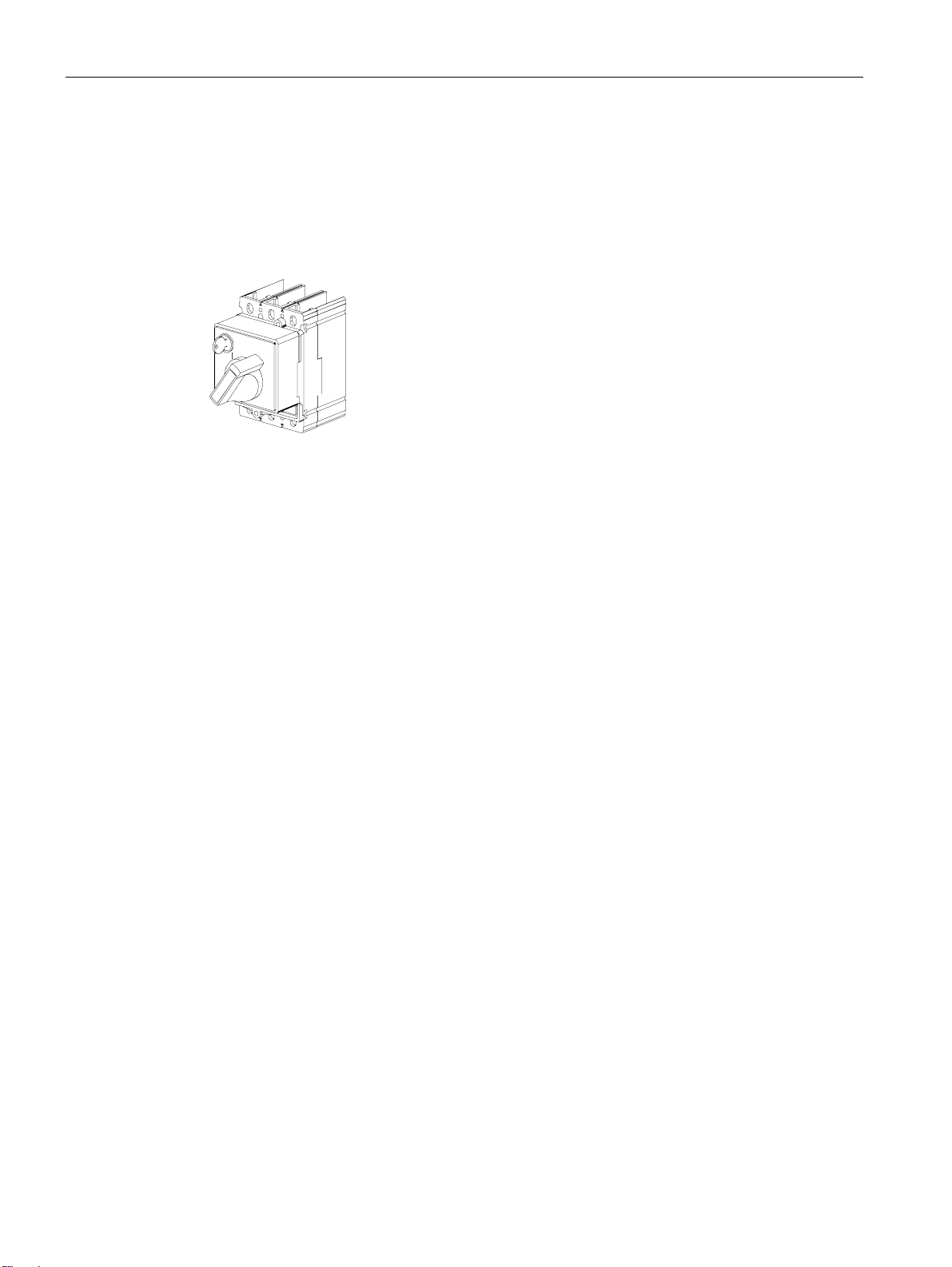
3.4.3 Door-coupling rotary operating mechanism (optional)
The door-coupling rotary operating mechanism is available for installation in control cabinets
and distribution boards.
SENTRON VL circuit breakers with door-coupling rotary
mechanisms comply with the "Network disconnecting
device" condition of DIN EN 60204-1 (VDE 0113-1).
Door-coupling rotary operating
mechanism
The door-coupling rotary operating mechanism is designed as follows:
● Rotary mechanism on the front with shaft stub (without knob)
● Shaft coupling
● 300 mm extension shaft (600 mm optional, clip required)
● Actuator
Degree of protection
This mechanism offers degree of protection IP65
Interlocking
Lockable in the "OFF" position with up to 3 padlocks. A safety lock can also be used.
Application
Standard application:
● Black knob
● Gray indicator plate
Network disconnector facility with features for stopping and shutting down in an emergency:
● Red knob
● Yellow indicator plate
Accessories
Optionally, up to 4 changeover contacts can be used:
Two contacts can be used as leading NO contacts and two contacts as leading NC contacts.
These are equipped with 1.5 m long connection cables
3VL molded-case circuit breakers
System Manual, 03/2009, 110 0110 - 02 DS 01
25
Product description
3.5 Motorized operating mechanisms (optional)
3.5 Motorized operating mechanisms (optional)
Motorized operating mechanisms enable the circuit breaker to be switched on/off locally or
on-site or by remote control. For electrical and mechanical locking of the operating
mechanism, they are equipped with a locking device for padlocks (standard) and an
(optional) safety lock. Motorized operating mechanisms can also be actuated manually. Two
types of mechanisms are offered.
Note
SENTRON circuit breakers with motorized operating mechanisms cannot be used as
network disconnection devices in accordance with DIN EN 60204-1 (VDE 0113-1).
Designation of the connecting cables
Internal terminal strip
Internally wired Externally wired
PE X20.5 Green/yellow
L2- X20.1 N
S2A X20.2 S2A
S2B X20.3 S2B
L1+ X20.4 L1
Identifier
3VL molded-case circuit breakers
26 System Manual, 03/2009, 110 0110 - 02 DS 01

Product description
3.5 Motorized operating mechanisms (optional)
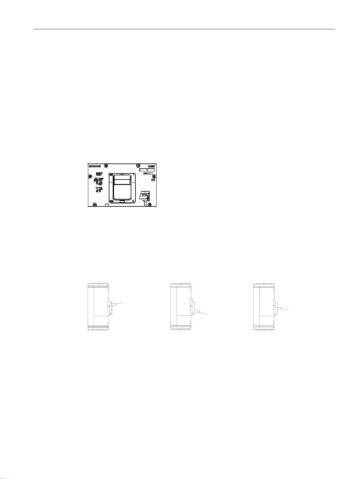
3.5.1 Stored-energy motorized operating mechanism
Motorized operating mechanism for VL160X-VL800
● The stored-energy motorized operating mechanism is suitable for synchronization tasks.
● The motor charges a stored-energy spring mechanism and moves the SENTRON VL
toggle handle to the "OFF/RESET" position.
● The stored-energy spring mechanism discharges when actuated, quickly switching the
SENTRON VL toggle handle to the "ON" position.
● A changeover switch allows local (Manual) or remote (Auto) operation to be selected.
● The manual actuator handle is located on the front of the operating mechanism cover.
Figure 3-3 Stored-energy motorized operating mechanism
3.5.2 Motorized operating mechanism without stored-energy mechanism
Motorized operating mechanism for VL1250-1600
● The motor drives a mechanism that switches the SENTRON VL toggle handle to the "ON"
and "OFF/RESET" positions.
● The manual actuator handle is located on the front of the operating mechanism cover.
3VL molded-case circuit breakers
System Manual, 03/2009, 110 0110 - 02 DS 01
27

Product description
3.5 Motorized operating mechanisms (optional)
3VL molded-case circuit breakers
28 System Manual, 03/2009, 110 0110 - 02 DS 01

System overview
4.1 Possible applications
Thanks to its universal connection and switching configuration, the SENTRON VL circuit
breaker offers a diverse range of possible applications:
Table 4- 1 Possible applications
Area of application Function
Plant
Motor/generator
4
Current limiting
Controller monitoring
Ground-fault protection
Undervoltage protection
Overload protection
Phase-failure protection
Thermodynamic winding protection
Harmonic protection Converter
Frequency-independent load protection
Remote trip units Switch disconnectors
Auxiliary contact/alarm trip unit
3VL molded-case circuit breakers
System Manual, 03/2009, 110 0110 - 02 DS 01
29

System overview
4.2 Key data
4.2 Key data
4.2.1 General data - 3VL molded-case circuit breakers
Type VL160X
3VL1
Max. rated current In [A] 160 160 250 400 630 800 1250 1600
N pole [A] 160 160 250 400 630 800 1250 1600
Rated insulation voltage Vi in accordance with IEC 60947-2
Main current paths [V AC] 800 800 800 800 800 800 800 800
Auxiliary circuits [V AC] 690 690 690 690 690 690 690 690
Rated impulse withstand voltage V
imp
Main current paths [kV] 8 8 8 8 8 8 8 8
Auxiliary circuits [kV] 4 4 4 4 4 4 4 4
Rated operating voltage Ue
IEC 50/60 Hz [V AC] 690 690 690 690 690 690 690 690
IEC 50/60 Hz (V DC2)) 500 600 600 600 600 -1) NEMA 60 Hz (V AC) 600 600 600 600 600 600 600 600
Utilization category
A A A A A
(IEC 60947-2)
Permissible ambient temperature 4)
Operation [°C] -25 to
+70
Storage [°C] -40 to
+80
Permissible load at different ambient temperatures
in the immediate vicinity of the circuit breaker, related to the rated current of the circuit breaker
• Circuit breaker for system protection
VL160
3VL2
-25 to
+70
-40 to
+80
VL250
3VL3
-25 to
+70
-40 to
+80
VL400
VL4
-25 to
+70
-40 to
+80
VL630
3VL5
3)
B
-25 to
+70
-40 to
+80
VL800
VL6
A
B3)
-25 to
+70
-40 to
+80
VL1250
3VL7
1)
-
A
B3)
-25 to
+70
-40 to
+80
VL1600
3VL8
1)
A
B3)
-25 to
+70
-40 to
+80
TM/ETU up to 50 °C [%] 100 /- 100 / 100 100 / 100 100 / 100 100 / 100 - / 100 - / 100 - / 100
TM/ETU up to 60 °C [%] 93 / - 93 / 95 93 / 95 93 / 95 93 / 95 - / 95 - / 95 - / 95
TM/ETU up to 70 °C [%] 86 / - 86 / 80 86 / 80 86 / 80 86 / 80 - / 80 - / 80 - / 80
• Circuit breakers for motor protection
Up to 50 °C [%] - 100 100 100 100 - - -
At 60 °C [%] - 95 95 95 95 - - At 70 °C [%] - 80 80 80 80 - - -
• Circuit breakers for starter combinations and non-automatic air circuit breakers
up to 50 °C [%] 100 100 100 100 100 100 100 100
At 60 °C [%] 93 93 93 93 93 93 93 93
At 70 °C [%] 86 86 86 86 86 86 86 86
3VL molded-case circuit breakers
30 System Manual, 03/2009, 110 0110 - 02 DS 01
 Loading...