

Siemens Sentron 3VA User Manual


SENTRON
Protection devices
3VA molded case circuit breakers
with UL and IEC certification
Manual
01/2019
Introduction
1
Description
2
Applications
3
Accessories
4
Service and maintenance
5
Technical specifications
6
Appendix
A
ESD guidelines
B
List of abbreviations
C
Conversion tables
D
___________________
___________________
___________________
___________________
___________________
___________________
___________________
___________________
___________________
L1V30435333-01
Legal information
Warning notice system
DANGER
will
WARNING
may
CAUTION
NOTICE
Qualified Personnel
personnel qualified
Proper use of Siemens products
WARNING
Trademarks
Disclaimer of Liability
This manual contains notices you have to observe in order to ensure your personal safety, as well as to prevent
damage to property. The notices referring to your personal safety are highlighted in the manual by a safety alert
symbol, notices referring only to property damage have no safety alert symbol. These notices shown below are
graded according to the degree of danger.
indicates that death or severe personal injury
indicates that death or severe personal injury
indicates that minor personal injury can result if proper precautions are not taken.
indicates that property damage can result if proper precautions are not taken.
If more than one degree of danger is present, the warning notice representing the highest degree of danger will
be used. A notice warning of injury to persons with a safety alert symbol may also include a warning relating to
property damage.
result if proper precautions are not taken.
result if proper precautions are not taken.
The product/system described in this documentation may be operated only by
task in accordance with the relevant documentation, in particular its warning notices and safety instructions.
Qualified personnel are those who, based on their training and experience, are capable of identifying risks and
avoiding potential hazards when working with these products/systems.
Note the following:
Siemens products may only be used for the applications described in the catalog and in the relevant technical
documentation. If products and components from other manufacturers are used, these must be recommended
or approved by Siemens. Proper transport, storage, installation, assembly, commissioning, operation and
maintenance are required to ensure that the products operate safely and without any problems. The permissible
ambient conditions must be complied with. The information in the relevant documentation must be observed.
All names identified by ® are registered trademarks of Siemens AG. The remaining trademarks in this publication
may be trademarks whose use by third parties for their own purposes could violate the rights of the owner.
We have reviewed the contents of this publication to ensure consistency with the hardware and software
described. Since variance cannot be precluded entirely, we cannot guarantee full consistency. However, the
information in this publication is reviewed regularly and any necessary corrections are included in subsequent
editions.
for the specific
Siemens AG
Division Energy Management
Postfach 32 20
91050 ERLANGEN
GERMANY
Document order number: 3ZW1012-0VA51-0AC1
Ⓟ 01/2019 Subject to change
Copyright © Siemens AG 2019.
All rights reserved

Table of contents
1 Introduction ............................................................................................................................................. 9
2 Description ............................................................................................................................................ 13
1.1 About this documentation ......................................................................................................... 9
1.2 Product-specific information ................................................................................................... 10
1.2.1 Target readers ........................................................................................................................ 10
1.2.2 Technical Support ................................................................................................................... 10
1.2.3 Reference documents ............................................................................................................. 11
2.1 Overview - applications and portfolio ...................................................................................... 13
2.1.1 Applications and possible uses ............................................................................................... 13
2.1.2 Aspects of the UL market - Low-voltage systems in the USA ................................................ 14
2.1.3 Portfolio ................................................................................................................................... 16
2.1.4 Detailed information about applications and possible uses .................................................... 21
2.1.5 Technical specifications .......................................................................................................... 22
2.1.6 Molded case circuit breakers and accessories in the system ................................................ 26
2.2 Ergonomic design ................................................................................................................... 28
2.2.1 Installation variants for 3VA UL .............................................................................................. 28
2.2.2 Ergonomic design of circuit breakers, handles and control elements .................................... 31
2.2.3 Wide range of accessories ..................................................................................................... 34
2.2.4 Connection technology ........................................................................................................... 36
2.3 Technical details ..................................................................................................................... 38
2.3.1 Circuit breaker identification ................................................................................................... 38
2.3.2 Operation ................................................................................................................................ 47
2.3.3 Current limitation ..................................................................................................................... 48
2.4 Standards and guidelines ....................................................................................................... 50
2.4.1 Compliance with standards and electromagnetic compatibility .............................................. 50
2.4.2 Certificates .............................................................................................................................. 51
2.4.3 Ambient conditions .................................................................................................................. 51
2.4.4 Permissible mounting positions and mounting positions with accessories ............................ 53
2.4.5 Safety clearances (for IEC applications)................................................................................. 54
2.4.6 Breaker venting ....................................................................................................................... 59
2.4.7 Minimum enclosure dimensions ............................................................................................. 60
2.4.8 I
2.4.9 Environmental protection ........................................................................................................ 62
2.5 Protection functions ................................................................................................................ 63
2.5.1 Description of functions........................................................................................................... 64
2.5.2 Characteristic curves .............................................................................................................. 66
2.5.3 Guide to setting the tripping characteristic.............................................................................. 67
2.5.4 Overload protection (L) ........................................................................................................... 68
2.5.5 Short-time delayed short-circuit protection (S) ....................................................................... 69
2.5.6 Instantaneous short-circuit protection (I) ................................................................................ 69
P degrees of protection .......................................................................................................... 61
3VA molded case circuit breakers with UL and IEC certification
Manual, 01/2019, L1V30435333-01
3

Table of contents
3 Applications .......................................................................................................................................... 99
4 Accessories ......................................................................................................................................... 151
2.5.7 Ground-fault protection .......................................................................................................... 70
2.5.7.1 Measurement method 1: Vectorial summation (residual) current .......................................... 70
2.5.7.2 Measurement method 2: Direct detection .............................................................................. 72
2.5.8 Neutral conductor protection (N) ............................................................................................ 73
2.5.9 Zone-selective interlocking ZSI .............................................................................................. 76
2.6 Thermal-magnetic trip unit ..................................................................................................... 79
2.6.1 Thermal-magnetic trip unit (TMTU) ........................................................................................ 79
2.6.2 Application cases and trip unit types...................................................................................... 79
2.7 Electronic trip unit................................................................................................................... 80
2.7.1 Electronic trip unit (ETU) ........................................................................................................ 80
2.7.2 Connections ........................................................................................................................... 81
2.7.3 Arc energy reduction .............................................................................................................. 81
2.7.4 Protection functions ............................................................................................................... 83
2.7.5 Operator controls ................................................................................................................... 84
2.7.6 Load acceptance and load shedding - load management ..................................................... 94
2.7.7 Measuring with a Rogowski coil ............................................................................................. 95
3.1 Use of the 3VA UL molded case circuit breakers in line protection ....................................... 99
3.1.1 Applications in line protection ................................................................................................ 99
3.1.2 Versions of the trip units ...................................................................................................... 102
3.1.2.1 Thermal-magnetic trip units ................................................................................................. 102
3.1.2.2 Electronic trip units ............................................................................................................... 105
3.1.3 Overview of 3VA UL molded case circuit breakers in line protection .................................. 132
3.2 Use as Motor Circuit Protector (MCP) for starter combinations .......................................... 134
3.3 Use of the 3VA UL molded case circuit breaker as a molded case switch (MCS) .............. 138
3.3.1 Compatibility of 3VA UL molded case switch and accessories ........................................... 140
3.4 Use of 3VA UL molded case circuit breaker in DC systems ................................................ 141
3.4.1 Introduction .......................................................................................................................... 141
3.4.2 Variants ................................................................................................................................ 142
3.4.3 Breaking capacity with direct current ................................................................................... 143
3.4.4 Recommended circuits for DC systems UL ......................................................................... 144
3.4.5 Recommended circuits for DC systems IEC ........................................................................ 146
3.5 Use of 3VA UL molded case circuit breakers in IT systems according to IEC 60947-2 ...... 148
3.5.1 Introduction .......................................................................................................................... 148
3.5.2 Selection criteria for 3VA UL molded case circuit breakers ................................................. 148
3.5.3 Fault situation ....................................................................................................................... 149
4.1 Overview - Accessories for 3VA UL molded case circuit breakers ...................................... 151
4.2 Internal accessories ............................................................................................................. 152
4.2.1 Mounting locations of 3VA UL molded case circuit breakers .............................................. 152
4.2.2 Auxiliary and alarm switches ................................................................................................ 156
4.2.3 Contact sequence diagrams ................................................................................................ 159
4.2.4 Technical specifications of auxiliary and alarm switches ..................................................... 160
4.2.5 Auxiliary releases ................................................................................................................. 162
4.2.6 Time-delay devices for undervoltage releases .................................................................... 166
4.2.7 COM060 communication module......................................................................................... 166
4.2.8 24 V module ......................................................................................................................... 167
3VA molded case circuit breakers with UL and IEC certification
4 Manual, 01/2019, L1V30435333-01

Table of contents
4.3 Connection system ............................................................................................................... 168
4.3.1 Introduction ........................................................................................................................... 168
4.3.2 General information about cables and busbars .................................................................... 168
4.3.3 Connection portfolio for 3VA UL molded case circuit breakers ............................................ 172
4.3.3.1 General overview .................................................................................................................. 172
4.3.3.2 Front cable connection.......................................................................................................... 176
4.3.3.3 Front busbar and compression lug connections ................................................................... 191
4.3.3.4 Rear busbar and compression lug connections ................................................................... 198
4.3.4 Further connection accessories ............................................................................................ 203
4.3.4.1 Insulating equipment ............................................................................................................. 203
4.3.4.2 Control wire tap ..................................................................................................................... 219
4.4 Plug-in and draw-out technology .......................................................................................... 221
4.4.1 Introduction ........................................................................................................................... 221
4.4.2 Overview of variants / products ............................................................................................ 224
4.4.3 General information .............................................................................................................. 225
4.4.4 Information about installation, built-on and built-in components .......................................... 226
4.4.5 Plug-in technology ................................................................................................................ 227
4.4.5.1 Product description ............................................................................................................... 227
4.4.5.2 Combination with other accessories ..................................................................................... 233
4.4.6 Draw-out technology ............................................................................................................. 234
4.4.6.1 Product description ............................................................................................................... 234
4.4.6.2 Combination with other accessories ..................................................................................... 243
4.4.7 Accessories for plug-in and draw-out units ...........................................................................
4
.4.7.1 Description of individual product variants ............................................................................. 244
244
4.4.7.2 Overview of technical specifications ..................................................................................... 256
4.4.7.3 Combination with other accessories ..................................................................................... 257
4.5 Manual operators .................................................................................................................. 258
4.5.1 Introduction ........................................................................................................................... 258
4.5.2 Operator control of the 3VA UL molded case circuit breakers with manual operators ......... 259
4.5.3 Front mounted rotary operator .............................................................................................. 264
4.5.3.1 Elements of the front mounted rotary operator ..................................................................... 264
4.5.3.2 Front mounted rotary operator with door interlock ................................................................ 265
4.5.3.3 Testing the tripping mechanism ............................................................................................ 267
4.5.3.4 Locking, blocking and interlocking ........................................................................................ 268
4.5.4 Door mounted rotary operator .............................................................................................. 271
4.5.4.1 Elements of the door mounted rotary operator ..................................................................... 271
4.5.4.2 Door interlock with door mounted rotary operator ................................................................ 272
4.5.4.3 Tolerance compensator ........................................................................................................ 274
4.5.4.4 Testing the tripping mechanism ............................................................................................ 275
4.5.4.5 Supplementary handle for door mounted rotary operator..................................................... 276
4.5.4.6 Variable depth adapter.......................................................................................................... 277
4.5.4.7 Locking, blocking and interlocking ........................................................................................ 278
4.5.5 Side wall mounted rotary operator ........................................................................................ 281
4.5.5.1 Elements of the side wall mounted rotary operator .............................................................. 281
4.5.5.2 Side wall mounted rotary operator with mounting plate ........................................................
4
.5.5.3 Locking, blocking and interlocking ........................................................................................ 283
282
4.5.6 Operator kit with Bowden cable (Max-Flex operator) ........................................................... 286
4.5.6.1 Elements of the operator kit with Bowden cable ...................................................................
.5.6.2 Door interlocking with the operator kit with Bowden cable ................................................... 287
4
286
4.5.6.3 Testing the tripping mechanism ............................................................................................ 289
4.5.6.4 Auxiliary switches for the operator kit with Bowden cable .................................................... 289
3VA molded case circuit breakers with UL and IEC certification
Manual, 01/2019, L1V30435333-01
5

Table of contents
4.5.6.5 Locking, blocking and interlocking ....................................................................................... 290
4.5.7 Degree of protection ............................................................................................................ 291
4.5.7.1 IP degree of protection ......................................................................................................... 291
4.5.7.2 NEMA degree of protection .................................................................................................. 291
4.5.8 Accessories .......................................................................................................................... 292
4.5.8.1 Illumination kit ...................................................................................................................... 292
4.6 Motor operator...................................................................................................................... 293
4.6.1 Elements of the motor operator MO320 .............................................................................. 293
4.6.2 Description of front panel ..................................................................................................... 294
4.6.3 MANUAL, AUTO and LOCK modes .................................................................................... 295
4.6.4 Operating the molded case circuit breaker with motor operator .......................................... 296
4.6.5 Faults, causes of faults and rectification of faults ................................................................ 300
4.6.6 Technical specifications ....................................................................................................... 301
4.7 Locking and interlocking ...................................................................................................... 302
4.7.1 General information ............................................................................................................. 302
4.7.1.1 General information ............................................................................................................. 302
4.7.1.2 Locking ................................................................................................................................. 302
4.7.1.3 Interlocking ........................................................................................................................... 303
4.7.2 Blocking and locking ............................................................................................................ 305
4.7.2.1 Handle blocking device ........................................................................................................ 305
4.7.2.2 Cylinder locks for locking the 3VA molded case circuit breaker .......................................... 307
4.7.3 Front interlocking.................................................................................................................. 311
4.7.3.1 Cylinder locks for interlocking multiple 3VA UL molded case circuit breakers .................... 311
4.7.3.2 Cable interlock module using a Bowden cable ....................................................................
.7.3.3 Sliding bar ............................................................................................................................ 319
4
316
4.7.4 Rear interlock ....................................................................................................................... 321
4.8 Communication and system integration ............................................................................... 327
4.8.1 System description ............................................................................................................... 327
4.8.2 Communication system of the 3VA UL molded case circuit breaker ................................... 327
4.8.3 COM800 / COM100 breaker data server ............................................................................. 329
4.8.3.1 Area of application ............................................................................................................... 331
4.8.3.2 Features ............................................................................................................................... 331
4.8.4 Communication with ETUs ................................................................................................... 331
4.8.4.1 Area of application ............................................................................................................... 332
4.8.5 DSP800 display.................................................................................................................... 332
4.8.6 Commissioning and testing of electronic trip units using powerconfig ................................ 333
4.8.7 Power management with powermanager ............................................................................ 337
4.9 EFB300 external function box .............................................................................................. 338
4.9.1 General information ............................................................................................................. 338
4.9.2 Power supply ........................................................................................................................ 339
4.9.3 Functions of the digital input and digital outputs .................................................................. 339
4.9.4 Zone-selective interlocking ZSI ............................................................................................ 340
4.9.5 <SET> button ....................................................................................................................... 342
4.9.6 Technical specifications ....................................................................................................... 349
4.10 MMB300 maintenance mode box ........................................................................................
10.1 Operating principle of the MMB300 maintenance mode box ............................................... 351
4.
351
4.10.2 Configuration of MMB300 with a 3VA6 molded case circuit breaker ................................... 353
4.10.3 <SET> button ....................................................................................................................... 357
4.10.4 Power supply ........................................................................................................................
10.5 Technical specifications ....................................................................................................... 358
4.
358
3VA molded case circuit breakers with UL and IEC certification
6 Manual, 01/2019, L1V30435333-01

Table of contents
5 Service and maintenance .................................................................................................................... 381
6 Technical specifications ...................................................................................................................... 385
4.11 Test devices .......................................................................................................................... 360
4.11.1 Introduction ........................................................................................................................... 360
4.11.2 The TD300 activation and trip box ........................................................................................ 361
4.11.2.1 Operation and execution of the tripping function .................................................................. 362
4.11.2.2 Technical specifications of TD300 ........................................................................................ 364
4.11.3 The TD500 test device .......................................................................................................... 364
4.11.3.1 General information, preparations ........................................................................................ 364
4.11.3.2 Operation and execution of test functions ............................................................................ 369
4.11.3.3 Executing the test functions using a PC and powerconfig .................................................... 374
4.11.3.4 Parameterizing using the powerconfig software ................................................................... 374
4.11.3.5 Technical specifications ........................................................................................................ 375
4.12 External current transformer for N conductor ....................................................................... 376
4.13 Cover frame .......................................................................................................................... 378
4.13.1 Product description ............................................................................................................... 378
4.13.2 Labeling plate ........................................................................................................................ 380
5.1 Notes ..................................................................................................................................... 381
5.2 Regular maintenance ............................................................................................................ 382
5.3 Maintenance following tripping of a molded case circuit breaker ......................................... 383
5.4 Fault diagnostics ................................................................................................................... 384
6.1 Circuit diagrams .................................................................................................................... 385
6.1.1 3VA5 molded case circuit breakers ...................................................................................... 385
6.1.1.1 Basic units ............................................................................................................................. 385
6.1.1.2 Accessories ........................................................................................................................... 387
6.1.1.3 Example: 3VA5 molded case circuit breakers with accessories (external/internal) ............. 390
6.1.2 3VA6 molded case circuit breakers ...................................................................................... 391
6.1.2.1 Basic units ............................................................................................................................. 391
6.1.2.2 Accessories ........................................................................................................................... 392
6.1.2.3 Example: 3VA6 molded case circuit breakers with accessories (external/internal) ............. 402
6.1.3 Application example: Electrical interlocking of two 3VA UL molded case circuit
breakers with undervoltage releases .................................................................................... 403
6.2 Dimensional drawings ........................................................................................................... 404
6.2.1 Dimensions of basic units ..................................................................................................... 404
6.2.1.1 3VA51 ................................................................................................................................... 404
6.2.1.2 3VA52 ................................................................................................................................... 406
6.2.1.3 3VA61 / 3VA62 ..................................................................................................................... 407
6.2.1.4 3VA63 / 3VA64 ..................................................................................................................... 408
6.2.2 Dimensions of accessories ................................................................................................... 409
6.2.2.1 Connection technology ......................................................................................................... 409
6.2.2.2 Plug-in and draw-out units .................................................................................................... 416
6.2.2.3 Manual operators .................................................................................................................. 425
6.2.2.4 Motor operators ..................................................................................................................... 439
6.2.2.5 Locking and interlocking ....................................................................................................... 440
6.2.2.6 Communication and system integration................................................................................ 447
6.2.2.7 EFB300 external function box ...............................................................................................
6
.2.2.8 MMB300 maintenance mode box ......................................................................................... 448
448
3VA molded case circuit breakers with UL and IEC certification
Manual, 01/2019, L1V30435333-01
7

Table of contents
A Appendix ............................................................................................................................................. 465
B ESD guidelines .................................................................................................................................... 467
C List of abbreviations ............................................................................................................................. 469
D Conversion tables ................................................................................................................................ 475
Glossary .............................................................................................................................................. 479
Index ................................................................................................................................................... 485
6.2.2.9 Test devices ......................................................................................................................... 449
6.2.2.10 Door cover frame ................................................................................................................. 449
6.3 Power losses ........................................................................................................................ 450
6.3.1 Power losses of 3VA5 molded case circuit breakers ........................................................... 450
6.3.2 Power losses of 3VA6 molded case circuit breakers ........................................................... 452
6.3.3 Power loses of 3VA UL molded case switches .................................................................... 453
6.4 Derating ................................................................................................................................ 454
6.4.1 Derating of 3VA5 molded case circuit breakers ................................................................... 454
6.4.2 Use of terminals with control wire tap .................................................................................. 456
6.4.3 Additional correction factors with frequencies other than 50/60 Hz for 3VA5 molded
case circuit breakers ............................................................................................................ 457
6.4.4 Derating for the electronic trip units of 3VA6 molded case circuit breakers ........................ 458
A.1 Standards and approvals ..................................................................................................... 465
B.1 Electrostatic sensitive devices (ESD) .................................................................................. 467
C.1 Table of abbreviations .......................................................................................................... 469
D.1 Conversion tables ................................................................................................................ 475
3VA molded case circuit breakers with UL and IEC certification
8 Manual, 01/2019, L1V30435333-01

1
1.1
About this documentation
3VA molded case circuit breakers with UL 489 certification for the North American market
The 3VA molded case circuit breakers from the portfolio of SENTRON protection, switching,
measuring and monitoring devices ensure the reliable protection of people and property as
integral components of efficient power distribution systems.
For global applications, a special product portfolio has been developed that has the required
approvals according to standards UL 489 as well as IEC 60947. 3VA molded case circuit
breakers certified to UL 489 are suitable for the following applications:
● Incoming circuit breakers (feeders) and outgoing circuit breakers (branches) in
distribution systems
● Switching and protection devices for motors (motor protection in combination with a
contactor and motor protection relay), transformers and capacitors
● Disconnecting means with features for stopping and switching off in an emergency (main
disconnecting means and EMERGENCY-OFF switches) in conjunction with lockable
rotary operators.
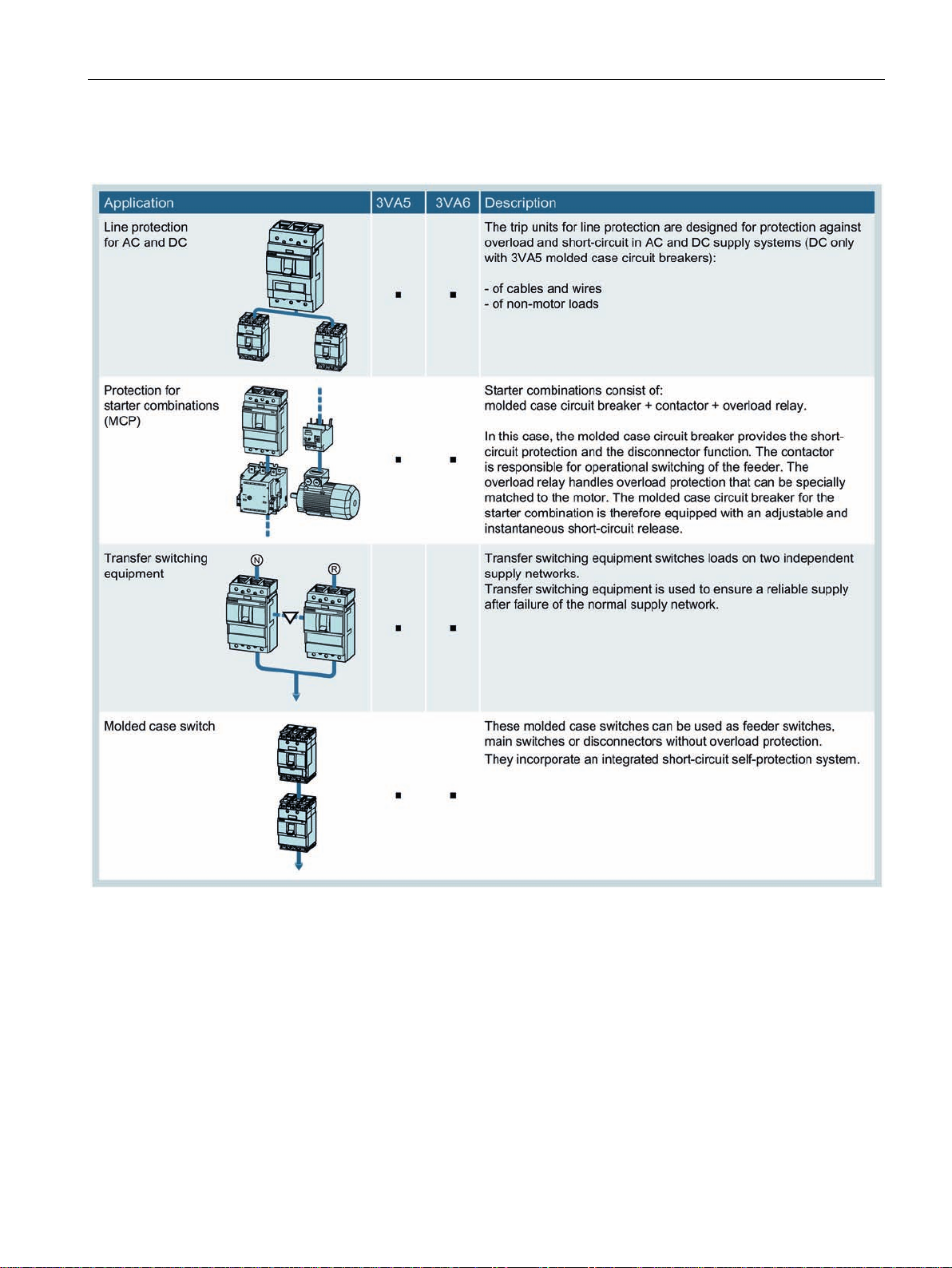
The 3VA molded case circuit breakers certified to UL are available in the following versions:
1. For line protection:
The overload and short-circuit releases are designed for the protection of wiring and nonmotor loads.
2. For starter combinations:
These instantaneous trip circuit breakers are used for short-circuit protection as well as
for the disconnector function, which may be required in Combination Motor Controllers
consisting of instantaneous trip circuit breaker, overload relay and motor contactor.
These instantaneous trip circuit breakers are all equipped with adjustable, instantaneous
short-circuit releases.
3. As molded case switches:
These molded case switches can be used as feeder switches, main switches or nonautomatic circuit breakers without overload protection. They incorporate an integrated
short-circuit self-protection system.
3VA molded case circuit breakers with UL and IEC certification
Manual, 01/2019, L1V30435333-01
9

Introduction
Scope of validity of this document
1.2
Product-specific information
1.2.1
Target readers
Target readers of this documentation
1.2.2
Technical Support
1.2 Product-specific information
This manual has been specially compiled for the 3VA molded case circuit breakers certified
to UL 489, or 3VA UL for short.
The accessories of the 3VA UL molded case circuit breakers are also described in this
manual.
This manual serves as a reference manual for technical information regarding the
configuration, commissioning and operation of 3VA UL molded case circuit breakers and
corresponding accessories.
This manual does not purport to cover all details or variations in equipment, or to provide for
every possible contingency in connection with installation, operation, or maintenance. Should
additional information be desired, please refer to the individual product instruction sheets or
contact the local Siemens sales office.
The contents of this manual shall not become part of or modify any prior or existing
agreement, commitment, or relationship. The sales contract contains the entire obligation of
Siemens. The warranty contained in the contract between the parties is the sole warranty of
Siemens. Any statements contained herein do not create new warranties or modify the
existing warranty.
The information contained in this manual is provided for the benefit of:
● Users
● Control panel manufacturers
● Switchboard manufacturers
● Maintenance personnel
You can find further support on the Internet at:
Technical Support (http://www.siemens.com/lowvoltage/technical-support
)
3VA molded case circuit breakers with UL and IEC certification
10 Manual, 01/2019, L1V30435333-01
Introduction
1.2.3
Reference documents
Further documents
Title
Article number
Link
1.2 Product-specific information
You will find further information in the following documents:
Table 1- 1 Reference documents
3VA IEC Molded Case Circuit Breakers
manual
3VA UL Molded Case Circuit Breakers
catalog (for the European-supported
markets)
3VA UL Molded Case Circuit Breakers
operating instructions
3VA Communication system manual DE 3ZW1012-0VA20-0BB0 3VA molded case circuit breakers
Automatic transfer control device
ATC5300 - Manual
ATSE - Remote Control Software Manual DE A5E02469028-01 ATSE - Remote Control Software Manual
ATSE - Modbus Communication Protocol DE A5E02469001-01 ATSE - Modbus Communication Protocol
Grundlagen der Niederspannungsschalttechnik (Fundamentals of Low-Voltage
Switchgear and Controlgear), Siemens
AG © 2008
Hartmut Kiank, Wolfgang Fruth:
Planungsleitfaden für Energieverteilungsanlagen (Planning Guide for Power
Distribution Plants),
Publicis Publishing
Schalten, Schützen, Verteilen in
Niederspannungsnetzen (Switching,
Protection and Distribution in LowVoltage Networks), substantially extended and revised edition 1997
DE 3ZW1012-0VA10-0AB1 3VA molded case circuit breakers
EN 3ZW1012-0VA10-0AC1
DE E86060-K8290-A101-A1 3VA UL Molded Case Circuit Breakers
EN E86060-K8290-A101-A1-7600
3VA UL Molded Case Circuit Breakers
EN 3ZW1012-0VA20-0BC0
DE A5E02469034-01 ATC5300 automatic transfer control
EN A5E02469035-01
EN
EN
— —
ISBN: A19100-L531-B115 —
ISBN 3-89578-041-3 —
documentation
(https://support.industry.siemens.com/cs/
ww/en/view/90318775)
catalog
(https://support.industry.siemens.com/cs/
ww/en/view/109744301)
operating instructions
(https://support.industry.siemens.com/cs/
ww/en/ps/man)
documentation
(https://support.industry.siemens.com/cs/
ww/en/view/98746267)
device
(http://support.automation.siemens.com/
WW/view/de/41909986/0/en)
http://support.automation.siemens.com/
(
WW/view/en/41909978)
(
http://support.automation.siemens.com/
WW/view/en/40761679)
3VA molded case circuit breakers with UL and IEC certification
Manual, 01/2019, L1V30435333-01
11

Introduction
1.2 Product-specific information
3VA molded case circuit breakers with UL and IEC certification
12 Manual, 01/2019, L1V30435333-01

2
2.1
Overview - applications and portfolio
2.1.1
Applications and possible uses
This chapter provides an overview of all 3VA molded case circuit breakers with certification
according to the North American standard UL 489 (3VA UL) and shows the areas in which
the various molded case circuit breakers are used.
The topics discussed in this chapter are listed below:
● Applications and possible uses
● Aspects of the UL market - Low-voltage systems in the USA
● Portfolio
● Possible configurations
● Detailed information about applications and possible uses
● Technical specifications
● Molded case circuit breakers and accessories in the system
The 3VA UL molded case circuit breakers can be used in various areas in infrastructure,
industry or residential and commercial buildings where they perform different protection
tasks.
Portions of this manual are intended to familiarize customers and users residing outside the
North American market, who may build and export panels, with some of the unique aspects
of UL Certified applications. This range of applications is very diverse, and they are typically
solutions for industry.
Applications in infrastructure and buildings in the North American market are generally
directly supported from within the respective regions.
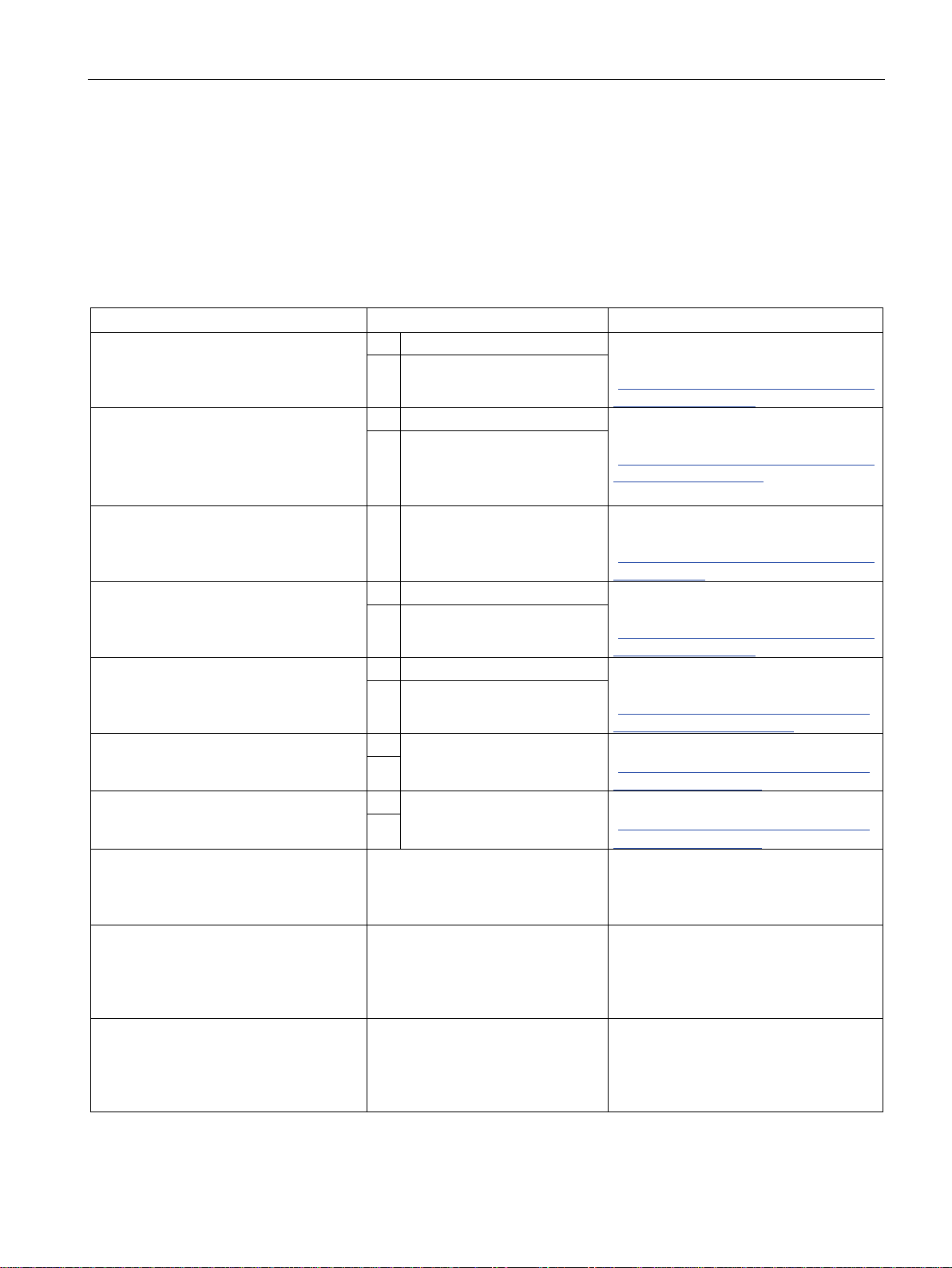
The 3VA UL molded case circuit breakers are used for various functions as shown in the
following table:
3VA molded case circuit breakers with UL and IEC certification
Manual, 01/2019, L1V30435333-01
13

Description
2.1.2
Aspects of the UL market - Low-voltage systems in the USA
Low-voltage systems in the USA
2.1 Overview - applications and portfolio
This chapter is an excerpt from the document "The secrets of UL". You will find the complete
document under
http://w3app.siemens.com/mcms/infocenter/dokumentencenter/ce/Documentsu20Brochures
(
/e20001-a820-p305-v2-7600.pdf).
The usual system configurations in the USA are very different from those found in Europe.
Unlike in the IEC, there is a corner-grounded delta system in addition to the solidly grounded
wye system, which is very similar to the TN-S system. In the USA / UL / NEC, all voltages
that occur in the respective system configuration are always specified (see table below).
When devices are selected, very close attention must be paid to which system configuration
is present at the location of use and the system configuration for which the individual devices
are approved.
The main configurations in industry and in non-residential buildings are 3-phase networks
with 240 V and 480 V, as well as 3- and 4-conductor systems with 480Y/277 V. In residential
buildings and in office spaces of industrial and non-residential buildings, the single-phase
system with 120/240 V can also be commonly found.
1)
Y describes the "Solidly grounded circuit". The value "Y" indicates the voltage between the
phases (e.g. 480 V), and the value behind the slash indicates the voltage between the phase and
the grounding or the neutral conductor (e.g. 277 V with 480 V voltage between the phases).
3VA molded case circuit breakers with UL and IEC certification
14 Manual, 01/2019, L1V30435333-01
Description
Electric circuits with "straight" and "slash" voltages
Short circuit current rating of the control panel main (power) circuit
2.1 Overview - applications and portfolio
In the USA, voltages are considered from the power supply company side or the secondary
side of the power supply company transformers. The connection (wye or delta) of the electric
circuit and the method of grounding play a major role here.
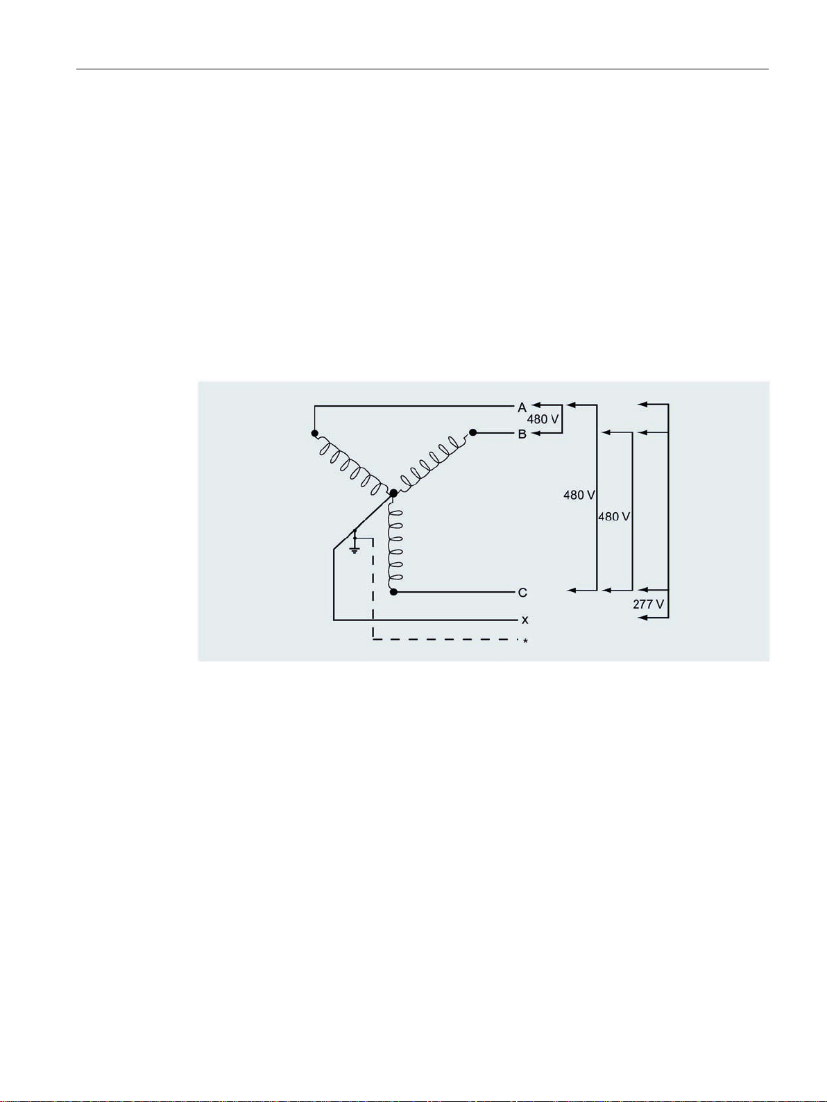
In electric circuits with a Grounded Wye, the circuit breaker only switches the full voltage
between the phases (e.g. 480 V). The phase-to-ground voltage is only 277 V in this case,
which explains the "slash" voltage of 480Y/277 V. Industrial Control Panels in which these
devices are installed must be marked with the following inscription: "For use on a solidly
grounded wye source only" (UL 508A Art. 54.12).
In ungrounded or high-resistance grounded wye or delta circuits, and in corner-grounded
delta circuits, only devices (e.g. circuit breakers) that are labeled with a "straight" voltage,
such as 240 V, 480 V or 600 V, may be used. These devices must be able to switch the full
voltage between the phases and between one phase to ground.
Grounded wye, 480Y / 277 V, 3 phase, 4 wire
An industrial control panel must be marked with a short-circuit current rating (SCCR). In IEC
terms, this corresponds approximately to the I
describes the specifications of the short circuit current rating markings on industrial control
panels (with reference to UL 508A, SB4). For the short circuit current rating, not only is the
short-circuit breaking capacity (e.g. of the circuit breaker) relevant, but also the short-circuit
current rating of each individual device. The SCCR-relevant components in the main circuit
include circuit breakers, contactors, overload relays, and solid-state switching devices, as
well as terminals, busbars, the line side of control transformers and frequency converters,
but not the internal wiring of the control panel.
The lowest value applies to the entire control panel. A short-circuit current higher than this
must not be available at the input terminals of the control panel.
3VA molded case circuit breakers with UL and IEC certification
Manual, 01/2019, L1V30435333-01
value of the panel. NEC 2017 Article 409
cw
15
Description
2.1.3
Portfolio
Sizes
2.1 Overview - applications and portfolio
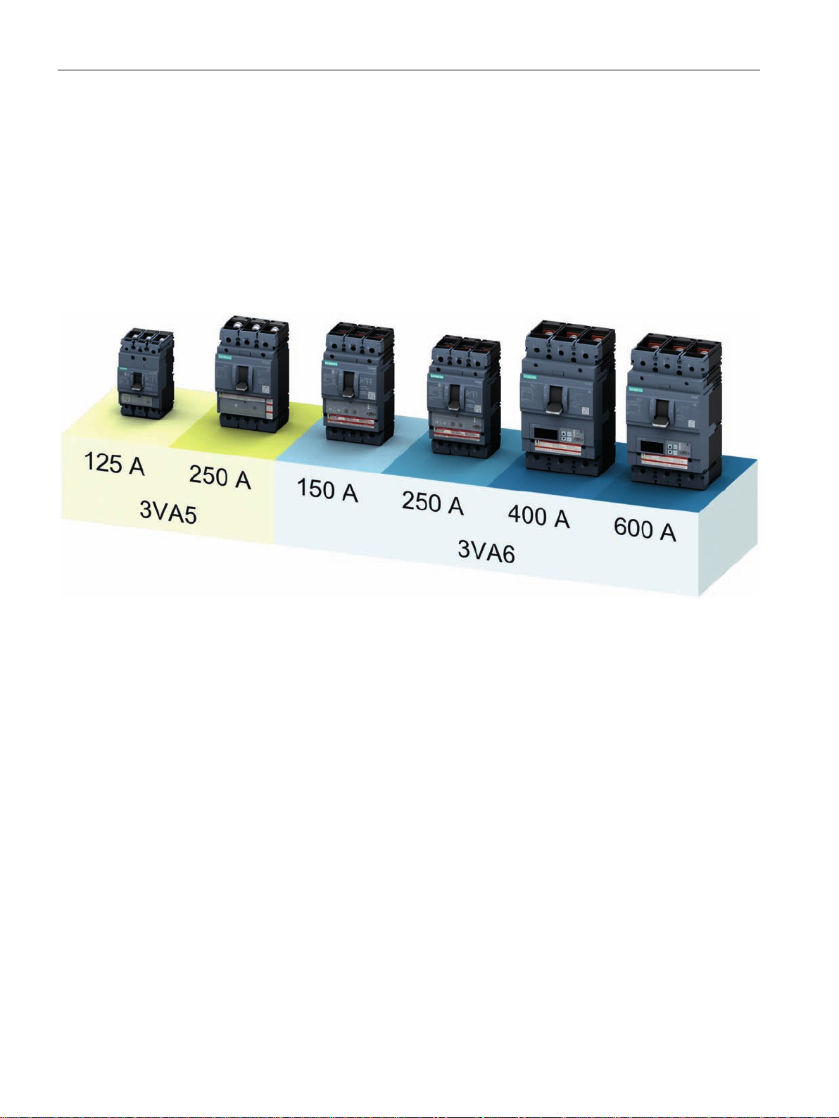
The integrated 3VA UL portfolio consists of two different ranges of molded case circuit
breakers in five different rated operational current versions (frame sizes).
The new 3VA UL molded case circuit breakers set new standards in flexibility and the variety
of modular accessories available. Standardized accessories suitable for use with several
sizes of circuit breaker from all the 3VA UL ranges help to cut costs and save time.
The new 3VA UL molded case circuit breakers are available in the following ranges:
● 3VA5 with thermal-magnetic trip units
● 3VA6 with electronic trip units
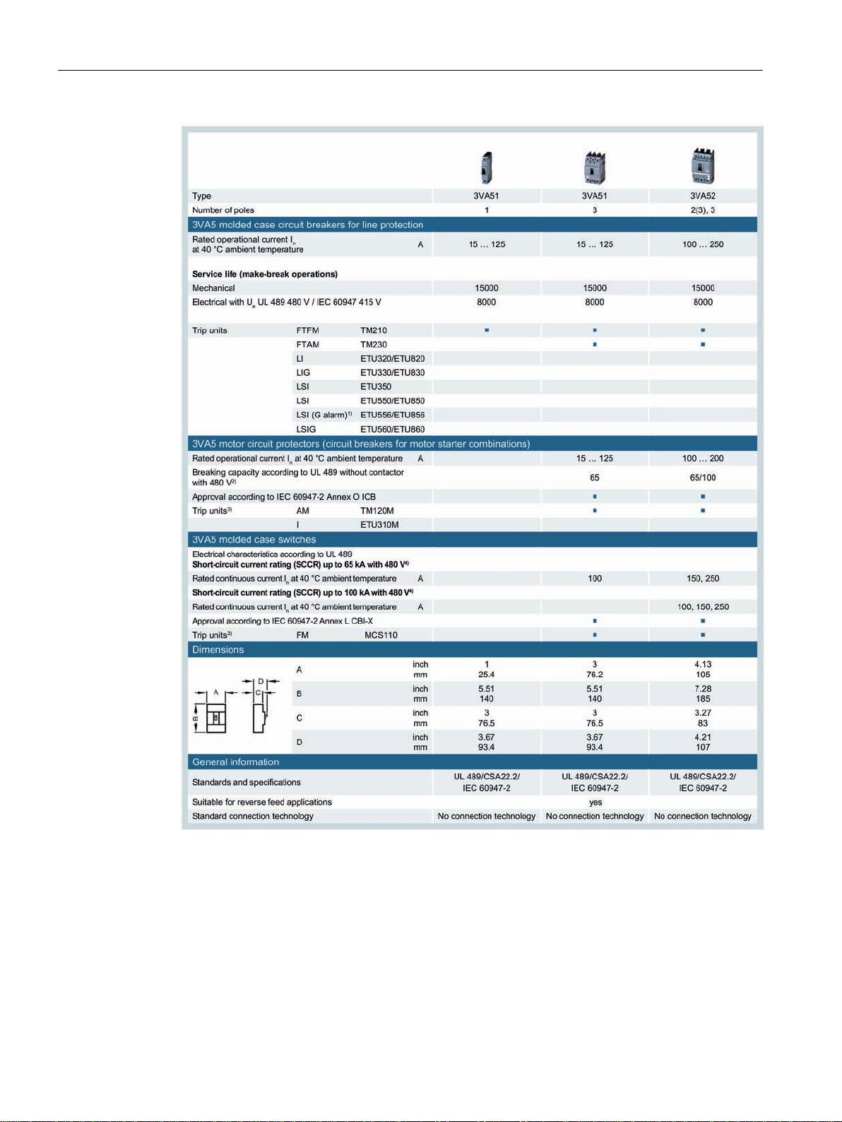
The 3VA5 molded case circuit breakers are available in the following versions:
● 1- and 3-pole version in size up to 125 A (3VA51)
● 2(3)-pole and 3-pole version in size up to 250 A (3VA52)
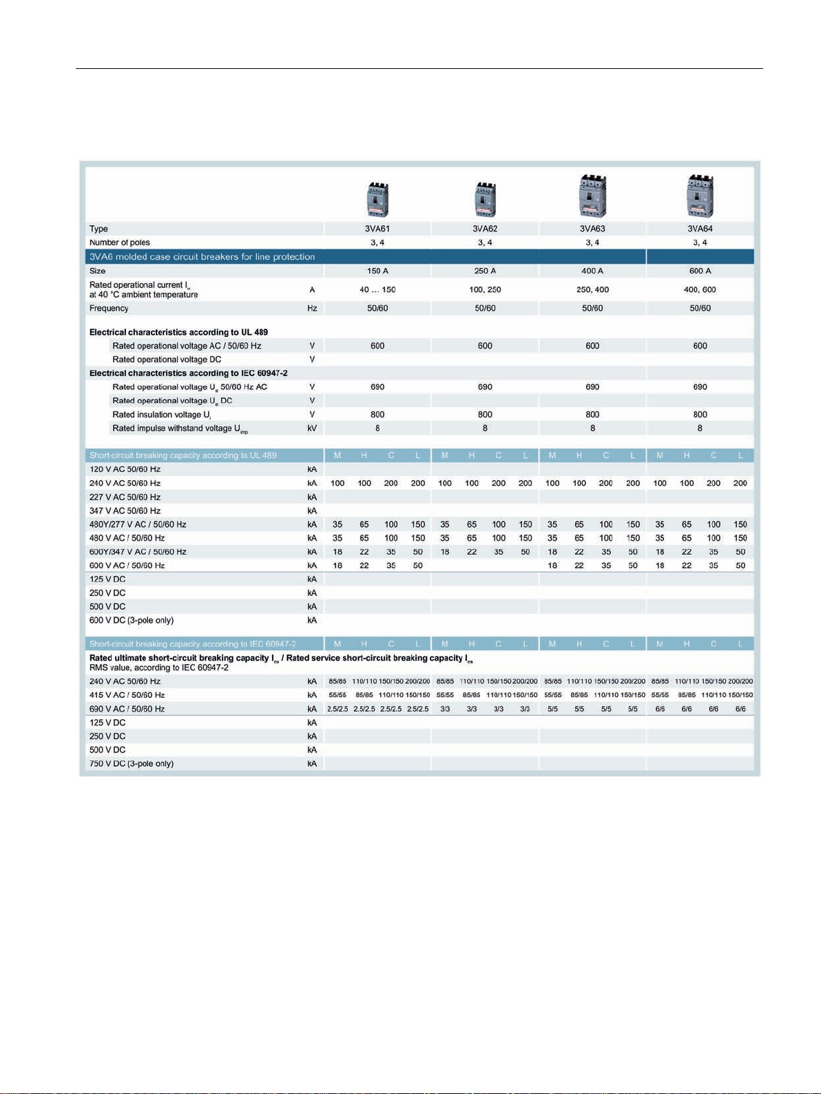
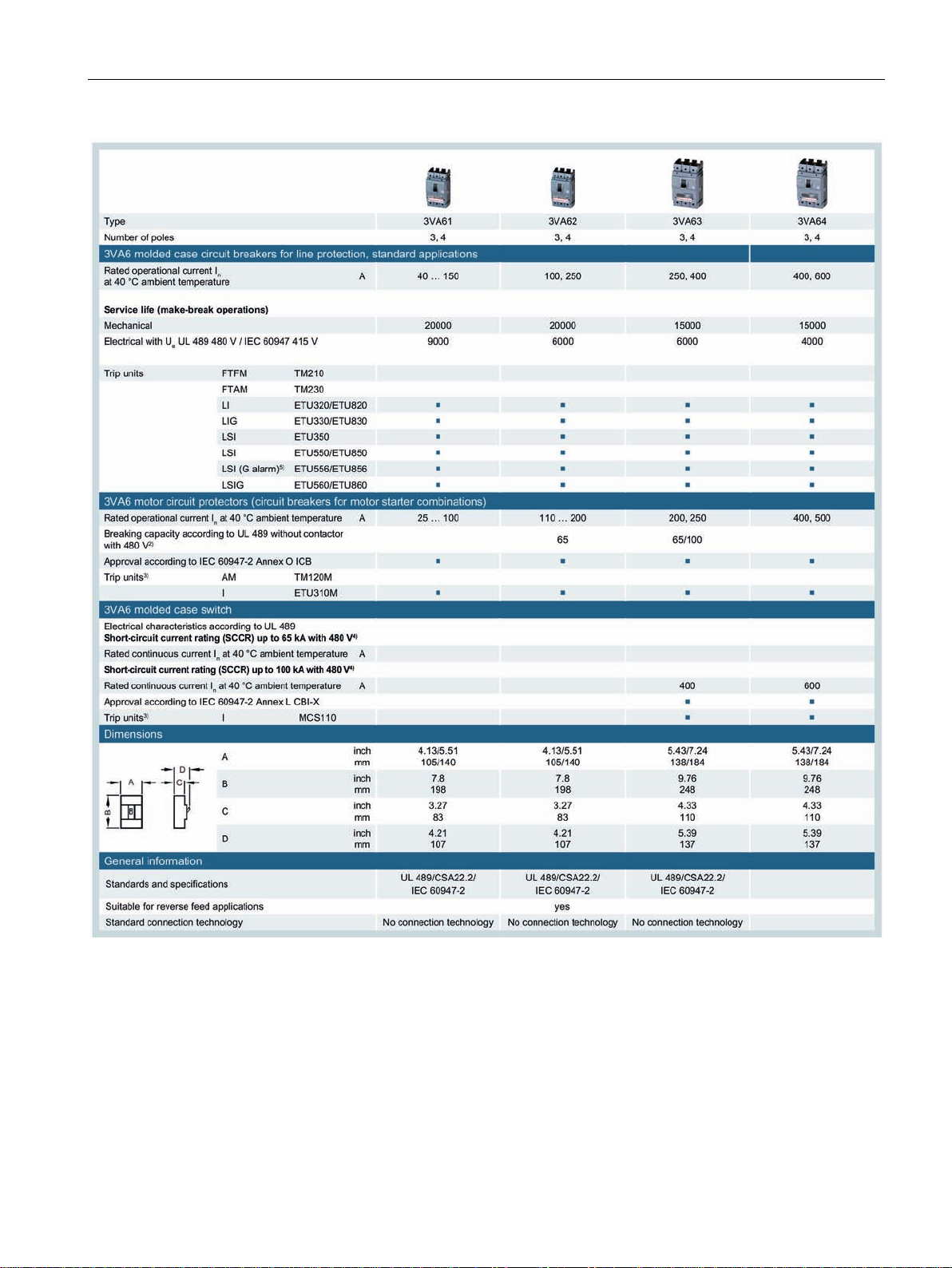
The 3VA6 molded case circuit breakers are available in the following versions:
● 3- and 4-pole version
The circuit breakers are suitable for rated operational currents ranging from 15 A to 600 A
and rated voltages up to 600 V AC, depending on the range and frame size.
3VA molded case circuit breakers with UL and IEC certification
16 Manual, 01/2019, L1V30435333-01

Description
3VA5 molded case circuit breakers
Features
Compact dimensions
Thermal-magnetic trip units
2.1 Overview - applications and portfolio
The new 3VA5 molded case circuit breakers reliably perform all the tasks required for line
protection.
The key features of the 3VA5 range are:
● Compact design
● Number of poles available (dependent on size):
– 1- and 3-pole versions in size 125 A
– (2)3-pole
1)
2-pole molded case circuit breaker in 3-pole frame
● Breaking capacity (dependent on size):
– 1-pole versions:
Breaking capacity of 25 kA to 50 kA at 277 V AC
– 3-pole versions:
Breaking capacity of 25 kA to 65 kA or 100 kA (3VA52) with 480 V AC
Breaking capacity of 50 kA to 100 kA with 500 V DC
1)
and 3-pole version in size 250 A
● Fixed mounting
● Thermal-magnetic trip units
● AC/DC applications
● Modular and easy-to-fit internal accessories with diverse functions
● Uniform accessories platform across all 3VA UL molded case circuit breakers
Due to its small dimensions, the 3VA UL molded case circuit breaker 125 A (3VA51) is
ideally suited to the protection of cables and systems wherever space is limited.
In addition, the 3VA51 molded case circuit breaker is suitable for mounting on 35 mm
DIN rails.
The 3VA5 molded case circuit breakers have a thermal-magnetic trip unit with overload and
short-circuit protection. This has been developed for implementing economical, cost-efficient
installations up to 250 A. It is suitable for use in three-phase networks, AC networks, and
400 Hz applications and with DC currents.
3VA molded case circuit breakers with UL and IEC certification
Manual, 01/2019, L1V30435333-01
17

Description
3VA6 molded case circuit breakers
Features
Compact dimensions with expanded functionality
2.1 Overview - applications and portfolio
The new 3VA6 molded case circuit breakers reliably perform all the tasks required for line
protection.
This range is designed for applications with more exacting requirements:
● Increased breaking capacity
● Compact dimensions
● Integrated metering function
● Connection to a fieldbus communication system
The key features of the 3VA6 range are:
● Compact dimensions
● 3 and 4-pole versions
● Four breaking capacity classes with breaking capacities of
– 35 kA to 150 kA with 480 V AC
– 18 kA to 50 kA with 600 V AC
● Fixed-mounting, plug-in technology, draw-out technology
● Electronic trip units (ETU)
● Retrofittable communication for ETU 5-series and 8-series
● Depending on the ETU: Integrated metering function for voltages, currents, powers, etc.
● AC applications
● No derating up to +50 °C
● Modular and easy-to-fit internal accessories with diverse functions
● Uniform accessories platform across all 3VA UL molded case circuit breakers
● Electronic Trip Units (ETU) with different setting values
Besides the expanded functionality, the 3VA6 molded case circuit breaker is also
characterized by its compact dimensions for fixed mounting. In addition, plug-in and draw-out
sockets are available for 3VA6 molded case circuit breakers. Standard switches can be
retrofitted for these mounting methods with little effort.
Moreover, the different breaking capacity classes available and the many possibilities
afforded by the various electronic trip units also provide the flexibility needed for planning.
3VA molded case circuit breakers with UL and IEC certification
18 Manual, 01/2019, L1V30435333-01

Description
Electronic trip unit (ETU)
Energy management and communication
2.1 Overview - applications and portfolio
The current sensor of the 3VA6 molded case circuit breaker comprises an iron-cored
transformer for the internal power supply and a Rogowski coil for precise sensing and
measurement of the current values. Each of these transformers was specifically optimized
for its task. Thanks to the high accuracy of current measurement achieved by the Rogowski
coil, the 3VA6 molded case circuit breaker is suitable for power and energy measurement. In
addition, finer adjustment of ground fault current monitoring is possible.
The electronic trip units (ETUs) provide the following protection functions:
● Overload protection L ("L" = Long-time delay)
Adjustable in steps from 40% to 100% of the rated operational current of the molded case
circuit breaker.
● Short-time delayed short-circuit protection S ("S" = Short-time delay) for time-selective
response in case of a short circuit
● Instantaneous short-circuit protection I ("I" = instantaneous):
● Protection of the neutral conductor against overload and short-circuit ("N" = neutral)
● Protection against residual currents to ground ("G" = Ground fault).
Two possibilities are available for protection against residual currents to ground:
● Tripping of the breaker when a ground fault is present and thus disconnection of the
system
● Alarm-only indication, via LED, that a ground fault is present. The signal is also available
through communication and a digital output, when applied with the appropriate
accessories.
The breaker is not tripped here, the system remains connected although the ground fault
still exists.
3VA6 molded case circuit breakers with corresponding ETUs are available for both
applications.
The Electronic Trip Units (ETUs) provide the following energy management and
communication functions:
● Metering functions for current, voltage, power and energy consumption
● Transfer of measured values and status information of the circuit breaker
● Remote parameter assignment of tripping thresholds and miscellaneous parameters
● Flexible use of digital inputs and outputs of the optionally available EFB300 external
function box
● Commissioning/setting the plant topology and also individual breaker parameters with the
"powerconfig" software package
● Testing and archiving with the TD300 and TD500 test devices (with powerconfig)
3VA molded case circuit breakers with UL and IEC certification
Manual, 01/2019, L1V30435333-01
19

Description
100% rated versions of the 3VA UL molded case circuit breaker
2.1 Overview - applications and portfolio
The US National Electrical Code, NEC recognizes two categories of overcurrent protective
devices (OCPD) and has different required load calculations for their application. The two
categories are standard OCPDs and OCPDs listed for operation at 100% of their rating
(commonly referred to as "100 % rated").
For standard OCPDs, the rating selected must be no less than the sum of 100% of the noncontinuous loads and 125% of the continuous loads (3 hours or more). For OCPDs listed for
operation at 100% of their rating, the calculation for the minimum rating is based on the sum
of 100% of the non-continuous loads and 100% of the continuous loads.
For 100% rated circuit breakers, there are additional UL489 requirements for the wire
connectors/lugs, conductor sizes and types, and minimum enclosure sizing.
3VA molded case circuit breakers with UL and IEC certification
20 Manual, 01/2019, L1V30435333-01
Description
2.1.4
Detailed information about applications and possible uses
2.1 Overview - applications and portfolio
3VA molded case circuit breakers with UL and IEC certification
Manual, 01/2019, L1V30435333-01
21
Description
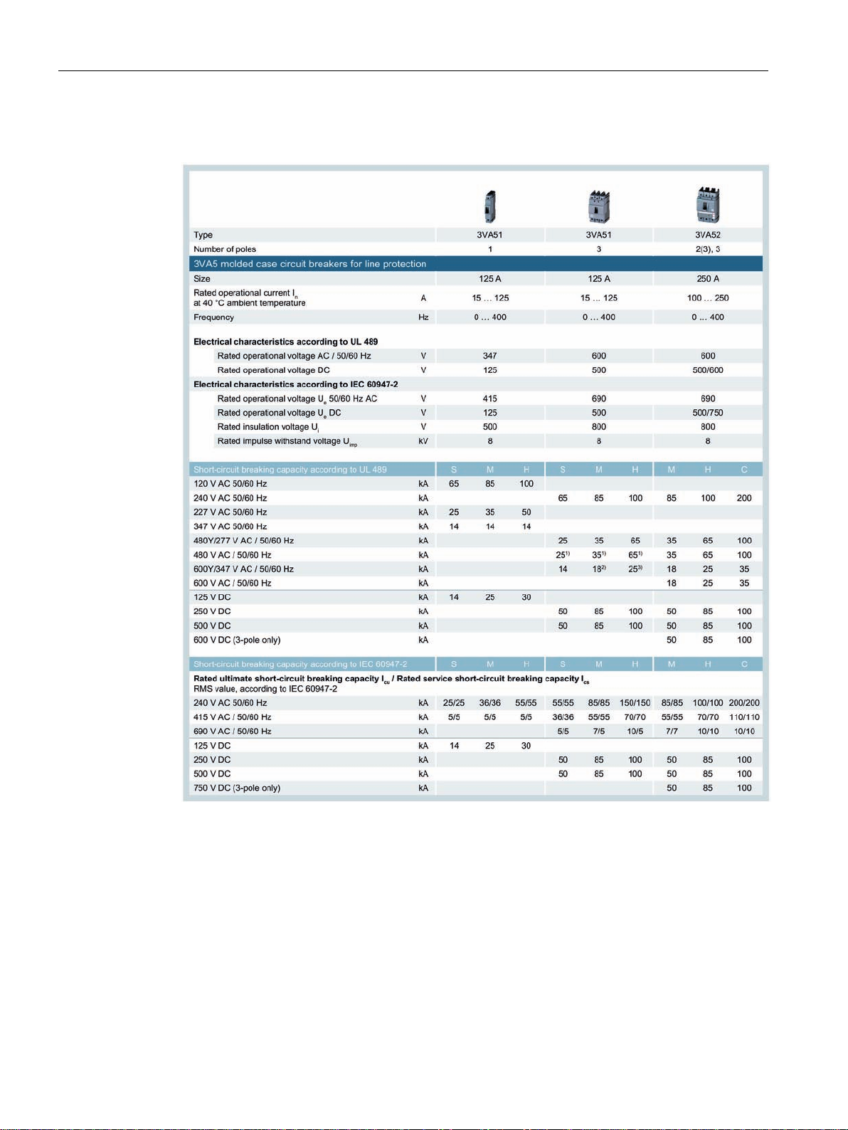
2.1.5
Technical specifications
2.1 Overview - applications and portfolio
1)
Applies to In 15 A to 90 A
2)
In 100 A to 125 A 14 kA
3)
In 40 A to 90 A 18 kA; 100 A to 125 A 14 kA
3VA molded case circuit breakers with UL and IEC certification
22 Manual, 01/2019, L1V30435333-01
Description
2.1 Overview - applications and portfolio
3VA molded case circuit breakers with UL and IEC certification
Manual, 01/2019, L1V30435333-01
23
Description
2.1 Overview - applications and portfolio
1)
G alarm, no G protection (the G function sends an alarm message but does not trip the circuit
breaker)
2)
Breaking capacities in combination with contactors (SCCR ratings) may differ
3)
Integrated instantaneous short-circuit release for self-protection
4)
The short-circuit current rating (SCCR rating) is the maximum permissible short-circuit current
at the installation location of the MCS in combination with an appropriate additional overload
protection device.
3VA molded case circuit breakers with UL and IEC certification
24 Manual, 01/2019, L1V30435333-01
Description
2.1 Overview - applications and portfolio
1)
G alarm, no G protection (the G function sends an alarm message but does not trip the circuit breaker)
2)
Breaking capacities in combination with contactors (SCCR ratings) may differ
3)
Integrated instantaneous short-circuit release for self-protection
4)
The short-circuit current rating (SCCR rating) is the maximum permissible short-circuit current at the installation
location of the MCS in combination with an appropriate short-circuit protection device.
3VA molded case circuit breakers with UL and IEC certification
Manual, 01/2019, L1V30435333-01
25
Description
2.1.6
Molded case circuit breakers and accessories in the system
2.1 Overview - applications and portfolio
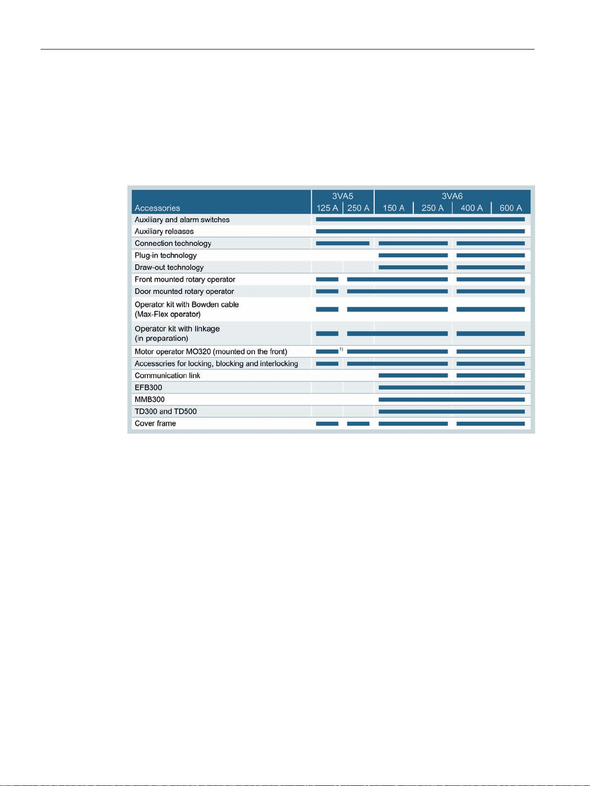
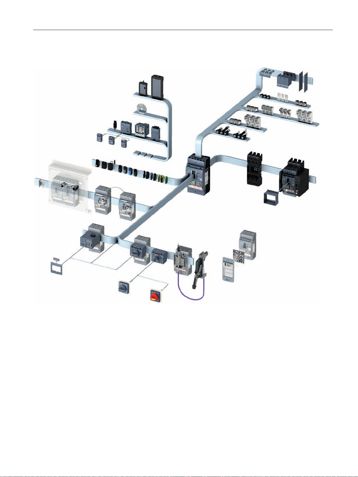
The new 3VA UL molded case circuit breakers come with a large portfolio of accessory
components that – depending on the type of accessory – can be flexibly installed internally or
externally regardless of the size of circuit breaker.
The table below indicates which accessories are compatible with particular molded case
circuit breakers, and which sizes of breakers are compatible with the same accessory:
1)
Only possible with fixed mounting and not when mounted on a DIN rail
3VA molded case circuit breakers with UL and IEC certification
26 Manual, 01/2019, L1V30435333-01
Description
Overview of accessories in the system
2.1 Overview - applications and portfolio
3VA molded case circuit breakers with UL and IEC certification
Manual, 01/2019, L1V30435333-01
27

Description
2.2
Ergonomic design
Integrated system
2.2.1
Installation variants for 3VA UL
2.2 Ergonomic design
This chapter provides an overview of the ergonomic design features of the new 3VA UL
molded case circuit breakers and explains what makes them so special.
The topics discussed in this chapter are listed below:
● Optional installation variants
● Color-coded indication of switching position in the draw-out unit
● Clear status indication
● Active illumination
● Ergonomic handle
● Color-coded control elements
● Broad range of accessories
● Connection options
The 3VA UL molded case circuit breakers set new standards, not only in terms of their
technical features and functional scope, but also in terms of their design.
The new 3VA UL range provides an integrated system with regard to operation, functionality
and installation. This principle is embodied in the basic units and in all internal and external
accessories.
The internal and external accessories of the 3VA UL molded case circuit breakers offer the
following benefits:
● Standardized methods of operation
● Standardized scope of functions
● Standardized installation procedures
● The same internal accessories for all circuit breaker sizes from 125 A to 600 A (auxiliary
switches, auxiliary releases)
To ensure full flexibility when planning a system, the molded case circuit breaker range can
be extended with additional components in such a way that operability is guaranteed in every
situation.
The following components can be installed to suit the installation location:
● Front mounted rotary operator
● Door mounted rotary operator
● Operator kit with Bowden cable (Max-Flex™ operator)
● Operator kit with rigid linkage (in preparation)
● Motor operator
3VA molded case circuit breakers with UL and IEC certification
28 Manual, 01/2019, L1V30435333-01
 Loading...