

Siemens SENTRON 3KC0 User Manual


___________________
___________________
___________________
___________________
___________________
___________________
___________________
___________________
___________________
___________________
___________________
___________________
___________________
___________________
SENTRON
Transfer switching equipment and
load transfer switches
3KC0 manual transfer switching
equipment
Manual
09/2018
L1V30368969105
Introduction
1
General information
2
Product information
3
Functions
4
Mounting
5
Connection
6
Operation
7
Accessories
8
Service and maintenance
9
Technical data
10
Dimension drawings
11
Appendix
A
ESD guidelines
B
List of abbreviations
C
-01
Siemens AG
Division Energy Management
Postfach 32 20
91050 ERLANGEN
GERMANY
Document order number: 3ZW1012-3KC03-0AC1
Ⓟ
Copyright © Siemens AG 2018.
All rights reserved
Legal information
Warning notice system
DANGER
indicates that death or severe personal injury will result if proper precautions are not taken.
WARNING
indicates that death or severe personal injury may result if proper precautions are not taken.
CAUTION
indicates that minor personal injury can result if proper precautions are not taken.
NOTICE
indicates that property damage can result if proper precautions are not taken.
Qualified Personnel
personnel qualified
Proper use of Siemens products
WARNING
Siemens products may only be used for the applications described in the catalog and in the relevant technical
ambient conditions must be complied with. The information in the relevant documentation must be observed.
Trademarks
Disclaimer of Liability
This manual contains notices you have to observe in order to ensure your personal safety, as well as to prevent
damage to property. The notices referring to your personal safety are highlighted in the manual by a safety alert
symbol, notices referring only to property damage have no safety alert symbol. These notices shown below are
graded according to the degree of danger.
If more than one degree of danger is present, the warning notice representing the highest degree of danger will
be used. A notice warning of injury to persons with a safety alert symbol may also include a warning relating to
property damage.
The product/system described in this documentation may be operated only by
task in accordance with the relevant documentation, in particular its warning notices and safety instructions.
Qualified personnel are those who, based on their training and experience, are capable of identifying risks and
avoiding potential hazards when working with these products/systems.
Note the following:
documentation. If products and components from other manufacturers are used, these must be recommended
or approved by Siemens. Proper transport, storage, installation, assembly, commissioning, operation and
maintenance are required to ensure that the products operate safely and without any problems. The permissible
All names identified by ® are registered trademarks of Siemens AG. The remaining trademarks in this publication
may be trademarks whose use by third parties for their own purposes could violate the rights of the owner.
We have reviewed the contents of this publication to ensure consistency with the hardware and software
described. Since variance cannot be precluded entirely, we cannot guarantee full consistency. However, the
information in this publication is reviewed regularly and any necessary corrections are included in subsequent
editions.
for the specific
01/2019 Subject to change

Table of contents
1 Introduction ................................................................................................................................................ 7
2 General information ................................................................................................................................... 9
3 Product information .................................................................................................................................. 11
4 Functions ................................................................................................................................................. 19
5 Mounting .................................................................................................................................................. 21
6 Connection .............................................................................................................................................. 33
1.1 Purpose of this manual ............................................................................................................. 7
1.2 Target groups and required basic knowledge .......................................................................... 7
1.3 Used symbols ........................................................................................................................... 8
2.1 Standards .................................................................................................................................. 9
2.2 Certification ............................................................................................................................... 9
3.1 Product description ................................................................................................................. 11
3.1.1 Design ..................................................................................................................................... 11
3.1.2 Current ratings ........................................................................................................................ 12
3.2 Product family ......................................................................................................................... 14
3.2.1 Use .......................................................................................................................................... 14
3.2.2 Properties ................................................................................................................................ 14
3.2.3 Applications ............................................................................................................................. 15
3.2.4 Structure of the article numbers .............................................................................................. 16
4.1 Function .................................................................................................................................. 19
5.1 Clearances for mounting ......................................................................................................... 21
5.2 Mounting positions .................................................................................................................. 24
5.2.1 Mounting position for sizes 1 and 2 ........................................................................................ 24
5.2.2 Mounting position for sizes 3, 4 and 5 .................................................................................... 24
5.3 Mounting the 3KC0 transfer switching equipment .................................................................. 25
5.3.1 DIN rail mounting for sizes 1 and 2 ......................................................................................... 25
5.3.2 Removal from DIN rail for sizes 1 and 2 ................................................................................. 26
5.3.3 Floor mounting for sizes 1 and 2 ............................................................................................ 27
5.3.4 Floor mounting for sizes 3, 4 and 5 ........................................................................................ 29
5.4 Affixing labels .......................................................................................................................... 30
6.1 Network types and applications .............................................................................................. 33
6.1.1 Transfer switching equipment ................................................................................................. 33
6.1.2 Load transfer switches ............................................................................................................ 35
6.2 Connecting to the circuit ......................................................................................................... 37
6.2.1 Load connection ...................................................................................................................... 37
6.2.2 Arrangement of the power supply systems ............................................................................ 37
6.2.3 Connecting the terminals for sizes 1 and 2 ............................................................................ 38
3KC0 manual transfer switching equipment
Manual, 09/2018, L1V30368969105-01
3

Table of contents
7 Operation ................................................................................................................................................. 51
8 Accessories ............................................................................................................................................. 55
6.2.4 Connecting transfer switching equipment sizes 1 and 2 ....................................................... 39
6.2.4.1 Connecting a bridging bar to sizes 1 and 2 ........................................................................... 39
6.2.4.2 Connecting transfer switching equipment sizes 1 and 2 to the circuit ................................... 41
6.2.5 Connecting the terminals for sizes 3, 4 and 5 ........................................................................ 44
6.2.6 Connecting transfer switching equipment sizes 3, 4 and 5 ................................................... 44
6.2.6.1 Connecting a bridging bar to sizes 3, 4 and 5 ....................................................................... 44
6.2.6.2 Connecting transfer switching equipment sizes 3, 4 and 5 to the circuit ............................... 48
7.1 Operating transfer switching equipment sizes 1 and 2 .......................................................... 51
7.2 Operating transfer switching equipment sizes 3, 4 and 5 ...................................................... 53
8.1 Component overview for sizes 1 and 2 .................................................................................. 56
8.2 Component overview for sizes 3, 4 and 5 .............................................................................. 57
8.3 Assembly kit for floor mounting for sizes 1 and 2 .................................................................. 58
8.4 Bridging bars .......................................................................................................................... 58
8.5 Additional poles for sizes 1 and 2 .......................................................................................... 61
8.5.1 Mounting additional poles for sizes 1 and 2 ........................................................................... 62
8.6 Auxiliary switches and auxiliary switch modules .................................................................... 64
8.6.1 Mounting auxiliary switches on sizes 1 and 2 ........................................................................ 67
8.6.2 Removing auxiliary switches from sizes 1 and 2 ................................................................... 68
8.6.3 Mounting auxiliary switches on sizes 3, 4 and 5 .................................................................... 68
8.6.4 Removing auxiliary switches from sizes 3, 4 and 5 ............................................................... 71
8.7 Door-coupling rotary operating mechanism of the 8UD1 series ............................................ 72
8.7.1 Component overview ............................................................................................................. 73
8.7.2 Types of delivery and versions .............................................................................................. 74
8.7.3 Mounting the door-coupling rotary operating mechanism ..................................................... 74
8.7.3.1 Use the hole drilling template for the cabinet door ................................................................ 74
8.7.3.2 Mounting the handle on the cabinet door .............................................................................. 76
8.7.3.3 Calculating shaft length and cutting shaft to size ................................................................... 77
8.7.3.4 Attaching the door-coupling driver to the shaft ...................................................................... 79
8.7.4 Function and operation .......................................................................................................... 83
8.7.4.1 Door padlocking ..................................................................................................................... 83
8.7.4.2 Tolerance compensation ........................................................................................................ 87
8.7.4.3 Padlocking .............................................................................................................................. 88
8.7.4.4 Assigning the switch position between the 8UD1 handle and 3KC0 ..................................... 90
8.7.5 Accessories for the 8UD1 series ............................................................................................
92
8.7.5.1 Handles .................................................................................................................................. 92
8.7.5.2 Coupling drivers ..................................................................................................................... 93
8.7.5.3 Extension shafts ..................................................................................................................... 94
8.7.5.4 Shaft coupling ........................................................................................................................ 95
8.7.5.5 Shaft jack for 3KC0 sizes 1 and 2 .......................................................................................... 96
8.7.5.6 Inscription label ...................................................................................................................... 97
8.8 Direct operating mechanism .................................................................................................. 98
8.8.1 Direct operating mechanism for sizes 1 and 2 ....................................................................... 98
8.8.1.1 Mounting the direct operating mechanism on sizes 1 and 2 ................................................. 99
8.8.1.2 Removing the direct operating mechanism from sizes 1 and 2 ........................................... 100
3KC0 manual transfer switching equipment
4 Manual, 09/2018, L1V30368969105-01

Table of contents
9 Service and maintenance ...................................................................................................................... 115
10 Technical data ....................................................................................................................................... 117
11 Dimension drawings .............................................................................................................................. 127
A Appendix ................................................................................................................................................ 131
B ESD guidelines ...................................................................................................................................... 135
C List of abbreviations ............................................................................................................................... 137
Index ...................................................................................................................................................... 139
8.8.2 Direct operating mechanism for sizes 3, 4 and 5 ................................................................. 100
8.8.2.1 Mounting the direct operating mechanism on sizes 3, 4 and 5 ............................................ 101
8.8.2.2 Removing the direct operating mechanism from sizes 3, 4 and 5 ........................................ 103
8.8.3 Padlocking mode for direct operating mechanism ................................................................ 103
8.8.3.1 Padlocking mode of direct operating mechanism for sizes 1 and 2 ..................................... 104
8.8.3.2 Padlocking mode of direct operating mechanism for size 3 ................................................. 104
8.8.3.3 Padlocking mode of direct operating mechanism for sizes 4 and 5 ..................................... 105
8.9 Phase barriers ....................................................................................................................... 105
8.9.1 Mounting phase barriers ....................................................................................................... 106
8.10 Terminal cover ...................................................................................................................... 108
8.10.1 Installing the terminal covers ................................................................................................ 109
8.10.2 Side panel covers for terminal covers ................................................................................... 111
8.11 Spare parts ........................................................................................................................... 113
10.1 Technical specifications of 3KC0 from 16 to 160 A .............................................................. 117
10.2 Technical specifications of 3KC0 from 200 to 500 A ............................................................ 120
10.3 Technical specifications of 3KC0 from 630 to 1600 A .......................................................... 123
11.1 Dimension drawings.............................................................................................................. 127
11.2 Dimension drawing of additional poles for sizes 1 and 2...................................................... 129
11.3 Dimension drawing of auxiliary switch for sizes 1 and 2 ...................................................... 129
A.1 Environmental conditions ...................................................................................................... 131
A.2 Operating conditions ............................................................................................................. 131
A.2.1 Temperature ......................................................................................................................... 131
A.2.2 Humidity ................................................................................................................................ 131
A.2.3 Altitude conditions ................................................................................................................. 132
A.3 Storage conditions ................................................................................................................ 132
A.3.1 Temperature ......................................................................................................................... 132
A.3.2 Storage conditions ................................................................................................................ 132
A.3.3 Storage position .................................................................................................................... 132
A.3.4 Dimensions and weight of the transfer switching equipment ............................................... 133
B.1 Introduction to ESD ............................................................................................................... 135
B.2 Electrostatic sensitive devices (ESD) ................................................................................... 135
C.1 List of abbreviations .............................................................................................................. 137
3KC0 manual transfer switching equipment
Manual, 09/2018, L1V30368969105-01
5


1
1.1
Purpose of this manual
1.2
Target groups and required basic knowledge
Scale
Technical Support
This manual describes the functions, commissioning and operation of the following transfer
switching equipment:
● 3KC0 manual transfer switching equipment (MTSE)
(MTSE = Manually Operated Transfer Switching Equipment)
This manual describes the following topics:
● Product specifications
● Mounting
● Connection
● Operation
● Commissioning
● Accessories
● Corrective maintenance and fault rectification
● Application examples
This manual is intended for:
● Users
● Electrically skilled persons
● Switchgear manufacturers
● Maintenance personnel
A general knowledge of low-voltage power distribution is required to understand this manual.
The diagrams are not shown in the original size (1:1 scale).
You can find further support on the Internet (https://www.siemens.com/lowvoltage/technical-
support).
3KC0 manual transfer switching equipment
Manual, 09/2018, L1V30368969105-01
7
Introduction
Applicable documents
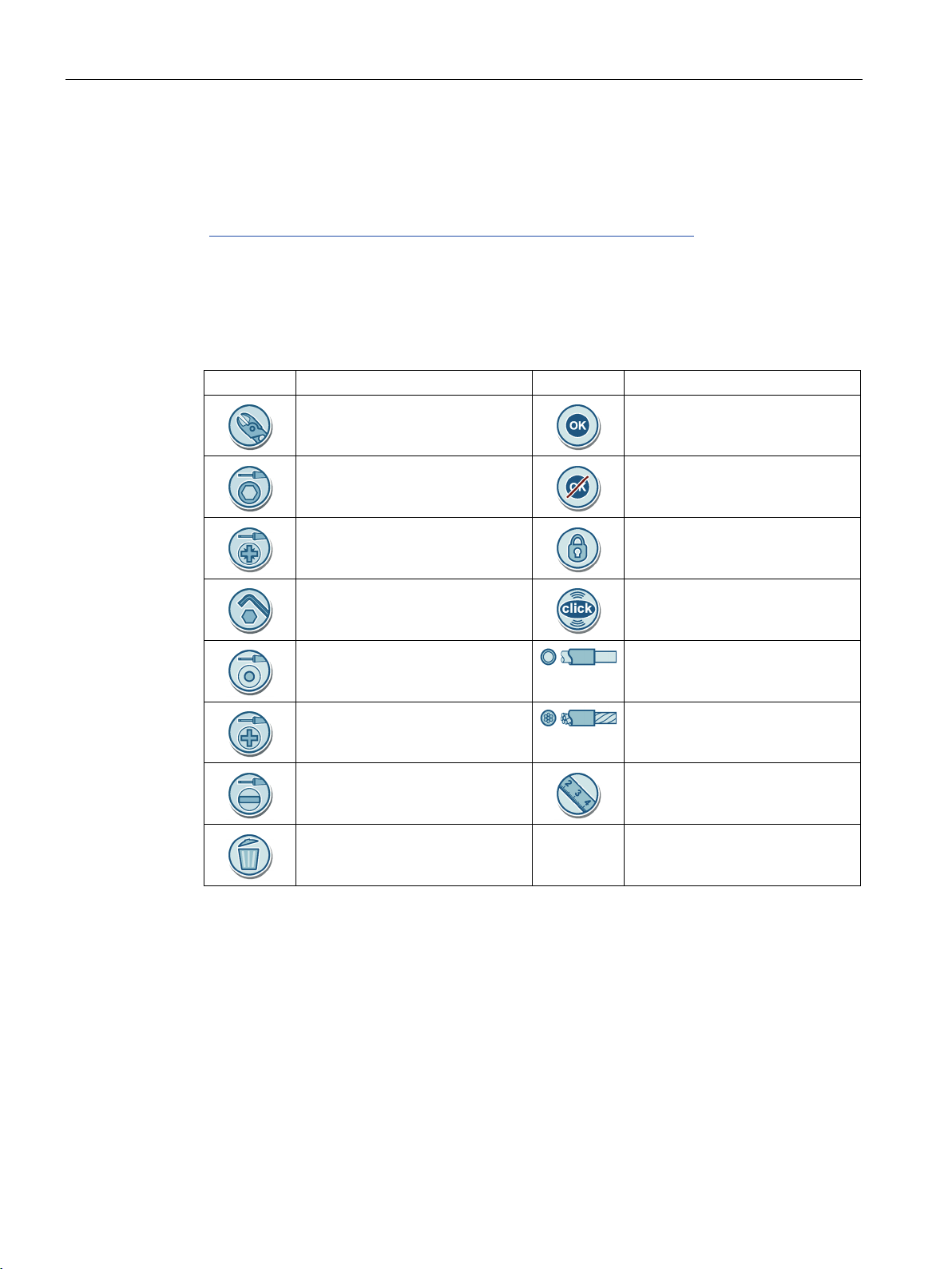
1.3
Used symbols
Symbol
Meaning
Symbol
Meaning
1.3 Used symbols
You can find more information on the Internet via the following link:
3KC0 manual transfer switching equipment
(https://support.industry.siemens.com/cs/products?mfn=ps&lc=en-US
)
Pliers
Hexagon socket wrench
Cross-tip screwdriver PZ
Wrench
Graver
Cross-tip screwdriver PH
Slotted screwdriver
Trash bin
OK
Not OK
Lock
Click to snap
Solid conductor
Stranded conductor
Measure
3KC0 manual transfer switching equipment
8 Manual, 09/2018, L1V30368969105-01

2
2.1
Standards
Standard
Designation
IEC 60269-1
Low-voltage fuses – Part 1: General requirements
technicians or electrically trained persons (fuses predominantly for industrial use)
– electromechanical control circuit devices
ing equipment
3-1: Conformity verification report for IEC 61010-1:2001 – General requirements
General requirements
2.2
Certification
IEC 60269-2 Low-voltage fuses - Part 2: Supplementary requirements for fuses for use by qualified electrical
IEC 60947-1 Low-voltage switchgear and controlgear – Part 1: General rules
IEC 60947-3 Low-voltage switchgear and controlgear – Part 3:
IEC 60947-5-1 Low-voltage switchgear and controlgear – Part 5-1: Control circuit devices and switching elements
The transfer switching equipment and its accessories comply with the following international
standards:
• Switches
• Disconnectors
• Switch-disconnectors
• Fuse-combination units
IEC 60947-6-1 Low-voltage switchgear and controlgear – Part 6-1: Multiple function equipment – Transfer switch-
IEC 61010-1 Safety requirements for electrical equipment for measurement, control, and laboratory use – Part
IEC 61326-1 Electrical equipment for measurement, control and laboratory use – EMC requirements – Part 1:
You can find the current certificates for this product in the Siemens Industrial Online Support
(https://support.industry.siemens.com/cs/ww/en/ps/cert
).
3KC0 manual transfer switching equipment
Manual, 09/2018, L1V30368969105-01
9

3
3.1
Product description
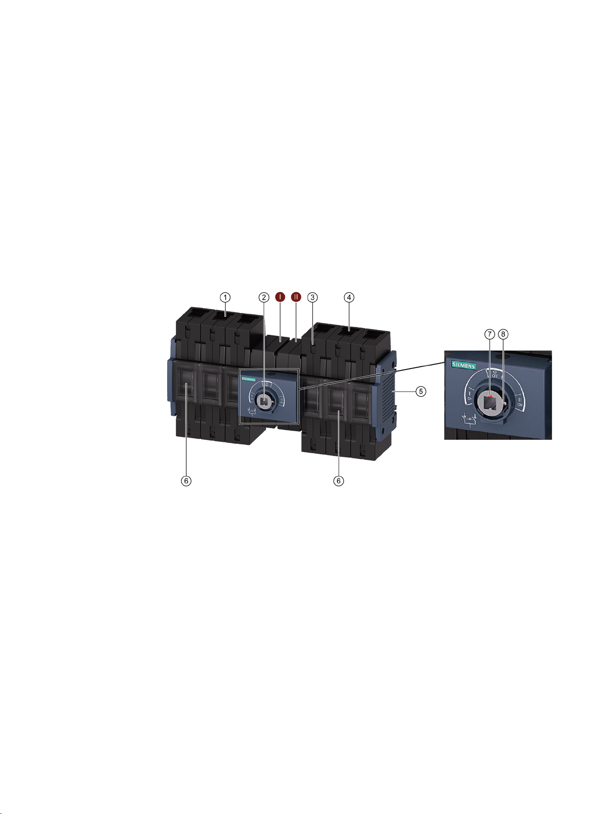
3.1.1
Design
Sizes 1 and 2
①
source I
⑥
②
mechanism
⑦
③
the cables in the box terminal
⑧
④
source II
⑤
Side panel cover
II
Switch II
Box terminals for connection of
Plug-in assembly for rotary operating
Safety locking mechanism for connecting
Box terminals for connection of
3KC0 manual transfer switching equipment
Manual, 09/2018, L1V30368969105-01
Switching unit
Switch position indicator
Fixing bolt
I Switch I
11
Product information
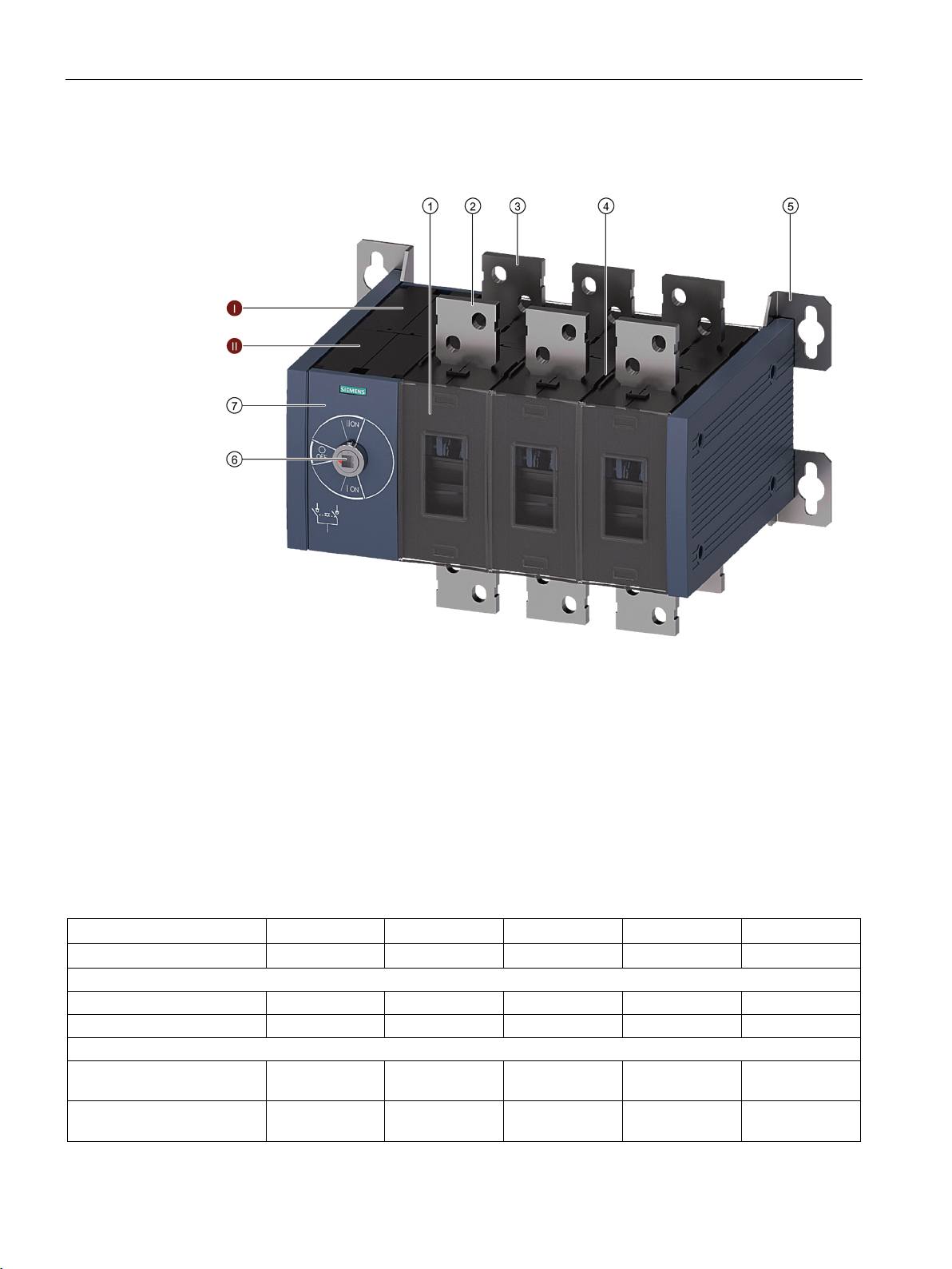
Sizes 3, 4 and 5
①
⑥
mechanism
②
Connecting terminals of source II
⑦
Cover
③
Connecting terminals of source I
I
Switch I
④
vers/phase barriers
⑤
Assembly for mounting
3.1.2
Current ratings
Size 1 2 3 4
5
Rated current (A)
16 … 63
80 … 160
200 … 400
500 … 800
1000 … 1600
Number of poles
3
✓ ✓ ✓ ✓ ✓ 4 ✓ ✓ ✓ ✓ ✓
Position of operating mechanism module
left
3.1 Product description
Switching unit
Plug-in assembly for terminal co-
Front operating mechanism,
center
Front operating mechanism,
Plug-in assembly for rotary operating
II Switch II
✓ ✓ – – –
– – ✓ ✓ ✓
3KC0 manual transfer switching equipment
12 Manual, 09/2018, L1V30368969105-01

Product information
Size 1 2 3 4
5
Rated current (A)
16 … 63
80 … 160
200 … 400
500 … 800
1000 … 1600
Type of mounting
ing)
DIN rail mounting
✓ ✓ – – –
Connections
Flat terminal
– – ✓ ✓ ✓
Box terminal
✓ ✓ – – –
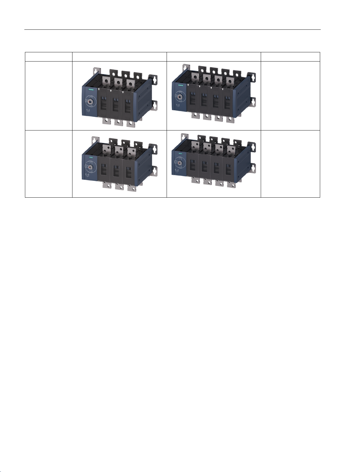
Sizes
3-pole
4-pole
Current rating (A)
Size 1
Size 2
Size 3
3.1 Product description
Floor mounting (wall mount-
* You can find more information in chapter Component overview for sizes 1 and 2 (Page 56).
The figures below show the sizes of the transfer switching equipment depending on the
current rating:
✓* ✓* ✓ ✓ ✓
• 16
• 32
• 63
3KC0 manual transfer switching equipment
Manual, 09/2018, L1V30368969105-01
• 80
• 100
• 125
• 160
• 200
• 250
• 315
• 400
13
Product information
3-pole
4-pole
Current rating (A)
Size 4
Size 5
3.2
Product family
3.2.1
Use
3.2.2
Properties
3.2 Product family
• 500
• 630
• 800
• 1000
• 1250
• 1600
The 3KC0 transfer switching equipment is used in power supply networks for load transfers
between the normal power source and an alternative power source with an interrupted
supply at current ratings up to 1600 A.
The 3KC0 transfer switching equipment can also be used as a load transfer switch for
switching between two loads.
● 3 and 4-pole transfer switching equipment for AC applications
● 5 sizes:
Sizes 1 and 2: 16 to 160 A (operating mechanism at center)
Sizes 3, 4 and 5 200 to 1600 A (operating mechanism on the left)
● Front operating mechanism
● Modular retrofittable additional poles (4th contact) for sizes 1 and 2
● Direct operating mechanism and door-coupling operating mechanism available as
accessories in gray or red/yellow.
3KC0 manual transfer switching equipment
14 Manual, 09/2018, L1V30368969105-01

Product information
3.2.3
Applications
Application areas
Non-residential/residential
Industry
Infrastructure
3.2 Product family
● Lockable handle
● Floor mounting or DIN rail mounting (up to 160 A)
The 3KC0 transfer switching equipment can be used in residential/non-residential, industrial
and infrastructure applications.
● Safety devices in high buildings
● Computing centers (e.g. in banks, insurance companies)
● Fire pumps, air conditioning systems, cold rooms
● Lighting systems in shopping malls
● Production lines in continuous operation
● Engine rooms
● Ancillary systems in crucial thermal power plants
● Pumps
● Cooling systems
● Fans
● Installations in ports and loading stations
● Airports
● Lighting
3KC0 manual transfer switching equipment
Manual, 09/2018, L1V30368969105-01
15
Product information
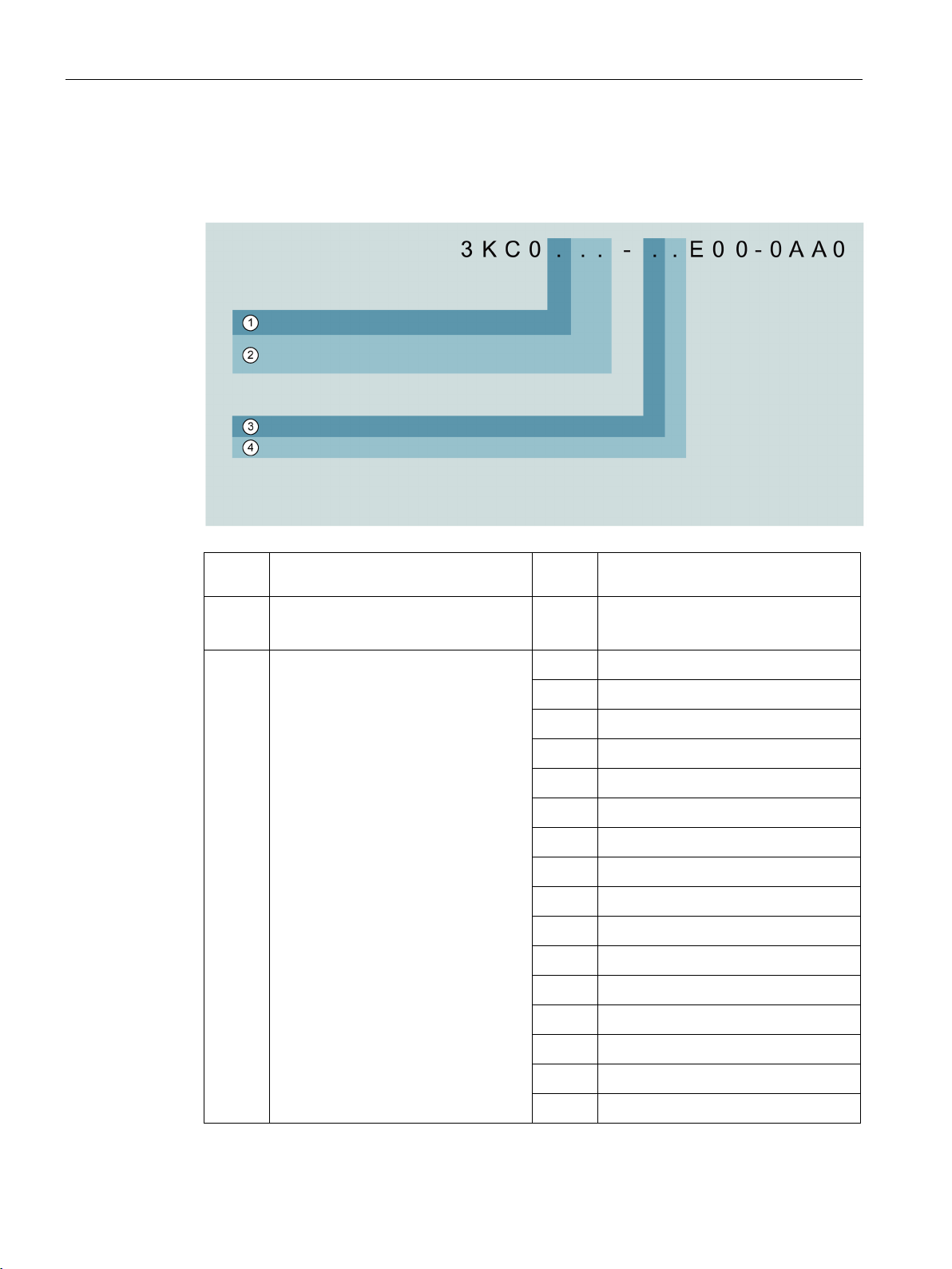
3.2.4
Structure of the article numbers
Article numbers for transfer switching equipment
Serial
No.
Description
Value
Explanation
②
3.2 Product family
①
Number of poles 3
Rated current 16
4
22
26
28
30
32
34
36
38
40
42
44
46
48
50
52
• 3-pole
• 4-pole
• 16 A
• 32 A
• 63 A
• 80 A
• 100 A
• 125 A
• 160 A
• 200 A
• 250 A
• 315 A
• 400 A
• 500 A
• 630 A
• 800 A
• 1000 A
• 1250 A
3KC0 manual transfer switching equipment
16 Manual, 09/2018, L1V30368969105-01
Product information
Serial
No.
Description
Value
Explanation
③
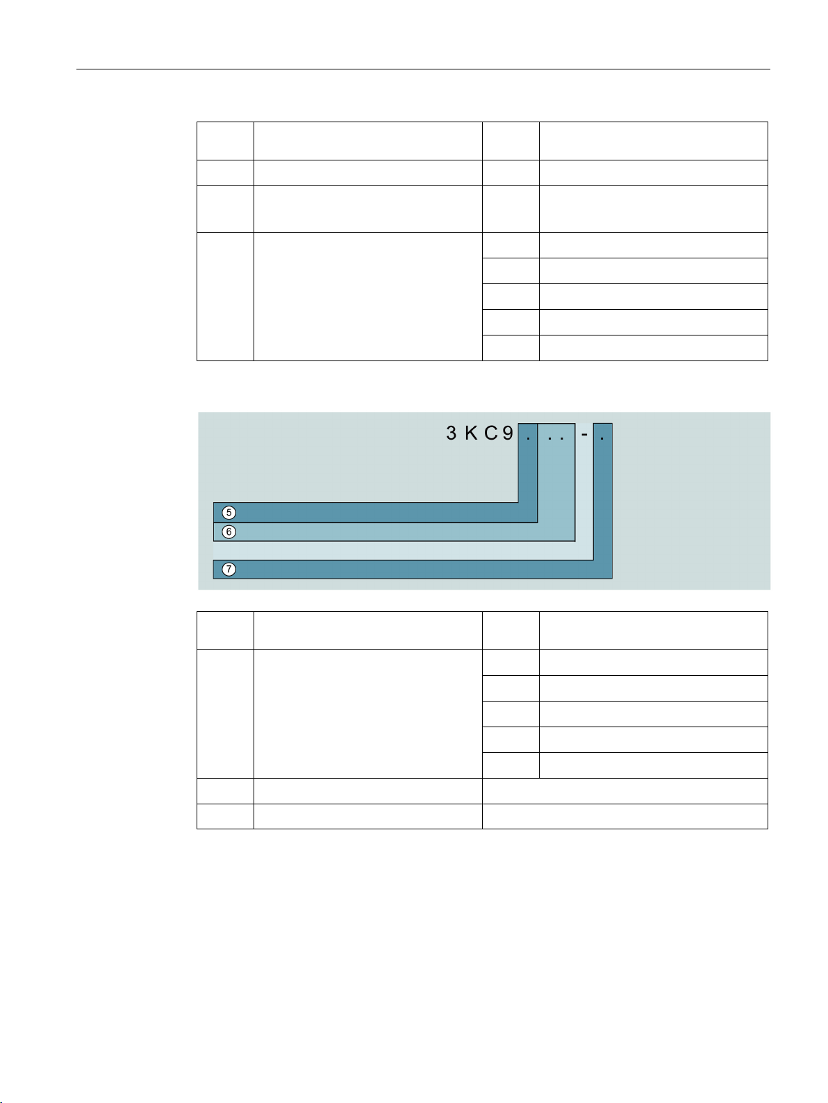
Article numbers for accessories
Serial
No.
Description
Value
Explanation
⑥
⑦
3.2 Product family
54
• 1600 A
Connection type 0
Size M
④
• Flat terminal
2
• Box terminal
• Size 1
N
• Size 2
P
• Size 3
Q
• Size 4
R
• Size 5
Suitable for transfer switching equip-
⑤
ment in size
Type of accessory
Accessory version
1
2
3
4
5
• Size 1
• Size 2
• Size 3
• Size 4
• Size 5
3KC0 manual transfer switching equipment
Manual, 09/2018, L1V30368969105-01
17


4
4.1
Function
The 3KC0 transfer switching equipment is used in power supply networks for load transfers
between the normal power source and an alternative power source with an interrupted
supply at current ratings up to 1600 A. Switchovers are performed manually.
The 3KC0 can be used for switching between two main sources, one main source and one
generator, or between two generators. It is possible to use the 3KC0 as transfer switching
equipment for switching between two sources in compliance with IEC 60947-6-1. It is also
possible to use the 3KC0 as a load transfer switch for switching between two loads in
compliance with IEC 60947-3.
3KC0 manual transfer switching equipment
Manual, 09/2018, L1V30368969105-01
19


5
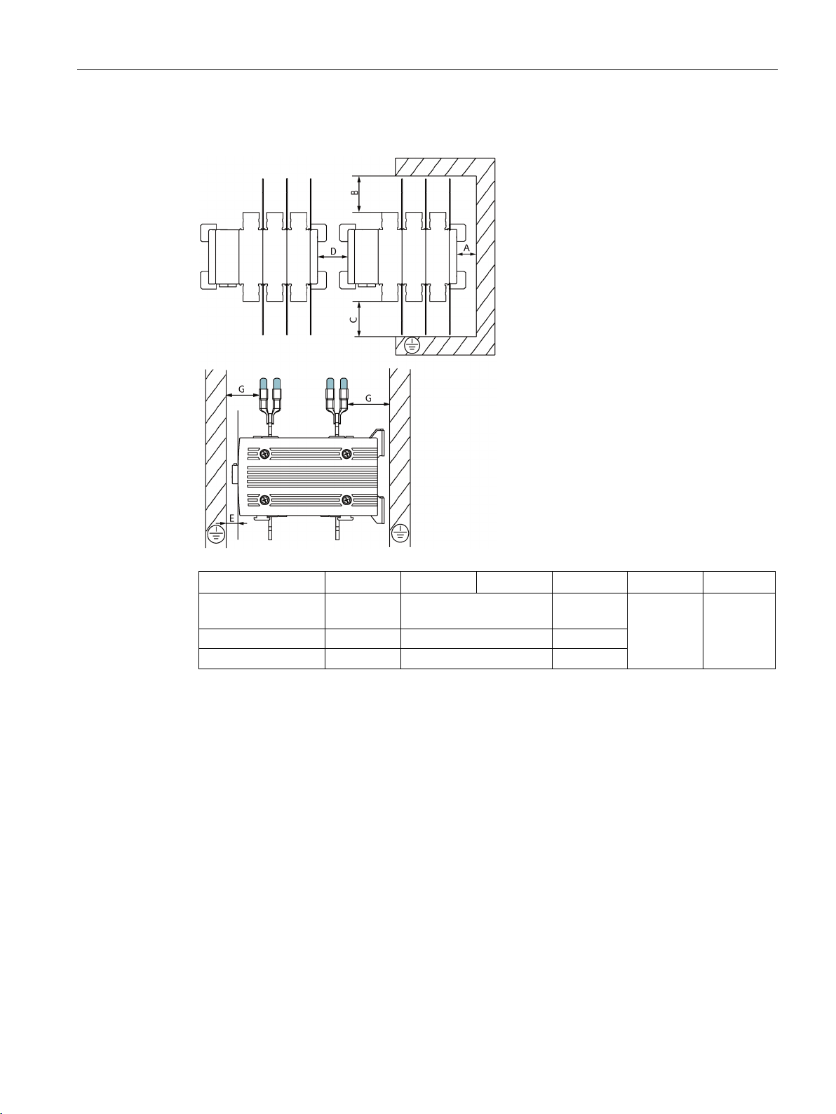
5.1
Clearances for mounting
Sizes 1 and 2
A (mm)
B (mm)
C (mm)
D (mm)
E (mm)
Size 1
0
10
0
Size 2
0
10
0
3KC0 manual transfer switching equipment
Manual, 09/2018, L1V30368969105-01
21
Mounting
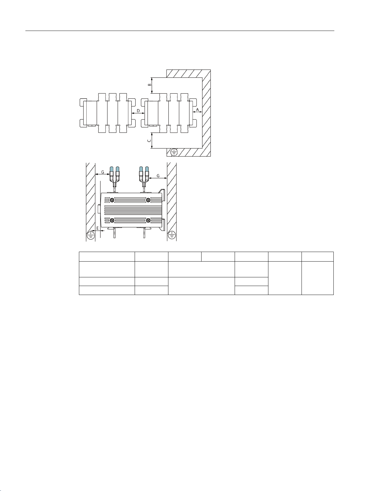
Sizes 3, 4 and 5 without phase barriers
A (mm)
B (mm)
C (mm)
D (mm)
E (mm)
G (mm)
42
3KC0.44 / 46 /48
30
47
5.1 Clearances for mounting
3KC0.36 / 38 / 40 /
3KC0.50 / 52 / 54 36.5 73
20 40 33 0 14
50
3KC0 manual transfer switching equipment
22 Manual, 09/2018, L1V30368969105-01
Mounting
Sizes 3, 4 and 5 with phase barriers
A (mm)
B (mm)
C (mm)
D (mm)
E (mm)
G (mm)
42
3KC0.44 / 46 /48
23.5
50
47
5.1 Clearances for mounting
3KC0.36 / 38 / 40 /
3KC0.50 / 52 / 54 36.5 70 73
16.5 44.5 33 0 14
3KC0 manual transfer switching equipment
Manual, 09/2018, L1V30368969105-01
23
Mounting
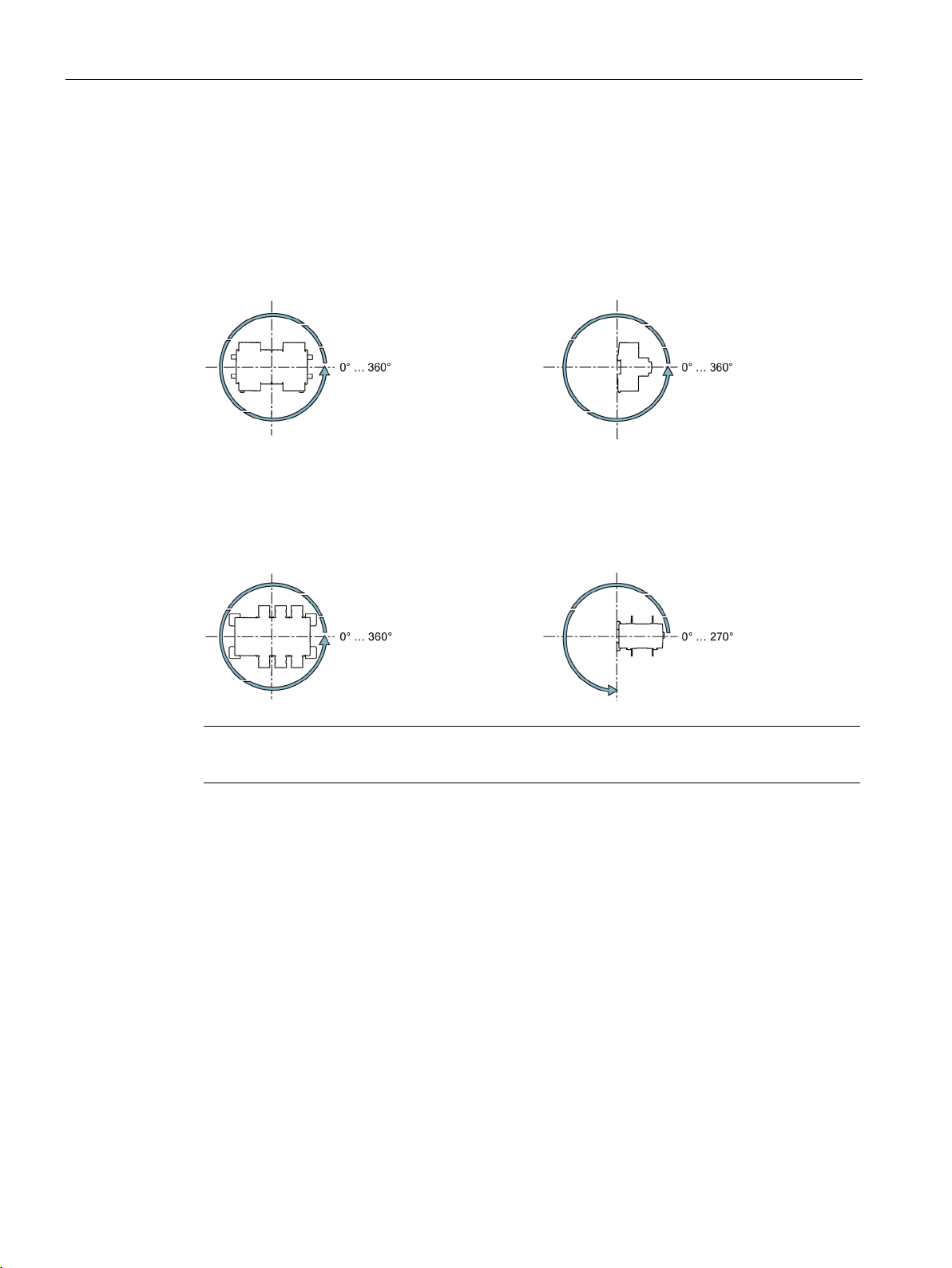
5.2
Mounting positions
5.2.1
Mounting position for sizes 1 and 2
5.2.2
Mounting position for sizes 3, 4 and 5
Note
Overhead mounting is
5.2 Mounting positions
not permitted for sizes 3, 4 and 5.
Some applications require the use of phase barriers. You can find more information in
chapter Phase barriers (Page 105).
3KC0 manual transfer switching equipment
24 Manual, 09/2018, L1V30368969105-01
Mounting
5.3
Mounting the 3KC0 transfer switching equipment
Note
If you need one of the following accessories, you must
the transfer switching equipment:
•
•
•
•
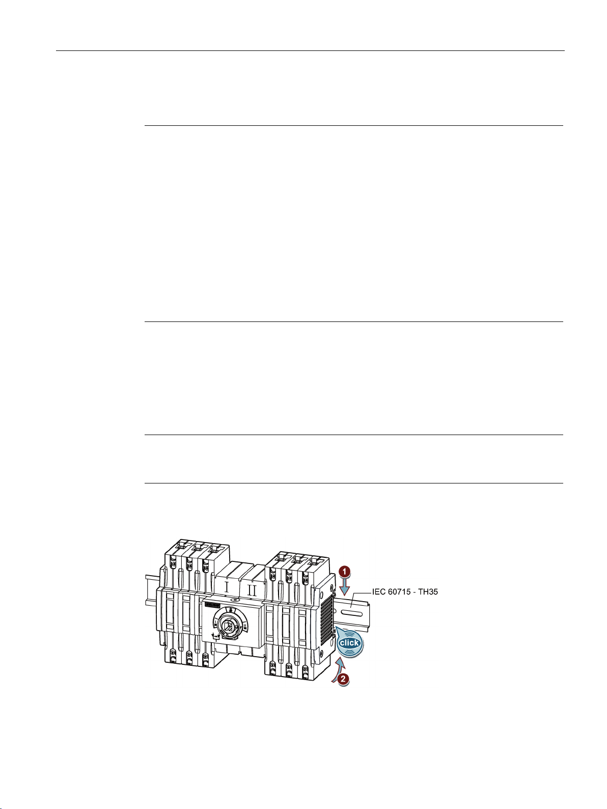
5.3.1
DIN rail mounting for sizes 1 and 2
Overview
Note
You are not permitted
mounting.
5.3 Mounting the 3KC0 transfer switching equipment
fit the accessory before you mount
Floor mounting for sizes 1 and 2
Assembly kit for floor mounting
You can find more information in chapter
Component overview for sizes 1 and 2
(Page 56).
Auxiliary switch module for sizes 1 and 2
You can find more information in chapter
Auxiliary switches and auxiliary switch modules
(Page 64).
Additional poles for sizes 1 and 2
You can find more information in chapter
Additional poles for sizes 1 and 2 (Page 61).
Direct operating mechanism
You can find more information in chapter
Direct operating mechanism (Page 98).
The figure below shows the procedure for mounting the 3KC0 transfer switching equipment
on a DIN rail (in compliance with DIN RAIL IEC 60715).
to install the assembly kit for floor mounting in the case of DIN rail
3KC0 manual transfer switching equipment
Manual, 09/2018, L1V30368969105-01
25
Mounting
Procedure
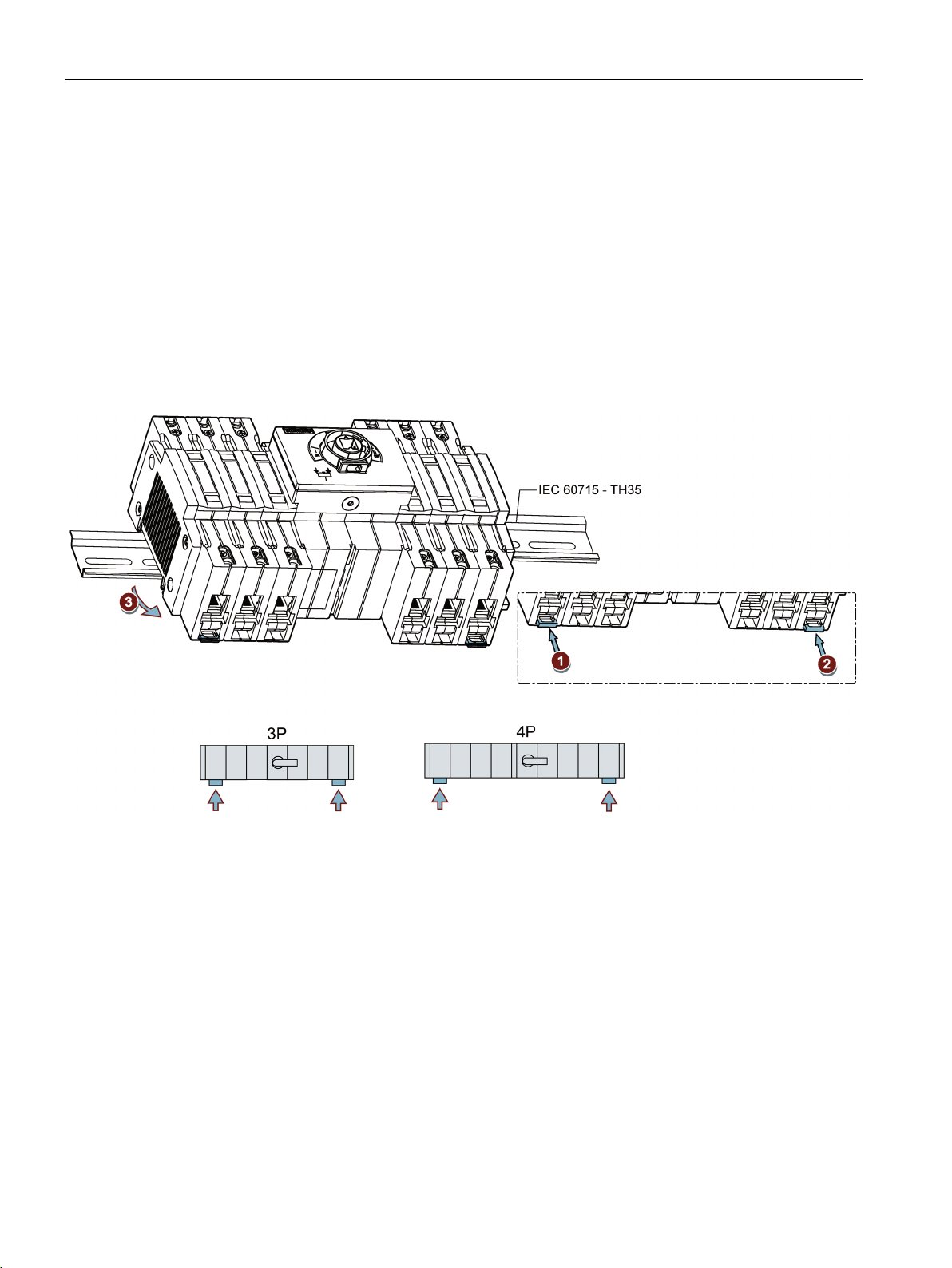
5.3.2
Removal from DIN rail for sizes 1 and 2
Overview
Procedure
5.3 Mounting the 3KC0 transfer switching equipment
1. Insert the transfer switching equipment with the plug-in assembly on the DIN rail from
above.
2. Push the transfer switching equipment back until the plug-in assembly audibly locks into
place on the underside.
1. Lever the first slide for DIN rail mounting out of the enclosure, e.g. using a slotted
screwdriver.
The slide locks into place audibly.
2. Lever the second slide for DIN rail mounting out of the enclosure, e.g. using a slotted
screwdriver.
The slide locks into place audibly.
3. Lift the transfer switching equipment off the DIN rail.
4. Push the first slide into the enclosure.
5. Push the second slide into the enclosure.
3KC0 manual transfer switching equipment
26 Manual, 09/2018, L1V30368969105-01
Mounting
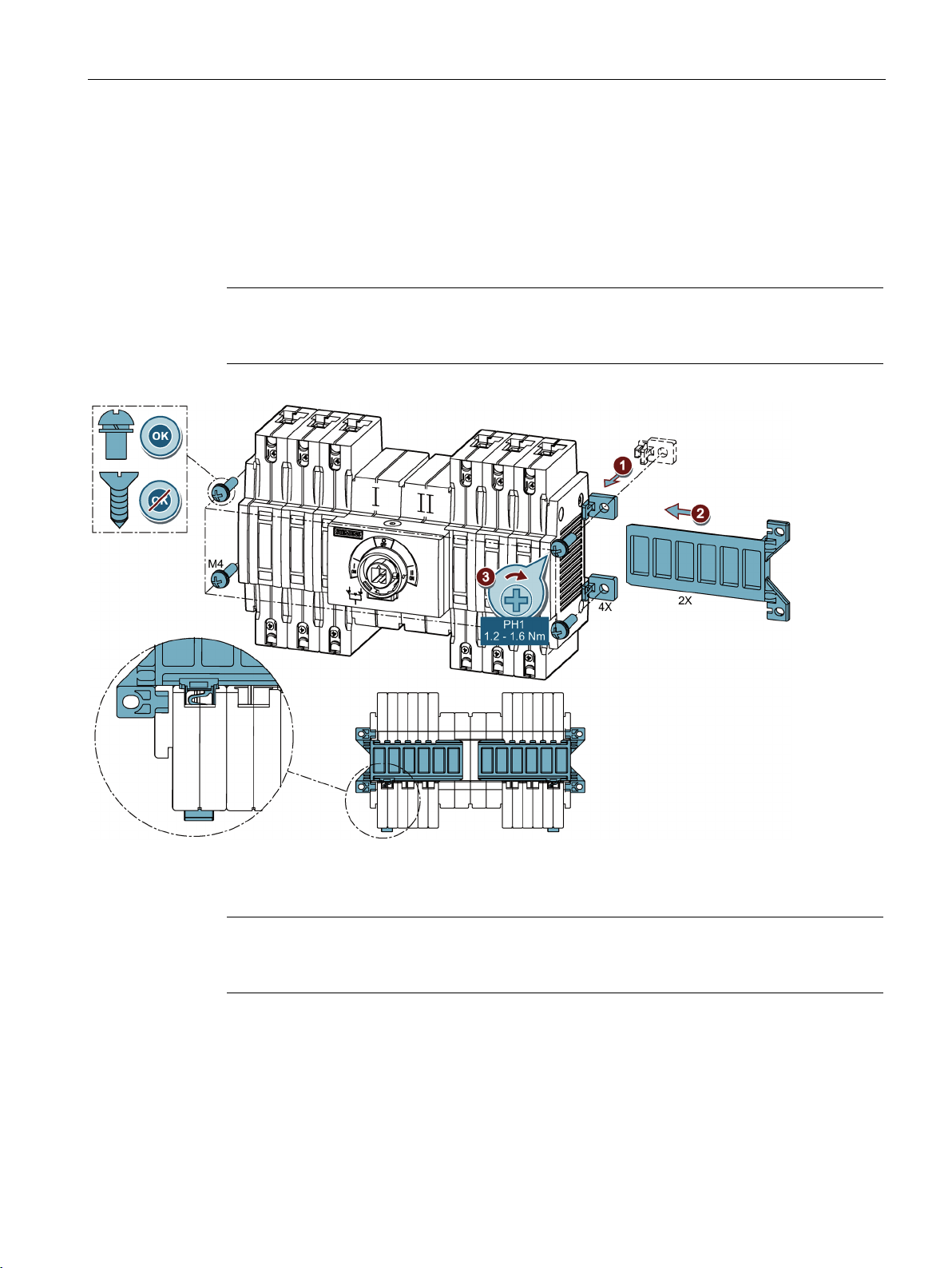
5.3.3
Floor mounting for sizes 1 and 2
Overview
Note
The assembly kit for floor mounting including the mounting bracket are not included in the
scope of supply.
Procedure
Note
Once you have inserted the mounting bracket into the recess of the side panel cover, it is not
possible to
5.3 Mounting the 3KC0 transfer switching equipment
A 3KC9120-1 assembly kit for floor mounting is needed for floor mounting. You can find
more information in chapter Component overview for sizes 1 and 2 (Page 56).
remove it again.
1. Push the four mounting brackets into the recesses on the side panel cover.
2. Push the two mounting plates on the underside on the left and right into the DIN rail guide
until they engage. Ensure that the openings for the bolts on the mounting brackets and on
the mounting plates are aligned with each other.
3. Mount the transfer switching equipment in the desired position using four bolts.
3KC0 manual transfer switching equipment
Manual, 09/2018, L1V30368969105-01
27
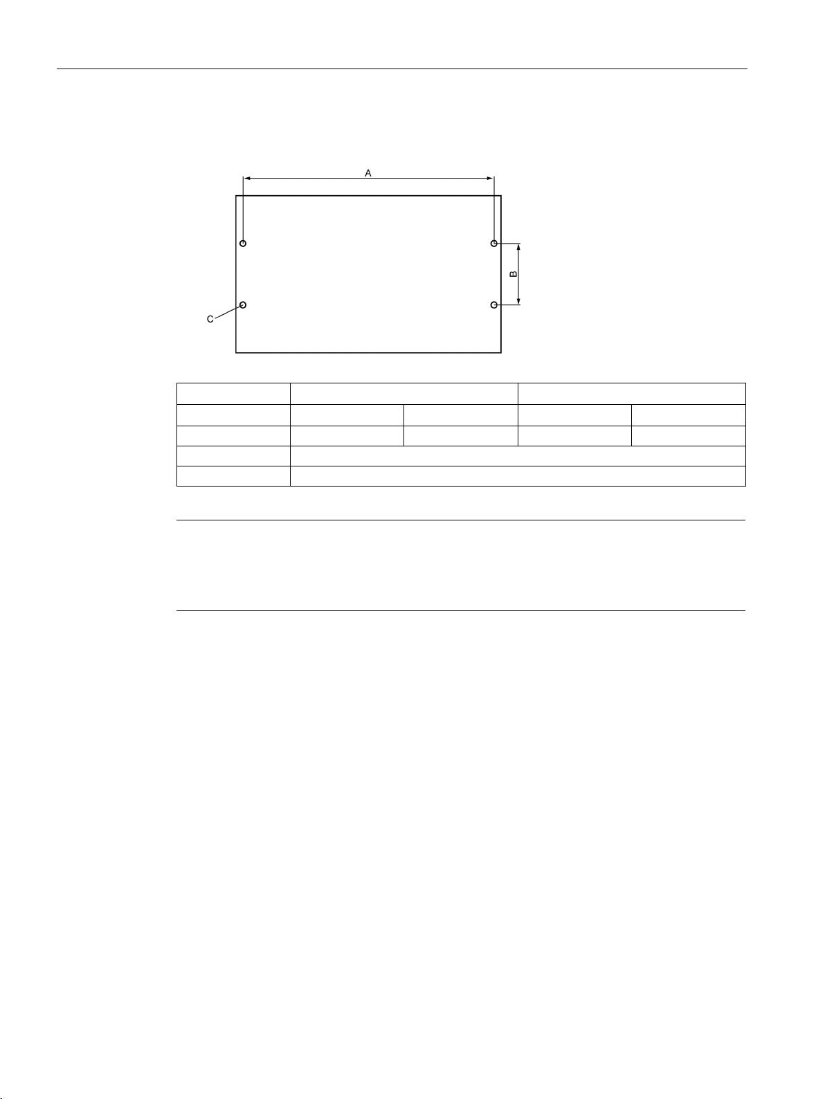
Mounting
Clearances for mounting
Size 1
Size 2
mm 3 4 3 4
A
191
227
245
299
B
46.5
C
4.5 (suitable for M4 bolts)
Note
The clearances change when auxiliary switch modules and additional poles are used. You
can find more information in chapter
See also chapter
5.3 Mounting the 3KC0 transfer switching equipment
Component overview for sizes 1 and 2 (Page 56).
Component overview for sizes 1 and 2 (Page 56).
3KC0 manual transfer switching equipment
28 Manual, 09/2018, L1V30368969105-01
 Loading...