

Page 1
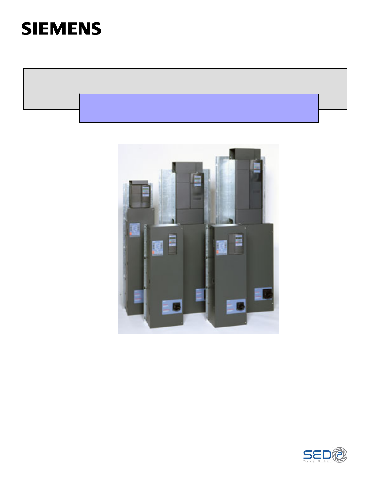
SED2 VFD Electronic Bypass Options
Operating Instructions
Item Number 125-3208, Rev. FA
Page 2

Page 3

SED2 VFD Electronic
Bypass Option
Operating Instructions
Page 4

Page 5

NOTICE
The information contained within this document is subject to change without notice and should not be
construed as a commitment by Siemens Building Technologies, Inc. Siemens Building Technologies, Inc.
assumes no responsibility for any errors that may appear in this document.
All software described in this document is furnished under a license and may be used or copie d only in
accordance with the terms of such license.
WARNING
The Siemens Building Technologies SED2 Variable Frequency Drives are shipped w ithout EMC line filters.
(The EMC filter is most commonly used in Europe.) Where local codes or customer/installation requirements
dictate, separately orderable Class A line filters are available. More stringent Class B line filters are also
available for most models. Installation of these filters satisfies the requirements for the EU's EMC directive.
SERVICE STATEMENT
Control devices are combined to make a system. Each control device is mechanical in nature and all
mechanical components must be regularly serviced to optimize their operation. All Siemens Building
Technologies, Inc. branch offices and authorized distributors offer Technical Support Programs that will
ensure your continuous, trouble-free system performance.
For further information, contact your nearest Siemens Building Technologies, Inc. representative.
CREDITS
Product or company names mentioned herein may be the trademarks of their respective owners.
Copyright © 2007 by Siemens Building Technologies, Inc.
TO THE READER
Your feedback is important to us. If you have comments about this manual, please submit them to
SBT_technical.editor@siemens.com
Country of Origin: US
Page 6

Page 7

Table of Contents
How to Use this Manual................................................................................................ 1
Manual Organization.................................................................................................. 1
Manual Notations....................................................................................................... 1
Where To Send Comments ....................................................................................... 2
Reference Documents ............................................................................................... 2
Safety Instructions........................................................................................................ 3
Electronic Bypass Option Overview........................................................................... 4
General Description ................................................................................................... 4
Controller Board......................................................................................................... 5
Contactors.................................................................................................................. 6
Table of Contents
Keypad Functions ...................................................................................................... 6
Installation Instructions ............................................................................................... 9
Environmental Conditions.......................................................................................... 9
Mechanical Installation .............................................................................................. 9
Inspection ................................................................................................................ 9
Dimensions and Weights ........................................................................................ 9
Mounting.................................................................................................................. 10
Electrical Installation .................................................................................................. 12
Startup Procedures....................................................................................................... 19
Safety Precautions..................................................................................................... 19
Installation Inspection ................................................................................................ 19
Power-On................................................................................................................... 19
Quick Commissioning ................................................................................................ 21
Additional Parameter Settings ................................................................................... 31
Flying Start .............................................................................................................. 31
Automatic Restart.................................................................................................... 33
Vdc Controller.......................................................................................................... 36
Pulse Frequency ..................................................................................................... 37
Motor Data Identification ......................................................................................... 38
Reset to Factory Defaults........................................................................................ 40
Required SED2 Parameter Settings............................................................................ 41
Siemens Building Technologies, Inc. i
Page 8

SED2 VFD Electronic Bypass Option Operating Instructions
Application Feature Setup ........................................................................................... 42
Overview .................................................................................................................... 42
Auto Bypass without Interlock.................................................................................... 42
Description .............................................................................................................. 42
Settings ................................................................................................................... 43
Example SED2 Settings.......................................................................................... 43
Interlock ..................................................................................................................... 44
Description .............................................................................................................. 44
Settings ................................................................................................................... 44
Wiring Example for Interlock ................................................................................... 46
Essential Services...................................................................................................... 46
Description .............................................................................................................. 46
Settings ................................................................................................................... 47
Wiring Example for Essential Services ................................................................... 47
Interlock and Auto Bypass on VFD Fault................................................................... 48
Description .............................................................................................................. 48
Settings ................................................................................................................... 48
Wiring Example for Interlock and Auto Bypass on VFD Fault ................................ 48
Technical Specifications.............................................................................................. 49
Troubleshooting............................................................................................................ 51
Power-on Initialization Failure (Unit Fault Condition) ............................................... 51
Override Jumper ........................................................................................................ 52
Fuses ......................................................................................................................... 52
ii Siemens Building Technologies, Inc.
Page 9
How to Use this Manual
Manual Organization
This manual contains the following sections:
• How to Use this Manual, describes the organization of this manual and the
symbols used throughout this manual.
• Safety Instructions, provides general guidelines for your safety and to
prevent equipment damage.
• Electronic Bypass Option Overview, describes the Electronic Bypass Option
Controller board, inputs, outputs, contactors, and keypad.
How to Use this Manual
• Installation Instructions, provides mounting information and details on
electrical connections.
• Startup Procedures, provides step-by-step procedures to start up the
Electronic Bypass Option.
• Required SED2 Parameter Settings, lists SED2 parameter settings
necessary for operation of the Electronic Bypass Option.
• Application Feature Setup, describes application features and provides the
necessary parameter settings.
• Technical Specifications, lists Electronic Bypass Option and SED2 VFD
specifications.
• Troubleshooting, provides guidelines for troubleshooting the Electronic
Bypass Option.
Manual Notations
Notation Symbol Meaning
WARNING:
Indicates that personal injury/loss of life may occur if you do
not perform a procedure as specified.
CAUTION:
NOTES:
Siemens Building Technologies, Inc. 1
(no symbol) Provides other important information or helpful hints.
Indicates that equipment damage, or loss of data may occur if
you do not perform a procedure as specified.
Page 10

SED2 VFD Electronic Bypass Option Operating Instructions
Where To Send Comments
Your feedback is important to us. If you have comments about this manual, please
submit them to technical.editor@sbt.siemens.com
Reference Documents
The following SED2 documentation is available from your local Siemens Building
Technologies, Inc. representative:
• SED2 VFD Startup Operation, and Maintenance Manual (125-3201),
provides operating instructions and procedures for the SED2.
• SED2 VFD Parameter Reference Guide (125-3214), provides descriptions of
SED2 parameters.
• SED2 VFD Submittal Sheet (154-042), provides a synopsis of the SED2
product line, accessories, and technical data.
.
• SED2 VFD Electronic Bypass Options Submittal Sheet (154-051), provides a
comprehensive overview of the SED2 Electronic Bypass option.
2 Siemens Building Technologies, Inc.
Page 11

Safety Instructions
The following guidelines are provided for your safety, to prevent damage, and to
extend the service life of the SED2 product and any connected equipment. Read this
information carefully. Specific Warnings, Cautions, and Notes are provided in the
relevant sections of this manual.
WARNING:
• The SED2 uses hazardous voltages and controls potentially dangerous
rotating mechanical parts. Non-compliance with warnings or failure to follow
the instructions contained in this manual can result in loss of life, severe
personal injury, or serious damage to property/equipment.
• Only authorized personnel should work on this equipment, and only after
becoming familiar with all local regulations and ordinances; safety notices;
and installation, operation, and maintenance procedures in this manual.
Successful and safe operation of this equipment depends upon its proper
handling, installation, operation, and maintenance.
Safety Instructions
• Before carrying out any installation and commissioning procedures, you
must read all safety instructions and warnings, including all warning labels
attached to the equipment. Make sure that the warning labels are kept in a
legible condition and ensure missing or damaged labels are replaced.
• Observe the regulations of Safety Code VBG 4.0 (in particular, “Permissible
Deviations when Working with Live Parts”) whenever measuring or testing is
performed on live equipment. Also, use suitable electronic tools.
• Only use this equipment for the purpose specified by the manufacturer.
Unauthorized modifications and the use of spare parts and accessories that
are not sold or recommended by the manufacturer of the equipment can
cause fires, electric shocks, and injuries.
• Prevent the general public from accessing or approaching this equipment.
NOTE: Keep these Operating Instructions near the equipment and available to all
users.
Siemens Building Technologies, Inc. 3
Page 12
SED2 VFD Electronic Bypass Option Operating Instructions
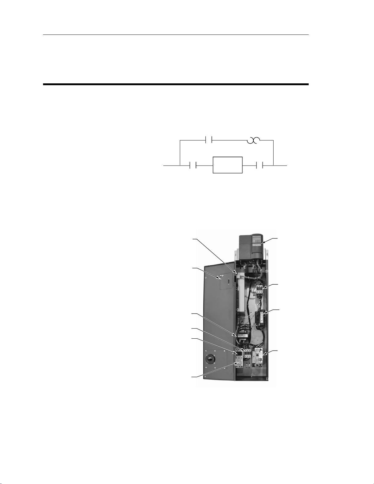
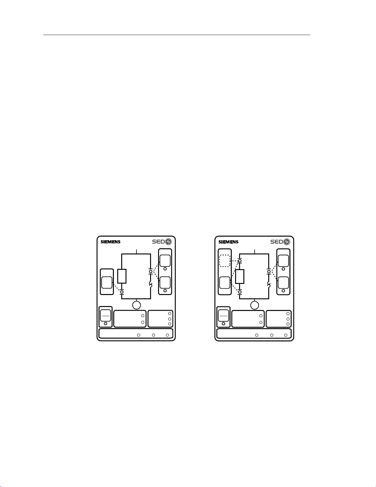
Electronic Bypass Option Overview
General Description
During normal operation in a typical
application, the input and output
contactors close and the SED2
operates the motor (Figure 1). The
bypass contactor provides the ability to
operate the motor on utility power and
eliminate the SED2 from the motor
control circuit. The SED2 Electronic
Bypass Option also allows you to select
features that enhance the control of the
contactors and the outputs that report
operation.
The SED2 Electronic Bypass
(E-Bypass) Option consists of a SED2
VFD, and a bypass enclosure with
electronic controls (Figure 2). The
electronic controls include:
• Controller board
• Keypad
• Step-down power transformer
• Contactors:
− Bypass
− Output
− Input (optional)
INPUT
CONTACTOR
VFD0093R1
Figure 1. Functional Block Diagram of
CONTROLLER
BOARD
KEYPAD
(DOOR
MOUNTED)
STEP-DOWN
POWER
TRANSFORMER
OUTPUT
CONTACTOR
BYPASS
CONTACTOR
BYPASS
CONTACTOR
OVERLOAD
RELAY
VFD
OUTPUT
CONTACTOR
Typical Electronic Bypass Option.
CONTACTOR
MOTOR
SED2 VFD
INPUT
REACTOR
(OPTIONAL)
• Overload (current) relay
• Reactor (optional)
• Disconnect switch (or optional
circuit breaker)
• Fuses (optional)
OVERLOAD
(CURRENT)
RELAY
VFD0094R1
Figure 2. Typical SED2 E-Bypass Components.
DISCONNECT
SWITCH
(OR OPTIONAL
CIRCUIT BREAKER
SHOWN)
• Cable harnesses
4 Siemens Building Technologies, Inc.
Page 13
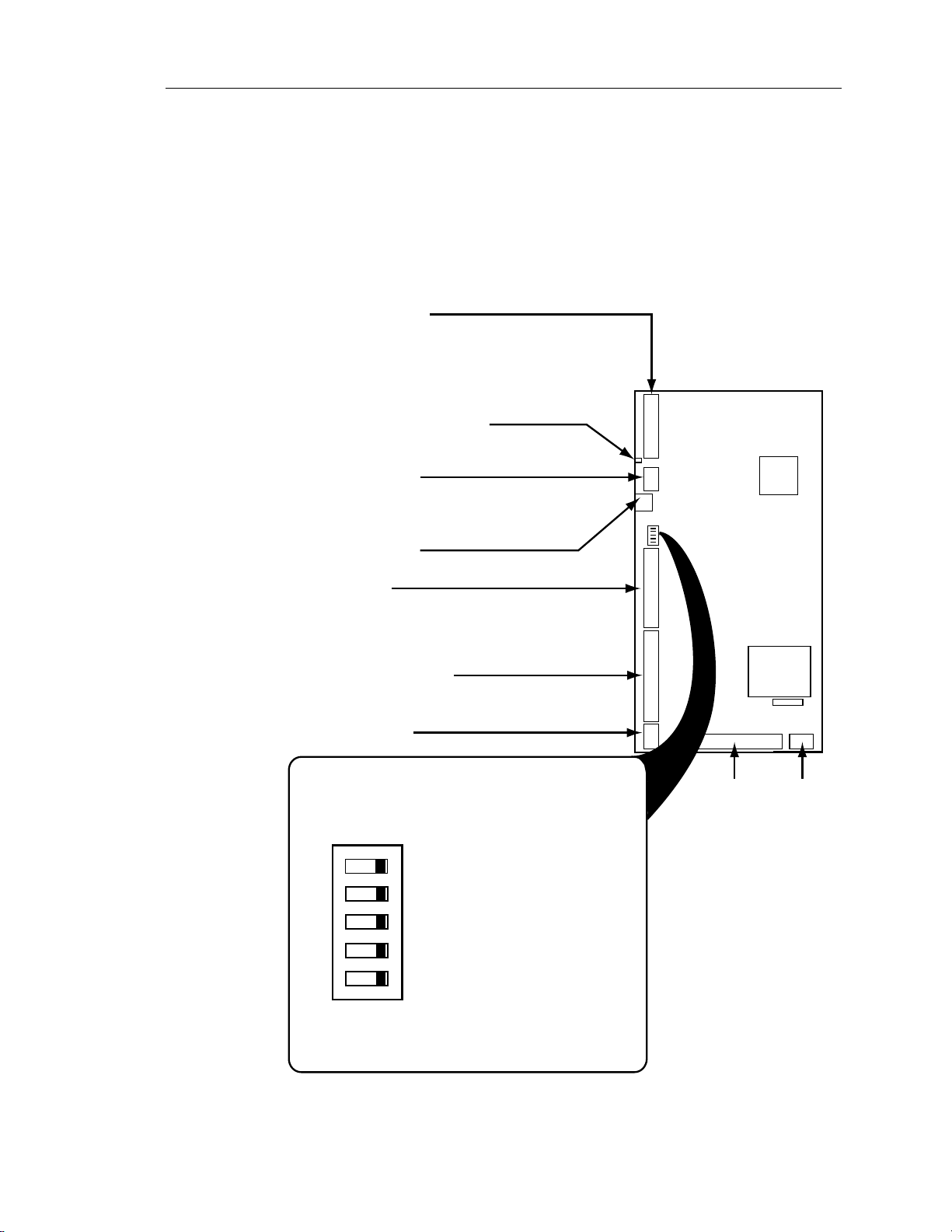
Controller Board
The Controller board is the foundation of the SED2 Electronic Bypass Option. It
controls communications to and from the SED2, keypad, isolated digital inputs,
relay/digital outputs, and contactors (Figure 3).
SED2 INTERFACE
Supports two SED2 non-isolated, digital relay
outputs and three SED2 digital inputs. The
maximum current draw for a relay output is 2 mA and
the voltage between the digital output source and return
lines is 24V. The Controller board provides unregulated,
non-isolated 24V to power the SED2 digital inputs.
BASIC SANITY TEST INDICATOR
Provides indication of initialization and
normal operation.
KEYPAD INTERFACE
Supports inputs and outputs from the Electronic
Bypass Option keypad. The keypad provides
user interface indicators and push buttons.
FACTORY USE ONLY
Connector J8 is for factory use only.
DIGITAL INPUTS
Supports six isolated digital inputs for customer use.
The inputs require a contact closure capable of
providing a low impedance path at currents less
than 20 mA.
DIGITAL RELAY OUTPUTS
Supports six digital relay outputs for customer use.
Each relay has a maximum rating of 2A at 120 Vac.
OVERRIDE JUMPER
Electronic Bypass Option Overview
J4
CONTROLLER
BOARD
SW1
J3
J8
ON
OFF
J2
J1
J6
MCU
TRANSFORMER
F1
J5J7
The Controller board DIP switches enable/disable
the Electronic Bypass Option features.
ON
5
OFF
Not used, factory test selector switch #2;
5
leave this switch OFF.
CONTACTOR
CONTROLS
POWER
Not used, factory test selector switch #1;
leave this switch OFF.
DIP SWITCHES
Interlock selector switch; requires
34
OPTIONS
34
SED2 programming.
Automatic Bypass selector switch;
requires SED2 programming.
12
ON
12
Essential Services selector switch.
SW1
When the switch is ON the option is enabled;
VFD0095R1
when the switch is OFF the option is disabled.
Figure 3. Controller Board Inputs and Outputs.
Siemens Building Technologies, Inc. 5
Page 14
SED2 VFD Electronic Bypass Option Operating Instructions
Contactors
The Controller board provides two or three relay contact circuits controlled by the
Electronic Bypass Option: bypass, input, and output contactors. Each circuit includes
a NO relay. Controller board connector J7 enables circuit connections. The relay
circuits route power to the SED2 and the motor via the contactors. Controlling the
contactors through the relay circuits is the main function of the Controller board.
Bypass Contactor – The bypass relay on the Controller board controls the bypass
contactor. The output and bypass relays are interconnected to 120 Vac Hot. This
enables a safety circuit that prevents the bypass and output contactors from
simultaneously being energized.
Output Contactor – The output relay on the Controller board controls the output
contactor.
Input Contactor – The input relay on the Controller board controls the optional input
contactor.
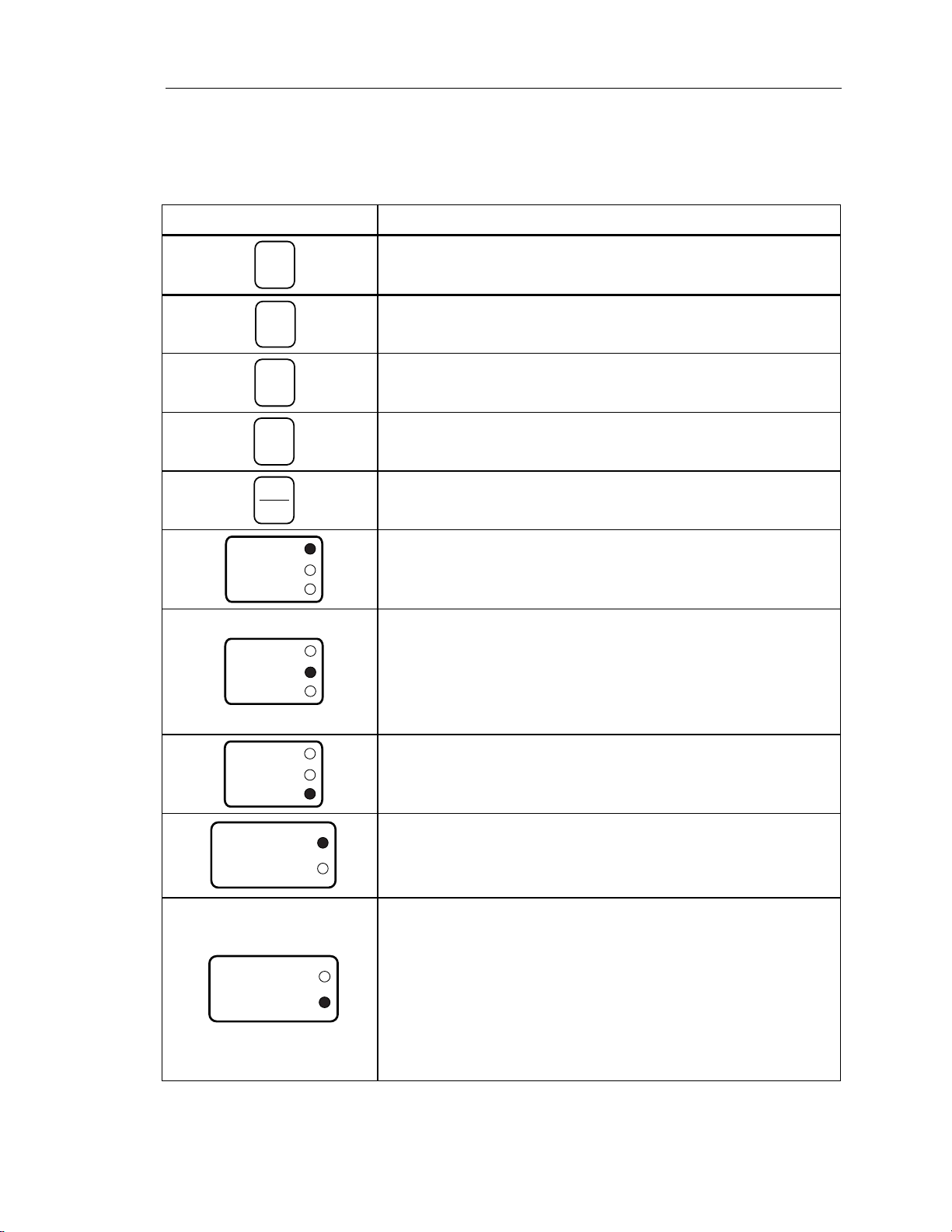
Keypad Functions
Input
Contactor
Bypass
Contactor
VFD
Enable
STOP
Auto Bypass Enabled
RESET
INTERLOCK START LOGIC
VFD0096R1
2-CONTACTOR KEYPAD
The keypad provides user interface indicators and pushbuttons. The following table
describes specific pushbutton and indicator functions:
Overload
Output
Contactor
Motor
Essential Services
Enable Commanded Proofed
Figure 4. E-Bypass Keypad Indicators and Pushbuttons.
Relay
Bypass
Hand
Start
Remote
VFD Fault
Safety Fault
Overload Fault
Start
VFD Bypass
Input
On/Off
Enable
STOP
RESET
INTERLOCK START LOGIC
VFD0097R1
Input
Contactor
VFD
Output
Contactor
Motor
Auto Bypass Enabled
Essential Services
Enable Commanded Proofed
Bypass
Contactor
Overload
Relay
Hand
Start
Remote
Start
VFD Fault
Safety Fault
Overload Fault
3-CONTACTOR KEYPAD
6 Siemens Building Technologies, Inc.
Page 15
Electronic Bypass Option Overview
Pushbutton/Indicator Description
Input
On/Off
VFD0098R1
Enable
VFD0099R1
Hand
Start
VFD0100R1
Remote
Start
VFD0101R1
STOP
RESET
VFD0102R1
VFD Fault
Safety Fault
Overload Fault
VFD0103R1
VFD Fault
Safety Fault
Overload Fault
VFD0104R1
The Input On/Off pushbutton is supplied with the optional drive input
contactor. In VFD mode, this switch does nothing. In bypass mode, this
switch closes/opens the input contactor, switching the SED2 power on/off.
Enables SED2 operation by closing the input and output contactors.
Manually enables bypass mode operation by ensuring that the output
contactor is open and then closing the bypass contactor.
Activates the bypass mode and operates the bypass contactor according
to the status of the Remote Start input on the Controller board.
Opens the output and bypass contactors, disconnecting the motor.
When a VFD Fault is indicated, the VFD Fault indicator lights and the
VFD Fault Relay output on the Controller Board is triggered.
The Safety Fault indicator lights when either of the Remote Safety inputs
on the Controller board opens. The motor is prohibited from operating in
either the VFD or bypass modes while either of these contacts is open.
EXCEPTION: Essential Services ignores a Safety Fault.
NOTE: If not using the Remote Safety feature, hard wire the two
Remote Safety inputs.
VFD Fault
Safety Fault
Overload Fault
VFD0105R1
If the Electronic Bypass Option current overload relay trips, the Overload
Fault indicator lights and the motor will not run in bypass mode.
When the Auto Bypass DIP switch is enabled, the Auto Bypass Enabled
Auto Bypass Enabled
Essential Services
VFD0106R1
indicator is on steady. Bypass operation is automatically initiated by the
SED2.
When Auto Bypass is active, the Auto Bypass Enabled indicator flashes.
When the Essential Services DIP switch is enabled, the Essential
Services indicator is on steady.
When the Essential Services input is open, normal operation is indicated
Auto Bypass Enabled
Essential Services
VFD0107R1
as the output contactor remains closed to keep the motor running and the
Essential Services indicator is on steady.
When the Essential Services input is closed, the bypass contactor closes
and the Essential Services indicator flashes.
Nothing can interrupt the Essential Services mode except for the
Essential Services input opening.
Siemens Building Technologies, Inc. 7
Page 16
SED2 VFD Electronic Bypass Option Operating Instructions
Pushbutton/Indicator Description
When the Interlock DIP switch is enabled, the Interlock Start Logic Enable
indicator is on steady. Any call to start the motor in either VFD or bypass
modes will not start the motor; instead it will close the Programmable
Output relay on the Controller board.
The Programmable Output can be used to actuate another device. When
this occurs, the Interlock Start Logic Commanded indicator also lights,
and the Interlock Start Logic Proofed indicator flashes.
A contact closure from this other device is wired to the Interlock Start on
the Controller board which then starts the motor and turns the Interlock
Start Logic Proofed indicator on steady. This feature is also called
damper end switch relay logic.
INTERLOCK START LOGIC
VFD0108R1
Enable Commanded Proofed
8 Siemens Building Technologies, Inc.
Page 17

Installation Instructions
Environmental Conditions
Install the Electronic Bypass Option in a heated, indoor controlled environment that is free of
moisture and conductive contaminants such as condensation and dust. The air entering the
unit for ventilation/cooling must be clean and free from corrosive gases.
The ambient temperature must be between 14°F and 104°F (-10°C to 40°C) and the relative
humidity must be 0% to 95% noncondensing. Do not mount unit in direct sunlight.
Mechanical Installation
Installation Instructions
Inspection
1. As you unpack the Electronic Bypass Option, check for shipping damage. In the event of
damage, contact the transport company.
2. Locate the Electronic Bypass Option nameplate and confirm that the unit is configured to
the installation requirements.
3. Verify the delivery is complete. If not, contact the supplier.
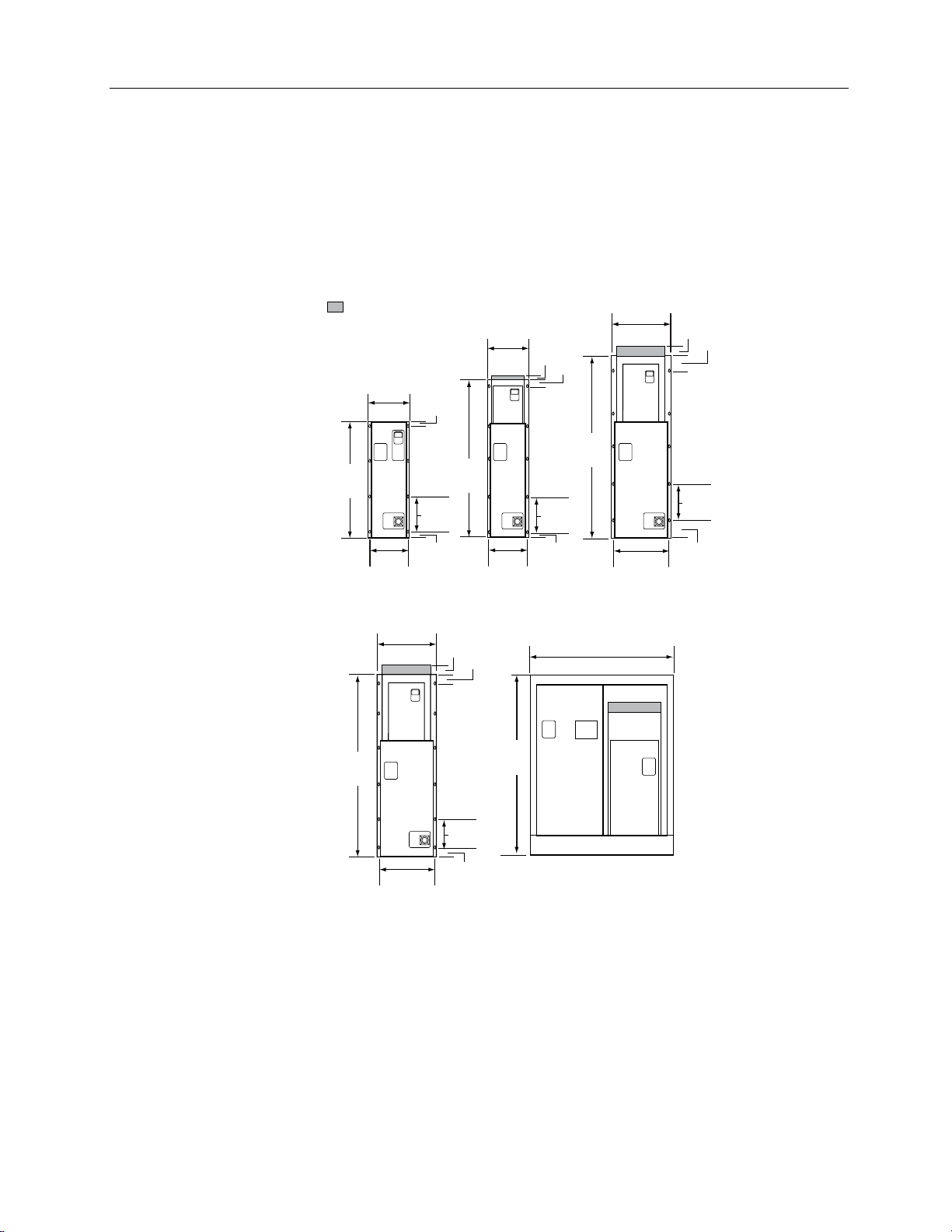
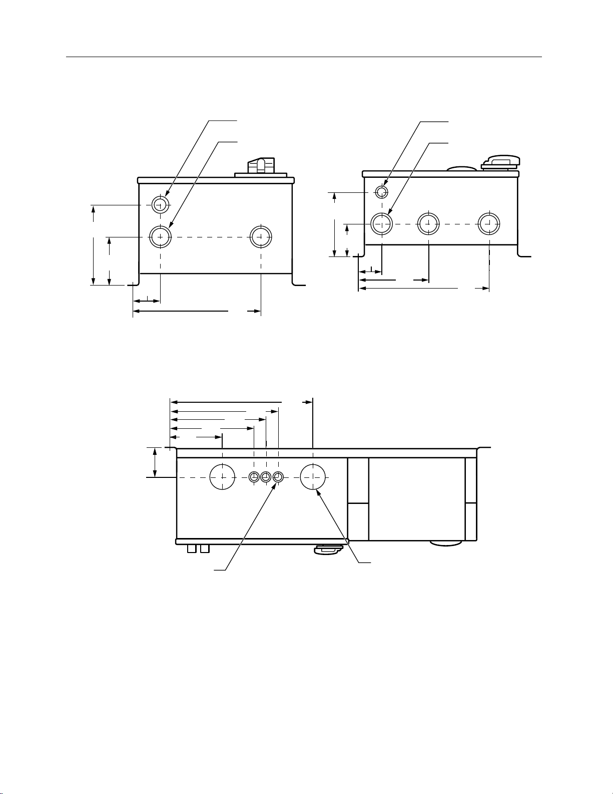
Dimensions and Weights
Figure 5 shows overall and mounting dimensions for the Electronic Bypass Option. Figures 6
through 8 show conduit locations.
Approximate weights are as follows.
Bypass
Frame Size
A 45 (20)
B 55 (25)
C 75 (34)
D 150 (68)
E 180 (82)
F 470 (213)
Weight lb (kg)
NOTE: Exact weight will be affected by actual horsepower/voltage and selected power
options.
Siemens Building Technologies, Inc. 9
Page 18
SED2 VFD Electronic Bypass Option Operating Instructions
Mounting
1. To ensure safe installation, verify that the surface of the mounting location is level.
2. Mount the Electronic Bypass Option vertically with the SED2 operator panel, Electronic
Bypass Option keypad, and disconnect accessible.
= Protective Shield
Depth
With
Handle
9.6 (24)
13.2
(34)
34
(86)
12.4
(31)
Frame Size
A and B
Depth
With
Handle
12.2 (31)
58.5
(149)
20.8
(53)
Depth
Handle
9.6 (24)
1.5
(3.8)
10.5 TYP
(27)
1.5
(3.8)
2.9
(7.4)
With
(122)
48
3
(7.6)
11.5
(29)
10.6
(27)
Frame
Size C
57.5
(146)
1
(2.5)
11 TYP
2
(5)
(28)
2
(5)
Depth
With
Handle
10.4 (26)
53.5
(136)
45.5
(116)
20.8
(53)
19.9
(51)
Frame
Size D
2.9
(7.4)
(10)
11.5 TYP
(29)
3.4
(8.6)
Depth
17.4
(44)
4
10 TYP
(25)
19.9
(51)
VFD0127R2
5.5
(14)
Frame Size FFrame Size E
NOTE: It is recommended to leave 6 inches (15 cm) around the top and sides of the unit.
Figure 5. E-Bypass Dimensions in Inches (Centimeters).
10 Siemens Building Technologies, Inc.
Page 19
Installation Instructions
S
S
6
(15.2)
3-5/8
(9.2)
2-1/8
(5.3)
VFD0201R1
Figure 6. Frame Sizes A through C Conduit
Locations. Viewed from Bottom;
Dimensions in Inches (Centimeters).
11-7/8
(30.1)
7-3/8
(18.7)
1/2 (1.3) AND 3/4 (1.9)
CONDUIT KNOCKOUT
3/4 (1.9) AND 1 (2.5)
CONDUIT KNOCKOUT
9-1/2
(24.1)
15-3/8
(39.1)
13-5/8
(34.6)
20-3/8
(51.7)
1/2 (1.3) AND 3/4 (1.9)
CONDUIT KNOCKOUTS
1-1/4 (3.2) AND 1-1/2 (3.8)
CONDUIT KNOCKOUTS (3)
8
(20.3)
4
(10.2)
2-3/4
(6.9)
8-1/2
(21.7)
VFD0202R1
16
(40.7)
Figure 7. Frame Sizes D and E Conduit Locations.
Viewed from Bottom;
Dimensions in Inches (Centimeters).
4-1/4
(10.8)
3/4 (1.9) AND 1 (2.5)
CONDUIT KNOCKOUTS (3)
VFD0203R1
3 (7.6) CONDUIT
KNOCKOUTS (2)
Figure 8. Frame Size F Conduit Locations. Viewed from Top; Dimensions in Inches (Centimeters).
Siemens Building Technologies, Inc. 11
Page 20

SED2 VFD Electronic Bypass Option Operating Instructions
Electrical Installation
See Figure 9 for all Electronic Bypass Option wiring.
1. Route shielded twisted pair (recommended wire type) cable, 24 gauge minimum control
wiring in conduit through knockout and into housing (Figures 10 through 12). Connect
control wiring per job-specific drawings.
NOTES:
• Terminate shield at control device.
• Control wiring is 12 to 26 AWG and tightening torque is 5 lb-in.
2. If applicable, route communications wiring (P1) in conduit through knockout and into
housing (Figures 10 through 12). Continue to route communications wiring to SED2 and
terminate per SED2 VFD Startup, Operation, and Maintenance Manual (125-3201).
3. Route motor wiring in conduit through knockout and into housing (Figures 10 through 12).
Connect motor wiring to motor overload and ground lug. See Tables 1 through 4 for wire
sizes and tightening torques.
4. Route input power wiring in conduit through knockout and into housing (Figures 10
through 12). Connect input power wiring to disconnect switch and ground lug or to circuit
breaker and ground lug. See Tables 1 through 4 for wire sizes and tightening torques.
12 Siemens Building Technologies, Inc.
Page 21

L1
POWER
L2
SUPPLY
3 PHASE
60 Hz
L3
GND
VFD0160R1
NOTES:
OPTIONAL SUPPLEMENTARY
POWER FUSES - MAIN SHORT
CIRCUIT PROTECTION BY OTHERS
DISC1
(T1)
(T3)
GND
LUG
(SEE NOTE 1)
1L1
(L1)
1L2
(L2)(T2)
1L3
(L3)
GND
1L1 1L2
TO
STEP-DOWN
CONTROL
TRANSFORMER
FU1
OPTIONAL
DRIVE INPUT
CONTACTOR
M3
3L1
(2)
(1)
3L2
(3)
(4)
3L3
(5)
(6)
2L1
2L2
2L3
OPTIONAL
INPUT LINE
REACTOR
A1
B1
Installation Instructions
M1
(5) (6)
(3) (4)
VFD
R
A2
S
B2
T
C2C1
L1
L2 V
U
WL3
GND
OPTIONAL
OUTPUT LOAD
REACTOR
U1
A1
V1
B1
W1
C1
(1) (2)
M2
U
(1) (2)
A2
V
(3)
W
(4)
(5) (6)
B2
C2
OL1
GND
LUG
(T1)
(T2)
(T3)
1T1
1T2
1T3
M
AC MOTOR
(CUSTOMER
SUPPLIED)
1. Branch circuit protection to be provided by installer, per UL508A, if not provided with drive.
2. For bypass operation, modify these drive parameters: P0702[0] and P0702[1] = 3,
P0748 = Digital Out 1 Reverse (
).
3. Control and communication wiring should be 300V UL minimum.
4. Communication wiring should be run with maximum separation possible from all other
wiring.
5. Essential service mode operates the motor full speed (bypass) with no protection for the
motor or system.
6. Ensure that automatic bypass will not damage the system before activating.
7. See Table 8 for proper fuse and wire sizes.
8. See Siemens Publication No. 125-3201 for SED2 input/output control signal wiring details.
Figure 9. E-Bypass Power Circuit.
Siemens Building Technologies, Inc. 13
Page 22

SED2 VFD Electronic Bypass Option Operating Instructions
SED2 VFD
CONTROLLER
BOARD
J2
CONTROL WIRING
(DIGITAL INPUTS/
OUTPUTS) VIA
2 KNOCKOUTS
TRANSFORMER
OUTPUT
CONTACTOR
BYPASS
CONTACTOR
MOTOR
OVERLOAD
MOTOR
WIRING
VIA
KNOCKOUT
VFD0111R2
T1 T2 T3
J1
L1 L2 L3
Figure 10. Routing of Power and Control Wiring
for Frame Sizes A and B.
COMMUNICATIONS
WIRING (P1) VIA
INPUT
CONTACTOR
(OPTIONAL)
REACTOR
(OPTIONAL)
POWER FUSES
(OPTIONAL)
GROUND LUGS
DISCONNECT
(OR OPTIONAL
CIRCUIT BREAKER)
INPUT
POWER
WIRING VIA
KNOCKOUT
1 KNOCKOUT
SWITCH
SED2 VFD
CONTROLLER
BOARD
J2
CONTROL WIRING
(DIGITAL INPUTS/
OUTPUTS) VIA
2 KNOCKOUTS
TRANSFORMER
VFD0112R1
OUTPUT
CONTACTOR
BYPASS
CONTACTOR
MOTOR
OVERLOAD
MOTOR
WIRING
VIA
KNOCKOUT
J1
L1 L2 L3T1 T2 T3
WIRING VIA
KNOCKOUT
Figure 11. Routing of Power and Control
Wiring for Frame Sizes C, D, and E.
COMMUNICATIONS
WIRING (P1) VIA
1 KNOCKOUT
INPUT
CONTACTOR
(OPTIONAL)
REAC TOR
(OPTIONAL)
POWER FUSES
(OPTIONAL)
GROUND LUGS
DISCONNECT
SWITCH
(OR OPTIONAL
CIRCUIT BREAKER)
INPUT
POWER
MOTOR
WIRING VIA
KNOCKOUT
DISCONNECT SWITCH
(OR OPTIONAL
CIRCUIT BREAKER)
MOTOR
OVERLOAD
BYPASS
CONTACTOR
OUTPUT
CONTACTOR
CONTROLLER
BOARD
TRANSFORMER
INPUT
CONTACTOR
(OPTIONAL)
POWER FUSES
(OPTIONAL)
VFD0113R1
GROUND
LUGS (2)
T3 T2 T1
J2
J1
L3 L2 L1
INPUT POWER
WIRING VIA
KNOCKOUT
REACTOR
(OPTIONAL)
SED2
VFD
COMMUNICATIONS
WIRING (P1) VIA
1 KNOCKOUT
Figure 12. Routing of Power and Control Wiring for Frame Size F.
14 Siemens Building Technologies, Inc.
Page 23

Installation Instructions
Table 1. Wire Sizes and Tightening Torques for E-Bypass wi th 208V Drive.
Circuit Breaker
Part
Number
Bypass
Frame
Size
HP kW Amps
Size *
VBE10.5---- A 0.5 0.37 2.3
VBE10.7---- A 0.7 0.55 3.0
VBE11.0---- A 1.0 0.75 3.9
VBE11.5---- B 1.5 1.1 5.5
VBE12.0---- B 2.0 1.5 7.4
VBE13.0---- B 3.0 2.2 10.4
VBE15.0---- C 5.0 4.0 16.7
VBE17.5---- C 7.5 5.5 22.0
VBE110.---- C 10 7.5 28
VBE115.---- D 15 11.0 42
VBE120.---- D 20 15.0 54
VBE125.---- D 25 18.5 68
VBE130.---- E 30 22.0 80
VBE140.---- F 40 30.0 104
VBE150.---- F 50 37.0 130
VBE160.---- F 60 45.0 154
3-3/0-3
3-3/0-3
6 - 350
6 - 350
6 - 350
Wire
14-10
Cu
14-10
Cu
14-10
Cu
14-10
Cu
14-10
Cu
14-10
Cu
14-10
Cu
14-10
Cu
10-1/0
Cu
10-1/0
Cu
10-1/0
Cu
Cu
Cu
kcmil
Cu
kcmil
Cu
kcmil
Cu
Torque,
lb-in
(Nm)
32 (3.6) 18-10
32 (3.6) 18-10
32 (3.6) 18-10
32 (3.6) 18-10
32 (3.6) 18-10
32 (3.6) 18-10
32 (3.6) 14-8
20 - 60
(2.2 - 6.8)
20 - 60
(2.2 - 6.8)
20 - 60
(2.2 - 6.8)
20 - 60
(2.2 - 6.8)
80 (9) 12-1
80 (9) 12-1
120 - 275
(14 - 31.1)
120 - 275
(14 - 31.1)
120 - 275
(14 - 31.1)
Disconnect
Switch
Wire
Size *
14-8
14-8
14-6
12-1
12-1
6 - 350
(13.5 - 31.1)
kcmil
6 - 350
(13.5 - 31.1)
kcmil
Torque,
lb-in
(Nm)
13 -
(1.5 - 1.7)
13 -
(1.5 - 1.7)
13 - 17
(1.5 - 1.7)
13 -
(1.5 - 1.7)
13 -
(1.5 - 1.7)
13 - 17
(1.5 - 1.7)
17 - 22
(1.9 - 2.5)
17 - 22
(1.9 - 2.5)
17 - 22
(1.9 - 2.5)
22 - 27
(2.5 - 3.1)
22 - 27
(2.5 - 3.1)
22 - 27
(2.5 - 3.1)
22 - 27
(2.5 - 3.1)
22 - 27
(2.5 - 3.1)
120 - 275
120 - 275
Wire
Size *
18-14
18-14
18-14
18-14
18-14
18-14
14-10
14-10
18-3
18-3
10-1/0
10-1/0
10-1/0
6-3/0
6-3/0
6-3/0
Overload Ground Lug
Torque,
lb-in
(Nm)
7 - 10.3
(8 - 1.2)
7 - 10.3
(8 - 1.2)
7 - 10.3
(8 - 1.2)
7 - 10.3
(8 - 1.2)
7 - 10.3
(8 - 1.2)
7 - 10.3
(8 - 1.2)
18 - 22
(2 - 25)
18 - 22
(2 - 25)
27 - 40
(3.1 - 4.5)
27 - 40
(3.1 - 4.5)
36 - 53
(4.1 - 6)
36 - 53
(4.1 - 6)
36 - 53
(4.1 - 6)
124 - 210
(14 - 23.7)
124 - 210
(14 - 23.7)
124 - 210
(14 - 23.7)
Range,
Amps
1.8 - 2.5 10 14-2 35 (4)
2.2 - 3.2 12 14-2 35 (4)
2.8 - 4 16 14-2 35 (4)
4.5 - 6.3 25 14-2 35 (4)
5.5 - 8.0 30 14-2 35 (4)
7 - 10 40 14-2 35 (4)
14 - 20 80 14-2 35 (4)
20 - 25 100 14-2 35 (4)
22 - 32 125 14-2 35 (4)
40 - 50 200 14-2 35 (4)
45 - 63 250 14-2 35 (4)
57 - 75 300 14-2 35 (4)
70 - 90 350 14-2 35 (4)
50 - 200 800 14-2/0 50 (5.6)
50 - 200 800 14-2/0 50 (5.6)
50 - 200 800 14-2/0 50 (5.6)
Max
Backup
Fuse,
Amps
Wire
Size *
Torque,
lb-in
(Nm)
* Wire size is AWG unless noted otherwise. Use Copper (Cu) wire that is rated 167°F (75°C) minimum
600 Vac.
Siemens Building Technologies, Inc. 15
Page 24

SED2 VFD Electronic Bypass Option Operating Instructions
Table 2. Wire Sizes and Tightening Torques for E-Bypass with 230V to 240V Drive.
Circuit Breaker
Part
Number
Bypass
Frame
Size
HP kW Amps
Size *
VBE20.5---- A 0.5 0.37 2.2
VBE20.7---- A 0.7 0.55 3.0
VBE21.0---- A 1.0 0.75 3.9
VBE21.5---- B 1.5 1.1 5.5
VBE22.0---- B 2.0 1.5 6.8
VBE23.0---- B 3.0 2.2 9.6
VBE25.0---- C 5.0 4.0 15.2
VBE27.5---- C 7.5 5.5 22
VBE210---- C 10 7.5 28
VBE215---- D 15 11.0 42
VBE220---- D 20 15.0 54
VBE225---- D 25 18.5 68
VBE230---- E 30 22.0 80
VBE240---- F 40 30.0 104
VBE250---- F 50 37.0 130
VBE260---- F 60 45.0 154
3-3/0-3
3-3/0-3
6 - 350
6 - 350
6 - 350
Wire
14-10
Cu
14-10
Cu
14-10
Cu
14-10
Cu
14-10
Cu
14-10
Cu
14-10
Cu
14-10
Cu
10-1/0
Cu
10-1/0
Cu
10-1/0
Cu
Cu
Cu
kcmil
Cu
kcmil
Cu
kcmil
Cu
Torque,
lb-in
(Nm)
32 (3.6) 18-10
32 (3.6) 18-10
32 (3.6) 18-10
32 (3.6) 18-10
32 (3.6) 18-10
32 (3.6) 18-10
32 (3.6) 14-8
20 - 60
(2.2 - 6.8)
20 - 60
(2.2 - 6.8)
20 - 60
(2.2 - 6.8)
20 - 60
(2.2 - 6.8)
80 (9) 12-1
80 (9) 12-1
120 - 275
(14 - 31.1)
120 - 275
(14 - 31.1)
120 - 275
(14 - 31.1)
Disconnect
Switch
Wire
Size *
14-8
14-8
14-6
12-1
12-1
6 - 350
kcmil
6 - 350
kcmil
Torque,
lb-in
(Nm)
13 -
(1.5 - 1.7)
13 -
(1.5 - 1.7)
13 -
(1.5 - 1.7)
13 -
(1.5 - 1.7)
13 -
(1.5 - 1.7)
13 -
(1.5 - 1.7)
17 - 22
(1.9 - 2.5)
17 - 22
(1.9 - 2.5)
17 - 22
(1.9 - 2.5)
22 - 27
(2.5 - 3.1)
22 - 27
(2.5 - 3.1)
22 - 27
(2.5 - 3.1)
22 - 27
(2.5 - 3.1)
22 - 27
(2.5 - 3.1)
120 - 275
(13.5 - 31.1)
120 - 275
(13.5 - 31.1)
Wire
Size *
18-14
18-14
18-14
18-14
18-14
18-14
14-10
14-10
18-3
18-3
10-1/0
10-1/0
10-1/0
6-3/0
6-3/0
6-3/0
Overload Ground Lug
Torque,
lb-in
(Nm)
7 - 10.3
(8 - 1.2)
7 - 10.3
(8 - 1.2)
7 - 10.3
(8 - 1.2)
7 - 10.3
(8 - 1.2)
7 - 10.3
(8 - 1.2)
7 - 10.3
(8 - 1.2)
18 - 22
(2 - 25)
18 - 22
(2 - 25)
27 - 40
(3.1 - 4.5)
27 - 40
(3.1 - 4.5)
36 - 53
(4.1 - 6)
36 - 53
(4.1 - 6)
36 - 53
(4.1 - 6)
124 - 210
(14 - 23.7)
124 - 210
(14 - 23.7)
124 - 210
(14 - 23.7)
Range,
Amps
1.8 - 2.5 10 14-2 35 (4)
2.2 - 3.2 12 14-2 35 (4)
2.8 - 4 16 14-2 35 (4)
4.5 - 6.3 25 14-2 35 (4)
5.5 - 8.0 30 14-2 35 (4)
7 - 10 40 14-2 35 (4)
14 - 20 80 14-2 35 (4)
20 - 25 100 14-2 35 (4)
22 - 32 125 14-2 35 (4)
40 - 50 200 14-2 35 (4)
45 - 63 250 14-2 35 (4)
57 - 75 300 14-2 35 (4)
70 - 90 350 14-2 35 (4)
50 - 200 800 14-2/0 50 (5.6)
50 - 200 800 14-2/0 50 (5.6)
50 - 200 800 14-2/0 50 (5.6)
Max
Backup
Fuse,
Amps
Wire
Size *
Torque,
* Wire size is AWG unless noted otherwise. Use Copper (Cu) wire that is rated 167°F (75°C) minimum
600 Vac.
lb-in
(Nm)
16 Siemens Building Technologies, Inc.
Page 25

Installation Instructions
Table 3. Wire Sizes and Tightening Torques for E-Bypass with 380V to 480V Drive.
Circuit Breaker
Part
Number
Bypass
Frame
Size
HP kW Amps
Size *
VBE30.5---- A 0.5 0.37 1.1
VBE30.7---- A 0.7 0.55 1.6
VBE31.0---- A 1.0 0.75 2.1
VBE31.5---- A 1.5 1.1 3.0
VBE32.0---- A 2.0 1.5 3.4
VBE33.0---- B 3.0 2.2 4.8
VBE35.0---- B 5.0 4.0 7.6
VBE37.5---- C 7.5 5.5 11
VBE310---- C 10 7.5 14
VBE315---- C 15 11.0 21
VBE320---- C 20 15.0 27
VBE325---- D 25 18.5 34
VBE330---- D 30 22.0 40
VBE340---- D 40 30.0 52
VBE350---- E 50 37.0 65
VBE360---- E 60 45.0 77
VBE375---- F 75 55.0 96
VBE3100---- F 100 75.0 124
VBE3125---- F 125 90.0 156
VBE3125--
HA
F — 90.0 178
10-1/0
10-1/0
10-1/0
10-1/0
10-1/0
6 - 350
6 - 350
6 - 350
Wire
14-10
Cu
14-10
Cu
14-10
Cu
14-10
Cu
14-10
Cu
14-10
Cu
14-10
Cu
14-10
Cu
14-10
Cu
14-10
Cu
Cu
Cu
Cu
Cu
Cu
3-3/0
Cu
3-3/0
Cu
kcmil
Cu
kcmil
Cu
kcmil
Cu
Torque,
lb-in
(Nm)
32 (3.6) 18-10
32 (3.6) 18-10
32 (3.6) 18-10
32 (3.6) 18-10
32 (3.6) 18-10
32 (3.6) 18-10
32 (3.6) 18-10
32 (3.6) 18-10
32 (3.6) 18-10
20 - 60
(2.2 - 6.8)
20 - 60
(2.2 - 6.8)
20 - 60
(2.2 - 6.8)
20 - 60
(2.2 - 6.8)
20 - 60
(2.2 - 6.8)
20 - 60
(2.2 - 6.8)
80 (9) 12-1
80 (9) 12-1
120 - 275
(14 - 31.1)
120 - 275
(14 - 31.1)
120 - 275
(14 - 31.1)
Disconnect
Switch
Wire
Size *
14-8
14-8
14-6
14-6
14-6
12-1
6 - 350
kcmil
(13.5 - 31.1)
6 - 350
kcmil
(13.5 - 31.1)
6 - 350
kcmil
(13.5 - 31.1)
Torque,
lb-in
(Nm)
13 - 17
(1.5 - 1.7)
13 - 17
(1.5 - 1.7)
13 - 17
(1.5 - 1.7)
13 - 17
(1.5 - 1.7)
13 - 17
(1.5 - 1.7)
13 - 17
(1.5 - 1.7)
13 - 17
(1.5 - 1.7)
13 - 17
(1.5 - 1.7)
13 to17
(1.5 - 1.7)
17 - 22
(1.9 - 2.5)
17 - 22
(1.9 - 2.5)
22 - 27
(2.5 - 3.1)
22 - 27
(2.5 - 3.1)
22 - 27
(2.5 - 3.1)
22 - 27
(2.5 - 3.1)
22 - 27
(2.5 - 3.1)
22 - 27
(2.5 - 3.1)
120 - 275
120 - 275
120 - 275
Wire
Size *
18-14
18-14
18-14
18-14
18-14
18-14
18-14
18-14
14-10
14-10
18-3
18-3
18-3
18-3
10-1/0
10-1/0
10-1/0
6-3/0
6-3/0
6-3/0
Overload Ground Lug
Torque,
lb-in
(Nm)
7 - 10.3
(8 - 1.2)
7 - 10.3
(8 - 1.2)
7 - 10.3
(8 - 1.2)
7 - 10.3
(8 - 1.2)
7 - 10.3
(8 - 1.2)
7 - 10.3
(8 - 1.2)
7 - 10.3
(.8 - 1.2)
7 - 10.3
(8 - 1.2)
18 - 22
(2 - 2.5)
18 - 22
(2 - 2.5)
27 - 40
(3.1 - 4.5)
27 - 40
(3.1 - 4.5)
27 - 40
(3.1 - 4.5)
27 - 40
(3.1 - 4.5)
36 - 53
(4.1 - 6)
36 - 53
(4.1 - 6)
36 - 53
(4.1 - 6)
124 - 210
(14 - 23.7)
124 - 210
(14 - 23.7)
124 - 210
(14 - 23.7)
Range,
Amps
.7 - 1.0
1.1 - 1.6
1.4 - 2.0
2.2 - 3.2
2.8 - 4
3.5 - 5
7 - 10
9 - 12
11 - 16
17 - 22
22 - 32
28 - 40
28 - 40
40 - 50
57 - 75
70 - 90
80 - 100
50 - 200 800 14-2/0 50 (5.6)
50 - 200 800 14-2/0 50 (5.6)
50 - 200 800 14-2/0 50 (5.6)
Max
Backup
Fuse,
Wire
Size*
Amps
4 14-2 35 (4)
6 14-2 35 (4)
8 14-2 35 (4)
12 14-2 35 (4)
16 14-2 35 (4)
20 14-2 35 (4)
40 14-2 35 (4)
45 14-2 35 (4)
60 14-2 35 (4)
80 14-2 35 (4)
125 14-2 35 (4)
150 14-2 35 (4)
150 14-2 35 (4)
200 14-2 35 (4)
300 14-2 35 (4)
350 14-2 35 (4)
400 14-2/0 50 (5.6)
* Wire size is AWG unless noted otherwise. Use Copper (Cu) wire that is rated 167°F (75°C) minimum
600 Vac.
Torque,
lb-in
(Nm)
Siemens Building Technologies, Inc. 17
Page 26

SED2 VFD Electronic Bypass Option Operating Instructions
Table 4. Wire Sizes and Tightening Torques for E-Bypass with 500V to 600V Drive.
Circuit Breaker
Part
Number
Bypass
Frame
Size
HP kW Amps
Size *
VBE40.5---- C 0.5 0.37 .9
VBE40.7---- C 0.7 0.55 1.3
VBE41.0---- C 1.0 0.75 1.4
VBE41.5---- C 1.5 1.1 2.1
VBE42.0---- C 2.0 1.5 2.7
VBE43.0---- C 3.0 2.2 3.9
VBE45.0---- C 5.0 4.0 6.1
VBE47.5---- C 7.5 5.5 9
VBE410.---- C 10 7.5 11
VBE415.---- C 15 11.0 17
VBE420.---- C 20 15.0 22
VBE425.---- C 25 18.5 27
VBE430.---- D 30 22.0 32
VBE440.---- D 40 30.0 41
VBE450.---- E 50 37.0 52
VBE460.---- E 60 45.0 62
VBE475.---- F 75 55.0 77
VBE4100---- F 100 75.0 99
VBE4125---- F 125 90.0 125
10-1/0
10-1/0
10-1/0
10-1/0
10-1/0
10-1/0
6 - 350
Wire
14-10
Cu
14-10
Cu
14-10
Cu
14-10
Cu
14-10
Cu
14-10
Cu
14-10
Cu
14-10
Cu
14-10
Cu
14-10
Cu
Cu
Cu
Cu
Cu
Cu
Cu
3-3/0
Cu
3-3/0
Cu
kcmil
Cu
Torque,
lb-in
(Nm)
32 (3.6) 18-10
32 (3.6) 18-10
32 (3.6) 18-10
32 (3.6) 18-10
32 (3.6) 18-10
32 (3.6) 18-10
32 (3.6) 18-10
32 (3.6) 18-10
32 (3.6) 18-10
32 (3.6) 14-8
20 - 60
(2.2 - 6.8)
20 - 60
(2.2 - 6.8)
20 - 60
(2.2 - 6.8)
20 - 60
(2.2 - 6.8)
20 - 60
(2.2 - 6.8)
20 - 60
(2.2 - 6.8)
80 (9) 12-1
80 (9) 12-1
120 - 275
(14 - 31.1)
Disconnect
Switch
Wire
Size *
14-8
14-6
14-6
14-6
14-6
12-1
6 - 350
kcmil
Torque,
lb-in
(Nm)
13 - 17
(1.5 - 1.7)
13 - 17
(1.5 - 1.7)
13 - 17
(1.5 - 1.7)
13 - 17
(1.5 - 1.7)
13 - 17
(1.5 - 1.7)
13 - 17
(1.5 - 1.7)
13 - 17
(1.5 - 1.7)
13 - 17
(1.5 - 1.7)
13 - 17
(1.5 - 1.7)
17 - 22
(1.9 - 2.5)
17 - 22
(1.9 - 2.5)
22 - 27
(2.5 - 3.1)
22 - 27
(2.5 - 3.1)
22 - 27
(2.5 - 3.1)
22 - 27
(2.5 - 3.1)
22 - 27
(2.5 - 3.1)
22 - 27
(2.5 - 3.1)
22 - 27
(2.5 - 3.1)
120 - 275
(14 - 31.1)
Wire
Size *
18-14
18-14
18-14
18-14
18-14
18-14
18-14
18-14
18-14
14-10
14-10
18-3
18-3
18-3
18-3
10-1/0
10-1/0
10-1/0
10-1/0
Overload Ground Lug
Torque,
lb-in
(Nm)
7 - 10.3
(8 - 1.2)
7 - 10.3
(8 - 1.2)
7 - 10.3
(8 - 1.2)
7 - 10.3
(8 - 1.2)
7 - 10.3
(8 - 1.2)
7 - 10.3
(8 - 1.2)
7 - 10.3
(8 - 1.2)
7 - 10.3
(8 - 1.2)
7 - 10.3
(8 - 1.2)
18 - 22
(2 - 2.5)
18 - 22
(2 - 2.5)
27 - 40
(3.1 - 4.5)
27 - 40
(3.1 - 4.5)
27 - 40
(3.1 - 4.5)
27 - 40
(3.1 - 4.5)
36 - 53
(4.1 - 6)
36 - 53
(4.1 - 6)
36 - 53
(4.1 - 6)
124 - 210
(14 - 23.7)
Range,
Amps
.7 - 1.0 4 14-2 35 (4)
.9 - 1.25 5 14-2 35 (4)
1.1 - 1.6 6 14-2 35 (4)
1.8 - 2.5 10 14-2 35 (4)
2.2 - 3.2 12 14-2 35 (4)
2.8 - 4 16 14-2 35 (4)
4.5 - 6.3 25 14-2 35 (4)
7 - 10 40 14-2 35 (4)
9 - 2 45 14-2 35 (4)
14 - 20 80 14-2 35 (4)
17 - 22 80 14-2 35 (4)
22 - 32 125 14-2 35 (4)
28 - 40 150 14-2 35 (4)
36 - 45 175 14-2 35 (4)
40 - 50 200 14-2 35 (4)
45 - 63 250 14-2 35 (4)
70 - 90 350 14-2/0 50 (5.6)
80 - 100 400 14-2/0 50 (5.6)
50 - 200 800 14-2/0 50 (5.6)
Max
Backup
Fuse,
Amps
Wire
Size*
Torque,
* Wire size is AWG unless noted otherwise. Use Copper (Cu) wire that is rated 167°F (75°C) minimum
600 Vac.
lb-in
(Nm)
18 Siemens Building Technologies, Inc.
Page 27

Startup Procedures
Safety Precautions
WARNING:
When you connect input power to the Electronic Bypass Option, the motor terminals
are energized even if the motor is not running. Do not make any connections with
input power connected to the Electronic Bypass Option. Disconnect and lock out
power to the drive before servicing it. Failure to disconnect input power may cause
serious injury or death.
CAUTION:
Startup Procedures
After you disconnect input power, the DC bus capacitors must be allowed to
discharge to a safe voltage. This will take about 5 minutes.
Installation Inspection
Inspect the mechanical and electrical installation for compliance with local electrical
codes and regulations. After installation, verify that:
• Electronic Bypass Option and motor are properly grounded.
• Input power and motor wire sizes are correct and connections are secure.
• Control wiring is correct, connections are secure, and wire shield is properly
grounded.
• Control wiring is not routed with power wiring.
• Electronic Bypass Option has proper ventilation.
• Internal Bypass connections are secure.
Power-On
1. Turn on Electronic Bypass Option power.
Power-on initialization performs a basic sanity test (approximately 7 seconds) to
initialize the Controller board. Also, the Stop/Reset indicator will flash.
A unit fault condition occurs if the Electronic Bypass Option did not pass the
basic sanity test. See the Troubleshooting section in this manual for more details.
Siemens Building Technologies, Inc. 19
Page 28

SED2 VFD Electronic Bypass Option Operating Instructions
After the basic sanity test, if the DIP switches have not changed and there is no
operator intervention, the most recent bypass function is restored. If the DIP
switches have changed, the Electronic Bypass Option activates the Stop/Reset
function.
2. Press the Enable key on the Electronic Bypass Option keypad to place the unit
in VFD mode.
3. Perform SED2 commissioning per the SED2 VFD Startup, Operation, and
Maintenance Manual (125-3201). If using the Quick Commissioning mode, end
this mode with P3900 = 3 to run a motor calculation without resetting the SED2 to
factory defaults.
4. After basic SED2 operation is established and verified, turn SED2 power off via
the Electronic Bypass Option input power device and verify that no dangerous
voltages are present in the enclosure.
5. Select Electronic Bypass Option application features using the DIP switches.
DIP Switch Settings for E-Bypass Features.
Switch
Position
1 Essential Services selector switch.
2 Automatic Bypass selector switch; requires SED2 programming.
3 Interlock selector switch; requires SED2 programming.
4 Factory test #1 selector switch. Not used; leave this switch OFF.
5 Factory test #2 selector switch. Not used; leave this switch OFF.
Description
NOTE: When the switch is ON, the feature is enabled; when the switch is
OFF, the feature is disabled. For details on the Electronic Bypass
Option features, see the Application Feature Setup section in this
manual.
6. Re-apply power to the Electronic Bypass Option. On units with three contactors,
energize the SED2 by pressing the Input pushbutton on the Electronic Bypass
Option keypad.
7. Program the SED2 per the Application Feature Setup section in this manual.
8. Test all SED2 and bypass features.
20 Siemens Building Technologies, Inc.
Page 29

9. If motor rotation is incorrect in either VFD, bypass, or both modes, have the
appropriate site personnel take corrective action as follows:
− Wrong Rotation in Bypass, Right in VFD Mode – Swap two input
leads on the main input device of the Electronic Bypass Option.
− Wrong Rotation in VFD, Right in Bypass Mode – Swap two input
leads on the main input device of the Electronic Bypass Option and swap
two motor leads at the motor overload in the Electronic Bypass Option.
− Wrong Rotation in both VFD and Bypass Modes – Swap two motor
leads at the motor overload in the Electronic Bypass Option.
Quick Commissioning
Parameter P0010 is the Commissioning Parameter Filter. It allows you to select a
group of parameters that can be used for quick commissioning, including motor data,
and motor ramp-up and ramp-down settings.
Startup Procedures
It is important to use parameter P0010 to commission the SED2, parameter P0003 to
select the access level for using parameters, and parameter P0004 to filter the
parameters according to their functionality. When Commissioning Parameter Filter
P0010 = 1, it initiates the quick commissioning procedure.
It is recommended that you use the quick commissioning procedure. However,
experienced users may commission the equipment without the P0004 filter functions.
At the end of the quick commissioning procedure, set parameter P3900 = 3. This
setting performs the necessary motor calculations and sets all remaining parameters
(those not included in P0010 = 1) to the factory default values. If 3900 is set to a
value greater than 0, P0010 is automatically reset to 0. (If P0010 = 1, the SED2
cannot start.) The process of performing motor calculations and setting all
parameters to factory default values is only possible via quick commissioning.
Siemens Building Technologies, Inc. 21
Page 30

SED2 VFD Electronic Bypass Option Operating Instructions
Parameter Description Action
Setting/
Default
P0003
NOTE:
Before starting quick commissioning, set P0003 = 3 to ensure all necessary parameters are available
during quick commissioning.
P0010
User Access Level
Allows you to access more
parameters.
1 = Standard
2 = Extended
3 = Expert
Quick Commissioning
0 = Ready to Run
1 = Quick Commissioning
30 = Factory Setting
1. Press
r0000 and to enter the SED2
parameter mode.
2. Press
parameter P0003.
3. Press
parameter values level.
4. Press
(expert level).
5. Press
the P0003 = 3 setting.
1. Press to access parameter
r0000 and to enter the SED2
parameter mode.
2. Repeatedly press
advance to parameter P0010.
to access parameter
to advance to
to access the
to advance to 3
to confirm and save
to
Setting = 3
Default = 1
Setting = 1
Default = 0
3. Press
parameter values level.
4. Press
5. Press to confirm and save
the P0010 = 1 setting.
NOTES:
1. P0010 must always be set back to 0 before operating the motor.
2. If P3900 is greater than 0 on completion of commissioning, P0010 is automatically set back to 0.
to access the
to advance to 1.
22 Siemens Building Technologies, Inc.
Page 31

Parameter Description Action
P0100
Operation for Europe/N.
America
0 = 50 Hz, kW (Europe)
factory default
1 = 60 Hz, hp
(North America)
2 = 60 Hz, kW
(North America)
The setting of Motor Frequency
and Unit of Measurement DIP
switch 2 overrides P0100
settings 0 and 1.
1. Press
parameter P0100.
2 Press
parameter values level.
3. Press
4. Press
the P0100 = 1 setting.
to advance to
to access the
to advance to 1.
to confirm and save
Startup Procedures
Setting/
Default
Setting = 1
Default = 0 or
1
(Default is
determined by
the setting of
the motor
frequency and
unit of
measurement
DIP switches.)
NOTES:
1. Stop the SED2 (that is, disable all pulses) before changing this parameter.
2. Changing P0100 resets all rated motor parameters as well as other parameters that depend on the
rated motor parameters (such as P0340, Calculation of motor Parameters).
P0304*
* Motor related parameters.
Rated Motor Voltage
10V to 2000V.
Rated motor voltage (V) from
motor nameplate.
1. Press
parameter P0304.
2. Press to access the
parameter values level.
3. Press
nominal voltage.
4. Press to confirm and save
the setting.
to advance to
to advance to
Setting =
Motor
nameplate
Default =
Varies by
model
Siemens Building Technologies, Inc. 23
Page 32

SED2 VFD Electronic Bypass Option Operating Instructions
Parameter Description Action
P0305*
Rated Motor Current
0A to 10,000A.
1. Press
parameter P0305.
to advance to
Setting/
Default
Setting =
Motor
nameplate
P0307*
P0308*, or
P0309
Rated motor current (A) from
motor nameplate.
Rated Motor Power
0 kW or hp to 200 kW or hp.
Rated motor power (kW or hp)
from motor nameplate.
If P0100 =1 (60 Hz, hp, North
America), then motor power is in
hp.
Rated Motor cosPhi (P308), or
Rated Motor Efficiency (P0309)
0.000 to 1.00 (P0308) or 0.0 to
99.9 (P0309)
Rated motor cosPhi or motor
efficiency from motor nameplate.
If P0100 = 2 and P0307 = kW,
P0308 displays.
If P0100 = 1 and P0307 = hp,
P0309 displays.
P0309 = 100% corresponds to
super conducting.
2. Press
parameter values level.
3. Press
nominal current.
4. Press
the setting.
1. Press
parameter P0307.
2. Press
parameter values level.
3. Press to advance to
nominal power.
4. Press
the setting.
1. Press
parameter P0308 or P0309.
2 Press
parameter values level.
3. Press
nominal cosPhi or motor
efficiency.
4. Press
the setting.
to access the
to advance to
to confirm and save
to advance to
to access the
to confirm and save
to advance to
to access the
to advance to
to confirm and save
Default =
Varies by
model
Setting =
Motor
nameplate
Default =
Varies by
model
(hp/voltage
dependent)
Setting =
Motor
nameplate
P0308 Default
= 0.00
P0309 Default
=
Varies by
model
(hp/voltage
dependent)
NOTE:
This parameter is available when
P0003 = 3 and P0010 = 1.
* Motor related parameters.
24 Siemens Building Technologies, Inc.
Page 33

Parameter Description Action
P0310*
Rated Motor Frequency
12 Hz to 650 Hz
Rated motor frequency (Hz) from
motor nameplate.
Pole pair number is recalculated
automatically if the parameter is
changed.
1. Press
parameter P0310.
2. Press
parameter values level.
3. Press
nominal frequency (60 Hz).
4. Press
the setting.
to advance to
to access the
to advance to
to confirm and save
Startup Procedures
Setting/
Default
Setting =
Motor
nameplate 60
Hz
Default =
50 Hz/60 Hz
Default is
dependent on
the setting of
the motor
frequency and
unit of
measurement
DIP switches.
P0311*
* Motor related parameters.
Rated Motor Speed
0 to 40,000 1/min
Rated motor speed (rpm) from
motor nameplate.
A setting of 0 causes an internal
calculation of this value.
Vector control and V/f control
with speed controller require this
value.
Slip compensation in V/f control
requires this value for correct
operation.
Pole pair number is recalculated
automatically if the parameter is
changed.
1. Press
parameter P0311.
2. Press to access the
parameter values level.
3 Press
nominal motor speed.
4. Press
the setting.
to advance to
to advance to
to confirm and save
Setting =
Motor
nameplate
Default =
Varies by
model
Siemens Building Technologies, Inc. 25
Page 34

SED2 VFD Electronic Bypass Option Operating Instructions
Parameter Description Action
P0640
Motor Overload Factor
10% to 400%
Limited to the maximum SED2
output current rating, or to 400%
of the rated current (P0305),
whichever is lower.
NOTE:
This parameter is available when
P0003 = 3 and
P0010 = 1.
1. Press
parameter P0640.
2. Press
parameter values level.
3. Press
desired value.
4. Press
the setting.
to advance to
to access the
to advance to
to confirm and save
Setting/
Default
Setting =
As applicable
Default = 110
P0700(0)**
NOTE:
Changing this parameter resets (to default) all settings on the selected item. For example, changing from 1
to 2 resets all digital inputs to default settings.
** Parameters have two index settings: IN000 = Auto and IN001 = Hand.
Selection of Command Source
(Start Command)
Selects the command source as
follows:
0 = Factory default setting
1 = BOP (keypad)
2 = Terminal digital input
4 = USS on BOP link (AOP)
5 = USS on COM link
6 = CB (Communications board
or module) on COM link (P1/N2)
1. Press
parameter P0700.
2. Press
parameter indexes.
3. Press
[0], IN000, AUTO.
4. Press
selection.
5. Press
6. Press
the setting.
to advance to
to access the
to advance to index
to confirm index
to advance to 2.
to confirm and save
Setting = 2
Default = 2
26 Siemens Building Technologies, Inc.
Page 35

Parameter Description Action
P0700[1]**
Selection of Command Source
(Start Command)
Selects the command source as
follows:
0 = Factory default setting
1. Press
[1], IN001, HAND.
2. Press
selection.
to advance to index
to confirm index
Startup Procedures
Setting/
Default
Setting = 1
Default = 1
1 = BOP (keypad)
2 = Terminal digital input
4 = USS on BOP link (AOP)
5 = USS on COM link
6 = CB (Communications board
or module) on COM link (P1/N2)
NOTE:
Changing this parameter resets (to default) all settings on the selected item. For example, changing from 1
to 2 resets all digital inputs to default settings.
P1000[0]**
Selection of Frequency
Setpoint
(Speed Command Source)
Selects the frequency setpoint
source as follows:
1 = Motor potentiometer
setpoint/BOP (keypad)
3. Press
4. Press
the setting.
5. Press
parameter selection level.
1. Press to advance to
parameter P1000.
2. Press
parameter indexes.
3. Press
[0], IN000, AUTO.
to advance to 1.
to confirm and save
again to return to the
Setting = 2
Default = 2
to access the
to advance to index
2 = Analog input
3 = Fixed frequency setpoint
4 = USS on BOP Link/AOP
5 = USS on COM link
6 = CB (Communications board
or module) on COM link (P1/N2)
** Parameters have two index settings: IN000 = Auto and IN001 = Hand.
Siemens Building Technologies, Inc. 27
4 Press
selection.
5. Press
6. Press
the setting.
to confirm index
to advance to 2.
to confirm and save
Page 36

SED2 VFD Electronic Bypass Option Operating Instructions
Parameter Description Action
P1000[1]**
Selection of Frequency
Setpoint
(Speed Command Source)
Selects the frequency setpoint
source as follows:
1. Press
[1], IN001, HAND.
2. Press
selection.
to advance to index
to confirm index
Setting/
Default
Setting = 1
Default = 1
P1080
1 = Motor potentiometer
setpoint/AOP
2 = Analog input
3 = Fixed frequency
4 = USS on BOP Link/AOP
5 = USS on COM link
6 = CB (Communications board
or module) on COM link (P1/N2)
Minimum Motor Frequency
0 Hz to 650 Hz
Minimum motor frequency at
which the motor will run
irrespective of the frequency
setpoint. This value applies to
both clockwise and
counterclockwise rotation.
3. Press
4. Press
the setting.
5. Press
parameter selection level.
1. Press
parameter P1080.
2. Press
parameter values level.
3. Press
desired value.
4. Press
the setting.
to advance to 1.
to confirm and save
again to return to the
to advance to
to access the
to advance to
to confirm and save
Site Setting
(20% to 30%
Max)
Default = 10
** Parameters have two index settings: IN000 = Auto and IN001 = Hand.
28 Siemens Building Technologies, Inc.
Page 37

Parameter Description Action
P1082
NOTE:
Maximum Motor Frequency
0 Hz to 650 Hz
Maximum motor frequency at
which the motor will run
regardless of the frequency
setpoint. This value applies to
both clockwise and
counterclockwise rotation.
1. Press
parameter P1082.
2. Press
parameter values level.
3. Press
value.
4. Press
the setting.
to advance to
to access the
to advance it desired
to confirm and save
Startup Procedures
Setting/
Default
Site Setting
Default = 50 or
60
(Default is
determined by
the setting of
the motor
frequency and
unit of
measurement
DIP switches.)
This value is limited internally to 200 Hz or five times the rated motor frequency (P0305). When P1300 is
greater than or equal to 20 (control mode = vector control), the value displays via r0209 (maximum
frequency).
P1120
NOTES:
1. Setting the ramp-up time too short can cause the SED2 to trip (F0001 over current, F0002 over voltage,
or F0003 under voltage).
2. If using an external frequency setpoint with set ramp rates (such as from a PLC), achieve optimum
SED2 performance by setting ramp time (P1120 and P1121) slightly shorter than those of the PLC.
Ramp-up Time
0s to 650s
1. Press to advance to
parameter P1120.
2. Press
parameter values level.
3. Press to advance it desired
value.
4. Press
the setting.
to access the
to confirm and save
Site Setting
Default = 10
Typical fan =
120s
Typical pump =
30s
Siemens Building Technologies, Inc. 29
Page 38

SED2 VFD Electronic Bypass Option Operating Instructions
Parameter Description Action
P1121
Ramp-down time
0s to 650s
1. Press
parameter P1121.
to advance to
Setting/
Default
Site Setting
Default = 30
2. Press
parameter values level.
3. Press
value.
4. Press
the setting.
NOTES:
1. Setting the ramp-up time too short can cause the SED2 to trip (F0001 over current, F0002 over voltage,
or F0003 under voltage.
2. If using an external frequency setpoint with set ramp rates (such as from a PLC), achieve optimum
SED2 performance by setting ramp times (P1120 and P1121) slightly shorter than those of the PLC.
P3900
End Quick Commissioning
0 = End without motor calculation
or factory reset.
1 = End with motor calculation
and factory reset (recommended
on SED2 without bypass option).
2 = End with motor calculation
and with I/O reset.
3 = End with motor calculation
but without I/O reset
(recommended with SED2 with
bypass option).
1. Press
parameter P3900.
2. Press to access the
parameter values level.
3. Press
4. Press
setting.
to access the
to advance it desired
to confirm and save
to advance to
to advance to 1.
to confirm the
Typical fan =
120s
Typical pump =
30s
Setting = 1
Default = 0
NOTES:
1. P0010 must always be set back to 0 before operating the motor.
2. If P3900 is greater than 0 on completion of commissioning, P0010 is automatically set back to 0.
3. If P0700 either indeed was changed during this process, programming of P0704 = 3 is required.
30 Siemens Building Technologies, Inc.
Page 39

Startup Procedures
Additional Parameter Settings
NOTE: If Display Selection for r0000, parameter P0005 = 21 (actual frequency), then the BOP
display alternately shows setpoint values and the actual value (0 Hz).
Flying Start
Parameter Description Action
P1200
Flying Start
Starts SED2 into a spinning
motor by rapidly changing the
output frequency of the SED2
until the actual motor speed is
found. Then, the motor runs up
to setpoint using the normal
ramp time.
0 = Flying start disabled.
1 = Flying start is always active,
start in direction of setpoint.
2 = Flying start is active, if power
on, fault, OFF2, start in direction
of setpoint.
3 = Flying start is active if fault,
OFF2, start in direction of
setpoint.
4 = Flying start is always active,
only in direction of setpoint.
5 = Flying start is active if power
on, fault, OFF2, only in direction
of setpoint.
6 = Flying start is active if fault,
OFF2, only in direction of
setpoint.
1. Press
parameter mode and to display
r0000.
2. Press
parameter P1200.
3. Press
parameter values level.
4. Press
desired setting.
5. Press to confirm and save
the setting.
to enter the SED2
to advance to
to access the
to advance to
Setting/
Default
Minimum = 0
Default = 0
Maximum = 6
Suggested = 2
NOTES:
1. Flying start is useful for motors with high inertia loads.
2. Settings 1 through 3 search in both directions. Settings 4 through 6 search only in the direction of the
setpoint.
3. Flying start must be used in cases where the motor may still be turning (such as after a brief input
power break) or can be driven by the load. Otherwise, overcurrent trips occur.
4. If the SED2 faults on F0002 (overvoltage) on a start command, flying start may have to be optimized by
reducing the values in P1203 and P1202.
Siemens Building Technologies, Inc. 31
Page 40

SED2 VFD Electronic Bypass Option Operating Instructions
Parameter Description Action
P1202
NOTE:
Reducing the search current may improve performance for flying start if the inertia of the system is not very
high.
Motor Current: Flying Start
Defines search current used for
flying start. Value is in % based
on the rated motor current
(P0305).
1. Press to enter the SED2
parameter mode and to display
r0000.
2. Press
parameter P1202.
3. Press
parameter values level.
4. Press
desired value.
5. Press
the setting.
to advance to
to access the
to advance to
to confirm and save
Setting/
Default
Minimum = 10
Default = 100
Maximum =
200
P1203
NOTES:
1. P1203 = 100% is defined as giving a rate of 2% of f_slip, nom/ms.
2. P1203 = 200% would result in a rate of frequency change of 1% of f_slip, nom/ms.
3. A higher value produces a flatter gradient, and thus a longer search time. A lower value has the
opposite effect.
Search Rate: Flying Start
Sets factor by which the output
frequency changes during flying
start to synchronize with the
turning motor. This value,
entered in % relative to the
default time factor, defines the
initial gradient and influences the
time taken to search for the
motor frequency.
The search time is the time taken
to search through all frequencies
between
f_max + 2 × f_slip to 0 Hz.
1. Press to enter the SED2
parameter mode and to display
r0000.
2. Press
parameter P1203.
3. Press
parameter values level.
4. Press
desired value.
5. Press
the setting.
to advance to
to access the
to advance to
to confirm and save
Minimum = 10
Default = 100
Maximum =
200
32 Siemens Building Technologies, Inc.
Page 41

Automatic Restart
CAUTION:
Settings 2 through 7 can cause the motor to restart unexpectedly.
Startup Procedures
Parameter Description Action
P1210
Automatic Restart
Enables SED2 restart after a
supply power break or after a
fault.
P1210 = 0, Disabled:
Automatic restart is disabled.
P1210 = 1, Trip reset after power on
(P1211 disabled:
The inverter will acknowledge
(reset) faults; that is, it will reset a
fault when it is re-applied. This
means the inverter must be fully
powered down, a brownout is not
sufficient. The inverter will not run
until the ON command has been
toggled.
P1210 = 2, Restart after supply
power blackout (P1211 disabled):
The inverter will acknowledge the
fault F0003 at power on after
blackout and will restart the drive.
It is necessary that the ON
command is wired via digital input
(DIN).
P1210 = 3, Restart after brownout or
fault (P1211 enabled):
For these settings it is
fundamental that the drive only
restarts if it has been in a RUN
state at the time of the faults
(F0003, etc.). The inverter will
acknowledge the fault and will
restart the drive after a blackout
or brownwout. It is necessary that
the ON command is wired via
digital input (DIN).
1. Press to enter the SED2
parameter mode and to display
r0000.
2. Press
to advance to
parameter P1210.
3. Press
to access the
parameter values level.
4. Press to advance to
desired setting.
5. Press
to confirm and save
the setting.
Setting/
Default
Minimum = 0
Default = 1
Maximum:
5=Control Board
Version 1.20
or earlier
6=Control Board
Version 1.30
7=Control Board
Version 1.40
Suggested:
3=Control Board
Version 1.20
or earlier
6=Control Board
Version 1.30
7=Control Board
Version 1.40
Siemens Building Technologies, Inc. 33
Page 42

SED2 VFD Electronic Bypass Option Operating Instructions
Automatic Restart Continued
Parameter Description Action
P1210
(Continued)
P1210 = 4, Restart after supply power
brownout (P1211 disabled):
For these settings it is fundamental that
the drive only restarts if it has been in a
RUN state at the time of the fault
(F0003). The inverter will acknowledge
the fault and will restart the drive after a
blackout or brownwout. It is necessary
that the ON command is wired via
digital input (DIN).
P1210 = 5, Restart after blackout or fault
(P1211 disabled):
The inverter will acknowledge the faults
(F0003 etc.) at power on after blackout
and will restart the drive. It is necessary
that the ON command is wired via digital
input (DIN).
P1210 = 6, Restart after supply power
brown/blackout or fault (P1211 disabled):
The inverter will acknowledge the faults
(F0003 etc.) at power on after blackout or
brownout and will restart the drive. It is
necessary that the ON command is wired
via digital input (DIN). Setting 6 causes
the motor to restart immediately.
P1210 = 7, Restart after supply power
brown/blackout or fault (P1211
enabled):
This setting is for use where an external
bypass system or process is interlocked
with a relay that is set to
P0731/P0732=52.3 (fault). The inverter
functions the same as P1210=6 (trip on
brownout, blackout or fault) but uses
P1211 and only sets the fault bit
P0731/P0732=52.3 when the specified
number of restarts defined in P1211 has
expired. If no trip occurs after 2 hours,
the fault counter is reset.
Setting/
Default
NOTES:
1. Auto restart requires a constant ON command (such as via a digital input).
2. P1200 flying start must be used in cases where the motor may still be turning, such as after a brief input power
break, or can be driven by the load.
3. A supply power brownout is when the power is interrupted and reapplied before the operator panel display has
gone dark. It is a very short supply power break where the DC link has not fully collapsed.
4. A supply power blackout is when the operator panel display has gone dark before the power is reapplied.
It is a long supply power break where the DC link has fully collapsed.
34 Siemens Building Technologies, Inc.
Page 43
Parameter Description Action
P1211
Number of Restart Attempts
Specifies the number of times
SED2 will attempt to restart after
supply power brownout or fault, if
P1210 automatic restart is
activated.
1. Press
parameter mode and to display
r0000.
2. Press
parameter P1211.
to enter the SED2
to advance to
Startup Procedures
Setting/
Default
Minimum = 0
Default = 3
Maximum = 10
Suggested =
10
P1212
Time to First Restart
Selects the time (seconds)
before the SED2 is restarted for
the first time if P1210 automatic
restart is activated.
3. Press
parameter values level.
4. Press to advance to
desired value.
5. Press
the setting.
1. Press to enter the SED2
parameter mode and to display
r0000.
2. Press
parameter P1212.
3. Press
parameter values level.
4. Press
desired value.
to access the
to confirm and save
to advance to
to access the
to advance to
Minimum = 0
Default = 3
Maximum = 10
Suggested =
10
5. Press
the setting.
to confirm and save
Siemens Building Technologies, Inc. 35
Page 44

SED2 VFD Electronic Bypass Option Operating Instructions
Parameter Description Action
P1213
Restart Time Increment
Selects the amount (seconds)
that the restart time is
incremented for each restart of
the SED2 if P1210 automatic
restart is activated.
1. Press
parameter mode and to display
r0000.
2. Press
parameter P1213.
to enter the SED2
to advance to
Setting/
Default
Minimum = 0
Default = 30
Maximum =
1000
Suggested =
10
3. Press
parameter values level.
4. Press to advance to
desired value.
5. Press
the setting.
to access the
to confirm and save
Vdc Controller
Parameter Description Action
P1240
Configuration of Vdc
Controller
Enables/disabled Vdc controller.
The Vdc controller dynamically
controls the DC link voltage to
prevent overvoltage trips on high
inertia systems.
Vdc-max automatically increases
ramp-down times to keep the DC
link voltage (r0026) within limits.
0 = Vdc controller disabled
1 = Vdc-max controller enabled
2 = Reserved
3 = Reserved
1. Press
parameter mode and to display
r0000.
2. Press
parameter P1240.
3. Press to access the
parameter values level.
4. Press
desired value.
5. Press
the setting.
to enter the SED2
to advance to
to advance to
to confirm and save
Setting/
Default
Minimum = 0
Default = 1
Maximum = 3
36 Siemens Building Technologies, Inc.
Page 45

Pulse Frequency
Startup Procedures
Parameter Description Action
P1800
NOTES:
1. Minimum pulse frequency depends on P1082 (maximum frequency) and P0310 (rated motor
frequency).
Pulse Frequency
Sets pulse frequency (kHz) of
power switches in SED2. The
frequency can be changed in
increments of 2 kHz.
Pulse frequencies > 4 kHz
selected on 380V to 480V units
reduce the maximum continuous
motor current.
1. Press
parameter mode and to display
r0000.
2. Press
parameter P1800.
3. Press
parameter values level.
4. Press
desired value.
5. Press to confirm and save
the setting.
to enter the SED2
to advance to
to access the
to advance to
Minimum = 4
Default =
Varies by
model
(hp/voltage
dependent)
Maximum = 16
Setting/
Default
2. At 4 kHz, full output current is obtained up to 50 degrees C (CT mode); over 50 degrees C, full output
may be obtained at 8 kHz.
3. If silent operation is not absolutely necessary, lower pulse frequencies may be selected to reduce SED2
losses and radio-frequency emissions.
4. Under certain circumstances, the SED2 may reduce the switching frequency to provide protection
against over-temperature.
Siemens Building Technologies, Inc. 37
Page 46

SED2 VFD Electronic Bypass Option Operating Instructions
Motor Data Identification
Parameter Description Action Setting/
Default
P1910
Motor Data Identification
Performs stator resistance
measuring.
1. Press to enter the SED2
parameter mode and to display
r0000.
Minimum = 0
Maximum = 20
0 = Disabled.
1 = Identification of Rs with
parameter change.
2 = Identification of Rs without
parameter change.
3 = Identification of the saturation
characteristic with parameter
change.
20 = Set voltage vector.
2. Press
parameter P1910.
3. Press
parameter values level.
4. Press
P1910=1. Press
and save the setting.
When P1910=1, Alarm A0541
(motor data identification active)
is output and internally P0340 is
set to 3.
Initiate the measuring operation
with a continuous (steady-state)
ON command.
The motor aligns itself and
current flows through it.
Diagnostics are possible using
r0069 (CO: phase current).
On completion of the motor
data identification routine,
P1910 resets (P1910=0, motor
data identification routine
inhibited) and Alarm A0541 is
cleared (deleted).
to advance to
to access the
to advance to setting
to confirm
5. To set the SED2 into a defined
state, issue an OFF1 command.
38 Siemens Building Technologies, Inc.
Page 47

Motor Data Identification Continued
Startup Procedures
NOTES:
1. Motor must be cool to perform motor data identification.
2. Before selecting motor data identification, perform quick commissioning.
3. This measurement may take several minutes depending on motor size.
4. When P1910=1, the calculated value for stator resistance (P0350) is overwritten.
5. When P1910=2, the values already calculated (P0350) are not overwritten.
6. When choosing the setting for measurement, observe the following:
6. Press to advance to setting
P1910=3. Press
and save the setting.
When P1910=3, Alarm 0541
(motor data identification active)
is output and internally P0340 is
set to 2.
Initiate the measuring operation
with a continuous (steady-state)
ON command.
On completion of the motor
data identification routine,
P1910 resets (P1910=0, motor
data identification routine
inhibited) and Alarm A0541 is
cleared (deleted).
7. To set the SED2 into a defined
state, issue an OFF1 command.
to confirm
− P1910=1 means that the value is actually adopted as P0350 parameter setting and applied to the
control as well as being shown in the read-only parameters.
− P1910=2 means that the value is only displayed. That is, it is shown for checking purposes in the
read-only parameter r1912 (identified stator resistance). The value is not applied to the control.
Siemens Building Technologies, Inc. 39
Page 48

SED2 VFD Electronic Bypass Option Operating Instructions
Reset to Factory Defaults
Parameter Description Action
P0010
P0970
Reset to Factory Default
Resets SED2 parameters to the
factory defaults.
1. Press
parameter mode and to display
r0000.
2. Press
parameter P0010.
3. Press
parameter values level.
4. Press
5. Press
the setting.
6. Press
P0970.
7. Press to access the
parameter values level.
to enter the SED2
to advance to
to access the
to advance to 30.
to confirm and save
to go to parameter
Setting/
Default
P0010:
Setting = 30
Default = 0
P0970:
Setting = 1
Default = 0
8. Press
9. Press
the setting.
NOTES:
1. First set P0010 = 30.
2. Stop SED2 (that is, disable all pulses) before you reset parameters to factory default values.
3. The following parameters retain their values after a factory reset:
• P0918 (address of CB, communications board or module)
• P2010 (USS baud rate)
• P2011 (USS address)
4. The reset process takes about 10 seconds.
to advance to 1.
to confirm and save
40 Siemens Building Technologies, Inc.
Page 49

Required SED2 Parameter Settings
Required SED2 Parameter Settings
The following SED2 parameters are programmed by the factory before shipping. If
these parameters are changed or if the SED2 is ever reset to factory default, you
must reset these parameters as follows:
Parameter Setting
P0748
P0702 in000 3
P0702 in001 3
P0731 52.3
NOTES:
1. The Interlock Start on the Controller board is simply a follower that can be used
to tell the drive to do anything by closing the SED2 Interlock Start and
programming P0704.
2. The Programmable Output on the Controller board is simply a follower of the
SED2 Relay.
3. The SED2 Fault must always be programmed as a fault. Do not change the
SED2 relay fault for other uses via P0731.
4. Changing P0700 resets all digital inputs and P0702 will require programming.
Siemens Building Technologies, Inc. 41
Page 50

SED2 VFD Electronic Bypass Option Operating Instructions
Application Feature Setup
Overview
DIGITAL
The Controller board supports six
isolated digital inputs and six digital relay
outputs for customer use (Figure 13).
The digital inputs include: Remote Start
Input, Remote Safety #1 and #2,
Interlock Start, Essential Services, and
Overload Trigger. The digital outputs
include:
• VFD Fault
• Programmable Output
• Drive Select
• Bypass Select
INPUTS
DIGITAL
OUTPUTS
VFD0114R2
Programmable Output, NO
Bypass Running, COM
Figure 13. Controller Board Digital Inputs and Outputs.
Remote Start Input
Remote Safety #1
Remote Safety #2
Interlock Start
Essential Services
Overload Trigger
COM
VFD Fault, NO
Drive Select, COM
Bypass Select, COM
Overload Fault, COM
NC
COM
NC
NO
NO
NO
NO
J2
1
2
3
4
5
6
7
8
9
10
11
12
J1
13
14
15
16
17
18
19
20
21
22
23
24
25
26
• Bypass Running
• Overload Fault
Auto Bypass without Interlock
Description
The Auto Bypass feature enables the SED2 to initiate automatic bypass mode
operation. Closing of the SED2 Relay sends the motor to hand bypass mode. See
the SED2 VFD Startup, Operation, and Maintenance Manual (125-3201) for
programming of this relay and for its desired action.
When the SED2 initiates bypass mode operation, the following occurs:
• The SED2 stops delivering power
• The output contactor opens.
• The bypass contactor closes and the Programmable Output on the Controller
board closes.
42 Siemens Building Technologies, Inc.
Page 51

NOTES:
1. All safety conditions must be met for bypass mode operation.
2. The input contactor remains energized.
Settings
Application Feature Setup
The Electronic Bypass Option will return to VFD mode operation as soon as the
SED2 Relay in control opens. When the Electronic Bypass Option returns to VFD
mode operation, the following occurs:
• The SED2 Relay opens, the Programmable Output on the Controller
board opens, and the bypass contactor opens.
• The output contactor closes.
NOTE: All safety conditions must be met for VFD mode operation.
The Auto Bypass feature requires that Controller board
DIP Switch 2 is set ON.
NOTE: During operation, the Auto Bypass Enabled
indicator is on steady.
Example SED2 Settings
Set parameters P0732 and P0748 for Auto Bypass on Drive Fault. Programming of
the SED2 Relay is required for proper Auto Bypass activation. Set P0732 and P0748
as follows:
Parameter Setting
P0732 in000 52.3
P0732 in001 52.3
P0748
12 534
VFD0117R1
ON
ON
SW1
OFF
5
34
12
Siemens Building Technologies, Inc. 43
Page 52

SED2 VFD Electronic Bypass Option Operating Instructions
Interlock
Description
The Interlock feature (also called damper end switch logic) enables the SED2 outputs
to inhibit motor start until a safety condition (proofing sequence) is confirmed. Any
call to start the motor from the SED2 or bypass does not directly start the motor, but
instead initiates the following Interlock procedure:
• The Interlock Start Logic Enable indicator is ON. Proofing is required to start
in VFD or bypass mode.
• The Interlock Start Logic Command indicator turns ON and the Proofing
indicator flashes.
• When in VFD mode, the SED2 Relay closes and the Controller board
Programmable Output closes to initiate the proofing sequence. The
Programmable Output relay is used to supply power to an external device
such as a damper actuator.
NOTE: This feature can only be used with a hardwired start/stop command.
Settings
The Interlock feature requires that Controller board DIP
Switch 3 is set ON.
NOTES:
• When not in VFD mode, the Controller board ignores the SED2 Relay.
• When in bypass mode, any call to start the motor in bypass (in either hand
bypass or auto bypass) initiates the proofing sequence. The Programmable
Output closes and is used to supply power to an external device such as a
damper actuator.
• When control of the external device (such as a damper actuator) is satisfied,
it must supply a contact closure to the Controller board Interlock Start. The
Interlock Start Logic Command indicator turns OFF and the Proofing
indicator turns ON. The motor then starts in the selected mode.
• Any call for the motor not to be running requires a new proofing sequence to
be initiated.
ON
OFF
5
34
1. The Interlock Start Logic Enabled indicator is on
12 534
ON
12
steady.
VFD0118R1
44 Siemens Building Technologies, Inc.
SW1
Page 53

Application Feature Setup
2. Example assumes hardwired start is in auto. If other, modify P0732 as
appropriate.
For proper Interlock operation, set the following SED2 parameters:
• P0700 in000 = 2
Digital input that is the start command in the auto mode (from the
damper end switch)
• P0700 in001 = 2
Digital input that is the start command in the hand mode (from the
damper end switch)
• P0701 in000 = 99 and P0701 in001 = 99
Initiate BiCo
• P0702 in000 = 3 and P0702 in001 = 3
• P0732 in000 = 722.0
Tells the drive through BiCo that instead of starting the drive in auto
mode when the Remote Start input closes, it should close the SED2
Relay.
NOTE: If P1 is the start command in auto, change the following
parameters:
P0003 = 4 (before changing this setting, note the current
setting)
P3950 = 46
P0732 in000 = 2090.0
P0003 = Change back to previous setting (1, 2, or 3)
• P0732 in001 = 19.0
Tells the drive through BiCo that instead of starting the drive in hand
mode when the green Start button is selected, it should close the SED2
Relay.
• P0704 in000 = 1 and P0704 in001 = 1
NOTE: For a complete description of BiCo, see the SED2 VFD Startup,
Operation, and Maintenance Manual (125-3201).
Siemens Building Technologies, Inc. 45
Page 54

SED2 VFD Electronic Bypass Option Operating Instructions
Wiring Example for Interlock
Essential Services
Description
Customer
Power to
Customer
Device
VFD0115R2
Proof
DIGITAL INPUTS
Remote Start Input
Remote Safety #1
Remote Safety #2
Interlock Start
DIGITAL OUTPUTS
Programmable Output, NO
COM
NC
10
11
12
13
14
15
16
17
18
19
20
21
22
23
24
25
26
J2
1
2
3
4
5
6
7
8
9
J1
The Essential Services feature allows full-power bypass mode control of the motor
during an emergency scenario. Activation of Essential Services overrides any other
selected operation. Essential Services ensures that the bypass contactor will not
open when a safety input or overload opens. Power goes directly to the motor.
NOTES:
1. If using both the Interlock and Essential Services features, Essential Services
waits 10 seconds for the Interlock to confirm the safety condition (such as
opening a damper). After the 10-second delay, Essential Services controls the
motor regardless of the Interlock safety condition status.
2. Use extreme care when using the Essential Services mode. All safety circuits are
no longer active (including motor overload and safety inputs to the Controller
board).
46 Siemens Building Technologies, Inc.
Page 55

Settings
Application Feature Setup
The Essential Services feature requires that Controller
board DIP Switch 1 is set ON.
NOTE: The Essential Services indicator is on
steady.
Essential Services does not require SED2 parameter settings. The Essential
Services feature simply puts the Electronic Bypass Option into override bypass mode
no matter what operation is selected.
Wiring Example for
Essential Services
Customer
Essential Services
Initiation
VFD0116R1
VFD0119R1
DIGITAL INPUTS
Essential Services
ON
12 534
ON
SW1
OFF
5
34
12
10
11
12
J2
1
2
3
4
5
6
7
8
9
Siemens Building Technologies, Inc. 47
Page 56

SED2 VFD Electronic Bypass Option Operating Instructions
Interlock and Auto Bypass on VFD Fault
Description
Interlock and Auto Bypass features are both active. Auto bypass now becomes auto
bypass on a VFD fault only (bypass is initiated by the SED2 Fault and this digital
output must always be programmed to VFD fault).
• All set-up is the same as with Interlock (see the Interlock section in
Application Feature Setup).
• Hand bypass is now initiated by SED2 Fault.
• The Programmable Output is still used to initiate the proofing sequence.
Settings
Interlock and Auto Bypass requires that Controller
board DIP Switches 2 and 3 are set ON.
NOTE: During operation, the Auto Bypass Enabled
indicator is on steady. Also, the Interlock
Start Logic Enabled indicator is on steady.
See the Auto Bypass without Interlock on VFD Relay Output and Interlock sections
for parameter settings.
Wiring Example for
Interlock and Auto
Bypass on VFD Fault
Customer
Power to
Customer
Device
VFD0115R2
Proof
DIGITAL INPUTS
Remote Start Input
Remote Safety #1
Remote Safety #2
Interlock Start
DIGITAL OUTPUTS
Programmable Output, NO
COM
12 534
VFD0120R1
NC
ON
ON
SW1
1
2
3
4
5
6
7
8
9
10
11
12
13
14
15
16
17
18
19
20
21
22
23
24
25
26
OFF
5
34
12
J2
J1
48 Siemens Building Technologies, Inc.
Page 57

Technical Specifications
Table 5. Electronic Bypass Specifications.
Specifications Description
208V, 3 ac±10%
Input Voltage (3 phase)
Digital Inputs Six Digital Inputs as follows:
Relay/Digital Outputs Six Relay/Digital Outputs as follows:
Temperature
Humidity 0 to 95% rh, noncondensing
240V, 3 ac ±10%
480V, 3 ac ±10%
575V, 3 ac ±10%
• Remote start input
• Remote safety 1
• Remote safety 2
• Interlock start
• Essential services
• Overload trigger
Inputs require a contact closure capable of providing a low
impedance path at currents less than 20 mA.
• VFD fault
• Programmable output
• Drive select
• Bypass select
• Running on bypass
• Overload fault
Each relay has a maximum rating of 2A at 120V ac.
Operating: 14°F to 104°F (-10°C to 40°C)
Storage: –40°F to 158°F (–40°C to 70°C)
Technical Specifications
Table 6. SED2 Specifications.
Drive Specifications Description
Input voltage, 3 phase
power, and amps
Input frequency 47 Hz to 63 Hz
Output frequency 0 Hz to 150 Hz
Power factor ≥0.9
VFD degree of efficiency 96% to 97%
Switch-on current Less than nominal input current
Siemens Building Technologies, Inc. 49
200V to 240V, 3 ac ± 10%. 1/2 hp to 60 hp, (2.3 Amps to 154 Amps)
380V to 480V, 3 ac ± 10% 1/2 hp to 125 hp, (1.2 Amps to 178 Amps)
500V to 600V, 3 ac ± 10% 1 hp to 125 hp, (2.3 Amps to 125 Amps)
Page 58

SED2 VFD Electronic Bypass Operating Instructons
Table 6. SED2 Specifications (Continued).
Drive Specifications Description
Auxiliary supply 24V Glavanically separated, unregulated auxiliary supply (18V to 32V) 100 mA
Overload capacity 110% for 60 seconds
Control method
PWM frequency 4k Hz to 16k Hz (adjustable in 2k Hz increments)
Fixed frequencies 15 programmable
Skip frequency bands 4 programmable
Setpoint resolution 0.01 Hz digital, 0.01 Hz serial, 10 bit analog
Digital inputs
(sink/source)
Analog inputs
Relay outputs 2: configurable 30 Vdc/5A (resistive), 250 Vac 2A (inductive)
Analog outputs 2: programmable (0/4 to 20 mA)
Serial interface
Protection level
Temperature ranges
Humidity 95% rh, non-condensing
Operational altitudes Up to 3280 ft (1000m) above sea level without de-rating
Protection features
Standards UL, cUL
Linear, parabolic and programmable V/f; and flux current control low-power
mode
6: fully programmable and scalable isolated digital inputs, switchable
2: 0 to 10 Vdc, 0/4 to 20 mA, can also be configured as digital inputs or
Ni 1000 input
RS-485 Transmission rate: Up to 38.4k Baud
Protocols: Siemens, P1 and Johnson, N2;
IP20: NEMA Type 1 with protective shield and gland plate installed
IP54: NEMA Type 12 (400V and 500V series only)
Operating: 14°F to 104°F (–10°C to 40°C)
Storage: –40°F to 158°F (–40°C to 70°C)
Under-voltage, Over-voltage, Overload, Ground fault, Short circuit, Stall
prevention, Locked motor, Motor overtemperature l2t PTC, Over-temperature,
Parameter PIN protection
NOTE: SED2 Compliance with EN61000-3-12:
From September 1st, 2005 all electrical apparatus covered by the EMC directive will have to
comply with EN61000-3-12 “Limits for harmonic currents produced by equipment connected to
public low voltage systems with input currents > 16A and =< 75 A per phase”.
Siemens variable speed drives of the product range SED2 (Micromaster 436) fulfil the
requirements of the EN 61000-3-12 (without the need for external line reactors) regarding the
THD values of Table 3 under the pre condition of Rsce > 190. The required PWHD values will
not be achieved. Due to this fact it is recommended to apply for connection approval at the local
electricity board.
The local electricity board will evaluate among many other data the content of the 5th harmonic
current and the Line Power Factor "Lambda”, which is the ratio of active power and apparent
power.
Siemens frequency inverters are optimized in design and operation characteristics regarding
energy efficiency and less interference with line supplies.
50 Siemens Building Technologies, Inc.
Page 59

Troubleshooting
WARNING:
Always disconnect all power sources before opening the SED2 Electronic
Bypass Option.
Power-on Initialization Failure
(Unit Fault Condition)
During power-on initialization, a unit fault condition occurs if the Electronic Bypass
Option did not pass the basic sanity test. Rather than flash normally, the basic sanity
test indicator pauses, flashes a fault code, and then repeats.
Troubleshooting
Table 7 shows the fault codes. For example, if the basic sanity test indicator flashes
three times rapidly, pauses, and then repeats, this means that there is a keypad
failure.
Table 7. Basic Sanity Test Fault Codes.
Basic Sanity
Test Fault
Code/Flashes
1 Non-Volatile Memory Failure
2 Flash Memory Failure (CRC, cyclic redundancy check)
3 Keypad Failure
4 RAM Memory Failure (not used)
5 EEPROM Read error
6 EEPROM Write Failure
7 Runtime Flash Failure (CRC, cyclic redundancy check)
8 Main Program Failed (or hangs)
It may be possible to recover from the unit fault condition by simply attempting a
power down/up of the Electronic Bypass Option. If the unit fault condition still exists,
replace the Controller board.
CAUTION:
Description
When powering down/up the Electronic Bypass Option, power down the unit,
wait 5 minutes, and then power up the unit.
Siemens Building Technologies, Inc. 51
Page 60
SED2 VFD Electronic Bypass Option Operating Instructons
Override Jumper
An Override Jumper (J8) is supplied
on the Controller board. Moving this
jumper to the override position
removes the Controller board and its
keypad from the control and closes the
drive output contactor (and the input
contactor if supplied).
Fuses
The Controller board contains a fuse (F1) under its cover (Figure 15). Determine if
the fuse F1 needs replacement as follows:
1. If the basic sanity test indicator (Figure 15) is flashing, fuse F1 is OK and no
action is required.
BPEC
J2
J1
J8
OVERRIDE JUMPER
J8 SHOWN IN
VFD0121R1
Figure 14. Override Jumper J8 Location and Positions.
NORMAL POSITION
J2
J1
J8
OVERRIDE JUMPER
J8 SHOWN IN
OVERRIDE POSITION
BPEC
2. Verify that 120 Vac power is available on the secondary side of the Electronic
Bypass Option power transformer (Figure 15). If power is not proper, check the
Electronic Bypass Option components such as:
• Power transformer
• Power transformer fuses (F2, F3, and F4). Table 8 provides fuse
replacement information.
3. If power is proper, check fuse F1 as follows:
• Power down the Electronic Bypass Option.
• Remove the Controller board cover.
• Remove fuse F1.
• Use an ohm meter to check the fuse.
• Replace fuse F1 if necessary.
NOTE: Replace fuse F1 with an 8 AG, 1/2 amp, 250V, fast-acting instrument fuse
such as a Bussmann AGX1/2 or Littlefuse 361.500.
52 Siemens Building Technologies, Inc.
Page 61

Troubleshooting
Table 8. Fuse Replacement Information.
Bypass Option Part Number Primary Fuse (F3 and F4) Secondary Fuse (F2)
VBE10.5… to VBE17.5… Bussmann/Littlefuse LP-CC-1 Bussmann/Littlefuse LP-CC-6/10
VBE110… to VBE110… Bussmann/Littlefuse LP-CC-2 Bussmann/Littlefuse LP-CC-1 1/4
VBE115… to VBE160… Bussmann/Littlefuse LP-CC-3 Bussmann/Littlefuse LP-CC-2
VBE20.5… to VBE27.5… Bussmann/Littlefuse LP-CC-1 Bussmann/Littlefuse LP-CC-6/10
VBE210… to VBE210… Bussmann/Littlefuse LP-CC-2 Bussmann/Littlefuse LP-CC-1 1/4
VBE215… to VBE260… Bussmann/Littlefuse LP-CC-3 Bussmann/Littlefuse LP-CC-2
VBE30… to VBE315… Bussmann/Littlefuse LP-CC-1/2 Bussmann/Littlefuse LP-CC-6/10
VBE320… to VBE320… Bussmann/Littlefuse LP-CC-1 Bussmann/Littlefuse LP-CC-1 1/4
VBE325… to VBE3125… Bussmann/Littlefuse LP-CC-1 1/2 Bussmann/Littlefuse LP-CC-2
VBE40… to VBE420… Bussmann/Littlefuse FNQ-R-4/10 Bussmann/Littlefuse LP-CC-6/10
VBE425… to VBE425… Bussmann/Littlefuse LP-CC-8/10 Bussmann/Littlefuse LP-CC-1 1/4
VBE430… to VBE4125… Bussmann/Littlefuse LP-CC-1 1/4 Bussmann/Littlefuse LP-CC-2
Siemens Building Technologies, Inc. 53
Page 62

SED2 VFD Electronic Bypass Option Operating Instructons
VFD Bypass
Input
On/Off
VFD
Enable
STOP
Auto Bypass Enabled
RESET
Essential Services
INTERLOCK START LOGIC
NOTE:
3-Contactor
Keypad
Shown.
DIGITAL
OUTPUTS
Input
Contactor
Output
Contactor
DIGITAL
INPUTS
Hand
Start
Bypass
Contactor
Remote
Overload
Start
Relay
Motor
VFD Fault
Safety Fault
Overload Fault
Enable Commanded Proofed
KEYPAD INTERFACE
Ribbon Cable for Keypad
Pushbuttons and Indicators
Basic Sanity Test LED
Programmable Output, NO
Bypass Running, COM
Overload Fault, COM
VFD INTERFACE
VFD DO#1, NO
VFD DO#2, NO
COM
COM
VFD DI#1
Isolated 0V
VFD DI#2
VFD DI#3
Factory Use Only
DIP Switch
Remote Start Input
Remote Safety #1
Remote Safety #2
Interlock Start
Essential Services
Overload Trigger
COM
VFD Fault, NO
Drive Select, COM
Bypass Select, COM
NC
COM
NC
NO
NO
NO
NO
Override Jumper
1
J4
10
2
9
3
8
4
7
5
6
J3
J8
ON
SW1
J2
1
2
3
4
5
6
7
8
9
10
11
12
J1
13
14
15
16
17
18
19
20
21
22
23
24
25
26
J6
CONTACTOR
CONTROLS
OFF
CONTROLLER
8 9 10 11 12 13 14
76543 12
BOARD
Isolated 0V
VFD DO#2, NO
VFD DO#1, NO
MCU
TRANSFORMER
J7
VFD DI#3
VFD DI#2
VFD DI#1
COM
COM
F1
J5
123
Earth Ground
120V Neutral
120V Hot
Remote Start/Stop
5
8
Interlock Start Confirm
28
6
OK to Run
25
SED2 Relay
24
22
SED2 Fault
21
HIGH VOLTAGE
FUSE
F3
HIGH VOLTAGE/
120V
STEP-DOWN
POWER
TRANSFORMER
FUSE
F2
SED2
VFD
FUSE
F4
INPUT
CONTACTOR
Input Contactor
ISO_IN6A
Output Contactor NO
ISO_IN6B
Bypass Contactor NO
Not Used
Output Contactor NC
120V Neutral
Bypass Contactor COM
120V Neutral
120V Hot
120V Neutral
120V Hot
120V Neutral
OUTPUT
CONTACTOR
CUSTOMER
SUPPLIED
3-PHASE
POWER
INPUT DEVICE
OF VFD WITH
ELECTRONIC BYPASS
BYPASS
CONTACTOR
VFD0122R2
Figure 15. Controller Board Inputs and Outputs.
54 Siemens Building Technologies, Inc.
MOTOR
Page 63

Troubleshooting
Siemens Building Technologies, Inc. 55
Page 64

SED2 VFD Electronic Bypass Option Operating Instructons
Siemens Building Technologies, Inc.
1000 Deerfield Parkway
Buffalo Grove, IL 60089-4513
Tel: +1 847-215-1000
Fax +1 847-215-1093
Siemens Building Technologies, Ltd.
2185 Derry Road West
Mississauga, ON L5N 7A6
Canada
Tel: +1 905-819-5800
www.sbt.siemens.com
 Loading...