

Page 1

Technical Instructions
Modbus RTU Interface Module for SED2
Document No. 155-767
February 25, 2009
Description
Product Part Number
Contents
Required Tools
The Modbus RTU Interface Module for SED2 enables serial communication
between a Modbus RTU and a SED2 Variable Frequency Drive (VFD).
SED2-MODBUS2
• MicroGate II Interface module.
• Local cable for USS communication with SED2.
• Network cable for ModBus communication with Building Automation
controller.
• Installation documentation.
Personal computer for configuring device prior to operation.
Configuration Kit (SED2-MODBUS2_KIT), containing:
• External Power Supply for the MicroGate II.
• 9-pin (female) to 9-pin (female) Serial Null Modem Cable.
• Installation documentation.
NOTE: Both the Interface Module and the SED2 must be configured prior to
operation.
Figure 1.
Siemens Industry, Inc.
Page 2
Technical Instructions Modbus RTU Interface Module for SED2
Equipment damage, or loss of data may occur if
WARNING:
Document Number 155-767
February 25, 2009
Warning/Caution Notations
WARNING:
Personal injury/loss of life may occur if you do not
perform a procedure as specified.
Hardware Setup
Power Supply
Programming Switch
CAUTION:
you do not follow procedure as specified
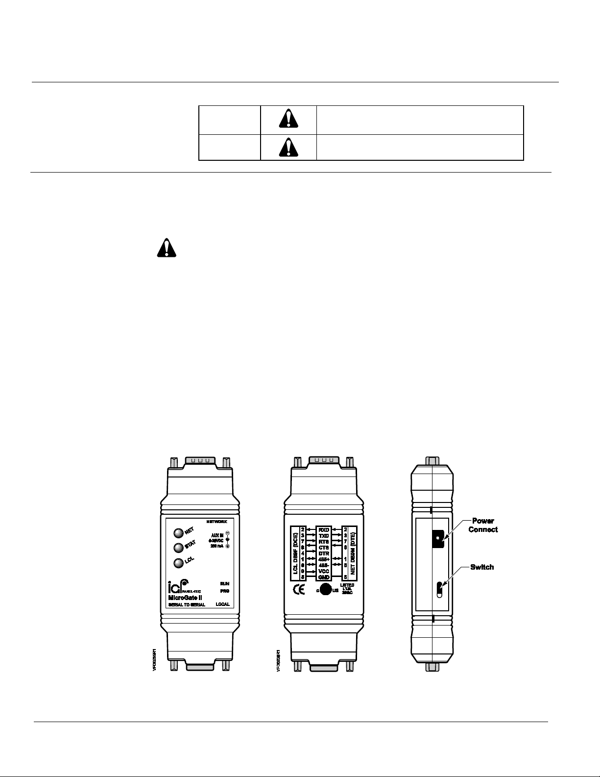
Power may be supplied by either connecting the configuration kit power supply to one side of
the unit, or by providing regulated 6 to 28 Vdc power to pin 9 of the local serial port from the
SED2. See Figure 2.
Do not connect the external 9 Vdc power supply and pin 9
of the LOCAL cable at the same time.
The Programming (PRG) Switch on the Interface Module, should always be in the RUN
position (up) for normal operations and configuration.
The PRG position is used strictly for loading firmware at the factory.
The Interface Module comes with two serial ports. See Figure 2.
The LOCAL port is for connection to a SED2 and supports both RS232 and RS485 (2-wire
and ground) communications. The LOCAL port is also used for configuration and
programming of the Interface Module.
The NETWORK port is for connection to a network and supports RS485 (2-wire)
communications.
Figure 2. Interface Module Hardware.
Page 2 Siemens Industry, Inc.
Page 3
Modbus RTU Interface Module for SED2 Technical Instructions
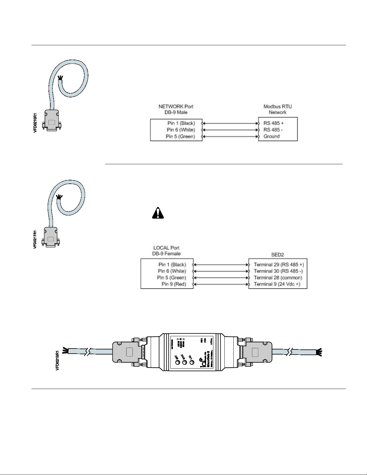
A four wire cable (Figure 5) connects the LOCAL port on the Interface Module to an
Document Number 155-767
February 25, 2009
Hardware Setup, Continued
The Interface Module is provided with two cables.
A three wire cable (Figure 3) connects the NETWORK port to a network. Because the
network connection type may vary among different installations, the cable ends are
stripped wires to provide maximum flexibility.
Figure 3. Three Wire
Network Cable.
Figure 4. RS485 Network Cable.
SED2. The cable ends in stripped wires to facilitate a connection to the SED2 drive
terminals shown below.
CAUTION:
SED2 drive power should be off while connecting
the wires to the drive terminals.
Figure 5. Four Wire
Local Port Cable.
Figure 6. SED2 Drive Cable.
Figure 7. Cables Installed on Interface Module.
Siemens Industry, Inc. Page 3
Page 4
Technical Instructions Modbus RTU Interface Module for SED2
Document Number 155-767
February 25, 2009
Hardware Setup,
Continued
LED Indicators
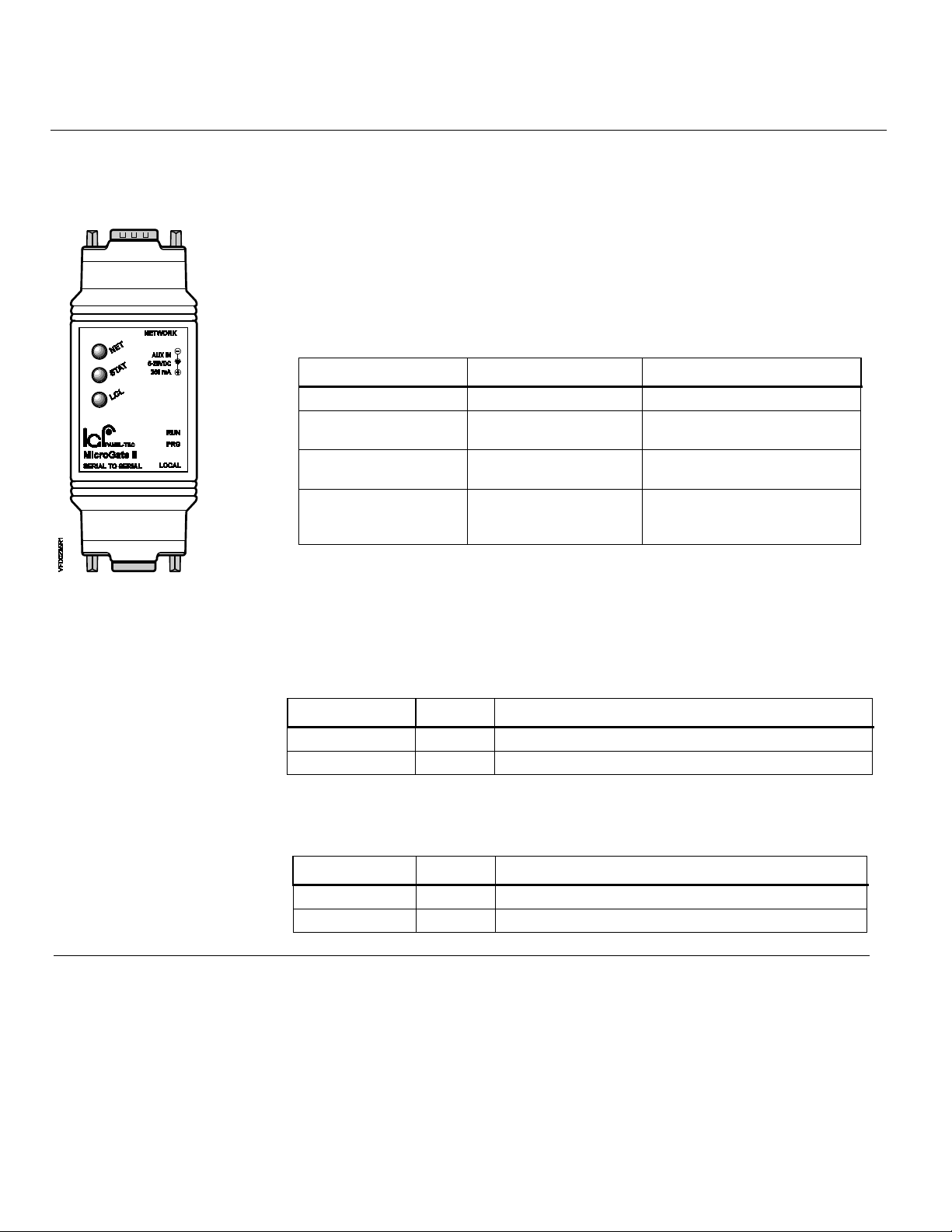
There are a total of three bi-color LED indicators on the Interface Module. See
Figure 8. The NET LED displays communications activity on the Network (Modbus)
port.
• The STAT LED displays the overall status of the Interface Module.
• The LCL LED displays communications activity on the Local (SED2) port.
During normal operations, the NET and LCL LEDs will quickly alternate red and green
flashes, making it look almost amber; this is normal.
Table 1. Interface Module General Status LED (Stat).
For this state: LED is: To indicate:
No power Off No power applied to the device.
Run Mode
Configuration Mode
Fatal Error
Flashing Green
(250 ms On, 250 ms Off)
Flashing Green
(1.5 sec on, 1.5 sec Off)
Flashing Yellow
(250 ms On, 250 ms Off)
Interface Module is operating
normally in RUN Mode.
Interface Module is in
CONFIGURATION Mode.
Interface Module has
experienced a fatal error, and
has halted communication.
Figure 8.
NOTE: If the Interface Module has been installed correctly, the STAT LED will be
flashing green, and the LCL LED will be alternating so fast between red and
green that it will appear to be glowing amber.
Table 2. Network Communication Activity LED (NET).
For this state: LED is: To indicate:
Received Data Red Data from the Modbus Network.
Transmit Data Green Data onto the Modbus Network.
Table 3. SED2 Communications Activity LED (LCL).
For this state: LED is: To indicate:
Received Data Red Data from the SED2.
Transmit Data Green Data to the SED2.
Page 4 Siemens Industry, Inc.
Page 5
Modbus RTU Interface Module for SED2 Technical Instructions
Interface Module ASCII
Interface Module RTU
Interface Module
RTU
Interface
Module ID
115200 bps
7
8
None
Odd
1
2
Document Number 155-767
February 25, 2009
Hardware Setup
Continued
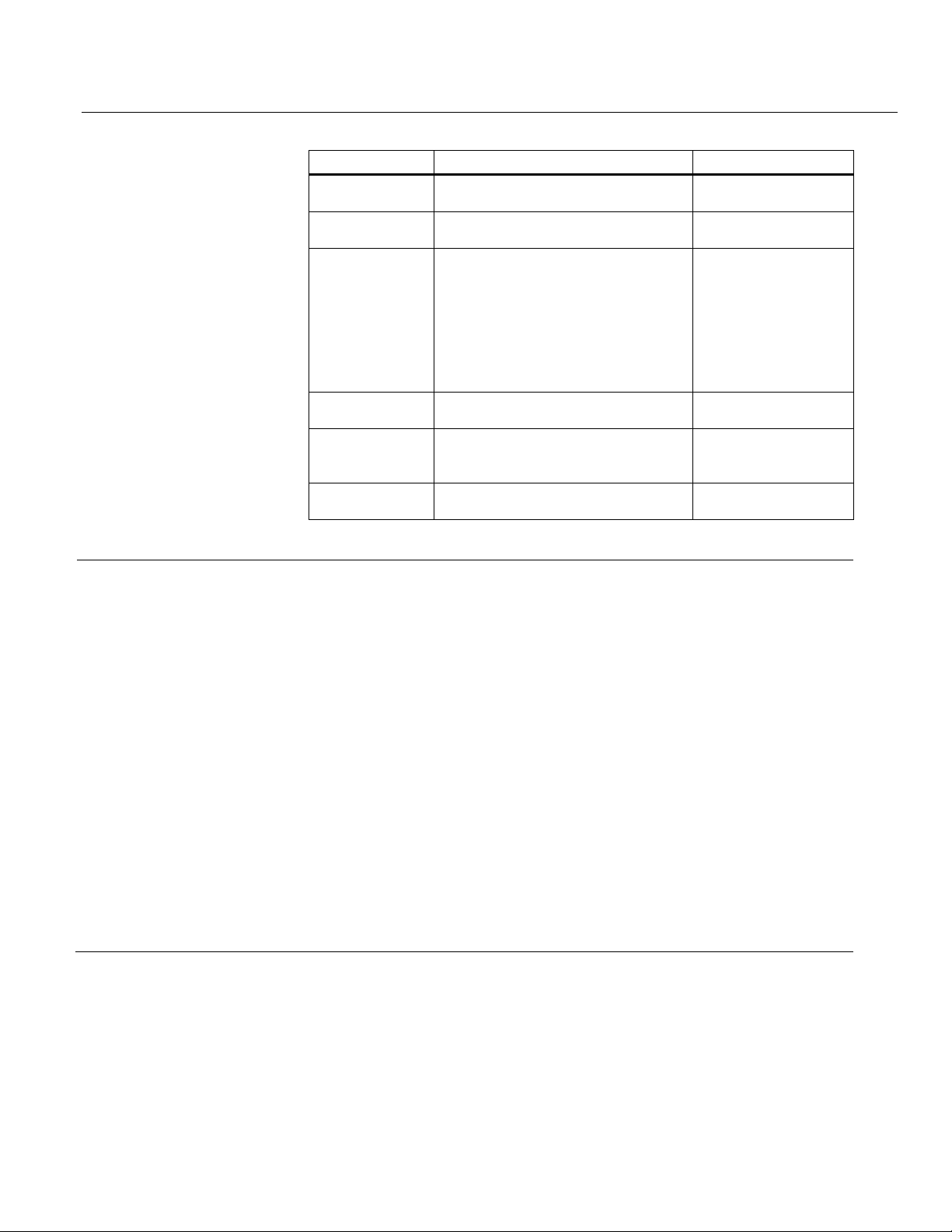
Default Configuration
Parameter Options Default
Protocol
Table 4. Configuration Options.
1… 254 2
1200 bps
4800 bps
9600 bps
Baud Rate
9600 bps
19200 bps
9600 bps
38400 bps
57600 bps
Changing the
Configuration
Data Bits
Parity
Even
Stop Bits
8
Even
1
The configuration stored in the Interface Module may be changed from the default
configuration by entering CONFIGURATION Mode.
1. Attach a configuration cable between the LOCAL port and a serial port on a
computer.
2. Start a terminal program, such as HyperTerminal, on the computer, and connect
using the following setting:
• Baud = 9600 bps
• Data bits = 8
• Parity = None
• Stop bits = 1
• Flow control = None
Siemens Industry, Inc. Page 5
3. With the Programming Switch set to RUN, apply power to the Interface Module,
and press the ENTER key within five seconds of startup. See Figure 9.
Page 6
Technical Instructions Modbus RTU Interface Module for SED2
Document Number 155-767
February 25, 2009
Changing the
Configuration,
Continued
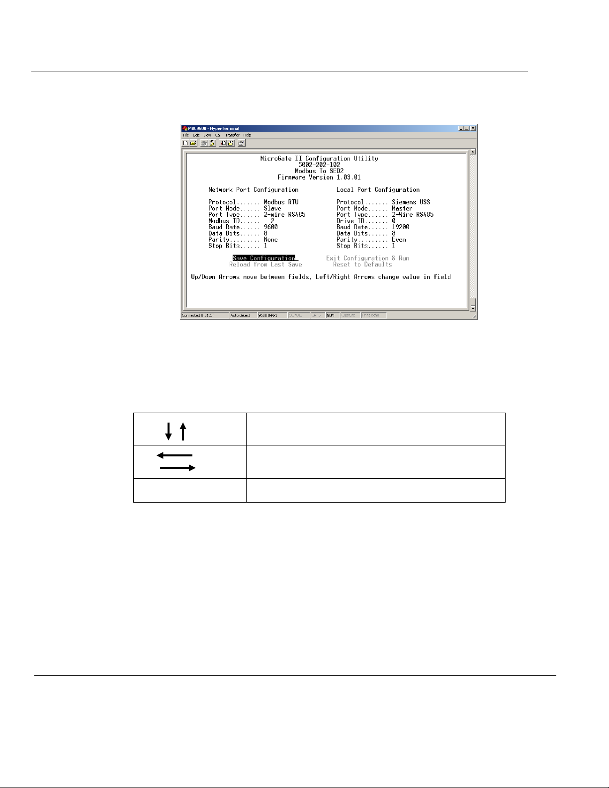
Once the Interface Module is in CONFIGURATION Mode, it will send its current
configuration to the terminal program.
Figure 9. MicroGate II Configuration Di splay.
Table 5. Keyboard Navigation.
Use the UP and DOWN arrows, on the computer
keyboard, to navigate to the field you want to change.
Change values with the LEFT and RIGHT arrows.
Save Configuration Navigate to here and press ENTER to save changes.
Page 6 Siemens Industry, Inc.
Page 7
Modbus RTU Interface Module for SED2 Technical Instructions
Document Number 155-767
February 25, 2009
SED2 Parameter
Configuration
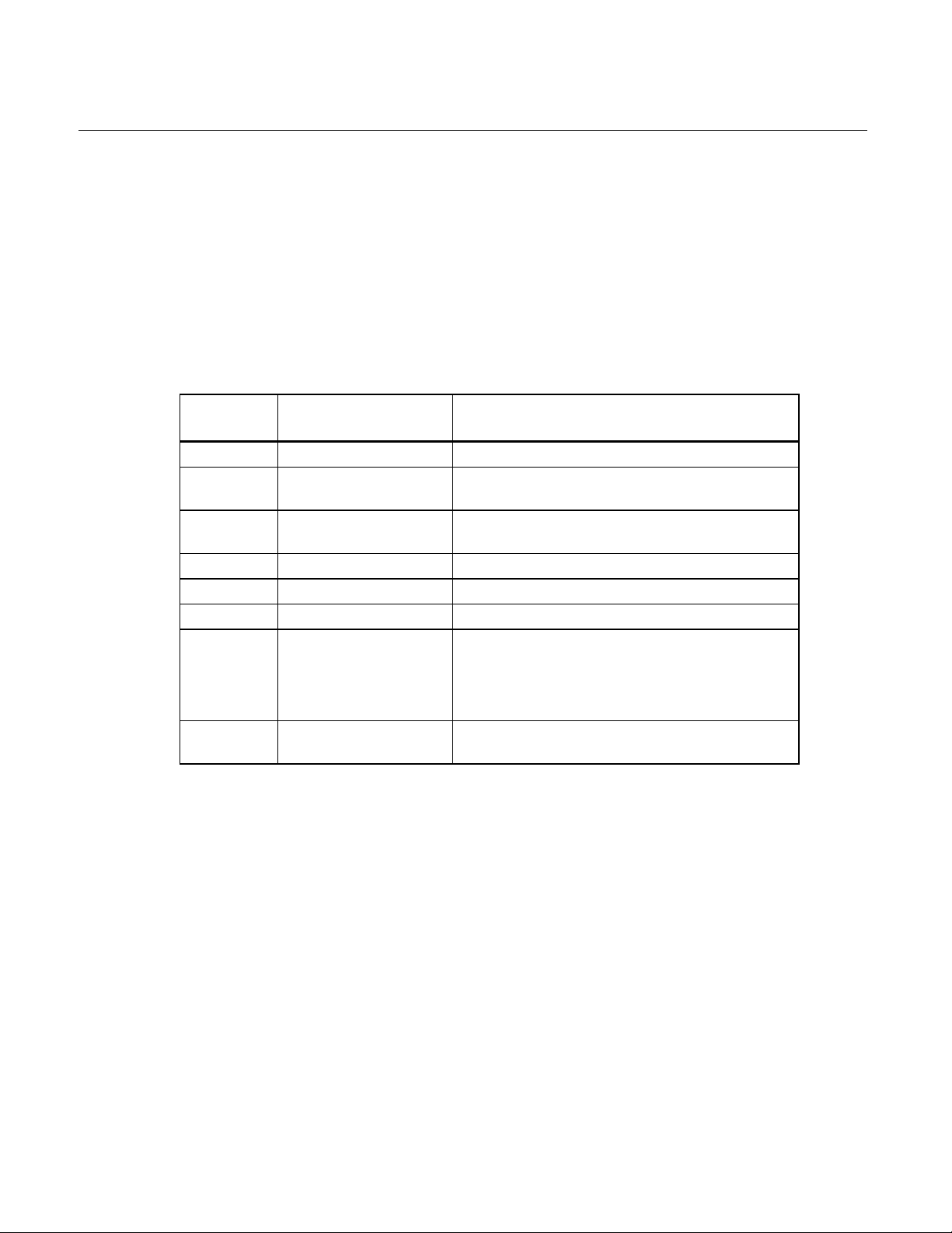
Table 6. SED2 Parameter Settings to Communicate with the MicroGate II.
The Interface Module communicates with the SED2 VFD using the USS protocol
and the following parameter configuration:
• USS address set to 0
• USS baud rate set to 19.2K
• Parity set to Even
• Number of data bits set to 8
Configure SED2 VFD parameters to communicate with the MicroGate II, per Table 3.
SED2
Parameter
P0003 User Access Level 3 (Expert Level)
P0700[0] Command Source
P1000[0] Frequency Setpoint
P2009[0] USS Normalization 0 (Disabled)
P2010[0] USS Baud Rate 7 (19.2K baud)
P2011[0] USS Address 0
P2014[0] USS telegram off time
P2041[0] Protocol Selection for
Function Setting/Value
5 if Starting/Stopping VFD from Modbus;
otherwise, DO NOT change.
5 if Setting the Frequency from Modbus;
Source
RS485 port
otherwise, DO NOT change.
0 to Disable the USS Watchdog timer.
100 or greater to enable the USS Watchdog
timer.
NOTE: Do not set to a value from 1 to 99.
0 (USS Protocol)
Siemens Industry, Inc. Page 7
Page 8

Technical Instructions Modbus RTU Interface Module for SED2
Document Number 155-767
February 25, 2009
Watchdog Timer
Setup
To enable an Interface Module Host Watchdog Function, the Interface Module Master
controls the first two holding Registers, WDOG TIME (40001) and WDOG ACTION
(40002).
When the Host Watchdog Function activates, the
Interface Module does not receive any
further communications from the Master for a period of time determined by WDOG
TIME (40001). With WDOG ACTION (40002) set to 1, the SED2 stops on loss of
communications.
To activate the
Interface Module Host Watchdog Function, set:
• WDOG TIME (40001) to the amount of time in milliseconds that must pass
with no further
Interface Module communications.
• WDOG ACTION (40002) to 1 so that the SED2 stops on loss of
communications with the Modbus master.
To deactivate the
SED2 Parameter 2014, USS Telegram Off Time, controls a Watchdog timer function for
Interface Module Host Watchdog Function, set WDOG ACTION to 0.
the USS port.
• Once the
Interface Module stops communicating with the SED2, the SED2 automatically
Interface Module establishes communications with the SED2, if the
enters the fault state with a F0070 fault number.
• Parameter P2014 specifies the timeout value for the USS Watchdog timer
function.
If P2014 is set to 0, the USS Watchdog timer is disabled. If P2014 is set to a non-zero
value, the USS Watchdog timer function is enabled and the timeout value is the P2014
non-zero value.
If using the USS Watchdog timer function with the Interface Module, set P2014 to a
value of 100 or greater so that accidental faults do not occur because of normal
communications dela ys between the Inter f ac e Modu le and the SED 2.
Page 8 Siemens Industry, Inc.
Page 9

Modbus RTU Interface Module for SED2 Technical Instructions
Document Number 155-767
February 25, 2009
Verifying the
Installation
After all necessary connections have been made, power up the SED2 and the
Interface Module. Wait approximately five seconds.
Modbus Interface
Module with
Network a s
Command Source
Modbus Interface
Module with
Network a s
Command Source
NOTE: If the Interface Module has been installed correctly, the STAT LED will
be flashing green, and the LCL LED will be alternating so fast between
red and green that it will appear to be glowing amber.
If not using the Modbus for commands, do not change P0700[0] and P1000[0].
Instead, verify communications by issuing a start command (from the source) and
checking the feedback on the Modbus master device to ensure that it reads proper
values in the appropriate Registers.
1. To verify that the Interface Module and SED2 are set up correctly, set P0700[0]
and P1000[0] to a value of 5 so that the SED2 can be controlled from the
Interface Module network.
2. From the Interface Module host, issue an Interface Module write, with of a value
of 8192 (2000h, or 50% of the maximum frequency) to the FREQ REF register
(40003 followed by a Modbus write with the value of 1 to the ENABLE register
(40004).
3. Write a value of 1 to the CMD START register to stop the drive again. The SED2
frequency can be changed at any time during this process by writing to the
FREQ REF register (40003).
Siemens Industry, Inc. Page 9
Page 10

Technical Instructions Modbus RTU Interface Module for SED2
Interface Module
Document Number 155-767
February 25, 2009
Registers
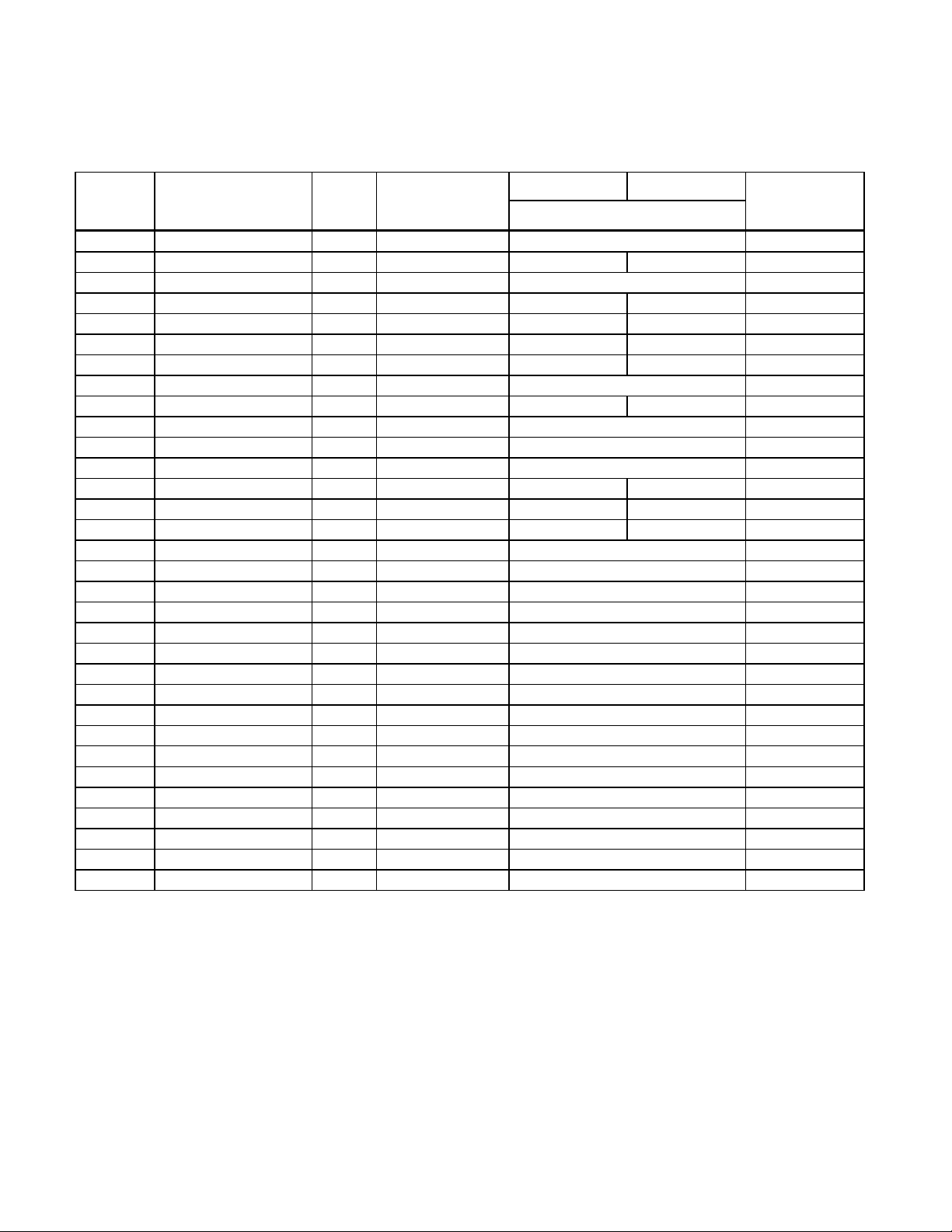
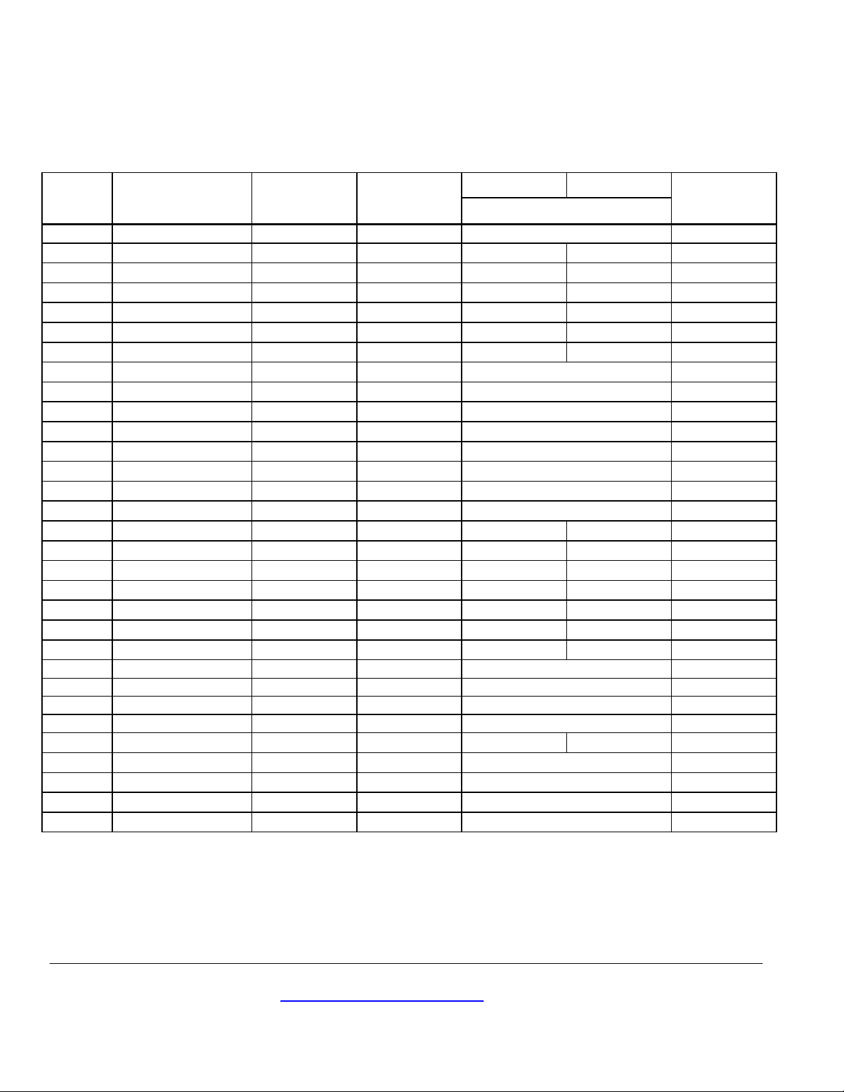
The following tables contain the lists of all Interface Module holding Registers available
on the Interface Module. The Interface Module host may write to Registers 40001
through 40023. All other Registers are read only.
There is a scaling factor included for some of the Registers. Because Modbus does not
represent floating point numbers, all floating point values in the drive are converted to
integer register values by applying a scaling (multiplication) factor. The scaling factors
are in the range of 10 to 1000.
For example: ACCEL TIME has a scaling factor of 100. If the SED2 contains a
value of 20.50, then the ACCEL TIME register will contain a value of 2050.
FREQ REF (40003) and FREQ ACTUAL (40063) are special case Registers. FREQ
REF contains the raw integer value passed in the HSW portion of a USS protocol
request to the SED2 drive. FREQ Actual contains the raw integer value passed in the
HIW portion of a USS protocol response from the SED2. Both Registers are scaled so
that a value of 4000th represents 100% of the actual frequency.
FREQ SCALED (40044) contains a scaled version of the HIW data, so that a value of
2000 in the register represents the value 4000h in the USS protocol response (and
100% of the maximum frequency).
STW and HSW refer to the 1st and 2nd control words, respectively, of PZD data
included in every poll sent from the Interface Module to the SED2 drive via the USS
protocol. ZSW and HIW refer to the 1st and 2nd status words, respectively, of PZD data
included in every poll response from the SED2 drive to the Interface Module via the USS
protocol. Registers mapped to PZD data are updated frequently.
All other parameters (except WDOG ACTION and WDOG TIME), which are handled
internally in the Interface Module, are mapped to parameters in the SED2 drive, and are
updated cyclically.
• Registers mapped to monitor parameters—
such as CURRENT or SPEED, whose values change automatically during
normal operation of the drive, without the intervention of an operator—are
updated at a rate of approximately once per second.
• Registers mapped to setup parameters—such as ACCEL TIME or FREQ
MAX, whose values typically change only via intervention by an operator—are
updated at a rate of approximately once every five seconds.
Page 10 Siemens Industry, Inc.
Page 11
Modbus RTU Interface Module for SED2 Technical Instructions
40001
WDOG TIME
MS
1
0 – 65535
––
40002
WDOG ACTION
––
1
STOP DRIVE
NO ACTION
––
40003
FREQ REF
PCT
100
0.00 – 4000h (4000h = 100%)
HSW
40005
CMD FWD REV
–– 1 REV
FWD
STW:11
40006
CMD START
–– 1 START
OFF
STW:0
40007
FAULT ACK
–– 1 ACK
NO ACK
STW:7
40009
ENABLE PID
–– 1 ENABLE
DISABLE
P2200
40010
CURRENT LMT
PCT
10
10.0 – 400.0
P0640
40011
ACCEL TIME
SEC
100
0.00 – 650.00
P1120
40013
HAND AUTO
–– 1 HAND
AUTO
P0718
40014
DIGITAL OUT 1
–– 1 ON
OFF
P0731
40015
DIGITAL OUT 2
–– 1 ON
OFF
P0732
40017
PID UP LMT
PCT
10
-200.00 – 200.00
P2291
40018
PID LO LMT
PCT
10
-200.00 – 200.00
P2292
40019
P GAIN
––
1000
0.000 – 65.000
P2280
40021
D GAIN
––
1
0 – 60
P2274
40022
FEEDBK GAIN
PCT
100
0.00 – 500.00
P2269
40023
LOW PASS
––
100
0.00 – 60.00
P2265
40025
SPEED
RPM 1 -16250 – 16250
r0022
40026
CURRENT
A
10
0 – 1638.3
r0027
40027
TORQUE
NM
10
-3250.0 – 3250.0
r0031
40029
TOTAL KWH
KWH 1 0 – 65535
r0039
40030
DC BUS VOLTS
V
1
0 – 65535
r0026
40031
REFERENCE
Hz
10
-650.0 – 650.0
r0020
Document Number 155-767
February 25, 2009
Interface Module Registers, Continued
Table 7. Interface Module Registers.
Register
Number
Description Units Scaling Factor On Text Off Text SED2
Or Range
Reference
40004 RUN ENABLE –– 1 ENABLE OFF STW:3
40008 PID SETP REF PCT 10 -200.0 – 200.0 P2240
40012 DECEL TIME SEC 100 0.00 – 650.00 P1121
40016 FREQ MAX HZ 100 1.00 – 650.00 P2000
40020 I GAIN SEC 1 0 – 60 P2285
40024 FREQ OUTPUT HZ 10 -650.0 – 650.0 r0024
40028 ACTUAL PWR KW 100 0 – 655.35 r0032
40032 RATED PWR KW 100 0 – 655.35 r0206
Page 11 Siemens Industry, Inc.
Page 12
Technical Instructions Modbus RTU Interface Module for SED2
Siemens Indus try, Inc.
+ 1 847-215-1000
Your feedback is important to us. If you have comments
Document No. 155-767
40033
OUTPUT VOLTS
V 1 0 – 65535
r0025
40034
40035
STOP RUN
––
1
STOP
RUN
ZSW:2
40036
40037
CONTROL MODE
––
1
SERIAL
LOCAL
ZSW:9
40038
ENABLED
–– 1 ON
OFF
ZSW:0
40039
40040
ANALOG IN 1
PCT
10
-300.0 – 300.0
r0754/0
40041
40042
ANALOG OUT 1
PCT
10
-100.0 – 100.0
r0774/0
40043
ANALOG OUT 2
PCT
10
-100.0 – 100.0
r0774/1
40044
40045
PID SETP OUT
PCT
10
-100.0 – 100.0
r2250
40046
40047
PI FEEDBACK
PCT
10
-100.0 – 100.0
r2266
40048
DIGITAL IN 1
–– 1 ON
OFF
r0722:0
40049
40050
DIGITAL IN 3
–– 1 ON
OFF
r0722:2
40051
40052
DIGITAL IN 5
–– 1 ON
OFF
r0722:4
40053
DIGITAL IN 6
–– 1 ON
OFF
r0722:5
40054
40055
LAST FAULT
–– 1 0 – 65535
r0947
40056
1ST FAULT
–– 1 0 – 65535
r0947
40058
3RD FAULT
–– 1 0 – 65535
r0947
40059
WARNING
––
1
WARN
OK
ZSW:7
40060
LAST WARNING
–– 1 0 – 65535
r2110
40062
DRIVE MODEL
–– 1 0 – 655.35
r0200
40063
Document Number 155-767
February 25, 2009
Interface Module Registers, Continued
Table 8. Interface Module Registers.
Register
Number
Description Units Scaling
Factor
FWD REV –– 1 FWD REV ZSW:14
AT MAX FREQ –– 1 MAX NO ZSW:10
READU TO RUN –– 1 READY OFF ZSW:1
ANALOG IN 2 PCT 10 -300.0 – 300.0 r0754/1
FREQ ACTUAL PCT 10 00.0 – 100.0 HIW
PID OUTPUT PCT 10 -100.0 – 100.0 r2294
DIGITAL IN 2 –– 1 ON OFF r0722:1
On Text Off Text SED2
Or Range
Reference
DIGITAL IN 4 –– 1 ON OFF r0722:3
FAULT –– 1 FAULT OK ZSW:3
40057 2ND FAULT –– 1 0 – 65535 r0947
40061
INVERTER VER –– 100 0.00 – 655.35 r0018
FREQ ACTUAL –– 1 0 – 4000h (4000H = 100%) HIW
Information in this publication is based on current specifications. The company reserves the right to make changes in specifications and models as
design improvements are introduced. Product or company names mentioned herein may be the trademarks of their respective owners.
© 2009 Siemens Industry, Inc.
Building Technologies Division
1000 Deerfield Parkway
Buffalo Grove, IL 60089
about this document, please send them to
Printed in the USA
Page 12
 Loading...